JP4295919B2 - Method for improving penetration of catheter tip and stent - Google Patents
Method for improving penetration of catheter tip and stent Download PDFInfo
- Publication number
- JP4295919B2 JP4295919B2 JP2000534263A JP2000534263A JP4295919B2 JP 4295919 B2 JP4295919 B2 JP 4295919B2 JP 2000534263 A JP2000534263 A JP 2000534263A JP 2000534263 A JP2000534263 A JP 2000534263A JP 4295919 B2 JP4295919 B2 JP 4295919B2
- Authority
- JP
- Japan
- Prior art keywords
- distal
- distal end
- tip
- balloon
- catheter
- Prior art date
- Legal status (The legal status is an assumption and is not a legal conclusion. Google has not performed a legal analysis and makes no representation as to the accuracy of the status listed.)
- Expired - Fee Related
Links
- 238000000034 method Methods 0.000 title description 7
- 230000035515 penetration Effects 0.000 title 1
- 238000003780 insertion Methods 0.000 claims description 20
- 230000037431 insertion Effects 0.000 claims description 20
- 210000004204 blood vessel Anatomy 0.000 claims description 17
- 238000005520 cutting process Methods 0.000 claims description 2
- 238000002560 therapeutic procedure Methods 0.000 claims description 2
- 210000001124 body fluid Anatomy 0.000 abstract description 3
- 239000010839 body fluid Substances 0.000 abstract description 3
- 239000012530 fluid Substances 0.000 description 32
- 230000003902 lesion Effects 0.000 description 15
- 239000000463 material Substances 0.000 description 11
- 239000000853 adhesive Substances 0.000 description 8
- 230000001070 adhesive effect Effects 0.000 description 8
- 238000011282 treatment Methods 0.000 description 7
- 208000031481 Pathologic Constriction Diseases 0.000 description 6
- 238000004891 communication Methods 0.000 description 6
- 230000036262 stenosis Effects 0.000 description 6
- 208000037804 stenosis Diseases 0.000 description 6
- 229910001000 nickel titanium Inorganic materials 0.000 description 5
- HLXZNVUGXRDIFK-UHFFFAOYSA-N nickel titanium Chemical compound [Ti].[Ti].[Ti].[Ti].[Ti].[Ti].[Ti].[Ti].[Ti].[Ti].[Ti].[Ni].[Ni].[Ni].[Ni].[Ni].[Ni].[Ni].[Ni].[Ni].[Ni].[Ni].[Ni].[Ni].[Ni] HLXZNVUGXRDIFK-UHFFFAOYSA-N 0.000 description 5
- 230000035699 permeability Effects 0.000 description 5
- 239000004696 Poly ether ether ketone Substances 0.000 description 4
- 230000008859 change Effects 0.000 description 4
- 230000007423 decrease Effects 0.000 description 4
- 229920002530 polyetherether ketone Polymers 0.000 description 4
- JOYRKODLDBILNP-UHFFFAOYSA-N Ethyl urethane Chemical compound CCOC(N)=O JOYRKODLDBILNP-UHFFFAOYSA-N 0.000 description 3
- 239000004698 Polyethylene Substances 0.000 description 3
- 238000002399 angioplasty Methods 0.000 description 3
- 230000008901 benefit Effects 0.000 description 3
- 230000006870 function Effects 0.000 description 3
- 229920001903 high density polyethylene Polymers 0.000 description 3
- 239000004700 high-density polyethylene Substances 0.000 description 3
- -1 polyethylene Polymers 0.000 description 3
- 229920000573 polyethylene Polymers 0.000 description 3
- 238000000926 separation method Methods 0.000 description 3
- 239000012781 shape memory material Substances 0.000 description 3
- 230000007704 transition Effects 0.000 description 3
- 229920000339 Marlex Polymers 0.000 description 2
- 239000004952 Polyamide Substances 0.000 description 2
- 229920002614 Polyether block amide Polymers 0.000 description 2
- 230000001154 acute effect Effects 0.000 description 2
- 210000001367 artery Anatomy 0.000 description 2
- 230000036760 body temperature Effects 0.000 description 2
- 201000010099 disease Diseases 0.000 description 2
- 208000037265 diseases, disorders, signs and symptoms Diseases 0.000 description 2
- 239000003550 marker Substances 0.000 description 2
- 239000012528 membrane Substances 0.000 description 2
- 229920002647 polyamide Polymers 0.000 description 2
- 229920002635 polyurethane Polymers 0.000 description 2
- 239000004814 polyurethane Substances 0.000 description 2
- 238000012360 testing method Methods 0.000 description 2
- 238000003466 welding Methods 0.000 description 2
- 229920006055 Durethan® Polymers 0.000 description 1
- 238000012276 Endovascular treatment Methods 0.000 description 1
- 229910000990 Ni alloy Inorganic materials 0.000 description 1
- 239000004677 Nylon Substances 0.000 description 1
- 239000004830 Super Glue Substances 0.000 description 1
- 229910001069 Ti alloy Inorganic materials 0.000 description 1
- RTAQQCXQSZGOHL-UHFFFAOYSA-N Titanium Chemical compound [Ti] RTAQQCXQSZGOHL-UHFFFAOYSA-N 0.000 description 1
- 210000003484 anatomy Anatomy 0.000 description 1
- 238000005452 bending Methods 0.000 description 1
- 239000011248 coating agent Substances 0.000 description 1
- 238000000576 coating method Methods 0.000 description 1
- 238000010276 construction Methods 0.000 description 1
- 238000007887 coronary angioplasty Methods 0.000 description 1
- 238000012631 diagnostic technique Methods 0.000 description 1
- 238000010586 diagram Methods 0.000 description 1
- FGBJXOREULPLGL-UHFFFAOYSA-N ethyl cyanoacrylate Chemical compound CCOC(=O)C(=C)C#N FGBJXOREULPLGL-UHFFFAOYSA-N 0.000 description 1
- 238000002594 fluoroscopy Methods 0.000 description 1
- 239000003978 infusion fluid Substances 0.000 description 1
- 230000003993 interaction Effects 0.000 description 1
- 238000004519 manufacturing process Methods 0.000 description 1
- 239000002184 metal Substances 0.000 description 1
- 229910052751 metal Inorganic materials 0.000 description 1
- 239000007769 metal material Substances 0.000 description 1
- 229920001778 nylon Polymers 0.000 description 1
- 229920000642 polymer Polymers 0.000 description 1
- 230000004044 response Effects 0.000 description 1
- 229910001285 shape-memory alloy Inorganic materials 0.000 description 1
- 229920000431 shape-memory polymer Polymers 0.000 description 1
- 230000007480 spreading Effects 0.000 description 1
- 238000003892 spreading Methods 0.000 description 1
- 239000010935 stainless steel Substances 0.000 description 1
- 229910001220 stainless steel Inorganic materials 0.000 description 1
- 239000000758 substrate Substances 0.000 description 1
- 230000001225 therapeutic effect Effects 0.000 description 1
- 239000010936 titanium Substances 0.000 description 1
- 238000012285 ultrasound imaging Methods 0.000 description 1
- 230000002792 vascular Effects 0.000 description 1
- 210000005166 vasculature Anatomy 0.000 description 1
Images


Classifications
-
- A—HUMAN NECESSITIES
- A61—MEDICAL OR VETERINARY SCIENCE; HYGIENE
- A61M—DEVICES FOR INTRODUCING MEDIA INTO, OR ONTO, THE BODY; DEVICES FOR TRANSDUCING BODY MEDIA OR FOR TAKING MEDIA FROM THE BODY; DEVICES FOR PRODUCING OR ENDING SLEEP OR STUPOR
- A61M25/00—Catheters; Hollow probes
- A61M25/0067—Catheters; Hollow probes characterised by the distal end, e.g. tips
- A61M25/0068—Static characteristics of the catheter tip, e.g. shape, atraumatic tip, curved tip or tip structure
-
- A—HUMAN NECESSITIES
- A61—MEDICAL OR VETERINARY SCIENCE; HYGIENE
- A61M—DEVICES FOR INTRODUCING MEDIA INTO, OR ONTO, THE BODY; DEVICES FOR TRANSDUCING BODY MEDIA OR FOR TAKING MEDIA FROM THE BODY; DEVICES FOR PRODUCING OR ENDING SLEEP OR STUPOR
- A61M25/00—Catheters; Hollow probes
- A61M25/0067—Catheters; Hollow probes characterised by the distal end, e.g. tips
- A61M25/0074—Dynamic characteristics of the catheter tip, e.g. openable, closable, expandable or deformable
-
- A—HUMAN NECESSITIES
- A61—MEDICAL OR VETERINARY SCIENCE; HYGIENE
- A61M—DEVICES FOR INTRODUCING MEDIA INTO, OR ONTO, THE BODY; DEVICES FOR TRANSDUCING BODY MEDIA OR FOR TAKING MEDIA FROM THE BODY; DEVICES FOR PRODUCING OR ENDING SLEEP OR STUPOR
- A61M25/00—Catheters; Hollow probes
- A61M25/0067—Catheters; Hollow probes characterised by the distal end, e.g. tips
- A61M25/008—Strength or flexibility characteristics of the catheter tip
- A61M2025/0081—Soft tip
-
- A—HUMAN NECESSITIES
- A61—MEDICAL OR VETERINARY SCIENCE; HYGIENE
- A61M—DEVICES FOR INTRODUCING MEDIA INTO, OR ONTO, THE BODY; DEVICES FOR TRANSDUCING BODY MEDIA OR FOR TAKING MEDIA FROM THE BODY; DEVICES FOR PRODUCING OR ENDING SLEEP OR STUPOR
- A61M25/00—Catheters; Hollow probes
- A61M25/10—Balloon catheters
- A61M2025/1043—Balloon catheters with special features or adapted for special applications
- A61M2025/1093—Balloon catheters with special features or adapted for special applications having particular tip characteristics
-
- A—HUMAN NECESSITIES
- A61—MEDICAL OR VETERINARY SCIENCE; HYGIENE
- A61M—DEVICES FOR INTRODUCING MEDIA INTO, OR ONTO, THE BODY; DEVICES FOR TRANSDUCING BODY MEDIA OR FOR TAKING MEDIA FROM THE BODY; DEVICES FOR PRODUCING OR ENDING SLEEP OR STUPOR
- A61M25/00—Catheters; Hollow probes
- A61M25/01—Introducing, guiding, advancing, emplacing or holding catheters
- A61M25/02—Holding devices, e.g. on the body
- A61M25/04—Holding devices, e.g. on the body in the body, e.g. expansible
-
- A—HUMAN NECESSITIES
- A61—MEDICAL OR VETERINARY SCIENCE; HYGIENE
- A61M—DEVICES FOR INTRODUCING MEDIA INTO, OR ONTO, THE BODY; DEVICES FOR TRANSDUCING BODY MEDIA OR FOR TAKING MEDIA FROM THE BODY; DEVICES FOR PRODUCING OR ENDING SLEEP OR STUPOR
- A61M25/00—Catheters; Hollow probes
- A61M25/10—Balloon catheters
Abstract
Description
【0001】
(発明の分野)
本発明はガイド要素と組み合わせて使用される医療用器具に一般的に関する。より詳細には、本発明は改良された先端部とガイドワイア管腔とを有する血管内カテーテルに関する。本発明は病変部にわたって、またはステントを通じて最適に配置するために最末端に位置する先端部の形状を変化させるための手段を有する。本発明は更に内側ガイドワイア管内に配置される最も内側のガイドワイア管を有する。
【0002】
(発明の背景)
血管内の疾患は一般に経皮的経管的血管形成術(PTA)及び経皮的経管的冠動脈形成術(PTCA)などの比較的低侵襲性のカテーテルに基づいた技術によって治療される。カテーテルに基づいた治療及び診断技術としては、アテレクトミー、レーザ照射、超音波画像法なども含まれる。これらの治療法は当該技術分野においてはよく知られたものであり、通常は、バルーンカテーテルや他の治療要素がカテーテルの末端の近傍に配されたカテーテルを、ガイドワイアとともに、場合に応じて他の血管内要素と組み合わせて使用する。一般的なバルーンカテーテルは、末端近傍にバルーンが取り付けられ、基端にマニホルドが取り付けられた長尺のシャフトを有する。使用に際しては、バルーンカテーテルをガイドワイア上に進め、バルーンを病変血管の狭窄部に接するように配置する。次にバルーンを膨らませ、血管の狭窄を広げる。血管内疾患を治療するためのより最近の技術では、バルーン拡張カテーテルを使用して血管の管腔内の狭窄部にまでステントを搬送して留置する。このステントは全体を通じて管腔が延びるほぼ円筒状の形状を一般になす。ステントは病変部位に配置されると、バルーンによって萎んだ状態から膨らんだ状態へと拡張させられることにより、ステントの全長にわたって血管の管腔が閉鎖することを物理的に防止する。ステントの壁は、好ましくは金属材料にて形成され、空間が間に介在する互いに連結された複数のストラットを一定の規則性にて有する。これらの空間は円筒状の壁を通じて開口する。こうした構成のステントは、米国特許第5,449,373号及び国際特許出願公開公報第WO96/03092号に開示されており、ここにその開示の全体を援用するものである。こうしたステントを送達するために特に構成されたカテーテルは米国特許第4,950,227号に開示されているが、その開示もここに援用するものである。
【0003】
ガイドワイアと組み合わせて使用されるバルーンカテーテルには基本的に2つの種類がある。すなわち、ワイア導入型(Over−the−wire)(OTR)カテーテル、及び単独操作者交換型(Single−operator−exchange)(SOE)カテーテルである。OTWカテーテル及びSOEカテーテルの構成及び使用はいずれも当該技術分野ではよく知られたものである。OTWカテーテルの一例が、アーニー(Arney)等に付与され、この出願とともに譲渡された米国特許第5,047,045号に示されているが、ここにその開示を援用するものである。SOEバルーンカテーテルの一例が、キース(Keith)に付与され、この出願とともに譲渡された米国特許第5,156,594号に開示されており、ここにその開示を援用するものである。
【0004】
PTA及びPTCAカテーテルは、可推性(pushability)、可辿性(trackability)、及び、可通性(crossability)が最適化されるように好ましくは構成される。可推性は、カテーテルの基端からカテーテルの末端に力を伝達する能力として定義される。可辿性は、曲折した脈管内を進む能力として定義される。可通性は、バルーンカテーテルを脈管内の狭窄部に通過させる能力として定義される。
【0005】
特定のカテーテルの構成の可辿性は、カテーテルの末端部分の可辿性において分析される。これは、この部分は、処置すべき狭窄部位に到達するために小さな曲がりくねった血管を通じてガイドワイアを辿らなければならないためである。より柔軟な末端部分により可辿性が向上することが示されている。更に、カテーテルシャフトの、剛性の高い基端側部分からより柔軟な末端側部分への移行において、可撓性の異なるこれら2つのシャフト部分の間の接合部では容易に捩れが生じることが示されている。また、末端側部分の可撓性を大きくすることによってカテーテルのこの部分はカテーテルの基端から押されにくくなる。
【0006】
可通性は、カテーテルの末端側部分の可撓性によって影響される点において特定のカテーテルの構成の可辿性に関連するが、更に、狭隘な病変部の領域ではカテーテルの可通性はカテーテルの末端側の先端部の構成に影響される。末端側先端部は、ガイドワイアを辿るバルーンの末端側の領域、及び、最も末端側の部分において、最初に狭窄部を通過させられる部分を備える。すなわち、ここにその開示を援用するところの、発明の名称が「可辿性の向上したワイア導入カテーテル」(“OVER−THE−WIRE CATHETER WITH IMPROVED TRACKABILITY”)である、1997年10月15日出願の同時係属中の米国特許出願第08/950,864号に開示されるもののような、可通性の向上した先端部を提供することに多大な労力が費やされてきた。
【0007】
上述したような先端部の構成では可辿性及び可通性は向上しているものの、こうした先端部の構成はステントを配置及び拡張するうえで行われる術式には適当ではないことが示された。より詳細には、ステントの最初の配置において、萎んだ状態のバルーン上にステントが予め装着され、改良された先端部の構成により、この先端部が病変を通過する先導端を与えるために、病変部にわたってステントを配置することが容易となる。しかし、この時点で、バルーンを膨らませてその後に萎ませることによりステントを拡張することが一般的な方法である。次いでバルーンカテーテルはガイドワイア上を所定の距離だけ引き戻され、ステントの配置をX線透視法により評価する。ステントを血管壁に対して適当に係止させるためにバルーンを再びステントを通じて末端側に動かし、ステント内にて後にバルーンを膨らませる必要がしばしばある。こうした場合、バルーンカテーテルをガイドワイア上で末端側に動かしてステントにわたってバルーンを配置しなければならない。こうした状況では、先端部を最初にステントの内側に通過させなければならない。病変部を通じたバルーンカテーテルの可通性を向上させる構成を有する先端部は、ステントを通過する際にステントのストラットに引っ掛かってしまい、ステントを後に拡張させることが困難となる場合がある。このことは、先端部の先導端が湾曲部の外側壁に引っ掛かる曲折部において特に著明であるが、これは、ガイドワイアは湾曲部の外径に対して押圧される傾向があり、カテーテルの最末端の先端部は湾曲をなぞる際に同じ方向に付勢されるためである。
【0008】
病変部への可通性において最適化されているがステントに挿通させるうえで難点を有する先端部の構成に関連する上記の問題点は、同じ動脈内のステントの末端側に位置する病変を後に処置する際にも問題となる。より末端側の病変を拡張するためには、使用するバルーン拡張カテーテルは、これに先立って動脈内にステントが留置されている場合、まずステントの管腔を通過させられなけらばならない。したがって先端部がストラットに引っ掛かる同様な問題が生ずる。
【0009】
したがって、病変を通過するように構成されるとともに、ストラットに引っ掛かることなくステントの内腔を通過させるうえで好適な第2の形態に変換すなわち変化させることが可能な先端部を有するカテーテルの構成が求められているがこれまでのところこの要求は満たされていなかった。本発明は、こうした先端部の構成、すなわち、カテーテルの最末端部分の形態を変化させるための手段を有するガイドワイアと組み合わされる先端部の構成を提供することにより、ステントの管腔を通過するうえで問題となるストラットと先端部との相互作用を防止するものである。
【0010】
(発明の概要)
本発明は、血管の管腔内の所定の位置において血管の血管内治療を行うために末端の近傍に治療要素が配されたカテーテルアセンブリに関するものである。好ましい実施形態には、明細書において詳細に説明されるワイア導入型バルーンカテーテルが含まれるが、バルーン拡張型カテーテルには、固定ワイア型カテーテルや単独操作者交換型カテーテルなどの任意の公知のバルーンカテーテルが含まれる。更に、本明細書において開示されるカテーテルの末端の近傍に配される治療要素はバルーンであるが、他の任意の公知の治療要素をカテーテルに取り付けてここに開示される発明を実施することが可能である。
【0011】
ワイア導入型カテーテルは、一般的に、基端と末端とを有し、内部を通じてガイドワイア受容管腔が延びる長尺の管状要素を有する。この長尺の管状要素は、やはり内側管状要素の全長の一部を覆って延びる外側管状要素内に同軸に配される。内側管状要素は外側管状要素を越えて末端方向に延び、これら2個の管状要素の間には環状空間によって膨張管腔が形成される。カテーテルの末端近傍には、基端と末端とを有するバルーンが取り付けられ、その内部に、膨張管腔と流体移動可能に連通する所定の内部容積を形成する。好ましい実施形態においては、バルーンはその基端において、外側管状要素の末端近傍に密封可能に取り付けられ、外側管状要素を越えて延びる内側管状要素の外側に密封可能に連結された末端へと末端方向に延びる。カテーテルの基端は、内側の長尺管状要素の管腔内に延びるガイドワイア受容ポートと環状の膨張管腔に流体移動可能に連通する膨張ポートとを与えるハブアセンブリを有する。
【0012】
カテーテルは先端部を有するが、この先端部は、好ましい実施形態においては、バルーンの末端側にあたるカテーテルの部分であり、内部を通じて延びるガイドワイア管腔を有する内側管状要素の一部によって一般に形成されている。この先端部は、最初にカテーテルがガイドワイアを辿ることを助け、更に拡張されるべき病変部に通過させることを助けるうえで最適であるように構成されている。すなわち、先端部の可撓性及び形状は、挿通を容易とするために改変される。例として、先端部は内側管状要素の基端側の径と比較して小径となるようにネック状に形成するか、あるいは、閉塞した血管に容易に挿通されるように、末端方向に向けて小径化した外径を有する円錐状の形状に形成することが可能である。
【0013】
本発明の一実施形態は、血管腔の閉塞部及び留置されたステントの両方に挿通するためのカテーテル先端部アセンブリであって、(a)基端と末端とを有するとともに内部を通じてガイドワイア受容管腔が延びる長尺の内側管状要素と、(b)前記内側管状要素の末端近傍において治療処置を行うためのバルーンであって、前記内側管状要素の末端部は前記バルーンを越えて末端方向に延びてカテーテル先端部を形成し、該カテーテル先端部は、内部を通じて延びるガイドワイアを辿るための先導端を与えることと、(c)前記血管腔の閉塞部に挿通するための第1の形態から、留置されたステントに挿通するための第2の形態へと前記カテーテル先端部の形態を変化させるための手段であって、該手段は、前記カテーテル先端部に形成されたミシン目において離断可能な最末端の先端部を含み、前記カテーテル先端部は、前記最末端の先端部が離断されることにより第2の形態に変化し、前記第2の形態におけるカテーテル先端部の末端は、第1の形態におけるカテーテル先端部の末端よりも大きな断面積を有することとを備えるカテーテル先端部アセンブリを提供する。
本発明の異なる実施形態は、第1の形態にある場合に、病変部に通過させるうえで最適であるような先端部の構成ならびに先端部及びガイドワイアの構成を提供するものである。先端部または先端部とガイドワイアとの組み合わせは、第2の形態にある場合に、先端部が、特に血管の屈曲部に留置されたステント内のストラットに引っ掛からないために、留置されたステントに通過させるうえで最適である。
【0014】
第1の一連の実施形態では、先端部アセンブリは、血管腔内の閉塞部に挿通するための第1の形態から、留置されたステントに挿通するための第2の形態にカテーテルの形態を変化させるための手段を有する。一実施形態では、閉塞部を処置した後に外される離断可能な末端側先端部を有し、ステントに通過させるのにより適した先端部の基端側の部分が残される。先端部の残りの部分は断面においてより球根状の形状をなすか、より大径のガイドワイアとともに使用されるより大径の管腔を有する。
【0015】
別の一実施形態においては、最末端の先端部は、最末端部が内側管状要素上に折り返されることによりその形態が変化し、第1の形態においては、先端部は病変すなわち閉塞部に通過させられ、第2の形態においては、折り返された部分がストラットに容易には引っ掛からないより球根状の形状をなす先端部を形成する。または、先端部は直線状の形態から屈曲した状態のステントへの挿通を容易とする屈曲形態へと変化可能に構成することが可能である。
【0016】
別の一実施形態においては、内側管状要素をカテーテル内部で摺動可能に構成するか、あるいは、延ばされた状態では病変部に容易に挿通可能な先端部を与えるが、引き込まれた場合には、残りの先端部が、ステントのストラットに引っ掛かる確率が低くなるようにより球根状の形状、すなわち丸みを帯びた形状をなすようなシースを利用することが可能である。
【0017】
最後に、カテーテルの先端部は、内側管状要素に回転可能に取り付けられる、バルーンの末端側に延びる最末端部を有するように構成することが可能である。回転可能に取り付けられた先端部の内腔には、先端部の管腔において少なくとも1つの螺旋状突起を形成することが可能である。カテーテルがこれに挿通されたガイドワイアに対して動かされる場合、螺旋状突起とガイドワイアとの摩擦によって先端部が回転し、先端部がステントのストラットに引っ掛かる確率が低減する。
【0018】
第2の一連の実施形態では、カテーテルの先端部アセンブリとともに用いられるガイドワイアの形態は、ガイドワイアが先端部に対して選択的に配置されている場合にカテーテルの末端側先端部がステントのストラットに引っ掛かることを防止するような形状に形成されており、このガイドワイアの形態によって、先端部はストラットから逸らされる、すなわち引き離される一方で、ガイドワイアはステントと接触した状態に保たれる。この構成では、選択された位置において予め形成された屈曲部を有するか、もしくは、カテーテルがステントに挿通される際にステントの内腔内に配置される1以上の螺旋状コイルを有するガイドワイアを形成することが含まれる。または、ガイドワイアは、引き込まれた位置において、末端側先端部でより球根状の断面を与えることによりカテーテルの先端部がステントのストラットに引っ掛かることを防止するような球根状部分を有することも可能である。
【0019】
別の一実施形態においては、ガイドワイアをカテーテルの基端から振動させることにより、バルーンの末端側にあたるガイドワイアの部分が予め選択されたパターンにて振動し、これによりステントのストラットに引っ掛かる可能性のあるカテーテルの先端部を逸らせることが可能である。
【0020】
カテーテルの末端側先端部は、先端部の末端を包囲する膨張可能な袖部を有するように構成することが可能である。この袖部は先端部の壁に設けられた孔を介してガイドワイア管腔と流体移動可能に連通することが可能である。ガイドワイア管腔に流体を注入し、先端部にわたってガイドワイアに沿った充分な圧力落差が生じることにより、膨張流体の一部が袖部を満たし、ステントの管腔に通過させられる際にステントのストラットにより引っ掛かりにくい、より球根状の形状をなす全体的な先端部の形状を与える。
【0021】
本発明には、第1のバルーン、及び、第1のバルーンの末端側に配される第2の末端側の膨張可能なバルーンすなわち袖部を有するバルーンカテーテルが含まれる。この第2の末端側のバルーンを膨張させて最末端領域の断面形状すなわち径方向の最大の大きさを大きくすることが可能である。最末端領域の断面形状を大きくすることにより、最末端をステントの内壁または端部から逸らせることが可能である。一実施形態においては、第1のバルーンの内部は末端側のバルーンの内部と流体移動可能に連通している。これらの実施形態は、この構成によらなければカテーテルの全長にわたって延びる管すなわち管腔を必要とする、末端側のバルーンのための別個の膨張管腔を必要としないという利点を有する。
【0022】
一実施形態においては第1のバルーンと末端側のバルーンとの間に逆止弁を配して、末端側バルーンが急速に萎むことを防止することが可能である。この実施形態では、第1のバルーンを膨張させることにより、第2のバルーンも膨らまされ、第1のバルーンを萎ませる際に末端側バルーンを膨張した状態に保つことが可能である。別の一実施形態においては、第1のバルーンと末端側バルーンとの間の流体空間に制御可能な弁を配する。この制御可能な弁を開放することにより、流体は第1のバルーンから末端側のバルーンに流れることが可能である。末端側バルーンと第1のバルーンとの間の流体の流れはこの弁を操作することにより遮断することが可能である。こうした弁として第1の開放位置と第2の閉鎖位置との間で切換え可能なものがある。別の弁として、閉鎖位置に維持されるように付勢され、プルワイアによって、プルワイアが引き込まれている場合に開放位置に保たれるように操作することが可能なものがある。この実施形態においては、プルワイアを放すことによって弁は閉鎖状態に復帰する。
【0023】
本発明を採用したバルーンカテーテルとして、壁と内部を通じて延びる管腔とを有する管を備えた末端領域を有するものがある。この管は体内への挿入後に第2の形態をとるように予め緊張が与えられている。好ましい末端領域の1つは、ニチノールや形状記憶合金などの形状記憶材料にて形成され、体温に達すると末端領域の径方向の最大の大きさにまで拡大する。こうしたカテーテルとして、長手方向のスリット内に複数のフラップを有する末端領域を備えたものがあり、これらのフラップは暖かい体液によって温度が上昇した場合に外側にカールする。こうしたカテーテルとして、末端の手前において終端する複数のスリットが設けられた最末端を有するものがある。この実施形態においては、この最末端を術者が切り離すことにより、長手方向のスリットが露出して、先端部は暖かい体液に接触すると拡大する。
【0024】
本発明に基づくカテーテルの1つは、内側管及び該内側管の内部に摺動可能に配された最も内側の管を有する末端領域を備える。この最も内側の管は最末端において内側管に固定することが可能である。この実施形態においては、末端領域は、間にフラップが形成される複数の長手方向スリットを有する。最も内側の管は、基端側に引き込むことが可能であり、これにより最も内側の管の最末端及び最も内側の管の周囲に配される内側管が引かれる。これに応じて長手方向のスリット間のフラップが外側に膨らむことにより、末端領域の径方向の最大の大きさすなわち断面形状がより大きくなる。この外側に突出した末端領域のフラップはカテーテルの最末端をステント壁及び端部から逸らせるうえで機能することが可能である。
【0025】
本発明の別の一実施形態においては、内部を通じて延びる第1のガイドワイア管腔を有する第1の内側ガイドワイア管を有するバルーンカテーテルが提供される。このカテーテルは基端側においてテーパ形成された領域が内部に配されたマニホルドを有する。第2のより小径のガイドワイア管腔を有する、第2のより小径の内側管を配することも可能である。この第2のガイドワイア管は、バルーンカテーテルのマニホルドの基端側領域内に摺動可能に受容されるように適合されたテーパ形成された基端側アダプタを有することが可能である。このようにして与えられる内側管アセンブリは、第1のガイドワイア管及びマニホルド内に配することが可能であり、これにより、より小径のガイドワイア管腔を与える。使用に際しては、第1の大径のガイドワイアが望ましい場所において、このバルーンカテーテルを、第1のガイドワイアと組み合わせて使用することが可能である。第2のより小径のガイドワイアの使用が望ましい場合、第1のガイドワイアを引き込むことが可能である。これにより第2の内側管が第1の内側管内に置かれた内側管アセンブリをカテーテルを通じて進めることが可能である。第2の内側管がこのように配置された状態で、第2の小径のガイドワイアを第2の内側管を通じ、更にバルーンカテーテルの末端を通じて進めることが可能である。この第2のより小径の内側管により、小径のガイドワイアに対する向上した支持が与えられ、座屈に対する向上した抵抗が与えられる。一実施形態においては、第2の小径の内側管は、第2の管が第1の管内に完全に進められたときに周囲に配される第1の管の末端から末端方向に延びるような充分な長さを有する。
【0026】
(発明の詳細な説明)
本発明の他の目的及び本発明に付随する利点の多くは、付属の図面に基づいて以下の詳細な説明を参照することにより直ちに理解されよう。図面の全体を通じて類似の要素は類似の参照符合にて示した。
【0027】
以下の詳細な説明は、図面を参照しつつ読むべきものであり、異なる図面において類似の要素に同一の参照符合が付与されている。図面は、必ずしも縮尺において正確ではないが、選択された実施形態を示し、また、発明の範囲を限定することを目的としたものではない。
【0028】
構成、材料、寸法、及び製造方法の例は、選択された要素について示されている。全ての他の要素は本発明の分野における当業者には周知のものを用いている。当業者であれば、示される例の多くには、やはり利用可能な好適な別例が存在することは認識されるであろう。
【0029】
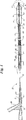
ここで図面を参照すると、図1は、本発明の好ましい実施形態を示すワイア導入型(over−the−wire)バルーンカテーテルを断面図にて示したものである。バルーンカテーテル20は、シャフトアセンブリ22及び末端付近で連結されたバルーンアセンブリ24を有する。従来のOTW型のマニホルドアセンブリ26がシャフトアセンブリ22の基端に連結されている。シャフトアセンブリ22は、基端30と末端32とを有する内側管28を備える。シャフトアセンブリの基端21は、シャフトアセンブリ22に接着されたマニホルドアセンブリ26内に延びる。ポリウレタン製のひずみ解放要素23がマニホルドアセンブリ26に装着され、シャフトアセンブリ22はポリウレタン製ひずみ解放要素23を通じてマニホルドアセンブリ26内に延びる。外側管34が内側管28の周囲に同軸に配されることにより環状膨張管腔37が形成される。
【0030】
バルーンアセンブリ24は基端側のバルーンくびれ38及び末端側のバルーンくびれ40とを有するバルーン本体部分36を備える。基端側のバルーンくびれ38は、接着剤44により外側管34の末端付近において外側管34に連結される。末端側のバルーンくびれ40は接着ボンド48により内側管28の末端32付近において内側管28に連結され、バルーン46の内部は環状膨張管腔37と流体移動可能に連通する。
【0031】
X線不透過性マーカバンド50が、バルーン本体36の下の所定の点においてシアノアクリレート系接着剤により内側管28に接着される。または、このマーカバンドは内側管の外表面に据え込むことが可能である。内側管28は、ガイドワイア(図に示されていない)のための通路を与えるガイドワイア管腔54を画定する。外側管34はバルーン46の内部と流体移動可能に連通する環状膨張管腔37を画定する。
【0032】
上記に述べたように、本発明のカテーテルは、比較的剛性の高い基端側の外側部分、より剛性の低い中間シャフト部分、及び最も剛性の低いテーパ形成された末端側の外側部分を有する外側管を好ましくは備える。カテーテルが末端方向に進むにしたがってより柔軟な材料が連続的に配される構成により、曲がりくねった脈管内を通過させるうえで最適な可推性及び可辿性の値が得られる。外側管状要素のこれらの部分の可撓性について、プレシジョンインスツルメント社(Precision Instruments)(トロイ、ニューヨーク州)(Troy,New York)により製造されるガーリー折り曲げ抵抗テスタ(Gurley bending resistance tester,Part No.4171−DT)を使用して試験を行った。この装置は、中心点を中心として旋回可能に支持された、バランスをとった振り子すなわちポインタから構成され、中心点の下方の3点において荷重をかけることが可能である。ポインタは左右いずれの方向にも自由に動く。特定の大きさの試料をクランプに取付ける。このクランプは、やはり左右に動く動力化されたアーム上の複数の位置の内の1つに置かれる。試験を行う際には、試料を羽根の上縁に対して押圧し、試料が曲がって羽根が解放されるまで振り子を動かす。試験は、最初は左方向、次いで右方向の2つの段階にて行われる。各方向において目盛りの指示値を測定し、結果を平均化する。この計器により、後述する向上した可辿性及び可推性を得るための、外側管状要素の構成部分間の相対的な可撓性の測定値が与えられる。
【0033】
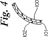
外側管34は、比較的高い剛性を有する、基端60と末端62とを備えた基端側の外側部分56を有する。この基端側の外側管は、ナイロン、バイヤー社(Bayer)から市販されるデュレタン(DURETHANE)などのポリアミド、デュレタン製ブレード、クリスタミド(CRISTAMIDE)製ブレードやポリエーテルエーテルケトン(PEEK)ブレードにて形成することが可能である。PEEK及びクリスタミドブレードの好ましい実施形態として可変PIC管があり、PICは約30〜100PICの範囲で変化して基端側外側管の全長にわたって変化する可撓性を与える。PICは好ましくは約50〜約80の範囲で変化することが好ましい。PEEKまたはデュレタン(ポリマ)製ブレードのブレード材料は、ステンレス鋼やニチノール(ニッケルとチタンの合金)から形成することが可能である。基端側外側部分56は、0.102cm(0.040インチ)〜0.114cm(0.045インチ)の外径と、0.0071cm(0.0028インチ)〜0.0112cm(0.0044インチ)の壁厚を有する。基端側外側部分56は、全長にわたって約500〜約1300の好ましいガーリー値を有する。好ましい範囲は約800〜約1200である。図4は、図1の4−4線に沿った、ブレード材料を有する基端側外側部分の断面図である。ブレードは、内側層100、ブレード層101、及び外側層102を有する。
【0034】
基端64と末端66とを備える中間シャフト部分58が基端側外側部分の末端62から末端側に延びる。中間シャフト部分58の剛性は基端側外側部分56の剛性よりも低い。中間シャフト部分58は、約81Dのデュロメータを有する、エルフ・アトケム(Elf Atochem)社から市販されるポリアミドから好ましくは形成される。中間部分の好ましいガーリー値は、約350〜約500であり、400〜450の範囲が好ましい。この中間シャフト部分58は、0.102cm(0.040インチ)〜0.114cm(0.045インチ)の外径と、0.0071cm(0.0028インチ)〜0.0112cm(0.0044インチ)の壁厚を有する。
【0035】
基端側外側部分の末端62は、ウレタン系接着剤や熱溶着にて中間シャフト部分の基端に接合される。基端70と末端72とを有する末端側外側部分68が、中間シャフト部分の末端66から外側管の末端44へと延びる。この末端側外側部分68は、基端側外側部分56及び中間シャフト部分58のいずれと比較してもより高い可撓性すなわち低い剛性を有する。末端側外側部分68の外径は、基端70における約0.114cm(0.045インチ)から末端72における約0.076cm(0.030インチ)へとテーパ状に形成される。この末端側外側部分68は、70Dのデュロメータを有するポリエーテルブロックアミド(PEBAX)にて形成される。テーパ形成された末端側外側部分は、好ましくは、基端において約70〜約90の、末端において約15〜約40のガーリー値を有する。すなわち、末端側外側部分の末端72は末端側外側部分の基端70よりも低い剛性を示す。中間シャフト部分の末端66は、ウレタン系接着剤や熱溶着により末端側外側部分の基端70に接合される。
【0036】
末端側外側部分の基端70内には約2.54cm(1インチ)の長さを有するニチノール製ブレード挿入要素74が配され、中間シャフト部分と末端側外側部分との接合部におけるひずみを緩和するとともに可捻性を低減する。このニチノール製ブレード74は、0.0025cm(0.001インチ)×0.0127cm(0.005インチ)の網目を有する。
【0037】
内側管28は、MarlexHDPEなどのポリエチレンにて形成される。内側管の基端30において、内側管28は、0.0609cm(0.024インチ)〜0.0660cm(0.026インチ)の外径、好ましくは約0.0635cm(0.025インチ)の外径と、0.0355cm(0.014インチ)のガイドワイアのための0.0457cm(0.018インチ)〜0.0495cm(0.0195インチ)の内径とを有する。この管腔はこのガイドワイアに適合するように構成されたものである。内側管28は、0.0066cm(0.0026インチ)〜0.101cm(0.04インチ)、好ましくは約0.0081cm(0.0032インチ)の壁厚を有する。壁厚に対する外径の比は、捩れが生ずる可能性を低減するうえで充分に小さくなければならない。
【0038】
内側管28が、外側管34の基端側外側部分の末端62と中間シャフト部分の基端64との接合領域を通じて末端方向に延びるにしたがって、内側管28の内径及び外径はより大きな径からより小さな径へといずれも漸減する。同様に、内側管の末端32において、内側管28の内径及び外径は、管が末端方向に延びるにしたがってより大きな径からより小さな径へと再び漸減する。
【0039】
図2に示されるように、一実施形態においては、末端側先端部76が、内側管の末端32に形成され、ここで内側管28はより大きな外径からより小さな外径へと末端方向に向けて漸減する。末端側のバルーンくびれ40は、接着領域においてウレタン系接着剤によって末端側先端部76に取り付けられる。末端側くびれ接着部の直ぐ末端側の領域は接着剤43にて埋められて滑らかな移行部をなす。この接着コーティングによって異なる基体間の接着性が向上する。
【0040】
基端側のカテーテルシャフト部分は、好ましくは約88.9cm(約35インチ)〜約114.3cm(約45インチ)、より好ましくは106.7cm(42インチ)の長さを有する。中間シャフト部分は、好ましくは約2.5cm(約1インチ)〜約7.6cm(約3インチ)、より好ましくは5.1cm(2インチ)の長さを有する。最も柔軟な末端側外側部分は、好ましくは約20.3cm(約8インチ)〜約30.4cm(約12インチ)、より好ましくは約25.4cm(約10インチ)の長さを有する。
【0041】
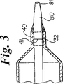
図3に示されるような別の好ましい実施形態においては、約45D〜65Dのデュロメータ、好ましくは約55Dのデュロメータを有するポリエチレン製末端側先端部80が、約63〜65Dのデュロメータを有する内側管の末端32に熱溶着または接着され、バルーンの末端側バルーンくびれ40は、内側管及びこれから延びる先端部の両者に対して接着されている。図3に示されるように、内側管と先端部との接合部41はバルーンの末端側くびれの下に位置する。ポリエチレン製末端側先端部80の外径はより大きな外径からより小さな外径へと末端側へ向かって漸減する。
【0042】
上記に述べたような柔軟な先端部を有する別の好ましい一実施形態においては、先端部の末端側の最後の1/2〜1mmの部分は、先端部とは異なる材料にて形成されて先端の延長部を形成する。詳細には、最後の1/2〜1mmの部分は柔軟な先端部の材料と比較してより耐久性の高い材料にて形成される。詳細には、このより耐久性の高い材料は、曲がりくねった解剖学的構造を辿ったり、留置されたステントを通じて進められる場合のような実際の使用に際して、変形や断裂を生じない。例として、この最後の1/2〜1mmは63Dのデュロメータを有するMarlex高密度ポリエチレンにて形成され、先端部分の最末端81における完全性が向上する。
【0043】
図2及び図3に基づいて上記に述べたように、本発明のカテーテルの先端部の構成は、バルーンカテーテルの先端部が管腔内の病変部や閉塞部を通過することを助けるような特徴を有するものである。この特徴としては、外径が小さくなるように構成されるか、または、外径が小径化した領域を有する、円錐状に形成された先端部が含まれる。この特徴として、更に、可辿性を向上させるために比較的柔軟な材料を使用することが含まれる。しかしながらこうした構成は、ストラットを有するステントの内腔に先端部を挿通するうえで最適とは云えない。図2及び3に示されるような先端部は、特に先端部が辿るガイドワイアが血管腔の湾曲部や屈曲部内にある場合にステントのストラットに引っ掛かりやすい。こうした屈曲部内では、ガイドワイアを辿る先端部は屈曲部の外縁に向けて偏倚し、ステントのストラットに容易に引っ掛かってしまう。本開示は、カテーテルの先端部が、留置されたステントに容易に通過されるようにカテーテルの先端部の形態を変化させるための手段を有する先端部、及びこうした先端部とガイドワイアとを組み合わせた構成の提供を目的とするものである。
【0044】
図5を参照すると、カテーテルの末端側先端部の形態を、血管腔の閉塞部に挿通するための第1の形態から、留置されたステントに挿通するための第2の形態に変化させるための手段を有する第1の実施形態が示されている。示された実施形態は、末端側くびれ114を有するバルーン112を通じて延びる内側管状要素110を備える。管状要素110は、バルーンくびれ114を通じて末端方向に延び、そこから末端側に突出して先端部116を形成する。管状要素110はガイドワイア(図に示されていない)を受容するためにこれを通じて延びる管腔111を有する。先端部116は、管状要素110の基端側部分と比較して小径化された内径及び外径を有する末端側部分118を備える。血管腔の閉塞部に通過させるための第1の形態においては、この先端部は図5に示されるような形態を有する。ステントに通過させるための形態に先端部を変化させるためには、先端部は、例として参照符合119として示される、先端118のネック状部分の基端側において離断される。この先端部の一部の離断を容易とするため、ミシン目などの強度の弱い部分を線状に設けてこうした部分の離断を助けることが可能である。第2の形態では、内側管状要素110の最末端の部分は末端119であり、図5において従来の構成と比較してより大きな断面積を有するとともにより丸みを帯びた部分として示されている。この構成により、ステントのストラットをくぐり抜けることが容易となり、ステント管腔を通じて更なる剛性を与える大径のガイドワイアを使用することにより、更にこれを容易とすることが可能である。
【0045】
図5の先端部の好ましい一実施形態においては、離断可能な先端部118は、0.0355cm(0.014インチ)の径を有するガイドワイアとともに使用するためのサイズに好ましくは形成された、小径化された管腔径を有するのに対し、その基端側の管腔は、0.0457cm(0.018インチ)のガイドワイアとともに使用するためのサイズに形成された径を有する。この構成は、例として、より剛性の高いワイアが必要とされる場合などの、ステントに通過させる用途以外の用途においても有用である。
【0046】
図6を参照すると、図5の先端部の構成の別の一実施形態が示されている。この構成では、バルーンは更に基端側くびれ114、及びこれを通じて延びる内側管状要素110を有する。ガイドワイア管腔111が内側管状要素110を通じて延びる。第1の形態においては、図6の先端部の構成は、血管腔の閉塞部により容易に挿通することが可能であるように、外径に沿ってほぼ円錐状をなす末端側先端部118を有する。この先端部の構成は、例として参照符合120によって示される部位において末端側先端部118を離断することにより、より容易にステントに挿通可能な第2の形態に変換または変化させることが可能である。この離断部位の基端側において、先端部はほぼ球根状の形状をなす部分121を有する。この残りの先端部の球根状断面は、先導端に引っ掛かることなくステントのストラットにくぐらせることが可能であるように構成されている。
【0047】
図7を参照すると、先端部116を形成する内側管状要素の最末端部の断面が、これを通じて延びるガイドワイア受容管腔111とともに示されている。この実施形態では、カテーテルの先端部の形態を変化させるための手段は、最末端において内側管状要素116上に巻き戻ることにより、ストラットに引っ掛かることなくステントに通過させることを容易とする球根状の先導端123を形成する柔軟な最末端の先端部122を有する。最末端の先端部122は、長手方向に薄く削ることにより、先端部がステントに接触する際の巻き戻りを容易とすることが可能である。
【0048】
図8を参照すると、カテーテルの先端部の形態を変化させる手段を有する別の一実施形態が示されている。図8の実施形態は、ガイドワイアを受容するための管腔111が内部を通じて延びる内側管状要素110を有する。先端部116がバルーン112の末端側くびれ114の末端側に形成される。この実施形態では、図に示されていない第1の形態は、ガイドワイアが挿通される際に直線状となる先端部116を有する。このガイドワイアを基端側に引き込むと先端部が図8に示されるような屈曲した形態に変化するように予備付勢することが可能である。先端部の屈曲部分の丸みを帯びた端部123は、先端部の先導端がストラットに接触して引っ掛かることがないため、ストラットに引っ掛かることなくより容易にステントに通過させることが可能である。
【0049】
図9及び図10を参照すると、先端部の構成の別の一実施形態が示されている。図9及び10の先端部の構成では、カテーテルの先端部の形態を変化させるための手段は、バルーン112及び末端側くびれ114を通じて延びる内側管状要素110を有するが、内側管状要素の外表面はバルーンの末端側くびれに接着されることはなく、末端側くびれ内に摺動可能に受容される。図9に示されるような第1の形態においては、内側管状要素110は末端方向に延び、閉塞した管腔に挿通するうえで適当な先端部116を形成する。図10は、形態が変化した状態にある図9の実施形態を示したものであり、内側管状要素110は基端側に引き戻されて、ステントに通過させるうえで有利な、カテーテルの最末端部のより丸みを帯びた形状を与える。内側管状要素110が上記の要領で利用可能であるためには、バルーンくびれ114と内側管状要素110の外表面との係合領域130において、膨張用流体がほぼ漏出しないようにこれらの間にシールが形成されなけらばならない。これは、公差に基づくかあるいはバルーンの末端側くびれを予備付勢することによって実現することが可能である。あるいは、バルーンの末端側くびれ内、すなわち内側管状要素の外表面上のバルーンの末端側くびれの下となる位置にO−リング式のシールを配することも可能である。
【0050】
図11を参照すると、末端側先端部の構成の別の一実施形態が示されている。図11の実施形態では、内側管状要素110はバルーン112の末端側くびれ114を越えて延びる末端側部分116を有する。この、末端側くびれを越えて延びる内側管状要素の部分は先端部を形成する。この実施形態の先端部は、先端部116の最末端134の基端側の所定の位置において側壁に設けられる孔132を有する。図11には示されていない第1の形態においては、ガイドワイア136は先端部116の末端を通じて延び、管腔内の閉塞部に通過させるうえでより好適な直線状の形態に先端部を保持する。先端部は、側壁に形成された孔132にガイドワイアを通過させることによって形態が変化し、先端部の、孔の末端側の部分が、留置されたステントにより容易に挿通することが可能な屈曲した形態をとる。
【0051】
図12を参照すると、末端側先端部116の別の実施形態が示されている。図12の実施形態では、末端側先端部116は、内部を通じて延びるガイドワイアを有する直線状の先端部として始めに構成されている。この先端部は、例として直線状態から45°の、直線状態に対する鋭角をなすように屈曲される屈曲先端部へと形態が変化するように構成されている。先端部は、屈曲する際に形態の変化を保つ金属ストリップやコイルまたはブレードを例として組み込むことにより、この角度に保持されるように構成されている。先端部は、直線状態から所定の鋭角をなして屈曲した状態においては、ステントに挿通されるための形態をとっており、ステント内で末端方向への動きに対する抵抗が生じた場合、カテーテルを基端において回転させることにより最末端134をステント壁から逸らせ、これを回転させつつステントを通じて進めることが可能である。この後ステントは、先端部116の、最末端先端部134の基端側の部分に当接する。
【0052】
図15を参照すると、先端部の形態の別の一実施形態が示されている。長尺の内側管状要素110の先端部116は、長尺の内側管状要素110の末端151に回転可能に固定された最末端部150を有する。最末端部150は、管腔111に挿通されるガイドワイアに対する長尺管状要素110の軸方向の運動に応じて回転するように構成されている。好ましい一実施形態においては、最末端部150の管腔は、その内部に少なくとも1つの螺旋状突起152を有し、これにより最末端部がガイドワイアに対して軸方向に動かされた場合にガイドワイアとの摩擦に基づき最末端部115の回転運動を生じる。先端部がステントの管腔を通過する際の先端部の若干の回転は、最末端先端部がステントのストラットに引っ掛かることを防止するうえで有効であるが、先端部が管腔閉塞部を通過する能力には影響を与えないものと考えられる。
【0053】
図20を参照すると、カテーテルアセンブリの先端部の形態を変化させるための別の一実施形態が示されている。図20の実施形態は膨張可能な袖部160を有する。袖部160は末端側先端部116の外周に固定されている。袖部は、袖部が先端部116の外周上に潰れた状態にある第1の位置から、ステントに通過させるうえでより適当な、球根状の形状をなす膨張位置へと膨らませることが可能である。図20に先端部の両方の形態を示した。この袖部は、内部にガイドワイアが置かれたガイドワイア管腔に流体を流すことにより、先端部116の壁に設けられた孔を通じて膨張すなわち拡張させることが可能である。ガイドワイアは、特に末端側部分において、カテーテルの末端から流出する流体に作用する抵抗によってこの流体の一部が膨張可能な袖部160内に流入するようなサイズに構成することが可能である。
【0054】
図13,14及び16乃至19を参照すると、ステントの管腔への挿通を容易とするために先端部をステントの内壁から逸らせるための手段を有するガイドワイアを備えた先端部及びガイドワイアの別の構成が示されている。先端部の最末端すなわち先導端をステントの壁から逸らせることにより、ストラットへの引っ掛かりが防止される。以下に述べる異なる実施形態のそれぞれはこのようにして機能するものである。
【0055】
図13を参照すると、ガイドワイア136が末端側先端部116から末端方向に延びている様子が示されている。ガイドワイアにはオフセットすなわちハンプ170が予備形成されている。末端側先端部116はオフセット170の直ぐ基端側に配置することが可能であり、ステントが収容された血管の屈曲部を通じて先端部及びガイドワイアがともに動かされる場合に、ハンプ170がステント壁に接触して先端部116をストラットから逸らせる。
【0056】
図17に示される別の動作モードでは、ガイドワイアはやはりハンプすなわち屈曲部170を有するが、この実施形態では、先端部116は、最末端部172が屈曲部すなわちハンプ170を部分的に覆うように配置される。これにより、図17に示されるように、ガイドワイアとともに末端方向に動かされる際に、ステントのストラットに接触することのない屈曲部が、先端部116の末端に形成される。ハンプすなわち屈曲部は1個が示されているだけであるが、同一または異なる平面上に複数のハンプすなわち屈曲部を有することも可能である点は認識されよう。
【0057】
図14を参照すると、ステント壁から先端部を逸らせるための手段を有する別のガイドワイアの構成が示されている。ガイドワイア136は複数の螺旋状コイル175を有する。螺旋状コイルの外径はガイドワイア管腔の径よりも大きいため、両者がステントの管腔を通じて末端方向に動かされる際に先端部116はステント壁から逸らされる。また、このコイル上に先端部が通過する際にコイルが真っ直ぐとなるようにコイルを構成することも可能である。コイルを真っ直ぐにする際、先端部は、各コイルを通過する都度、コイルの付勢に基づいて偏向され、ステント壁から逸らされる。この実施形態では、ガイドワイアのコイル部分は、カテーテルが通過しなければならないステントの長さ以上の所定の長さを一般に有する。
【0058】
図16を参照すると、図1のカテーテル20が概略的に示されている。カテーテルは、先端部116、及び先端部の末端を越えて末端方向に延びるガイドワイア136を有する。振動を与えるための手段180がカテーテルの基端に配され、ガイドワイアに連結されている。ガイドワイアに振動を与えることにより、ガイドワイアの末端は、カテーテルの先端部116がガイドワイア上に進められる際に振動するものと考えられる。振動のパターンを図16に破線138にて示した。この振動により、図に示されるようにカテーテルの先端部116はステント壁140から逸らされるものと考えられる。
【0059】
ガイドワイアの別の実施形態が図18及び19に示されている。ガイドワイア136は大径部190を有する。延ばされた位置では、ガイドワイア管腔とガイドワイアの外表面との間の間隙によりガイドワイアを辿ることが容易となる。図19に示されるように、ガイドワイア136が引き込まれた位置にある場合、ガイドワイア管腔とガイドワイア136の大径部190との間の公差は極めて厳密であるため、先端部はガイドワイアに緩くは適合しない。これにより、先端部はガイドワイアをより正確に辿り、先端部が偏向してステントのストラットに引っ掛かることが防止される。
【0060】
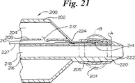
図21を参照すると、バルーン本体202、末端側先端部220、及び最末端222を有するバルーンアセンブリ200が示されている。バルーンアセンブリ200は、バルーン壁すなわちエンベロープ205及びバルーン内部を有する末端側の膨張可能な袖部すなわちバルーン206を更に有する。末端側バルーン206は、参照符合Aにて示される膨張していない第1の形態と、参照符合Bにて示される膨張させられた第2の形態とを有する。一実施形態においては、末端側膨張バルーン206は末端側先端部220に球根状の形状を与える。バルーン206は末端側先端部の領域に接着されたバルーンエンベロープ材料から形成することが可能である。バルーン本体202は、バルーン内部204、及び、示された実施形態においては、バルーン内壁208を有する。バルーンアセンブリ200は、末端側バルーン膨張管腔210、及び内側管216によって画定されるガイドワイア管腔218を有する。図に示された実施形態においては、バルーン内部204は第1の開口部212を介して末端側バルーン膨張管腔210と連通し、末端側バルーン膨張管腔210は第2の開口部214を介して末端側の膨張バルーン内部207と連通する。一実施形態においては、末端側バルーン膨張管腔210は、バルーン本体202を通じて延びる管によって画定され、例としてバルーン内壁208を有する。一実施形態においては、バルーン本体202の内部204は末端側膨張バルーン206と流体移動可能に連通し、膨張バルーン202によって末端側膨張バルーン206が膨らまされる。
【0061】
一実施形態においては、圧力下の膨張流体が供給される際には末端側膨張バルーン206の膨張を可能とし、膨張流体圧がない場合には末端側膨張バルーン206からの膨張流体の流出を防止するために弁が機能する。図21に示された実施形態においては、弁プラグ235が、弁制御ワイア227の末端に配され、弁座224の近傍に配置される。弁プラグ225を引き戻すことによりバルーン内部204から末端側バルーンの内部206への流体の流れが可能となる。弁プラグ225を弁座224に当接するように進めてバルーン206と206との間の流体の流れを防止することが可能である。一実施形態においては、弁プラグ225は、例としてバネによって末端方向に付勢されて弁座224に押圧される。弁プラグ225が引き込まれている場合、バルーン202を末端側バルーン206とほぼ同時に膨張させることが可能である。弁プラグ225が弁座に着座している場合、末端側バルーン206を膨張状態に保ったまま、バルーン202を萎ませることが可能である。
【0062】
一実施形態においては、逆止弁を使用して、末端側膨張バルーン206内への加圧流体の流入は可能であるが、末端側膨張バルーン206は逆止弁を通じてあくまで徐々に萎むように構成することが可能である。上記の実施形態において逆止弁と呼ばれる弁では実際は第2の方向への流れが可能であるが、第1の主たる方向における場合と比較して流速は大幅に遅い。一実施形態では、末端側の膨張バルーン206は、加圧下で供給される注入流体がない場合にバルーンが徐々に萎むように構成される。
【0063】
図21から理解されるように、膨張させられた末端側膨張バルーン206の球根状の形状は、最末端222をステントの外縁または内壁から逸らせるうえで機能する。
【0064】
実際の使用に際しては、末端側膨張バルーンに対して別個の膨張管腔を有する実施形態では、バルーンアセンブリをステントの近傍に進めることが可能である。末端側膨張バルーンを膨張させて大きな球根状の形状を得ることが可能であり、これにより最末端222をステントを通じて更に進めることが可能である。最末端222がステントを通じて充分に進められた後、末端側膨張バルーンは、膨らんだ状態または萎んだ状態に保つか、あるいは透過膜や小さな脱出孔などの制御可能な手段によって制御された速度で萎ませることが可能である。別個の末端側バルーン膨張管腔を有する実施形態では、一方法において、末端側膨張バルーンの膨張及び収縮に対して別個の膨張管腔を利用する。
【0065】
実際の使用に際し、バルーン本体202と末端側膨張バルーン206との間に共有流体空間を有する実施形態においては、挿通されるべきステント内に最末端222を進めるのに先立って、バルーン本体202及び末端側膨張バルーン206はいずれも膨らまされる。一方法においては、最末端222がステント内に充分に進められた後、バルーン本体202及び末端側膨張バルーン206は自発的に萎むか、あるいは膨張流体を除去することによって能動的に萎まされ、バルーン本体202をより容易にステント内に進入させることが可能である。バルーン本体202と末端側膨張バルーン206との間に共有流体空間を有し、更に逆止弁を有するとともに末端側バルーン206から膨張流体が制御して抜かれるような実施形態においては、バルーン本体202及び末端側バルーン206は最末端222をステント内に進めるのに先立って膨らませることが可能である。最末端222がステント内に充分に進められた後、膨張流体の圧力を取り除くことが可能であり、バルーン202は萎むが、末端側バルーン206は膨張状態に保たれる。一方法においては、末端側バルーン206は、末端側バルーン206に配される半透膜や脱出孔などの膨張流体を脱出させるための手段を介して膨張流体が脱出することにより、制御された速度で萎む。バルーン本体202と末端側バルーン206との間の共有流体空間内において逆止弁を使用することにより、カテーテルの全長にわたって延びる別個の膨張管腔または管を用いる必要がなくなる。これによりカテーテルの全体の断面積及び複雑さが低減される。詳細には、共有流体空間の使用により、末端側膨張バルーン206は末端側バルーン202に供給される流体を使用して効果的に膨らませることが可能である。
【0066】
図22を参照すると、バルーン末端側くびれ232、接着領域234、及び内側管240を有するバルーンアセンブリ230が示されている。内側管240は、管壁244及び末端部231を有し、最末端238において末端側で終端する。示された実施形態では、複数の長手方向スリット236が最末端238近くの管壁244を通じて延びるが、スリットが設けられていない末端領域241には形成されていない。複数のスリット236の間には複数のフラップ246が形成される。スリットが設けられていない領域241はスリット236の末端側に延びてスリットが設けられていない最末端を形成する。この実施形態では、スリットが設けられていない領域241は横方向に切ってこれを除去することにより、最末端にスリット236が現れる。図22では、最末端238は、管244のものとほぼ同様の断面形状及び径方向の広がりを有し、更にスリットが設けられていない領域241を有する第1の状態にて示されている。一実施形態では、末端部231はニチノールや当業者にはよく知られている形状記憶ポリマなどの形状記憶材料にて形成される。
【0067】
図23を参照すると、バルーンアセンブリ230は、スリットのない領域241が除去され、末端部231の断面積及び径方向の広がりが、図22に示される末端部231及び内側管244の全長の大部分と比較して増大している第2の状態にて示されている。図23では、カールして外側に延出した形態を有するフラップ246が示されている。フラップ246は、管244と比較して径方向の広がりが大きいことにより、ステントに接近する際の最末端の断面積が大きくなる。
【0068】
フラップ246により大きくなった最末端の断面形状は、挿通されるべきステント内で最末端238が引っ掛かることを防止するうえで機能する。フラップ246は、特に比較的可撓性の大きい柔軟な多数の角部248を有する場合に、ステントに引っ掛かった際の抵抗が小さい最末端を与える。具体的には、可撓性を有する最末端角部248はステント壁や周縁に引っ掛かった場合にバルーンに向けて折れ曲がる。すなわちバルーンアセンブリ230を、最末端角部248がステントに引っ掛かる場合においてもステントを通じて末端方向に進めることが可能である。同様に、フラップ246がカールすることにより増大するスリット幅のため、スリットを有さない末端部と比較して末端部231の強度が低下する。全体として相対的に強度が低下した末端部により、ステント壁や周縁に引っ掛かった場合に、より柔軟すなわち可撓性の大きな末端領域が与えられ、末端部231が引っ掛かった場合においてもバルーンアセンブリ230を更に末端側に進めることが可能である。この場合、末端部231のフラップ246はバルーンに向かって基端方向に屈曲し、バルーンアセンブリ230が更に進められた時点で末端側にカールするものと考えられ、フラップ246とステントとの引っ掛かりは、フラップがステントによる障害から解放された時点でなくなる。
【0069】
実際の使用に際し、最末端においてスリットが設けられない実施形態では、ステントの挿通に困難が生ずる時点までバルーンアセンブリ及びカテーテルを通常の要領で使用することが可能である。その時点でカテーテルを引き込み、末端部231のスリットのない部分を切離することにより、最末端にまでスリットが延びた末端部が露出する。次いでカテーテルを、挿通されるべきステントにまで進める。形状記憶材料にて形成されたフラップ246は、体温に充分に曝されると図23に示される外側に広がった形態をとる。
【0070】
図24を参照すると、バルーン末端側くびれ252、末端領域260を有する内側管254、最末端領域262、及び最末端266を備えたバルーンアセンブリ250が示されている。内側管254は複数の長手方向スリット264が設けられた内側管壁256を有する。複数の長手スリット264は、末端領域260を通じて延び、スリット間には複数のフラップ270が形成される。好ましい一実施形態においては、最も内側の管258が、内側管254の内部に摺動可能に配される。内側管258は例として接着剤の使用により、好ましくは最末端領域262において内側管254に接合される。好ましい一実施形態においては、内側管254及び最も内側の管258は、末端領域260の大半の内部に摺動可能に配されるが、最末端領域262において互いに対して固定されている。好ましい一実施形態においては、末端領域260は高密度ポリエチレンなどの可撓性の高分子材料にて形成される。最も内側の管258は、これを通じて設けられたガイドワイア管腔268を好ましくは有する。別の一実施形態においては、最も内側の管258を、内部に管腔を有さない最も内側のシャフトまたはワイア状要素によって置き換えることが可能である。
【0071】
図25を参照すると、断面形状すなわち径方向の大きさが増大した第2の形態にある図24のバルーンアセンブリ250が更に示されている。内側管254に対して最も内側の管258を引き戻すことにより、フラップ270は末端領域260において径方向の大きさが拡大する。使用に際して、バルーンアセンブリ250をステント近傍の所定の位置に進めることが可能である。最も内側の管258を内側管254内に引き込むことにより、図25に示されるように末端領域260が拡大する。増大した末端領域260の径方向の大きさ及び断面積は、最末端266をステント壁及び周縁から逸らせるうえで機能する。最末端266が充分に進められた時点で、最も内側の管258を内側管24に対して進めることにより、フラップ270は図24に示される小さな断面形状に戻る。
【0072】
図26を参照すると、マニホルド308、シャフト309、及びバルーンアセンブリ302を有するバルーンカテーテル300が示されている。シャフト309は、末端孔307において終端する第1の管腔306が内部に設けられた第1の内側管すなわちガイドワイア管304を有する。マニホルド308は内部にテーパ形成された管腔311が設けられた、基端側テーパ形成領域310を有する。マニホルド308はマニホルド308を連結要素312に連結する螺刻領域314を有する。一実施形態では、第1の内側管304は約0.00889cm(0.035インチ)の内径を有する。別の一実施形態では、第1の内側管304は約0.0457cm(0.018インチ)の内径を有する。
【0073】
図27を参照すると、第2の内側管としてのガイドワイア管316、及びその内部に設けられる第2のガイドワイア管腔318を有する内側管アセンブリ320が示されている。内側管アセンブリ320は、内部に基端側管腔324が設けられるとともに第2のガイドワイア管腔318と流体移動可能に連通した基端側アダプタ322を有する。第2の内側管316は第1のガイドワイア管304内に受容されるようなサイズに形成されている。基端側アダプタ322は、マニホルド308の基端側テーパ形成部310内に受容されるようなサイズに形成されている。一実施形態では、第2の内側管316は約0.0355cm(0.014インチ)の内径を有する。一実施形態においては、第2の内側管316は、第1の内側管304の長さに適合した所定の長さを有し、第2の内側管316は第1の内側管304内に完全に進められた場合に第1の内側管の末端孔307から末端側に延出する。
【0074】
使用に際しては、バルーンカテーテル300を患者の血管系内に進めてバルーンアセンブリ302を標的部位の近傍に配置する。この時点で、バルーンアセンブリ302を血管のより遠位の領域及び/または血管のより閉塞した領域へと更に進めることが望ましい場合がある。この、より遠位の領域及び/またはより閉塞した領域においては、より小型のガイドワイアの使用を必要とする。より小型のガイドワイアの使用は、曲がりくねった血管領域内において狭隘な病変部に通過させるうえで、または所定位置に到達させるうえで有用であるが、このガイドワイアは第1のガイドワイア管腔306の内径よりも大幅に小さくなる。この時点において、術式を行う医師は第2のより小型のガイドワイアを必要とする場合がある。この第2のより小型のガイドワイアはより小さな内径を有するガイドワイア管から向上した支持を受ける。次に第1のガイドワイアをバルーンカテーテル300から引き抜き、内側管アセンブリ320をバルーンカテーテル300の第1のガイドワイア管腔306内へと末端方向に進める。第1の内側管304内に置かれる第2の内側管316には、より小さな第2のガイドワイア管腔318が設けられている。第2のより小径のガイドワイアをバルーンアセンブリ302の末端側の所定位置に到達するまで第2のガイドワイア管腔318を通じて進めることが可能である。この第2のより小径のガイドワイアは標的部位へと更に進めることが可能である。第2のより小径のガイドワイアは、第2の内側管316内に設けられたより小さな第2のガイドワイア管腔318によって、座屈に対する向上した支持を受けることが可能である。
【0075】
一実施形態においては、第2の内側管は、これを包囲する第1の内側管から末端側に延びることが可能である。第2の内側管は、第1の管から末端方向に延びる第2の管の長さを変化させることが可能であるように調整される軸方向の位置を有することが可能である。この構成により、末端方向に突出する最も内側の管が与えられ、その内部にガイドワイアが配される場合と配されない場合とがある。この最も内側の管を末端方向に進めることにより、狭窄部に挿通する場合に有利な小さな断面形状が与えられる。この最も内側の管を基端方向に引き込むことにより、必要に応じて大きな断面形状が与えられる。
【0076】
詳細には、本発明のカテーテルは、ワイア導入型カテーテル、固定ワイア型カテーテル、及び単独操作者交換型カテーテルをその開示の範囲内に含むことが認識される。
【0077】
以上の説明文においてこの文書に含まれる発明の多くの利点について述べた。しかしながら、この開示は多くの意味においてあくまで説明を目的としたものである点は理解されよう。発明の範囲を越えることなく、特に構成要素の形状、大きさ、及び配置といった細部において変更を加えることが可能である。発明の範囲は無論のこと特許請求の範囲を記載する文言によって定義されるものである。
【図面の簡単な説明】
【図1】本発明の好ましい一実施形態を示すカテーテルの断面図。
【図2】図1のカテーテルの末端側先端部領域の好ましい一実施形態の部分断面図であって、内側管にて形成される先端部を示す図。
【図3】図1のカテーテルの末端側先端部領域の第2の好ましい実施形態の部分断面図であって、内側管のより剛性の高い末端とより可撓性の高い末端側先端部との間の移行部を示す図。
【図4】図1の4−4線に沿った断面図。
【図5】離断可能な小断面積の末端部及び残される丸みを帯びた部分を有する第1の先端部の構成の部分断面図。
【図6】離断可能な円錐状先端部及び残される球根形状の基端側先端部を有する図5の実施形態に類似した別の実施形態の部分断面図。
【図7】先端部上に折り返されて、より球形の断面を与える最末端部を有する先端部の一実施形態の部分断面図。
【図8】屈曲した形態に曲げることが可能であることにより留置されたステントへの挿通を容易とする先端部の構成の部分断面図。
【図9】病変部に容易に挿通可能である延ばされた位置へと延長することが可能な内側管状要素を有する先端部の構成の部分断面図。
【図10】管状要素が、留置されたステントに通過させるためのより丸みを帯びた形状を与える、引き込まれた位置にある図9の先端部の構成の部分断面図。
【図11】先端部の壁に孔が設けられることにより、第1の形態においては先端部はその末端を通じてガイドワイアが延びることにより直線状をなし、第2の形態においては、ガイドワイアは前記孔を通じて延びて、ステントに通過させるための屈曲した末端側先端部を与えるような先端部の構成の部分断面図。
【図12】屈曲可能な末端側先端部であって、図に示されるような屈曲位置においてはカテーテルを回転させることによりステントに通過させることが容易である末端側先端部を有する別の先端部の構成を示す部分断面図。
【図13】ステントの壁に接触して先端部を壁から逸らせるオフセット屈曲部すなわちハンプを有するガイドワイアの構成を示す部分断面図。
【図14】複数のコイルであって、先端部が該コイル上に通過させられる場合に、留置されたステントから先端部を逸らせるコイルを有するガイドワイアの構成を示す部分断面図。
【図15】回転可能に取り付けられた最末端部であって、ガイドワイアに沿った摩擦に基づいて回転する最末端部を有するカテーテルの先端部の構成を示す部分断面図。
【図16】基端から振動させられるガイドワイアを有するカテーテルを示す概略図。
【図17】ハンプを有し、先端部が該ハンプの一部を覆って配置されることによりステントのストラットに引っ掛かることが防止される別のガイドワイアの構成を示す部分断面図。
【図18】ガイドワイア上に球根状の末端部を有するガイドワイアの構成を示す部分断面図。
【図19】球根状部分に対する公差が厳密であることによりカテーテルの先端部がステントのストラットに引っ掛かることを防止する、引き込まれた位置にある図18のガイドワイアアセンブリを示す部分断面図。
【図20】膨張可能な袖部であって、膨張することによりステントに引っ掛かりにくいほぼ球根状の形状を与える袖部を有する先端部の構成を示す部分断面図。
【図21】膨張可能な球根状先端部を有するカテーテル末端部の部分縦断面図。
【図22】予め緊張が与えられるとともに長手方向のスリットが設けられた末端部を有する内側管の拡張前の状態が斜視図にて示された、カテーテルの末端部の部分縦断面図。
【図23】予め緊張が与えられるとともにスリットが設けられた先端部の拡張後の状態を示す図22のカテーテル先端部の部分縦断面図。
【図24】末端にスリットが設けられた管と、この管の内部に摺動可能に配されてその末端に固定された別の管とを有する膨張可能なカテーテル末端部の部分縦断面図。
【図25】内側の管が引き込まれることにより末端部が径方向に拡大した図24の膨張可能なカテーテル末端部の部分縦断面図。
【図26】マニホルド及び内側ガイドワイア管を有するカテーテルの部分縦断面図。
【図27】図26のマニホルド及び内側ガイドワイア内に摺動可能に受容されるように適合された最も内側のガイドワイア管の部分縦断面図。[0001]
(Field of Invention)
The present invention relates generally to medical devices used in combination with guide elements. More particularly, the invention relates to an intravascular catheter having an improved tip and guidewire lumen. The present invention has means for changing the shape of the distal most distal tip for optimal placement over the lesion or through the stent. The present invention further includes an innermost guide wire tube disposed within the inner guide wire tube.
[0002]
(Background of the Invention)
Intravascular disease is generally treated by relatively minimally invasive catheter-based techniques such as percutaneous transluminal angioplasty (PTA) and percutaneous transluminal coronary angioplasty (PTCA). Catheter-based treatment and diagnostic techniques include atherectomy, laser irradiation, ultrasound imaging, and the like. These therapies are well known in the art, and usually a balloon catheter or other catheter with a treatment element located near the end of the catheter, along with a guide wire and other cases as needed. Used in combination with other intravascular elements. A typical balloon catheter has a long shaft with a balloon attached near the distal end and a manifold attached to the proximal end. In use, the balloon catheter is advanced over the guide wire and the balloon is placed in contact with the stenosis of the diseased blood vessel. The balloon is then inflated to widen the stenosis of the blood vessel. More recent techniques for treating intravascular disease use a balloon dilatation catheter to deliver and place a stent into a stenosis within the lumen of a blood vessel. The stent generally has a generally cylindrical shape with a lumen extending therethrough. When the stent is placed at the lesion site, it is expanded from a deflated state to a swollen state by a balloon, thereby physically preventing the lumen of the blood vessel from closing over the entire length of the stent. The wall of the stent is preferably made of a metal material and has a plurality of interconnected struts with a certain regularity between which spaces are interposed. These spaces open through cylindrical walls. Such a stent is disclosed in US Pat. No. 5,449,373 and International Patent Application Publication No. WO 96/03092, the entire disclosure of which is incorporated herein by reference. A catheter specifically constructed to deliver such a stent is disclosed in US Pat. No. 4,950,227, the disclosure of which is also incorporated herein.
[0003]
There are basically two types of balloon catheters used in combination with guidewires. That is, an over-the-wire (OTR) catheter and a single-operator-exchange (SOE) catheter. The construction and use of OTW catheters and SOE catheters are both well known in the art. An example of an OTW catheter is shown in US Pat. No. 5,047,045, assigned to Arney et al. And assigned with this application, the disclosure of which is hereby incorporated by reference. An example of an SOE balloon catheter is disclosed in US Pat. No. 5,156,594, assigned to Keith and assigned with this application, the disclosure of which is hereby incorporated by reference.
[0004]
PTA and PTCA catheters are preferably configured such that pushability, trackability, and crossability are optimized. Inducibility is defined as the ability to transmit force from the proximal end of the catheter to the distal end of the catheter. Traceability is defined as the ability to travel in a bent vessel. Permeability is defined as the ability to pass a balloon catheter through a stenosis within a vessel.
[0005]
The traceability of a particular catheter configuration is analyzed in the traceability of the distal end portion of the catheter. This is because this part has to follow the guide wire through a small tortuous blood vessel in order to reach the stenosis site to be treated. It has been shown that a more flexible end portion improves traceability. Furthermore, it has been shown that in the transition of the catheter shaft from a rigid proximal part to a softer distal part, the joint between these two shaft parts of different flexibility is easily twisted. ing. Also, by increasing the flexibility of the distal portion, this portion of the catheter is less likely to be pushed from the proximal end of the catheter.
[0006]
Permeability is related to the traceability of a particular catheter configuration in that it is affected by the flexibility of the distal portion of the catheter, but moreover, in the area of narrow lesions, catheter permeability is It is influenced by the configuration of the distal end portion of the. The distal tip includes a distal region of the balloon that follows the guide wire and a portion that is first allowed to pass through the stenosis in the most distal portion. That is, the name of the invention, whose disclosure is incorporated herein, is an application filed on October 15, 1997, which is “wire-introducing catheter with improved traceability”. A great deal of effort has been expended in providing a tip that has improved portability, such as that disclosed in co-pending US patent application Ser. No. 08 / 950,864.
[0007]
Although the tip configuration as described above has improved traceability and portability, it has been shown that such a tip configuration is not appropriate for the procedure performed to deploy and expand the stent. It was. More particularly, in the initial placement of the stent, the stent is pre-mounted on a deflated balloon, and the improved tip configuration allows the tip to provide a leading end through the lesion. It is easy to place the stent over the part. However, at this point, it is common practice to expand the stent by inflating the balloon and then deflating it. The balloon catheter is then pulled back a predetermined distance over the guidewire and the stent placement is evaluated by fluoroscopy. In order to properly lock the stent against the vessel wall, it is often necessary to move the balloon again distally through the stent and later inflate the balloon within the stent. In such cases, the balloon catheter must be moved distally over the guidewire to place the balloon over the stent. In these situations, the tip must first pass inside the stent. The tip having a configuration that improves the permeability of the balloon catheter through the lesion may be caught by the stent struts when passing through the stent, making it difficult to expand the stent later. This is particularly noticeable at the bend where the leading end of the tip is caught on the outer wall of the bend, but this is because the guidewire tends to be pressed against the outer diameter of the bend. This is because the most distal end is urged in the same direction when tracing the curve.
[0008]
The above-mentioned problems related to the configuration of the distal end, which is optimized in terms of permeability to the lesion but has difficulty in inserting into the stent, cause the lesion located on the distal side of the stent in the same artery to be It is also a problem when treating. In order to dilate the more distal lesion, the balloon dilatation catheter to be used must first be passed through the lumen of the stent if the stent is placed in the artery prior to this. Therefore, the same problem that the tip portion is caught by the strut occurs.
[0009]
Therefore, there is provided a configuration of a catheter having a distal end portion that is configured to pass through a lesion and can be converted into or changed to a second form suitable for passing through the stent lumen without being caught by a strut. So far, this requirement has not been met. The present invention provides such a tip configuration, i.e., a tip configuration combined with a guidewire having means for changing the configuration of the distal end portion of the catheter, thereby allowing passage through the lumen of the stent. In this case, the interaction between the strut and the tip, which is a problem, is prevented.
[0010]
(Summary of Invention)
The present invention relates to a catheter assembly having a treatment element proximate to a distal end for performing endovascular treatment of a blood vessel at a predetermined location within the lumen of the blood vessel. Preferred embodiments include wire-introduced balloon catheters described in detail herein, but balloon expandable catheters include any known balloon catheter, such as a fixed wire catheter or a single operator replaceable catheter Is included. Further, although the treatment element disposed near the distal end of the catheter disclosed herein is a balloon, any other known treatment element may be attached to the catheter to practice the invention disclosed herein. Is possible.
[0011]
Wire introducer catheters generally have an elongate tubular element having a proximal end and a distal end through which a guide wire receiving lumen extends. The elongate tubular element is coaxially disposed within an outer tubular element that also extends over a portion of the entire length of the inner tubular element. The inner tubular element extends distally beyond the outer tubular element, and an inflation lumen is formed by an annular space between the two tubular elements. A balloon having a proximal end and a distal end is attached in the vicinity of the distal end of the catheter, and a predetermined internal volume communicating with the inflation lumen so as to allow fluid movement is formed therein. In a preferred embodiment, the balloon is sealably attached at its proximal end near the distal end of the outer tubular element and distally toward the distal end of the inner tubular element extending beyond the outer tubular element and sealably connected thereto. Extend to. The proximal end of the catheter has a hub assembly that provides a guidewire receiving port extending into the lumen of the inner elongate tubular element and an inflation port in fluid communication with the annular inflation lumen.
[0012]
The catheter has a tip, which in a preferred embodiment is the portion of the catheter that is distal to the balloon and is generally formed by a portion of the inner tubular element having a guidewire lumen extending therethrough. Yes. This tip is configured to be optimal in helping the catheter initially follow the guidewire and further through the lesion to be dilated. That is, the flexibility and shape of the tip is modified to facilitate insertion. For example, the distal end may be formed in a neck shape so that it has a smaller diameter than the diameter of the proximal side of the inner tubular element, or it may be directed toward the distal end so that it can be easily inserted into a blocked blood vessel. It is possible to form a conical shape having a reduced outer diameter.
[0013]
One embodiment of the present invention is a catheter tip assembly for insertion through both a vessel lumen occlusion and an indwelling stent, (a) having a proximal end and a distal end and having a guide wire receiving tube therethrough. An elongate inner tubular element extending from the cavity; and (b) a balloon for performing a therapeutic treatment near the end of the inner tubular element, the distal end of the inner tubular element extending distally beyond the balloon. A catheter tip, which provides a leading end for following a guide wire extending therethrough, and (c) from a first configuration for insertion through the occlusion of the vessel lumen, Means for changing the configuration of the catheter tip to a second configuration for insertion through an indwelling stent, comprising: The means includes a distal end tip portion that can be cut off at a perforation formed in the catheter tip portion, and the catheter tip portion has a second configuration by cutting off the distal end tip portion. The distal end of the catheter tip in the second configuration has a larger cross-sectional area than the distal end of the catheter tip in the first configuration; A catheter tip assembly is provided.
Different embodiments of the present invention provide a tip configuration and a tip and guide wire configuration that, when in the first configuration, are optimal for passage through a lesion. The tip or the combination of the tip and the guide wire, when in the second configuration, is not applied to the placed stent because the tip does not get caught by the strut in the stent placed in the bent portion of the blood vessel. Ideal for passing through.
[0014]
In a first series of embodiments, the tip assembly changes the configuration of the catheter from a first configuration for insertion through an occlusion within a vessel lumen to a second configuration for insertion through an indwelling stent. Means for making it happen. In one embodiment, the proximal distal portion of the distal portion is left having a detachable distal distal portion that is removed after treatment of the occlusion and is more suitable for passage through the stent. The remaining portion of the tip has a more bulbous shape in cross-section or has a larger diameter lumen used with a larger diameter guide wire.
[0015]
In another embodiment, the distal end tip changes shape by folding the distal end onto the inner tubular element, and in the first configuration, the tip passes through a lesion or occlusion. In the second embodiment, the folded portion forms a tip having a more bulbous shape that is not easily caught by the strut. Alternatively, the tip portion can be configured to change from a linear form to a bent form that facilitates insertion into a bent stent.
[0016]
In another embodiment, the inner tubular element is configured to be slidable within the catheter or, when extended, provides a tip that can be easily inserted through the lesion but is retracted. It is possible to use a sheath having a more bulbous shape, that is, a rounded shape so that the probability that the remaining tip portion is caught by the strut of the stent becomes low.
[0017]
Finally, the distal end of the catheter can be configured to have a distal end extending distally of the balloon that is rotatably attached to the inner tubular element. At least one helical protrusion can be formed in the lumen of the tip portion in the lumen of the tip portion that is rotatably attached. When the catheter is moved relative to the guide wire inserted therethrough, the friction between the spiral protrusion and the guide wire causes the distal end portion to rotate, and the probability that the distal end portion is caught by the stent strut is reduced.
[0018]
In a second series of embodiments, the guide wire configuration used with the catheter tip assembly is such that the distal tip of the catheter is a strut of the stent when the guide wire is selectively positioned relative to the tip. The guide wire configuration keeps the guide wire in contact with the stent while the tip is deflected or pulled away from the strut. In this configuration, a guidewire having a pre-formed bend at a selected location or having one or more helical coils that are placed within the lumen of the stent when the catheter is inserted through the stent. Forming. Alternatively, the guidewire can have a bulbous portion that, when retracted, provides a more bulbous cross-section at the distal tip to prevent the catheter tip from catching on the stent struts. It is.
[0019]
In another embodiment, the guide wire may be vibrated from the proximal end of the catheter, thereby causing the portion of the guide wire on the distal side of the balloon to vibrate in a pre-selected pattern, thereby being caught on the stent struts. It is possible to deflect the distal end of the catheter.
[0020]
The distal tip of the catheter can be configured to have an inflatable sleeve that surrounds the distal end of the tip. The sleeve portion can communicate with the guide wire lumen through a hole provided in the wall of the distal end portion so as to be fluid-movable. By injecting fluid into the guidewire lumen and creating a sufficient pressure drop along the guidewire across the tip, a portion of the inflation fluid fills the sleeve and passes through the stent lumen as it passes through the stent lumen. Gives the overall tip shape to a more bulbous shape that is less likely to get caught by struts.
[0021]
The present invention includes a balloon catheter having a first balloon and a second distal inflatable balloon or sleeve disposed on the distal side of the first balloon. The balloon on the second end side can be inflated to increase the cross-sectional shape of the most distal region, that is, the maximum size in the radial direction. By increasing the cross-sectional shape of the distal end region, the distal end can be displaced from the inner wall or end of the stent. In one embodiment, the interior of the first balloon is in fluid communication with the interior of the distal balloon. These embodiments have the advantage of not requiring a separate inflation lumen for the distal balloon, which would otherwise require a tube or lumen extending the entire length of the catheter.
[0022]
In one embodiment, a check valve can be placed between the first balloon and the distal balloon to prevent the distal balloon from deflating rapidly. In this embodiment, by inflating the first balloon, the second balloon is also inflated, and the distal balloon can be kept inflated when the first balloon is deflated. In another embodiment, a controllable valve is disposed in the fluid space between the first balloon and the distal balloon. By opening this controllable valve, fluid can flow from the first balloon to the distal balloon. Fluid flow between the distal balloon and the first balloon can be blocked by operating this valve. Some such valves are switchable between a first open position and a second closed position. Another valve is biased to remain in the closed position and can be operated by the pull wire to be kept in the open position when the pull wire is retracted. In this embodiment, releasing the pull wire returns the valve to the closed state.
[0023]
Some balloon catheters employing the present invention have a distal region with a tube having a wall and a lumen extending therethrough. The tube is pre-tensioned to take the second form after insertion into the body. One preferred end region is formed of a shape memory material, such as nitinol or shape memory alloy, and expands to the maximum radial size of the end region when body temperature is reached. Some such catheters have a distal region with a plurality of flaps in a longitudinal slit that curl outward when the temperature is increased by warm body fluids. Some of these catheters have an outermost end provided with a plurality of slits that terminate before the end. In this embodiment, when the operator cuts off the extreme end, the slit in the longitudinal direction is exposed, and the tip expands when it comes into contact with warm body fluid.
[0024]
One catheter according to the invention comprises a distal region having an inner tube and an innermost tube slidably disposed within the inner tube. This innermost tube can be secured to the inner tube at the extreme end. In this embodiment, the distal region has a plurality of longitudinal slits with flaps formed therebetween. The innermost tube can be retracted proximally, thereby pulling the innermost tube disposed around the innermost tube and the innermost tube. Accordingly, the flaps between the slits in the longitudinal direction bulge outward, so that the maximum radial size of the end region, that is, the cross-sectional shape becomes larger. This outwardly projecting distal region flap can serve to deflect the distal end of the catheter away from the stent wall and end.
[0025]
In another embodiment of the invention, a balloon catheter is provided having a first inner guidewire tube having a first guidewire lumen extending therethrough. This catheter has a manifold with a tapered region on the proximal side disposed therein. It is also possible to place a second smaller diameter inner tube having a second smaller diameter guide wire lumen. The second guidewire tube can have a tapered proximal adapter adapted to be slidably received within the proximal region of the balloon catheter manifold. The inner tube assembly thus provided can be placed in the first guide wire tube and manifold, thereby providing a smaller diameter guide wire lumen. In use, the balloon catheter can be used in combination with the first guide wire where a first large diameter guide wire is desired. If it is desirable to use a second smaller diameter guide wire, the first guide wire can be retracted. This allows the inner tube assembly with the second inner tube placed within the first inner tube to be advanced through the catheter. With the second inner tube positioned in this manner, a second small diameter guide wire can be advanced through the second inner tube and further through the distal end of the balloon catheter. This second smaller diameter inner tube provides improved support for small diameter guide wires and improved resistance to buckling. In one embodiment, the second smaller diameter inner tube extends distally from the distal end of the first tube disposed around when the second tube is fully advanced into the first tube. It has a sufficient length.
[0026]
(Detailed description of the invention)
Many of the other objects and advantages associated with the present invention will be readily understood by reference to the following detailed description based on the accompanying drawings. Like elements are designated with like reference numerals throughout the drawings.
[0027]
The following detailed description should be read with reference to the drawings, in which like elements in different drawings are identically numbered. The drawings are not necessarily to scale, but are illustrative of selected embodiments and are not intended to limit the scope of the invention.
[0028]
Examples of configurations, materials, dimensions, and manufacturing methods are shown for selected elements. All other elements are well known to those skilled in the art. Those skilled in the art will recognize that for many of the examples shown, there are still other suitable examples available.
[0029]
Referring now to the drawings, FIG. 1 is a cross-sectional view of an over-the-wire balloon catheter illustrating a preferred embodiment of the present invention. The
[0030]
Balloon assembly 24 includes a balloon body portion 36 having a
[0031]
A radiopaque marker band 50 is adhered to the
[0032]
As noted above, the catheter of the present invention has an outer portion having a relatively stiff proximal outer portion, a less rigid intermediate shaft portion, and a stiffest tapered distal outer portion. A tube is preferably provided. The configuration in which more flexible material is continuously arranged as the catheter advances in the distal direction provides optimum inference and traceability values for passing through a tortuous vessel. For the flexibility of these portions of the outer tubular element, the Gurley bending resistance tester, Part No. manufactured by Precision Instruments (Troy, NY) (Troy, New York). .4171-DT). This device is composed of a balanced pendulum or pointer supported so as to be pivotable about a central point, and can be loaded at three points below the central point. The pointer moves freely in either direction. A sample of a specific size is attached to the clamp. This clamp is placed in one of several positions on the motorized arm that also moves left and right. In conducting the test, the sample is pressed against the upper edge of the blade and the pendulum is moved until the sample is bent and the blade is released. The test is performed in two stages, first in the left direction and then in the right direction. Measure the scale reading in each direction and average the results. This instrument provides a measure of the relative flexibility between the components of the outer tubular element to obtain the improved traceability and predictability described below.
[0033]
The
[0034]
An intermediate shaft portion 58 having a proximal end 64 and a distal end 66 extends distally from the distal end 62 of the proximal outer portion. The rigidity of the intermediate shaft portion 58 is lower than the rigidity of the proximal side outer portion 56. The intermediate shaft portion 58 is preferably formed from a polyamide commercially available from Elf Atchem, having a durometer of about 81D. Preferred girly values for the middle portion are from about 350 to about 500, with a range of 400 to 450 being preferred. This intermediate shaft portion 58 has an outer diameter between 0.040 inches and 0.045 inches and between 0.0028 inches and 0.0044 inches. Wall thickness.
[0035]
The distal end 62 of the proximal end side outer portion is joined to the proximal end of the intermediate shaft portion by urethane adhesive or heat welding. A distal outer portion 68 having a proximal end 70 and a
[0036]
A nitinol blade insertion element 74 having a length of about 1 inch is disposed within the proximal end 70 of the distal outer portion to relieve strain at the junction between the intermediate shaft portion and the distal outer portion. And reduce the twistability. The Nitinol blade 74 has a 0.0025 cm (0.001 inch) × 0.0127 cm (0.005 inch) mesh.
[0037]
The
[0038]
As the
[0039]
As shown in FIG. 2, in one embodiment, a
[0040]
The proximal catheter shaft portion preferably has a length of about 35 inches to about 45 inches, more preferably 42 inches. The intermediate shaft portion preferably has a length of about 2.5 inches (about 1 inch) to about 7.6 cm (about 3 inches), more preferably 5.1 cm (2 inches). The most flexible distal outer portion preferably has a length of about 8 inches to about 12 inches, more preferably about 10 inches.
[0041]
In another preferred embodiment as shown in FIG. 3, a polyethylene
[0042]
In another preferred embodiment having a flexible tip as described above, the last ½ to 1 mm portion on the distal side of the tip is formed of a different material than the tip. Form an extension of Specifically, the last ½ to 1 mm portion is formed of a more durable material than the flexible tip material. Specifically, this more durable material does not deform or rupture in actual use, such as following a tortuous anatomy or being advanced through an indwelling stent. As an example, this last 1 / 2-1 mm is made of Marlex high density polyethylene with a 63D durometer, improving the integrity at the
[0043]
As described above with reference to FIGS. 2 and 3, the configuration of the distal end portion of the catheter of the present invention is such that the distal end portion of the balloon catheter helps to pass through a lesioned portion or an obstructed portion in the lumen. It is what has. This feature includes a conical tip that is configured to have a smaller outer diameter or has a region with a reduced outer diameter. This feature further includes the use of relatively flexible materials to improve traceability. However, such a configuration is not optimal for inserting the tip into the lumen of a stent having struts. The tip as shown in FIGS. 2 and 3 is likely to be caught by the strut of the stent, particularly when the guide wire that the tip follows is within a curved or bent portion of the blood vessel cavity. In such a bent portion, the tip portion that follows the guide wire is biased toward the outer edge of the bent portion, and is easily caught by the stent strut. The present disclosure relates to a tip having means for changing the shape of the tip of the catheter so that the tip of the catheter can be easily passed through the deployed stent, and a combination of such a tip and a guide wire. The purpose is to provide a configuration.
[0044]
Referring to FIG. 5, the shape of the distal tip of the catheter is changed from a first configuration for insertion into the occlusion of the blood vessel cavity to a second configuration for insertion through the indwelling stent. A first embodiment with means is shown. The illustrated embodiment comprises an inner
[0045]
In a preferred embodiment of the tip of FIG. 5, the severable tip 118 is preferably sized for use with a guide wire having a diameter of 0.0355 cm. While having a reduced lumen diameter, the proximal lumen has a diameter that is sized for use with a 0.0457 cm (0.018 inch) guidewire. This configuration is also useful in applications other than those that are passed through a stent, for example when a more rigid wire is required.
[0046]
Referring to FIG. 6, another embodiment of the tip configuration of FIG. 5 is shown. In this configuration, the balloon further has a
[0047]
Referring to FIG. 7, a cross-section of the distal end of the inner tubular
[0048]
Referring to FIG. 8, there is shown another embodiment having means for changing the shape of the catheter tip. The embodiment of FIG. 8 has an inner
[0049]
Referring to FIGS. 9 and 10, another embodiment of the tip configuration is shown. In the tip configuration of FIGS. 9 and 10, the means for changing the shape of the catheter tip has an inner
[0050]
Referring to FIG. 11, another embodiment of the distal tip configuration is shown. In the embodiment of FIG. 11, the inner
[0051]
Referring to FIG. 12, another embodiment of the
[0052]
Referring to FIG. 15, another embodiment in the form of a tip is shown. The
[0053]
Referring to FIG. 20, another embodiment for changing the shape of the tip of the catheter assembly is shown. The embodiment of FIG. 20 has an
[0054]
Referring to FIGS. 13, 14 and 16-19, the tip and guide wires with guide wires having means for deflecting the tip from the inner wall of the stent to facilitate insertion of the stent into the lumen. Another configuration is shown. By displacing the extreme end or leading end of the tip from the stent wall, the strut is prevented from being caught. Each of the different embodiments described below functions in this manner.
[0055]
Referring to FIG. 13, the
[0056]
In another mode of operation shown in FIG. 17, the guidewire still has a hump or bend 170, but in this embodiment, the
[0057]
Referring to FIG. 14, another guidewire configuration having means for deflecting the tip from the stent wall is shown. The
[0058]
Referring to FIG. 16, the
[0059]
Another embodiment of a guide wire is shown in FIGS. The
[0060]
Referring to FIG. 21, a
[0061]
In one embodiment, the distal inflation balloon 206 can be inflated when an inflation fluid under pressure is supplied, and the inflation fluid can be prevented from flowing out of the distal inflation balloon 206 in the absence of inflation fluid pressure. The valve works to do. In the embodiment shown in FIG. 21, a valve plug 235 is disposed at the end of the
[0062]
In one embodiment, a check valve may be used to allow pressurized fluid to flow into the distal inflation balloon 206, but the distal inflation balloon 206 is configured to gradually deflate through the check valve. It is possible. In the above embodiment, a valve called a check valve can actually flow in the second direction, but the flow velocity is significantly slower than in the first main direction. In one embodiment, the distal inflation balloon 206 is configured such that the balloon gradually defies when there is no infusion fluid supplied under pressure.
[0063]
As can be seen from FIG. 21, the bulbous shape of the inflated distal inflation balloon 206 functions to deflect the distal end 222 away from the outer edge or inner wall of the stent.
[0064]
In actual use, in embodiments having a separate inflation lumen for the distal inflation balloon, the balloon assembly can be advanced near the stent. The distal inflation balloon can be inflated to obtain a large bulbous shape, which allows the distal end 222 to be advanced further through the stent. After the distal end 222 is fully advanced through the stent, the distal inflation balloon is kept inflated or deflated, or deflated at a controlled rate by controllable means such as permeable membranes or small escape holes. It is possible. In embodiments having a separate distal balloon inflation lumen, in one method, a separate inflation lumen is utilized for inflation and deflation of the distal inflation balloon.
[0065]
In practice, in embodiments having a shared fluid space between the
[0066]
Referring to FIG. 22, a
[0067]
Referring to FIG. 23, the
[0068]
The distal end cross-sectional shape enlarged by the
[0069]
In practical use, in embodiments where there is no slit at the extreme end, the balloon assembly and catheter can be used in the normal manner until the point of difficulty in stent insertion occurs. At that time, the catheter is retracted, and the end of the
[0070]
Referring to FIG. 24, a
[0071]
Referring to FIG. 25, there is further shown the
[0072]
Referring to FIG. 26, a
[0073]
Referring to FIG. 27, an
[0074]
In use, the
[0075]
In one embodiment, the second inner tube can extend distally from the first inner tube surrounding it. The second inner tube can have an axial position that is adjusted such that the length of the second tube extending distally from the first tube can be varied. With this configuration, the innermost tube projecting in the distal direction is provided, and the guide wire may or may not be disposed therein. By advancing this innermost tube in the distal direction, a small cross-sectional shape that is advantageous when inserted through the constriction is provided. By pulling the innermost tube in the proximal direction, a large cross-sectional shape is provided as required.
[0076]
In particular, it will be appreciated that the catheter of the present invention includes within its scope a wire introducer catheter, a fixed wire catheter, and a single operator replaceable catheter.
[0077]
In the foregoing description, many of the advantages of the invention contained in this document have been described. However, it will be understood that this disclosure is in many ways illustrative only. Changes may be made, particularly in details such as the shape, size and arrangement of the components, without exceeding the scope of the invention. The scope of the invention is, of course, defined by the language describing the claims.
[Brief description of the drawings]
FIG. 1 is a cross-sectional view of a catheter showing a preferred embodiment of the present invention.
FIG. 2 is a partial cross-sectional view of a preferred embodiment of the distal tip region of the catheter of FIG. 1, showing the tip formed by an inner tube.
3 is a partial cross-sectional view of a second preferred embodiment of the distal tip region of the catheter of FIG. 1 with a stiffer end of the inner tube and a more flexible distal tip. The figure which shows the transition part between.
4 is a cross-sectional view taken along line 4-4 of FIG.
FIG. 5 is a partial cross-sectional view of a first tip configuration having a small cross-sectional end that can be cut off and a rounded portion that remains.
6 is a partial cross-sectional view of another embodiment similar to the embodiment of FIG. 5 having a detachable conical tip and a remaining bulbous proximal tip.
FIG. 7 is a partial cross-sectional view of one embodiment of a tip having a distal end that is folded over the tip to give a more spherical cross-section.
FIG. 8 is a partial cross-sectional view of a configuration of a distal end portion that can be easily bent into a bent form, thereby facilitating insertion into an indwelling stent.
FIG. 9 is a partial cross-sectional view of a tip configuration having an inner tubular element that can be extended to an extended position that can be easily inserted through a lesion.
10 is a partial cross-sectional view of the tip configuration of FIG. 9 in the retracted position, with the tubular element providing a more rounded shape for passage through the deployed stent.
FIG. 11 shows that a hole is provided in the wall of the tip portion, so that in the first embodiment, the tip portion has a linear shape by extending a guide wire through its end, and in the second embodiment, the guide wire is FIG. 6 is a partial cross-sectional view of a tip configuration that extends through a hole and provides a bent distal tip for passage through a stent.
12 is a bendable distal tip having another distal tip that is easy to pass through the stent by rotating the catheter in the bent position as shown. FIG. FIG.
FIG. 13 is a partial cross-sectional view showing the configuration of a guide wire having an offset bend or hump that contacts the wall of the stent and deflects the tip from the wall.
FIG. 14 is a partial cross-sectional view showing a configuration of a guide wire having a plurality of coils and a coil that deflects the distal end portion from the placed stent when the distal end portion is passed over the coil.
FIG. 15 is a partial cross-sectional view showing a configuration of a distal end portion of a catheter having a distal end portion that is rotatably attached and rotates based on friction along a guide wire.
FIG. 16 is a schematic diagram illustrating a catheter having a guide wire that is vibrated from a proximal end.
FIG. 17 is a partial cross-sectional view showing a configuration of another guide wire that has a hump and that is prevented from being caught on the strut of the stent by disposing the tip portion over a portion of the hump.
FIG. 18 is a partial cross-sectional view showing the configuration of a guide wire having a bulbous end portion on the guide wire.
19 is a partial cross-sectional view of the guide wire assembly of FIG. 18 in a retracted position, where tight tolerances to the bulbous portion prevent the catheter tip from catching on the stent struts.
FIG. 20 is a partial cross-sectional view showing a configuration of a distal end portion that is an inflatable sleeve portion and has a sleeve portion that gives a substantially bulbous shape that is difficult to be caught by a stent when inflated.
FIG. 21 is a partial longitudinal sectional view of a distal end of a catheter having an inflatable bulbous tip.
FIG. 22 is a partial longitudinal cross-sectional view of the distal end of the catheter, shown in perspective view before expansion of the inner tube having the distal end pre-tensioned and provided with a longitudinal slit.
23 is a partial vertical cross-sectional view of the distal end portion of the catheter of FIG. 22 showing a state after expansion of the distal end portion provided with a tension and provided with a slit.
FIG. 24 is a partial longitudinal cross-sectional view of an inflatable catheter end having a tube with a slit at the end and another tube slidably disposed within the tube and secured to the end.
25 is a partial longitudinal cross-sectional view of the expandable catheter distal end of FIG. 24 with the distal end radially expanded as the inner tube is retracted.
FIG. 26 is a partial longitudinal cross-sectional view of a catheter having a manifold and an inner guidewire tube.
27 is a partial longitudinal cross-sectional view of the innermost guidewire tube adapted to be slidably received within the manifold and inner guidewire of FIG. 26. FIG.
Claims (6)
(a)基端と末端とを有するとともに内部を通じてガイドワイア受容管腔が延びる長尺の内側管状要素と、
(b)前記内側管状要素の末端近傍において治療処置を行うための膨張可能なバルーンであって、前記内側管状要素の末端部は前記バルーンを越えて末端方向に延びてカテーテル先端部を形成し、該カテーテル先端部は、内部を通じて延びるガイドワイアを辿るための先導端を与えることと、
(c)前記血管腔の閉塞部に挿通するための第1の形態から、留置されたステントに挿通するための第2の形態へと前記カテーテル先端部の形態を変化させるための手段であって、該手段は、前記カテーテル先端部に形成されたミシン目において離断可能な最末端の先端部を含み、前記カテーテル先端部は、前記最末端の先端部が離断されることにより第2の形態に変化し、前記第2の形態におけるカテーテル先端部の末端は、第1の形態におけるカテーテル先端部の末端よりも大きな断面積を有することと
を備えるカテーテル先端部アセンブリ。A catheter tip assembly for insertion through both a vessel lumen occlusion and an indwelling stent, comprising:
(A) an elongate inner tubular element having a proximal end and a distal end and through which a guidewire receiving lumen extends;
(B) an inflatable balloon for performing a therapeutic procedure near the distal end of the inner tubular element, the distal end of the inner tubular element extending distally beyond the balloon to form a catheter tip; The catheter tip provides a leading end for following a guidewire extending therethrough;
(C) Means for changing the form of the catheter tip from the first form for insertion through the occlusion portion of the blood vessel cavity to the second form for insertion through the indwelling stent. The means includes a distal end tip portion that can be cut off at a perforation formed in the catheter tip portion, and the catheter tip portion includes a second end portion by cutting off the distal end tip portion. A catheter tip assembly , wherein the distal end of the catheter tip in the second configuration has a larger cross-sectional area than the distal end of the catheter tip in the first configuration .
Applications Claiming Priority (5)
| Application Number | Priority Date | Filing Date | Title |
|---|---|---|---|
| US09/034,421 | 1998-03-04 | ||
| US09/034,421 US6113579A (en) | 1998-03-04 | 1998-03-04 | Catheter tip designs and methods for improved stent crossing |
| US09/233,553 US6517515B1 (en) | 1998-03-04 | 1999-01-20 | Catheter having variable size guide wire lumen |
| US09/233,553 | 1999-01-20 | ||
| PCT/US1999/003438 WO1999044666A2 (en) | 1998-03-04 | 1999-02-18 | Catheter tip designs and methods for improved stent crossing |
Publications (3)
| Publication Number | Publication Date |
|---|---|
| JP2002505165A JP2002505165A (en) | 2002-02-19 |
| JP2002505165A5 JP2002505165A5 (en) | 2006-03-30 |
| JP4295919B2 true JP4295919B2 (en) | 2009-07-15 |
Family
ID=26710920
Family Applications (1)
| Application Number | Title | Priority Date | Filing Date |
|---|---|---|---|
| JP2000534263A Expired - Fee Related JP4295919B2 (en) | 1998-03-04 | 1999-02-18 | Method for improving penetration of catheter tip and stent |
Country Status (7)
| Country | Link |
|---|---|
| US (1) | US6517515B1 (en) |
| EP (1) | EP1094861B1 (en) |
| JP (1) | JP4295919B2 (en) |
| AT (1) | ATE292489T1 (en) |
| CA (1) | CA2322642C (en) |
| DE (1) | DE69924611T2 (en) |
| WO (1) | WO1999044666A2 (en) |
Families Citing this family (103)
| Publication number | Priority date | Publication date | Assignee | Title |
|---|---|---|---|---|
| DE10012852A1 (en) * | 2000-03-16 | 2001-09-20 | Angiomed Ag | Percutaneous transluminal stent delivery system, has distal tip zone which is contiguous with distal end of tube, in which tip zone both luminal surface and abluminal surface taper radially inwardly nearer to distal end of tube |
| DE19954330C2 (en) * | 1999-11-11 | 2002-12-05 | Angiomed Ag | Stent delivery system for delivery of flexible stents |
| US7758624B2 (en) | 2000-11-13 | 2010-07-20 | C. R. Bard, Inc. | Implant delivery device |
| US6368301B1 (en) * | 1999-12-21 | 2002-04-09 | Advanced Cardiovascular Systems, Inc. | Catheter having a soft distal tip |
| US6565526B2 (en) | 2000-03-09 | 2003-05-20 | The Regents Of The University Of California | Bistable microvalve and microcatheter system |
| DE20009204U1 (en) * | 2000-05-22 | 2000-08-17 | Jomed Gmbh | Stent implantation catheter assembly |
| DE10025266B4 (en) * | 2000-05-22 | 2004-02-12 | Jomed Gmbh | Catheter arrangement with improved guiding device |
| US7862541B2 (en) * | 2000-05-22 | 2011-01-04 | Abbott Laboratories Vascular Enterprises Limited | Catheter having a soft distal tip |
| US20030163118A1 (en) * | 2000-05-23 | 2003-08-28 | Hamilton Rasean L. | Catheter having a tapered distal tip and method of making |
| US6761703B2 (en) * | 2001-07-03 | 2004-07-13 | Scimed Life Systems, Inc. | Catheter incorporating a high column high column strength distal tip region |
| US6692461B2 (en) | 2001-08-07 | 2004-02-17 | Advanced Cardiovascular Systems, Inc. | Catheter tip |
| US6918920B1 (en) | 2001-11-01 | 2005-07-19 | Advanced Cardiovascular Systems, Inc. | Catheter having an improved distal tip |
| US7029482B1 (en) * | 2002-01-22 | 2006-04-18 | Cardica, Inc. | Integrated anastomosis system |
| US6866655B2 (en) | 2002-04-23 | 2005-03-15 | Scimed Life Systems, Inc. | Medical device with atraumatic tip |
| IL156115A (en) * | 2003-05-26 | 2009-12-24 | Hadasit Med Res Service | Stent positioning system |
| US7007396B2 (en) * | 2003-05-29 | 2006-03-07 | Plc Medical Systems, Inc. | Replacement heart valve sizing device |
| US7537592B2 (en) * | 2003-06-20 | 2009-05-26 | Plc Medical Systems, Inc. | Endovascular tissue removal device |
| US7204255B2 (en) * | 2003-07-28 | 2007-04-17 | Plc Medical Systems, Inc. | Endovascular tissue removal device |
| CA2541789C (en) * | 2003-10-08 | 2014-02-04 | Medical Components, Inc. | Co-axial tapered catheter |
| US7972350B2 (en) | 2004-01-29 | 2011-07-05 | Boston Scientific Scimed, Inc. | Catheter tip |
| US7468051B2 (en) * | 2004-03-02 | 2008-12-23 | Boston Scientific Scimed, Inc. | Occlusion balloon catheter with external inflation lumen |
| US20050234426A1 (en) * | 2004-04-14 | 2005-10-20 | Scimed Life Systems, Inc. | Catheter distal tip design and method of making |
| US8414527B2 (en) | 2004-09-21 | 2013-04-09 | Boston Scientific Scimed, Inc. | Rapid exchange catheters having a sealed guidewire lumen and methods of making the same |
| US7815599B2 (en) | 2004-12-10 | 2010-10-19 | Boston Scientific Scimed, Inc. | Catheter having an ultra soft tip and methods for making the same |
| US8070718B2 (en) * | 2004-12-13 | 2011-12-06 | Boston Scientific Scimed, Inc. | Medical devices formed with a sacrificial structure and processes of forming the same |
| US7744574B2 (en) * | 2004-12-16 | 2010-06-29 | Boston Scientific Scimed, Inc. | Catheter tip to reduce wire lock |
| EP1980289A3 (en) * | 2005-01-21 | 2009-08-26 | Abbott Laboratories Vascular Enterprises Limited | Catheter having a soft distal tip |
| US20060264907A1 (en) * | 2005-05-02 | 2006-11-23 | Pulsar Vascular, Inc. | Catheters having stiffening mechanisms |
| US8221348B2 (en) * | 2005-07-07 | 2012-07-17 | St. Jude Medical, Cardiology Division, Inc. | Embolic protection device and methods of use |
| US7914809B2 (en) * | 2005-08-26 | 2011-03-29 | Boston Scientific Scimed, Inc. | Lubricious composites for medical devices |
| US8043366B2 (en) * | 2005-09-08 | 2011-10-25 | Boston Scientific Scimed, Inc. | Overlapping stent |
| JP2009512515A (en) * | 2005-10-19 | 2009-03-26 | パルサー バスキュラー インコーポレイテッド | Methods and systems for clipping within a vessel and repairing intraluminal and tissue defects. |
| US8545530B2 (en) * | 2005-10-19 | 2013-10-01 | Pulsar Vascular, Inc. | Implantable aneurysm closure systems and methods |
| US8435284B2 (en) * | 2005-12-14 | 2013-05-07 | Boston Scientific Scimed, Inc. | Telescoping bifurcated stent |
| US20080249515A1 (en) * | 2006-01-27 | 2008-10-09 | The Spectranetics Corporation | Interventional Devices and Methods For Laser Ablation |
| US20070244440A1 (en) * | 2006-03-28 | 2007-10-18 | Cook Incorporated | Medical device with expandable tip |
| US7777399B2 (en) * | 2006-07-31 | 2010-08-17 | Boston Scientific Scimed, Inc. | Medical balloon incorporating electroactive polymer and methods of making and using the same |
| US20080058764A1 (en) * | 2006-08-29 | 2008-03-06 | Majercak David C | Catheter Tip Configuration for Improved Crossability and Trackability |
| US8133213B2 (en) * | 2006-10-19 | 2012-03-13 | Direct Flow Medical, Inc. | Catheter guidance through a calcified aortic valve |
| US20080257441A1 (en) * | 2007-04-17 | 2008-10-23 | Brock Allen | Co-extruded plastic tubing |
| US20080275426A1 (en) * | 2007-05-03 | 2008-11-06 | Boston Scientific Scimed, Inc. | Flexible and Durable Tip |
| US8343104B2 (en) | 2007-06-29 | 2013-01-01 | Medical Components, Inc. | Closable and openable catheter assembly and method of using same |
| CA2697364C (en) | 2007-08-23 | 2017-10-17 | Direct Flow Medical, Inc. | Translumenally implantable heart valve with formed in place support |
| EP2271379B1 (en) | 2008-03-28 | 2015-11-25 | SurModics, Inc. | Insertable medical devices having microparticulate-associated elastic substrates and methods for drug delivery |
| US9364349B2 (en) | 2008-04-24 | 2016-06-14 | Surmodics, Inc. | Coating application system with shaped mandrel |
| US20090306769A1 (en) * | 2008-06-06 | 2009-12-10 | Boston Scientific Scimed, Inc. | Medical balloon made with hybrid polymer-ceramic material and method of making and using the same |
| EP3903696A1 (en) * | 2008-09-05 | 2021-11-03 | Pulsar Vascular, Inc. | Systems and methods for supporting or occluding a physiological opening or cavity |
| CN102427834A (en) * | 2009-04-28 | 2012-04-25 | 苏尔莫迪克斯公司 | Devices and methods for delivery of bioactive agents |
| EP2805680B1 (en) | 2009-09-04 | 2017-10-25 | Pulsar Vascular, Inc. | Systems for enclosing an anatomical opening |
| CA2797237C (en) | 2010-04-21 | 2018-05-22 | The Regents Of The University Of Michigan | Fluoroscopy-independent, endovascular aortic occlusion system |
| US9603708B2 (en) | 2010-05-19 | 2017-03-28 | Dfm, Llc | Low crossing profile delivery catheter for cardiovascular prosthetic implant |
| WO2012003293A1 (en) | 2010-06-30 | 2012-01-05 | Surmodics, Inc. | Lipid coating for medical devices delivering bioactive agent |
| EP2629714B1 (en) * | 2010-10-18 | 2015-12-30 | Apollo Endosurgery, Inc. | Intragastric implants with duodenal anchors |
| WO2012096787A1 (en) | 2010-12-30 | 2012-07-19 | Surmodics, Inc. | Double wall catheter for delivering therapeutic agent |
| WO2012092421A2 (en) | 2010-12-30 | 2012-07-05 | Surmodics, Inc. | Composition for intravascular delivery of therapeutic composition |
| US9861727B2 (en) | 2011-05-20 | 2018-01-09 | Surmodics, Inc. | Delivery of hydrophobic active agent particles |
| US10213529B2 (en) | 2011-05-20 | 2019-02-26 | Surmodics, Inc. | Delivery of coated hydrophobic active agent particles |
| WO2012167156A1 (en) | 2011-06-03 | 2012-12-06 | Pulsar Vascular, Inc. | Aneurysm devices with additional anchoring mechanisms and associated systems and methods |
| EP2713905B1 (en) | 2011-06-03 | 2022-03-16 | Pulsar Vascular, Inc. | Systems for enclosing an anatomical opening, including shock absorbing aneurysm devices |
| US9554904B2 (en) * | 2011-09-28 | 2017-01-31 | Medtronic CV Luxembourg S.a.r.l. | Distal tip assembly for a heart valve delivery catheter |
| EP3738527A1 (en) | 2011-10-05 | 2020-11-18 | Pulsar Vascular, Inc. | Devices for enclosing an anatomical opening |
| BR112014017675B1 (en) | 2012-01-18 | 2021-06-22 | Surmodics, Inc | COATING FOR A LUBRICATING MEDICAL DEVICE WITH LOW PARTICULATE CONTENT, MEDICAL DEVICE AND METHOD OF PRODUCTION |
| US9259229B2 (en) | 2012-05-10 | 2016-02-16 | Pulsar Vascular, Inc. | Systems and methods for enclosing an anatomical opening, including coil-tipped aneurysm devices |
| US9827401B2 (en) | 2012-06-01 | 2017-11-28 | Surmodics, Inc. | Apparatus and methods for coating medical devices |
| US9308355B2 (en) | 2012-06-01 | 2016-04-12 | Surmodies, Inc. | Apparatus and methods for coating medical devices |
| US11090468B2 (en) | 2012-10-25 | 2021-08-17 | Surmodics, Inc. | Apparatus and methods for coating medical devices |
| JP6688609B2 (en) | 2012-10-25 | 2020-04-28 | サーモディクス,インコーポレイテッド | Device and method for coating medical devices |
| US11246963B2 (en) | 2012-11-05 | 2022-02-15 | Surmodics, Inc. | Compositions and methods for delivery of hydrophobic active agents |
| US9555119B2 (en) | 2012-11-05 | 2017-01-31 | Surmodics, Inc. | Composition and method for delivery of hydrophobic active agents |
| US9283350B2 (en) | 2012-12-07 | 2016-03-15 | Surmodics, Inc. | Coating apparatus and methods |
| WO2014107670A1 (en) | 2013-01-04 | 2014-07-10 | Surmodics, Inc. | Low particulate lubricious coating with vinyl pyrrolidone and acidic polymer-containing layers |
| US9289297B2 (en) | 2013-03-15 | 2016-03-22 | Cardiosolutions, Inc. | Mitral valve spacer and system and method for implanting the same |
| US9232998B2 (en) | 2013-03-15 | 2016-01-12 | Cardiosolutions Inc. | Trans-apical implant systems, implants and methods |
| EP2994241B1 (en) | 2013-05-07 | 2019-07-10 | SurModics, Inc. | Apparatus and methods for coating medical devices |
| EP3043858B1 (en) | 2013-09-09 | 2022-11-02 | Prytime Medical Devices, Inc. | Low-profile occlusion catheter |
| AU2015274743B2 (en) | 2014-06-10 | 2016-11-10 | Prytime Medical Devices, Inc. | Conduit guiding tip |
| US10124088B2 (en) | 2014-09-29 | 2018-11-13 | Surmodics, Inc. | Lubricious medical device elements |
| EP3223735A4 (en) * | 2014-11-25 | 2018-07-11 | Luxcath, LLC | Visualization catheters |
| MX2017009214A (en) | 2015-01-14 | 2018-04-10 | Surmodics Inc | Insertion tools for medical device. |
| JP6783780B2 (en) | 2015-02-26 | 2020-11-11 | サーモディクス,インコーポレイティド | Insertable medical device system with plaque treatment part and how to use it |
| EP3270997B1 (en) | 2015-03-19 | 2019-07-03 | Prytime Medical Devices, Inc. | System for low-profile occlusion balloon catheter |
| US10413346B2 (en) | 2015-08-24 | 2019-09-17 | Mayo Foundation For Medical Education And Research | Surgical cutting device |
| US10478546B2 (en) | 2015-09-15 | 2019-11-19 | Surmodics, Inc. | Hemodialysis catheter sleeve |
| US10561438B2 (en) * | 2015-10-30 | 2020-02-18 | C.R. Bard, Inc. | Scoring balloon with translating scoring wires |
| US11174447B2 (en) | 2015-12-29 | 2021-11-16 | Surmodics, Inc. | Lubricious coatings with surface salt groups |
| US10342898B2 (en) | 2015-12-29 | 2019-07-09 | Surmodics, Inc. | Lubricious coatings with surface salt groups |
| KR101764318B1 (en) * | 2016-03-16 | 2017-08-10 | 서울대학교병원 | Angiographic catheter |
| US10918835B2 (en) | 2016-03-31 | 2021-02-16 | Surmodics, Inc. | Delivery system for active agent coated balloon |
| EP3435988B1 (en) | 2016-03-31 | 2021-10-06 | Surmodics, Inc. | Drug-containing particulate composition with cationic agent, associated medical devices, and methods for treatment |
| MX2018011806A (en) | 2016-03-31 | 2019-02-07 | Surmodics Inc | Lubricious coating for medical device. |
| AU2017272335B2 (en) | 2016-06-02 | 2018-06-14 | Prytime Medical Devices, Inc. | System and method for low profile occlusion balloon catheter |
| JP2019532695A (en) | 2016-09-16 | 2019-11-14 | サーモディクス,インコーポレイティド | Lubricating inserts for medical devices and methods of use |
| WO2018112196A1 (en) | 2016-12-16 | 2018-06-21 | Surmodics, Inc. | Hydrophobic active agent particle coatings and methods for treatment |
| US10898446B2 (en) | 2016-12-20 | 2021-01-26 | Surmodics, Inc. | Delivery of hydrophobic active agents from hydrophilic polyether block amide copolymer surfaces |
| CN110446523B (en) | 2017-01-12 | 2022-06-10 | 加利福尼亚大学董事会 | Intravascular perfusion enhancement for critical care |
| CA3057463A1 (en) * | 2017-03-20 | 2018-09-27 | Corflow Therapeutics Ag | Combined stent reperfusion system |
| JP2020518329A (en) | 2017-04-21 | 2020-06-25 | ザ リージェンツ オブ ザ ユニバーシティ オブ カリフォルニア | Aortic blood flow meter and pump for partial blockage of the aorta |
| WO2020112816A1 (en) | 2018-11-29 | 2020-06-04 | Surmodics, Inc. | Apparatus and methods for coating medical devices |
| US11819590B2 (en) | 2019-05-13 | 2023-11-21 | Surmodics, Inc. | Apparatus and methods for coating medical devices |
| US11478815B2 (en) | 2020-01-16 | 2022-10-25 | Surmodics, Inc. | Coating systems for medical devices |
| WO2021188602A2 (en) | 2020-03-16 | 2021-09-23 | Certus Critical Care, Inc. | Blood flow control devices, systems, and methods and error detection thereof |
| EP4178478A1 (en) * | 2020-07-13 | 2023-05-17 | Boston Scientific Medical Device Limited | A puncturing device comprising a distal balloon feature |
| CN117442854B (en) * | 2023-12-26 | 2024-03-19 | 杭州矩正医疗科技有限公司 | Intracranial laser balloon dilation catheter with controllable flow rate |
Family Cites Families (195)
| Publication number | Priority date | Publication date | Assignee | Title |
|---|---|---|---|---|
| US3631848A (en) | 1968-09-04 | 1972-01-04 | Us Catheter & Instr Corp | Extensible catheter |
| US3788326A (en) | 1970-07-29 | 1974-01-29 | H Jacobs | Distally perforated catheter for use in ventilating system |
| US3766915A (en) | 1971-12-21 | 1973-10-23 | Illinois Tool Works | Plastic needle holder |
| US3911927A (en) | 1974-04-17 | 1975-10-14 | Princeton Biomedix | Eversible catheter |
| US4122591A (en) * | 1974-05-02 | 1978-10-31 | Byk Gulden Lomberg Chemische Fabrik - Gmbh | Catheter |
| US3915171A (en) * | 1974-06-06 | 1975-10-28 | Dennis William Shermeta | Gastrostomy tube |
| US4085185A (en) | 1975-04-03 | 1978-04-18 | Adair Edwin Lloyd | Method of sealing concentric tube ends to make sealed dual-wall tube |
| CH616337A5 (en) | 1977-10-21 | 1980-03-31 | Schneider Medintag Ag | |
| US4323071A (en) | 1978-04-24 | 1982-04-06 | Advanced Catheter Systems, Inc. | Vascular guiding catheter assembly and vascular dilating catheter assembly and a combination thereof and methods of making the same |
| US4251305A (en) | 1978-11-01 | 1981-02-17 | Baxter Travenol Laboratories, Inc. | Method of radiant heat sealing of a balloon onto a catheter employing tinted shrink tubing |
| US4530698A (en) | 1979-03-19 | 1985-07-23 | The United States Of America As Represented By The Department Of Health And Human Services | Method and apparatus for traversing blood vessels |
| US4249536A (en) | 1979-05-14 | 1981-02-10 | Vega Roger E | Urological catheter |
| US4307722A (en) | 1979-08-14 | 1981-12-29 | Evans Joseph M | Dilators for arterial dilation |
| US4385635A (en) | 1980-04-25 | 1983-05-31 | Ruiz Oscar F | Angiographic catheter with soft tip end |
| US4588399A (en) | 1980-05-14 | 1986-05-13 | Shiley Incorporated | Cannula with radiopaque tip |
| US4413989A (en) | 1980-09-08 | 1983-11-08 | Angiomedics Corporation | Expandable occlusion apparatus |
| SE426023B (en) | 1981-04-23 | 1982-12-06 | Bengt Gustavsson | DEVICE BLA FOR INFANTRY OF CATHEDRES IN BLOOD BLOOD |
| US4531512A (en) | 1981-06-15 | 1985-07-30 | Datascope Corporation | Wrapping system for intra-aortic balloon utilizing a wrapping envelope |
| US4425919A (en) | 1981-07-27 | 1984-01-17 | Raychem Corporation | Torque transmitting catheter apparatus |
| DE3235974A1 (en) * | 1981-11-24 | 1983-06-01 | Volkmar Dipl.-Ing. Merkel (FH), 8520 Erlangen | DEVICE FOR REMOVAL OR FOR THE EXPANSION OF CONSTRAINTS IN BODY LIQUID LEADING VESSELS |
| US4540404A (en) | 1983-01-19 | 1985-09-10 | Datascope Corp. | Balloon catheter with intrinsic introducer for percutaneous insertion into a blood vessel over a guide wire, and method of use |
| US4596563A (en) | 1983-06-09 | 1986-06-24 | Cordis Corporation | Thin-walled multi-layered catheter having a fuseless tip |
| US4531943A (en) | 1983-08-08 | 1985-07-30 | Angiomedics Corporation | Catheter with soft deformable tip |
| USRE33166E (en) | 1983-08-12 | 1990-02-20 | Advanced Cardiovascular Systems, Inc. | Steerable dilatation catheter |
| US4582181A (en) | 1983-08-12 | 1986-04-15 | Advanced Cardiovascular Systems, Inc. | Steerable dilatation catheter |
| US5055101A (en) | 1983-10-31 | 1991-10-08 | Catheter Research, Inc. | Variable shape guide apparatus |
| US4764324A (en) | 1983-12-12 | 1988-08-16 | Warren Burnham | Method of making a catheter |
| US4636346A (en) | 1984-03-08 | 1987-01-13 | Cordis Corporation | Preparing guiding catheter |
| US4753765A (en) | 1984-03-08 | 1988-06-28 | Cordis Corporation | Method of making a catheter having a fuseless tip |
| US4551292A (en) | 1984-04-05 | 1985-11-05 | Angiomedics, Inc. | Method for making a catheter with a soft, deformable tip |
| GB8415265D0 (en) | 1984-06-15 | 1984-07-18 | Ici Plc | Device |
| US4636272A (en) | 1985-02-19 | 1987-01-13 | Cordis Corporation | Process for thermally bonding plastic tubes |
| US4725264A (en) * | 1985-04-02 | 1988-02-16 | Glassman Jacob A | Double barreled biliary balloon catheter |
| US4699611A (en) | 1985-04-19 | 1987-10-13 | C. R. Bard, Inc. | Biliary stent introducer |
| US4706670A (en) | 1985-11-26 | 1987-11-17 | Meadox Surgimed A/S | Dilatation catheter |
| US4616653A (en) | 1985-07-30 | 1986-10-14 | Advanced Cardiovascular Systems, Inc. | Balloon dilatation catheter with advanceable non-removable guide wire |
| WO1987001600A1 (en) | 1985-09-20 | 1987-03-26 | Raychem Corporation | Guiding catheter |
| US4921483A (en) | 1985-12-19 | 1990-05-01 | Leocor, Inc. | Angioplasty catheter |
| US4676229A (en) | 1986-04-09 | 1987-06-30 | Welch Allyn, Inc. | Biopsy channel for an endoscope |
| US4739768B2 (en) | 1986-06-02 | 1995-10-24 | Target Therapeutics Inc | Catheter for guide-wire tracking |
| US4759748A (en) | 1986-06-30 | 1988-07-26 | Raychem Corporation | Guiding catheter |
| US4846174A (en) | 1986-08-08 | 1989-07-11 | Scimed Life Systems, Inc. | Angioplasty dilating guide wire |
| CH671883A5 (en) * | 1986-08-27 | 1989-10-13 | Sarcem Sa | Catheter-guide for treating arterial stenosis - incorporates balloons of different dia. on outside of flexible guide |
| US4990139A (en) * | 1986-09-10 | 1991-02-05 | Jang G David | Tandem independently inflatable/deflatable multiple diameter balloon angioplasty catheter systems |
| US4777951A (en) | 1986-09-19 | 1988-10-18 | Mansfield Scientific, Inc. | Procedure and catheter instrument for treating patients for aortic stenosis |
| US4790331A (en) | 1986-12-02 | 1988-12-13 | Sherwood Medical Company | Method for placement of catheter in a blood vessel |
| US4886506A (en) | 1986-12-23 | 1989-12-12 | Baxter Travenol Laboratories, Inc. | Soft tip catheter |
| US4782834A (en) | 1987-01-06 | 1988-11-08 | Advanced Cardiovascular Systems, Inc. | Dual lumen dilatation catheter and method of manufacturing the same |
| US4976720A (en) | 1987-01-06 | 1990-12-11 | Advanced Cardiovascular Systems, Inc. | Vascular catheters |
| US4748982A (en) | 1987-01-06 | 1988-06-07 | Advanced Cardiovascular Systems, Inc. | Reinforced balloon dilatation catheter with slitted exchange sleeve and method |
| JPS63212374A (en) | 1987-02-27 | 1988-09-05 | テルモ株式会社 | Catheter equipped with expander |
| US4798586A (en) | 1987-04-09 | 1989-01-17 | Cordis Corporation | Method and apparatus for aiding dilatation catheterization |
| US4817613A (en) | 1987-07-13 | 1989-04-04 | Devices For Vascular Intervention, Inc. | Guiding catheter |
| US4863442A (en) | 1987-08-14 | 1989-09-05 | C. R. Bard, Inc. | Soft tip catheter |
| US4820349A (en) | 1987-08-21 | 1989-04-11 | C. R. Bard, Inc. | Dilatation catheter with collapsible outer diameter |
| US4808164A (en) | 1987-08-24 | 1989-02-28 | Progressive Angioplasty Systems, Inc. | Catheter for balloon angioplasty |
| US4964409A (en) | 1989-05-11 | 1990-10-23 | Advanced Cardiovascular Systems, Inc. | Flexible hollow guiding member with means for fluid communication therethrough |
| US5050606A (en) | 1987-09-30 | 1991-09-24 | Advanced Cardiovascular Systems, Inc. | Method for measuring pressure within a patient's coronary artery |
| US5159937A (en) | 1987-09-30 | 1992-11-03 | Advanced Cardiovascular Systems, Inc. | Steerable dilatation catheter |
| US4819751A (en) | 1987-10-16 | 1989-04-11 | Baxter Travenol Laboratories, Inc. | Valvuloplasty catheter and method |
| FR2622197B1 (en) | 1987-10-21 | 1990-03-09 | Atochem | TRANSPARENT POLYAMIDES, THEIR MANUFACTURING PROCESS |
| US4848344A (en) | 1987-11-13 | 1989-07-18 | Cook, Inc. | Balloon guide |
| US4943278A (en) | 1988-02-29 | 1990-07-24 | Scimed Life Systems, Inc. | Dilatation balloon catheter |
| US5156594A (en) | 1990-08-28 | 1992-10-20 | Scimed Life Systems, Inc. | Balloon catheter with distal guide wire lumen |
| US4884573A (en) | 1988-03-07 | 1989-12-05 | Leocor, Inc. | Very low profile angioplasty balloon catheter with capacity to use steerable, removable guidewire |
| US5078702A (en) | 1988-03-25 | 1992-01-07 | Baxter International Inc. | Soft tip catheters |
| US5328471A (en) * | 1990-02-26 | 1994-07-12 | Endoluminal Therapeutics, Inc. | Method and apparatus for treatment of focal disease in hollow tubular organs and other tissue lumens |
| CH676426A5 (en) | 1988-09-27 | 1991-01-31 | Schneider Shiley Ag | |
| US4906244A (en) | 1988-10-04 | 1990-03-06 | Cordis Corporation | Balloons for medical devices and fabrication thereof |
| US5156612A (en) | 1988-10-04 | 1992-10-20 | Cordis Corporation | Balloons for medical devices and fabrication thereof |
| US4955377A (en) | 1988-10-28 | 1990-09-11 | Lennox Charles D | Device and method for heating tissue in a patient's body |
| US4950227A (en) | 1988-11-07 | 1990-08-21 | Boston Scientific Corporation | Stent delivery system |
| US4917666A (en) | 1988-11-14 | 1990-04-17 | Medtronic Versaflex, Inc. | Steerable thru-lumen catheter |
| US5147377A (en) | 1988-11-23 | 1992-09-15 | Harvinder Sahota | Balloon catheters |
| US4983168A (en) | 1989-01-05 | 1991-01-08 | Catheter Technology Corporation | Medical layered peel away sheath and methods |
| JP2554733B2 (en) | 1989-01-20 | 1996-11-13 | 積水化学工業株式会社 | Resin tube joining method |
| US5007434A (en) | 1989-02-07 | 1991-04-16 | Advanced Cardiovascular Systems, Inc. | Catheter tip attitude controlling guide wire |
| US4946466A (en) | 1989-03-03 | 1990-08-07 | Cordis Corporation | Transluminal angioplasty apparatus |
| US4960410A (en) | 1989-03-31 | 1990-10-02 | Cordis Corporation | Flexible tubular member for catheter construction |
| US5100381A (en) | 1989-11-13 | 1992-03-31 | Scimed Life Systems, Inc. | Angioplasty catheter |
| US5047045A (en) | 1989-04-13 | 1991-09-10 | Scimed Life Systems, Inc. | Multi-section coaxial angioplasty catheter |
| US5120308A (en) | 1989-05-03 | 1992-06-09 | Progressive Angioplasty Systems, Inc. | Catheter with high tactile guide wire |
| US4994018A (en) | 1989-05-31 | 1991-02-19 | Datascope Corporation | Intra-aortic balloon assembly |
| GB8916158D0 (en) | 1989-07-14 | 1989-08-31 | Smiths Industries Plc | Catheters |
| US5104377A (en) * | 1989-08-10 | 1992-04-14 | C. R. Bard, Inc. | Uterine access device with automatic cervical adjustment |
| US5318529A (en) | 1989-09-06 | 1994-06-07 | Boston Scientific Corporation | Angioplasty balloon catheter and adaptor |
| US5114403A (en) * | 1989-09-15 | 1992-05-19 | Eclipse Surgical Technologies, Inc. | Catheter torque mechanism |
| ES2043289T3 (en) | 1989-09-25 | 1993-12-16 | Schneider Usa Inc | THE EXTRUSION OF MULTIPLE LAYERS AS A PROCEDURE FOR MAKING ANGIOPLASTY BALLS. |
| US5318532A (en) | 1989-10-03 | 1994-06-07 | C. R. Bard, Inc. | Multilumen catheter with variable cross-section lumens |
| US5324263A (en) | 1989-11-02 | 1994-06-28 | Danforth Biomedical, Inc. | Low profile high performance interventional catheters |
| US5209728B1 (en) | 1989-11-02 | 1998-04-14 | Danforth Biomedical Inc | Low profile high performance interventional catheters |
| US5256144A (en) | 1989-11-02 | 1993-10-26 | Danforth Biomedical, Inc. | Low profile, high performance interventional catheters |
| US5002559A (en) | 1989-11-30 | 1991-03-26 | Numed | PTCA catheter |
| JP2528011B2 (en) | 1989-12-20 | 1996-08-28 | テルモ株式会社 | Catheter |
| US5108416A (en) | 1990-02-13 | 1992-04-28 | C. R. Bard, Inc. | Stent introducer system |
| JPH05500922A (en) | 1990-03-16 | 1993-02-25 | メドトロニック インコーポレーテッド | dilation catheter |
| US5078700A (en) | 1990-03-19 | 1992-01-07 | Becton, Dickinson And Company | Liquid crystalline catheter |
| IE67657B1 (en) | 1990-03-26 | 1996-04-17 | Becton Dickinson Co | Catheter tubing of controlled in vivo softening |
| US5176637A (en) | 1990-04-19 | 1993-01-05 | Terumo Kabushiki Kaisha | Catheter equipped with a dilation element |
| JP2516453B2 (en) | 1990-04-19 | 1996-07-24 | テルモ株式会社 | Caterer with extension body |
| US5122125A (en) | 1990-04-25 | 1992-06-16 | Ashridge A.G. | Catheter for angioplasty with soft centering tip |
| US5158548A (en) | 1990-04-25 | 1992-10-27 | Advanced Cardiovascular Systems, Inc. | Method and system for stent delivery |
| CA2082805A1 (en) | 1990-05-11 | 1991-11-12 | Mark A. Saab | High-strength, thin-walled single piece catheters |
| US5054501A (en) | 1990-05-16 | 1991-10-08 | Brigham & Women's Hospital | Steerable guide wire for cannulation of tubular or vascular organs |
| IT9084979A1 (en) | 1990-07-30 | 1992-01-31 | Imad Sheiban | PERCUTANEOUS TRANSLUMINAL CORONARY ANGIOPLASTIC CATHETER WITH TWO BALLOONS AT ITS DISTAL END ONE OF SMALL DIAMETER (1, 5MM. FOLLOWED BY ANOTHER BALLOON OF GREATER DIAMETER VARIABLE FROM 2, 5 TO 4 MM THE BALLOON THE SMALL BALLOON |
| WO1992004934A1 (en) * | 1990-09-14 | 1992-04-02 | American Medical Systems, Inc. | Combined hyperthermia and dilation catheter |
| US5423754A (en) | 1990-09-20 | 1995-06-13 | Scimed Life Systems, Inc. | Intravascular catheter |
| US5143093A (en) | 1990-10-05 | 1992-09-01 | Harvinder Sahota | Methods of angioplasty treatment of stenotic regions |
| US5139496A (en) | 1990-12-20 | 1992-08-18 | Hed Aharon Z | Ultrasonic freeze ablation catheters and probes |
| US5254091A (en) | 1991-01-08 | 1993-10-19 | Applied Medical Resources Corporation | Low profile balloon catheter and method for making same |
| US5171221A (en) | 1991-02-05 | 1992-12-15 | Target Therapeutics | Single lumen low profile valved balloon catheter |
| US5454788A (en) | 1991-04-24 | 1995-10-03 | Baxter International Inc. | Exchangeable integrated-wire balloon catheter |
| CA2104121C (en) * | 1991-04-24 | 1998-12-22 | Blair D. Walker | Exchangeable integrated-wire balloon catheter |
| US5234416A (en) | 1991-06-06 | 1993-08-10 | Advanced Cardiovascular Systems, Inc. | Intravascular catheter with a nontraumatic distal tip |
| US5154725A (en) | 1991-06-07 | 1992-10-13 | Advanced Cardiovascular Systems, Inc. | Easily exchangeable catheter system |
| US5221270A (en) | 1991-06-28 | 1993-06-22 | Cook Incorporated | Soft tip guiding catheter |
| US5240537A (en) | 1991-07-01 | 1993-08-31 | Namic U.S.A. Corporation | Method for manufacturing a soft tip catheter |
| EP0600940B1 (en) | 1991-07-24 | 1999-02-24 | Advanced Cardiovascular Systems, Inc. | Low profile perfusion-type dilatation catheter |
| US5180585A (en) | 1991-08-09 | 1993-01-19 | E. I. Du Pont De Nemours And Company | Antimicrobial compositions, process for preparing the same and use |
| JP2627988B2 (en) | 1991-08-21 | 1997-07-09 | 三菱電線工業株式会社 | Method and apparatus for manufacturing rigid inclined long body |
| US5259839A (en) | 1991-08-23 | 1993-11-09 | Scimed Life Systems, Inc. | Balloon catheter with guidewire valve |
| US5213574A (en) | 1991-09-06 | 1993-05-25 | Device Labs, Inc. | Composite implantable biocompatible vascular access port device |
| US5389087A (en) | 1991-09-19 | 1995-02-14 | Baxter International Inc. | Fully exchangeable over-the-wire catheter with rip seam and gated side port |
| JP3053029B2 (en) | 1991-10-08 | 2000-06-19 | テルモ株式会社 | Vascular dilatation catheter balloon |
| US5327885A (en) | 1991-10-08 | 1994-07-12 | Griffith James M | Combination catheter for invasive probe delivery and balloon dilation |
| US5226888A (en) | 1991-10-25 | 1993-07-13 | Michelle Arney | Coiled, perfusion balloon catheter |
| US5238005A (en) | 1991-11-18 | 1993-08-24 | Intelliwire, Inc. | Steerable catheter guidewire |
| US5171230A (en) | 1991-11-29 | 1992-12-15 | Medex, Inc. | Fast flush catheter valve |
| US5324259A (en) | 1991-12-18 | 1994-06-28 | Advanced Cardiovascular Systems, Inc. | Intravascular catheter with means to seal guidewire port |
| US5304134A (en) | 1992-01-17 | 1994-04-19 | Danforth Biomedical, Inc. | Lubricious yet bondable catheter channel sleeve for over-the-wire catheters |
| CA2060133C (en) | 1992-01-30 | 2002-05-28 | Geoffrey S. Martin | Balloon catheter |
| US5318032A (en) | 1992-02-05 | 1994-06-07 | Devices For Vascular Intervention | Guiding catheter having soft tip |
| US5279559A (en) | 1992-03-06 | 1994-01-18 | Aai Corporation | Remote steering system for medical catheter |
| US5407432A (en) | 1992-03-30 | 1995-04-18 | Pameda N.V. | Method of positioning a stent |
| US5344400A (en) | 1992-04-06 | 1994-09-06 | Terumo Kabushiki Kaisha | Balloon catheters containing molded polyarylenesulfide material |
| US5342389A (en) | 1992-04-28 | 1994-08-30 | Habley Medical Technology Corporation | Tissue manipulator |
| US5458573A (en) | 1992-05-01 | 1995-10-17 | American Biomed, Inc. | Everting toposcopic dilation catheter |
| US5324257A (en) | 1992-05-04 | 1994-06-28 | Cook, Incorporated | Balloon catheter having an integrally formed guide wire channel |
| US5261878A (en) | 1992-05-19 | 1993-11-16 | The Regents Of The University Of California | Double balloon pediatric ductus arteriosus stent catheter and method of using the same |
| US5399164A (en) | 1992-11-02 | 1995-03-21 | Catheter Imaging Systems | Catheter having a multiple durometer |
| US5290295A (en) | 1992-07-15 | 1994-03-01 | Querals & Fine, Inc. | Insertion tool for an intraluminal graft procedure |
| US5316706A (en) | 1992-08-05 | 1994-05-31 | Advanced Cardiovascular Systems | Method of manufacturing jointless catheter |
| ATE149325T1 (en) | 1992-10-12 | 1997-03-15 | Schneider Europ Ag | CATHETER WITH A VESSEL SUPPORT |
| JP3310031B2 (en) | 1992-10-23 | 2002-07-29 | テルモ株式会社 | Catheter tube |
| US5304198A (en) | 1992-11-13 | 1994-04-19 | Target Therapeutics | Single-lumen balloon catheter having a directional valve |
| US5549556A (en) | 1992-11-19 | 1996-08-27 | Medtronic, Inc. | Rapid exchange catheter with external wire lumen |
| US5423771A (en) | 1992-12-01 | 1995-06-13 | Intelliwire, Inc. | Flexible elongate device having a distal extremity of adjustable stiffness and method |
| US5318527A (en) | 1992-12-22 | 1994-06-07 | Advanced Cardiovascular Systems, Inc. | Fixed wire catheter exchange device |
| US5370615A (en) | 1992-12-28 | 1994-12-06 | Cordis Corporation | Balloon catheter for angioplasty |
| US5338296A (en) | 1993-01-06 | 1994-08-16 | Ethicon, Inc. | Catheter and sheath assembly |
| JPH06237986A (en) | 1993-02-15 | 1994-08-30 | Terumo Corp | Tube transporting device |
| US5335410A (en) | 1993-03-15 | 1994-08-09 | Burnham Warren R | Method of making ultra small diameter catheters and of reinforced tubular product |
| DE69412082T2 (en) | 1993-04-09 | 1998-12-03 | Schneider Usa Inc | DILATATION CATHETER WITH A SOFT BUFFER TIP |
| US5531715A (en) | 1993-05-12 | 1996-07-02 | Target Therapeutics, Inc. | Lubricious catheters |
| US5531685A (en) | 1993-06-11 | 1996-07-02 | Catheter Research, Inc. | Steerable variable stiffness device |
| US5334168A (en) | 1993-06-11 | 1994-08-02 | Catheter Research, Inc. | Variable shape guide apparatus |
| WO1995002430A1 (en) | 1993-07-15 | 1995-01-26 | Advanced Cardiovascular Systems, Inc. | Rapid exchange type intraluminal catheter with guiding element |
| US5425709A (en) | 1993-07-22 | 1995-06-20 | C. R. Bard, Inc. | Sheath for a balloon catheter |
| US5405338A (en) | 1993-08-19 | 1995-04-11 | Cordis Corporation | Helically wound catheters |
| US5445646A (en) | 1993-10-22 | 1995-08-29 | Scimed Lifesystems, Inc. | Single layer hydraulic sheath stent delivery apparatus and method |
| US5624449A (en) | 1993-11-03 | 1997-04-29 | Target Therapeutics | Electrolytically severable joint for endovascular embolic devices |
| JPH07178176A (en) | 1993-12-24 | 1995-07-18 | Terumo Corp | Catheter |
| US5387193A (en) | 1994-02-09 | 1995-02-07 | Baxter International Inc. | Balloon dilation catheter with hypotube |
| US5569218A (en) | 1994-02-14 | 1996-10-29 | Scimed Life Systems, Inc. | Elastic guide catheter transition element |
| US5591129A (en) | 1994-03-02 | 1997-01-07 | Scimed Life Systems, Inc. | Perfusion balloon angioplasty catheter |
| JPH09504980A (en) | 1994-03-10 | 1997-05-20 | シュナイダー・(ユーエスエイ)・インコーポレーテッド | Catheter with variable stiffness axis |
| US5733303A (en) | 1994-03-17 | 1998-03-31 | Medinol Ltd. | Flexible expandable stent |
| US5449373A (en) | 1994-03-17 | 1995-09-12 | Medinol Ltd. | Articulated stent |
| US5395341A (en) * | 1994-03-21 | 1995-03-07 | Cordis Corporation | One piece vessel dilator/catheter sheath introducer |
| US5415664A (en) | 1994-03-30 | 1995-05-16 | Corvita Corporation | Method and apparatus for introducing a stent or a stent-graft |
| US5470322A (en) | 1994-04-15 | 1995-11-28 | Danforth Biomedical Inc. | Reinforced multilumen catheter for axially varying stiffness |
| US5509910A (en) | 1994-05-02 | 1996-04-23 | Medtronic, Inc. | Method of soft tip attachment for thin walled catheters |
| US5403292A (en) | 1994-05-18 | 1995-04-04 | Schneider (Usa) Inc. | Thin wall catheter having enhanced torqueability characteristics |
| US5480383A (en) | 1994-05-27 | 1996-01-02 | Advanced Cardiovascular Systems, Inc. | Dilation catheter with a smooth transition between a stiff proximal portion and a flexible distal portion |
| JP3970341B2 (en) | 1994-06-20 | 2007-09-05 | テルモ株式会社 | Vascular catheter |
| US5542937A (en) | 1994-06-24 | 1996-08-06 | Target Therapeutics, Inc. | Multilumen extruded catheter |
| US5454795A (en) | 1994-06-27 | 1995-10-03 | Target Therapeutics, Inc. | Kink-free spiral-wound catheter |
| US5496294A (en) | 1994-07-08 | 1996-03-05 | Target Therapeutics, Inc. | Catheter with kink-resistant distal tip |
| US5554121B1 (en) | 1994-07-25 | 1998-07-14 | Advanced Cardiovascular System | Intraluminal catheter with high strength proximal shaft |
| US5540236A (en) | 1994-08-05 | 1996-07-30 | Cardiovascular Imaging Systems, Incorporated | Guide wire exit port |
| CA2205666A1 (en) | 1994-11-23 | 1996-05-30 | Micro Interventional Systems, Inc. | High torque balloon catheter |
| US5549552A (en) | 1995-03-02 | 1996-08-27 | Scimed Life Systems, Inc. | Balloon dilation catheter with improved pushability, trackability and crossability |
| US5588965A (en) * | 1995-03-07 | 1996-12-31 | American Medical Systems, Inc. | Device for slowly dilating the prostatic urethra |
| US5647857A (en) | 1995-03-16 | 1997-07-15 | Endotex Interventional Systems, Inc. | Protective intraluminal sheath |
| US5645528A (en) | 1995-06-06 | 1997-07-08 | Urologix, Inc. | Unitary tip and balloon for transurethral catheter |
| US5674198A (en) * | 1995-06-23 | 1997-10-07 | Cordis Corporation | Tandem balloon catheter |
| US5716373A (en) | 1995-07-19 | 1998-02-10 | Datascope Investment Corp. | Support member for reduced diameter balloon catheter, and intra-aortic balloon catheter using the same |
| US5776100A (en) | 1995-09-27 | 1998-07-07 | Interventional Innovations Corporation | Nickel titanium guide wires for occlusion and drug delivery |
| US5643209A (en) | 1995-12-15 | 1997-07-01 | Medtronic, Inc. | High pressure balloon tip |
| US5971955A (en) * | 1996-06-21 | 1999-10-26 | Cordis Corporation | Double balloon catheter with ultrasonic probe |
| US5718686A (en) * | 1996-07-02 | 1998-02-17 | Urocath Corporation | Anchoring system and method for indwelling urethral catheter |
| US6048338A (en) | 1997-10-15 | 2000-04-11 | Scimed Life Systems, Inc. | Catheter with spiral cut transition member |
| US5891110A (en) | 1997-10-15 | 1999-04-06 | Scimed Life Systems, Inc. | Over-the-wire catheter with improved trackability |
| NL1008051C2 (en) * | 1998-01-16 | 1999-07-19 | Cordis Europ | Balloon catheter. |
| US6113579A (en) | 1998-03-04 | 2000-09-05 | Scimed Life Systems, Inc. | Catheter tip designs and methods for improved stent crossing |
-
1999
- 1999-01-20 US US09/233,553 patent/US6517515B1/en not_active Expired - Fee Related
- 1999-02-18 AT AT99909503T patent/ATE292489T1/en not_active IP Right Cessation
- 1999-02-18 WO PCT/US1999/003438 patent/WO1999044666A2/en active IP Right Grant
- 1999-02-18 DE DE69924611T patent/DE69924611T2/en not_active Expired - Lifetime
- 1999-02-18 EP EP99909503A patent/EP1094861B1/en not_active Expired - Lifetime
- 1999-02-18 JP JP2000534263A patent/JP4295919B2/en not_active Expired - Fee Related
- 1999-02-18 CA CA002322642A patent/CA2322642C/en not_active Expired - Fee Related
Also Published As
| Publication number | Publication date |
|---|---|
| WO1999044666A2 (en) | 1999-09-10 |
| EP1094861B1 (en) | 2005-04-06 |
| JP2002505165A (en) | 2002-02-19 |
| WO1999044666A3 (en) | 2001-03-08 |
| EP1094861A2 (en) | 2001-05-02 |
| ATE292489T1 (en) | 2005-04-15 |
| DE69924611T2 (en) | 2005-09-15 |
| US6517515B1 (en) | 2003-02-11 |
| CA2322642C (en) | 2008-02-12 |
| CA2322642A1 (en) | 1999-09-10 |
| DE69924611D1 (en) | 2005-05-12 |
Similar Documents
| Publication | Publication Date | Title |
|---|---|---|
| JP4295919B2 (en) | Method for improving penetration of catheter tip and stent | |
| US6113579A (en) | Catheter tip designs and methods for improved stent crossing | |
| JP6069392B2 (en) | Expandable iliac sheath and method of use | |
| JP6097447B2 (en) | Perfusion catheter and related methods | |
| US4998923A (en) | Steerable dilatation catheter | |
| JP5453299B2 (en) | Drug delivery catheter having an inflatable communication portion between two axially spaced balloons | |
| US5573509A (en) | Catheter with an expandable perfusion slit | |
| US5562620A (en) | Perfusion shunt device having non-distensible pouch for receiving angioplasty balloon | |
| EP2292185B1 (en) | Stiffened balloon catheter for dilatation and stenting | |
| JP5775082B2 (en) | Expandable cerebrovascular sheath and method of use | |
| JP3425363B2 (en) | Sheath for stent delivery system and method of use | |
| JP4796504B2 (en) | Catheter balloon system | |
| US5558643A (en) | Catheter with NiTi tubular shaft | |
| JP5085121B2 (en) | Guidewire having a distal expansion feature and method for improving the delivery and traversal capabilities of a medical device | |
| US20080058722A1 (en) | Stiffening Support Catheter and Methods for Using the Same | |
| JPH06292730A (en) | Stent | |
| JPH10509071A (en) | Catheter with inflatable perfusion lumen | |
| JP2002505148A (en) | Expansion and stent delivery system for lesions at bifurcations | |
| JPH0390165A (en) | Expansion catheter suitable for peripheral artery | |
| EP0891171A1 (en) | Rapid exchange delivery cathether | |
| AU2004231504A1 (en) | Device and method for converting a balloon catheter into a cutting balloon catheter | |
| CA2186257A1 (en) | Angioplasty device | |
| EP1518582B1 (en) | Rapid-exchange balloon catheter with hypotube shaft | |
| EP0537278B1 (en) | Ptca catheter having an optionally fixated corewire | |
| US20060253185A1 (en) | Catheter for stent delivery having expanded inner member |
Legal Events
| Date | Code | Title | Description |
|---|---|---|---|
| A521 | Request for written amendment filed |
Free format text: JAPANESE INTERMEDIATE CODE: A523 Effective date: 20060207 |
|
| A621 | Written request for application examination |
Free format text: JAPANESE INTERMEDIATE CODE: A621 Effective date: 20060207 |
|
| A131 | Notification of reasons for refusal |
Free format text: JAPANESE INTERMEDIATE CODE: A131 Effective date: 20071204 |
|
| A601 | Written request for extension of time |
Free format text: JAPANESE INTERMEDIATE CODE: A601 Effective date: 20080304 |
|
| A602 | Written permission of extension of time |
Free format text: JAPANESE INTERMEDIATE CODE: A602 Effective date: 20080311 |
|
| A521 | Request for written amendment filed |
Free format text: JAPANESE INTERMEDIATE CODE: A523 Effective date: 20080404 |
|
| A02 | Decision of refusal |
Free format text: JAPANESE INTERMEDIATE CODE: A02 Effective date: 20080930 |
|
| A521 | Request for written amendment filed |
Free format text: JAPANESE INTERMEDIATE CODE: A523 Effective date: 20090105 |
|
| A911 | Transfer to examiner for re-examination before appeal (zenchi) |
Free format text: JAPANESE INTERMEDIATE CODE: A911 Effective date: 20090210 |
|
| TRDD | Decision of grant or rejection written | ||
| A01 | Written decision to grant a patent or to grant a registration (utility model) |
Free format text: JAPANESE INTERMEDIATE CODE: A01 Effective date: 20090317 |
|
| A01 | Written decision to grant a patent or to grant a registration (utility model) |
Free format text: JAPANESE INTERMEDIATE CODE: A01 |
|
| A61 | First payment of annual fees (during grant procedure) |
Free format text: JAPANESE INTERMEDIATE CODE: A61 Effective date: 20090413 |
|
| FPAY | Renewal fee payment (event date is renewal date of database) |
Free format text: PAYMENT UNTIL: 20120417 Year of fee payment: 3 |
|
| R150 | Certificate of patent or registration of utility model |
Free format text: JAPANESE INTERMEDIATE CODE: R150 |
|
| FPAY | Renewal fee payment (event date is renewal date of database) |
Free format text: PAYMENT UNTIL: 20120417 Year of fee payment: 3 |
|
| FPAY | Renewal fee payment (event date is renewal date of database) |
Free format text: PAYMENT UNTIL: 20130417 Year of fee payment: 4 |
|
| LAPS | Cancellation because of no payment of annual fees |