JP4291692B2 - Cutting device - Google Patents
Cutting device Download PDFInfo
- Publication number
- JP4291692B2 JP4291692B2 JP2003537529A JP2003537529A JP4291692B2 JP 4291692 B2 JP4291692 B2 JP 4291692B2 JP 2003537529 A JP2003537529 A JP 2003537529A JP 2003537529 A JP2003537529 A JP 2003537529A JP 4291692 B2 JP4291692 B2 JP 4291692B2
- Authority
- JP
- Japan
- Prior art keywords
- cutting device
- cutting
- epithelial flap
- epithelial
- support surface
- Prior art date
- Legal status (The legal status is an assumption and is not a legal conclusion. Google has not performed a legal analysis and makes no representation as to the accuracy of the status listed.)
- Expired - Fee Related
Links
Images


Classifications
-
- A—HUMAN NECESSITIES
- A61—MEDICAL OR VETERINARY SCIENCE; HYGIENE
- A61F—FILTERS IMPLANTABLE INTO BLOOD VESSELS; PROSTHESES; DEVICES PROVIDING PATENCY TO, OR PREVENTING COLLAPSING OF, TUBULAR STRUCTURES OF THE BODY, e.g. STENTS; ORTHOPAEDIC, NURSING OR CONTRACEPTIVE DEVICES; FOMENTATION; TREATMENT OR PROTECTION OF EYES OR EARS; BANDAGES, DRESSINGS OR ABSORBENT PADS; FIRST-AID KITS
- A61F9/00—Methods or devices for treatment of the eyes; Devices for putting-in contact lenses; Devices to correct squinting; Apparatus to guide the blind; Protective devices for the eyes, carried on the body or in the hand
- A61F9/007—Methods or devices for eye surgery
- A61F9/013—Instruments for compensation of ocular refraction ; Instruments for use in cornea removal, for reshaping or performing incisions in the cornea
-
- A—HUMAN NECESSITIES
- A61—MEDICAL OR VETERINARY SCIENCE; HYGIENE
- A61B—DIAGNOSIS; SURGERY; IDENTIFICATION
- A61B18/00—Surgical instruments, devices or methods for transferring non-mechanical forms of energy to or from the body
- A61B2018/00005—Cooling or heating of the probe or tissue immediately surrounding the probe
- A61B2018/00041—Heating, e.g. defrosting
-
- A—HUMAN NECESSITIES
- A61—MEDICAL OR VETERINARY SCIENCE; HYGIENE
- A61B—DIAGNOSIS; SURGERY; IDENTIFICATION
- A61B18/00—Surgical instruments, devices or methods for transferring non-mechanical forms of energy to or from the body
- A61B18/02—Surgical instruments, devices or methods for transferring non-mechanical forms of energy to or from the body by cooling, e.g. cryogenic techniques
- A61B2018/0231—Characteristics of handpieces or probes
- A61B2018/0237—Characteristics of handpieces or probes with a thermoelectric element in the probe for cooling purposes
Landscapes
- Health & Medical Sciences (AREA)
- Ophthalmology & Optometry (AREA)
- Life Sciences & Earth Sciences (AREA)
- Animal Behavior & Ethology (AREA)
- Engineering & Computer Science (AREA)
- Biomedical Technology (AREA)
- Heart & Thoracic Surgery (AREA)
- Vascular Medicine (AREA)
- Nuclear Medicine, Radiotherapy & Molecular Imaging (AREA)
- Surgery (AREA)
- General Health & Medical Sciences (AREA)
- Public Health (AREA)
- Veterinary Medicine (AREA)
- Laser Surgery Devices (AREA)
- Confectionery (AREA)
- Electrical Discharge Machining, Electrochemical Machining, And Combined Machining (AREA)
- Formation And Processing Of Food Products (AREA)
- Surgical Instruments (AREA)
Abstract
Description
本発明は、目から上皮のフラップを切除するための切断装置に関する。 The present invention relates to a disconnecting device for ablating epithelial flap from the eye.
眼科学においては、視力不足の際に組織除去によって角膜を形成することが知られている。波長193nmのパルス放射であるARFエキシマレーザーによるレーザー照射が、これに奏効することが証明されている。この波長の放射を用いれば、極めて僅かな無視し得る程度の副作用を伴うだけであって、良好な剥離結果が得られている。この手術を行なうための二つの方法の差異を以下に述べる。 In ophthalmology, it is known that the cornea is formed by tissue removal when visual acuity is insufficient. It has been proved that laser irradiation with an ARF excimer laser, which is pulsed radiation with a wavelength of 193 nm, is effective for this. Using this wavelength of radiation gives very good stripping results with very few negligible side effects. The differences between the two methods for performing this operation are described below.
レーザー屈折矯正角膜切除術(PRK)においては、種々のホッケーナイフにより約50μmの厚みの上皮層がボーマン膜から不可逆的に切除され、さらにその基質の表面にレーザー切除が施される。手術後の治療工程においては、レーザー処理された表面上に、新しい上皮が形成される。しかしながら、この方法は、患者に痛みを伴うものである。 In laser refractive correction keratotomy (PRK), an epithelial layer having a thickness of about 50 μm is irreversibly excised from the Bowman membrane by various hockey knives, and laser ablation is performed on the surface of the substrate. In the post-surgical treatment process, a new epithelium is formed on the laser treated surface. However, this method is painful to the patient.
LASIK(レーザー補助による基質内の角膜形成)の場合には、マイクロケラトームの助けによって約160μmの厚みの基質のフラップが緩められ、折り返される。基質内の組織にレーザー処理が施され、その処理の後、フラップが折り返して戻される。患者は、極めて僅かな痛みを受けるだけであり、そして手術後には急速に視力が回復する。しかしながら、マイクロケラトームの使用は危険であり、また、屈折補正のために使用できる角膜の残りの厚みは、上記のPRK以下である。 In the case of LASIK (laser-assisted corneal formation in the substrate), the substrate flap of about 160 μm thickness is loosened and folded with the help of a microkeratome. The tissue in the substrate is laser treated and the flap is folded back after the treatment. The patient experiences very little pain and recovers rapidly after surgery. However, the use of a microkeratome is dangerous, and the remaining thickness of the cornea that can be used for refraction correction is below the above PRK.
それゆえ、最近では、PRKの前に、後で開けられた基質に再び被せて治すために、上皮フラップが再生可能な方法で準備および切除されるような新しい方法が検討されている。レーザー補助による上皮角膜形成(LASEK)によるこの方法は、一方で、マイクロケラトームによる外科手術のリスクを回避し、且つ上記LASIK法における角膜の弱体化を回避するが、患者にLASIKの場合のような回復時の低度の痛みを強いる。(“LASEK:Notes from the new fronsher”Daniel S.Durrie著 出版元不明 参照) Therefore, recently, new methods have been investigated in which epithelial flaps are prepared and excised in a reproducible manner prior to PRK to re-cover and heal later opened substrates. This method by laser-assisted epithelial corneal formation (LASEK), on the other hand, avoids the risk of surgery with a microkeratome and avoids weakening of the cornea in the LASIK method, as in the case of LASIK. Enforces low-level pain during recovery. (See “LASEK: Notes from the new fronsher” by Daniel S. Durrie, publisher unknown.)
しかしながら、LASEKにおける上皮フラップの準備は、現在のところ、上皮を移動させる医者の技能が残されている。医者は、正確にその上皮を元の位置に戻すために、前もってアルコールによって部分的に緩められ、首尾よく単純な外科的機器によって取っておかれた上皮を、移動させる。異常が生じた際には、LASEKはしばしばPRKに変更される。加えて、アルコールの使用は、もしそれがあまり長すぎて、より深く進行した場合には、上皮組織や他の基質組織にダメージを与えやすい。 However, the preparation of epithelial flaps in LASEK currently leaves the doctor's skill to move the epithelium. The doctor moves the epithelium, which has been partially relaxed with alcohol and successfully set aside by a simple surgical instrument, to accurately return the epithelium to its original position. When an abnormality occurs, LASEK is often changed to PRK. In addition, the use of alcohol is prone to damage epithelial tissue and other matrix tissue if it is too long and proceeds deeper.
本発明の目的は、単純でしかも安全に、上皮のフラップを切除するための装置を提供することにある。 An object of the present invention is simple, yet secure, there is provided a equipment for ablating epithelial flap.
前記目的は、請求項1に記載の如く、目から上皮フラップを切除するための切断装置であって、切断エッジを備えた実質的に回転対称である切断要素と、上皮フラップのための支持面を備えた自由空間と、さらに、該自由空間と該上皮フラップとの間に負圧を生じさせうる吸引装置により生じさせた負圧によって前記上皮フラップを前記支持面に固定するための器具とを備えてなり、上皮フラップを固定するための前記器具が、冷却要素を備えていることを特徴とする切断装置によって達成される。
Said object is a cutting device for resecting an epithelial flap from the eye as claimed in
より好ましくは、該切断装置によれば、切断装置が支持面と協働して、上皮フラップが目又は上皮組織の上に載置され、又は切断装置と接触する上皮組織の一部が上皮フラップのように該切断装置に付着されることにより、「切込み」が作成される。そして、切断装置が目から引き離され、上皮フラップが切断装置に付着しつづける結果、“目から裂かれる”ようになり、上皮フラップは目から切除される。
さらに好ましくは、冷却されたパンチが上皮に適用され、上皮が該パンチの上で凍結するように構成される。第2ステップでは、該パンチは取り除かれ、上皮はそれとともに取り除かれる。上皮を切除した後、視力不足を修正すべく、組織の除去が行なわれる。前記手術に続いて上皮は再び用いられ、好ましくは、該上皮は、該パンチを暖めることによって該パンチから引き離される。回復期間中においては、治療用のコンタクトレンズ(好ましくは、屈折力が0ジオプトリ)が保護を提供する。切断装置の温度および表面仕上を選択することにより、緩められる上皮フラップの厚みもまた、予め設定することができる。上皮と接触状態となる切断装置表面の好ましい部材は、生物学的適合性のある物質である。
More preferably, according to the cutting device, the cutting device cooperates with the support surface so that the epithelial flap rests on the eye or epithelial tissue or the part of the epithelial tissue that contacts the cutting device is epithelial flap By attaching to the cutting device as described above, a “cut” is created. The cutting device is then pulled away from the eye, and the epithelial flap continues to adhere to the cutting device, resulting in “torn from the eye” and the epithelial flap is removed from the eye.
More preferably, a cooled punch is applied to the epithelium and the epithelium is configured to freeze on the punch. In the second step, the punch is removed and the epithelium is removed with it. After excising the epithelium, tissue removal is performed to correct the lack of vision. Following the surgery, the epithelium is used again, preferably the epithelium is pulled away from the punch by warming the punch. During the recovery period, a therapeutic contact lens (preferably having a refractive power of 0 diopters) provides protection. By selecting the temperature and surface finish of the cutting device, the thickness of the loosened epithelial flap can also be preset. Preferred members of the cutting device surface that are in contact with the epithelium are biocompatible materials.
本発明に係る切断装置の他の形態では、上皮フラップを固定するための装置は、自由空間と上皮フラップとの間に負圧を生じさせうる吸引装置を備えている。発生した負圧の助けにより、上皮フラップは安全に支持面に引き込まれて一時的にそこに取り付けられ、上皮フラップは切除される。 In another form of the cutting device according to the present invention, the device for fixing the epithelial flap includes a suction device capable of generating a negative pressure between the free space and the epithelial flap. With the help of the generated negative pressure, the epithelial flap is safely pulled into the support surface and temporarily attached thereto, and the epithelial flap is excised.
あるいは、上皮フラップを固定するための装置は、冷却要素とする。冷却要素によれば、支持面の上に載置された上皮フラップが凍結するまで、該支持面が冷却される。上皮フラップは、例えば、積極的な熱供給、或いは、単に冷却装置のスイッチオフによる周囲の温度までの昇温により、該支持面が暖められることによって緩められる。 Alternatively, the device for fixing the epithelial flap is a cooling element. According to the cooling element, the support surface is cooled until the epithelial flap placed on the support surface is frozen. The epithelial flap is relaxed by warming the support surface, for example by active heat supply, or simply by raising the temperature to ambient by switching off the cooling device.
本発明に係る切断装置の他の形態では、冷却要素は、ペルチェ素子である。これは、冷却するための一般的な要素であり、使用する際の安全性とコスト面においてそれ相応に好ましいものである。或いは、該冷却要素は、冷凍剤とすることができる。 In another form of the cutting device according to the invention, the cooling element is a Peltier element. This is a general element for cooling and is correspondingly preferable in terms of safety and cost in use. Alternatively, the cooling element can be a freezing agent.
もし、前記支持面が、前記切断要素に対して回転自在であれば、より好都合である。一時的に負圧又は冷凍によって該支持面に付着した前記上皮フラップは、該支持面の回転運動によって残余の上皮から切取られる。 It is more convenient if the support surface is rotatable with respect to the cutting element. The epithelial flap that is temporarily attached to the support surface by negative pressure or freezing is cut off from the remaining epithelium by the rotational movement of the support surface.
もし、前記支持面が、前記切断要素に対して垂直方向に取り外し可能であれば、より好都合である。この場合、上述のような、残余の上皮からの上皮フラップの切取りは、垂直方向への移動によって達成されることとなる。 It is more advantageous if the support surface is removable in a direction perpendicular to the cutting element. In this case, the cut-off of the epithelial flap from the remaining epithelium as described above is achieved by movement in the vertical direction.
切断装置の他の形態においては、該切断装置は、さらに上皮フラップを完全に目から分離することのできる切断要素を備えている。該上皮フラップは、切断動作により、上皮フラップの極めて正確な厚みが達成されるようにして分離される。 In another form of the cutting device, the cutting device further comprises a cutting element capable of completely separating the epithelial flap from the eye. The epithelial flaps are separated by a cutting operation so that a very precise thickness of the epithelial flap is achieved.
前記切断要素は、ワイヤを備えていることが好都合である。これは、ナイフのようなブレードとして機能し、該切断装置の切断エッジを通過するように該切断ワイヤが案内されることにより、緩められた上皮を通るようにして案内される。 Conveniently, the cutting element comprises a wire. This functions as a knife-like blade and is guided through the loosened epithelium by guiding the cutting wire through the cutting edge of the cutting device.
該切断装置は、好ましくは、台車を備えており、前記ワイヤは該台車に沿って移動自在となっている。該手段によれば、該切断装置は比較的単純な構成となる。 The cutting device preferably includes a carriage, and the wire is movable along the carriage. According to this means, the cutting device has a relatively simple configuration.
もし、該切断装置が、該切断装置を目の上に固定するための吸引リングを備えているならば、該切断装置を処置すべき目の上に正確に位置決めすることが可能となる。 If the cutting device comprises a suction ring for fixing the cutting device on the eye, it is possible to accurately position the cutting device on the eye to be treated.
本発明による切断方法の他の形態では、上皮フラップは、切断ユニットによって目から完全に分離される。 In another form of the cutting method according to the invention, the epithelial flap is completely separated from the eye by the cutting unit.
或いは、該上皮フラップは、回転又は振動によって目から切取られる。上記の何れの手段も、正確に規定された厚みの上皮フラップの切除を可能とするものである。 Alternatively, the epithelial flap is cut from the eye by rotation or vibration. Any of the above means enables excision of an epithelial flap having a precisely defined thickness.
本発明に係る切断方法の他の形態では、上皮フラップはコンタクトレンズに固定されるような方法が提供される。この手段は、取り除かれた上皮フラップが、レーザー処理が終結した後に、該コンタクトレンズによって再び適用されうる、という利点を提供する。該コンタクトレンズは、該上皮フラップの簡単な取り扱いを可能とし、治療工程の間、上皮フラップを保護する。 In another form of the cutting method according to the invention, a method is provided in which the epithelial flap is fixed to a contact lens. This measure provides the advantage that the removed epithelial flap can be reapplied by the contact lens after the laser treatment has ended. The contact lens allows for easy handling of the epithelial flap and protects the epithelial flap during the treatment process.
前記上皮フラップは、粘着剤によってコンタクトレンズに付着されるのが好都合である。この方法では、機械的な固定は不要となる。 The epithelial flap is conveniently attached to the contact lens by an adhesive. This method eliminates the need for mechanical fixation.
該粘着剤が、体温および/又は涙液の影響下において溶解するものであれば、より好都合である。前記上皮フラップがコンタクトレンズによって適用された後、この粘着剤は自動的に溶解し、コンタクトレンズは再び除去することができる。 It is more convenient if the adhesive dissolves under the influence of body temperature and / or tears. After the epithelial flap is applied by the contact lens, the adhesive dissolves automatically and the contact lens can be removed again.
該粘着剤は、フィブリン接着剤であることが好都合である。これは、通例取引されるものであり、体温および/又は涙液の影響の下、溶解するものである。 Conveniently, the adhesive is a fibrin adhesive. This is usually traded and dissolves under the influence of body temperature and / or tears.
以下、本発明の実施例について、添付した図面を用いつつより詳細に説明する。
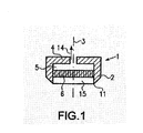
まず、図1を参照すると、切断装置の第1実施形態が示されている。この切断装置は、図1中、符号3で示された回転軸を有する回転対称な切断要素2を備えている。説明の簡略化のため、切断部のみが示されており、該切断装置1を操作および保持するために必要な他の構成要素については、示されていない。切断装置1は、例えば、ドリルチャック又はそれと類似するようなハウジング装置の中に収容することができる。この目的のため、該切断装置1はハウジング4を備えているが、説明の簡略化のため、ここでは詳細には示されていない。切断要素2は、全体としてコップ状に形成され、吸引装置14によって負圧とされるような自由空間5をハウジング4内に備えている。該切断装置1は、ハウジング4の反対側には切断エッジ11を有している。吸引リング13は、吸引リング13の内部に切断装置全体が目に吸引されうるような負圧を生じさせることにより、該切断装置を処置される目に固定することを可能とするものである。
Hereinafter, embodiments of the present invention will be described in detail with reference to the accompanying drawings.
First, referring to FIG. 1, a first embodiment of a cutting device is shown. This cutting device comprises a rotationally symmetric cutting element 2 having a rotation axis indicated by
該切断装置1を操作する際には、切断装置が回転軸3に対して回転するように運転される。切断エッジ11は、ボーマン膜上にある上皮に挿入される。吸引装置14の補助によって自由空間5内に負圧を生じさせることにより、上皮フラップ6は目から持ち上げられる。
When operating the
図2は、切断装置1の他の形態を示したものである。図1に示した態様とは異なり、ここでは、上皮フラップ6は負圧によって自由空間5に吸われるのではなく、支持面7上で凍結されることとなる。そのために、該切断装置1は、ペルチェ素子又は冷凍剤成分16を備えている。これは、支持面7に接触するようにして配置され、該自由空間5内に導かれる水又は他の液体の凝固点以下となるように、該支持面7を冷却しうるものである。
FIG. 2 shows another form of the
この第2実施形態に係る切断装置1は、図1に示された実施形態のものと同様にして使用される。該切断装置1は回転するように運転され、そして切断エッジ11は上皮に挿入される。切込みが十分に深くなれば、切り離された上皮フラップ6は、前記ペルチェ素子又は冷凍剤成分16によって前記支持面7上で凍結され、そして持ち上げられることとなる。
The
本発明に係る切断装置の更なる他の実施形態が、図3に示されている。この装置もまた、切断要素2を備えている。目に固定するための吸引リング13が、該切断要素2の外部領域に配置されている。振動素子12が、自由空間5の境となる支持面7上に配置されている。この支持面は、多くの孔を有するペルチェ素子16、又は孔の開けられた基板17とすることができる。該支持面7は、切断要素2の環状の窪み8の中において、径方向に移動可能な状態で配置されている。前記振動素子12は、一端が切断要素2上にあり、他端が支持面7上にあるように、配されている。この振動素子が作動した際には、支持面7の振動が起こり、これが図3おいて両矢印9で示されている。基板17の支持面7は、多孔質であるか又は複数の貫通孔を備え、上皮フラップ6のための自由空間5から空気が吸引装置14によって吸引され、該上皮フラップ6が支持面7に吸引されるように構成されている。
Yet another embodiment of a cutting device according to the present invention is shown in FIG. This device also comprises a cutting element 2. A
図3のような装置を使用する際、その手順は上で示されたものと同様であり、上皮フラップの緩めは、支持面7の振動運動によっても促進されることとなる。
When using a device such as that of FIG. 3, the procedure is similar to that shown above, and the loosening of the epithelial flap is also facilitated by the oscillatory movement of the
図4および図5は、該切断装置1を拡大した図を示している。軸方向の断面図が図4に示され、上方からみた概略図が図5に示されている。本実施形態の切断装置1は、更なる切断ユニット15によって補なわれている。ここで、該切断装置は、ワイヤ18を備えており、台車19に補助されたワイヤ18は、上皮フラップ6のためのガイドとなるように、切断エッジ11を通過するように案内される。この方法では、上皮フラップ6は、残存する上皮から安全に切り離される。該上皮は、上述したような、例えば負圧や冷凍による装置によって、保持されることとなる。
4 and 5 show enlarged views of the
或いは、上皮フラップ6は、ソフトコンタクトレンズへの接着によって保持される。該接着は、その都度、通常販売されているフィブリン接着剤、若しくは体内で自然に発生する他の物質であって、光学的にクリアーおよび/又は体温や涙液がコンタクトレンズに及ぼされる影響下において自己溶解性のあるような一成分と、上皮である他成分とにおいて達成される。これにより、一時的且つ可逆的に生じた上皮とフィブリン接着剤との融合体、および/又は接着性物質のみが、コンタクトレンズ上に包含されることとなる。そして、緩められた上皮表面にマーキングした後、完全な上皮の緩みおよびレンズへの粘着が行なわれる。コンタクトレンズは、上皮フラップの再度の取り付けおよび治癒の間、一時的に、レーザー処理された目の上に置かれる。
Alternatively, the
1 切断装置
2 切断要素
3 回転軸
4 ハウジング
5 自由空間
6 上皮フラップ
7 支持面
8 環状の窪み
9 両矢印
11 切断エッジ
12 振動要素
13 吸引リング
14 吸引装置
15 切断ユニット
16 ペルチェ素子又は冷凍剤成分
17 基板
18 ワイヤ
19 台車
DESCRIPTION OF
Claims (9)
切断エッジ(11)を備えた実質的に回転対称である切断要素(2)と、上皮フラップ(6)のための支持面(7)を備えた自由空間(5)と、さらに、該自由空間(5)と該上皮フラップ(6)との間に負圧を生じさせうる吸引装置により生じさせた負圧によって該上皮フラップ(6)を該支持面(7)に固定するための器具とを備えてなり、上皮フラップ(6)を固定するための前記器具が、冷却要素(16)を備えていることを特徴とする切断装置(1)。A cutting device (1) for excising the epithelial flap (6) from the eye,
A substantially rotationally symmetric cutting element (2) with a cutting edge (11), a free space (5) with a support surface (7) for the epithelial flap (6) , and the free space (5) and an instrument for fixing the epithelial flap (6) to the support surface (7) by a negative pressure generated by a suction device capable of generating a negative pressure between the epithelial flap (6). with Ri Na with the device for fixing the epithelial flap (6) is a cutting device characterized in that it comprises cooling elements (16) (1).
Applications Claiming Priority (2)
| Application Number | Priority Date | Filing Date | Title |
|---|---|---|---|
| DE10152152A DE10152152B4 (en) | 2001-10-25 | 2001-10-25 | cutter |
| PCT/EP2002/011926 WO2003034958A2 (en) | 2001-10-25 | 2002-10-25 | Cutting device |
Publications (2)
| Publication Number | Publication Date |
|---|---|
| JP2005528127A JP2005528127A (en) | 2005-09-22 |
| JP4291692B2 true JP4291692B2 (en) | 2009-07-08 |
Family
ID=7703348
Family Applications (1)
| Application Number | Title | Priority Date | Filing Date |
|---|---|---|---|
| JP2003537529A Expired - Fee Related JP4291692B2 (en) | 2001-10-25 | 2002-10-25 | Cutting device |
Country Status (7)
| Country | Link |
|---|---|
| US (1) | US20060190004A1 (en) |
| EP (2) | EP1832260A1 (en) |
| JP (1) | JP4291692B2 (en) |
| AT (1) | ATE364366T1 (en) |
| AU (1) | AU2002351785A1 (en) |
| DE (3) | DE20122067U1 (en) |
| WO (1) | WO2003034958A2 (en) |
Families Citing this family (9)
| Publication number | Priority date | Publication date | Assignee | Title |
|---|---|---|---|---|
| KR20050042819A (en) * | 2002-09-13 | 2005-05-10 | 오큘라 사이언시즈, 인크. | Devices and methods for improving vision |
| ES2286544T3 (en) * | 2004-08-12 | 2007-12-01 | GEBAUER GMBH & CO. KG | MICROQUERATOMO WITH SURGICAL KNIFE. |
| KR20080018988A (en) * | 2005-04-27 | 2008-02-29 | 티슈 엔지니어링 리프랙션 인코포레이티드 | Epithelial delaminating device(v) and blades useful in that device |
| WO2007090414A1 (en) * | 2006-02-07 | 2007-08-16 | Zyrus Beteiligungsgesellschaft Mbh & Co. Patente I Kg | Suction trephine |
| US7883520B2 (en) | 2006-04-10 | 2011-02-08 | Forsight Labs, Llc | Corneal epithelial pocket formation systems, components and methods |
| WO2008023193A2 (en) * | 2006-08-25 | 2008-02-28 | Jonathan James O'halloran | Device |
| WO2009140980A1 (en) * | 2008-05-21 | 2009-11-26 | Tutogen Medical Gmbh | Method and device for producing dermis |
| DE102011008604A1 (en) | 2011-01-14 | 2012-07-19 | Tutogen Medical Gmbh | Preparation of a graft of animal dermis with sodium sulfide solution |
| US9759263B1 (en) * | 2014-11-13 | 2017-09-12 | National Technology & Engineering Solutions Of Sandia, Llc | Rotation flexure with temperature controlled modal frequency |
Family Cites Families (24)
| Publication number | Priority date | Publication date | Assignee | Title |
|---|---|---|---|---|
| DE3409798C1 (en) * | 1984-03-16 | 1985-10-24 | Jörg Dr.med. 4630 Bochum Krumeich | Fixing arrangement for holding a corneal disk removed from the human eye |
| US6264648B1 (en) * | 1985-07-29 | 2001-07-24 | Bausch & Lomb Incorporated | Corneal curvature modification via internal ablation |
| US5215104A (en) * | 1988-08-16 | 1993-06-01 | Steinert Roger F | Method for corneal modification |
| DE3838253A1 (en) * | 1988-11-11 | 1990-05-23 | Krumeich Joerg H | Suction ring for operations on the human eye |
| US5133747A (en) * | 1990-03-16 | 1992-07-28 | Feaster Fred T | Epiphakic intraocular lens and process of implantation |
| US5269795A (en) * | 1991-07-03 | 1993-12-14 | Arnott Eric J | Trephine device for removing anterior epithelial cells from corneal surfaces |
| US5658303A (en) * | 1994-05-17 | 1997-08-19 | Koepnick; Russell G. | Universal automated keratectomy apparatus and method |
| US6551307B2 (en) * | 2001-03-23 | 2003-04-22 | Gholam A. Peyman | Vision correction using intrastromal pocket and flap |
| US5624456A (en) * | 1996-02-07 | 1997-04-29 | Hellenkamp; Johann F. | Automatic surgical device for cutting a cornea |
| EP0971659B1 (en) * | 1996-12-23 | 2003-11-12 | Instituto Barraquer De America | Microkeratome |
| US5830208A (en) * | 1997-01-31 | 1998-11-03 | Laserlite, Llc | Peltier cooled apparatus and methods for dermatological treatment |
| US6126668A (en) * | 1997-04-25 | 2000-10-03 | Innovative Optics, Inc. | Microkeratome |
| US5947987A (en) * | 1997-10-22 | 1999-09-07 | Medjet, Inc. | Tissue removal |
| EP1039863B1 (en) * | 1997-11-21 | 2005-06-08 | DYBBS, Alexander | Opthalmic surgical system |
| AUPQ167399A0 (en) * | 1999-07-15 | 1999-08-12 | Lions Eye Institute Of Western Australia Incorporated, The | Corneal cutting implement |
| DE50015215D1 (en) * | 1999-09-10 | 2008-07-31 | Haag Ag Streit | DEVICE FOR PHOTOABLATION OF THE CORNEA WITH A LASER BEAM |
| US6228113B1 (en) * | 2000-01-10 | 2001-05-08 | Board Of Supervisors Of Louisiana State University And Agricultural And Mechanical College | Intracorneal astigmatic onlay |
| US7977385B2 (en) * | 2000-03-02 | 2011-07-12 | Numoda Biotechnologies, Inc. | Agents for corneal or intrastromal administration to treat or prevent disorders of the eye |
| US6350272B1 (en) * | 2000-03-20 | 2002-02-26 | Glenn Kawesch | Method and apparatus for cutting an oblong corneal flap |
| DE10119477A1 (en) * | 2001-04-20 | 2002-10-24 | Gebauer Gmbh | LASEK eye surgery device for use in correction of sight defects has an improved cutter arrangement that ensures a cutter used to open up the cornea is correctly position perpendicular to the surface |
| US7087050B2 (en) * | 2001-06-28 | 2006-08-08 | Lahaye Leon C | Multi-function surgical instrument for facilitating ophthalmic laser surgery |
| US6656197B1 (en) * | 2001-06-28 | 2003-12-02 | Lahaye Leon C. | Multi-function surgical instrument for facilitating ophthalmic laser surgery |
| US7135028B2 (en) * | 2001-12-12 | 2006-11-14 | Nidek Co., Ltd. | Blade for corneal surgery and corneal surgical apparatus comprising the same |
| KR20050042819A (en) * | 2002-09-13 | 2005-05-10 | 오큘라 사이언시즈, 인크. | Devices and methods for improving vision |
-
2001
- 2001-10-25 DE DE20122067U patent/DE20122067U1/en not_active Expired - Lifetime
- 2001-10-25 DE DE10152152A patent/DE10152152B4/en not_active Expired - Fee Related
-
2002
- 2002-10-25 EP EP07011391A patent/EP1832260A1/en not_active Withdrawn
- 2002-10-25 WO PCT/EP2002/011926 patent/WO2003034958A2/en active IP Right Grant
- 2002-10-25 AU AU2002351785A patent/AU2002351785A1/en not_active Abandoned
- 2002-10-25 EP EP02787508A patent/EP1441678B1/en not_active Expired - Lifetime
- 2002-10-25 DE DE50210326T patent/DE50210326D1/en not_active Expired - Lifetime
- 2002-10-25 AT AT02787508T patent/ATE364366T1/en not_active IP Right Cessation
- 2002-10-25 JP JP2003537529A patent/JP4291692B2/en not_active Expired - Fee Related
- 2002-10-25 US US10/493,613 patent/US20060190004A1/en not_active Abandoned
Also Published As
| Publication number | Publication date |
|---|---|
| WO2003034958A3 (en) | 2004-02-19 |
| WO2003034958A2 (en) | 2003-05-01 |
| DE20122067U1 (en) | 2004-02-12 |
| EP1441678B1 (en) | 2007-06-13 |
| US20060190004A1 (en) | 2006-08-24 |
| DE50210326D1 (en) | 2007-07-26 |
| DE10152152B4 (en) | 2004-02-26 |
| DE10152152A1 (en) | 2003-05-15 |
| EP1441678A2 (en) | 2004-08-04 |
| ATE364366T1 (en) | 2007-07-15 |
| AU2002351785A1 (en) | 2003-05-06 |
| JP2005528127A (en) | 2005-09-22 |
| EP1832260A1 (en) | 2007-09-12 |
Similar Documents
| Publication | Publication Date | Title |
|---|---|---|
| US7156859B2 (en) | Device for separating the epithelium layer from the surface of the cornea of an eye | |
| US6458141B1 (en) | Method and apparatus for creating a flap in the cornea and incisions or shrinkage under the flap to correct vision disorders | |
| US6299611B1 (en) | System and method for modifying a live cornea via laser ablation and mechanical erosion | |
| JP3078564B2 (en) | Non-contact laser microscope corneal surgery device | |
| EP0997122B1 (en) | Apparatus for Improving LASIK flap adherence | |
| JP2018187402A (en) | Systems and methods for disruption of eye lens | |
| US20090069817A1 (en) | Intrastromal corneal modification | |
| JP2003180729A (en) | Apparatus for forming corneal flap | |
| JP2000501002A (en) | Corneal tissue resection instrument | |
| JPH03502537A (en) | Medical surgical device for biological tissues using laser beams | |
| JP4291692B2 (en) | Cutting device | |
| JP4187648B2 (en) | Device for separating the epithelial layer from the corneal surface of the eye | |
| JP2002541878A (en) | Keratotomy device | |
| JPH06174960A (en) | Laser beam transmission device | |
| JP2008508957A (en) | Device for separating the epithelial layer from the surface of the cornea | |
| US20040002722A1 (en) | Ultrasonic microkeratome | |
| JP2002119532A (en) | Blade assembly for microkeratome | |
| Albé et al. | Mechanical Microkeratomes | |
| KR200249321Y1 (en) | Suction Ring for LASEK | |
| Snyder et al. | Erbium: YAG laser for cataract extraction | |
| Kakaria et al. | Microkeratomes | |
| TARIB et al. | CAPSULOTOMY | |
| JPH06105863A (en) | Intraocular operation apparatus | |
| Frenz et al. | In vitro and in vivo retinal surgery with an Er: YAG laser | |
| Vajpayee et al. | Microkeratomes |
Legal Events
| Date | Code | Title | Description |
|---|---|---|---|
| A621 | Written request for application examination |
Free format text: JAPANESE INTERMEDIATE CODE: A621 Effective date: 20050705 |
|
| RD04 | Notification of resignation of power of attorney |
Free format text: JAPANESE INTERMEDIATE CODE: A7424 Effective date: 20080620 |
|
| A131 | Notification of reasons for refusal |
Free format text: JAPANESE INTERMEDIATE CODE: A131 Effective date: 20080711 |
|
| A601 | Written request for extension of time |
Free format text: JAPANESE INTERMEDIATE CODE: A601 Effective date: 20081010 |
|
| A602 | Written permission of extension of time |
Free format text: JAPANESE INTERMEDIATE CODE: A602 Effective date: 20081020 |
|
| A601 | Written request for extension of time |
Free format text: JAPANESE INTERMEDIATE CODE: A601 Effective date: 20081111 |
|
| A602 | Written permission of extension of time |
Free format text: JAPANESE INTERMEDIATE CODE: A602 Effective date: 20081118 |
|
| A521 | Request for written amendment filed |
Free format text: JAPANESE INTERMEDIATE CODE: A523 Effective date: 20081210 |
|
| TRDD | Decision of grant or rejection written | ||
| A01 | Written decision to grant a patent or to grant a registration (utility model) |
Free format text: JAPANESE INTERMEDIATE CODE: A01 Effective date: 20090313 |
|
| A01 | Written decision to grant a patent or to grant a registration (utility model) |
Free format text: JAPANESE INTERMEDIATE CODE: A01 |
|
| A61 | First payment of annual fees (during grant procedure) |
Free format text: JAPANESE INTERMEDIATE CODE: A61 Effective date: 20090403 |
|
| R150 | Certificate of patent or registration of utility model |
Free format text: JAPANESE INTERMEDIATE CODE: R150 |
|
| FPAY | Renewal fee payment (event date is renewal date of database) |
Free format text: PAYMENT UNTIL: 20120410 Year of fee payment: 3 |
|
| FPAY | Renewal fee payment (event date is renewal date of database) |
Free format text: PAYMENT UNTIL: 20130410 Year of fee payment: 4 |
|
| FPAY | Renewal fee payment (event date is renewal date of database) |
Free format text: PAYMENT UNTIL: 20140410 Year of fee payment: 5 |
|
| R250 | Receipt of annual fees |
Free format text: JAPANESE INTERMEDIATE CODE: R250 |
|
| R250 | Receipt of annual fees |
Free format text: JAPANESE INTERMEDIATE CODE: R250 |
|
| LAPS | Cancellation because of no payment of annual fees |