JP4289986B2 - Infrared bulb and heating device - Google Patents
Infrared bulb and heating device Download PDFInfo
- Publication number
- JP4289986B2 JP4289986B2 JP2003394050A JP2003394050A JP4289986B2 JP 4289986 B2 JP4289986 B2 JP 4289986B2 JP 2003394050 A JP2003394050 A JP 2003394050A JP 2003394050 A JP2003394050 A JP 2003394050A JP 4289986 B2 JP4289986 B2 JP 4289986B2
- Authority
- JP
- Japan
- Prior art keywords
- heating element
- light bulb
- infrared light
- holding member
- coil spring
- Prior art date
- Legal status (The legal status is an assumption and is not a legal conclusion. Google has not performed a legal analysis and makes no representation as to the accuracy of the status listed.)
- Expired - Fee Related
Links
Images


Landscapes
- Resistance Heating (AREA)
Description
本発明は、発熱体として炭素系物質を使用した赤外線電球及びその赤外線電球を用いた加熱装置に関するものであり、特に、発熱体と発熱体の端部を保持する保持部材との取り付け方に関する。 The present invention relates to an infrared light bulb using a carbon-based material as a heating element and a heating device using the infrared light bulb, and more particularly to a method of attaching the heating element and a holding member that holds an end of the heating element.
近年、炭素系物質を用いた赤外線電球が普及している。炭素系物質は赤外線放射率が78〜84%と高いため、発熱体として炭素系物質を用いることで赤外線電球の赤外線放射率も高くなる。また、炭素系物質は、温度上昇とともに抵抗値が低下する負の抵抗温度特性を有するため、点灯時の突入電流を低くできるという大きな特徴を有している。
国際公開第WO01/041507号パンフレットに開示されている、従来例の赤外線電球を図8及び図9を用いて説明する。図8は、従来例の赤外線電球の全体構造を示す斜視図である。なお、図8は赤外線電球の両端側部分を示しており、その中央部分は両端側部分を繋ぐよう連続した構造を有しているため省略している。
In recent years, infrared light bulbs using carbon-based materials have become widespread. Since the carbon-based material has a high infrared emissivity of 78 to 84%, the infrared emissivity of the infrared light bulb is increased by using the carbon-based material as the heating element. In addition, since the carbon-based material has a negative resistance-temperature characteristic in which the resistance value decreases as the temperature rises, the carbon-based material has a great feature that the inrush current during lighting can be reduced.
A conventional infrared light bulb disclosed in International Publication No. WO01 / 041507 will be described with reference to FIGS. FIG. 8 is a perspective view showing the overall structure of a conventional infrared light bulb. In addition, FIG. 8 has shown the both ends side part of the infrared lamp, and since the center part has the continuous structure which connects both end parts, it has abbreviate | omitted.
赤外線電球は、発熱体1と放熱ブロック2と内部リード線3をガラス管4内に挿入し、アルゴン等の不活性ガスを入れて、ガラス管4の端部を溶解融合して封止して形成されている。発熱体1は、黒鉛などの結晶化炭素の基材に窒素化合物の抵抗値調整物質、及びアモルファス炭素の混合物からなる炭素系物質で形成され、形状は板状である。放熱ブロック2は黒鉛等の導電性材料で形成されており、発熱体1の一端に電気的に接続されている。
In the infrared light bulb, the heating element 1, the
内部リード線3は、モリブデン線により形成され、内部リード線3の一端にコイルバネ部3aが形成されており、そのコイルバネ部3aに続いて弾性を有するスプリング部3bが形成されている。内部リード線3のコイルバネ部3aは放熱ブロック2の外周面に密着して巻回され電気的に接続されている。内部リード線3のスプリング部3bは、放熱ブロック2の外周面から所定間隔を有して配置されており、発熱体1の膨張による寸法変化をその伸び縮みにより打ち消し吸収できるよう構成されている。内部リード線3は、モリブデン箔5を介して外部リード線6に接続されている。
The
上記のように構成された赤外線電球において、両端の外部リード線6に電力を印加して、赤外線電球を点灯することにより、炭素系物質から形成された発熱体1はその抵抗により高温度になる。
放熱ブロック2自体の発熱は発熱体に比べて十分小さく無視できるものである。放熱ブロック2には発熱体1から熱が伝わってくるが、放熱ブロック2は表面積(輻射面積)が大きいため、その熱の一部は放熱ブロックの表面から発散する。そのため、放熱ブロック2と内部リード線3との接続部であるコイルバネ部3aの温度上昇を防ぐことができる。
発熱により発熱体1がその長手方向に膨張した場合でも、発熱体1とモリブデン箔5との間にスプリング部3bが設けられているため、発熱体1の膨張による寸法変化の影響はスプリング部3bの収縮により打ち消される。その結果、発熱体1に対して不要な曲げ力が働くことを防止することができる。このように、高温度で脆い状態の発熱体1に対して不要な曲げ力が加わることがないため、発熱体1は高温度になっても破損することがない。
In the infrared bulb configured as described above, by applying power to the external lead wires 6 at both ends and turning on the infrared bulb, the heating element 1 formed of the carbon-based material becomes high temperature due to its resistance. .
The heat generation of the
Even when the heating element 1 expands in the longitudinal direction due to heat generation, since the
図9を用いて、発熱体1と放熱ブロック2との嵌合方法を説明する。図9は、従来例の赤外線電球の発熱体1と放熱ブロック2との嵌合の構造を示す部分拡大斜視図である。図9に示すように、赤外線電球の製造時において、発熱体1の端部近傍に形成された溝92を含む発熱体1の先端部分には、液状の炭素系有機物質を主成分とする接着剤91が十分に塗布される。一般的炭素系接着剤は、カーボンブラックを熱硬化性樹脂(ポリエステル樹脂やポリイミド樹脂が望ましい)にブレンドし、ペースト状にしたものである。接着剤91が塗布された発熱体1は、放熱ブロック2のスリット93に挿入され、密着される。発熱体1が放熱ブロック2に密着嵌合された後、乾燥、加温(焼成)により接着剤91の炭素系物質を主成分とする導電性の高い焼結体が形成される。この結果、発熱体1と放熱ブロック2は導電性の高い接着剤91の焼結体により接続される。
The fitting method of the heat generating body 1 and the
発熱体と放熱ブロック間を炭素系接着剤で接着する構成にすることで、接合部の強度が大きくなる。接着剤が発熱体及び放熱ブロックと同じ炭素系物質であり、それぞれの熱膨張係数がほぼ等しいため、加熱のオン・オフによる温度サイクルに強い、信頼性の高い赤外線電球を提供できる。
発熱体1に溝92を形成することにより、発熱体1と放熱ブロック2との接触面積が増加し、接触抵抗を小さくすることができる。また、炭素系有機物質の接着剤91は黒鉛の放熱ブロック2に特に固着しやすいため、溝92に接着剤91が入り込み、発熱体1と放熱ブロック2との間は凹凸面の接合になり、接合強度は飛躍的に向上している。
By adopting a configuration in which the heating element and the heat dissipation block are bonded with a carbon-based adhesive, the strength of the joint portion is increased. Since the adhesive is the same carbon-based material as the heating element and the heat dissipation block, and their respective thermal expansion coefficients are substantially equal, it is possible to provide a highly reliable infrared bulb that is resistant to temperature cycles caused by heating on and off.
By forming the
特許文献1に記載された従来例の赤外線電球において、接着剤を用いて発熱体と放熱ブロックを接合する場合、接着剤が乾燥するのに時間がかかった。乾燥時に接着剤の割れ等が発生する場合があった。
接着剤を塗布した発熱体1を放熱ブロックに挿入しても接着剤の巻き込みが十分に起こらず、スリット内に均一に接着剤が塗布できない場合があった。その結果、発熱体1と放熱ブロック2との電気的接合面積が低下し、接触抵抗が増大することとなる。最悪の場合にはこの接合部の発熱により、放熱ブロック2が異常高温となり、放熱ブロック2の外周部に巻回されたコイルバネ部3aが溶断してしまうという問題があった。
接着剤の塗布から硬化の為の熱処理までの間に、大きな衝撃や取り扱い上の不注意により、発熱体1と放熱ブロック2との位置関係がずれてしまうおそれもあった。発熱体1と放熱ブロック2との位置関係がずれると、発熱部の抵抗値が変わり、赤外線電球のワット数も変わってしまう。
In the conventional infrared light bulb described in Patent Document 1, when the heating element and the heat dissipation block are bonded using an adhesive, it takes time for the adhesive to dry. In some cases, the adhesive cracked during drying.
Even when the heating element 1 to which the adhesive has been applied is inserted into the heat dissipation block, the adhesive does not sufficiently entrain, and the adhesive may not be uniformly applied in the slit. As a result, the electrical junction area between the heating element 1 and the
Between the application of the adhesive and the heat treatment for curing, the positional relationship between the heating element 1 and the
本発明は、上記の問題を解決するためになされるものであり、発熱体とリード線の接続部の温度上昇を低く抑えることができ、発熱体と放熱ブロック(保持部材)との取付部の信頼性を飛躍的に向上することができ、従来の方法と較べてはるかに短い時間で発熱体とリード線とを接続することができる赤外線電球、及びその赤外線電球を用いた加熱装置を提供することを目的とする。 The present invention is made in order to solve the above-described problem, and can suppress a temperature rise in the connecting portion between the heating element and the lead wire, and the mounting portion between the heating element and the heat radiation block (holding member) can be suppressed. Provided are an infrared bulb that can dramatically improve reliability and can connect a heating element and a lead wire in a much shorter time than a conventional method, and a heating device using the infrared bulb. For the purpose.
上記課題を解決するため、本発明は下記の構成を有する。請求項1に記載の発明は、長手方向に延びる少なくとも1本の発熱体の両端に、それぞれリード線の一方の端部が直接又は他の導電体を介して電気的に接続され、前記リード線の他の端部がガラス管外に導出されるように、前記発熱体及び前記リード線がガラス管内に封入された赤外線電球であって、前記発熱体の端部を保持する少なくとも1個の保持部材と、バネ材とを有し、前記保持部材は、第1の部材と、第2の部材とを有し、前記第1の部材と前記第2の部材とは、前記発熱体の長手方向の延長線上において互いの接点を有し、且つ前記発熱体の端部を挟持し、前記バネ材は、前記第1の部材と前記第2の部材とを挟み込んで、前記第1の部材と前記第2の部材とが前記接点を支点として前記発熱体の端部を挟み付ける方向にモーメントを生じるように、前記第1の部材と前記第2の部材に応力を加えることを特徴とする赤外線電球である。 In order to solve the above problems, the present invention has the following configuration. According to the first aspect of the present invention, one end of a lead wire is electrically connected to both ends of at least one heating element extending in the longitudinal direction, either directly or via another conductor, and the lead wire An infrared bulb in which the heating element and the lead wire are enclosed in a glass tube so that the other end portion is led out of the glass tube, and at least one holding for holding the end portion of the heating element A holding member; a first member; and a second member, wherein the first member and the second member are longitudinal directions of the heating element. On the extended line, and sandwiching the end of the heating element, the spring material sandwiches the first member and the second member, the first member and the The second member is in the direction of sandwiching the end of the heating element with the contact as a fulcrum. To produce the door, an infrared bulb, characterized in that stress the said first member and said second member.
支点を定めることなくバネ材が第1の部材と第2の部材とを締め付ける構成では、バネ材の締め付けトルクが第1の部材、第2の部材及び発熱体に生じさせる応力の大きさ及び方向は一定しない。本発明においては、バネ材によって接点を支点とする一定のモーメントを発生させて、第1の部材及び第2の部材が発熱体の端部を確実に一定の力で発熱体の食い込み方向に挟持する。接着剤を用いない故に、接着剤を用いて発熱体と保持部材を接合した従来例の赤外線電球における種々の問題が発生しない。即ち、本発明の赤外線電球は、接着剤が接合面に均一に広がっていないので接合部が高温になるという問題、接着剤が硬化する前に発熱体が保持部材からずれるという問題、乾燥時に接着剤が割れるという問題が発生しない。接着剤を硬化させる工程が不要である故に少ない製造工数で且つ高い歩留まりで赤外線電球を製造できる。
本発明は、発熱体とリード線の接続部の温度上昇を低く抑えることができ、発熱体と保持部材との取付部の信頼性を飛躍的に向上することができ、短時間で発熱体とリード線とを接続することができる赤外線電球を実現出来るという作用を有する。
In the configuration in which the spring material fastens the first member and the second member without defining a fulcrum, the magnitude and direction of the stress generated by the tightening torque of the spring material on the first member, the second member, and the heating element Is not constant. In the present invention, the spring member generates a constant moment with the contact as a fulcrum, and the first member and the second member securely hold the end of the heating element with a constant force in the direction in which the heating element bites. To do. Since no adhesive is used, various problems do not occur in the conventional infrared light bulb in which the heating element and the holding member are joined using the adhesive. That is, the infrared light bulb of the present invention has a problem that the adhesive does not spread evenly on the joint surface, so that the joint becomes high temperature, a problem that the heating element deviates from the holding member before the adhesive is cured, and an adhesive when dried. The problem that the agent breaks does not occur. Since the step of curing the adhesive is unnecessary, an infrared light bulb can be manufactured with a small number of manufacturing steps and a high yield.
The present invention can suppress a rise in the temperature of the connecting portion between the heating element and the lead wire, and can greatly improve the reliability of the mounting portion between the heating element and the holding member. It has the effect | action that the infrared light bulb which can connect with a lead wire is realizable.
請求項2に記載の発明は、前記バネ材はコイルバネであって、前記第1の部材と前記第2の部材とを前記コイルバネを半径方向に押し広げながらその中に挿入する構成により、前記バネ材は、前記第1の部材と前記第2の部材とが前記接点を支点として前記発熱体の端部を挟み付ける方向にモーメントを生じるように、前記第1の部材と前記第2の部材に応力を加えることを特徴とする請求項1に記載の赤外線電球である。本発明は、コイルバネと第1の部材と第2の部材と発熱体とを簡単な方法で組立可能な赤外線電球を実現する。 According to a second aspect of the present invention, the spring material is a coil spring, and the first member and the second member are inserted into the coil spring while expanding the coil spring in a radial direction. The material is applied to the first member and the second member so that the first member and the second member generate a moment in a direction in which the end of the heating element is sandwiched with the contact as a fulcrum. 2. The infrared light bulb according to claim 1, wherein stress is applied. The present invention realizes an infrared light bulb in which a coil spring, a first member, a second member, and a heating element can be assembled by a simple method.
請求項3に記載の発明は、前記バネ材は筒状部材の内面に取り付けられた板バネであって、前記第1の部材と前記第2の部材とを、前記板バネを前記筒状部材の内面に押し当てながら前記筒状部材の中に挿入する構成により、前記バネ材は、前記第1の部材と前記第2の部材とが前記接点を支点として前記発熱体の端部を挟み付ける方向にモーメントを生じるように、前記第1の部材と前記第2の部材に応力を加えることを特徴とする請求項1に記載の赤外線電球である。本発明は、板バネと第1の部材と第2の部材と発熱体とを簡単な方法で組立可能な赤外線電球を実現する。 According to a third aspect of the present invention, the spring material is a leaf spring attached to an inner surface of a cylindrical member, and the first member and the second member are replaced with the leaf spring. The spring member is sandwiched between the first member and the second member with the contact point as a fulcrum, and is inserted into the cylindrical member while being pressed against the inner surface of the spring member. The infrared light bulb according to claim 1, wherein stress is applied to the first member and the second member so as to generate a moment in a direction. The present invention realizes an infrared light bulb in which a leaf spring, a first member, a second member, and a heating element can be assembled by a simple method.
請求項4に記載の発明は、長手方向に延びる少なくとも1本の発熱体の両端に、それぞれリード線の一方の端部が直接又は他の導電体を介して電気的に接続され、前記リード線の他の端部がガラス管外に導出されるように、前記発熱体及び前記リード線がガラス管内に封入された赤外線電球であって、前記発熱体の端部を保持する少なくとも1個の保持部材を有し、前記保持部材は、全体で連続する1つの面を形成する第1の面、第2の面、第3の面、第4の面及び第5の面を有し、前記第1の面と前記第5の面とは互いに対向してその間に前記発熱体の端部を挟み、前記第1の面に続く前記第2の面と前記第5の面に続く前記第4の面とは前記発熱体と接しておらず、前記発熱体の長手方向の延長線上にある前記第3の面は前記第2の面と前記第4の面とを結合し、前記第1の面と前記第5の面との間隔は前記発熱体の厚さより狭く形成されており、それを押し広げて前記発熱体の端部を挿入することにより、前記保持部材は、前記第1の面と前記第5の面とが前記第3の面を支点として前記発熱体の端部を挟み付けるように、応力を生じる構成としたことを特徴とする赤外線電球である。 According to the fourth aspect of the present invention, one end of a lead wire is electrically connected to both ends of at least one heating element extending in the longitudinal direction, respectively, directly or via another conductor, and the lead wire An infrared bulb in which the heating element and the lead wire are enclosed in a glass tube so that the other end portion is led out of the glass tube, and at least one holding for holding the end portion of the heating element The holding member has a first surface, a second surface, a third surface, a fourth surface, and a fifth surface forming one continuous surface as a whole; The first surface and the fifth surface face each other and sandwich the end of the heating element therebetween, and the second surface following the first surface and the fourth surface following the fifth surface The surface is not in contact with the heating element, and the third surface on the longitudinal extension of the heating element is the second surface. The fourth surface is joined, and the distance between the first surface and the fifth surface is narrower than the thickness of the heating element, and the end of the heating element is inserted by expanding it. Thus, the holding member is configured to generate stress so that the first surface and the fifth surface sandwich the end portion of the heating element with the third surface as a fulcrum. It is an infrared light bulb that is characterized.
本発明においては、第1の面と第5の面とに、それらの間隔を押し広げて発熱体を挟み込むことによって第3の面を支点とする一定のモーメントを発生させて、第1の面及び第5の面が発熱体の端部を確実に一定の力で挟持する。第2の面と第4の面とは発熱体と接していない故に、発熱体と第2の面又は第4の面との間に接触部分が発生して第1の面又は第5の面と発熱体との間に隙間が出来てしまう(第1の面又は第5の面が発熱体を保持する役割を果たさない)という恐れはない。接着剤を用いない故に、接着剤を用いて発熱体と保持部材を接合した従来例の赤外線電球における上記の種々の問題が発生しない。接着剤を硬化させる工程が不要である故に少ない製造工数で且つ高い歩留まりで赤外線電球を製造できる。
本発明は、発熱体とリード線の接続部の温度上昇を低く抑えることができ、発熱体と保持部材との取付部の信頼性を飛躍的に向上することができ、短時間で発熱体とリード線とを接続することができる赤外線電球を実現出来るという作用を有する。
In the present invention, a constant moment with the third surface as a fulcrum is generated by pushing the gap between the first surface and the fifth surface so as to sandwich the heating element, thereby generating the first surface. The fifth surface securely holds the end of the heating element with a constant force. Since the second surface and the fourth surface are not in contact with the heating element, a contact portion is generated between the heating element and the second surface or the fourth surface, so that the first surface or the fifth surface is formed. There is no fear that a gap is formed between the heating element and the heating element (the first surface or the fifth surface does not play a role of holding the heating element). Since no adhesive is used, the above-described various problems do not occur in the conventional infrared light bulb in which the heating element and the holding member are joined using the adhesive. Since the step of curing the adhesive is unnecessary, an infrared light bulb can be manufactured with a small number of manufacturing steps and a high yield.
The present invention can suppress a rise in the temperature of the connecting portion between the heating element and the lead wire, and can greatly improve the reliability of the mounting portion between the heating element and the holding member. It has the effect | action that the infrared light bulb which can connect with a lead wire is realizable.
請求項5に記載の発明は、コイルバネを更に有し、前記保持部材を前記コイルバネを半径方向に押し広げながらその中に挿入する構成により、前記コイルバネは、前記第1の面と前記第5の面とが前記第3の面を支点として前記発熱体の端部を挟み付ける方向にモーメントを生じるように、前記保持部材に応力を加えることを特徴とする請求項4に記載の赤外線電球である。本発明は、コイルバネと保持部材と発熱体とを簡単な方法で組立可能な赤外線電球を実現する。 According to a fifth aspect of the present invention, the coil spring further includes a coil spring, and the holding member is inserted into the coil spring while expanding the coil spring in the radial direction. The coil spring includes the first surface and the fifth surface. 5. The infrared light bulb according to claim 4, wherein a stress is applied to the holding member so that a surface generates a moment in a direction of sandwiching an end portion of the heating element with the third surface as a fulcrum. . The present invention realizes an infrared light bulb in which a coil spring, a holding member, and a heating element can be assembled by a simple method.
請求項6に記載の発明は、前記保持部材は、外周に角部を有し、前記角部によってコイルバネが回転しないように保持されることを特徴とする請求項2又は請求項5に記載の赤外線電球である。この構成により、コイルバネが保持部材から外れるという事故を防止できる。 According to a sixth aspect of the present invention, the holding member has a corner portion on an outer periphery, and is held by the corner portion so that a coil spring does not rotate. It is an infrared bulb. With this configuration, it is possible to prevent an accident that the coil spring is detached from the holding member.
請求項7に記載の発明は、前記保持部材が前記発熱体を挟持する部分における外径が、前記保持部材の支点における外径と同一又はそれ以下であることを特徴とする請求項6に記載の赤外線電球である。コイルバネが保持部材を締め付ける故に、その締め付けトルクが小さくなる方向にコイルバネを動かす力が絶えず加わる。本発明においては、コイルバネを発熱体の中心に向う方向に動かす力が働く。一方、発熱体をガラス管の中で保持するため、コイルバネにはガラス管の端部に向う(上記の力と反対方向の)力も働く。コイルバネを2方向に引っ張る力はバランスする故に、コイルバネが保持部材から外れるという事故を確実に防止できる。 The invention described in claim 7 is characterized in that the outer diameter of the portion where the holding member holds the heating element is equal to or less than the outer diameter of the fulcrum of the holding member. Infrared light bulb. Since the coil spring tightens the holding member, a force for moving the coil spring is constantly applied in a direction in which the tightening torque is reduced. In this invention, the force which moves a coil spring in the direction which goes to the center of a heat generating body acts. On the other hand, in order to hold the heating element in the glass tube, a force (opposite to the above force) acting on the end of the glass tube also acts on the coil spring. Since the force that pulls the coil spring in two directions is balanced, it is possible to reliably prevent an accident that the coil spring is detached from the holding member.
請求項8に記載の発明は、前記保持部材が前記発熱体と密着する部分が、前記発熱体の中心に近い側の前記保持部材の先端の近傍であって、且つその先端より前記発熱体の中心から遠い位置にあることを特徴とする請求項1から請求項5のいずれかの請求項に記載の赤外線電球である。保持部材の先端の近傍で発熱体を保持することにより、支点から保持点までの距離が最も長くなる故に、モーメントが最大になる。本発明は、発熱体を強い力で挟んで保持する赤外線電球を実現する。保持部材の先端に強い応力がかかると、先端部が欠け易いという問題が発生する。本発明においては、保持点を先端より少し内側(発熱体の中心から遠い位置)に位置させることにより、保持部材が欠けるという事故を防止する。 According to an eighth aspect of the present invention, the portion where the holding member is in close contact with the heating element is in the vicinity of the tip of the holding member on the side close to the center of the heating element, and from the tip of the heating element. The infrared light bulb according to any one of claims 1 to 5, wherein the infrared light bulb is located far from the center. By holding the heating element near the tip of the holding member, the distance from the fulcrum to the holding point is the longest, so the moment is maximized. The present invention realizes an infrared light bulb that holds and holds a heating element with a strong force. When a strong stress is applied to the tip of the holding member, there arises a problem that the tip is easily chipped. In the present invention, the holding point is positioned slightly inside the tip (a position far from the center of the heating element), thereby preventing an accident that the holding member is missing.
請求項9に記載の発明は、前記発熱体の中心に近い側の前記保持部材の先端が面取りされていることを特徴とする請求項8に記載の赤外線電球である。本発明においては、保持部材の先端が欠けるという事故を防止する。 The invention according to claim 9 is the infrared light bulb according to claim 8, wherein a tip of the holding member on a side close to a center of the heating element is chamfered. In the present invention, an accident that the tip of the holding member is missing is prevented.
請求項10に記載の発明は、前記保持部材又は前記発熱体に凸部を設け、前記凸部で前記保持部材と前記発熱体とが密着することを特徴とする請求項1から請求項9のいずれかの請求項に記載の赤外線電球である。本発明の赤外線電球においては、保持部材が発熱体を挟み込む保持点が凸部に定まり、且つバネ材の応力が凸部に集中する。本発明は、発熱体を凸部で確実に保持する赤外線電球を実現する。 The invention according to claim 10 is characterized in that a convex portion is provided on the holding member or the heating element, and the holding member and the heating element are in close contact with each other at the convex portion. An infrared light bulb according to any claim. In the infrared light bulb of the present invention, the holding point at which the holding member sandwiches the heating element is determined on the convex portion, and the stress of the spring material is concentrated on the convex portion. The present invention realizes an infrared light bulb that securely holds a heating element by a convex portion.
請求項11に記載の発明は、前記発熱体又は前記保持部材において、前記凸部に対応する位置に前記凸部の突出量より浅い深さを有する凹部を設け、前記凸部で前記保持部材と前記発熱体とが密着することを特徴とする請求項10に記載の赤外線電球である。本発明は、発熱体を凸部で確実に保持する赤外線電球を実現する。例えば保持部材の凸部が発熱体の凹部にはまり込む(又は発熱体の凸部が保持部材の凹部にはまり込む)故に、保持部材と発熱体とが互いにずれる恐れがない。本発明は、発熱体と保持部材との取付部の信頼性を更に向上する赤外線電球を実現する。 According to an eleventh aspect of the present invention, in the heating element or the holding member, a concave portion having a depth shallower than a protruding amount of the convex portion is provided at a position corresponding to the convex portion, and the convex portion includes the holding member and the holding member. The infrared light bulb according to claim 10, wherein the heating element is in close contact with the infrared light bulb. The present invention realizes an infrared light bulb that securely holds a heating element by a convex portion. For example, since the convex part of the holding member fits into the concave part of the heating element (or the convex part of the heating element fits into the concave part of the holding member), there is no possibility that the holding member and the heating element are shifted from each other. The present invention realizes an infrared light bulb that further improves the reliability of the attachment portion between the heating element and the holding member.
請求項12に記載の発明は、前記保持部材と前記発熱体が密着する部分において、両面または少なくとも一方が最大面粗さRy10μm以上の粗さを有することを特徴とする請求項1から請求項9のいずれかの請求項に記載の赤外線電球である。面の粗さに起因して保持部材と発熱体との間に所定以上の摩擦力が働く故に、両者が互いにずれる恐れがない。本発明は、発熱体と保持部材との取付部の信頼性を更に向上する赤外線電球を実現する。 According to a twelfth aspect of the present invention, in the portion where the holding member and the heating element are in close contact with each other, both surfaces or at least one has a roughness of a maximum surface roughness Ry of 10 μm or more. An infrared bulb according to any one of the claims. Due to the roughness of the surface, a frictional force of a predetermined level or more acts between the holding member and the heating element, so that there is no possibility that they are shifted from each other. The present invention realizes an infrared light bulb that further improves the reliability of the attachment portion between the heating element and the holding member.
請求項13に記載の発明は、前記保持部材と前記発熱体との間に繊維状のカーボンシートを挟む構成を有することを特徴とする請求項1から請求項12のいずれかの請求項に記載の赤外線電球である。この構成により、更に発熱体と保持部材とがずれにくくなり、且つ両者の間の接触抵抗値が小さくなる。 The invention according to claim 13 has a configuration in which a fibrous carbon sheet is sandwiched between the holding member and the heating element, according to any one of claims 1 to 12. Infrared light bulb. With this configuration, the heating element and the holding member are not easily displaced, and the contact resistance value between the two is reduced.
請求項14に記載の発明は、前記コイルバネが、その一端がガラス管の端部に結合されており、前記ガラス管内で、前記発熱体及び前記保持部材を保持することを特徴とする請求項2又は請求項5に記載の赤外線電球である。本発明においては、コイルバネが、保持部材が発熱体を保持する力を発生すると共に、ガラス管内で保持部材及び発熱体を保持する役割を果たす。本発明は、保持部材と発熱体との取付部が高い信頼性を有する簡単な構成の赤外線電球を実現する。
The invention according to claim 14 is characterized in that one end of the coil spring is coupled to an end of a glass tube, and the heating element and the holding member are held in the glass tube. Alternatively, the infrared light bulb according to
請求項15に記載の発明は、前記コイルバネが前記リード線を兼ねることを特徴とする請求項2又は請求項5に記載の赤外線電球である。本発明においては、コイルバネが更にリード線の役割も果たす。
The invention according to claim 15 is the infrared light bulb according to
請求項16に記載の発明は、請求項1から請求項15のいずれかの請求項に記載の赤外線電球を有する加熱装置である。本発明は、上記の作用を有する加熱装置を実現する。 A sixteenth aspect of the present invention is a heating apparatus having the infrared light bulb according to any one of the first to fifteenth aspects. This invention implement | achieves the heating apparatus which has said effect | action.
本発明は、発熱体とリード線の接続部の温度上昇を低く抑えることができ、発熱体と放熱ブロック(保持部材)との取付部の信頼性を飛躍的に向上することができ、短時間で発熱体とリード線とを接続することができる赤外線電球、及びその赤外線電球を用いた加熱装置を実現できるという有利な効果が得られる。 The present invention can suppress a rise in temperature at the connecting portion between the heating element and the lead wire, and can greatly improve the reliability of the mounting portion between the heating element and the heat dissipation block (holding member), for a short time. Thus, an advantageous effect that an infrared light bulb that can connect the heating element and the lead wire and a heating device using the infrared light bulb can be realized.
以下本発明の実施をするための最良の形態を具体的に示した実施の形態について、図面とともに記載する。 DESCRIPTION OF THE PREFERRED EMBODIMENTS Embodiments that specifically show the best mode for carrying out the present invention will be described below with reference to the drawings.
《実施の形態1》
図1〜3及び図8を用いて、本発明の実施の形態1の赤外線電球について説明する。図8は、本発明の赤外線電球の全体の構成を示す斜視図である。図8は、赤外線電球の両端側部分を示しており、その中央部分は両端側部分を繋ぐよう連続した構造を有しているため省略している。
本発明の赤外線電球は、発熱体1、放熱ブロック2、内部リード線3、コイルバネ部3a、スプリング部3b、ガラス管4、モリブデン箔5、外部リード線6を有する。本発明の赤外線電球において、従来例と同一部には同一の符号を付している。
Embodiment 1
The infrared light bulb according to the first embodiment of the present invention will be described with reference to FIGS. FIG. 8 is a perspective view showing the overall configuration of the infrared light bulb of the present invention. FIG. 8 shows both end portions of the infrared light bulb, and a central portion thereof is omitted because it has a continuous structure connecting the both end portions.
The infrared light bulb of the present invention has a heating element 1, a
発熱体1は、黒鉛などの結晶化炭素の基材に窒素化合物の抵抗値調整物質、及びアモルファス炭素の混合物からなる炭素系物質で形成されている。この発熱体1の形状は板状であり、例えば、幅6mm、厚み0.5mm、長さ300mmに形成されている。
放熱ブロック(保持部材)2は導電性材料で形成されており、発熱体1の一端に電気的に接続されている。
The heating element 1 is formed of a carbon-based material made of a mixture of a resistance adjusting substance of a nitrogen compound and amorphous carbon on a crystallized carbon substrate such as graphite. The heating element 1 has a plate shape, for example, a width of 6 mm, a thickness of 0.5 mm, and a length of 300 mm.
The heat dissipating block (holding member) 2 is formed of a conductive material and is electrically connected to one end of the heating element 1.
内部リード線3は、その一端にコイルバネ部3aが形成されており、そのコイルバネ部3aに続いて弾性を有するスプリング部3bが形成されている。図8に示すように、内部リード線3のコイルバネ部3aが放熱ブロック2の外周面に密着して巻回され電気的に接続されている。
内部リード線3のスプリング部3bは、放熱ブロック2の外周面から所定の間隔を有して配置されており、発熱体1の膨張による寸法変化を吸収できるように構成されている。実施の形態1において、内部リード線3はモリブデン線により形成する。
内部リード線3の他端は、ガラス管4の端部に結合されており、発熱体1は、両端を放熱ブロック2と内部リード線3とで保持される。
The
The
The other end of the
ガラス管4は石英ガラス(例えば、GE社製214又はダウコーニング社製バイコールガラス(品番 #7190))の非晶質ガラスである。ガラス管4は、発熱体1と放熱ブロック2と内部リード線3とを封入し、アルゴン等の不活性ガスを入れて、ガラス管4の端部を溶解融合して封止している。
封止部において、内部リード線3の端には、モリブデン箔5が溶接して接続されている。モリブデン箔5には外部リード線6であるモリブデン線がスポット溶接法により接合されている。
外部リード線6に電力を印加すると、発熱体1に電流が流れ、その電流に対する発熱体の抵抗により熱が生じる。このとき、発熱体からは赤外線が輻射される。赤外線電球は、発熱体1の発熱温度が1500℃以下で定常状態になるように設計されている。
The glass tube 4 is an amorphous glass of quartz glass (for example, GE 214 or Dow Corning Vycor glass (product number # 7190)). The glass tube 4 encloses the heating element 1, the
In the sealing portion, the
When electric power is applied to the external lead wire 6, a current flows through the heating element 1, and heat is generated by the resistance of the heating element to the current. At this time, infrared rays are radiated from the heating element. The infrared light bulb is designed such that the heat generating temperature of the heat generating element 1 is in a steady state at 1500 ° C. or lower.
本発明の赤外線電球が、従来例の赤外線電球と異なる点は、発熱体1と放熱ブロック2との嵌合方法である。図1〜図3に本発明の実施の形態1の赤外線電球における発熱体1と放熱ブロック2との嵌合方法を示す。
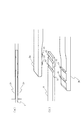
図1は、本発明の実施の形態1の赤外線電球における放熱ブロックの構造を示す正面図(a)及び右側面図(b)である。図1は、赤外線電球の一方の端の構造の一部を示したものであり、赤外線電球の他方の端も同様の構造となっている。本発明の放熱ブロック2は、導電性に優れた炭素系物質で形成されている。本発明の放熱ブロックは、第1の部材2aと第2の部材2bとで構成される。
The infrared light bulb of the present invention is different from the conventional infrared light bulb in the method of fitting the heating element 1 and the
1A is a front view and FIG. 1B is a right side view showing the structure of a heat dissipation block in the infrared light bulb according to the first embodiment of the present invention. FIG. 1 shows a part of the structure of one end of an infrared light bulb, and the other end of the infrared light bulb has a similar structure. The
第1の部材2aと第2の部材2bとは、図3に示す凸部31の位置が互いに異なることを除いて、同一形状である。図2は、放熱ブロックの第1の部材2a(及び第2の部材2b)の3面図(正面図、底面図、右側面図)である。図2の右側面図において、第1の部材2a(及び第2の部材2b)の上面21fは直線状であり、下面は、右から、上面21fと平行な面21e、左上がりの斜面21c、及び上面21fと平行な面21dからなる。上面21fと下面21dとの間隔と発熱体1の厚さの1/2とを加えた間隔は、上面21fと下面21eとの間隔よりわずかに狭い。斜面21cの右端に、凹部21aと凸部21bとが設けられている。凸部21bの高さは凹部21aの深さよりわずかに小さい。
The
第1の部材2aと第2の部材2bとは、第1の部材2aの凹部21a及び凸部21bが第2の部材2bの凸部21b及び凹部21aとそれぞれ向かい合って嵌合する様にし、2つの部材2a及び2bの面21dの間に発熱体1を挟み込んだ状態でコイルバネ3aによって固定される。第1の部材2a及び第2の部材2bの下面21dの間に発熱体1を挟み込んだ部分全体の外径は、第1の部材2a及び第2の部材2bの面21eを向い合わせた部分全体の外径より小さい。図2の右側面図において、面21eの接点がシーソーの支点のようになる。即ち、その支点の左右において(少なくとも左側において)両者の間にわずかの隙間を持つ。第1の部材2aと第2の部材2bとは、その接点(支点)の左側に位置する面21dにおいて発熱体1を挟み込む。コイルバネ3aが、凸部21bと凹部21aとが嵌合する所より左側を締め付けることにより(実施の形態1では、斜面21cを含む部分の外周を締め付ける。)、第1の部材2aと第2の部材2bとは、面21eの接点を支点として、発熱体3の端部を挟み付ける方向にモーメントを生じ、面21dにおいて発熱体3を挟持する。
The
放熱ブロック2に巻回した内部リード線3のコイルバネ部3aの巻き線の装着前の内径は、放熱ブロック(第1の部材2aと第2の部材2b)の外径より小さめにしてある。第1の部材2aと第2の部材2bとは、コイルバネ部3aを半径方向に押し広げながら、且つコイルバネ3aのバネの長手方向に沿って放熱ブロック(第1の部材2aと第2の部材2b)を回転させながら、その中に挿入される。コイルバネ3aが凸部21b及び凹部21aから左側(発熱体に近い側)に位置させるように組み立てる。実施の形態においては、コイルバネ3aは、放熱ブロックの長手方向において、斜面21cとほぼ同じ位置である。コイルバネ3aは、放熱ブロックの長手方向において、面21dとほぼ同じ位置であっても良い。
この構成により、コイルバネ部3aは、第1の部材2aと第2の部材2bとが接点を支点として発熱体1の端部を挟み付ける方向にモーメントを生じるように、第1の部材2aと第2の部材2bに応力を加える。
The inner diameter of the
With this configuration, the
第1の部材2aと第2の部材2bとで構成される放熱ブロック2において、発熱体1を挟持する部分における外径、及びコイルバネ3aが放熱ブロックを締め付ける部分における外径は、放熱ブロック2の支点(第1の部材2aの面21eと第2の部材2bの面21eとの接点)における外径と同一又はそれ以下とする(好ましくは実施の形態の様にわずかに小さい。)。これにより赤外線電球を組み立てた後、コイルバネ3aが放熱ブロックからはずれ落ちることを防止できる。
第1の部材2aと第2の部材2bはそれぞれの凹部21a及び凸部21bを有し、それらが互いに嵌合することによって、第1の部材と第2の部材との位置が固定される。
放熱ブロック2は外周に角部22を有し、角部22によってコイルバネ部3aが回転しないように保持される。内部リード線3方向からコイルバネ部3aに引っ張り力を加えた場合においても、コイルバネ部3aが抜けない。
In the
The
The
図3(a)は、図1のA部の部分拡大正面図、図3(b)はその分解斜視図である。第1の部材2aと第2の部材2bの先端近傍に長手方向と直行する方向に、それぞれ少なくとも一つの凸部31を設け、発熱体1の端部の表裏に第1の部材2aと第2の部材2bの凸部31の突出量より浅い深さの凹部32を設ける。その凹凸部によって、第1の部材2aと発熱体1と第2の部材2bとが固定される。
内部リード線3によって、放熱ブロック2がガラス管4の両端側に引っ張られる方向に力が働くが、放熱ブロック2と発熱体1とは凹凸部で固定されているため、発熱体1が放熱ブロック2から抜けることはない。発熱体1は内部リード線3のコイルバネ部3aが巻回された放熱ブロック2により両側に適度に引っ張られて安定して固定される。
FIG. 3A is a partially enlarged front view of part A in FIG. 1, and FIG. 3B is an exploded perspective view thereof. At least one
The
放熱ブロック2が発熱体1と密着する部分は、発熱体1の中心に近い側の放熱ブロック2の先端の近傍であって、且つその先端より遠い位置とする。
発熱体1の中心に近い側の第1の部材2aと第2の部材2bの先端は、それぞれ面取りされている。これにより発熱体1と放熱ブロック2とが線接触し、点接触することを防ぐ。発熱体1と放熱ブロック2との接触面積が小さいと接触抵抗が大きくなり、接続部の温度が高くなり、放熱ブロック2の外周部に巻回されたコイルバネ部3aの弾性がなくなるからである。
The part where the
The tips of the
実施の形態1の放熱ブロック2(第1の部材2aと第2の部材2b)と、内部リード線3のコイルバネ部3aを用いることにより、接着剤を使わずに発熱体1の端部を保持することができる。
By using the heat dissipation block 2 (
《実施の形態2》
図4を用いて、本発明の実施の形態2の赤外線電球について説明する。図4は、本発明の実施の形態2の赤外線電球における放熱ブロックの分解斜視図である。実施の形態2の赤外線電球が実施の形態1と異なる点は、発熱体と放熱ブロックがそれぞれ有する突出部の形状である。それ以外の点において、両者は同一である。実施の形態2の赤外線電球が実施の形態1と異なる点について説明し、同一の構成部分は説明を省略する。
図4において、第2の部材2bは、円形の突出部41を有し、発熱体1は円形の孔42を有する。第2の部材2bの突出部41を発熱体1の孔42に挿入し、その上に第1の部材2aを載せて、コイルバネ部3a(図示していない。)で挟み込む。第1の部材2aと第2の部材2bとは、実施の形態1と同様にそれぞれ凹型21a及び凸型21bの突起部で、位置が固定される。
コイルバネ部3aは、第1の部材2aと第2の部材2bとが接点を支点として発熱体1の端部を挟み付ける方向にモーメントを生じるように、第1の部材2aと第2の部材2bに応力を加える。これにより、発熱体1と放熱ブロック2は嵌合され、発熱体1が放熱ブロック2から抜けることはない。
<<
The infrared light bulb according to the second embodiment of the present invention will be described with reference to FIG. FIG. 4 is an exploded perspective view of a heat dissipation block in the infrared light bulb according to
In FIG. 4, the
The
《実施の形態3》
図5を用いて、本発明の実施の形態3の赤外線電球について説明する。図5は、実施の形態3の第1の部材を示す3面図(正面図、底面図、右側面図)である。第2の部材2bは、第1の部材2aと同一形状である。第1の部材2aと第2の部材2bとは、第1の部材2aの凹部21a及び凸部21bが第2の部材2bの凸部21b及び凹部21aとそれぞれ向かい合って嵌合する様にし、第1及び第2の部材2a、2bの面51の間に発熱体1を挟み込んだ状態でコイルバネ3aによって固定される。
実施の形態3の赤外線電球が実施の形態1と異なる点は、放熱ブロック2が凸型の突出部31を有する代わりに、発熱体を挟持する部分51が所定以上の面粗さを有することである。それ以外の点において両者は同一である。実施の形態3の赤外線電球が実施の形態1と異なる点について説明し、同一の構成部分は説明を省略する。
実施の形態3の第1の部材2a及び第2の部材2bは、発熱体1と密着する部分51において所定以上の面粗さを有する。本発明において、最大面粗さRyは10μm以上である。
<<
The infrared light bulb according to the third embodiment of the present invention will be described with reference to FIG. FIG. 5 is a three-side view (a front view, a bottom view, and a right side view) showing the first member of the third embodiment. The
The infrared light bulb of the third embodiment is different from the first embodiment in that, instead of the
The
発熱体1の端は第1の部材2aと第2の部材2bとの間に挿入される。第1の部材2aと第2の部材2bとは、実施の形態1と同様にそれぞれ凹型21a及び凸型21bの突起部で、位置が固定される。
コイルバネ部3a(図示していない)は、第1の部材2aと第2の部材2bとが接点を支点として発熱体1の端部を挟み付ける方向にモーメントを生じるように、第1の部材2aと第2の部材2bとに応力を加える。
実施の形態3の放熱ブロック2は所定以上の面粗さを有する面51で発熱体1を挟持する。面51の大きな摩擦抵抗により、発熱体1が放熱ブロック2から抜けることはない。
The end of the heating element 1 is inserted between the
The
In the
《実施の形態4》
図6を用いて、本発明の実施の形態4の赤外線電球について説明する。図6は、本発明の実施の形態4の赤外線電球における放熱ブロックの構造を示す斜視図である。実施の形態4の赤外線電球が実施の形態1と異なる点は、放熱ブロックの形状である。実施の形態4の赤外線電球が実施の形態1と異なる点について説明し、同一の構成部分は説明を省略する。
実施の形態4において、放熱ブロックは第1の部材2aと第2の部材2bとで構成され、第1の部材2aと第2の部材2bとの間に発熱体1を挟持した状態で、内部に板バネ62と空洞を有する筒状部材61に挿入される。板バネ62を筒状部材61の内壁に押し当てながら放熱ブロックを筒状部材61の中に挿入する構成により、板バネ62は、第1の部材と第2の部材とが接点を支点として発熱体1の端部を挟み付ける方向にモーメントを生じるように、第1の部材2aと第2の部材2bに応力を加える。
第1の部材2aと第2の部材2bとの位置合わせ、及び第1の部材2aと第2の部材2bとで発熱体1を挟み込む方法は実施の形態1〜3のいずれの方法を用いても良い。
<< Embodiment 4 >>
The infrared light bulb according to the fourth embodiment of the present invention will be described with reference to FIG. FIG. 6 is a perspective view showing the structure of the heat dissipation block in the infrared light bulb according to Embodiment 4 of the present invention. The infrared light bulb of the fourth embodiment is different from the first embodiment in the shape of the heat dissipation block. A difference between the infrared light bulb of the fourth embodiment and the first embodiment will be described, and the description of the same components will be omitted.
In the fourth embodiment, the heat dissipation block is composed of the
The alignment between the
《実施の形態5》
図7を用いて、本発明の実施の形態5の赤外線電球を説明する。図7は、本発明の実施の形態5の赤外線電球における放熱ブロックの構造を示す正面図である。実施の形態5の赤外線電球が実施の形態1と異なる点は、放熱ブロックの形状である。それ以外の点において両者は同一である。実施の形態5の赤外線電球が実施の形態1と異なる点について説明し、同一の構成部分は説明を省略する。
実施の形態5の放熱ブロック71は一つの部材で形成されており、全体で連続する1つの面を形成する第1の面、第2の面、第3の面、第4の面及び第5の面を有する。第1の面と第5の面とは互いに対向してその間に発熱体1の端部を挟む。第1の面に続く第2の面と第5の面に続く第4の面とは発熱体と接しておらず、発熱体1の長手方向の延長線上にある第3の面は第2の面と第4の面とを結合する。
<<
The infrared light bulb according to the fifth embodiment of the present invention will be described with reference to FIG. FIG. 7 is a front view showing the structure of the heat dissipation block in the infrared light bulb according to the fifth embodiment of the present invention. The infrared light bulb of the fifth embodiment is different from the first embodiment in the shape of the heat dissipation block. Otherwise, they are the same. A difference between the infrared light bulb of the fifth embodiment and the first embodiment will be described, and the description of the same components will be omitted.
The
第1の面と第5の面との間隔は発熱体1の厚さより狭く形成されており、それを押し広げて発熱体1の端部を挿入することにより、放熱ブロック71は、第1の面と第5の面とが第3の面を支点として発熱体の端部を挟み付けるように、応力を生じる。
放熱ブロック71をコイルバネ部3aを半径方向に押し広げながらその中に挿入する構成により、コイルバネ部3aは、第1の面と第5の面とが第3の面を支点として発熱体1の端部を挟み付ける方向にモーメントを生じるように、放熱ブロック71に応力を加える。
The space between the first surface and the fifth surface is formed to be narrower than the thickness of the heating element 1, and by inserting the end of the heating element 1 by pushing it wide, Stress is generated so that the surface and the fifth surface sandwich the end of the heating element with the third surface as a fulcrum.
With the configuration in which the
なお、実施の形態1〜5の赤外線電球において、発熱体と放熱ブロックとの間に繊維状のカーボンシートを挟む構成としても良い。これにより、発熱体と放熱ブロックとの接触面積を増やし、接触抵抗を小さくすることができる。 In addition, in the infrared bulb of Embodiments 1-5, it is good also as a structure which pinches | interposes a fibrous carbon sheet between a heat generating body and a thermal radiation block. Thereby, the contact area of a heat generating body and a thermal radiation block can be increased, and contact resistance can be made small.
本発明の実施の形態1〜5の赤外線電球は、暖房機器(例えばストーブ、コタツ、エアコン、赤外線治療器等)、乾燥機器(例えば衣類乾燥・布団乾燥・食品乾燥・生ゴミ処理機・加熱型消臭器等)、調理器(例えばオーブン・オーブンレンジ・オーブントースター・トースター・ロースター・保温器・焼き鳥器・コンロ・冷蔵庫解凍用等)、理容器(例えばドライヤー・パーマネント加熱器等)、シートに文字や画像等を定着する機器(例えばLBP、PPC、ファックスなどトナーを媒体として表示する機器や熱を利用してフィルム原本から被転写体へ熱転写する機器等)等、熱源により非加熱物を加温することを目的とした加熱装置に適用できる。 Infrared light bulbs according to Embodiments 1 to 5 of the present invention include heating devices (for example, stoves, kotatsu, air conditioners, infrared treatment devices), drying devices (for example, clothes drying / futon drying / food drying / garbage disposal machines / heating type). Deodorizers, etc., cookers (for example, ovens, microwave ovens, oven toasters, toasters, roasters, incubators, yakitori, stove, refrigerator, etc.), containers (for example, dryers, permanent heaters, etc.), sheets Non-heated material is applied by a heat source such as a device that fixes characters and images (for example, a device that displays toner as a medium, such as LBP, PPC, or fax, or a device that uses heat to thermally transfer from the original film to the transfer target). It can be applied to a heating device intended to warm.
本発明の赤外線電球は加熱装置に利用できる。本発明の加熱装置は、種々の用途に適用できる。 The infrared light bulb of the present invention can be used for a heating device. The heating device of the present invention can be applied to various uses.
1 発熱体
2、71 放熱ブロック
2a 第1の部材
2b 第2の部材
3 内部リード線
3a コイルバネ部
3b スプリング部
4 ガラス管
5 モリブデン箔
6 外部リード線
61 筒状部材
62 板バネ
91 接着剤
DESCRIPTION OF SYMBOLS 1
Claims (16)
前記発熱体の端部を保持する少なくとも1個の保持部材と、バネ材とを有し、
前記保持部材は、第1の部材と、第2の部材とを有し、
前記第1の部材と前記第2の部材とは、前記発熱体の長手方向の延長線上において互いの接点を有し、且つ前記発熱体の端部を挟持し、
前記バネ材は、前記第1の部材と前記第2の部材とを挟み込んで、前記第1の部材と前記第2の部材とが前記接点を支点として前記発熱体の端部を挟み付ける方向にモーメントを生じるように、前記第1の部材と前記第2の部材に応力を加えることを特徴とする赤外線電球。 One end of a lead wire is electrically connected to both ends of at least one heating element extending in the longitudinal direction, either directly or via another conductor, and the other end of the lead wire is outside the glass tube. As described above, the heating element and the lead wire are an infrared bulb enclosed in a glass tube,
Having at least one holding member for holding an end of the heating element, and a spring material;
The holding member has a first member and a second member,
The first member and the second member have contact points with each other on an extension line in the longitudinal direction of the heating element, and sandwich an end of the heating element,
The spring member sandwiches the first member and the second member, and the first member and the second member sandwich the end of the heating element with the contact as a fulcrum. An infrared light bulb characterized by applying stress to the first member and the second member so as to generate a moment.
前記発熱体の端部を保持する少なくとも1個の保持部材を有し、
前記保持部材は、全体で連続する1つの面を形成する第1の面、第2の面、第3の面、第4の面及び第5の面を有し、
前記第1の面と前記第5の面とは互いに対向してその間に前記発熱体の端部を挟み、前記第1の面に続く前記第2の面と前記第5の面に続く前記第4の面とは前記発熱体と接しておらず、前記発熱体の長手方向の延長線上にある前記第3の面は前記第2の面と前記第4の面とを結合し、
前記第1の面と前記第5の面との間隔は前記発熱体の厚さより狭く形成されており、それを押し広げて前記発熱体の端部を挿入することにより、前記保持部材は、前記第1の面と前記第5の面とが前記第3の面を支点として前記発熱体の端部を挟み付けるように、応力を生じる構成としたことを特徴とする赤外線電球。 One end of a lead wire is electrically connected to both ends of at least one heating element extending in the longitudinal direction, either directly or via another conductor, and the other end of the lead wire is outside the glass tube. As described above, the heating element and the lead wire are an infrared bulb enclosed in a glass tube,
Having at least one holding member for holding an end of the heating element;
The holding member has a first surface, a second surface, a third surface, a fourth surface, and a fifth surface that form one continuous surface as a whole,
The first surface and the fifth surface are opposed to each other, the end of the heating element is sandwiched therebetween, and the second surface following the first surface and the fifth surface following the fifth surface 4 is not in contact with the heating element, and the third surface on the longitudinal extension of the heating element combines the second surface and the fourth surface,
An interval between the first surface and the fifth surface is formed to be narrower than a thickness of the heating element, and the holding member is formed by inserting the end of the heating element by expanding it. An infrared light bulb characterized in that stress is generated such that the first surface and the fifth surface sandwich an end of the heating element with the third surface as a fulcrum.
前記保持部材を前記コイルバネを半径方向に押し広げながらその中に挿入する構成により、前記コイルバネは、前記第1の面と前記第5の面とが前記第3の面を支点として前記発熱体の端部を挟み付ける方向にモーメントを生じるように、前記保持部材に応力を加えることを特徴とする請求項4に記載の赤外線電球。 A coil spring;
With the configuration in which the holding member is inserted into the coil spring while expanding the coil spring in the radial direction, the first surface and the fifth surface of the coil spring have the third surface as a fulcrum. The infrared light bulb according to claim 4, wherein stress is applied to the holding member so as to generate a moment in a direction in which the end portion is sandwiched.
Priority Applications (1)
| Application Number | Priority Date | Filing Date | Title |
|---|---|---|---|
| JP2003394050A JP4289986B2 (en) | 2003-11-25 | 2003-11-25 | Infrared bulb and heating device |
Applications Claiming Priority (1)
| Application Number | Priority Date | Filing Date | Title |
|---|---|---|---|
| JP2003394050A JP4289986B2 (en) | 2003-11-25 | 2003-11-25 | Infrared bulb and heating device |
Publications (2)
| Publication Number | Publication Date |
|---|---|
| JP2005158422A JP2005158422A (en) | 2005-06-16 |
| JP4289986B2 true JP4289986B2 (en) | 2009-07-01 |
Family
ID=34720238
Family Applications (1)
| Application Number | Title | Priority Date | Filing Date |
|---|---|---|---|
| JP2003394050A Expired - Fee Related JP4289986B2 (en) | 2003-11-25 | 2003-11-25 | Infrared bulb and heating device |
Country Status (1)
| Country | Link |
|---|---|
| JP (1) | JP4289986B2 (en) |
Families Citing this family (2)
| Publication number | Priority date | Publication date | Assignee | Title |
|---|---|---|---|---|
| JP4741924B2 (en) * | 2005-10-07 | 2011-08-10 | パナソニック株式会社 | Infrared bulb and heating device |
| JP2007122893A (en) * | 2005-10-25 | 2007-05-17 | Matsushita Electric Ind Co Ltd | Infrared bulb and heating device |
-
2003
- 2003-11-25 JP JP2003394050A patent/JP4289986B2/en not_active Expired - Fee Related
Also Published As
| Publication number | Publication date |
|---|---|
| JP2005158422A (en) | 2005-06-16 |
Similar Documents
| Publication | Publication Date | Title |
|---|---|---|
| JP3834238B2 (en) | Infrared bulb and method of manufacturing infrared bulb | |
| JPWO2001041507A1 (en) | Infrared light bulb, heating/heating device, and method for manufacturing infrared light bulb | |
| KR100766660B1 (en) | Infrared lamp and heating device | |
| CA2308422C (en) | Quartz substrate heater | |
| US7747147B2 (en) | Heating unit and heating apparatus | |
| JP4554773B2 (en) | Infrared light bulb and apparatus using the same | |
| JP4289986B2 (en) | Infrared bulb and heating device | |
| KR200235499Y1 (en) | Heater Using Positive Temperature Coefficient Thermister | |
| JP3834320B2 (en) | Heating equipment, drying equipment, cooking equipment, copiers, printing machines, and industrial paint dryers with infrared bulbs | |
| JP3805620B2 (en) | Infrared light bulb, method for manufacturing the same, and heating or heating device using the same | |
| DK1082877T3 (en) | Flexible flat heating element | |
| JP3835961B2 (en) | Infrared bulb | |
| JP3091172U (en) | Heater using positive temperature coefficient thermistor | |
| KR100537527B1 (en) | Heater using positive temperature coefficient thermistor | |
| JP3834319B2 (en) | Infrared bulb, heating / heating device, and method of manufacturing infrared bulb | |
| JP4733099B2 (en) | Heating unit and heating device | |
| JP3077518B2 (en) | Positive characteristic thermistor device | |
| JP2007122893A (en) | Infrared bulb and heating device | |
| JP4324453B2 (en) | Infrared bulb and heating device | |
| KR101575565B1 (en) | Far infrared ray heater | |
| JP4716219B2 (en) | Heating device for liquid evaporator | |
| JP2004139769A (en) | Exoergic structure | |
| KR100498750B1 (en) | PTC Heater and Heat Sink Structure for Electronic Products | |
| JPS6324629Y2 (en) | ||
| JPH07169605A (en) | Heater |
Legal Events
| Date | Code | Title | Description |
|---|---|---|---|
| RD02 | Notification of acceptance of power of attorney |
Free format text: JAPANESE INTERMEDIATE CODE: A7422 Effective date: 20050527 |
|
| A621 | Written request for application examination |
Free format text: JAPANESE INTERMEDIATE CODE: A621 Effective date: 20061113 |
|
| RD03 | Notification of appointment of power of attorney |
Free format text: JAPANESE INTERMEDIATE CODE: A7423 Effective date: 20061113 |
|
| A977 | Report on retrieval |
Free format text: JAPANESE INTERMEDIATE CODE: A971007 Effective date: 20081226 |
|
| TRDD | Decision of grant or rejection written | ||
| A01 | Written decision to grant a patent or to grant a registration (utility model) |
Free format text: JAPANESE INTERMEDIATE CODE: A01 Effective date: 20090303 |
|
| A01 | Written decision to grant a patent or to grant a registration (utility model) |
Free format text: JAPANESE INTERMEDIATE CODE: A01 |
|
| A61 | First payment of annual fees (during grant procedure) |
Free format text: JAPANESE INTERMEDIATE CODE: A61 Effective date: 20090331 |
|
| R150 | Certificate of patent or registration of utility model |
Free format text: JAPANESE INTERMEDIATE CODE: R150 |
|
| FPAY | Renewal fee payment (event date is renewal date of database) |
Free format text: PAYMENT UNTIL: 20120410 Year of fee payment: 3 |
|
| LAPS | Cancellation because of no payment of annual fees |