JP4289517B2 - Rotating drum type magnetic separator - Google Patents
Rotating drum type magnetic separator Download PDFInfo
- Publication number
- JP4289517B2 JP4289517B2 JP26733398A JP26733398A JP4289517B2 JP 4289517 B2 JP4289517 B2 JP 4289517B2 JP 26733398 A JP26733398 A JP 26733398A JP 26733398 A JP26733398 A JP 26733398A JP 4289517 B2 JP4289517 B2 JP 4289517B2
- Authority
- JP
- Japan
- Prior art keywords
- rotating drum
- sludge
- liquid
- rotary drum
- type magnetic
- Prior art date
- Legal status (The legal status is an assumption and is not a legal conclusion. Google has not performed a legal analysis and makes no representation as to the accuracy of the status listed.)
- Expired - Fee Related
Links
Images


Description
【0001】
【発明の属する技術分野】
この発明は、クーラント液より微細スラッジを効率よく回収するとともにスラッジの液切れを向上させた回転ドラム型磁気分離装置に係り、回転ドラム表面の所要深さの表層部を磁性体化して搬送能力を向上させ、スラッジの分離搬送不良の発生を低減し、また、絞りローラーに周方向の溝部を設けて、ローラー両端部の液濡れを低減し、さらにパンチングメタルをスクレパーに用いて液切れを向上させ、分離搬送能力並びに固液分離効率に優れた回転ドラム型磁気分離装置に関する。
【0002】
【従来の技術】
金属材料、特に鉄鋼材料などの磁性材料の切削加工、研削加工に際し、クーラント液とともに排出される切削屑や切粉は、通常、液分と切削屑や切粉に分離回収される。切削屑や切粉の形状に応じて種々の磁気選別装置が提案されている。例えば、スラッジと呼ばれる切粉は粉状で容易に集合して液分を含みやすく、分離回収が困難であるため、微細スラッジの分離回収能とともに液切れ性に優れた装置が要求されている。すなわち、通常のスラッジの分離に適した構成として実用化されている回転ドラム型磁気分離装置では、微細スラッジの分離回収が困難でその改良が求められている。
【0003】
図1に示す回転ドラム型磁気分離装置は、箱型の本体1内にはクーラント液の液溜め部2が設けられ、これを2分するごとく回転ドラム3が中央部に水平に軸支配置されている。回転ドラム3はステンレス鋼などの非磁性材からなる円筒体で、外周面に磁石4を配置した内筒5を内部に同軸固定してある。内筒5の磁石4は回転ドラム3の外周面に所要の磁束を作用させるように適宜磁極が配置される。
【0004】
回転ドラム3へ磁力を作用させる範囲は、ドラム外径やスクレパー7の配置位置などに応じて種々の構成が採用できるが、図示の構成においては、回転ドラム3の液溜め部2に浸漬する部分から頂上部までの外周の3/4部分に、その外周部に吸着力が及ぶように内筒5に磁石4が配置され、残り1/4部分は内筒5に磁石がなく磁力が作用しないように構成され、液溜め部2底で回転ドラム3外周面に吸着されたスラッジは当該ドラム3の回転により、回転ドラム3の頂上部まで搬送され、頂上部を過ぎると吸着力から開放され、回転ドラム3表面に当接する板状のスクレパー7にてスラッジが掻きとられて回収される。
【0005】
回転ドラム3の頂上部近くには絞りローラー6が配置され、所定の押圧力で外周面に当接することで回転ドラム3表面に吸着されているスラッジに含まれる液分を搾り取るように構成してある。
【0006】
【発明が解決しようとする課題】
上述の磁石内筒を回転ドラム内に内蔵する構造の磁気分離装置において、スラッジが搬送される機構は、磁石がスラッジを吸着する力に比べて、スラッジと外筒表面の摩擦力が打ち勝ってスラッジが搬送されると考えられる。回転ドラム表面の面粗度が良くなりすぎるとスラッジの搬送能力が低下し、面粗度が悪くなると液切れ低下する傾向にあり、搬送能力と液切れのバランスを取るため、面粗度はスラッジ形状との相関関係より所定の範囲がある。
【0007】
また、搬送不良は、当該分離装置に流入する際に既にスラッジが塊状、綿状に集合している場合、あるいはスラッジ自体の寸法が大きすぎる場合、また微細なスラッジが塊状、綿状に集合する場合などに発生しやすく、かかる搬送不良を解消するには、スラッジと外筒表面の摩擦力を上げるか、吸着力を上げることが考えられる。しかし上述の面粗度には最適範囲があり、吸着力の向上は磁石の増量又は高性能化できるが、両者のバランスが要求される。
【0008】
一方、スクレパーは回転ドラムに全面接触しており、スラッジを掻きとるとともにドラム表面の液分も掻きとり、液分が含まれたスラッジとなる問題があった。また、絞りローラーはその両端部は絞り効率が悪く表面が濡れた状態となり易く、この部分の液はスクレパー部分でスラッジに吸い取られてしまい、分離したスラッジの液切れが悪くなる要因となる問題があった。
【0009】
この発明は、上述した従来の回転ドラム型磁気分離装置の問題点を解消することを目的とし、分離装置への流入時あるいは流入後に微細なスラッジが塊状、綿状に集合する場合などに発生する搬送不良を解消でき、微細なスラッジの分離回収能に優れるとともに、優れた液切れが持続可能な構成からなる回転ドラム型磁気分離装置の提供を目的としている。
【0010】
【課題を解決するための手段】
発明者は、搬送不良の解消を目的に回転ドラムの構成について種々検討した結果、例えば、非磁性材からなる回転ドラム表面の所要深さのみ、その組織をフェライト化、マルテンサイト化することにより、スラッジには磁石の磁力による吸着力以外に、磁石により一時的に磁石化する回転ドラム表面からの吸着力が作用し、回転ドラム表面の摩擦力に対向して搬送力が向上すること、すなわち、スラッジと回転ドラム表面の摩擦力は、回転ドラム表面に発生する吸着力の分だけ大きくなり、磁石のスラッジを吸着する力を上回り、搬送不良を低減できることを知見した。
【0011】
また、発明者は、液切れの向上を目的にスクレパーと絞りローラーの構成について種々検討した結果、スクレパーが回転ドラムに全面接触しているのを例えば、所要の内径の孔が配列した孔空き板、いわゆるパンチングプレートを用いてスクレパーを構成し、接触面積を減少させて掻きとる液分を分離させるようにすると、液切れの向上が可能であること知見した。
【0012】
さらに、発明者は、絞りローラーの両端部表面が濡れた状態の改善を目的に種々検討した結果、絞りローラーの両端部に溝部、スリットを入れてやることで、液濡れ部分が生じる幅を制御でき、ローラーの押圧力や回転数、液の種類に応じて端面よりの液濡れ部分幅を、スリットの幅、深さ、本数、間隔を適宜選定して制御できることを知見し、この発明を完成した。
【0013】
【発明の実施の形態】
この発明は、回転ドラム表面の所要深さだけ磁性体化させて、磁石からの磁気吸着力以外に、ドラム表面からの吸着力をスラッジに作用させて、スラッジと回転ドラム表面の摩擦力はドラム表面からの吸着力分だけ大きくなり、磁石ドラムからの吸着力を上回り、搬送不良を低減することを特徴とする。
【0014】
この発明において、回転ドラム表面の所要深さだけ磁性体化する手段は、フェライト化処理またはマルテンサイト化処理する改質処理、例えば窒化熱処理などの他、フェライトなどの磁性体シートを貼着あるいは挟み込むことが可能で、回転ドラム表面の全部あるいは所要部のみ、あるいは所要パターンで設けることが可能である。磁性体層の厚みは、10μm〜0.5mm、好ましくは20μm〜80μmである。
【0015】
上記の改質処理のうち、窒化熱処理条件としては、被処理材質に応じて適宜選定されるが、窒素含有雰囲気で、300℃〜700℃、30分〜24時間保持する処理が好ましい。
【0016】
この発明において、絞りローラーの両端部に周方向の溝部をそれぞれ少なくとも1本設けた構成とするのは、絞りローラーの構造上、その両端部は押圧力が作用し難く絞り効率が悪いためであり、ここに所要幅、深さの溝部を周方向に単数又は複数設けることにより液分は溝部に入り回転とともに排出され、液濡れが低減される。ローラーの押圧力や回転数、液の種類に応じて端面よりの液濡れ部分幅を、スリットの幅、深さ、本数、間隔を適宜選定して制御できるが、例えば、ローラー外径が70〜130mmの場合、スリット幅は0.1mm程度、深さは5〜15mmで、5mm程度の間隔で配置するのが好ましい。
【0017】
この発明において、スクレパーに所要内径の孔を多数配列した板材を使用することにより、板材に配列した孔より液分を排出して、掻きとったスラッジに液分が戻らないようにする。孔の形状と寸法並びに配列方法はスラッジの寸法形状、液種などに応じて適宜選定するが、例えば、内径0.5mmの丸孔を数個〜数十個/cm2、千鳥配置するのが好ましい。
【0018】
【実施例】
実施例1
前述した図1の構成からなる回転ドラム型磁気分離装置において、ステンレス鋼からなる回転ドラム表面に、温度530℃、窒素含有雰囲気、4時間保持なる条件の窒化熱処理により、表層30μm厚みのフェライト組織を全面に形成した。
【0019】
上記のこの発明による分離装置において、寸法が20μm〜1000μmのスラッジを含む水のみあるいは、水溶性、油性クーラント液の3種の液よりそれぞれ磁気分離させたところ、いずれの液の場合も、回転ドラム表面にフェライト組織を形成しない従来の装置に比較して、塊状、綿状に集合したスラッジの搬送不良が70%低下し、搬送能力が大きく向上したことが分かる。
【0020】
実施例2
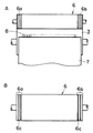
前述した図1の構成からなる回転ドラム型磁気分離装置において、図2Aに示す絞りローラー6には、その両端部に液濡れ部6a,6bが発生していたが、図2Bに示すように同部6a,6bに幅0.1mm、深さ10mmの溝部6cを2本ずつ設けたところ、液濡れ部は最も端の溝部6cより外側の部分のみに減少し、スクレパー7にて掻きとられるスラッジ8が液濡れすることが大幅に減少した。
【0021】
実施例3
図3Aに示すごとく、回転ドラム3に当接させるスクレパー9に、内径0.5mmの小孔9aを1mm間隔で穿孔したパンチングメタルを使用したところ、分離回収されるスラッジ8の重量が穿孔のない従来に比較して8%軽減され、液切れが大きく向上したことが分かる。又、パンチングメタルによるスクレパーは、無負荷時の液切れに関し、従来のスクレパーに比べて71%向上した。
【0022】
【発明の効果】
この発明による回転ドラム型磁気分離装置は、回転ドラム表面の所要深さの表層を改質処理、具体的にはフェライト化して磁性体化することにより、スラッジには磁石の磁力による吸着力以外に、磁石により一時的に磁石化する回転ドラム表面からの吸着力が作用し、回転ドラム表面の摩擦力に対向して搬送力が向上してスラッジの搬送不良の発生を低減し、あるいはさらに絞りローラーに周方向の溝部を設けて、ローラー両端部の液濡れを低減し、穿孔内径を選定したパンチングメタルをスクレパーに用いて液切れを向上させることができ、各手段は個別に有効であるが併用することにより、搬送能力並びに固液分離効率が相乗効果により一段と向上する。
【図面の簡単な説明】
【図1】この発明による回転ドラム型磁気分離装置の全体構成を示す縦断説明図である。
【図2】図2Aは回転ドラム型磁気分離装置の回転ドラムと絞りローラーとの位置関係の詳細を示す説明図であり、図2Bはこの発明による絞りローラーの説明図である。
【図3】図3Aは回転ドラム型磁気分離装置の回転ドラムと絞りローラーとスクレパーの位置関係の詳細を示す説明図であり、図3Bはこの発明によるスクレパーの詳細を示す説明図である。
【符号の説明】
1 本体
2 液溜め部
3 回転ドラム
4 磁石
5 内筒
6 絞りローラー
6a,6b 液濡れ部
6c 溝部
7,9 スクレパー
8 スラッジ
9a 小孔[0001]
BACKGROUND OF THE INVENTION
The present invention relates to a rotary drum type magnetic separation device that efficiently collects fine sludge from a coolant liquid and improves sludge drainage. Improves the occurrence of sludge separation and conveyance failure, and also provides a circumferential groove on the squeeze roller to reduce liquid wetting at both ends of the roller, and improves punching by using punching metal as a scraper. The present invention relates to a rotary drum type magnetic separation apparatus excellent in separation / conveying capacity and solid-liquid separation efficiency.
[0002]
[Prior art]
In cutting and grinding of a magnetic material such as a metal material, particularly a steel material, cutting waste and chips discharged together with the coolant liquid are usually separated and collected into a liquid component and cutting waste and chips. Various magnetic sorting apparatuses have been proposed according to the shape of cutting waste and chips. For example, chips called sludge are easily powdered and easily gathered to contain liquid components and are difficult to separate and collect. Therefore, an apparatus that has excellent ability to separate and recover fine sludge is required. That is, in a rotating drum type magnetic separation apparatus that has been put into practical use as a configuration suitable for ordinary sludge separation, it is difficult to separate and collect fine sludge, and an improvement thereof is required.
[0003]
In the rotary drum type magnetic separation apparatus shown in FIG. 1, a
[0004]
Various configurations can be adopted as the range in which the magnetic force is applied to the rotating
[0005]
A
[0006]
[Problems to be solved by the invention]
In the magnetic separation device having a structure in which the inner cylinder of the magnet is built in the rotating drum, the mechanism for transporting the sludge has a sludge because the friction force between the sludge and the outer cylinder surpasses the force by which the magnet attracts the sludge. Is considered to be transported. If the surface roughness of the surface of the rotating drum becomes too good, the sludge transport capacity will decrease, and if the surface roughness becomes poor, the liquid will tend to drop out. There is a predetermined range based on the correlation with the shape.
[0007]
In addition, in the case of poor conveyance, when the sludge has already gathered into a lump or fluff when flowing into the separation device, or when the sludge itself is too large, fine sludge has gathered into a lump or floc In order to eliminate such a conveyance failure, it is conceivable to increase the frictional force between the sludge and the outer cylinder surface or increase the adsorption force. However, the above-mentioned surface roughness has an optimum range, and the improvement of the attractive force can increase the amount of magnets or improve the performance, but a balance between both is required.
[0008]
On the other hand, the scraper is in full contact with the rotating drum, scraping off the sludge and scraping off the liquid on the drum surface, resulting in a sludge containing liquid. In addition, the squeezing roller has a low squeezing efficiency at both ends, and the surface tends to get wet, and the liquid in this part is sucked up by the sludge at the scraper part, which causes the problem that the liquid of the separated sludge becomes poor. there were.
[0009]
An object of the present invention is to solve the problems of the conventional rotary drum type magnetic separation device described above, and occurs when fine sludge is gathered into a lump or flocculent when flowing into the separation device or after flowing into the separation device. An object of the present invention is to provide a rotating drum type magnetic separation device that can eliminate a conveyance failure and has an excellent separation and collection ability of fine sludge, and also has a structure in which excellent drainage is sustainable.
[0010]
[Means for Solving the Problems]
Inventors, a result of various studies for construction of the rotating drum for the purpose of eliminating the conveyance failure, for example, the required depth of the rotary drum surface made of non-magnetic material only, ferrite of the tissue, by martensite of In addition to the attractive force due to the magnetic force of the magnet, the attractive force from the rotating drum surface that is temporarily magnetized by the magnet acts on the sludge, and the conveying force is improved against the frictional force on the rotating drum surface, that is, It has been found that the frictional force between the sludge and the surface of the rotating drum is increased by the amount of the attracting force generated on the surface of the rotating drum, which exceeds the force of attracting the sludge of the magnet and can reduce the conveyance failure.
[0011]
Further, as a result of various studies on the configuration of the scraper and the squeezing roller for the purpose of improving the liquid breakage, the inventor has found that the scraper is in full contact with the rotating drum. It has been found that liquid scraping can be improved by forming a scraper using a so-called punching plate and reducing the contact area to separate the liquid to be scraped off.
[0012]
Furthermore, as a result of various investigations aimed at improving the wet state of both ends of the squeeze roller, the inventor controls the width at which the liquid wetted part occurs by inserting grooves and slits at both ends of the squeeze roller. We have found that we can control the liquid wetting part width from the end face according to the pressing force and rotation speed of the roller, and the type of liquid by appropriately selecting the width, depth, number, and interval of the slit, and completed this invention. did.
[0013]
DETAILED DESCRIPTION OF THE INVENTION
In the present invention, a magnetic material having a required depth on the surface of the rotating drum is made into a magnetic material, and an attractive force from the drum surface is applied to the sludge in addition to the magnetic attractive force from the magnet. It increases by the amount of attraction force from the surface, exceeds the attraction force from the magnet drum, and reduces conveyance defects.
[0014]
In the present invention, the means for forming a magnetic material only for the required depth of the surface of the rotating drum is a modification treatment for ferritization or martensite treatment, for example, nitriding heat treatment, and a magnetic material sheet such as ferrite is attached or sandwiched. It is possible to provide the entire surface of the rotating drum, only a required portion, or a required pattern. The thickness of the magnetic layer is 10 μm to 0.5 mm, preferably 20 μm to 80 μm.
[0015]
Among the above reforming treatments, the nitriding heat treatment conditions are appropriately selected according to the material to be treated, but a treatment of holding at 300 ° C. to 700 ° C. for 30 minutes to 24 hours in a nitrogen-containing atmosphere is preferable.
[0016]
In the present invention, at least one circumferential groove is provided at both ends of the squeeze roller, because of the structure of the squeeze roller, it is difficult for a pressing force to act on both ends, resulting in poor squeezing efficiency. , where the required width, the liquid fraction by the groove depth in the circumferential direction s provided is discharged also the rotation enters the groove, the liquid wetting is reduced. The liquid wetting part width from the end face can be controlled by appropriately selecting the width, depth, number, and interval of the slits according to the pressing force and rotation number of the roller, and the type of liquid. In the case of 130 mm, the slit width is about 0.1 mm, the depth is 5 to 15 mm, and it is preferable to arrange them at intervals of about 5 mm.
[0017]
In the present invention, by using a plate material in which a plurality of holes having a required inner diameter are arranged in the scraper, the liquid component is discharged from the holes arranged in the plate material so that the liquid component does not return to the scraped sludge. Hole shape and dimensions as well as the sequence method sludge dimensions, but appropriately selected depending on the liquid type, for example, a round hole with an inner diameter of 0.5mm several to several tens / cm 2, is to staggered preferable.
[0018]
【Example】
Example 1
In the rotary drum type magnetic separation apparatus having the configuration shown in FIG. 1 described above, a ferrite structure having a surface layer thickness of 30 μm is formed on the surface of the rotary drum made of stainless steel by nitriding heat treatment under the condition of a temperature of 530 ° C., a nitrogen-containing atmosphere for 4 hours. Formed on the entire surface.
[0019]
In the separation apparatus according to the present invention described above, when the magnetic separation is carried out from only water containing sludge having a size of 20 μm to 1000 μm or from three kinds of water-soluble and oil-based coolant liquids, the rotating drum is used in any case. Compared with the conventional apparatus which does not form a ferrite structure on the surface, it can be seen that the conveyance failure of sludge aggregated in a lump or cotton shape is reduced by 70%, and the conveyance capability is greatly improved.
[0020]
Example 2
In the rotary drum type magnetic separation apparatus having the configuration shown in FIG. 1, the squeezing
[0021]
Example 3
As shown in FIG. 3A, when a punching metal having
[0022]
【The invention's effect】
The rotating drum type magnetic separation device according to the present invention has a surface layer of a required depth on the surface of the rotating drum that is modified , specifically ferritized into a magnetic material, so that the sludge has an attractive force other than the magnetic force of the magnet. The suction force from the surface of the rotating drum that is temporarily magnetized by the magnet acts, and the conveying force is improved against the frictional force on the surface of the rotating drum to reduce the occurrence of sludge conveyance failure, or the squeezing roller A circumferential groove is provided to reduce liquid wetting at both ends of the roller, and a punching metal with a selected bore diameter can be used as a scraper to improve fluid breakage. By doing so, the conveyance capacity and the solid-liquid separation efficiency are further improved by a synergistic effect.
[Brief description of the drawings]
FIG. 1 is a longitudinal explanatory view showing the entire configuration of a rotary drum type magnetic separation device according to the present invention.
FIG. 2A is an explanatory diagram showing details of the positional relationship between the rotary drum and the squeezing roller of the rotary drum type magnetic separation device, and FIG. 2B is an explanatory diagram of the squeezing roller according to the present invention.
FIG. 3A is an explanatory view showing details of a positional relationship among a rotary drum, a squeezing roller and a scraper of the rotary drum type magnetic separation device, and FIG. 3B is an explanatory view showing details of the scraper according to the present invention.
[Explanation of symbols]
DESCRIPTION OF SYMBOLS 1
Claims (3)
Priority Applications (1)
| Application Number | Priority Date | Filing Date | Title |
|---|---|---|---|
| JP26733398A JP4289517B2 (en) | 1998-09-04 | 1998-09-04 | Rotating drum type magnetic separator |
Applications Claiming Priority (1)
| Application Number | Priority Date | Filing Date | Title |
|---|---|---|---|
| JP26733398A JP4289517B2 (en) | 1998-09-04 | 1998-09-04 | Rotating drum type magnetic separator |
Publications (3)
| Publication Number | Publication Date |
|---|---|
| JP2000079353A JP2000079353A (en) | 2000-03-21 |
| JP2000079353A5 JP2000079353A5 (en) | 2005-11-17 |
| JP4289517B2 true JP4289517B2 (en) | 2009-07-01 |
Family
ID=17443369
Family Applications (1)
| Application Number | Title | Priority Date | Filing Date |
|---|---|---|---|
| JP26733398A Expired - Fee Related JP4289517B2 (en) | 1998-09-04 | 1998-09-04 | Rotating drum type magnetic separator |
Country Status (1)
| Country | Link |
|---|---|
| JP (1) | JP4289517B2 (en) |
Families Citing this family (14)
| Publication number | Priority date | Publication date | Assignee | Title |
|---|---|---|---|---|
| CN100553785C (en) | 2005-04-28 | 2009-10-28 | 株式会社日立制作所 | Magnetic separation cleaning apparatus and magnetic separation cleaning method |
| JP4948514B2 (en) * | 2007-12-28 | 2012-06-06 | 住友重機械ファインテック株式会社 | Rotating drum type magnetic separator |
| JP4785913B2 (en) * | 2007-12-28 | 2011-10-05 | 住友重機械ファインテック株式会社 | Rotating drum type magnetic separator |
| JP4810549B2 (en) * | 2008-02-08 | 2011-11-09 | 株式会社ブンリ | Magnetic separator |
| JP6218390B2 (en) * | 2013-02-14 | 2017-10-25 | 住友重機械ファインテック株式会社 | Rotating drum and method of manufacturing the rotating drum |
| KR101498258B1 (en) * | 2013-08-14 | 2015-03-05 | (주)스텝이엔지 | Apparatus for separating iron powders |
| CN103464397A (en) * | 2013-09-03 | 2013-12-25 | 宁夏共享集团有限责任公司 | Auto-adjust chip scraper |
| JP2015199989A (en) * | 2014-04-08 | 2015-11-12 | 住友金属鉱山株式会社 | Liquid draining device, electric plating apparatus and production method of copper-clad laminated resin film |
| CN104984815B (en) * | 2015-05-28 | 2016-04-27 | 张宝祥 | A kind of wet type beneficiation method |
| CN104841550B (en) * | 2015-05-28 | 2016-04-27 | 张宝祥 | A kind of resource of tailings recovery process |
| CN107755087B (en) * | 2017-11-27 | 2024-03-08 | 远诺过滤技术(上海)有限公司 | Full-automatic magnetic filter |
| EP3843902A4 (en) * | 2018-08-31 | 2021-11-17 | GT of Ohio, Ltd | Method and apparatus for continuous magnetic filtration of ferrous mill scale from liquid solutions |
| JP7146685B2 (en) * | 2019-03-29 | 2022-10-04 | 住友重機械ファインテック株式会社 | Drum separator |
| CN112495581A (en) * | 2020-12-22 | 2021-03-16 | 崇义县鑫成矿业有限公司 | Tin ore coarse fodder iron sieving mechanism |
Family Cites Families (3)
| Publication number | Priority date | Publication date | Assignee | Title |
|---|---|---|---|---|
| JPH08369Y2 (en) * | 1989-06-28 | 1996-01-10 | 川崎製鉄株式会社 | Liquid draining structure of squeezing roll |
| JPH045242U (en) * | 1990-04-24 | 1992-01-17 | ||
| JP2756097B2 (en) * | 1995-07-14 | 1998-05-25 | 株式会社ブンリ | Filtration device |
-
1998
- 1998-09-04 JP JP26733398A patent/JP4289517B2/en not_active Expired - Fee Related
Also Published As
| Publication number | Publication date |
|---|---|
| JP2000079353A (en) | 2000-03-21 |
Similar Documents
| Publication | Publication Date | Title |
|---|---|---|
| JP4289517B2 (en) | Rotating drum type magnetic separator | |
| JP5115219B2 (en) | Magnetic separation device | |
| JP2009183923A (en) | Magnetic separator | |
| CN201495120U (en) | Magnetic water treatment equipment | |
| JP4948514B2 (en) | Rotating drum type magnetic separator | |
| JP3533622B2 (en) | Magnetic separator for needle chip control | |
| JP2003340717A (en) | Oil skimmer having floating chip collecting function | |
| JPS6323962Y2 (en) | ||
| JP5479046B2 (en) | Separation apparatus and separation method for grinding sludge contained in grinding fluid | |
| CN207391076U (en) | A kind of magnetic loading sludge collects separation equipment | |
| JP2001334170A (en) | Magnetic metallic chip recovering device | |
| US4025433A (en) | Magnetic separating apparatus | |
| JP2005058880A (en) | Sludge separator | |
| JP2001029838A (en) | Method for partially attenuating magnetism of turnings separator and ferrous turnings separator | |
| JP3841382B2 (en) | Metal powder removal device | |
| JPS63192510A (en) | Water absorption ringer roll | |
| JPH10244424A (en) | Chip separation device for electrical discharge machine | |
| JPH1133871A (en) | Chip separating device of electric discharge machine | |
| CN216025513U (en) | Swivel for vertical ring high-gradient magnetic separator | |
| CN104888957B (en) | Paper tape type separator | |
| JP3052843U (en) | Magnetic separator | |
| CN109052906A (en) | The sludge treatment equipment of pore sludge is cleared up by the wire on soft hollow billet | |
| JPS6234574Y2 (en) | ||
| JP2601469Y2 (en) | Iron-based chip separation equipment | |
| JP3799390B2 (en) | Purification device using magnetic material |
Legal Events
| Date | Code | Title | Description |
|---|---|---|---|
| A521 | Written amendment |
Free format text: JAPANESE INTERMEDIATE CODE: A523 Effective date: 20050831 |
|
| A621 | Written request for application examination |
Free format text: JAPANESE INTERMEDIATE CODE: A621 Effective date: 20050831 |
|
| A711 | Notification of change in applicant |
Free format text: JAPANESE INTERMEDIATE CODE: A711 Effective date: 20050831 |
|
| RD02 | Notification of acceptance of power of attorney |
Free format text: JAPANESE INTERMEDIATE CODE: A7422 Effective date: 20050831 |
|
| A521 | Written amendment |
Free format text: JAPANESE INTERMEDIATE CODE: A821 Effective date: 20050831 |
|
| RD02 | Notification of acceptance of power of attorney |
Free format text: JAPANESE INTERMEDIATE CODE: A7422 Effective date: 20070315 |
|
| RD05 | Notification of revocation of power of attorney |
Free format text: JAPANESE INTERMEDIATE CODE: A7425 Effective date: 20070404 |
|
| A521 | Written amendment |
Free format text: JAPANESE INTERMEDIATE CODE: A523 Effective date: 20070612 |
|
| A131 | Notification of reasons for refusal |
Free format text: JAPANESE INTERMEDIATE CODE: A131 Effective date: 20080812 |
|
| A521 | Written amendment |
Free format text: JAPANESE INTERMEDIATE CODE: A523 Effective date: 20081003 |
|
| TRDD | Decision of grant or rejection written | ||
| A01 | Written decision to grant a patent or to grant a registration (utility model) |
Free format text: JAPANESE INTERMEDIATE CODE: A01 Effective date: 20090326 |
|
| A01 | Written decision to grant a patent or to grant a registration (utility model) |
Free format text: JAPANESE INTERMEDIATE CODE: A01 |
|
| A61 | First payment of annual fees (during grant procedure) |
Free format text: JAPANESE INTERMEDIATE CODE: A61 Effective date: 20090326 |
|
| R150 | Certificate of patent or registration of utility model |
Free format text: JAPANESE INTERMEDIATE CODE: R150 |
|
| FPAY | Renewal fee payment (event date is renewal date of database) |
Free format text: PAYMENT UNTIL: 20120410 Year of fee payment: 3 |
|
| FPAY | Renewal fee payment (event date is renewal date of database) |
Free format text: PAYMENT UNTIL: 20120410 Year of fee payment: 3 |
|
| FPAY | Renewal fee payment (event date is renewal date of database) |
Free format text: PAYMENT UNTIL: 20130410 Year of fee payment: 4 |
|
| FPAY | Renewal fee payment (event date is renewal date of database) |
Free format text: PAYMENT UNTIL: 20130410 Year of fee payment: 4 |
|
| FPAY | Renewal fee payment (event date is renewal date of database) |
Free format text: PAYMENT UNTIL: 20140410 Year of fee payment: 5 |
|
| R250 | Receipt of annual fees |
Free format text: JAPANESE INTERMEDIATE CODE: R250 |
|
| R250 | Receipt of annual fees |
Free format text: JAPANESE INTERMEDIATE CODE: R250 |
|
| LAPS | Cancellation because of no payment of annual fees |