JP4288449B2 - Image display device, image processing device, and image display system - Google Patents
Image display device, image processing device, and image display system Download PDFInfo
- Publication number
- JP4288449B2 JP4288449B2 JP2000600243A JP2000600243A JP4288449B2 JP 4288449 B2 JP4288449 B2 JP 4288449B2 JP 2000600243 A JP2000600243 A JP 2000600243A JP 2000600243 A JP2000600243 A JP 2000600243A JP 4288449 B2 JP4288449 B2 JP 4288449B2
- Authority
- JP
- Japan
- Prior art keywords
- image
- input
- moving
- image display
- viewpoint
- Prior art date
- Legal status (The legal status is an assumption and is not a legal conclusion. Google has not performed a legal analysis and makes no representation as to the accuracy of the status listed.)
- Expired - Fee Related
Links
Images


Classifications
-
- A—HUMAN NECESSITIES
- A63—SPORTS; GAMES; AMUSEMENTS
- A63F—CARD, BOARD, OR ROULETTE GAMES; INDOOR GAMES USING SMALL MOVING PLAYING BODIES; VIDEO GAMES; GAMES NOT OTHERWISE PROVIDED FOR
- A63F13/00—Video games, i.e. games using an electronically generated display having two or more dimensions
- A63F13/50—Controlling the output signals based on the game progress
- A63F13/53—Controlling the output signals based on the game progress involving additional visual information provided to the game scene, e.g. by overlay to simulate a head-up display [HUD] or displaying a laser sight in a shooting game
-
- G—PHYSICS
- G06—COMPUTING; CALCULATING OR COUNTING
- G06T—IMAGE DATA PROCESSING OR GENERATION, IN GENERAL
- G06T13/00—Animation
- G06T13/20—3D [Three Dimensional] animation
- G06T13/40—3D [Three Dimensional] animation of characters, e.g. humans, animals or virtual beings
-
- A—HUMAN NECESSITIES
- A63—SPORTS; GAMES; AMUSEMENTS
- A63F—CARD, BOARD, OR ROULETTE GAMES; INDOOR GAMES USING SMALL MOVING PLAYING BODIES; VIDEO GAMES; GAMES NOT OTHERWISE PROVIDED FOR
- A63F13/00—Video games, i.e. games using an electronically generated display having two or more dimensions
- A63F13/20—Input arrangements for video game devices
- A63F13/21—Input arrangements for video game devices characterised by their sensors, purposes or types
- A63F13/214—Input arrangements for video game devices characterised by their sensors, purposes or types for locating contacts on a surface, e.g. floor mats or touch pads
- A63F13/2145—Input arrangements for video game devices characterised by their sensors, purposes or types for locating contacts on a surface, e.g. floor mats or touch pads the surface being also a display device, e.g. touch screens
-
- A—HUMAN NECESSITIES
- A63—SPORTS; GAMES; AMUSEMENTS
- A63F—CARD, BOARD, OR ROULETTE GAMES; INDOOR GAMES USING SMALL MOVING PLAYING BODIES; VIDEO GAMES; GAMES NOT OTHERWISE PROVIDED FOR
- A63F13/00—Video games, i.e. games using an electronically generated display having two or more dimensions
- A63F13/25—Output arrangements for video game devices
-
- A—HUMAN NECESSITIES
- A63—SPORTS; GAMES; AMUSEMENTS
- A63F—CARD, BOARD, OR ROULETTE GAMES; INDOOR GAMES USING SMALL MOVING PLAYING BODIES; VIDEO GAMES; GAMES NOT OTHERWISE PROVIDED FOR
- A63F13/00—Video games, i.e. games using an electronically generated display having two or more dimensions
- A63F13/40—Processing input control signals of video game devices, e.g. signals generated by the player or derived from the environment
- A63F13/42—Processing input control signals of video game devices, e.g. signals generated by the player or derived from the environment by mapping the input signals into game commands, e.g. mapping the displacement of a stylus on a touch screen to the steering angle of a virtual vehicle
- A63F13/426—Processing input control signals of video game devices, e.g. signals generated by the player or derived from the environment by mapping the input signals into game commands, e.g. mapping the displacement of a stylus on a touch screen to the steering angle of a virtual vehicle involving on-screen location information, e.g. screen coordinates of an area at which the player is aiming with a light gun
-
- A—HUMAN NECESSITIES
- A63—SPORTS; GAMES; AMUSEMENTS
- A63F—CARD, BOARD, OR ROULETTE GAMES; INDOOR GAMES USING SMALL MOVING PLAYING BODIES; VIDEO GAMES; GAMES NOT OTHERWISE PROVIDED FOR
- A63F13/00—Video games, i.e. games using an electronically generated display having two or more dimensions
- A63F13/50—Controlling the output signals based on the game progress
- A63F13/52—Controlling the output signals based on the game progress involving aspects of the displayed game scene
- A63F13/525—Changing parameters of virtual cameras
-
- A—HUMAN NECESSITIES
- A63—SPORTS; GAMES; AMUSEMENTS
- A63F—CARD, BOARD, OR ROULETTE GAMES; INDOOR GAMES USING SMALL MOVING PLAYING BODIES; VIDEO GAMES; GAMES NOT OTHERWISE PROVIDED FOR
- A63F13/00—Video games, i.e. games using an electronically generated display having two or more dimensions
- A63F13/55—Controlling game characters or game objects based on the game progress
- A63F13/56—Computing the motion of game characters with respect to other game characters, game objects or elements of the game scene, e.g. for simulating the behaviour of a group of virtual soldiers or for path finding
-
- A—HUMAN NECESSITIES
- A63—SPORTS; GAMES; AMUSEMENTS
- A63F—CARD, BOARD, OR ROULETTE GAMES; INDOOR GAMES USING SMALL MOVING PLAYING BODIES; VIDEO GAMES; GAMES NOT OTHERWISE PROVIDED FOR
- A63F13/00—Video games, i.e. games using an electronically generated display having two or more dimensions
- A63F13/55—Controlling game characters or game objects based on the game progress
- A63F13/57—Simulating properties, behaviour or motion of objects in the game world, e.g. computing tyre load in a car race game
- A63F13/577—Simulating properties, behaviour or motion of objects in the game world, e.g. computing tyre load in a car race game using determination of contact between game characters or objects, e.g. to avoid collision between virtual racing cars
-
- A—HUMAN NECESSITIES
- A63—SPORTS; GAMES; AMUSEMENTS
- A63F—CARD, BOARD, OR ROULETTE GAMES; INDOOR GAMES USING SMALL MOVING PLAYING BODIES; VIDEO GAMES; GAMES NOT OTHERWISE PROVIDED FOR
- A63F13/00—Video games, i.e. games using an electronically generated display having two or more dimensions
- A63F13/55—Controlling game characters or game objects based on the game progress
- A63F13/58—Controlling game characters or game objects based on the game progress by computing conditions of game characters, e.g. stamina, strength, motivation or energy level
-
- A—HUMAN NECESSITIES
- A63—SPORTS; GAMES; AMUSEMENTS
- A63F—CARD, BOARD, OR ROULETTE GAMES; INDOOR GAMES USING SMALL MOVING PLAYING BODIES; VIDEO GAMES; GAMES NOT OTHERWISE PROVIDED FOR
- A63F13/00—Video games, i.e. games using an electronically generated display having two or more dimensions
- A63F13/80—Special adaptations for executing a specific game genre or game mode
- A63F13/818—Fishing
-
- G—PHYSICS
- G06—COMPUTING; CALCULATING OR COUNTING
- G06T—IMAGE DATA PROCESSING OR GENERATION, IN GENERAL
- G06T13/00—Animation
-
- A—HUMAN NECESSITIES
- A63—SPORTS; GAMES; AMUSEMENTS
- A63F—CARD, BOARD, OR ROULETTE GAMES; INDOOR GAMES USING SMALL MOVING PLAYING BODIES; VIDEO GAMES; GAMES NOT OTHERWISE PROVIDED FOR
- A63F2300/00—Features of games using an electronically generated display having two or more dimensions, e.g. on a television screen, showing representations related to the game
- A63F2300/10—Features of games using an electronically generated display having two or more dimensions, e.g. on a television screen, showing representations related to the game characterized by input arrangements for converting player-generated signals into game device control signals
- A63F2300/1068—Features of games using an electronically generated display having two or more dimensions, e.g. on a television screen, showing representations related to the game characterized by input arrangements for converting player-generated signals into game device control signals being specially adapted to detect the point of contact of the player on a surface, e.g. floor mat, touch pad
- A63F2300/1075—Features of games using an electronically generated display having two or more dimensions, e.g. on a television screen, showing representations related to the game characterized by input arrangements for converting player-generated signals into game device control signals being specially adapted to detect the point of contact of the player on a surface, e.g. floor mat, touch pad using a touch screen
-
- A—HUMAN NECESSITIES
- A63—SPORTS; GAMES; AMUSEMENTS
- A63F—CARD, BOARD, OR ROULETTE GAMES; INDOOR GAMES USING SMALL MOVING PLAYING BODIES; VIDEO GAMES; GAMES NOT OTHERWISE PROVIDED FOR
- A63F2300/00—Features of games using an electronically generated display having two or more dimensions, e.g. on a television screen, showing representations related to the game
- A63F2300/60—Methods for processing data by generating or executing the game program
- A63F2300/64—Methods for processing data by generating or executing the game program for computing dynamical parameters of game objects, e.g. motion determination or computation of frictional forces for a virtual car
- A63F2300/643—Methods for processing data by generating or executing the game program for computing dynamical parameters of game objects, e.g. motion determination or computation of frictional forces for a virtual car by determining the impact between objects, e.g. collision detection
-
- A—HUMAN NECESSITIES
- A63—SPORTS; GAMES; AMUSEMENTS
- A63F—CARD, BOARD, OR ROULETTE GAMES; INDOOR GAMES USING SMALL MOVING PLAYING BODIES; VIDEO GAMES; GAMES NOT OTHERWISE PROVIDED FOR
- A63F2300/00—Features of games using an electronically generated display having two or more dimensions, e.g. on a television screen, showing representations related to the game
- A63F2300/60—Methods for processing data by generating or executing the game program
- A63F2300/65—Methods for processing data by generating or executing the game program for computing the condition of a game character
-
- A—HUMAN NECESSITIES
- A63—SPORTS; GAMES; AMUSEMENTS
- A63F—CARD, BOARD, OR ROULETTE GAMES; INDOOR GAMES USING SMALL MOVING PLAYING BODIES; VIDEO GAMES; GAMES NOT OTHERWISE PROVIDED FOR
- A63F2300/00—Features of games using an electronically generated display having two or more dimensions, e.g. on a television screen, showing representations related to the game
- A63F2300/60—Methods for processing data by generating or executing the game program
- A63F2300/66—Methods for processing data by generating or executing the game program for rendering three dimensional images
- A63F2300/6607—Methods for processing data by generating or executing the game program for rendering three dimensional images for animating game characters, e.g. skeleton kinematics
-
- A—HUMAN NECESSITIES
- A63—SPORTS; GAMES; AMUSEMENTS
- A63F—CARD, BOARD, OR ROULETTE GAMES; INDOOR GAMES USING SMALL MOVING PLAYING BODIES; VIDEO GAMES; GAMES NOT OTHERWISE PROVIDED FOR
- A63F2300/00—Features of games using an electronically generated display having two or more dimensions, e.g. on a television screen, showing representations related to the game
- A63F2300/60—Methods for processing data by generating or executing the game program
- A63F2300/66—Methods for processing data by generating or executing the game program for rendering three dimensional images
- A63F2300/6623—Methods for processing data by generating or executing the game program for rendering three dimensional images for animating a group of characters
-
- A—HUMAN NECESSITIES
- A63—SPORTS; GAMES; AMUSEMENTS
- A63F—CARD, BOARD, OR ROULETTE GAMES; INDOOR GAMES USING SMALL MOVING PLAYING BODIES; VIDEO GAMES; GAMES NOT OTHERWISE PROVIDED FOR
- A63F2300/00—Features of games using an electronically generated display having two or more dimensions, e.g. on a television screen, showing representations related to the game
- A63F2300/60—Methods for processing data by generating or executing the game program
- A63F2300/66—Methods for processing data by generating or executing the game program for rendering three dimensional images
- A63F2300/6661—Methods for processing data by generating or executing the game program for rendering three dimensional images for changing the position of the virtual camera
-
- A—HUMAN NECESSITIES
- A63—SPORTS; GAMES; AMUSEMENTS
- A63F—CARD, BOARD, OR ROULETTE GAMES; INDOOR GAMES USING SMALL MOVING PLAYING BODIES; VIDEO GAMES; GAMES NOT OTHERWISE PROVIDED FOR
- A63F2300/00—Features of games using an electronically generated display having two or more dimensions, e.g. on a television screen, showing representations related to the game
- A63F2300/80—Features of games using an electronically generated display having two or more dimensions, e.g. on a television screen, showing representations related to the game specially adapted for executing a specific type of game
- A63F2300/8035—Virtual fishing
-
- A—HUMAN NECESSITIES
- A63—SPORTS; GAMES; AMUSEMENTS
- A63F—CARD, BOARD, OR ROULETTE GAMES; INDOOR GAMES USING SMALL MOVING PLAYING BODIES; VIDEO GAMES; GAMES NOT OTHERWISE PROVIDED FOR
- A63F2300/00—Features of games using an electronically generated display having two or more dimensions, e.g. on a television screen, showing representations related to the game
- A63F2300/80—Features of games using an electronically generated display having two or more dimensions, e.g. on a television screen, showing representations related to the game specially adapted for executing a specific type of game
- A63F2300/8058—Virtual breeding, e.g. tamagotchi
Description
技術分野
本発明は、画像表示装置、画像処理装置、画像表示システムに関する。
背景技術
▲1▼ 従来、画像表示装置を備えた遊戯装置の分野において、画像表示装置に魚その他の移動体を表示させ、これを疑似ペットのように観賞する観賞遊戯装置が存在する。この観賞遊戯装置に備えられる画像処理装置においては、仮想3次元空間上に移動体を模した仮想のモデルを形成し、これを所定の視点から見た映像を表示手段に表示させることができる。
しかし、視点や注視点を固定させると背景画面に変化がなく、立体感の表現が不十分となる。また、視点や注視点の動きが画一的になると、背景画面の変化も画一的となり、観察者の興味を減じる可能性がある。一方、視点や注視点をランダムに動かすと、その視野に移動体が入らなかったり、視野の中心部に移動体が入らずに観察者の興味を減じることになる可能性がある。
▲2▼ さらに、視野に入った場合でも、視点と移動体との距離が長すぎたり短すぎたりすると観察者の興味を減じるおそれがある。また、移動体が向いている方向や移動している方向も考慮して視点や注視点の位置を設定した方が、より見易い画像とすることができる。さらに、移動体の動きが急激に変化した時は、視点や注視点の動きを緩和した方が、見易い画像となる。
▲3▼ 更に、移動体の動きに依存して視点を動かす場合、移動体の動きが少ないと、視点の動きも少なくなり、観察者の興味を減じるおそれがある。
▲4▼ また、仮想空間上のモデルを所定の視点から見た場合の映像を表示する画像表示システムにおいて、当該モデルに仮想の光を当てた場合の様子を表示することのできる画像表示システムが知られている。
しかし、光を当てて明るくする部分を、画面上で簡単かつ自由に設定できるものは知られていない。
▲5▼ また、画像表示装置に表示された画像上の所定部分にマウスポインタを移動させてマウスをクリックすると、当該画像上の所定部分に表示されているものに関する説明が表示される画像表示システムは知られている。
しかし、複数の魚その他の動植物の画像を画像表示装置に表示させ、これを疑似ペットのように観賞する観賞用画像表示システムにおいて、各移動体の情報表示を行なうものは存在しない。
▲6▼ また、例えば潜水艦の中から窓を通して外を見た場合の映像を観賞用画像として画像表示装置に表示させる場合、窓枠の画像を、窓の外の画像と共に表示することにより、画像に現実性を持たせることが考えられる。
しかし、窓枠の画像を表示しても、窓枠の厚みまで表現することはできないので、現実性に欠ける映像となり、観賞用画像として物足りないものとなるおそれがある。
▲7▼ また、画像表示装置の画面上に入力手段を備え、付属の入力ペンその他で画面をなぞると、なぞった通りの線図を描画できる表示システムが知られている。
しかし、なぞった軌跡上に複数の移動体を配列させ、これら複数の移動体により描画するものは従来存在しない。
▲8▼ また、予め記録された図形又は文字を表示装置に表示し、一定時間ごとに、予め記録された他の図形又は文字に更新可能な表示システムは知られている。
しかし、複数の魚その他の移動体を画像表示装置に表示させ、これを疑似ペットのように観賞する観賞遊戯装置において、当該複数の移動体の配列によって線図(文字、図形等)を表示するものは知られていない。
▲9▼ また、従来、画像表示装置の分野において、CRT、液晶等の画像表示装置が存在する。しかし、CRTはブラウン管を利用するので、特に大きな画面を設けようとすると奥行きの寸法も大きくする必要があり(図1参照)、広い設置スペースが必要である。また、液晶による画像表示装置は高価であり、特に大きな画面にしようとすればコストが嵩む。また、入力装置としてジョイスティックや各種操作ボタンを設けると、より広い設置スペースが必要である。更に、CRTでは36インチが限界とされ、より大きな画面を実現することはできない。
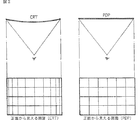
また、CRTのように画像表示面が湾曲していると、画像のうち表示面の端部に映された部分が歪んで見える(図2参照)。特に3次元CGによる画像を表示する場合には、画像の歪みが立体感の表現を損なうという問題がある。また、ある程度離れた距離から見れば、画像端部の歪みは少なくなるが、画面に近づいて見た場合は画像の歪みが大きい。特に画面にタッチセンサを設けて画像観察者と画面とのインタラクティブ性を充実させようとすると、画像観察者は画面に近づいて画像を見ることにならざるを得ず、画像の歪みが無視できない問題となる。
そこで本発明は、複数の移動体が動く様子を示す観賞用画像を生成する観賞遊戯装置等において、遊戯性の高い遊戯装置を提供することを目的とし、より詳しくは以下の事項を目的とする。
第1に、前記1つの移動体又は移動体群の状態に基いて視点位置を決定することによって、視点の位置を少なくとも1つの魚に対して適切な位置に保持し、少なくとも当該1つの魚を適切に表示可能にすることにより、仮想空間上を動き回る移動体を、観察者の興味を減じないように適切に表示することができる画像処理装置を提供することを目的とする。
第2に、移動体を確実に表示させるように視点及び視線を設定することにより、仮想空間上を動き回る移動体を、観察者の興味を減じないように適切に表示することができる画像処理装置を提供することを目的とする。
第3に、画像に変化を持たせることにより、仮想空間上を動き回る移動体を、観察者の興味を減じないように適切に表示することができる画像処理装置を提供することを目的とする。
第4に、画面上で所定の入力をするだけで、明るくする部分を選択できる画像表示システムを提供することを目的とする。
第5に、本発明は、複数の魚その他の移動体を画像表示装置に表示させ、これを疑似ペットのように観賞する観賞遊戯装置において、これら複数の移動体のそれぞれについて容易に説明を表示させることができるようにすることにより、観賞をより楽しく分かり易いものにすることを目的とする。
第6に、本発明は、現実性に富んだ画像を表示可能な観賞用画像表示装置を提供することを目的とする。
第7に、画面をなぞった軌跡に従って描画された画像を表示する画像表示システムにおいて、新たな表現方法を提供することを目的とする。また、観賞用画像表示システムにおいてなぞった軌跡に従って移動体を任意の配列に並べさせることを可能とし、遊戯性を付加することを目的とする。
第8に、本発明は、複数の魚その他の移動体を画像表示装置に表示させ、これを疑似ペットのように観賞する観賞遊戯装置において、通常の状態では移動体に自然な動きをさせて観賞に堪えるようにするとともに、一定モードにおいては複数の移動体に所定の配置をさせ、全体で所定の線図(文字、図形等)を示すようにし、観賞の面白味を加えることを目的とする。
第9に、設置スペースを小さくしつつ大画面化が可能な画像表示装置を提供することを目的とする。また、大画面でかつ画像の歪みのない画像表示装置を提供することを目的とする。
発明の開示
上記の目的を達成するため、本発明は、仮想3次元空間内を動く複数の移動体を所定の視点から見た場合の映像を表示手段に表示させる画像処理装置であって、前記複数の移動体の中から選択された1つの移動体又は1つのまとまった動きをする移動体群の状態に基いて前記視点の位置を設定することを特徴とする。
また、前記1つの移動体又は移動体群の状態に基いて前記視点からの視線の方向を設定することが望ましい。
また、前記視点の位置は、所定時間毎に前記1つの移動体又は移動体群を基準としたものから他の1つの移動体又は移動体群を基準としたものに切り換えることが望ましい。
また、本発明の画像処理装置は、仮想3次元空間内を動く複数の移動体をそれぞれ模した仮想モデルを形成する移動体モデル形成手段と、前記複数の移動体の中から1つの移動体又は1つのまとまった動きをする移動体群を選択する移動体選択手段と、当該1つの移動体又は移動体群の状態を認識する状態認識手段と、前記1つの移動体又は移動体群の状態に基いて視点の位置を設定する視点位置設定手段と、前記視点から前記複数の移動体の全部又は一部を見た場合の映像を生成する映像生成手段とを備えたことを特徴とする。
また、前記1つの移動体又は移動体群の状態に基いて視線の方向を設定する視線方向設定手段を更に備え、前記映像生成手段は、前記視点から前記視線の方向を見た場合の映像を生成することが望ましい。
また、本発明は、仮想3次元空間内を動く1つ又は複数の移動体を所定の視点から見た場合の映像を表示手段に表示させる画像処理装置であって、前記1つ又は複数の移動体のうち1つの移動体又は1つのまとまった動きをする移動体群の向きが前記視点から遠ざかる方向である場合に設定される視点の前記1つの移動体又は移動体群との距離は、前記1つの移動体又は移動体群の向きが前記視点に近づく方向である場合に設定される視点の前記1つの移動体又は移動体群との距離に比べて短いことを特徴とする。
また、本発明の画像処理装置は、仮想3次元空間内を動く1つ又は複数の移動体をそれぞれ模した仮想モデルを形成する移動体モデル形成手段と、前記1つ又は複数の移動体のうち1つの移動体又は1つのまとまった動きをする移動体群の状態を認識する状態認識手段と、前記1つの移動体又は移動体群の状態に基いて視点の位置を設定する視点位置設定手段と、前記視点から前記複数の移動体の全部又は一部を見た場合の映像を生成する映像生成手段とを備えた画像処理装置であって、前記状態認識手段は、前記1つの移動体又は移動体群の位置(Pf)および向き(Vf)を認識し、前記視点位置設定手段は、前記1つの移動体又は移動体群の位置および向きに基いて視点の位置(Pn)を設定することを特徴とする。
また、前記視点位置設定手段は、前記1つの移動体又は移動体群の向き(Vf)に基いて所定の基準方向(V’f)を算出し、前記1つの移動体又は移動体群の位置(Pf)から前記所定の基準方向(V’f)に向かって所定距離(Lf)離れた位置(Bf)を含む平面から所定距離(Ls)離れた位置(B’)を算出し、これに基いて前記視点の位置(Pn)を設定することが望ましい。
また、本発明は、仮想3次元空間内を動く1つ又は複数の移動体を所定の視点から見た場合の映像を表示手段に表示させる画像処理装置であって、前記1つ又は複数の移動体のうち1つの移動体又は1つのまとまった動きをする移動体群の状態に基いて前記視点の位置を設定し、前記1つの移動体又は移動体群の状態に基いて前記視点からの視線の方向を設定し、前記視線の方向は、前記1つの移動体又は移動体群が移動している時は、前記1つの移動体又は移動体群の移動方向前方の位置を向くことを特徴とする。
また、本発明の画像処理装置は、仮想3次元空間内を動く1つ又は複数の移動体をそれぞれ模した仮想モデルを形成する移動体モデル形成手段と、前記1つ又は複数の移動体のうち1つの移動体又は1つのまとまった動きをする移動体群の状態を認識する状態認識手段と、前記1つの移動体又は移動体群の状態に基いて視点の位置を設定する視点位置設定手段と、前記1つの移動体又は移動体群の状態に基いて視線の方向を設定する視線方向設定手段と、前記視点から前記複数の移動体の全部又は一部を見た場合の映像を生成する映像生成手段とを備えた画像処理装置であって、前記映像生成手段は、前記視点から前記視線の方向を見た場合の映像を生成し、前記状態認識手段は、前記1つの移動体又は移動体群の位置(Pf)および向き(Vf)を認識し、前記視線方向設定手段は、前記状態認識手段により認識された前記1つの移動体又は移動体群の現在の位置(K0)および過去の所定時間前の位置(Kn)に基いて、視線の方向を設定することを特徴とする。
また、前記視線方向設定手段は、前記状態認識手段により認識された前記1つの移動体又は移動体群の現在の位置(K0)および過去の所定時間前の位置(Kn)に基いて、前記過去の所定時間前の位置(Kn)から前記現在の位置(K0)へ向かう直線の延長線上の所定箇所に注視点を置くように視線の方向を設定することが望ましい。
また、本発明は、仮想3次元空間内を動く1つ又は複数の移動体を所定の視点から見た場合の映像を表示手段に表示させる画像処理装置であって、前記1つ又は複数の移動体の中から選択された1つの移動体又は1つのまとまった動きをする移動体群の状態に基いて前記視点の位置を設定し、前記視点の動きは、前記1つの移動体又は移動体群の動きの変化に対し遅れて変化することを特徴とする。
また、本発明は、仮想3次元空間内を動く1つ又は複数の移動体を所定の視点から見た場合の映像を表示手段に表示させる画像処理装置であって、前記1つ又は複数の移動体の中から選択された1つの移動体又は1つのまとまった動きをする移動体群の状態に基いて前記視点の位置を設定し、前記1つの移動体又は移動体群の状態に基いて前記視点からの視線の方向を設定し、前記視線の方向の動きは、前記1つの移動体又は移動体群の動きの変化に対し遅れて変化することを特徴とする。
また、本発明は、仮想3次元空間内を動く1つ又は複数の移動体を所定の視点から見た場合の映像を表示手段に表示させる画像処理装置であって、前記1つ又は複数の移動体のうち1つの移動体又は1つのまとまった動きをする移動体群の状態に基いて前記視点の目標位置(Pc)を算出する視点目標位置算出手段と、視点目標位置算出手段の算出結果に基づいて視点の位置を設定する視点位置設定手段とを有し、前記視点位置設定手段は、直前に設定された視点の位置(Pp)と、前記視点目標位置算出手段により一定時間後に新たに算出された視点の目標位置(Pc)とを結ぶ線分を所定の割合で分ける位置(Pn)を算出し、新たな視点の位置を設定することを特徴とする。
また、本発明は、仮想3次元空間内を動く1つ又は複数の移動体を所定の視点から見た場合の映像を表示手段に表示させる画像処理装置であって、前記1つ又は複数の移動体のうち1つの移動体又は1つのまとまった動きをする移動体群の状態に基いて前記視点の位置を設定する視点位置設定手段と、前記1つの移動体又は移動体群の状態に基いて前記視点からの視線の方向の目標値を算出する視線方向目標値算出手段と、視線方向目標値算出手段の算出結果に基づいて視線の方向を設定する視線方向設定手段とを有し、前記視線方向設定手段は、直前に設定された視線の方向(Vp)と、前記視線方向目標値算出手段により一定時間後に新たに算出された視線の方向の目標値(V’c)とを所定の割合で分ける方向(Vn)を算出し、新たな視線の方向として設定することを特徴とする。
また、本発明は、仮想3次元空間内を動く1つ又は複数の移動体を所定の視点から見た場合の映像を表示手段に表示させる画像処理装置であって、前記1つ又は複数の移動体のうち1つの移動体又は1つのまとまった動きをする移動体群の状態に基いて視点の基準値を算出する視点基準値算出手段を有し、当該視点基準値算出手段により算出された視点基準値を中心とする所定の範囲内で前記視点を動かすことを特徴とする。
また、前記の視点を算出して視点の基準値とし、所定の範囲内で更に視点を動かして視点を設定することが望ましい。
また、前記視点位置設定手段は、前記1つの移動体又は移動体群の向きのベクトル(Vf)に、当該ベクトルを所定角度回転させる所定の変換行列(Gt)をかけて得られたベクトルに基いて、前記所定の基準方向(V’f)を設定することが望ましい。
また、前記所定の変換行列(Gt)は、予め与えられた複数の変換行列(G1乃至Gn)のうちから無作為に選ばれた行列であり、所定時間ごとに前記複数の変換行列(G1乃至Gn)のうちから無作為に選ばれる他の行列に入れ替えられることが望ましい。
また、本発明は、画像表示装置と、画像表示装置の表示面上の各点に対応する入力が可能な入力手段と、画像表示装置に画像を表示させるとともに入力手段からの入力信号を処理する処理装置とを備えた画像表示システムであって、前記入力手段に入力があると、その入力に対応する表示面上の点の周辺における画像を、入力前に比べ明瞭化することを特徴とする。
また、前記画像表示装置に表示される画像は、仮想3次元空間上に形成した仮想モデルを所定の視点から見た場合の映像であり、前記仮想3次元空間上の一点から前記入力に対応する表示面上の点に表示されている仮想3次元空間上の点およびその周辺に向けて仮想の光を当てることが望ましい。
また、本発明の画像処理装置は、画像表示装置の表示面上の各点に対応する入力が可能な入力手段に入力があったことを判断し、かつ、その入力に対応する表示面上の位置を判断する入力判断手段と、前記入力判断手段による判断結果に従い、前記入力に対応する表示画面上の点及びその周辺における画像を、入力前に比べ明瞭にする明瞭化手段とを備えることを特徴とする。
また、画像表示装置に出力されている画像が所定の輝度以下であることを判断する輝度判断手段を更に備え、輝度判断手段の判断結果に従い前記明瞭化手段を機能させることが望ましい。
また、前記画像表示装置に表示させる画像は、仮想3次元空間上に形成した仮想のモデルを所定の視点から見た映像であり、前記明瞭化手段は、前記仮想3次元空間上の一点から前記入力に対応する表示画面上の点及びその周辺に向けて仮想の光を当てることが望ましい。
また、本発明の画像処理装置は、仮想3次元空間に配置されたモデルを所定の視点から捉えた映像として表示する平面状の表示部と、前記表示部の表示画面に対して操作(指示)された位置を検出する指示検出手段と、前記指示検出手段によって検出された位置に対応する表示画面の点又はその周辺領域の輝度を高くする映像制御手段を備えることを特徴とする。
また、本発明の画像処理装置は、仮想3次元空間に配置されたモデルを所定の視点から捉えた映像として表示する平面状の表示部と、前記表示部の表示画面に対して操作された位置を検出する指示検出手段と、前記指示検出手段によって検出された位置に対応する表示画面の点又はその周辺領域の画像の色の明度を高くする映像制御手段と、を備えることを特徴とする。
また、本発明は、画像表示装置と、画像表示装置の表示面上の各点に対応する入力が可能な入力手段と、画像表示装置に観賞用の画像を表示させるとともに入力手段からの入力信号を処理する処理装置とを備えた観賞用画像表示システムであって、前記入力手段に入力があると、当該入力に対応する表示面上の位置に表示されている表示対象に関する情報が画像表示装置に表示されることを特徴とする観賞用画像表示システムである。
また、前記入力手段は前記画像表示装置の表示面に沿って設けられたタッチセンサであることが望ましい。
また、本発明は、仮想の窓を通して窓の向こう側を見た場合の観賞用画像を表示する表示部を備えた観賞用画像表示装置であって、表示部正面に、当該仮想の窓に相当する形状を備えた枠部材を設けたことを特徴とする観賞用画像表示装置である。
また、前記観賞用画像は水中の様子を見た様子を模した画像であることが望ましい。
また、本発明は、画像表示装置と、画像表示装置の表示面上の各点に対応する入力手段と、画像表示装置に複数の移動体の画像を表示させるとともに入力手段からの入力信号を処理する処理装置とを備え、入力手段に入力があると、当該入力に対応する表示面上の点の軌跡に沿って、前記複数の移動体の全部又は一部が並ぶことを特徴とする画像表示システムである。
また、前記入力手段により入力された所定時間ごとの表示面上の位置を所定数にわたって記録し、当該記録された所定時間ごとの表示面上の位置1つ1つに対し、前記複数の移動体のうち一定の数ずつを配置することが望ましい。
また、前記複数の移動体を前記各所定時間に対応させて一定の数ずつ割り当て、前記所定時間ごとの表示面上の位置1つ1つに対し、前記各所定時間に対応する一定の数ずつの移動体を配置することが望ましい。
また、前記複数の移動体が互いに重ならないように配置されることが望ましい。
また、前記入力手段は、表示面に設けられたタッチセンサであることが望ましい。
また、前記複数の移動体の画像は、複数の動物を表示する観賞用画像であり、前記入力手段に対する入力がない場合は前記複数の動物が動きまわるようすが画像表示装置に表示され、入力があった場合は当該入力に対応する表示面上の点の軌跡に沿った所定の位置に前記複数の動物を配置することが望ましい。
また、本発明は、複数の移動体を含む画像を画像表示装置に出力する画像出力手段と、画像表示装置の表示面上の各点に対応する入力が可能な入力装置に対する入力を所定数にわたって認識する入力認識手段と、認識された入力に対応する表示面上の位置に移動体を配置させる移動体配置手段とを備えることを特徴とする、画像処理装置である。
また、前記入力認識手段は、前記所定数にわたって所定時間ごとに前記入力を認識し、前記移動体配置手段は、前記所定時間ごとに認識された各入力にそれぞれ対応する表示面上の位置に前記移動体のうち一定の数ずつを配置させることが望ましい。
また、前記移動体配置手段は、複数の移動体同士が表示面上で互いに重なっているか否かを判定し、その判定結果に従い移動体の表示が重ならないように移動体の位置を変えることが望ましい。
また、本発明は、画像表示装置と、複数の移動体が動くようすを表す観賞用の画像を生成し画像表示装置に表示させる処理装置とを備えた観賞用画像表示システムであって、所定の場合に、前記移動体のそれぞれを予め記録された所定の位置に配置させ、前記複数の移動体全体として所定の線図を描かせることを特徴とする観賞遊戯装置である。
また、本発明は、複数の移動体が動くようすを表す観賞用の画像を生成し画像表示装置に表示させる観賞用画像生成手段と、観賞用画像生成処理を開始してから一定時間が経過したことを判断する時間判断手段と、時間判断手段の判断結果に基き前記移動体のそれぞれを予め記録された所定の位置に配置させ、前記複数の移動体全体として所定の線図を描かせる所定位置配列手段とを備えることを特徴とする画像処理装置である。
また、本発明は、仮想3次元空間に配置されたモデルを所定の視点から捉えた映像として表示する平面状の表示部と、前記表示部の表示画面に対して操作(指示)された位置を検出する指示検出手段と、前記指示検出手段によって検出された位置に従って前記映像を変化させる映像制御手段と、を備え、前記表示部はプラズマディスプレイ装置で構成されることを特徴とする画像処理装置である。
また、前記映像制御手段は、表示画面に対して操作された位置に対応する位置に表示されている表示体の表示状態を変化させることが望ましい。
また、前記指示検出手段は、前記表示部の表示面に沿って設けられることが望ましい。
また、本発明は、前記の各手段を処理装置に実行させるためのプログラムを記録した媒体である。
なお、記録媒体とは、何等かの物理的手段により情報(主にデジタルデータ、プログラム)が記録されているものであって、コンピュータ、専用プロセッサ等の処理装置に所定の機能を行わせることができるものである。何等かの手段でもってコンピュータにプログラムをダウンロードし、所定の機能を実行させるものであればよい。例えば、フレキシブルディスク、固定ディスク、磁気テープ、光磁気ディスク、CD、CD−ROM、CD−R、DVD−RAM,DVD−ROM、DVD−R、PD、MD,DCC、ROMカートリッジ、バッテリバックアップ付きのRAMメモリカートリッジ、フラッシュメモリカートリッジ、不揮発性RAMカートリッジ等を含む。
有線または無線の通信回線(公衆回線、データ専用線、衛星回線等)を介してホストコンピュータからデータの転送を受ける場合を含むものとする。いわゆるインターネットもここにいう記録媒体に含まれるものである。
発明を実施するための最良の形態
▲1▼(第1実施形態の構成)
以下に本発明の実施の形態を説明する。本発明の第1実施形態は、大画面を備えた画像表示装置に水中を泳ぐ魚を背景画面(海底の様子など)とともに表示させ、観察者がそれを水族館の魚のように観賞して楽しむ観賞遊戯装置、並びにそれを構成する画像処理装置および画像表示装置である。なお、ここでは水中を泳ぐ魚を画像表示装置に表示させる例について説明しているが、これに限らず、空中の鳥や飛行機を表示することととしても良いし、地上の動物を表示しても良い。
図3は、第1実施形態に係る画像処理装置10を備えた観賞遊戯装置20の基本構成を示すブロック図である。処理装置10は、入力装置11、画像表示装置13の他、必要に基いてスピーカ14、その他出力装置12に接続され、画像表示システムないし観賞遊戯装置を構成している。
入力装置(指示検出手段)11は、この実施形態では表示部の面に沿って設けられたタッチセンサで構成されている。なお、入力装置11としては、画像表示装置13の表示面上の各点に対応する入力が可能なもの(表示装置に表示された画面に対して操作(指示)された位置を検出できるもの)であれば良く、例えばマウス、ジョイスティック等でも良いが、画像表示装置の表示面に触れるだけで簡単に入力が可能であり、かつ表示面に沿って設けられるので設置しても邪魔になりにくいタッチセンサが好ましい。
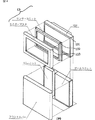
画像表示装置13は、プラズマディスプレイ装置で構成された表示部を含む。図4に、画像表示装置13の具体的な構造が模式的に示されている。画像表示装置13の最背面にプラズマディスプレイ装置131、その前面に入力装置であるタッチセンサ132、その前面にモニターマスク133、さらにその前面にフロントカバー134が設けられる。
図1で説明されるように、プラズマディスプレイ装置(PDP)は奥行きの寸法がCRT装置より小さくて済み、タッチセンサで構成された入力装置11もプラズマディスプレイ装置131の面に沿って収められているので、壁に掛けることもでき、42インチ程度の大画面でも少ないスペースに設置可能である。また、図2で説明されるように、プラズマディスプレイ装置(PDP)のように画面が湾曲しない平面で構成される画像表示装置は、湾曲しているCRT等の表示装置に比べ、正面から見た時の画像の歪みが少ない。また、特に本実施形態は魚の泳いでいる様子を表示する観賞遊戯装置であるので、大画面化により、大きな魚が大きな水槽内を泳ぐ様子も表示することができる。
処理装置10は、CPU(中央演算処理装置)101を有するとともに、ROM102、RAM103、サウンド装置104、入出力インターフェース106、スクロールデータ演算装置107、コ・プロセッサ(補助演算処理装置)108、地形データROM109、ジオメタライザ110、形状データROM111、描画装置112、テクスチャデータROM113、テクスチャマップRAM114、フレームバッファ115、画像合成装置116、D/A変換器117、CD−ROMドライブ118を備えている。
CPU101は、バスラインを介して所定のプログラムなどを記憶したROM102、データを記憶するRAM103、サウンド装置104、入出力インターフェース106、スクロールデータ演算装置107、コ・プロセッサ108、ジオメタライザ110、CD−ROMに記録された情報を読み取る為のCD−ROMドライブ118に接続されている。RAM103はバッファ用として機能させるもので、ジオメタライザ110に対する各種コマンドの書込み(オブジェクトの表示など)、変換マトリクス演算時のマトリクス書込みなどが行われる。
入出力インターフェース106は前記入力装置11及び出力装置12に接続されており、これにより入力装置11の操作信号がCPU101に取り込まれるとともに、CPU101などで生成された信号を出力装置12に出力できる。
サウンド装置104は電力増幅器105を介してスピーカ14に接続されており、サウンド装置104で生成された音響信号が電力増幅の後、音声出力装置としてのスピーカ14に与えられる。
CPU101は本実施例では、ROM102に内蔵したプログラムに基づいて入力装置11からの操作信号及び地形データROM109からの地形データ、又は形状データROM111からの形状データ(魚、海底地形等の3次元データ)を読み込んで、魚と海底地形との当たり(衝突)判定などの、魚の挙動計算(シミュレーション)等を行うようになっている。
魚の挙動計算は、所定のプログラムに基づき仮想空間での魚の動きをシミュレートするもので、3次元空間での座標値が決定された後、この座標値を視野座標系に変換するための変換マトリクスと、形状データ(魚、地形など)とがジオメタライザ110に指定される。コ・プロセッサ108には地形データROM109が接続され、したがって、予め定めた地形データがコ・プロセッサ108(及びCPU101)に渡される。コ・プロセッサ108は、主として、魚と地形との当たりの判定を行うものであり、そして、この判定や魚の挙動計算時に、主に、浮動小数点の演算を引き受けるようになっている。この結果、コ・プロセッサ108により魚と地形との当たり(衝突)判定が実行されて、その判定結果がCPU101に与えられるようにされているから、CPUの計算負荷を低減して、この当たり判定がより迅速に実行される。
ジオメタライザ110は形状データROM111及び描画装置112に接続されている。形状データROM111には予めポリゴンの形状データ(各頂点から成る魚、地形、背景などの3次元データ)が記憶されており、この形状データがジオメタライザ110に渡される。ジオメタライザ110はCPU101から送られてくる変換マトリクスで指定された形状データを透視変換し、3次元仮想空間での座標系から視野座標系に変換したデータを得る。
描画装置112は変換した視野座標系の形状データにテクスチャを貼り付け、フレームバッファ115に出力する。このテクスチャの貼り付けを行うため、描画装置112はテクスチャデータROM113及びテクスチャマップRAM114に接続されるとともに、フレームバッファ115に接続されている。なお、ポリゴンデータとは、複数の頂点の集合からなるポリゴン(多角形:主として3角形又は4角形)の各頂点の相対ないしは絶対座標のデータ群をいう。前記地形データROM109には、魚と地形との当たり判定を実行する上で足りる、比較的粗く設定されたポリゴンのデータが格納されている。これに対して、形状データROM111には、魚、背景等の画面を構成する形状に関して、より緻密に設定されたポリゴンのデータが格納されている。
スクロールデータ演算装置107は文字などのスクロール画面のデータを演算するもので、この演算装置107と前記フレームバッファ115とが画像合成装置116及びD/A変換器117を介して表示装置13に至る。これにより、フレームバッファ115に一時記憶された魚、地形(背景)などのポリゴン画面(シミュレーション結果)と魚の情報などの文字情報のスクロール画面とが指定されたプライオリティにしたがって合成され、最終的なフレーム画像データが生成される。この画像データはD/A変換器117でアナロク信号に変換されて表示装置13に送られ、画像がリアルタイムに表示される。
なお、この実施形態ではCD−ROMドライブ118を備えているが、これに限らず、フレキシブルディスク、光磁気ディスクその他の記録媒体の読取り手段を備えることとしても良い。
▲2▼(視点位置及び視線方向決定処理の概要)
次に、処理装置10における処理の内容を説明する。図5は、本実施形態による遊戯装置に備えられた処理装置10が視点及び視線の設定処理を実行する手順を示すフローチャートである。
まず、処理装置10により、仮想3次元空間内を移動する複数の移動体をそれぞれ模した仮想モデルが形成される。これら複数の移動体は、この実施形態では仮想3次元空間内を遊泳する複数の魚である。移動体の3次元ポリゴンデータは、ROMに予め記録されており、プログラムによって、個々の魚について泳ぐ動作、エラを揺らす動作等がなされる。
処理装置10は、前記複数の移動体の中から、視点及び視線を定める基準となる1つの移動体を選択する(S11)。この移動体の選択も、プログラムに基いて行われる。なお、1つの移動体群が互いに同方向、同速度等のまとまった動きをするときは、当該又は1つのまとまった動きをする移動体群を、選択することとしても良い。
次に、処理装置10は、S11において選択された当該1つの移動体又は移動体群の「状態」を認識する(S12)。ここで移動体の「状態」とは、移動体の仮想3次元空間における位置、向き(移動体の前面(魚の頭部)が向いている方向)、移動方向、移動速度等をいう。この移動体の状態は、RAMに一時記録される。
更に、処理装置10は、前記1つの移動体又は移動体群の状態に基いて視点の位置を決定する(S13)。この視点の位置の決定方法は後に詳述するが、前記1つの移動体の状態に基いて視点位置を決定することによって、視点の位置を少なくとも1つの魚に対して適切な位置に保持し、少なくとも当該1つの魚を適切に表示可能にすることができる。
次に、処理装置10は、前記1つの移動体又は移動体群の状態に基いて視線の方向を決定する(S14)。視線の方向の決定方法についても、後述する。
処理装置10は、こうして決定された視点及び視線に基いて、前記視点から前記視線の方向を見た場合の映像を随時生成し、当該画像を画像表示装置13に表示させる。
次に、S11で移動体が選択されてからS14で視線が決定されるまでの時間と、1つの移動体又は移動体群から他の1つの移動体又は移動体群へ視点の決定基準を移行させるための所定時間とを比較し(S15)、まだ所定時間が経過していないときは、S12に戻って移動体の状態が再度認識され、新たに認識された状態に基いて、視点及び視線が更新される。所定時間が経過した場合は、図5のフローを一度終了し、最初の処理に戻ってS11の移動体選択処理を再度行ない、他の移動体の状態を基準に視点を設定するので、更に変化に富んだ画像を生成することができる。
以上説明したように、複数の移動体のうち1つの移動体又は移動体群の状態に基いて視点の位置及び視線の方向を決定するので、視点及び視線を少なくとも当該1つの移動体又は移動体群に対して適切なものとすることができる。
▲3▼(視点の位置の算出処理)
上記S12において1つの移動体又は移動体群の「状態」を認識した後、S13において視点の位置を決定する処理について詳述する。図6はこの視点位置決定処理を実行する手順を示すフローチャート、図7及び図8は、視点位置の決定方法を、移動体が動く座標系に即して説明した説明図である。なお、簡単のため移動体の移動可能範囲の中心点に仮想3次元空間における座標系の原点を置く。
この座標系において、視点の位置は略Z軸の負方向の位置に設定されるが、以下に示すような計算により、例えば前記1つの移動体の向きが前記視点から遠ざかる方向となった場合には前記1つの移動体に近い位置に視点が設定され、前記1つの移動体の向きが前記視点に近づく方向となった場合には前記1つの移動体から遠い位置に視点が設定される等のバリエーションが与えられる。
まず、処理装置10は、図5のS12で認識された1つの移動体又は移動体群の方向(ベクトルVfとする)に基いて、所定の基準方向V’fを決定する(S21)。この所定の基準方向は、後述のように視点を揺らす処理を行なうために、移動体の方向Vfに基いて種々の方向に微少回転させることによって得られるが、Vfと同一の値でも良い。
次に、処理装置10は、図5のS12で認識された上記移動体の位置(Pfとする)、上記所定の基準方向V’f、視点位置を定めるために予め設定される基準距離Lfに基き、以下の計算を行なって所定の基準位置Bを算出する(S22)(図7参照)。
B.x=−V’f.x×Lf+Pf.x ・・・式(1x)
B.y= V’f.y×Lf−Pf.y ・・・式(1y)
B.z= V’f.z×Lf+Pf.z ・・・式(1z)
所定の基準位置Bは、上記1つの移動体又は移動体群の位置Pfから上記所定の基準方向V’fに向かって上記基準距離Lfだけ離れた位置(Bfとする)と比較すると分かり易い。位置Bfは、下記の式により求められる。
Bf.x=V’f.x×Lf+Pf.x ・・・式(1’x)
Bf.y=V’f.y×Lf+Pf.y ・・・式(1’y)
Bf.z=V’f.z×Lf+Pf.z ・・・式(1’z)
上記式(1z)及び式(1’z)から明らかなように、所定の基準位置BのZ座標B.zは、上記位置BfのZ座標Bf.zと同一である。従って、所定の基準位置Bは、位置Bfを含みZ軸に垂直な平面と、同一の面上にある。
従って、上記移動体の向きVf(≒V’f)がZ軸の正の方向(視点から遠ざかる方向)になると上記所定の基準位置BはZ軸の正の方向に移動し、視点もZ軸の正の方向に移動する(移動体に近づく)。逆に、上記移動体の向きVfがZ軸の負の方向(視点に近づく方向)になると上記所定の基準位置BはZ軸の負の方向に移動し、視点もZ軸の負の方向に移動する(移動体から遠ざかる)。
所定の基準位置Bや視点の位置がZ軸の正の方向又は負の方向にどの程度ずれるかは、上記式(1z)からも明らかなように、基準距離Lfの大きさに依存する(比例する)。基準距離Lfの大きさは、この実施形態では選択された移動体の大きさに依存した大きさに、予め設定される。
なお、上記式(1x)に示すように、所定の基準位置BのX座標B.xについては、移動体の位置Pfを含みYZ平面に平行な面について対称に、上記位置Bfを反転させた位置となる。これにより、視点位置の動きを移動体の動きに依存させつつ、適度な変化を与え、観察者が飽きないようにしている。
また、上記式(1y)に示すように、所定の基準位置BのY座標B.yについても、位置BfのY座標を求める式(1’y)と比べると、移動体の位置PfのY座標Pf.yの符号を反転させることにより、変化を与えている。特にこの実施形態では、複数の移動体は魚の群れであるので、水平方向(X軸又はZ軸方向)に比べ、上下方向(Y軸方向)の向きの変化が少ないので、式(1y)においてV’f.yの符号を反転させても視点の位置の変化に対する影響が少ない。そこで、式(1y)ではPf.yの符号を反転させている。
次に、処理装置10は、上記所定の基準位置BよりZ軸の負方向に所定距離Ls離れた位置B’を算出する(S23)(図8参照)。すなわち、
B’.x=B.x ・・・・・・・・・・・式(2x)
B’.y=B.y ・・・・・・・・・・・式(2y)
B’.z=B.z−Ls ・・・・・・・・式(2z)
ただし、この位置B’に視点を置いた場合、例えば基準となる移動体がZ軸の正方向に向かって移動可能範囲の限界まで移動すると、視点もそれにつれてZ軸の正方向に移動する。すると、視点が複数の移動体の移動可能範囲に入り過ぎてしまい、視点が基準となる移動体以外の他の移動体にぶつかってしまったり、他の移動体が極端に大きく表示されて見るに堪えない映像となるおそれがある。そこで、視点が移動体の移動範囲に入り過ぎないように、予め決められた範囲に収まるように、位置B’を更にZ軸の負の方向に下げる等の補正を行ない、視点の目標位置Pcを算出する(S24)。
以上のように、移動体の位置及び方向を考慮して視点の位置を決定するので、移動体と視点との距離が適正に保たれる。また、魚の泳いでいる深さが変化したり、魚の向きが上下方向に変化すれば、カメラの位置も上下方向に変化し、変化に富み遊戯者を飽きさせない画像を生成することができる。
(視線の方向の算出処理)
次に、上記図5のS14において注視点の位置を決定し、視線の方向を算出する処理について説明する。まず、注視点の位置を移動体の位置Pfとした場合、移動体の進行方向に対しての画像が得られにくく、見栄えが悪い画像となるおそれがある。そこで、移動体の現在の位置(最新の位置)と、移動体の過去の所定時間前(nフレーム前)の位置をもとに、移動体の将来の予想位置P’fを算出して注視点の目標位置とする。
移動体の1フレーム先の予想位置P’fは、移動体の最新(直前)フレームにおける位置をK0、更に1フレーム前の位置をK−1、2フレーム前の位置をK−2、...、nフレーム前の位置をK−nとすると、
P’f.x=K0.x
+{(K0.x−K−1.x)
+(K−1.x−K−2.x)
+・・・
+(K−(n−1).x−K−n.x)}÷n
=K0.x+(K0.x−K−n.x)÷n
・・・式(4x)
Y座標、Z座標についても同様に、
P’f.y=K0.y+(K0.y−K−n.y)÷n
・・・式(4y)
P’f.z=K0.z+(K0.z−K−n.z)÷n
・・・式(4z)
これに基き、上記視点の目標位置Pcから注視点の目標位置P’fに向かう視線のベクトル(目標値)V’cは、以下の式により求められる。
V’c.x=P’f.x−Pc.x ・・・・・・式(5x)
V’c.y=P’f.y−Pc.y ・・・・・・式(5y)
V’c.z=P’f.z−Pc.z ・・・・・・式(5z)
これにより、移動体が移動しているときに移動方向前方に視線を向けることができ、移動体をより見易く表示することができる。
(視点及び視線の動きの変化を緩やかにする処理)
上記で求めた視点の目標位置Pcに視点を置き、毎フレーム更新した場合、視点の位置は移動体の動きに応じて変化する。特に移動体の向きが急激に大きく変化した時は、視点の位置が急激に大きく変化し、見るに堪えない映像となるおそれがある。そこで以下のように、視点の目標位置Pcを、直前のフレームにおける視点の位置Ppに、毎フレーム数%ずつ重みをつけて更新し、視点位置Pnを導く。
Pn.x=R×Pc.x+(1−R)×Pp.x ・・・式(6x)
Pn.y=R×Pc.y+(1−R)×Pp.y ・・・式(6y)
Pn.z=R×Pc.z+(1−R)×Pp.z ・・・式(6z)
ここでRは、上記重みである。この計算により、直前に設定された視点の位置(Pp)と、一定時間後に新たに算出された視点の目標位置(Pc)とを結ぶ線分を所定の割合(1−R対R)で分ける位置(Pn)を算出する。こうして、魚が急激に位置や向きを変えても、カメラの位置の変化が遅れているので、カメラの位置に極端に急激で大きな変化がなく、見易く緩やかな動きになる。この実施形態では水中を泳ぐ魚を基準に視点を設定しているので、水中をカメラが漂っているような映像になる。
視線のベクトルについても、以下のように、視線のベクトルの目標値V’cを、直前のフレームにおける視線のベクトルVpに、毎フレーム数%ずつ重みをつけて更新し、視線のベクトルVnを導く。
Vn.x=S×V’c.x+(1−S)×Vp.x ・・・式(7x)
Vn.y=S×V’c.y+(1−S)×Vp.y ・・・式(7y)
Vn.z=S×V’c.z+(1−S)×Vp.z ・・・式(7z)
ここでSは、上記重みである。この計算により、視線の方向の変化は魚の位置や向きの変化より遅れるので、視線の方向に極端に急激で大きな変化がなくなるため、見易く、緩やかな動きになる。
▲4▼(視点を揺らす処理)
次に、上記図6のS21において、上記移動体の方向Vfに基いて、所定の基準方向V’fを決定する処理を説明する。この処理では、視点を揺らす処理を行なうために、移動体の方向Vfに基いて種々の方向に微少回転させる。
移動体の方向のベクトルVfの大きさを変えずに微少回転させるnパターンの変換行列をG1、G2、...、Gnとし、上記基準距離Lfに比べ非常に小さい値をLgとする。各パターンで得られるオフセットベクトルS1、S2、...、Snは、
S1=Lg・Vf・G1
S2=Lg・Vf・G2
・・・
Sn=Lg・Vf・Gn ・・・・・・式(8)
これらS1、S2、...、Snを、式(1x)〜(1z)のベクトルVfと無作為に入れ替え、視点の位置を算出する。これにより、式(2)、式(5)、式(6)、式(7)等の動作に大筋では従いつつ、視点位置を所定の微少範囲内で更に揺らすように動かすことができる。
また、移動体の動きに基いて視点の基準値を算出し、当該視点基準値を中心とする所定の範囲内で前記視点を動かすことによっても、視点を揺らす動きを実現することができる。
これにより、移動体の動きが少ない場合でも、視点は複数の点を辿るように動き、いろいろな位置から移動体を見た画像を表示することができ、表示のバリエーションが更に増える。
▲5▼(明瞭化処理)
本実施形態の観賞遊戯装置20においては、所定モードの時、遊戯者が画面に触れると、画面上の触れた部分及びその周りの部分だけを触れる前より明るくし、画像を明瞭化する処理がなされる(図9参照)。図10は、その処理を実行する手順を示すフローチャートである。
まず、処理装置10は、入力装置であるタッチセンサ132に入力があったかどうか、および、入力のあった場所が画像表示装置上のどの位置であるかを判断する(S31)。
次いで、処理装置10は、画面上の入力のあった場所が所定の輝度より暗いか否かを判断する(S32)。所定の輝度より暗い時は次のステップに進むが、所定の輝度以上の輝度があり画面が明るい時は、この明瞭化処理を行なわない。
次に、処理装置10は、画面上の入力のあった場所に対応する仮想3次元空間における点及びその周辺について明瞭化処理を行なう(S33)。具体的には、複数の移動体を模した仮想モデルを2次元投影するための視点から、前記入力のあった場所およびその周辺の一定範囲に向けて仮想の光(ここではスポットライト光源による)をあて、仮想モデルにおける光の反射をシミュレートして、仮想モデルに光の当たった状態の画像を生成する。こうして光を当てることにより、輝度ないし明度が上昇し、コントラストも明瞭になるので、暗くて良く見えなかった魚等も良く見えるようになる(図9参照)。なお、光源から仮想モデルまでの距離による光の減衰も考慮してシミュレートするので、対象画素に仮想モデルが存在しない場合は照らす作用は働かず、光源からの距離が大きい部分はあまり明るくならないので、リアリティに富んだ明瞭化表現ができる。なお、光源の位置と視点の位置とが同一であるため、仮想モデルによる影は形成されない。
次に、処理装置10は、当該入力のあった位置について明瞭化処理が開始されてから所定の微少時間が経過したことを判断すると(S34)、当該部分の明瞭化処理を終了する(S35)。従って、遊戯者が画面を撫でるように触れる位置をずらしながら触れた場合は、それにつれて明瞭化処理の行われる部分も移動し、サーチライトのように、照らす位置が次第に移動していくような画像が生成される。
なお、明瞭化処理により移動体の動きにも影響を与え、光の照らされた部分に魚が寄ってくるという演出をしても良い。
このように、本実施形態では画面上の任意の場所に手で触れるだけで、明瞭化の場所を指定することができる。簡便な操作により遊戯することを可能にしている。
▲6▼(情報出力処理)
この実施形態による観賞遊戯装置20は、所定モードにおいて遊戯者が画像表示装置13に表示されている移動体(魚)の表示部分に触れると、その移動体のデータが当該画像表示装置の一部に表示され、動物図鑑のように利用して楽しむことができる(図11参照)。
図12は、この情報出力処理を実行する手順を示したフローチャートである。まず、処理装置10は、入力装置であるタッチセンサ132に入力があったか否か、および入力があった場合にはその入力に対応する画面上の位置を判定する(S41)。
次に、処理装置10は、入力があった位置に表示されている表示対象物が何であるかを判断する(S42)。そして、当該判断に基づき、予めROMに記録されている当該表示対象についての情報を、画像表示装置13の表示部に出力する(S43)(図11参照)。この場合、情報を表示するときは、情報の表示部分によって、対応する表示対象物を覆わないように(好ましくは、重なる部分がないように)、情報を表示部の端部付近に表示する。
同一の表示対象につき入力手段への入力が続いている場合は情報の表示を継続させ、入力が終了したり、別の表示対象に入力の対象が移動した場合は、当該表示対象についての情報の表示を終了する。
▲7▼(第2実施形態の構成)
次に、本発明の第2実施形態に係る画像表示装置、画像表示システム、画像処理装置ないし観賞遊戯装置について説明する。この実施形態の基本構成は、図3に示した第1実施形態の基本構成とほぼ同様であるが、画像表示装置13が、以下の点で第1実施形態における画像表示装置と異なっている。
第2実施形態における画像表示装置13の表示部は、ブラウン管135で構成されている。図13は第2実施形態の遊戯装置21の外観を示す正面図であり、図14はそのA−A線断面図である。これらの図に示すように、ブラウン管135の前面には、タッチセンサを備えた透明のフロントカバー136、枠部材137が備えられている。
枠部材137は、潜水艦の窓の形状を模したものであり、枠部材137の前面からフロントカバー136までは約5cm、ブラウン管135までは約10cmの厚みがある。
ブラウン管135には、仮想の窓を通して窓の向こう側を見た場合の観賞用画像が表示される。上記のように表示部の前面に当該仮想の窓に相当する形状を備えた枠部材を取り付け、厚みもつけたので、実際に窓から窓の向こう側を覗いているかのような印象を観察者に与える。特にこの実施形態では、当該仮想の窓は潜水艦の窓であり、前記観賞用画像は水中の様子を潜水艦の中から見た映像(水中を泳ぎまわる魚など)であるため、観賞用画像にリアリティを持たせる効果がある。
▲8▼(描画処理)
次に第2実施形態による画像処理の手順について説明する。この実施形態による観賞遊戯装置21では、入力がない状態では移動体である多数の小魚が水中を泳ぎまわっている様子が画像表示装置13に表示されているが、遊戯者が画面上を指でなぞると(図15(a))、これら多数の小魚が、なぞった軌跡上の所定の場所に泳いで行って整列し、これら多数の小魚全体で、遊戯者がなぞった通りの線図(文字、図形その他の形状)を描くことができる(図15(b))。図16は、この描画処理により小魚の配列を実行する手順を示すフローチャートであり、図17は、その処理の内容の説明図である。
処理装置10は、入力がない状態では、多数の小魚が水中を泳ぎまわっている様子を画像表示装置13に表示している(S51)。入力手段であるタッチセンサに入力があると(S52)、処理装置10は、その入力の内容を所定時間(この実施形態では2秒間)にわたって認識し、一定の微少時間ごと(この実施形態では1インタラプトすなわち60分の1秒ごと)の、入力に対応する表示面上の位置を、記録手段に記録させる(S53)。この実施形態では、2秒間にわたる入力対応位置を60分の1ごとに記録するので、120箇所の入力対応位置が記録される。上記の入力可能な所定時間経過後に入力があっても、その入力(図17の120番目以降の時間に対応する入力)は認識されない。
入力が中断された場合には(例えば図17のM番目の時間に対応する入力がされた時に入力が中断された場合には)、一定時間を限度として入力が再開されるまで待つ。入力再開が可能な上記一定時間内に入力が再開された場合には、入力中断時から再開時までの時間だけ、上記所定時間を延長する(図17のM+1番目から120番目までの時間に対応する位置をMに続けて記録する)。なお、上記の入力可能な所定時間内は、入力認識及び記録が可能であることを遊戯者に示すために、音又は音楽を鳴らすようにしても良い。
入力再開が可能な上記一定時間内に入力が再開されなかった場合、認識された入力箇所が120箇所に満たない場合でも、入力の認識及び記録を途中で終了し、それまでに記録された位置にのみ前記各微少時間に対応する移動体を配置する。入力されなかった時間に対応する前記移動体は、表示部の端部に配置されるか、表示部の端部から表示部の外側へ出て行く。
次に、処理装置10は、上記で入力された各時間ごとの位置に、複数の移動体(小魚)を各位置に一定の数ずつ(この実施形態では1つずつ)配置する(S54)。複数の移動体のそれぞれには、上記入力の各時間のうちどの時間の入力位置に対応するかが予め決められており、各移動体が、それぞれ予め決められた時間の入力に対応する位置に配置される。例えば図17に示すように、時間Nに対応する入力位置には、番号Nの魚が配置され、時間N+1に対応する入力位置には、番号N+1の魚が配置される。配置された後は各移動体の位置は移動しないが、位置を動かさずに所定の動作をさせてもよい。この実施形態では複数の移動体は複数の小魚であり、配置された後は尾びれを振る様子を表示する。
処理装置10は、複数の移動体(小魚)を所定の位置に配置する場合、個々の移動体同士が衝突しているか(重なっているか)否かを随時判定し、衝突している場合には、これら移動体を互いに少し引き離す処理を行なう。これにより、移動体が他の移動体の陰に隠れることを防止している。
移動体をS54で配置させた後、一定時間が経過すると(S55)、移動体の配置が解除され(S56)、S51に戻って、次の入力がない限り多数の移動体(小魚)が水中を自由に泳ぎまわる様子が表示される。
以上の処理により、遊戯者は画面をなぞることによって、それまで画面上を動きまわっていた移動体がなぞった通りの配列に並べることができ、従来の画像表示システムにない新たな表現方法を楽しむことができる。また、この実施形態では、表示面をなぞる速さに伴って移動体に粗密ができ、多様な表現が可能である。
▲9▼(所定位置配列処理)
本実施形態の観賞遊戯装置21では、入力装置11に対する入力が一定時間なされない時、一定時間ごとに、前記複数の移動体が予め記録された通りの配列をするように構成されている(図18)。
図16のフローチャートのS52において、処理装置10が、入力のない状態が一定時間続いていると判断した場合、図18(a)のようにランダムに動きまわっていた複数の移動体を、例えば図18(b)のように、ROMに予め記録されている線図(文字、図形等)の通りに配置させて画像表示装置13に表示させる(S57)。更に一定時間が経過すると(S52)、例えば図18(c)又は(d)のように、予め記録されている別の配置の通りに、複数の移動体を並べて表示させる。入力手段に入力があった場合には、S53に移行して入力された通りの配置を行なう。
以上により、複数の移動体を表示する観賞遊戯装置において、所定の場合に移動体を整列させて所定の線図を描くことができ、新たな遊戯性を付加することができる。
また、本実施形態の観賞遊戯装置21に別の遊戯モードを設け、遊戯者が指でなぞった通りに配列させた移動体の配置をRAM等の記録装置に記録させ、一定時間後に再度その配列を再現させることを可能とすることもできる。この場合、遊戯者が他の遊戯者に対する伝言用の文字を表示面上に描いて記録装置に記録させ、これを一定時間後(例えば1時間後)にその配列を再現させるようにすれば、遊戯者がこの観賞遊戯装置を伝言板のように使用することもできる。
なお、この第2実施形態では、複数の移動体として多数の小魚を表示することとしたが、これに限らず、昆虫、鳥、その他の動物等を表示することとしても良い。
産業上の利用可能性
本発明によれば、複数の移動体が動く様子を示す観賞用画像を生成する観賞遊戯装置等において、遊戯性の高い遊戯装置を提供することができ、より詳しくは以下の効果を有する。
第1に、前記1つの移動体又は移動体群の状態に基いて視点位置を決定することによって、視点の位置を少なくとも1つの魚に対して適切な位置に保持し、少なくとも当該1つの魚を適切に表示可能にすることにより、仮想空間上を動き回る移動体を、観察者の興味を減じないように適切に表示することができる画像処理装置を提供することができる。
第2に、移動体を確実に表示させるように視点及び視線を設定することにより、仮想空間上を動き回る移動体を、観察者の興味を減じないように適切に表示することができる画像処理装置を提供することができる。
第3に、画像に変化を持たせることにより、仮想空間上を動き回る移動体を、観察者の興味を減じないように適切に表示することができる画像処理装置を提供することができる。
第4に、画面上で所定の入力をするだけで、明るくする部分を選択できる画像表示システムを提供することができる。
第5に、本発明は、複数の魚その他の移動体を画像表示装置に表示させ、これを疑似ペットのように観賞する観賞遊戯装置において、これら複数の移動体のそれぞれについて容易に説明を表示させることができるようにすることにより、観賞をより楽しく分かり易いものにすることができる。
第6に、本発明は、現実性に富んだ画像を表示可能な観賞用画像表示装置を提供することができる。
第7に、画面をなぞった軌跡に従って描画された画像を表示する画像表示システムにおいて、新たな表現方法を提供することができる。また、観賞用画像表示システムにおいてなぞった軌跡に従って移動体を任意の配列に並べさせることを可能とし、遊戯性を付加することができる。
第8に、本発明は、複数の魚その他の移動体を画像表示装置に表示させ、これを疑似ペットのように観賞する観賞遊戯装置において、通常の状態では移動体に自然な動きをさせて観賞に堪えるようにするとともに、一定モードにおいては複数の移動体に所定の配置をさせ、全体で所定の線図(文字、図形等)を示すようにし、観賞の面白味を加えることができる。
第9に、設置スペースを小さくしつつ大画面化が可能な画像表示装置を提供することができる。また、大画面でかつ画像の歪みのない画像表示装置を提供することができる。
【図面の簡単な説明】
図1は、CRT装置とプラズマディスプレイ装置(PDP)の設置スペースを比較した説明図である。
図2は、CRT装置とプラズマディスプレイ装置(PDP)による画像の歪みを比較した説明図である。
図3は、本発明の観賞遊戯装置の基本構成を示すブロック図である。
図4は、第1実施形態による画像表示装置の具体的な構造を示す説明図である。
図5は、視点及び視線の設定処理を実行する手順を示すフローチャートである。
図6は、視点位置決定処理を実行する手順を示すフローチャートである。
図7は、視点位置の決定方法に関する説明図である。
図8は、視点位置の決定方法に関する説明図である。
図9は、明瞭化処理による画像を示した説明図である。
図10は、明瞭化処理を実行する手順を示すフローチャートである。
図11は、情報出力処理による画像を示した説明図である。
図12は、情報出力処理を実行する手順を示したフローチャートである。
図13は、第2実施形態の遊戯装置の外観を示す正面図である。
図14は、図13のA−A線断面図である。
図15は、描画処理による画像を示した説明図である。
図16は、描画処理を実行する手順を示すフローチャートである
図17は、描画処理の説明図である。
図18は、所定位置配列処理による画像を示す説明図である。
なお、図中、符号10は画像処理装置、11は入力装置、20は観賞遊戯装置、13は画像表示装置、131はプラズマディスプレイ装置、132はタッチセンサ、21は観賞遊戯装置、135はブラウン管、136はフロントカバー、137は枠部材である。Technical field
The present invention relates to an image display device, an image processing device, and an image display system.
Background art
{Circle around (1)} Conventionally, in the field of game devices equipped with an image display device, there is an amusement game device that displays a fish or other moving body on the image display device and views it like a pseudo pet. In the image processing device provided in this amusement game device, a virtual model imitating a moving body can be formed in a virtual three-dimensional space, and an image viewed from a predetermined viewpoint can be displayed on the display means.
However, if the viewpoint or gazing point is fixed, the background screen does not change, and the expression of the three-dimensional effect is insufficient. In addition, if the movement of the viewpoint or the gazing point becomes uniform, the change of the background screen becomes uniform, which may reduce the interest of the observer. On the other hand, if the viewpoint or gazing point is moved at random, the moving object may not enter the field of view, or the moving object may not enter the center of the field of view, which may reduce the interest of the observer.
(2) Furthermore, even when entering the field of view, if the distance between the viewpoint and the moving body is too long or too short, there is a risk of reducing the interest of the observer. In addition, it is possible to obtain a more easily viewable image by setting the viewpoint and the position of the gazing point in consideration of the direction in which the moving body is facing and the direction in which the moving body is moving. Furthermore, when the movement of the moving body changes abruptly, it is easier to see the image when the movement of the viewpoint or the gazing point is relaxed.
(3) Furthermore, when moving the viewpoint depending on the movement of the moving body, if the movement of the moving body is small, the movement of the viewpoint is also reduced, which may reduce the interest of the observer.
(4) Further, in an image display system that displays an image when a model in a virtual space is viewed from a predetermined viewpoint, there is an image display system that can display a state when virtual light is applied to the model. Are known.
However, there is no known device that can easily and freely set a brightened portion on the screen.
(5) Further, when the mouse pointer is moved to a predetermined part on the image displayed on the image display device and the mouse is clicked, an image display system for displaying an explanation about what is displayed on the predetermined part on the image Is known.
However, in an ornamental image display system that displays images of a plurality of fish and other animals and plants on an image display device and views them like a pseudo pet, there is no one that displays information on each moving object.
(6) Also, for example, when displaying an image of a submarine viewed through the window as an ornamental image on the image display device, the image of the window frame is displayed together with the image outside the window. It is conceivable to have reality.
However, even if the image of the window frame is displayed, the thickness of the window frame cannot be expressed, so that the image lacks realism and may be unsatisfactory as an ornamental image.
(7) There is also known a display system that includes an input means on the screen of the image display device and can draw a trace as traced by tracing the screen with an attached input pen or the like.
However, there is no conventional technique in which a plurality of moving bodies are arranged on a traced locus and drawing is performed using the plurality of moving bodies.
(8) In addition, a display system is known in which a graphic or character recorded in advance is displayed on a display device and can be updated to another graphic or character recorded in advance at regular intervals.
However, in an amusement game device in which a plurality of fish and other moving objects are displayed on an image display device and viewed as a pseudo pet, a diagram (characters, figures, etc.) is displayed by the arrangement of the plurality of moving objects. Things are not known.
{Circle over (9)} Conventionally, there are image display devices such as CRT and liquid crystal in the field of image display devices. However, since the CRT uses a cathode ray tube, it is necessary to increase the size of the depth (see FIG. 1) and to provide a large installation space, particularly when a large screen is provided. In addition, an image display device using liquid crystal is expensive, and the cost increases particularly when trying to make a large screen. If a joystick or various operation buttons are provided as an input device, a wider installation space is required. Furthermore, 36 inches is the limit in CRT, and a larger screen cannot be realized.
In addition, when the image display surface is curved as in a CRT, a portion of the image reflected on the end of the display surface appears distorted (see FIG. 2). In particular, when displaying an image by three-dimensional CG, there is a problem that distortion of the image impairs the expression of the stereoscopic effect. In addition, when viewed from a certain distance, the distortion at the edge of the image is reduced, but when viewed closer to the screen, the distortion of the image is large. In particular, when a touch sensor is provided on the screen to enhance the interactivity between the image observer and the screen, the image observer must approach the screen and see the image, and the image distortion cannot be ignored. It becomes.
Therefore, the present invention aims to provide a game device having high playability in an amusement game device or the like that generates an ornamental image showing a state in which a plurality of moving objects move, and more specifically, the following items are aimed at. .
First, by determining the viewpoint position based on the state of the one moving object or group of moving objects, the position of the viewpoint is maintained at an appropriate position with respect to at least one fish, and at least the one fish is It is an object of the present invention to provide an image processing apparatus capable of appropriately displaying a moving body that moves around in a virtual space so as not to reduce the interest of an observer by appropriately displaying.
Second, by setting the viewpoint and line of sight so that the moving object is displayed reliably, the moving object that moves around in the virtual space can be appropriately displayed so as not to reduce the interest of the observer. The purpose is to provide.
A third object of the present invention is to provide an image processing apparatus capable of appropriately displaying a moving body that moves around in a virtual space so as not to reduce the interest of an observer by giving a change to the image.
Fourthly, an object of the present invention is to provide an image display system capable of selecting a brightened portion only by performing predetermined input on a screen.
Fifth, the present invention displays a plurality of fish and other moving objects on an image display device, and displays an explanation of each of the plurality of moving objects in an amusement game device for viewing the same as a pseudo pet. The purpose is to make the appreciation more enjoyable and easy to understand.
Sixth, an object of the present invention is to provide an ornamental image display device capable of displaying a realistic image.
A seventh object of the present invention is to provide a new expression method in an image display system that displays an image drawn according to a locus traced on a screen. It is another object of the present invention to add playability by allowing moving objects to be arranged in an arbitrary arrangement according to a trace traced in an ornamental image display system.
Eighth, according to the present invention, in an amusement game device in which a plurality of fish and other moving objects are displayed on an image display device and viewed as a pseudo-pet, in a normal state, the moving object is caused to move naturally. In addition to being able to endure the appreciation, in a certain mode, a plurality of moving objects are arranged in a predetermined manner so as to show a predetermined diagram (characters, figures, etc.) as a whole, and the purpose of adding appreciation to the appreciation .
A ninth object is to provide an image display device capable of increasing the screen size while reducing the installation space. It is another object of the present invention to provide an image display apparatus having a large screen and no image distortion.
Disclosure of the invention
In order to achieve the above object, the present invention provides an image processing apparatus that displays on a display means an image when a plurality of moving bodies moving in a virtual three-dimensional space are viewed from a predetermined viewpoint. The position of the viewpoint is set based on the state of one moving body selected from the body or one moving body group that moves together.
Further, it is desirable to set the direction of the line of sight from the viewpoint based on the state of the one moving body or moving body group.
Further, it is desirable that the position of the viewpoint is switched from a reference based on the one moving body or moving body group to a reference position based on the other moving body or moving body group every predetermined time.
The image processing apparatus of the present invention includes a moving body model forming unit that forms a virtual model imitating each of a plurality of moving bodies moving in a virtual three-dimensional space, and one moving body or a moving body from the plurality of moving bodies. A moving body selecting means for selecting one moving body group that moves together, a state recognizing means for recognizing the state of the one moving body or the moving body group, and a state of the one moving body or the moving body group. A viewpoint position setting unit that sets a viewpoint position based on the viewpoint and a video generation unit that generates a video when all or some of the plurality of moving objects are viewed from the viewpoint are provided.
Further, the camera further includes a line-of-sight direction setting unit that sets a line-of-sight direction based on a state of the one moving body or the group of moving bodies, and the image generation unit displays an image when the direction of the line of sight is viewed from the viewpoint. It is desirable to generate.
The present invention is also an image processing apparatus for displaying on a display means an image when one or more moving bodies moving in a virtual three-dimensional space are viewed from a predetermined viewpoint, wherein the one or more movements are performed. The distance from the one moving body or the moving body group of the viewpoint set when the direction of one moving body or one moving body group that moves together is a direction away from the viewpoint is It is characterized in that the direction of one moving body or moving body group is shorter than the distance from the one moving body or moving body group of the viewpoint set when the direction approaches the viewpoint.
The image processing apparatus according to the present invention includes a moving body model forming unit that forms a virtual model imitating one or more moving bodies moving in a virtual three-dimensional space, and the one or more moving bodies. State recognition means for recognizing the state of one moving body or one group of moving bodies, and viewpoint position setting means for setting the position of the viewpoint based on the state of the one moving body or moving body group; An image processing unit that generates a video when viewing all or part of the plurality of moving objects from the viewpoint, wherein the state recognition unit is the one moving object or moving object Recognizing the position (Pf) and direction (Vf) of the body group, the viewpoint position setting means sets the viewpoint position (Pn) based on the position and direction of the one moving body or the moving body group. Features.
The viewpoint position setting means calculates a predetermined reference direction (V′f) based on the direction (Vf) of the one moving body or moving body group, and the position of the one moving body or moving body group. A position (B ′) that is a predetermined distance (Ls) away from a plane including a position (Bf) that is a predetermined distance (Lf) away from (Pf) toward the predetermined reference direction (V′f) is calculated. It is desirable to set the viewpoint position (Pn) based on this.
The present invention is also an image processing apparatus for displaying on a display means an image when one or more moving bodies moving in a virtual three-dimensional space are viewed from a predetermined viewpoint, wherein the one or more movements are performed. The position of the viewpoint is set based on the state of one moving body or one group of moving bodies that move together, and the line of sight from the viewpoint is based on the state of the one moving body or the moving body group. The direction of the line of sight is directed to a position in front of the moving direction of the one moving body or moving body group when the one moving body or moving body group is moving. To do.
The image processing apparatus according to the present invention includes a moving body model forming unit that forms a virtual model imitating one or more moving bodies moving in a virtual three-dimensional space, and the one or more moving bodies. State recognition means for recognizing the state of one moving body or one group of moving bodies, and viewpoint position setting means for setting the position of the viewpoint based on the state of the one moving body or moving body group; , A line-of-sight direction setting means for setting a line-of-sight direction based on the state of the one moving body or group of moving bodies, and an image for generating an image when all or some of the plurality of moving bodies are viewed from the viewpoint An image processing apparatus including a generation unit, wherein the video generation unit generates a video when the direction of the line of sight is viewed from the viewpoint, and the state recognition unit is the one moving body or the moving body. Group position (Pf) and orientation ( f) recognizes, the sight line direction setting means, the current position of the one mobile or mobile group recognized by the state recognition means (K0) And a position in the past predetermined time (Kn), The direction of the line of sight is set.
The line-of-sight direction setting means may be configured to detect a current position (K) of the one moving object or moving object group recognized by the state recognition means0) And a position in the past predetermined time (Kn) Based on the previous position (Kn) To the current position (K0It is desirable to set the direction of the line of sight so that the gazing point is placed at a predetermined position on the extended line of the straight line toward
The present invention is also an image processing apparatus for displaying on a display means an image when one or more moving bodies moving in a virtual three-dimensional space are viewed from a predetermined viewpoint, wherein the one or more movements are performed. The position of the viewpoint is set based on the state of one moving body selected from the body or one moving body group that moves together, and the movement of the viewpoint is determined by the one moving body or the moving body group. It is characterized in that it changes with a delay with respect to the change of movement.
The present invention is also an image processing apparatus for displaying on a display means an image when one or more moving bodies moving in a virtual three-dimensional space are viewed from a predetermined viewpoint, wherein the one or more movements are performed. The position of the viewpoint is set based on the state of one moving body selected from the body or one moving body group that moves together, and based on the state of the one moving body or moving body group The direction of the line of sight from the viewpoint is set, and the movement in the direction of the line of sight changes with a delay with respect to the movement of the one moving body or the moving body group.
The present invention is also an image processing apparatus for displaying on a display means an image when one or more moving bodies moving in a virtual three-dimensional space are viewed from a predetermined viewpoint, wherein the one or more movements are performed. Viewpoint target position calculation means for calculating the target position (Pc) of the viewpoint based on the state of one moving body or one group of moving bodies in the body, and the calculation result of the viewpoint target position calculation means Viewpoint position setting means for setting the viewpoint position based on the viewpoint position setting means, and the viewpoint position setting means newly calculates the viewpoint position (Pp) set immediately before and the viewpoint target position calculation means after a certain time. A position (Pn) that divides a line segment that connects the target position (Pc) of the viewpoint is calculated at a predetermined ratio, and a new viewpoint position is set.
The present invention is also an image processing apparatus for displaying on a display means an image when one or more moving bodies moving in a virtual three-dimensional space are viewed from a predetermined viewpoint, wherein the one or more movements are performed. Viewpoint position setting means for setting the position of the viewpoint based on the state of one moving body or one group of moving bodies that move together, and the state of the one moving body or moving body group A line-of-sight target value calculation unit that calculates a target value of the line-of-sight direction from the viewpoint, and a line-of-sight direction setting unit that sets a line-of-sight direction based on a calculation result of the line-of-sight direction target value calculation unit, The direction setting means has a predetermined ratio between the gaze direction (Vp) set immediately before and the gaze direction target value (V′c) newly calculated after a predetermined time by the gaze direction target value calculation means. Calculate the direction (Vn) divided by And sets as the direction of the line of sight.
The present invention is also an image processing apparatus for displaying on a display means an image when one or more moving bodies moving in a virtual three-dimensional space are viewed from a predetermined viewpoint, wherein the one or more movements are performed. A viewpoint reference value calculating means for calculating a reference value of a viewpoint based on a state of one moving body or one group of moving bodies in the body, and the viewpoint calculated by the viewpoint reference value calculating means The viewpoint is moved within a predetermined range centered on a reference value.
Further, it is desirable to set the viewpoint by calculating the viewpoint and setting it as a reference value for the viewpoint, and further moving the viewpoint within a predetermined range.
Further, the viewpoint position setting means is based on a vector obtained by multiplying a vector (Vf) of the direction of the one moving body or moving body group by a predetermined transformation matrix (Gt) for rotating the vector by a predetermined angle. It is desirable to set the predetermined reference direction (V′f).
The predetermined transformation matrix (Gt) is a plurality of transformation matrices (G1Thru Gn) Are randomly selected from the plurality of transformation matrices (G1Thru GnIt is desirable to replace it with another matrix selected at random.
The present invention also provides an image display device, input means capable of inputting corresponding to each point on the display surface of the image display device, and displaying an image on the image display device and processing an input signal from the input means. An image display system comprising a processing device, wherein when an input is made to the input means, an image around a point on the display surface corresponding to the input is clarified as compared to before the input. .
The image displayed on the image display device is an image when a virtual model formed on the virtual three-dimensional space is viewed from a predetermined viewpoint, and corresponds to the input from one point on the virtual three-dimensional space. It is desirable to irradiate virtual light toward a point on the virtual three-dimensional space displayed at a point on the display surface and its periphery.
Further, the image processing apparatus of the present invention determines that there is an input to an input means capable of inputting corresponding to each point on the display surface of the image display device, and on the display surface corresponding to the input. An input determining means for determining a position; and a clarifying means for clarifying the image on the display screen corresponding to the input and the image in the vicinity thereof according to the determination result by the input determining means as compared to before input. Features.
In addition, it is preferable to further include a luminance determining unit that determines that the image output to the image display device is equal to or lower than a predetermined luminance, and to make the clarifying unit function according to the determination result of the luminance determining unit.
The image to be displayed on the image display device is an image obtained by viewing a virtual model formed on the virtual three-dimensional space from a predetermined viewpoint, and the clarification unit is configured to display the virtual model from one point on the virtual three-dimensional space. It is desirable to irradiate virtual light toward a point on the display screen corresponding to the input and its periphery.
In addition, the image processing apparatus of the present invention operates (instructs) a planar display unit that displays a model arranged in a virtual three-dimensional space as an image captured from a predetermined viewpoint, and a display screen of the display unit. And an image detecting unit for increasing the brightness of a point on the display screen corresponding to the position detected by the instruction detecting unit or a peripheral area thereof.
The image processing apparatus of the present invention includes a planar display unit that displays a model arranged in a virtual three-dimensional space as an image captured from a predetermined viewpoint, and a position operated with respect to the display screen of the display unit And a video control means for increasing the brightness of the color of the image of the point on the display screen corresponding to the position detected by the instruction detection means or the peripheral area thereof.
The present invention also provides an image display device, input means capable of inputting corresponding to each point on the display surface of the image display device, displaying an ornamental image on the image display device, and an input signal from the input means. An image display system for processing an image, wherein when there is an input to the input means, information relating to a display object displayed at a position on the display surface corresponding to the input is displayed on the image display device It is an ornamental image display system characterized by being displayed on the screen.
The input means is preferably a touch sensor provided along a display surface of the image display device.
Further, the present invention is an ornamental image display device including a display unit that displays an ornamental image when the other side of the window is viewed through a virtual window, which corresponds to the virtual window on the front of the display unit An ornamental image display device characterized in that a frame member having a shape is provided.
Moreover, it is desirable that the ornamental image is an image imitating a state of seeing the underwater state.
The present invention also provides an image display device, input means corresponding to each point on the display surface of the image display device, and displaying an image of a plurality of moving bodies on the image display device and processing input signals from the input means. An image display, wherein when there is an input to the input means, all or a part of the plurality of moving bodies are arranged along a locus of points on the display surface corresponding to the input System.
Further, a predetermined number of positions on the display surface for each predetermined time input by the input means are recorded, and the plurality of moving bodies are recorded for each of the recorded positions on the display surface for each predetermined time. It is desirable to arrange a certain number of them.
In addition, a certain number of the plurality of moving bodies are assigned in correspondence with each predetermined time, and a certain number corresponding to each predetermined time is assigned to each position on the display surface for each predetermined time. It is desirable to arrange a movable body.
Further, it is desirable that the plurality of moving bodies are arranged so as not to overlap each other.
The input means is preferably a touch sensor provided on a display surface.
The images of the plurality of moving bodies are ornamental images for displaying a plurality of animals. If there is no input to the input means, the plurality of animals move around but are displayed on the image display device. If there is, it is desirable to place the plurality of animals at predetermined positions along the locus of points on the display surface corresponding to the input.
In addition, the present invention provides a predetermined number of inputs to an image output unit that outputs an image including a plurality of moving bodies to an image display device, and an input device capable of input corresponding to each point on the display surface of the image display device. An image processing apparatus comprising: an input recognizing unit that recognizes; and a moving body arranging unit that arranges a moving body at a position on the display surface corresponding to the recognized input.
The input recognizing means recognizes the input every predetermined time over the predetermined number, and the moving body arranging means is located at a position on the display surface corresponding to each input recognized every predetermined time. It is desirable to arrange a certain number of moving bodies.
Further, the moving body arranging means determines whether or not a plurality of moving bodies overlap each other on the display surface, and changes the position of the moving body so that the display of the moving bodies does not overlap according to the determination result. desirable.
Further, the present invention is an ornamental image display system comprising an image display device and a processing device that generates an ornamental image representing a state in which a plurality of moving bodies move and displays the image on the image display device. In this case, the mobile game apparatus is characterized in that each of the moving bodies is arranged at a predetermined position recorded in advance, and a predetermined diagram is drawn as the whole of the plurality of moving bodies.
The present invention also provides an ornamental image generating means for generating an ornamental image representing a state in which a plurality of moving bodies move and displaying the image on the image display device, and a predetermined time has elapsed since the start of the ornamental image generation process. A time determining means for determining that, and a predetermined position for arranging each of the moving bodies at a predetermined position recorded in advance based on a determination result of the time determining means and drawing a predetermined diagram as the whole of the plurality of moving bodies. An image processing apparatus comprising an arrangement unit.
The present invention also provides a planar display unit that displays a model arranged in a virtual three-dimensional space as an image captured from a predetermined viewpoint, and a position operated (instructed) on the display screen of the display unit. An image processing apparatus comprising: an instruction detection unit for detecting; and an image control unit for changing the image according to a position detected by the instruction detection unit, wherein the display unit is configured by a plasma display device. is there.
Further, it is desirable that the video control means changes the display state of the display body displayed at a position corresponding to the position operated on the display screen.
In addition, it is preferable that the instruction detection unit is provided along a display surface of the display unit.
Further, the present invention is a medium recording a program for causing a processing device to execute each of the above means.
Note that the recording medium is a medium in which information (mainly digital data, a program) is recorded by some physical means, and allows a processing device such as a computer or a dedicated processor to perform a predetermined function. It can be done. Any program that downloads a program to a computer and executes a predetermined function by any means may be used. For example, flexible disk, fixed disk, magnetic tape, magneto-optical disk, CD, CD-ROM, CD-R, DVD-RAM, DVD-ROM, DVD-R, PD, MD, DCC, ROM cartridge, with battery backup A RAM memory cartridge, a flash memory cartridge, a nonvolatile RAM cartridge, and the like are included.
This includes the case where data is transferred from the host computer via a wired or wireless communication line (public line, data dedicated line, satellite line, etc.). The so-called Internet is also included in the recording medium referred to here.
BEST MODE FOR CARRYING OUT THE INVENTION
(1) (Configuration of the first embodiment)
Embodiments of the present invention will be described below. In the first embodiment of the present invention, an image display device having a large screen displays a fish swimming underwater together with a background screen (such as the state of the seabed), and an observer enjoys watching it like an aquarium fish. A game device, and an image processing device and an image display device constituting the game device. In addition, although the example which displays the fish swimming underwater on the image display apparatus is demonstrated here, not only this but it is good also as displaying an aerial bird and an airplane, and displaying the animal on the ground. Also good.
FIG. 3 is a block diagram illustrating a basic configuration of the amusement device 20 including the
In this embodiment, the input device (instruction detection means) 11 is configured by a touch sensor provided along the surface of the display unit. The input device 11 can input corresponding to each point on the display surface of the image display device 13 (can detect a position operated (instructed) on the screen displayed on the display device). For example, a mouse, a joystick, etc. may be used, but input is possible simply by touching the display surface of the image display device, and it is provided along the display surface so that it is not disturbed even if installed. A sensor is preferred.
The
As illustrated in FIG. 1, the plasma display device (PDP) has a smaller depth than the CRT device, and the input device 11 configured by a touch sensor is also accommodated along the surface of the
The
The
The input / output interface 106 is connected to the input device 11 and the
The
In this embodiment, the
The fish behavior calculation simulates fish movement in a virtual space based on a predetermined program, and after a coordinate value in a three-dimensional space is determined, a conversion matrix for converting the coordinate value into a visual field coordinate system And shape data (fish, terrain, etc.) are specified in the
The
The
The scroll
In this embodiment, the CD-
(2) (Outline of viewpoint position and gaze direction determination process)
Next, the contents of processing in the
First, a virtual model imitating each of a plurality of moving bodies that move in a virtual three-dimensional space is formed by the
The
Next, the
Furthermore, the
Next, the
Based on the viewpoint and line of sight determined in this way, the
Next, the time until the line of sight is determined in S14 after the mobile object is selected in S11 and the determination criteria of the viewpoint from one mobile object or mobile object group to another mobile object or mobile object group are transferred. (S15), if the predetermined time has not yet elapsed, the process returns to S12 and the state of the moving body is recognized again, and the viewpoint and line of sight are determined based on the newly recognized state. Is updated. When the predetermined time has elapsed, the flow of FIG. 5 is once ended, the process returns to the first process, the mobile object selection process of S11 is performed again, and the viewpoint is set based on the state of the other mobile objects, so that further changes A rich image can be generated.
As described above, since the position of the viewpoint and the direction of the line of sight are determined based on the state of one moving body or a group of moving bodies among the plurality of moving bodies, the viewpoint and the line of sight are determined at least for the one moving body or moving body. It can be appropriate for the group.
(3) (Viewpoint position calculation process)
The process of determining the position of the viewpoint in S13 after recognizing the “state” of one moving object or moving object group in S12 will be described in detail. FIG. 6 is a flowchart showing a procedure for executing this viewpoint position determination process, and FIGS. 7 and 8 are explanatory diagrams explaining the viewpoint position determination method in accordance with the coordinate system in which the moving body moves. For simplicity, the origin of the coordinate system in the virtual three-dimensional space is placed at the center point of the movable range of the moving body.
In this coordinate system, the position of the viewpoint is set to a position substantially in the negative direction of the Z-axis, but when the direction of the one moving body is a direction away from the viewpoint, for example, by the calculation shown below, The viewpoint is set at a position close to the one moving body, and when the direction of the one moving body becomes the direction approaching the viewpoint, the viewpoint is set at a position far from the one moving body. Variations are given.
First, the
Next, the
B. x = -V'f. x × Lf + Pf. x ... Formula (1x)
B. y = V'f. y × Lf−Pf. y ... Formula (1y)
B. z = V'f. z × Lf + Pf. z ... Formula (1z)
The predetermined reference position B is easy to understand when compared with a position (referred to as Bf) that is separated from the position Pf of the one moving body or moving body group by the reference distance Lf in the predetermined reference direction V'f. The position Bf is obtained by the following formula.
Bf. x = V'f. x × Lf + Pf. x ... Formula (1'x)
Bf. y = V'f. y × Lf + Pf. y ... Formula (1'y)
Bf. z = V'f. z × Lf + Pf. z ... Formula (1'z)
As is clear from the above equations (1z) and (1′z), the Z coordinate B. z is the Z coordinate Bf. It is the same as z. Therefore, the predetermined reference position B is on the same plane as the plane including the position Bf and perpendicular to the Z axis.
Therefore, when the direction Vf (≈V′f) of the moving body is in the positive direction of the Z axis (the direction away from the viewpoint), the predetermined reference position B moves in the positive direction of the Z axis, and the viewpoint is also in the Z axis. Move in the positive direction (approach the moving body). On the other hand, when the direction Vf of the moving body is in the negative direction of the Z axis (the direction approaching the viewpoint), the predetermined reference position B moves in the negative direction of the Z axis, and the viewpoint is also in the negative direction of the Z axis. Move (go away from the moving object).
The extent to which the predetermined reference position B or the viewpoint position deviates in the positive or negative direction of the Z axis depends on the size of the reference distance Lf, as is apparent from the above formula (1z) (proportional). To do). In this embodiment, the size of the reference distance Lf is preset to a size that depends on the size of the selected moving body.
As shown in the above formula (1x), the X coordinate B. x is a position obtained by inverting the position Bf symmetrically with respect to a plane including the position Pf of the moving body and parallel to the YZ plane. As a result, the movement of the viewpoint position is made to depend on the movement of the moving body, and an appropriate change is given so that the observer does not get bored.
Further, as shown in the above equation (1y), the Y coordinate B. y is also compared with the expression (1′y) for obtaining the Y coordinate of the position Bf, the Y coordinate Pf. The change is given by inverting the sign of y. Particularly in this embodiment, since the plurality of moving bodies are a school of fish, the change in the direction of the vertical direction (Y-axis direction) is less than that in the horizontal direction (X-axis or Z-axis direction). V'f. Even if the sign of y is inverted, the influence on the change in the position of the viewpoint is small. Therefore, in the equation (1y), Pf. The sign of y is inverted.
Next, the
B '. x = B. x ・ ・ ・ ・ ・ ・ ・ ・ ・ ・ ・ Formula (2x)
B '. y = B. y ... Formula (2y)
B '. z = B. z-Ls Formula (2z)
However, when the viewpoint is placed at this position B ′, for example, when the reference moving body moves in the positive direction of the Z axis to the limit of the movable range, the viewpoint also moves in the positive direction of the Z axis accordingly. Then, the viewpoint will be over the movable range of multiple moving objects, and the viewpoint will hit other moving objects other than the reference moving object, or other moving objects will be displayed extremely large There is a risk of unbearable video. Therefore, correction is performed such that the position B ′ is further lowered in the negative direction of the Z-axis so that the viewpoint does not fall within a predetermined range so that the viewpoint does not enter the moving range of the moving body, and the target position Pc of the viewpoint is set. Is calculated (S24).
As described above, since the position of the viewpoint is determined in consideration of the position and direction of the moving body, the distance between the moving body and the viewpoint is appropriately maintained. Also, if the fish swimming depth changes or the direction of the fish changes in the vertical direction, the position of the camera also changes in the vertical direction, and it is possible to generate an image that is rich in changes and does not bore the player.
(Gaze direction calculation process)
Next, the process of determining the position of the gazing point in S14 of FIG. 5 and calculating the direction of the line of sight will be described. First, when the position of the gazing point is the position Pf of the moving body, it is difficult to obtain an image with respect to the traveling direction of the moving body, and there is a possibility that the image looks bad. Therefore, the predicted future position P′f of the moving object is calculated based on the current position (latest position) of the moving object and the position of the moving object before a predetermined time (n frames before). The target position of the viewpoint.
The predicted position P′f one frame ahead of the moving object is the position K of the moving object in the latest (immediately preceding) frame.0, And the position one frame before-12 frames before the position-2,. . . , Position n frames before-NThen,
P'f. x = K0. x
+ {(K0. x-K-1. x)
+ (K-1. x-K-2. x)
+ ...
+ (K-(N-1). x-K-N. x)} ÷ n
= K0. x + (K0. x-K-N. x) ÷ n
... Formula (4x)
Similarly for the Y and Z coordinates,
P'f. y = K0. y + (K0. yK-N. y) ÷ n
... Formula (4y)
P'f. z = K0. z + (K0. z-K-N. z) ÷ n
... Formula (4z)
Based on this, a line-of-sight vector (target value) V′c from the viewpoint target position Pc to the target point P′f of the gazing point is obtained by the following equation.
V'c. x = P'f. x-Pc. x ··· Formula (5x)
V'c. y = P'f. y-Pc. y ... Formula (5y)
V'c. z = P'f. z-Pc. z ... Formula (5z)
Thereby, when the moving body is moving, the line of sight can be directed forward in the moving direction, and the moving body can be displayed more easily.
(Process to moderate changes in viewpoint and line-of-sight movements)
When the viewpoint is placed at the target position Pc of the viewpoint obtained above and updated every frame, the position of the viewpoint changes according to the movement of the moving body. In particular, when the direction of the moving body changes drastically, the viewpoint position may change drastically, which may result in an unbearable image. Therefore, as described below, the viewpoint target position Pc is updated by weighting the viewpoint position Pp in the immediately preceding frame with a weight percentage of every frame, and the viewpoint position Pn is derived.
Pn. x = R × Pc. x + (1-R) × Pp. x ... Formula (6x)
Pn. y = R × Pc. y + (1-R) × Pp. y ... Formula (6y)
Pn. z = R × Pc. z + (1-R) × Pp. z ... Formula (6z)
Here, R is the weight. By this calculation, a line segment connecting the viewpoint position (Pp) set immediately before and the viewpoint target position (Pc) newly calculated after a certain period of time is divided at a predetermined ratio (1-R vs. R). The position (Pn) is calculated. In this way, even if the fish changes its position and orientation suddenly, the change in the camera position is delayed, so the camera position is extremely abrupt and there is no significant change, and the movement is easy to see and gentle. In this embodiment, since the viewpoint is set based on the fish swimming in the water, the image looks like a camera drifts in the water.
Regarding the line-of-sight vector as well, the line-of-sight vector Vn is updated by weighting the line-of-sight vector Vp of the line of sight in the immediately preceding frame with a weight percentage of every frame as follows. .
Vn. x = S × V′c. x + (1-S) × Vp. x ... Formula (7x)
Vn. y = S * V'c. y + (1-S) × Vp. y ... Formula (7y)
Vn. z = S × V′c. z + (1-S) × Vp. z ... Formula (7z)
Here, S is the weight. According to this calculation, the change in the direction of the line of sight is delayed from the change in the position and orientation of the fish, so that the direction of the line of sight is extremely rapid and no large change occurs.
(4) (Process to shake the viewpoint)
Next, a process of determining a predetermined reference direction V′f based on the direction Vf of the moving body in S21 of FIG. 6 will be described. In this process, in order to perform the process of shaking the viewpoint, the process is slightly rotated in various directions based on the direction Vf of the moving body.
An n-pattern transformation matrix that is slightly rotated without changing the magnitude of the vector Vf in the direction of the moving object is G1, G2,. . . , GnAnd a very small value compared to the reference distance Lf is defined as Lg. Offset vector S obtained for each pattern1, S2,. . . , SnIs
S1= Lg ・ Vf ・ G1
S2= Lg ・ Vf ・ G2
...
Sn= Lg ・ Vf ・ Gn ・ ・ ・ ・ ・ ・ Formula (8)
These S1, S2,. . . , SnIs randomly replaced with the vector Vf of the equations (1x) to (1z) to calculate the position of the viewpoint. Thus, the viewpoint position can be moved so as to be further swung within a predetermined minute range while following the operations of the expressions (2), (5), (6), and (7).
In addition, by calculating a viewpoint reference value based on the movement of the moving object and moving the viewpoint within a predetermined range centered on the viewpoint reference value, a movement that shakes the viewpoint can be realized.
As a result, even when the movement of the moving object is small, the viewpoint moves so as to follow a plurality of points, and images in which the moving object is viewed from various positions can be displayed, thereby further increasing display variations.
▲ 5 ▼ (clarification processing)
In the amusement game device 20 of the present embodiment, when the player touches the screen in the predetermined mode, the touching portion on the screen and only the surrounding portion are brightened before touching the screen, and the process of clarifying the image is performed. (See FIG. 9). FIG. 10 is a flowchart showing a procedure for executing the processing.
First, the
Next, the
Next, the
Next, when the
Note that the clarification process may affect the movement of the moving body, and may produce an effect that the fish comes to the illuminated part.
As described above, in this embodiment, the location of clarification can be designated by simply touching an arbitrary location on the screen with a hand. It makes it possible to play with simple operations.
(6) (Information output process)
In the amusement game device 20 according to this embodiment, when a player touches a display part of a moving object (fish) displayed on the
FIG. 12 is a flowchart showing a procedure for executing this information output process. First, the
Next, the
If the input to the input means continues for the same display target, the display of information is continued. When the input ends or the input target moves to another display target, the information about the display target is displayed. End the display.
(7) (Configuration of the second embodiment)
Next, an image display device, an image display system, an image processing device, or an amusement game device according to a second embodiment of the present invention will be described. The basic configuration of this embodiment is substantially the same as the basic configuration of the first embodiment shown in FIG. 3, but the
The display unit of the
The
The
(8) (Drawing process)
Next, an image processing procedure according to the second embodiment will be described. In the
In a state where there is no input, the
When the input is interrupted (for example, when the input is interrupted when the input corresponding to the Mth time in FIG. 17 is input), the input waits until the input is resumed within a certain time limit. When the input is resumed within the above-mentioned fixed time during which the input can be resumed, the predetermined time is extended by the time from the input interruption time to the restart time (corresponding to the time from M + 1 to 120th in FIG. 17). The position to be recorded is recorded following M). Note that a sound or music may be played to indicate to the player that the input can be recognized and recorded within a predetermined time during which the input is possible.
If the input is not resumed within the above-mentioned fixed time when the input can be resumed, even if the recognized input location is less than 120 locations, the recognition and recording of the input is terminated halfway, and the location recorded so far A moving body corresponding to each minute time is arranged only in the above. The moving body corresponding to the time that has not been input is arranged at the end of the display unit or goes out of the display unit from the end of the display unit.
Next, the
When arranging a plurality of moving bodies (small fish) at a predetermined position, the
When a certain period of time has elapsed after placing the moving body in S54 (S55), the placement of the moving body is canceled (S56), and the process returns to S51, and a large number of moving bodies (small fish) are present unless there is the next input. A state of swimming freely underwater is displayed.
Through the above process, the player can trace the screen so that the moving objects that have been moving on the screen can be arranged in the same arrangement as before, and enjoy a new expression method that is not available in conventional image display systems. be able to. Further, in this embodiment, the moving body can be made dense and dense with the speed of tracing the display surface, and various expressions are possible.
(9) (Predetermined position array processing)
In the
In S52 of the flowchart of FIG. 16, when the
As described above, in an amusement game apparatus that displays a plurality of moving objects, a predetermined diagram can be drawn by aligning the moving objects in a predetermined case, and new playability can be added.
Further, another play mode is provided in the
In the second embodiment, a large number of small fishes are displayed as a plurality of moving bodies. However, the present invention is not limited to this, and insects, birds, other animals, and the like may be displayed.
Industrial applicability
ADVANTAGE OF THE INVENTION According to this invention, in an amusement game device etc. which produce | generate the image for ornament which shows a mode that several moving bodies move, a game device with high playability can be provided, and it has the following effects in detail.
First, by determining the viewpoint position based on the state of the one moving object or group of moving objects, the position of the viewpoint is maintained at an appropriate position with respect to at least one fish, and at least the one fish is By making it possible to display appropriately, it is possible to provide an image processing apparatus that can appropriately display a moving body that moves around in a virtual space so as not to reduce the interest of the observer.
Second, by setting the viewpoint and line of sight so that the moving object is displayed reliably, the moving object that moves around in the virtual space can be appropriately displayed so as not to reduce the interest of the observer. Can be provided.
Thirdly, it is possible to provide an image processing apparatus capable of appropriately displaying a moving body that moves around in the virtual space so as not to reduce the interest of the observer by giving the image a change.
Fourthly, it is possible to provide an image display system capable of selecting a brightened portion only by performing a predetermined input on the screen.
Fifth, the present invention displays a plurality of fish and other moving objects on an image display device, and displays an explanation of each of the plurality of moving objects in an amusement game device for viewing the same as a pseudo pet. By making it possible to make it possible to make the appreciation more enjoyable and easy to understand.
6thly, this invention can provide the ornamental image display apparatus which can display the image rich in reality.
Seventh, it is possible to provide a new expression method in an image display system that displays an image drawn according to a trajectory tracing the screen. Further, it is possible to arrange the moving bodies in an arbitrary arrangement according to the trace traced in the ornamental image display system, and playability can be added.
Eighth, according to the present invention, in an amusement game device in which a plurality of fish and other moving objects are displayed on an image display device and viewed as a pseudo-pet, in a normal state, the moving object is caused to move naturally. In addition to being able to endure viewing, in a certain mode, a plurality of moving bodies can be arranged in a predetermined manner so as to show a predetermined diagram (characters, figures, etc.) as a whole, and the enjoyment of viewing can be added.
Ninth, it is possible to provide an image display device capable of increasing the screen size while reducing the installation space. In addition, an image display device having a large screen and no image distortion can be provided.
[Brief description of the drawings]
FIG. 1 is an explanatory diagram comparing installation spaces of a CRT device and a plasma display device (PDP).
FIG. 2 is an explanatory diagram comparing image distortions between a CRT device and a plasma display device (PDP).
FIG. 3 is a block diagram showing a basic configuration of the amusement game machine of the present invention.
FIG. 4 is an explanatory diagram showing a specific structure of the image display device according to the first embodiment.
FIG. 5 is a flowchart illustrating a procedure for executing the viewpoint and line-of-sight setting processing.
FIG. 6 is a flowchart showing a procedure for executing the viewpoint position determination process.
FIG. 7 is an explanatory diagram relating to a method for determining a viewpoint position.
FIG. 8 is an explanatory diagram relating to a method for determining the viewpoint position.
FIG. 9 is an explanatory view showing an image obtained by the clarification process.
FIG. 10 is a flowchart illustrating a procedure for executing the clarification process.
FIG. 11 is an explanatory diagram showing an image by the information output process.
FIG. 12 is a flowchart showing a procedure for executing the information output process.
FIG. 13 is a front view showing an appearance of the game apparatus of the second embodiment.
14 is a cross-sectional view taken along line AA in FIG.
FIG. 15 is an explanatory diagram showing an image obtained by the drawing process.
FIG. 16 is a flowchart illustrating a procedure for executing the drawing process.
FIG. 17 is an explanatory diagram of the drawing process.
FIG. 18 is an explanatory diagram illustrating an image obtained by the predetermined position arrangement process.
In the figure, 10 is an image processing device, 11 is an input device, 20 is an amusement game device, 13 is an image display device, 131 is a plasma display device, 132 is a touch sensor, 21 is an amusement game device, 135 is a cathode ray tube, 136 is a front cover, and 137 is a frame member.
Claims (7)
画像表示装置の表示面上の各点に対応する入力手段と、
該画像表示装置に複数の移動体の画像を表示させるとともに該入力手段からの入力信号を処理する処理装置と、を備え、
前記処理装置は、
該入力手段に入力があると、当該入力に対応する表示上の点の軌跡に沿って、前記複数の移動体の全部又は一部を並べた画像を表示させるものであり、
前記入力手段により入力された所定時間ごとの表示面上の位置を所定数にわたって記録し、当該記録された所定時間ごとの表示面上の位置1つひとつに対し、前記複数の移動体のうち一定数ずつを配置する、
ことを特徴とする画像表示システム。An image display device;
Input means corresponding to each point on the display surface of the image display device;
A processing device for displaying images of a plurality of moving bodies on the image display device and processing input signals from the input means,
The processor is
When there is an input to the input means, an image in which all or a part of the plurality of moving bodies are arranged along a locus of points on the display corresponding to the input is displayed.
A predetermined number of positions on the display surface for each predetermined time inputted by the input means are recorded, and the position of the plurality of moving bodies is constant for each of the recorded positions on the display surface for each predetermined time. Place several by one,
An image display system characterized by that.
前記複数の移動体を前記各所定時間に対応させて一定数ずつ割り当て、前記所定時間ごとの表示面上の位置1つひとつに対し、前記各所定時間に対応する一定の数ずつの移動体を配置することを特徴とする画像表示システム。The image display system according to claim 1 ,
A fixed number of the plurality of moving bodies are assigned in correspondence with the predetermined times, and a fixed number of moving bodies corresponding to the predetermined times are assigned to each position on the display surface for each predetermined time. An image display system characterized by being arranged.
前記複数の移動体の画像は、複数の動物を表示する観賞用画像であり、
前記入力手段に対する入力がない場合は前記複数の動物が動き回るようすが画像表示装置に表示され、入力があった場合は当該入力に対応する表示面上の点の軌跡に沿った所定の位置に前記複数の動物を配置することを特徴とする、画像表示システム。The image display system according to any one of claims 1 to 4 ,
The images of the plurality of moving bodies are ornamental images that display a plurality of animals,
When there is no input to the input means, the plurality of animals seem to move around, but are displayed on the image display device. When there is an input, the animal is placed at a predetermined position along a locus of points on the display surface corresponding to the input. An image display system comprising a plurality of animals.
所定時間が経過するまで一以上の該移動体が自由にランダムに動き回る画像を生成する画像生成手段と、
該画像の生成開始から所定時間が経過したかを判定する時間判定手段と、
該時間判定手段により得られた判定結果に基づいて、前記複数の移動体の一部または全部が所定のラインを描くように、空間内に予め記録されていた所定位置に各前記移動体を分散させて配置する配置手段と、を備え、
前記配置手段は、
入力手段により入力された表示面上の位置を所定数にわたって記録し、
前記配置手段は、前記記録された表示面上の位置1つひとつに対し、前記複数の移動体のうち一定数ずつを配置する、
ことを特徴とする画像処理装置。An image for displaying a plurality of moving objects moving around on an image display device,
Image generating means for generating an image in which one or more of the moving objects freely move around at random until a predetermined time elapses;
Time determination means for determining whether a predetermined time has elapsed from the start of generation of the image;
Based on the determination result obtained by the time determination means, each moving body is distributed at a predetermined position recorded in advance in space so that a part or all of the plurality of moving bodies draw a predetermined line. And arranging means for arranging them,
The arrangement means includes
Record over a predetermined number of positions on the display surface input by the input means,
The arrangement means arranges a fixed number of the plurality of moving bodies for each position on the recorded display surface.
An image processing apparatus.
該画像表示装置の表示面上の各点に対応して入力を受けることが可能な入力手段から所定数の該入力を受け付けるコードと、
前記入力手段により入力された表示面上の位置を所定数にわたって記録するコードと、
前記記録された表示面上の位置1つひとつに対し、前記複数の移動体のうち一定数ずつを配置することにより、認識された該入力に対応して該表示面上に軌跡に沿ったラインを形成するように、前記複数の移動体の一部又は全部を配置するコードと、を備える、少なくとも一つのプロセッサで実行されるコンピュータプログラムコードを記録する機械読み取り可能な記録媒体。A code that includes a plurality of moving objects in the image display device, and outputs one or more images in which the moving objects move freely and randomly;
A code for receiving a predetermined number of inputs from input means capable of receiving an input corresponding to each point on the display surface of the image display device;
A code for recording a predetermined number of positions on the display surface input by the input means;
A line along the locus on the display surface corresponding to the recognized input by disposing a fixed number of the plurality of moving bodies for each position on the recorded display surface. A machine-readable recording medium for recording computer program code executed by at least one processor, comprising: a code that arranges a part or all of the plurality of moving bodies so as to form a computer.
Applications Claiming Priority (2)
| Application Number | Priority Date | Filing Date | Title |
|---|---|---|---|
| JP3659499 | 1999-02-16 | ||
| PCT/JP2000/000865 WO2000049579A1 (en) | 1999-02-16 | 2000-02-16 | Image displaying device, image processing device, image displaying system |
Publications (1)
| Publication Number | Publication Date |
|---|---|
| JP4288449B2 true JP4288449B2 (en) | 2009-07-01 |
Family
ID=12474120
Family Applications (1)
| Application Number | Title | Priority Date | Filing Date |
|---|---|---|---|
| JP2000600243A Expired - Fee Related JP4288449B2 (en) | 1999-02-16 | 2000-02-16 | Image display device, image processing device, and image display system |
Country Status (6)
| Country | Link |
|---|---|
| US (1) | US6774900B1 (en) |
| EP (2) | EP1431922A3 (en) |
| JP (1) | JP4288449B2 (en) |
| KR (1) | KR100587553B1 (en) |
| CN (1) | CN1295658C (en) |
| WO (1) | WO2000049579A1 (en) |
Families Citing this family (32)
| Publication number | Priority date | Publication date | Assignee | Title |
|---|---|---|---|---|
| JP4675498B2 (en) * | 2001-04-25 | 2011-04-20 | 株式会社バンダイナムコゲームス | Image processing apparatus, image processing program, and recording medium recording the program |
| US6558258B1 (en) * | 2001-10-26 | 2003-05-06 | Electronic Arts, Inc. | Use in computer games of voronoi diagrams for partitioning a gamespace for analysis |
| JP4035771B2 (en) * | 2002-03-08 | 2008-01-23 | 謙治 佐藤 | Entertainment system, advertising system, entertainment method, advertising method, recording medium, program, biological recognition method, biological food distribution system, biological food distribution method, store, global environmental information collection system, global environmental information collection method, weather forecast system , Weather forecasting method, earthquake prediction system, and earthquake prediction method |
| US7179171B2 (en) * | 2002-06-24 | 2007-02-20 | Mitsubishi Electric Research Laboratories, Inc. | Fish breeding toy for cellular telephones |
| US20040204127A1 (en) * | 2002-06-24 | 2004-10-14 | Forlines Clifton L. | Method for rendering with composited images on cellular telephones |
| JP3780512B2 (en) * | 2002-07-30 | 2006-05-31 | 株式会社光栄 | PROGRAM, RECORDING MEDIUM, AND GAME DEVICE |
| JP4141986B2 (en) * | 2003-07-17 | 2008-08-27 | セイコーエプソン株式会社 | Gaze guidance information display device and gaze guidance information display program |
| JP4207883B2 (en) * | 2004-03-24 | 2009-01-14 | セイコーエプソン株式会社 | Gaze guidance degree calculation system |
| US7761801B2 (en) * | 2005-04-26 | 2010-07-20 | Lg Electronics Inc. | Mobile terminal providing graphic user interface and method of providing graphic user interface using the same |
| JP2006340744A (en) | 2005-06-07 | 2006-12-21 | Nintendo Co Ltd | Game program and game device |
| JP4457051B2 (en) | 2005-07-19 | 2010-04-28 | 任天堂株式会社 | Object movement control program and information processing apparatus |
| JP4739091B2 (en) * | 2006-01-24 | 2011-08-03 | 株式会社ユニバーサルエンターテインメント | Game machine and simulation program |
| JP4163718B2 (en) * | 2006-02-28 | 2008-10-08 | 株式会社コナミデジタルエンタテインメント | Object display device, object arrangement method, and program |
| DE102006047777A1 (en) * | 2006-03-17 | 2007-09-20 | Daimlerchrysler Ag | Virtual spotlight for marking objects of interest in image data |
| KR100799271B1 (en) | 2006-12-19 | 2008-01-30 | 박진홍 | Digital aquarium and system for creating of digital fish |
| KR101390103B1 (en) * | 2007-04-03 | 2014-04-28 | 엘지전자 주식회사 | Controlling image and mobile terminal |
| JP5082676B2 (en) * | 2007-08-23 | 2012-11-28 | 株式会社サタケ | Optical grain sorter |
| KR101495164B1 (en) * | 2008-04-10 | 2015-02-24 | 엘지전자 주식회사 | Mobile terminal and method for processing screen thereof |
| US8963844B2 (en) * | 2009-02-26 | 2015-02-24 | Tara Chand Singhal | Apparatus and method for touch screen user interface for handheld electronic devices part I |
| JP4913178B2 (en) * | 2009-06-15 | 2012-04-11 | 任天堂株式会社 | Object movement control program and information processing apparatus |
| TWI517728B (en) | 2011-05-13 | 2016-01-11 | 晨星半導體股份有限公司 | Method and transmission terminal of associated communication system providing messages of visual effects |
| CN102790829B (en) * | 2011-05-19 | 2015-06-24 | 晨星软件研发(深圳)有限公司 | Method for providing visual effect message, related communication system and message transmission end of communication system |
| CN102722908B (en) * | 2012-05-25 | 2016-06-08 | 任伟峰 | Method for position and device are put in a kind of object space in three-dimension virtual reality scene |
| CN104076915A (en) * | 2013-03-29 | 2014-10-01 | 英业达科技有限公司 | Exhibition system capable of adjusting three-dimensional models according to sight lines of visitors and method implemented by exhibition system |
| JP6298613B2 (en) | 2013-10-17 | 2018-03-20 | 株式会社ソニー・インタラクティブエンタテインメント | GAME SYSTEM, GAME CONTROL METHOD, AND GAME CONTROL PROGRAM |
| US10026333B2 (en) | 2015-02-24 | 2018-07-17 | Alexandra Rose HUFFMAN | Educational balancing game |
| JP6502781B2 (en) | 2015-07-31 | 2019-04-17 | 富士通株式会社 | Information presentation method and information presentation apparatus |
| US10223605B2 (en) * | 2016-03-18 | 2019-03-05 | Colorvision International, Inc. | Interactive virtual aquarium simulation system and associated methods |
| WO2019174353A1 (en) * | 2018-03-12 | 2019-09-19 | 尊博科技股份有限公司 | Apparatus and system for playing shooting game |
| CN108616445B (en) * | 2018-03-29 | 2020-06-09 | 北京微播视界科技有限公司 | Information processing method, device and storage medium |
| US11694408B2 (en) * | 2018-08-01 | 2023-07-04 | Sony Corporation | Information processing device, information processing method, program, and movable object |
| CN110597387B (en) * | 2019-09-05 | 2021-11-30 | 腾讯科技(深圳)有限公司 | Artificial intelligence based picture display method and device, computing equipment and storage medium |
Family Cites Families (19)
| Publication number | Priority date | Publication date | Assignee | Title |
|---|---|---|---|---|
| US4698625A (en) * | 1985-05-30 | 1987-10-06 | International Business Machines Corp. | Graphic highlight adjacent a pointing cursor |
| JP2735125B2 (en) * | 1988-11-11 | 1998-04-02 | キヤノン株式会社 | Graphic processing unit |
| EP0559708A1 (en) * | 1990-11-30 | 1993-09-15 | Cambridge Animation Systems Limited | Image synthesis and processing |
| US5590062A (en) * | 1993-07-02 | 1996-12-31 | Matsushita Electric Industrial Co., Ltd. | Simulator for producing various living environments mainly for visual perception |
| JP3105131B2 (en) * | 1993-07-02 | 2000-10-30 | 松下電器産業株式会社 | Virtual experience-based virtual experience device |
| JP2917770B2 (en) * | 1993-10-21 | 1999-07-12 | 株式会社セガ・エンタープライゼス | Game equipment |
| JPH07155472A (en) * | 1993-12-09 | 1995-06-20 | Sega Enterp Ltd | Electronic game apparatus |
| JP3402509B2 (en) * | 1994-03-03 | 2003-05-06 | 株式会社セガ | Image display processing device |
| KR100395719B1 (en) * | 1995-01-17 | 2003-12-01 | 가부시키가이샤 세가 | Image processing method and electronic device |
| US5710894A (en) * | 1995-04-04 | 1998-01-20 | Apple Computer, Inc. | Dynamic classes and graphical user interface for same |
| US5990862A (en) * | 1995-09-18 | 1999-11-23 | Lewis; Stephen H | Method for efficient input device selection of onscreen objects |
| JP3745802B2 (en) * | 1995-10-13 | 2006-02-15 | 株式会社日立製作所 | Image generation / display device |
| JPH10154242A (en) * | 1996-09-30 | 1998-06-09 | Sony Corp | Three-dimensional virtual reality space display processor, three-dimensional virtual reality space display processing method, and information supply medium |
| JP2955989B2 (en) * | 1997-02-18 | 1999-10-04 | 株式会社セガ・エンタープライゼス | Game equipment |
| JP3145059B2 (en) | 1997-06-13 | 2001-03-12 | 株式会社ナムコ | Information storage medium and image generation device |
| JPH1115996A (en) * | 1997-06-24 | 1999-01-22 | Mitsubishi Electric Corp | Virtual space line of sight controller |
| KR100584706B1 (en) * | 1997-08-29 | 2006-05-30 | 가부시키가이샤 세가 | Image processing system and image processing method |
| US6567083B1 (en) * | 1997-09-25 | 2003-05-20 | Microsoft Corporation | Method, system, and computer program product for providing illumination in computer graphics shading and animation |
| US6545669B1 (en) * | 1999-03-26 | 2003-04-08 | Husam Kinawi | Object-drag continuity between discontinuous touch-screens |
-
2000
- 2000-02-16 JP JP2000600243A patent/JP4288449B2/en not_active Expired - Fee Related
- 2000-02-16 EP EP03020671A patent/EP1431922A3/en not_active Withdrawn
- 2000-02-16 CN CNB008001596A patent/CN1295658C/en not_active Expired - Fee Related
- 2000-02-16 WO PCT/JP2000/000865 patent/WO2000049579A1/en active IP Right Grant
- 2000-02-16 KR KR1020007011373A patent/KR100587553B1/en not_active IP Right Cessation
- 2000-02-16 US US09/673,210 patent/US6774900B1/en not_active Expired - Fee Related
- 2000-02-16 EP EP00903978A patent/EP1073017A4/en not_active Withdrawn
Also Published As
| Publication number | Publication date |
|---|---|
| EP1431922A2 (en) | 2004-06-23 |
| EP1073017A1 (en) | 2001-01-31 |
| CN1295658C (en) | 2007-01-17 |
| EP1431922A3 (en) | 2006-05-24 |
| EP1073017A4 (en) | 2003-08-13 |
| KR100587553B1 (en) | 2006-06-08 |
| US6774900B1 (en) | 2004-08-10 |
| KR20010042671A (en) | 2001-05-25 |
| WO2000049579A1 (en) | 2000-08-24 |
| CN1294722A (en) | 2001-05-09 |
Similar Documents
| Publication | Publication Date | Title |
|---|---|---|
| JP4288449B2 (en) | Image display device, image processing device, and image display system | |
| JP6754678B2 (en) | Simulation system and program | |
| KR100584706B1 (en) | Image processing system and image processing method | |
| JP6727807B2 (en) | Game device and program | |
| US6234901B1 (en) | Game device, picture data and flare forming method | |
| US6667741B1 (en) | Image generating device and image generating method | |
| JP3786132B2 (en) | Game image processing program and storage medium | |
| JP3871224B2 (en) | Image generating apparatus, image generating method, game machine using the same, and medium | |
| JPH09115004A (en) | Image generating/display device | |
| EP2394710A2 (en) | Image generation system, image generation method, and information storage medium | |
| CN107277736A (en) | Simulation System, Sound Processing Method And Information Storage Medium | |
| JP2011101752A (en) | Program, information storage medium, and image generating device | |
| JP2011258158A (en) | Program, information storage medium and image generation system | |
| JP4343207B2 (en) | Game device and image processing program | |
| JP2000140431A (en) | Game device and image processor | |
| JP2012234441A (en) | Program, information storage medium, image generation system and server system | |
| JP7418956B2 (en) | Image generation system and program | |
| JP2006061717A (en) | Game image display control program, game device, and storage medium | |
| JP6918189B2 (en) | Simulation system and program | |
| JP2000268193A (en) | Image creating device, image creating method, readable recording medium in which image creation program is recorded and video game device | |
| JP3747042B2 (en) | Image processing apparatus and image processing method | |
| JP2002042162A (en) | Game system and information storage medium | |
| JP2002216152A (en) | Image generation system, program and information storage medium | |
| JP2006263321A (en) | Program, information storage medium, and image generation system | |
| JP7335695B2 (en) | Image generation system and program |
Legal Events
| Date | Code | Title | Description |
|---|---|---|---|
| A521 | Request for written amendment filed |
Free format text: JAPANESE INTERMEDIATE CODE: A523 Effective date: 20060922 |
|
| A621 | Written request for application examination |
Free format text: JAPANESE INTERMEDIATE CODE: A621 Effective date: 20060922 |
|
| A131 | Notification of reasons for refusal |
Free format text: JAPANESE INTERMEDIATE CODE: A131 Effective date: 20081205 |
|
| A521 | Request for written amendment filed |
Free format text: JAPANESE INTERMEDIATE CODE: A523 Effective date: 20081226 |
|
| TRDD | Decision of grant or rejection written | ||
| A01 | Written decision to grant a patent or to grant a registration (utility model) |
Free format text: JAPANESE INTERMEDIATE CODE: A01 Effective date: 20090304 |
|
| A01 | Written decision to grant a patent or to grant a registration (utility model) |
Free format text: JAPANESE INTERMEDIATE CODE: A01 |
|
| A61 | First payment of annual fees (during grant procedure) |
Free format text: JAPANESE INTERMEDIATE CODE: A61 Effective date: 20090317 |
|
| R150 | Certificate of patent or registration of utility model |
Free format text: JAPANESE INTERMEDIATE CODE: R150 |
|
| FPAY | Renewal fee payment (event date is renewal date of database) |
Free format text: PAYMENT UNTIL: 20120410 Year of fee payment: 3 |
|
| FPAY | Renewal fee payment (event date is renewal date of database) |
Free format text: PAYMENT UNTIL: 20120410 Year of fee payment: 3 |
|
| FPAY | Renewal fee payment (event date is renewal date of database) |
Free format text: PAYMENT UNTIL: 20120410 Year of fee payment: 3 |
|
| FPAY | Renewal fee payment (event date is renewal date of database) |
Free format text: PAYMENT UNTIL: 20130410 Year of fee payment: 4 |
|
| FPAY | Renewal fee payment (event date is renewal date of database) |
Free format text: PAYMENT UNTIL: 20130410 Year of fee payment: 4 |
|
| FPAY | Renewal fee payment (event date is renewal date of database) |
Free format text: PAYMENT UNTIL: 20130410 Year of fee payment: 4 |
|
| FPAY | Renewal fee payment (event date is renewal date of database) |
Free format text: PAYMENT UNTIL: 20140410 Year of fee payment: 5 |
|
| R250 | Receipt of annual fees |
Free format text: JAPANESE INTERMEDIATE CODE: R250 |
|
| R250 | Receipt of annual fees |
Free format text: JAPANESE INTERMEDIATE CODE: R250 |
|
| R250 | Receipt of annual fees |
Free format text: JAPANESE INTERMEDIATE CODE: R250 |
|
| R250 | Receipt of annual fees |
Free format text: JAPANESE INTERMEDIATE CODE: R250 |
|
| LAPS | Cancellation because of no payment of annual fees | ||
| S531 | Written request for registration of change of domicile |
Free format text: JAPANESE INTERMEDIATE CODE: R313531 |
|
| S533 | Written request for registration of change of name |
Free format text: JAPANESE INTERMEDIATE CODE: R313533 |
|
| R370 | Written measure of declining of transfer procedure |
Free format text: JAPANESE INTERMEDIATE CODE: R370 |