JP4287697B2 - Method and system for calculating and compensating disk drive vibration based on rotational speed - Google Patents
Method and system for calculating and compensating disk drive vibration based on rotational speed Download PDFInfo
- Publication number
- JP4287697B2 JP4287697B2 JP2003144687A JP2003144687A JP4287697B2 JP 4287697 B2 JP4287697 B2 JP 4287697B2 JP 2003144687 A JP2003144687 A JP 2003144687A JP 2003144687 A JP2003144687 A JP 2003144687A JP 4287697 B2 JP4287697 B2 JP 4287697B2
- Authority
- JP
- Japan
- Prior art keywords
- disk drive
- vibration
- emf
- filter
- sensor
- Prior art date
- Legal status (The legal status is an assumption and is not a legal conclusion. Google has not performed a legal analysis and makes no representation as to the accuracy of the status listed.)
- Expired - Fee Related
Links
Images


Classifications
-
- G—PHYSICS
- G11—INFORMATION STORAGE
- G11B—INFORMATION STORAGE BASED ON RELATIVE MOVEMENT BETWEEN RECORD CARRIER AND TRANSDUCER
- G11B5/00—Recording by magnetisation or demagnetisation of a record carrier; Reproducing by magnetic means; Record carriers therefor
- G11B5/48—Disposition or mounting of heads or head supports relative to record carriers ; arrangements of heads, e.g. for scanning the record carrier to increase the relative speed
- G11B5/54—Disposition or mounting of heads or head supports relative to record carriers ; arrangements of heads, e.g. for scanning the record carrier to increase the relative speed with provision for moving the head into or out of its operative position or across tracks
- G11B5/55—Track change, selection or acquisition by displacement of the head
- G11B5/5521—Track change, selection or acquisition by displacement of the head across disk tracks
- G11B5/5582—Track change, selection or acquisition by displacement of the head across disk tracks system adaptation for working during or after external perturbation, e.g. in the presence of a mechanical oscillation caused by a shock
-
- G—PHYSICS
- G11—INFORMATION STORAGE
- G11B—INFORMATION STORAGE BASED ON RELATIVE MOVEMENT BETWEEN RECORD CARRIER AND TRANSDUCER
- G11B25/00—Apparatus characterised by the shape of record carrier employed but not specific to the method of recording or reproducing, e.g. dictating apparatus; Combinations of such apparatus
- G11B25/04—Apparatus characterised by the shape of record carrier employed but not specific to the method of recording or reproducing, e.g. dictating apparatus; Combinations of such apparatus using flat record carriers, e.g. disc, card
- G11B25/043—Apparatus characterised by the shape of record carrier employed but not specific to the method of recording or reproducing, e.g. dictating apparatus; Combinations of such apparatus using flat record carriers, e.g. disc, card using rotating discs
-
- G—PHYSICS
- G11—INFORMATION STORAGE
- G11B—INFORMATION STORAGE BASED ON RELATIVE MOVEMENT BETWEEN RECORD CARRIER AND TRANSDUCER
- G11B5/00—Recording by magnetisation or demagnetisation of a record carrier; Reproducing by magnetic means; Record carriers therefor
- G11B5/48—Disposition or mounting of heads or head supports relative to record carriers ; arrangements of heads, e.g. for scanning the record carrier to increase the relative speed
- G11B5/58—Disposition or mounting of heads or head supports relative to record carriers ; arrangements of heads, e.g. for scanning the record carrier to increase the relative speed with provision for moving the head for the purpose of maintaining alignment of the head relative to the record carrier during transducing operation, e.g. to compensate for surface irregularities of the latter or for track following
- G11B5/596—Disposition or mounting of heads or head supports relative to record carriers ; arrangements of heads, e.g. for scanning the record carrier to increase the relative speed with provision for moving the head for the purpose of maintaining alignment of the head relative to the record carrier during transducing operation, e.g. to compensate for surface irregularities of the latter or for track following for track following on disks
- G11B5/59627—Aligning for runout, eccentricity or offset compensation
Description
【0001】
【発明の属する技術分野】
本発明は、全体としてはディスクドライブに関し、より詳細には、シータダイナミックスによるトラックずれ(TMR)を最新のアルゴリズムにより回転速度センサを用いて最小にしたディスクドライブに関する。
【0002】
【従来の技術】
トラック密度が増大し続けて、振動に起因するトラック追従誤差がディスクドライブの動作において極めて重大な問題になってきた。実効データ転送速度及び処理能力は回転振動により低下する。高密度(1インチあたりの高トラック数(TPI))ではディスクドライブの面内の回転振動(例えば、シータ軸)、“シータダイナミックス”と呼ぶ、は直接にトラックはずれ(TMR)要因に影響を与える。
【0003】
本振動問題の対策は最新の搭載方式から精巧なセンサとサーボアルゴリズムまでのさまざまな方法で検討することが可能である。
【0004】
コンピュータシステムには1台以上のディスクドライブが搭載されている場合があり、各ドライブが全体としての振動環境の原因となっている。さらに、コンピュータシステム自体が外部から地震で加振されることもある。ディスクドライブのヘッド位置決め精度は自分の発する振動と近傍のディスクドライブあるいは同一筺体に組み付けられている他の周辺機器の振動の影響を受けやすい。
【0005】
1.0、2.5及び3.5型の現世代のハードディスクドライブ(HDD)は携帯環境とデスクトップ/サーバ環境で動作するようにそれぞれ設計されている。コンピュータシステムのコストと重量を下げるため、製造者は一般にHDD搭載筺体を薄板構造材で作成する。従って、コンピュータ筺体は柔構造体で振動の影響を受けやすい。このような搭載構造のためディスクドライブは内部あるいは外部から発生する振動に対して不安定なものとなっている。ロータリーアクチュエータ型のHDDはとりわけベースプレートの面内振動から影響を受けやすい。
【0006】
HDDのヘッド位置決めサーボシステムは3つの重要な働きをしている。最初にサーボシステムがヘッドをシークモードで速度サーボにより目標の近傍へ最短時間で移動させる。次に、ヘッドを目標トラックに積分項(例えばケイパビリティ)を有しない位置制御を用いて最小のセトリング時間で位置づける。最後にサーボシステムは比例−積分−微分(PID)型位置制御のトラックフォロウモードに入る。
【0007】
しかしながら、シークモード中に、最大回転加速トルクに続いて減速トルクがボイスコイルモータ(VCM)式のアクチュエータから発生する。反発トルクによりベースプレートに過渡回転振動が発生し、これは読み出し/書き込みヘッドの位置決め精度に悪影響を及ぼしうるものである。しかしながら、ランダムに発生する振動はトラック追従精度に重大な影響を与える(そして若干はセトリング性能にも)。本発明の以前には、HDDのアクチュエータシステムのトラック追従精度に甚大な影響を及ぼすランダム振動の問題を適切に指摘したものはない。
【0008】
今日の3.5型ディスクドライブは40kTPIに達しており、2001年以後は50kTPIを超えることが予測されている。トラック密度を上げる上での大きな問題は、振動の外乱によりヘッド位置決め精度が落ちることである。TPIの指数関数的な伸びにより、読み出し/書き込み部品のトラック位置決めが大きな課題になった。現存のサーボシステムはますます困難な動作条件下で機能を果たすため継続的な技術革新を求められている。
【0009】
スピンドルモータなどの機構部品は完全には質量バランスがとれていないので、動作中に調和振動を発生する。調和振動はHDDシステム全体に対して直線方向と回転方向に振動を起こす。補償がなければトラック追従誤差はトラックピッチの15%にもなってディスクドライブの“ソフト”“ハード”両方の障害発生率に悪影響を及ぼす可能性がある。この内部で発生する周期的な振動による位置決め誤差は、参考のためここに掲載する特許文献1に開示されているサーボ法により解決することができる。
【0010】
特殊な衝撃と振動を吸収する搭載設計により、内蔵スピンドルの加振による回転振動成分は、参考としてここに掲載する特許文献2の教えるとおり、最小化される。しかしながら、内蔵スピンドルの振動を分離するのに最適化した特許文献2の搭載方法では、依然として外部から来る振動の影響を受けやすい。特許文献3で定義している基準に従った多角形に沿って防振脚を設置することによりHDDの回転振動を生ずる外部の振動の侵入が最小化される。
【0011】
同じく参考としてここに掲載した特許文献4に第二のアクチュエータを設けて打ち消しトルクを発生させ、反撥を中和する方法が提案されている。最新のセンサと制御方式を備えたHDDでは、ランダム振動問題の対策を強化することができる。
【0012】
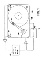
図1に示すように、2式のPZTセンサ101、102と信号処理方式を用いて、従来のシステム100(例えば、参考のためにここに掲載しているA. Jinzenji他の「ハードディスクドライブの回転方向外乱に対する加速度フィードフォワード制御」APMRC−Nov. 6-8、2000、TA6-01-TA6-02、特許文献5、Sidman他を参照)は、ランダム振動に対してフィードフォワード方式の対策を実施している。PZTセンサ101、102は他の技術革新なしに、それ自体で高品質の出力を発生するわけではない。図1はまたフィードフォワード補償器103と従来技術のサーボ104を示している。
【0013】
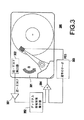
図2A−2Cに示すように、参考のためにここに掲載している特許文献6ではディスクドライブに2式のPZT構成システム201、202を設置しディスクドライブの質量と慣性を振動体として利用しかなりの感度で回転加速度と直線加速度を測定している。
【0014】
図2(a)はヘッドディスクアセンブリー200を示し、図2(b)は加速度測定用ピエゾエレクトリック歪計201,202を詳細に示し、図2(c)は衝撃と振動を受けるユーザ筺体204に搭載されたヘッドディスクアセンブリー200を示し、2式のPZT201,202が角加速度と直線加速度の信号を書き込み禁止信号が発行されるコンポーネト205に入力する。
【0015】
PZTを使用する上で他の問題は、PZTは複数の軸方向の歪に対して感度があり、シータダイナミックス以外の振動に対しても反応してしまうことである。100−1000Hzの帯域で忠実度の高い信号を発生するためには、PZTシステムは大きくなるが、その大きさは電子基板高さとディスクドライブ製造上の制約に合致しない。一方、PZTの寸法を小さくすると、信号品質が低下する(すなわち、特に低周波(100Hz以下)での信号ドリフトを容易に安定化することができない)。
【0016】
本発明者たちの実験の経験では、コンパクトなPZT構成体を使用する上で重要な問題は信号の安定化とノイズである。PZT信号が突然ドリフトすると不必要な書き込み中断が発生する。2式のPZTを使用することにより、各PZTのゲインと熱感度を合わせる必要が生じ、さらに問題が複雑になる。最新の機構を採用することにより、PZTの所期の方向での感度を向上し他の方向での感度を最小化することができる。しかしながら、センサのコストが上がりディスクドライブ用には使用するのが困難になる。
【0017】
他の方法では、小型機構静電容量検出器(例えば、C.Hernden「回転加速度計フィードフォワードを用いてHDDの振動を打ち消す」Data Storage, November, 2000, pp.22- 28を参照)を使用して高品質のシータ加速度検出器の作成を試みている。しかしながら、センサの大きさと帯域幅とコストの点が小型電子機構センサ(MEMS)の制約になると考えられる。
【0018】
【特許文献1】
米国特許第5608586号明細書
【特許文献2】
米国特許第5400196号明細書
【特許文献3】
特許第2565637号公報
【特許文献4】
米国特許第6122139号明細書
【特許文献5】
米国特許第5426545号明細書
【特許文献6】
米国特許第5721457号明細書
【0019】
【発明が解決しようとする課題】
このように、ランダム振動の問題はHDDのアクチュエータ系のトラック位置決め精度に極めて重大な影響を与えており、従来技術では適切に解決することは不可能である。さらに、シータダイナミックスにより発生するトラックはずれ誤差を回転速度センサを用いて最小化する方法またはシステムは知られていない。
【0020】
従来の方法及び装置の、前述の及び他の問題点、欠点及び不利な点に鑑みて、本発明の目的はHDDのアクチュエータ系のトラック追従精度に重大な影響を及ぼすランダム振動の問題に対する方法と構造の提供に取り組むことにある。
【0021】
本発明のもう1つの目的は、シータダイナミックスによるTMR誤差を回転速度センサを用いたアルゴリズムで最小化することにある。
【0022】
【課題を解決するための手段】
本発明の第一の特徴は、直線方向及び回転方向の振動にさらされるディスクドライブ(HDD)に回転方向振動のあらかじめ定めた周波数域の回転速度成分を検出する独立センサ部と、該独立センサ部の出力を受信するため最適化されたフィルタの組み合わせを有していることである。
【0023】
本発明の第二の特徴は、ディスクドライブの振動補償手段が中周波域の速度成分の抽出と、トラック追従誤差を減少させる制御信号を発生することを有していることである。
【0024】
本発明の第三の特徴は、ベースプレートを有するディスクドライブシステムの振動を測定する方法において、該ベースプレートの角速度成分に比例する逆−起電力(EMF)電圧を発生するセンサから出力される逆−起電力電圧をセンサから得ていることである。
【0025】
本発明の第四の特徴はディスクドライブシステムがメインボイスコイルモータと点中心に回転可能で直線方向振動には殆ど感度を有せずメインボイスコイルモータ(VCM)の磁束を選択的に検出する逆−起電力(EMF)センサを有していることである。
【0026】
発明ではディスクドライブのベースプレートの剛体運動は3直線軸方向(X、Y、Z)および3回転軸まわり(φ、ψ、θ)で発生すると考えている。ベースプレートのシータ面内での回転振動は、ディスクドライブで実現できるフィードバックサーボのゲインが有限であるため、トラッキング誤差の原因となる。
【0027】
一式に統合された電磁起電力(EMF)センサによりベースプレートの角速度を検出し、検出された速度を帯域制限微分器(BLDIF)を通すことにより、フィードフォワード制御アルゴリズムを形成しトラッキング誤差を相当に減らすことが可能である。
【0028】
従来システムの圧電(PZT)センサを用いた加速度フィードフォワード方式に対して、本発明の磁気方式速度検出ではHDDの直線方向の振動など不必要な振動の検出が比較的少ない。
【0029】
さらに、センサは実質的に電流ゼロの電圧検出モードで動作しているので、信号処理の条件は比較的厳しくなく、温度変動に伴う抵抗変化からの影響も少なく、電荷生成を用いたPZTセンサ法に比べ安価である。
【0030】
以上、本発明の回転振動(RV)速度を用いたサーボ補償法は従来の方法よりも有利であることが分かる。
【0031】
【発明の実施の形態】
上記の及びその他の目的、特徴及び利点は、以下の本発明の実施例の図を用いた詳細な説明からよく理解できる。図3−図14(d)に本発明の方法と構造の実施例を示す。
【0032】
図3では、ディスクドライブのアクチュエータがシーク中に反作用トルクを発生している。複数のドライブがアレイを形成して搭載されているコンピュータの構成では、ドライブから発生する複数の反作用が振動スペクトラムを生成する。
【0033】
振動スペクトラムの形と大きさ(例えば、直線方向および回転方向の両方)はシステムに固有であるが、有限な数の高調波に分散される帯域の限定されたパワースペクトラムであることが多い。ベース板振動の特にX,Y方向およびZまわり(例えばシータ軸)の振動がTMRに影響し得る。
【0034】
上記のようにTMRに大きく影響するのはシータダイナミックスである。アクチュエータの質量アンバラスはアクチュエータのピボットの直線方向振動からトルクを生じてTMRに影響するが、普通はアンバランス量は無視可能である。
【0035】
スピンドルモータ軸受けの弾性もまた、回転軸のX,Y振動により望ましくないTMRの原因となる。スピンドル軸受けがボールベアリングの場合より、流体軸受けの場合はより悪化すると考えられる。
【0036】
本発明はシータダイナミックスに起因するTMR誤差を回転速度センサを使用したアルゴリズにより最小とすることを目指している。図3(a)に示すように回転検出逆−EMFセンサ300がアルゴリズムを開発し有効性を実証するために使用されている。(低価格ディスクドライブに使用できるこのようなセンサを作成するのに要するイノベーションは上記の、参考のためここに記載するともに出願中の米国特許No.10/153687によって実現されたことを記載しておく。)
「フィードバック」と「フィードフォワード」は制御システムの分野では知られている一般的な原理である。従来システム(例えば特許文献2と特許文献3に開示されるような)はベースプレートの角加速度を測定し、同じ角加速度をアクチュエータアームに加えて対応するTMR成分を減少または除去するフィードフォワード法を採用している。測定されたRV加速度はゲインパラメータ(ノイズ削減処理とともに)により補正されてVCMアクチュエータに適用される。
【0037】
対策を実現するためには高品質のRV加速度検出技術が必要である。アルゴリズム自体は単純にゲイン調整処理である。しかしながら、信号処理の必要から、例えば信号ノイズの削減でフィードフォワードアルゴリズムを強化するイノベーションが行われ得る。
【0038】
本発明では開発が容易で低コストで作成できる、逆−EMFに基づくRV速度センサを使用することが望ましい。本発明の発明者たちは加速度センサの有するいかなる制約もRV速度センサを活用するアルゴリズム(例えば、方法)が見つかれば解決されると認識している。
【0039】
ディスクドライブの主VCMアクチュエータの設計で同じ経験をしているのでこれに基づいてシータ軸の角運動のみを検出する速度センサを設計することができる。従って、本発明ではアルゴリズム解(逆−EMFセンサなどが使用できると仮定して)を追及している。
【0040】
実用レベルのコンピュータ筺体はTMRを起こす共振点を約100から約1000Hzの帯域に有している。ストレージ業界はフルシークタイム10ms以下、1/3シークタイム5ms以下のディスクドライブを作成するのが一般になっている。この特性の傾向はランダム加振周波数が100Hz以下にはないと考えられることを意味する。最高周波数帯域では、1msのシングルトラックシークが1kHzに対応する(シークパルス強度はフルシークほど厳しくはない)。
【0041】
従って、コンピュータ筺体の任意の点でのランダム加振は約100Hzから約1000Hzの間に限られる。ファンなどの冷却系は60Hzの振動を生ずるがこれは現状のサーボループで処理される。従って、最悪の場合の加振は100−1000Hzの間にあり、最も発生の可能性の高いのは1/3またはそれ以下のシーク長に起因する200-800Hz帯域である。
【0042】
このように、本発明はフィードフォワードモード(例えば、100−1000Hz領域が望ましい)で有効なアルゴリズムを開発することを目標としている。アルゴリズム解を低周波(<100Hz)及び高周波(>1000Hz)領域で有効である必要がないと分かれば、RVを利用したHDDのアルゴリズム解が実現可能になる。この自明ではない仕様により解の現実的な実現が容易になる。本発明で中周波帯とは100−1000Hzを意味する。
【0043】
図3のディスクシステム300に示すように、ベースプレート301のRV速度は逆−EMFセンサ302で測定され、センサ302が出力した電圧は増幅され(例えば高ゲインアンプ351で)ディジタル化され(例えば、ディジタル帯域制限微分器352で)内蔵アルゴリズムの動作に使用される。位置誤差信号(PES)を受信し、アンプ(積分器)354に結合している通常のサーボ353がまた表示されている。図3のセンサ構成は単に1例であり、本発明はそれに限定されるものではないことを指摘しておく。
【0044】
このように、図3の構成は、動きが平面内運動だけでなく、同時に多くの軸に沿った直線運動の形を取りうるので、角加速度を検出/測定するのは高価であり、場合によっては適当でないことを考慮にいれている。それゆえ従来技術のPZTセンサを使用した場合クロスカップリングが起こり得る。
【0045】
発明者たちは従来技術のPZTセンサにはそのような問題があることを認識しており、PZTセンサとは異なる原理で機能する逆−EMFセンサを用いる技術を以下のように開発した。創意に満ちた逆−EMFセンサの構造は前述の共出願の米国特許No.10/153687に記載されている。
【0046】
逆−EMFセンサの構造と磁場中でコイル動作させて逆−EMFを検出することは(例えば物理の基礎原理である)一般に知られているが、ディスクドライブの角加速度/運動の検出に逆−EMFセンサを使用した例は知られていないことを指摘しておく。
【0047】
逆−EMFを本用途/問題点(例えば、ディスクドライブの角運動/回転の検出)を目的として使用するのは、新しくかつ例がない。実際に、アクチュエータ自体が点中心に回転支持されており、アクチュエータを動かして、そこで電圧計を使用すると電圧信号が生成される。しかしながら、アクチュエータの視点からそのような形でそのような構成が使われたことはない(あるいは以前に採用されたことも)。共出願にて説明しているように、逆−EMFセンサは逆−EMF検出用のコイル、空隙に磁束を発生する磁石、低摩擦ピボット、バランス用の質量などで構成することができる。
【0048】
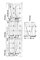
図4(a)−4(d)の説明を見ると、これらの図で、方法とアルゴリズムを形成する方法を体系的に説明しており、特にディスクドライブの回転運動学の洞察に基づいて、低周波(例えば25Hzなどの周波数以下)の要素は、従来技術のサーボでそれらの周波数の誤差と振動を扱うのに十分なゲインと能力があるので、興味の対象外である。
【0049】
低周波帯域と高周波帯域は振動対策に重大な問題ではないので、ハイパス(HP)フィルタ(例えば図4(a)の説明に示す)とローパス(LP)フィルタ(例えば図4(b)の説明に示す)を使用して、電圧のディジタル化の準備を行い、その後の処理に供する。フィルタは2次のタイプの25Hzのハイパス(HP)と7kHzのローパス(LP)のフィルタ機能のものが望ましい。このように信号はハイパスフィルタとローパスフィルタを順に通る。
【0050】
LP/HPフィルタ系の出力は次に補正されて「等価加速度」の情報が抽出される。しかしながら、測定された逆−EMF信号を単に微分しただけでは高周波(約>5kHz)の高レベルの雑音を生じやすい。理想的な微分器の伝達関数は90度の位相と周波数領域でデカードあたり20dBのゲインを有している。
【0051】
しかしながら、そのような微分器はセンサーノイズを高周波域で過剰に増幅し、ヘッド位置決めアクチュエータに好ましくない外乱を与える。したがって、最適な微分動作を行うアルゴリズムが絶対に必要である。
【0052】
中周波領域で微分機能を有する帯域制限微分器(例えば図3の352)が発明アルゴリズムの目標である。15Hzを「ゼロ」とし、7.5kHzを「極」とする一次のフィルタを選択することにより、効果的な帯域制限微分器352が設計され、特性を図4(c)に示す。
【0053】
この場合、帯域制限微分により、1kHzから7kHzの領域では微分は行われず、雑音が増幅されることも(信号の劣化も)避けられ、振動に起因する周波数から起こる同様の現象も避けられ、それゆえエラーの発生も避けられる。
【0054】
一方、300Hzから1kHzの間での同等な微分処理を得るために、微分は帯域制限微分器(図4(c)の上側の図)からの出力信号の90度位相を意味し、そして図4(c)の下側のボックスに示すように(位相プロットを示す)100Hz以下での位相は図示のように20度から60度で、そして80度に向かって上昇しその後90度に漸近していく。 しかしながら、高周波の信号は制限されることが望ましく、かなり高い周波数(例えば8-9kHz)では位相は0度に落ちる。
【0055】
このように、100-1000Hz域で意味のある微分器を提供することが望まれる(例えば、他のどこでもハイパスとローパスフィルタリング処理による信号の位相変化と信号振幅の制限のため信号が歪んでおり、他のどこでも信号が実際に崩れている)
図4(d)は図4(a)−4(c)に示すハイパス、ローパス及び帯域制限微分処理の結果(スペクトラム)を示す。明らかに、100Hzで約90度の位相が示され、これに対し約1000Hzでは80度より若干下にある。このように、本発明は±10度の位相進みで所期の周波数帯域(例えば100から約1000Hz)を得ることができる。よって、約90度位相の十分な位相進みをもって十分な微分処理を得ることができる。
【0056】
このように、中周波数帯域での位相進みは75度から95度であることが分かる。中周波数帯を超えると発明のアルゴリズムは位相仕様を逸脱する。しかしながら、想定されるRVスペクトラムはこの帯域を超えてアルゴリズムの有効性を求めてはいない。25Hzのハイパスフィルタは信号の低周波ドリフトを除去するが、ローパス周波数の選択は使用するセンサーシステムに応じてある程度柔軟に選択することができる。さらにローパス周波数に関しても同じことが言える。
【0057】
図4(a)−4(d)に示すように本発明の重要な特徴はハイパスとローパスフィルタが2次のフィルタブロックであることが推奨され、これに対して帯域制限微分器は1次のフィルタブロックであることが推奨されることを確認しておく。
【0058】
このように3ブロックは個別のフィルターステージと理解することができる。あるいは、3ステージを1次の(例えば、5次(5th)の多項式)ブロックに結合することもできる。3ステージが望ましい場合は、ステージの組み合わせが5次に等価であれば、HP,LP及びBLDIFのどのような組み合わせを選ぶことも可能である。ハイパスフィルタ(あるいはローパスフィルタ)のいずれかが望ましくない場合は4次のブロック及び1次のブロックを採用することが可能であることも確認しておく。
【0059】
しかしながら、好ましい多項式は5次のフィルタを最適に実現した図4(d)の形をとり、少し低いあるいは少し高い次数のモデルで実現されるであろうことさらに確認しておく。すなわち、モデルは図4(d)に示す形より少し高いあるいは少し低い次数に適合でき、同じレベルの機能を果たすことができる。
【0060】
以下にフィルタを相互に順番付ける方法及びフィルターステージのサンプルレートの選定法を説明する。ディジタルフィルターを実用的に作成する場合、従来のコントローラとは異なるサンプルレートを選択する必要がある場合がある。
【0061】
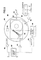
図5に本発明によるシステム500の実験(研究)装置を図示する。円形の台は電流ドライバー502/テーブル−アクチュエータ系(テ−ブル、アクチュエータは図示していない)に駆動されるRVテーブル501を有している。評価中のHDD503はドライブの電子回路にアクセスできるようベースプレートを上に向けてテーブル501上に設置されている。
【0062】
図5に示すように、ヘッド信号(図示されていない)が電子回路504から抽出され、特製のPES解読回路504により要求されるPESが解読される。
【0063】
HDD503のボード上のコントローラは実験のため作用を停止し、外部の信号処理システムがコントローラとして使用される。外部コントローラはトラック追従モードで従来技術のPIDと同様のコントローラの機能を実行する。アンプ511への入力を通常のサーボ510から出力しているのが示されている。信号Cはヘッドとトラックとの誤差を示す誤差信号を表す。
【0064】
ディジタル帯域制限微分器507からもう1つの信号がアンプ511へ入力され、比較処理が実行されVCM/アクチュエータ(図示せず)に駆動信号が送られる。
【0065】
逆−EMFセンサ505(例えば図3(a)に示す302と同様)が作成されテーブル501上にRVテーブル501の回転中心(円の中心)から離れて設置されRVにより生成された電圧は高ゲイン(-1000)回路506で増幅される。
【0066】
RV逆−EMF出力は高ゲインアンプ506を通って帯域制限微分器507が組み込まれているディジタル信号処理システム(例えば、トラック追従コントローラを実現したものと同じ)へ送られる。
【0067】
振動検出の参照とするため、1式の高品質のPZT加速度計508が使用され、アンプ512を通して信号が送られる。
【0068】
ダイナミック信号解析器(DSA)509が伝達関数測定機能を果たす。多様な点(A,B,C及びD)がDSA509に接続されデータが解析される。すなわち、信号Cと信号Dの比、信号Bと信号Aの比など多様な伝達関数の形態が調査されることができる。
【0069】
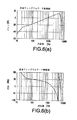
図6(a)−6(b)にRV速度センサを用いたコントローラの伝達関数(周波数領域でのB点とA点の比)の測定結果を示す。このように、コントローラは図4(d)(図4(d)の上下の線)の伝達関数計算結果(多項式)と対応している。
【0070】
v(n)をコントローラへの入力(図5のA点)とし、y(n)をコントローラの出力(図5のB点)とすると、この場合の有効な時間領域での計算式は(例えば、5次の多項式)は次の(1)式のようになる。
【0071】
【数1】

ここで、n、n−1、・・・・はそれぞれの変数の時間遅れサンプルに対応し、k1、・・・、k9は本発明に基づく所期の特性を得るために選択されたゲインに対応する。
【0073】
ゲインは一般には定数であるが、アルゴリズムの効果を向上するために、ドライブシステム特性あるいは振動環境に応じて更新することが可能である。
【0074】
上記の計算式はHP,LP及びBLDIFフィルタの合成と等価である。浮動小数点演算器を有するHDDシステムでは本計算式は直接実行することができる。低パワーの整数計算プロセッサーのHDDの場合は、以下に説明するように、各フィルタ機能を独立した信号処理ブロックとして有することが必要と考えられる。
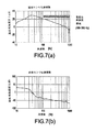
【0075】
図7(a)と7(b)にRVコントローラアルゴリズム作成時に使用した逆−EMFセンサ(例えば図5の505)の伝達関数測定結果を示す(出力としてA点、入力としてD点の信号の比)。速度/角加速は周波数領域で測定される。
【0076】
出力は逆−EMFセンサ505の電圧(増幅後)であり、入力は RVテーブル上に設置された(例えば図5の501)高品質直線方向加速度計508で測定されたセンサ505に加わる回転加速度に対応する電圧である。
【0077】
約40Hz以下の周波数ではセンサ特性はピボット剛性で支配されることが分かる。約40Hzを超えるとセンサ特性はその慣性に支配される。
【0078】
図7(b)に示す位相特性はピボットに起因する減衰効果を示している。理想的には、搭載されている台の回転速度を抽出するため、センサは90度の位相ずれとデカードあたり20dBの減衰を有することが必要である。100Hzから800Hzの中周波数ではセンサ特性は本仕様にほぼ合致するが、完璧にではない。このように、センサ/コントローラの構成の自明ではないが有している潜在特性を明らかにするためにはさらに実験的評価が必要である。
【0079】
図7(a)−7(b)に示すように、発明の最も関心のある周波数帯域は約100から約1000Hzであることを再度確認しておく。すなわち、本発明が関心を有する主たる活動はこの領域の中にある。
【0080】
例えば、一般的なディスクハウジングのトラック追従誤差(TMR)共振周波数は約100から約1000Hzの帯域にある。一般的に、5msシーク(5msの方形なパルスを生成する、現在の平均シークタイム)は200Hzに対応し、10msシークは100Hzに対応する。他の使用されるパルスは1msから3msの間にある。2msパルスは約500Hzに対応する。一般に1msより短いシーク(1kHzに対応する)は存在しない。
【0081】
このように、センサの有効な部分は約10−1000Hzの帯域で動作する。従って、創意に富む方法を使用している本発明のセンサは独立のセンサとして使用することができる。
【0082】
図8に3つの条件下でのRVのPESへの効果を示す。すなわち、図8に出力PES(例えば、図5の信号C)と入力RV(例えば、PZT出力で測定された信号B)との比を示す。
【0083】
従来技術の場合の801は補償制御(例えばフィードフォワード)のためのRV加速度あるいは速度検出がないときの波形である(補償制御はフィードフォワードなし)。このように、1単位G入力(例えば、100Hzで40dB)に対して、位置誤差信号(PES−信号C)の1トラック幅の誤差は256ビットに相当する。従って、100ビットは約半トラック幅に相当する。このように、従来技術の場合は40dB(1G)は100ビットに相当し、従来技術のサーボループの構造では問題を解決することはできない。
【0084】
つぎのケース802では、高感度PZT(例えば、高価な2重PZTセンサ)を有する最善の構成で、PZT信号はLP、HPフィルターされアクチュエータにフィードフォワードされる。このようにPZT加速度法に示すように性能は良いが、コストが極めて高くなりさらにサイズも大きくなる。
【0085】
802の波形に示される興味あるケースはRV速度基準の制御である。両方のセンサは類似の振動除去特性を有するが、逆−EMFセンサ(例えば曲線803で示される)はPZT基準の制御より減衰が小さい(8−10dB)。さらに逆−EMFセンサはPZT法より大幅に安価でサイズも小さくディスクドライブの機構部品の中に使えるスペースを確保することが可能である。
【0086】
最良のPZTシステムに比較する性能を出せるように逆−EMFセンサを最適設計できることが分かった。実際、150Hz以下の低周波数では逆−EMFに基づく構成で改善された補償が施される。検出と制御の方法が基本的に異なるので伝達関数(TF)も相違する。TFは正弦波掃引法で求められる。
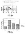
【0087】
図9(a)−9(b)にランダム回転方向振動に対する動作特性を示す。図9(a)は実験的に生成したランダムRVのスペクトラムである。 スペクトル特性は特別なプログラム可能な波形発生器を用いて生成され、サーバーシステムで一般的に見られるRV特性を模擬している。図に示すように振動スペクトラムには実験テーブルの加振により発生する約300Hzと約600Hzに山がある。
【0088】
図9(b)はランダム回転方向振動に対する動作特性を示し、より詳細には入力RV値22.8r/s2に対応するPES(1シグマ)値を示す。従来技術の制御ではPES値は21あるいは22−ビット(1シグマ)と4倍になることが示されている。
【0089】
RV速度センサに基づく制御では、PES値は、12から13ビット(13dB)に低下し、ほぼ理想的なPZT(例えば高品質、高価な2重PZTセンサ構成)では、さらに11ビット(11dB)まで改善される。振動がないときには、6ビットが観測されるだろう(例えば、従来技術のサーボ制御での静止状態で)。
【0090】
図10(a)は対応するPESのパワースペクトラム(例えば、サーバのランダム振動PESのスペクトラム)を示す。RVセンサーに基づく制御の約60Hzから100Hzでの有効性が見える。
【0091】
350Hzから525Hz間の帯域でのランダムRVに基づくPESの詳細を図10(b)に示す。各構成(従来技術、RV速度及びPZT加速度)でPESパワー密度が段階的に減少するのが見える。すなわち、静止状態と補償状態の阻止特性から200−300Hz領域での優位性が示されている。さらに、「山」の部分に振幅の減少が示されている(図9(b)の1シグマ値の山を参照)
図11(a)−11(c)にRV速度センサに基準のコントローラの有無での一定正弦波RV加振(例えば100Hz、18.6rad/s2の正弦波角度振動)の結果を示す。図11(a)では、速度センサが振動入力を受信し、さらに信号を出力する。
【0092】
実質的なPES振幅の減少は従来技術のサーボでのトラック追従状態を示す図11(b)と速度検出トラック追従状態(フィードフォワードによる)を示す図11(c)を比較すると見ることができる。
【0093】
図12にシステム1200に、逆−EMFセンサ1201とLP1202,HP1203及びDIF1204を有する対応フィルタ列を実際に適用した例を示す。LP1201を第一ステージとして使用すると高周波成分が直ちに除去される。サンプリング周波数f2は従来技術のコントローラの周波数f1に等しくても異なっても良い。高サンプリング周波数の方が中周波数帯域で位相ロスが減少するので望ましい。
【0094】
しかしながら、トレードオフとして、サンプリング周波数とコーナー周波数(例えば、BLDIFの15HzとHPの25Hz)の差が大きくなると、HP及びBLDIFフィルタの定数(A,B及びC)が大きくなってしまうことがある。大きな定数を有限の整数語長のプロセスで保持するのは困難である。従って、実施条件に合うようにf2を選択できることが重要である。フィルタ周波数の選択において、有限語長の制約を満たすため、各フィルタHP,LP及びBLDIFが異なる周波数で動作することを選択することが必要となることもありうる。
【0095】
図12に示すフィルタ後のゲイン「k」は振動補償が必要でないとき、スイッチ(例えば「k=0」はフィードフォワード制御なし)として使用することができる。HDDが1台のみ使用されているとき、ランダム振動は殆ど発生せず、RV速度センサを読める管理コントローラがゲインkをゼロに設定してフィードフォワード処理を無効にすることができる。
【0096】
図12はまたアナログアンプ1205、管理コントローラ1206、トラック追従回路1207、さらに各種サンプル回路1208A、1208B及び1208C、足し算回路1209、アクチュエータ電流ドライバー1210及びアクチュエータVCM1211を示している。
【0097】
本発明は、全てアナログ電子回路で実施することも、全てディジタル電子回路で実施することも、その組み合わせで実施することも可能であることを図12は示していることを指摘しておく。装置をプログラミングできる(例えば製造後に)ことからディジタル電子回路の方が望ましい。
【0098】
図12に示すフィルタリングの適用は単なる代表例であることをさらに加えておく。すなわち、上述のように、LP,HP及び/またはDIFの組み合わせは単に「ブラックボックス」で5次の多項式(例えば上記の方程式による)のフィルタ1212を表しており、含まれるコンポーネントは上記のように低次のフィルターステージ1、ステージ2及びステージ3コンポーネントであると考えることができる。
【0099】
上記のように、本発明は他に類例がなく、自明ではない特徴を有しており、独立したセンサから得られる逆−EMF信号に基づいて動作する1つの方法(アルゴリズム)が開発された。主アクチュエータVCMも逆−EMFを発生するが、トラック追従制御動作の影響に支配される。インテリジェント電子回路を通して2つの逆−EMF(すなわちトラック追従とRV)の成分は分離される。このように主アクチュエータの逆−EMFを制御の向上あるいはRV推定に活用することができる。
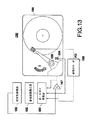
【0100】
図13に主アクチュエータの逆−EMFがRV制御に利用されているシステム1300の構成を示す。図13では、逆−EMF推算器1301が総合アクチュエータ電流コマンド、トラック追従電流コマンドおよびHDD温度(センサ1304が使えれば)情報を選択したサンプリング周波数で受信する。このブロックの出力は、ベースプレート1305と主アクチュエータVCM1306の相対運動に対応する逆−EMFの推定値である。BLDIF1302と安定補償器1303は、この第二のフィードバックループを完成している。アンプ1307と通常のサーボ1308も示されている。
【0101】
トラック追従コマンドに基づくアクチュエータの動作がこの第二の制御ループ(要素1301,1302及び1303)の影響を受けてはならないことが示されている。図13に示す方法に対する制約は同じ主VCMから得られるPESと逆−EMFが独立ではないことで、逆−EMFを従来技術のフィードバックに加えて第二のフィードバックループとして使用すると制御を混乱させ、不安定になる場合まである。しかしながら、新しいアルゴリズムの開発でRVの強化が可能になった。
【0102】
図14(a)−14(d)に本発明に使用する速度センサの応答した過渡振動のパターンへの効果を示す。詳細には、図14(a)は従来技術のPZTセンサの応答を示し、図14(b)は本発明による速度センサの応答を示す。図14(c)はフィードフォワード補償のないときのアクチュエータ位置誤差(PES)を時間軸上で示し、図14(d)はフィードフォワード補償により改善したPESを示す。
【0103】
上記のハードウェア/ソフトウェア環境に加えて、本発明の別の方式ではコンピュータにより上記の方法を実現することができる。例えば、この方法は上記で説明した環境で実現することができる。
【0104】
この方法は、例えば、機械で読み取り可能な命令の連続を実行するディジタルデータ処理機器として実現されるコンピュータを操作することにより実現可能である。これらの命令は各種の信号保持媒体に保存可能である。
【0105】
信号を保存する媒体としては、例えば高速アクセスストレージであるCPU内のRAMが挙げられる。あるいは、CPUから直接または間接にアクセスされる磁気データ保存ディスケットなど、他の信号保存媒体に命令を保存することも可能である。
【0106】
ディスケット、コンピュータ/CPUあるいは他のどこであったとしても、命令を機械で読み取り可能な、DASDストレージ(通常の「ハードドライブ」またはRAIDアレイ)、磁気テープ、電子的読み取り専用メモリ(例えば、ROM,EPROMまたはEEPROM)、光ストレージ装置(例えばCD-ROM,WORM,DVD、ディジタル光テープなど)紙「パンチ」カード、あるいは他の、ディジタル及びアナログ通信回線及び無線などの通信媒体も含めて、適当な信号保存媒体などの多様なデータ保存媒体に保存することができる。本発明の実施例の説明図では機械読み取り可能命令は「C」言語などからコンパイルされたソフトウェアのオブジェクトコードとなっている。
【0107】
本発明をいくつかの好適な実施例を用いて記述したが、本技術分野に習熟した人には、発明の趣旨と特許請求項の範囲で修正して発明を実施することが可能であることが理解される。
【0108】
【発明の効果】
本発明によれば、HDDのアクチュエータ系のトラック追従精度に重大な影響を及ぼすランダム振動の問題に対する方法と構造を提供することができる。また、シータダイナミックスによるTMR誤差を回転速度センサを用いたアルゴリズムで最小化することができる。
【図面の簡単な説明】
【図1】従来手法によるPZTセンサ101,102を用いた加速度フィードフォワード制御を示す図である。
【図2】従来手法の角加速度の検出におけるPZTセンサ2式201,202の使用法を示す図である。
【図3】ディスクドライブ300の逆−起電力(EMF)検出法とフィードフォワードループ(アルゴリズム)を示す図である。
【図4】図3のフィードフォワードループ(アルゴリズム)の要素、ハイパスフィルタ(図4(a))、ローパスフィルタ(図4(b))、帯域制限微分操作(図4(c))、及び図4(a)−4(c)の合成伝達関数(図4(d))をそれぞれ示す図である。
【図5】 RV制御とセンサの利点を評価するための実験装置を示す図である。
【図6】帯域制限微分方式のRV制御器の伝達関数の測定結果を示す図である。
【図7】逆−EMFセンサ(入力:RV加速度、出力:逆−EMF)の伝達関数の測定結果を示す図である。
【図8】さまざまな制御条件におけるRV加速度の入力に対応する位置誤差信号(PES)の伝達関数の測定結果を示す図である。
【図9】それぞれRV振動入力と対応するPES(1シグマ)特性の周波数スペクトラムを示す図である。
【図10】コントローラとセンサの各構成でのPESの周波数スペクトラムを示す図である。
【図11】固定周波数での正弦波加振に対する応答を示す図であり、より詳細には図11(a)は正弦波角方向振動入力を示し、図11(b)は従来技術のトラック追従状態を示し、そして図11(c)は速度検出方式のトラック追従状態を示す。
【図12】本発明のRV速度フィードフォワードアルゴリズムの方式を示す図である。
【図13】逆−EMF生成装置として作用する主アクチュエータボイスコイルモータ(VCM)を示す図である。
【図14】過渡振動への従来技術のPZTセンサ(図14(a))と本発明に使用する速度センサ(図14(b))の応答、及びフィードフォワード補償のない場合のアクチュエータの位置決め誤差と時間経過後の位置決め誤差(PES)(図14(c))とフィードフォワード補償によるPESの改善結果(図14(d))を対応して示す図である。
【符号の説明】
300,503…ディスクシステム、
301…ベースプレート、
302,505,1201…逆―EMFセンサ、
351,506,1205…高ゲインアンプ、
352,507…ディジタル帯域制限微分器、
354,511…アンプ(積分器)、
1202…ローパスフィルタ(LP)、
1203…ハイパスフィルタ(HP)、
1204…微分器(DIF)、
1206…管理コントローラ、
1207…トラック追従回路、
1208A,1208B,1208C…サンプル回路、
1209…足し算回路、
1210…電流ドライバー、
1211…アクチュエータVCM。[0001]
BACKGROUND OF THE INVENTION
The present invention relates generally to a disk drive, and more particularly to a disk drive that minimizes track deviation (TMR) due to theta dynamics using a rotational speed sensor with state-of-the-art algorithms.
[0002]
[Prior art]
As track density continues to increase, track following error due to vibration has become a very significant problem in the operation of disk drives. The effective data transfer rate and processing capacity are reduced by rotational vibration. At high density (high tracks per inch (TPI)), disk drive in-plane rotational vibration (eg, theta axis), called “Theta Dynamics”, directly affects the track deviation (TMR) factor. give.
[0003]
Countermeasures for this vibration problem can be examined by various methods ranging from the latest mounting methods to sophisticated sensors and servo algorithms.
[0004]
A computer system may include one or more disk drives, and each drive causes a vibration environment as a whole. Furthermore, the computer system itself may be vibrated from the outside by an earthquake. The head positioning accuracy of a disk drive is susceptible to the vibrations of its own and the vibrations of nearby disk drives or other peripheral devices assembled in the same housing.
[0005]
Current generation hard disk drives (HDDs) of type 1.0, 2.5 and 3.5 are designed to operate in portable and desktop / server environments, respectively. In order to reduce the cost and weight of computer systems, manufacturers generally make HDD housings with thin plate structures. Therefore, the computer enclosure is a flexible structure and is susceptible to vibration. Due to such a mounting structure, the disk drive is unstable with respect to vibration generated from inside or outside. Rotary actuator type HDDs are particularly susceptible to in-plane vibrations of the base plate.
[0006]
The HDD head positioning servo system performs three important functions. First, the servo system moves the head to the vicinity of the target in the shortest time by the speed servo in seek mode. Next, the head is positioned on the target track with minimum settling time using position control that does not have an integral term (eg, capability). Finally, the servo system enters the track-follow mode of proportional-integral-derivative (PID) type position control.
[0007]
However, during the seek mode, a deceleration torque is generated from a voice coil motor (VCM) type actuator following the maximum rotational acceleration torque. The repulsive torque causes transient rotational vibrations in the base plate, which can adversely affect the read / write head positioning accuracy. However, randomly generated vibrations have a significant impact on track tracking accuracy (and some settling performance). Prior to the present invention, none of the problems of random vibration has been pointed out properly, which has a profound effect on the track following accuracy of an HDD actuator system.
[0008]
Today's 3.5-inch disk drives have reached 40 kTPI and are expected to exceed 50 kTPI after 2001. A major problem in increasing the track density is that the head positioning accuracy decreases due to the disturbance of vibration. Due to the exponential growth of TPI, track positioning of read / write components has become a major challenge. Existing servo systems are required to continually innovate in order to function under increasingly difficult operating conditions.
[0009]
Since mechanical parts such as a spindle motor are not completely balanced in mass, they generate harmonic vibration during operation. Harmonic vibration causes vibration in a linear direction and a rotational direction with respect to the entire HDD system. Without compensation, track following errors can be as much as 15% of the track pitch, which can adversely affect both “soft” and “hard” failure rates of disk drives. The positioning error due to the periodic vibration generated inside can be solved by the servo method disclosed in
[0010]
Due to the special mounting design that absorbs shock and vibration, the rotational vibration component due to the vibration of the built-in spindle is minimized as taught in
[0011]
Similarly,
[0012]
As shown in FIG. 1, using two
[0013]
As shown in FIGS. 2A-2C, in Patent Document 6 listed here for reference, two
[0014]
2 (a) shows the
[0015]
Another problem in using PZT is that PZT is sensitive to multiple axial strains and reacts to vibrations other than theta dynamics. In order to generate high fidelity signals in the 100-1000 Hz band, the PZT system is large, but its size does not match the constraints on electronic board height and disk drive manufacturing. On the other hand, if the size of the PZT is reduced, the signal quality deteriorates (that is, the signal drift cannot be easily stabilized particularly at a low frequency (100 Hz or less)).
[0016]
In our experimental experience, the important issues in using compact PZT constructs are signal stabilization and noise. When the PZT signal suddenly drifts, unnecessary write interruption occurs. By using two types of PZT, it is necessary to match the gain and thermal sensitivity of each PZT, and the problem is further complicated. By adopting the latest mechanism, the sensitivity in the intended direction of PZT can be improved and the sensitivity in other directions can be minimized. However, the cost of the sensor increases, making it difficult to use for a disk drive.
[0017]
Other methods use small-mechanism capacitance detectors (see, for example, C. Hernden "Canceling HDD Vibration Using Rotational Accelerometer Feedforward" Data Storage, November, 2000, pp. 22-28) I am trying to make a high quality theta acceleration detector. However, the size, bandwidth, and cost of the sensor are considered to be limitations of the small electronic mechanism sensor (MEMS).
[0018]
[Patent Document 1]
US Pat. No. 5,608,586
[Patent Document 2]
US Pat. No. 5,500,196
[Patent Document 3]
Japanese Patent No. 2565637
[Patent Document 4]
US Pat. No. 6,122,139
[Patent Document 5]
US Pat. No. 5,426,545
[Patent Document 6]
US Pat. No. 5,721,457
[0019]
[Problems to be solved by the invention]
As described above, the problem of random vibration has a very serious influence on the track positioning accuracy of the actuator system of the HDD, and cannot be properly solved by the prior art. Furthermore, there is no known method or system for minimizing track misalignment errors caused by theta dynamics using rotational speed sensors.
[0020]
In view of the foregoing and other problems, disadvantages, and disadvantages of conventional methods and apparatus, it is an object of the present invention to provide a method and method for the problem of random vibration that significantly affects the track following accuracy of an HDD actuator system. It is to work on providing structure.
[0021]
Another object of the present invention is to minimize the TMR error due to theta dynamics with an algorithm using a rotational speed sensor.
[0022]
[Means for Solving the Problems]
A first feature of the present invention is an independent sensor unit that detects a rotational speed component in a predetermined frequency range of rotational vibration in a disk drive (HDD) that is exposed to linear and rotational vibrations, and the independent sensor unit Having a combination of filters optimized to receive the output.
[0023]
The second feature of the present invention is that the vibration compensation means of the disk drive has a function of extracting a velocity component in the middle frequency region and generating a control signal for reducing the track following error.
[0024]
According to a third aspect of the present invention, there is provided a method for measuring vibration of a disk drive system having a base plate, wherein a back-electromotive force (EMF) voltage output from a sensor that generates a back-electromotive force (EMF) voltage proportional to the angular velocity component of the base plate. The power voltage is obtained from the sensor.
[0025]
The fourth feature of the present invention is that the disk drive system can rotate about the center of the point with the main voice coil motor and has little sensitivity to linear vibration, and reversely detects the magnetic flux of the main voice coil motor (VCM) selectively. It has an electromotive force (EMF) sensor.
[0026]
In the invention, it is considered that the rigid body motion of the base plate of the disk drive occurs in the three linear axis directions (X, Y, Z) and around the three rotation axes (φ, ψ, θ). The rotational vibration in the theta plane of the base plate causes a tracking error because the gain of the feedback servo that can be realized by the disk drive is finite.
[0027]
A set of integrated electromagnetic electromotive force (EMF) sensors detect the angular velocity of the baseplate and pass the detected velocity through a band-limited differentiator (BLDIF) to form a feedforward control algorithm and significantly reduce tracking errors It is possible.
[0028]
Compared to the acceleration feedforward method using the piezoelectric (PZT) sensor of the conventional system, the magnetic method speed detection of the present invention detects relatively few unnecessary vibrations such as vibrations in the linear direction of the HDD.
[0029]
Furthermore, since the sensor is operating in a voltage detection mode with substantially no current, the signal processing conditions are relatively strict, and there is little influence from resistance changes due to temperature fluctuations. PZT sensor method using charge generation Is cheaper than
[0030]
As described above, it can be seen that the servo compensation method using the rotational vibration (RV) speed of the present invention is more advantageous than the conventional method.
[0031]
DETAILED DESCRIPTION OF THE INVENTION
The above and other objects, features and advantages can be better understood from the following detailed description using drawings of embodiments of the invention. 3-14 (d) show an embodiment of the method and structure of the present invention.
[0032]
In FIG. 3, the disk drive actuator generates a reaction torque during seeking. In a computer configuration in which a plurality of drives are mounted in an array, a plurality of reactions generated from the drives generate a vibration spectrum.
[0033]
The shape and magnitude of the vibration spectrum (eg, both linear and rotational directions) is inherent in the system, but is often a limited power spectrum with a band distributed over a finite number of harmonics. Base plate vibrations, particularly in the X and Y directions and around Z (eg, theta axis), can affect TMR.
[0034]
As described above, theta dynamics greatly affects TMR. The mass unbalance of the actuator generates torque from the linear vibration of the pivot of the actuator and affects the TMR, but the unbalance amount is usually negligible.
[0035]
The elasticity of the spindle motor bearing also causes unwanted TMR due to the X and Y vibrations of the rotating shaft. It is considered that the case of a fluid bearing is worse than the case of a spindle bearing being a ball bearing.
[0036]
The present invention aims to minimize the TMR error caused by theta dynamics by an algorithm using a rotational speed sensor. As shown in FIG. 3 (a), a rotation detection reverse-
“Feedback” and “feedforward” are general principles known in the field of control systems. Conventional systems (such as those disclosed in
[0037]
High quality RV acceleration detection technology is necessary to realize the countermeasures. The algorithm itself is simply a gain adjustment process. However, because of the need for signal processing, innovations can be made that enhance the feedforward algorithm, for example, by reducing signal noise.
[0038]
In the present invention, it is desirable to use a reverse-EMF based RV speed sensor that is easy to develop and can be produced at low cost. The inventors of the present invention recognize that any limitation of an acceleration sensor can be solved if an algorithm (eg, method) that utilizes an RV velocity sensor is found.
[0039]
Based on this experience, we can design a velocity sensor that detects only the angular motion of the theta axis. Therefore, the present invention pursues an algorithm solution (assuming that an inverse-EMF sensor or the like can be used).
[0040]
A practical computer enclosure has a resonance point that causes TMR in a band of about 100 to about 1000 Hz. In the storage industry, it is common to create disk drives with a full seek time of 10 ms or less and a 1/3 seek time of 5 ms or less. This tendency of characteristics means that the random excitation frequency is not considered to be less than 100 Hz. In the highest frequency band, a 1 ms single track seek corresponds to 1 kHz (the seek pulse intensity is not as strict as a full seek).
[0041]
Therefore, random excitation at any point on the computer enclosure is limited to between about 100 Hz and about 1000 Hz. A cooling system such as a fan generates 60 Hz vibration, which is handled by the current servo loop. Thus, the worst case excitation is between 100-1000 Hz and the most likely occurrence is in the 200-800 Hz band resulting from a seek length of 1/3 or less.
[0042]
Thus, the present invention aims to develop an algorithm that is effective in feedforward mode (eg, the 100-1000 Hz region is desirable). If it is known that the algorithm solution does not need to be effective in the low frequency (<100 Hz) and high frequency (> 1000 Hz) regions, an HDD algorithm solution using RV can be realized. This non-obvious specification facilitates realistic realization of the solution. In the present invention, the medium frequency band means 100-1000 Hz.
[0043]
As shown in the
[0044]
Thus, the configuration of FIG. 3 is expensive to detect / measure angular acceleration because the motion can take the form of not only in-plane motion but also linear motion along many axes simultaneously. Is taken into account. Therefore, cross-coupling can occur when using prior art PZT sensors.
[0045]
The inventors have recognized that the conventional PZT sensor has such a problem, and have developed a technique using an inverse-EMF sensor that functions on a principle different from that of the PZT sensor as follows. The structure of the inventive reverse-EMF sensor is described in the aforementioned co-pending US Patent No. 10/153687.
[0046]
Inverse-EMF sensor structure and coil-operating in a magnetic field to detect inverse-EMF are generally known (for example, the basic principle of physics). It should be pointed out that no example using an EMF sensor is known.
[0047]
The use of inverse-EMF for this purpose / problem (eg, detection of angular motion / rotation of a disk drive) is new and unprecedented. In fact, the actuator itself is rotationally supported around a point, and when the actuator is moved and a voltmeter is used there, a voltage signal is generated. However, such a configuration has never been used in that way (or previously adopted) from an actuator perspective. As described in the co-application, the reverse-EMF sensor can be composed of a coil for detecting reverse-EMF, a magnet for generating a magnetic flux in the air gap, a low friction pivot, a mass for balancing, and the like.
[0048]
Looking at the description of FIGS. 4 (a) -4 (d), these diagrams systematically explain the method and method of forming the algorithm, especially based on insights into the rotational kinematics of disk drives, Low frequency elements (eg, below 25 Hz) are not of interest because they have sufficient gain and ability to handle those frequency errors and vibrations with prior art servos.
[0049]
Since the low frequency band and the high frequency band are not serious problems for vibration countermeasures, a high-pass (HP) filter (for example, shown in the description of FIG. 4 (a)) and a low-pass (LP) filter (for example, the description of FIG. 4 (b)). To prepare for digitization of the voltage for subsequent processing. The filter preferably has a second-
[0050]
The output of the LP / HP filter system is then corrected to extract “equivalent acceleration” information. However, simply differentiating the measured back-EMF signal is likely to produce high-level (about> 5 kHz) high-level noise. The ideal differentiator transfer function has a gain of 20 dB per decard in the 90 degree phase and frequency domain.
[0051]
However, such a differentiator excessively amplifies the sensor noise in the high frequency range and gives an undesired disturbance to the head positioning actuator. Therefore, an algorithm that performs optimal differentiation is absolutely necessary.
[0052]
A band-limited differentiator having a differentiation function in the middle frequency region (for example, 352 in FIG. 3) is a target of the invention algorithm. By selecting a first order filter with 15 Hz as “zero” and 7.5 kHz as “pole”, an effective band
[0053]
In this case, due to the band-limited differentiation, differentiation is not performed in the region of 1 kHz to 7 kHz, noise can be prevented from being amplified (signal degradation), and a similar phenomenon caused by the frequency caused by vibration can be avoided. Therefore, the occurrence of errors can be avoided.
[0054]
On the other hand, to obtain an equivalent differentiation process between 300 Hz and 1 kHz, differentiation means the 90 degree phase of the output signal from the band limited differentiator (upper figure of FIG. 4 (c)), and FIG. (c) As shown in the lower box (shown in the phase plot), the phase below 100 Hz is 20 to 60 degrees as shown and then increases to 80 degrees and then asymptotically approaches 90 degrees. Go. However, it is desirable that high frequency signals be limited, and the phase drops to 0 degrees at fairly high frequencies (eg, 8-9 kHz).
[0055]
Thus, it is desirable to provide a meaningful differentiator in the 100-1000 Hz range (for example, the signal is distorted due to signal phase change and signal amplitude limitation by high-pass and low-pass filtering processing everywhere, The signal is actually broken everywhere else)
FIG. 4D shows the result (spectrum) of the high-pass, low-pass and band-limited differential processing shown in FIGS. Obviously, a phase of about 90 degrees is shown at 100 Hz, while it is slightly below 80 degrees at about 1000 Hz. As described above, the present invention can obtain an intended frequency band (for example, 100 to about 1000 Hz) with a phase advance of ± 10 degrees. Therefore, a sufficient differential process can be obtained with a sufficient phase advance of about 90 degrees.
[0056]
Thus, it can be seen that the phase lead in the middle frequency band is 75 degrees to 95 degrees. Beyond the middle frequency band, the inventive algorithm deviates from the phase specification. However, the assumed RV spectrum does not require algorithm effectiveness beyond this band. The 25 Hz high pass filter removes low frequency drift of the signal, but the selection of the low pass frequency can be selected with some flexibility depending on the sensor system used. The same is true for the low pass frequency.
[0057]
As shown in FIGS. 4 (a) -4 (d), it is recommended that the high-pass and low-pass filters are second-order filter blocks as an important feature of the present invention. Make sure that the filter block is recommended.
[0058]
Thus, the three blocks can be understood as individual filter stages. Alternatively, the third stage is the first order (for example, the fifth order (5 th ) Polynomial) block. If three stages are desired, any combination of HP, LP and BLDIF can be selected as long as the combination of stages is fifth order equivalent. It is also confirmed that if any of the high-pass filter (or low-pass filter) is not desirable, it is possible to employ a quartic block and a primary block.
[0059]
However, it is further confirmed that the preferred polynomial takes the form of FIG. 4 (d) which optimally implements a fifth order filter and will be realized with a slightly lower or slightly higher order model. That is, the model can fit orders that are slightly higher or slightly lower than the shape shown in FIG. 4 (d) and can perform the same level of function.
[0060]
A method for ordering the filters and a method for selecting the sample rate of the filter stage will be described below. When creating a digital filter practically, it may be necessary to select a different sample rate than a conventional controller.
[0061]
FIG. 5 illustrates an experimental (research) apparatus for a
[0062]
As shown in FIG. 5, a head signal (not shown) is extracted from the
[0063]
The controller on the board of
[0064]
Another signal is input to the
[0065]
A reverse-EMF sensor 505 (for example, similar to 302 shown in FIG. 3A) is created and placed on the table 501 away from the rotation center (the center of the circle) of the RV table 501, and the voltage generated by the RV is a high gain. (-1000) Amplified by
[0066]
The RV inverse-EMF output is sent through a
[0067]
A set of high
[0068]
A dynamic signal analyzer (DSA) 509 performs the transfer function measurement function. Various points (A, B, C and D) are connected to the
[0069]
FIGS. 6 (a) -6 (b) show the measurement results of the transfer function (ratio between point B and point A in the frequency domain) of the controller using the RV speed sensor. In this way, the controller corresponds to the transfer function calculation result (polynomial) in FIG. 4D (upper and lower lines in FIG. 4D).
[0070]
Assuming that v (n) is an input to the controller (point A in FIG. 5) and y (n) is an output of the controller (point B in FIG. 5), an effective time domain calculation formula in this case is (for example, The fifth-order polynomial) is expressed by the following equation (1).
[0071]
[Expression 1]
Here, n, n-1,... Correspond to the time delay samples of the respective variables, and k1,..., K9 are gains selected to obtain the desired characteristics according to the present invention. Correspond.
[0073]
The gain is generally a constant, but can be updated according to drive system characteristics or vibration environment to improve the effectiveness of the algorithm.
[0074]
The above formula is equivalent to the synthesis of HP, LP and BLDIF filters. In an HDD system having a floating point arithmetic unit, this calculation formula can be directly executed. In the case of an HDD with a low power integer calculation processor, it is considered necessary to have each filter function as an independent signal processing block, as described below.
[0075]
7 (a) and 7 (b) show the transfer function measurement results of the inverse-EMF sensor (for example, 505 in FIG. 5) used when creating the RV controller algorithm (the ratio of the signal at point A as output and the signal at point D as input). ). Velocity / angular acceleration is measured in the frequency domain.
[0076]
The output is the voltage of the inverse-EMF sensor 505 (after amplification), and the input is the rotational acceleration applied to the
[0077]
It can be seen that the sensor characteristics are dominated by the pivot stiffness at frequencies below about 40 Hz. Above about 40 Hz, the sensor characteristics are governed by its inertia.
[0078]
The phase characteristic shown in FIG. 7 (b) shows the damping effect due to the pivot. Ideally, the sensor should have a 90 degree phase shift and an attenuation of 20 dB per decard to extract the rotational speed of the mounted platform. At medium frequencies from 100Hz to 800Hz, the sensor characteristics almost match this specification, but not perfectly. Thus, further experimental evaluation is necessary to clarify the latent characteristics that the sensor / controller configuration is not obvious.
[0079]
As shown in FIGS. 7 (a) -7 (b), it is reconfirmed that the most interesting frequency band of the invention is about 100 to about 1000 Hz. That is, the main activity in which the present invention is of interest lies in this area.
[0080]
For example, a typical disk housing has a track following error (TMR) resonance frequency in the range of about 100 to about 1000 Hz. In general, a 5 ms seek (current average seek time producing a 5 ms square pulse) corresponds to 200 Hz, and a 10 ms seek corresponds to 100 Hz. Other pulses used are between 1 ms and 3 ms. A 2 ms pulse corresponds to about 500 Hz. In general, there is no seek (corresponding to 1 kHz) shorter than 1 ms.
[0081]
Thus, the effective part of the sensor operates in the band of about 10-1000 Hz. Thus, the sensor of the present invention using the inventive method can be used as an independent sensor.
[0082]
FIG. 8 shows the effect of RV on PES under three conditions. That is, FIG. 8 shows the ratio between the output PES (eg, signal C in FIG. 5) and the input RV (eg, signal B measured at the PZT output).
[0083]
801 in the case of the prior art is a waveform when there is no RV acceleration or speed detection for compensation control (for example, feed forward) (compensation control is not feed forward). Thus, for one unit G input (for example, 40 dB at 100 Hz), an error of one track width of the position error signal (PES-signal C) corresponds to 256 bits. Therefore, 100 bits corresponds to about a half track width. Thus, in the case of the prior art, 40 dB (1G) corresponds to 100 bits, and the conventional servo loop structure cannot solve the problem.
[0084]
In the
[0085]
An interesting case shown in the 802 waveform is the control of the RV speed reference. Both sensors have similar vibration rejection characteristics, but the back-EMF sensor (eg shown by curve 803) is less damped (8-10 dB) than the PZT-based control. Furthermore, the back-EMF sensor is much cheaper and smaller in size than the PZT method, and it is possible to secure a usable space in the mechanical parts of the disk drive.
[0086]
It has been found that the back-EMF sensor can be optimally designed to provide performance that is comparable to the best PZT system. In fact, at low frequencies below 150 Hz, improved compensation is provided with a configuration based on inverse-EMF. Since the detection and control methods are basically different, the transfer function (TF) is also different. TF is obtained by a sine wave sweep method.
[0087]
FIG. 9 (a) -9 (b) shows the operating characteristics with respect to random rotational vibration. FIG. 9A shows an experimentally generated random RV spectrum. Spectral characteristics are generated using a special programmable waveform generator, simulating RV characteristics commonly found in server systems. As shown in the figure, the vibration spectrum has peaks at about 300 Hz and about 600 Hz generated by the excitation of the experiment table.
[0088]
FIG. 9 (b) shows the operating characteristics with respect to the vibration in the random rotational direction. 2 PES (1 sigma) value corresponding to is shown. Prior art control shows that the PES value is quadrupled to 21 or 22-bit (1 sigma).
[0089]
In the control based on the RV speed sensor, the PES value drops from 12 to 13 bits (13 dB), and in an almost ideal PZT (for example, a high quality, expensive dual PZT sensor configuration) further 11 bits (11 dB). Improved. When there is no vibration, 6 bits will be observed (eg, in a stationary state with prior art servo control).
[0090]
FIG. 10A shows the power spectrum of the corresponding PES (for example, the spectrum of the random vibration PES of the server). The effectiveness of the control based on the RV sensor from about 60Hz to 100Hz can be seen.
[0091]
Details of PES based on random RV in the band between 350 Hz and 525 Hz are shown in FIG. It can be seen that for each configuration (prior art, RV speed and PZT acceleration) the PES power density decreases in steps. That is, the superiority in the 200-300 Hz region is shown from the blocking characteristics between the stationary state and the compensation state. Furthermore, a decrease in amplitude is shown in the “mountain” part (see the peak of 1 sigma value in FIG. 9B).
11 (a) -11 (c) shows a constant sine wave RV excitation (for example, 100 Hz, 18.6 rad / s) with or without the reference controller in the RV speed sensor. 2 (Sine wave angular vibration). In FIG. 11 (a), the speed sensor receives the vibration input and further outputs a signal.
[0092]
A substantial decrease in the PES amplitude can be seen by comparing FIG. 11 (b) showing the track following state with the servo of the prior art and FIG. 11 (c) showing the speed detection track following state (by feedforward).
[0093]
FIG. 12 shows an example in which a corresponding filter array having an inverse-
[0094]
However, as a trade-off, when the difference between the sampling frequency and the corner frequency (for example, 15 Hz for BLDIF and 25 Hz for HP) increases, the constants (A, B, and C) of the HP and BLDIF filters may increase. It is difficult to keep a large constant in a finite integer word length process. Therefore, it is important that f2 can be selected so as to meet the implementation conditions. In selecting the filter frequency, it may be necessary to select that each filter HP, LP and BLDIF operate at a different frequency in order to meet the finite word length constraint.
[0095]
The filtered gain “k” shown in FIG. 12 can be used as a switch (eg, “k = 0” is no feedforward control) when vibration compensation is not required. When only one HDD is used, there is almost no random vibration, and the management controller that can read the RV speed sensor can set the gain k to zero and disable the feed-forward process.
[0096]
FIG. 12 also shows an
[0097]
It should be pointed out that FIG. 12 shows that the present invention can be implemented entirely in analog electronic circuits, all digital electronic circuits, or a combination thereof. Digital electronics are preferred because the device can be programmed (eg, after manufacture).
[0098]
It is further added that the application of the filtering shown in FIG. 12 is merely a representative example. That is, as described above, the combination of LP, HP and / or DIF is simply a “black box” and represents a
[0099]
As described above, the present invention is unique and has features that are not obvious, and one method (algorithm) has been developed that operates on the basis of an inverse-EMF signal obtained from an independent sensor. The main actuator VCM also generates reverse-EMF, but is governed by the influence of the track following control operation. Through the intelligent electronics, the two back-EMF (ie track following and RV) components are separated. In this way, the reverse-EMF of the main actuator can be used for improving control or estimating RV.
[0100]
FIG. 13 shows the configuration of a
[0101]
It has been shown that the operation of the actuator based on the track following command must not be affected by this second control loop (
[0102]
FIGS. 14 (a) -14 (d) show the effect of the velocity sensor used in the present invention on the response of the transient vibration. Specifically, FIG. 14 (a) shows the response of a prior art PZT sensor, and FIG. 14 (b) shows the response of a speed sensor according to the present invention. FIG. 14C shows the actuator position error (PES) on the time axis when there is no feedforward compensation, and FIG. 14D shows PES improved by feedforward compensation.
[0103]
In addition to the hardware / software environment described above, another method of the present invention allows the above method to be implemented by a computer. For example, this method can be implemented in the environment described above.
[0104]
This method can be realized, for example, by operating a computer implemented as a digital data processing device that executes a sequence of machine-readable instructions. These instructions can be stored in various signal holding media.
[0105]
As a medium for storing the signal, for example, a RAM in the CPU which is a high-speed access storage can be cited. Alternatively, the instructions can be stored on other signal storage media such as a magnetic data storage diskette accessed directly or indirectly from the CPU.
[0106]
DASD storage (ordinary “hard drive” or RAID array), magnetic tape, electronic read-only memory (eg ROM, EPROM), machine-readable instructions whether on diskette, computer / CPU or anywhere else Or EEPROM), optical storage devices (eg CD-ROM, WORM, DVD, digital optical tape, etc.), paper “punch” cards, or other communication media such as digital and analog communication lines and radio. It can be stored in various data storage media such as storage media. In the explanatory diagram of the embodiment of the present invention, the machine-readable instructions are software object codes compiled from “C” language or the like.
[0107]
Although the present invention has been described using several preferred embodiments, those skilled in the art can modify the invention within the spirit and scope of the claims and implement the invention. Is understood.
[0108]
【The invention's effect】
According to the present invention, it is possible to provide a method and structure for the problem of random vibration that has a significant effect on the track following accuracy of an HDD actuator system. In addition, the TMR error due to theta dynamics can be minimized by an algorithm using a rotational speed sensor.
[Brief description of the drawings]
FIG. 1 is a diagram illustrating acceleration feedforward control using
FIG. 2 is a diagram showing a method of using
3 is a diagram showing a back-electromotive force (EMF) detection method and a feedforward loop (algorithm) of the
4 shows elements of the feed forward loop (algorithm) of FIG. 3, a high-pass filter (FIG. 4 (a)), a low-pass filter (FIG. 4 (b)), a band-limited differentiation operation (FIG. 4 (c)), and a diagram. It is a figure which respectively shows the synthetic | combination transfer function (FIG.4 (d)) of 4 (a) -4 (c).
FIG. 5 is a diagram showing an experimental apparatus for evaluating the advantages of RV control and sensors.
FIG. 6 is a diagram illustrating a measurement result of a transfer function of a band-limited differential type RV controller.
FIG. 7 is a diagram illustrating a measurement result of a transfer function of an inverse-EMF sensor (input: RV acceleration, output: inverse-EMF).
FIG. 8 is a diagram illustrating measurement results of a transfer function of a position error signal (PES) corresponding to an input of RV acceleration under various control conditions.
FIG. 9 is a diagram showing frequency spectra of PES (1-sigma) characteristics corresponding to RV vibration inputs, respectively.
FIG. 10 is a diagram illustrating a frequency spectrum of a PES in each configuration of a controller and a sensor.
11 is a diagram showing a response to sinusoidal excitation at a fixed frequency, and more specifically, FIG. 11 (a) shows a sinusoidal angular vibration input, and FIG. The state is shown, and FIG. 11C shows the track following state of the speed detection method.
FIG. 12 is a diagram showing a method of an RV speed feedforward algorithm of the present invention.
FIG. 13 is a diagram showing a main actuator voice coil motor (VCM) acting as a reverse-EMF generator.
FIG. 14 shows the response of the prior art PZT sensor (FIG. 14 (a)) to the transient vibration and the speed sensor (FIG. 14 (b)) used in the present invention, and the positioning error of the actuator without feedforward compensation. FIG. 15 is a diagram showing the positioning error (PES) after the lapse of time (FIG. 14C) and the improvement result of PES by feedforward compensation (FIG. 14D).
[Explanation of symbols]
300,503 ... disk system,
301 ... Base plate,
302,505,1201 ... Reverse-EMF sensor,
351,506,1205… High gain amplifier,
352,507 ... Digital band limited differentiator,
354,511 ... Amplifier (integrator),
1202 ... Low-pass filter (LP),
1203 ... high pass filter (HP),
1204 ... Differentiator (DIF),
1206… Management controller,
1207 ... Track following circuit,
1208A, 1208B, 1208C ... Sample circuit,
1209 ... Addition circuit,
1210 ... Current driver,
1211: Actuator VCM.
Claims (20)
前記逆−起電力(EMF)検出器に接続されこの検出器の出力を受信するハイパス(HP)フィルタとローパス(LP)フィルタと帯域制限微分器(BLDIF)とからなるフィルタの組み合わせとを備え、
前記HPフィルタと前記LPフィルタと前記BLDIFとがそれぞれ互いに異なる周波数で選択的にサンプリングされているディスクドライブ(HDD)。An inverse electromotive force (EMF) detector for detecting a rotational speed component of a predetermined frequency band of rotational vibration;
A high pass (HP) filter connected to the back electromotive force (EMF) detector and receiving the output of the detector, a low pass (LP) filter, and a combination of filters consisting of a band limited differentiator (BLDIF);
A disk drive (HDD) in which the HP filter, the LP filter, and the BLDIF are selectively sampled at different frequencies.
この速度成分に、それぞれ互いに異なるサンプリング値でサンプリングされた、ハイパスフィルタ動作と、ローパスフィルタ動作と、帯域制限微分動作とを行い、
トラック追従誤差を減少させる制御信号を発生するディスクドライブの振動補償方法。Extract the angular velocity component of the middle frequency band,
A high-pass filter operation, a low-pass filter operation, and a band-limited differential operation, which are sampled at different sampling values, are performed on this velocity component,
A disk drive vibration compensation method for generating a control signal for reducing track following error.
振動レベルが予め定めた限界を超えた時のみ回転方向振動(RV)制御器を動作させ、これにより不必要な電気雑音が前記逆−EMF検出器を通して侵入する可能性を減らす請求項11に記載の方法。The disk drive has a back electromotive force (EMF) detector;
12. The rotational vibration (RV) controller is operated only when the vibration level exceeds a predetermined limit, thereby reducing the possibility of unwanted electrical noise entering through the back-EMF detector. the method of.
その出力信号を全てRV加振の結果とする請求項11に記載の方法。Minimize the sensitivity of the rotational vibration (RV) speed detector to linear vibration,
The method according to claim 11, wherein all of the output signals are the result of RV excitation.
センサから発する逆−起電力(EMF)の電圧であって、センサからの前記ベースプレートの角速度成分に比例する逆−EMFを伝達する電圧を取得し、
センサの電圧を、ディジタル信号を形成するためアナログーディジタル変換するのに十分増幅し、
前記ディジタル信号を特定の形態を有する5次の多項式を実現しているハイパスフィルタ、ローパスフィルタ及び帯域制限微分器からなる最適なフィルタの組み合わせに提供することを含む。A method for measuring vibration of a disk drive system having a base plate, comprising:
Obtaining the voltage of the back electromotive force (EMF) emitted from the sensor and transmitting the back-EMF proportional to the angular velocity component of the base plate from the sensor;
Amplifies the sensor voltage enough to analog-to-digital convert to form a digital signal;
Including providing the digital signal to an optimum filter combination including a high-pass filter, a low-pass filter, and a band-limited differentiator realizing a fifth-order polynomial having a specific form.
Applications Claiming Priority (2)
| Application Number | Priority Date | Filing Date | Title |
|---|---|---|---|
| US10/153684 | 2002-05-24 | ||
| US10/153,684 US6898046B2 (en) | 2002-05-24 | 2002-05-24 | Method and system for rotational velocity-based algorithm for vibration compensation in disk drives |
Publications (3)
| Publication Number | Publication Date |
|---|---|
| JP2003346441A JP2003346441A (en) | 2003-12-05 |
| JP2003346441A5 JP2003346441A5 (en) | 2006-07-06 |
| JP4287697B2 true JP4287697B2 (en) | 2009-07-01 |
Family
ID=29548690
Family Applications (1)
| Application Number | Title | Priority Date | Filing Date |
|---|---|---|---|
| JP2003144687A Expired - Fee Related JP4287697B2 (en) | 2002-05-24 | 2003-05-22 | Method and system for calculating and compensating disk drive vibration based on rotational speed |
Country Status (3)
| Country | Link |
|---|---|
| US (1) | US6898046B2 (en) |
| JP (1) | JP4287697B2 (en) |
| CN (1) | CN1315112C (en) |
Families Citing this family (13)
| Publication number | Priority date | Publication date | Assignee | Title |
|---|---|---|---|---|
| US7106021B2 (en) * | 2004-05-04 | 2006-09-12 | International Business Machines Corporation | Method, system, and program product for feedback control of a target system utilizing imposition of a periodic modulating signal onto a command signal |
| US7177113B1 (en) * | 2005-08-03 | 2007-02-13 | Hitachi Global Storage Technologies Netherlands B.V. | Magnetic recording disk drive with switchable rotational vibration cancellation |
| US7319570B2 (en) * | 2005-09-19 | 2008-01-15 | Seagate Technology Llc | Random vibration and shock compensator using a disturbance observer |
| JP2007095119A (en) * | 2005-09-27 | 2007-04-12 | Hitachi Global Storage Technologies Netherlands Bv | Disk device and control method of same |
| JP4640977B2 (en) * | 2005-10-27 | 2011-03-02 | ヒタチグローバルストレージテクノロジーズネザーランドビーブイ | Disk storage device and control method thereof |
| US7453660B2 (en) * | 2006-05-31 | 2008-11-18 | Kabushiki Kaisha Toshiba | Shock feed forward adaptive filters |
| US7480112B2 (en) * | 2007-03-28 | 2009-01-20 | Kabushiki Kaisha Toshiba | Disk drive apparatus having shock adaptive filters |
| JP4785148B2 (en) * | 2007-07-30 | 2011-10-05 | 東芝ストレージデバイス株式会社 | Storage device, control method, and storage device control device |
| US7768738B2 (en) * | 2007-11-13 | 2010-08-03 | Sensor Platforms, Inc. | Mitigating the effects of disturbances of a disk drive |
| JP2009134782A (en) * | 2007-11-28 | 2009-06-18 | Hitachi Global Storage Technologies Netherlands Bv | Disk drive device and servo control method thereof |
| US20100079906A1 (en) * | 2008-09-29 | 2010-04-01 | Wile Donald T | Adaptive Feed Forward Rotational Vibration Compensation During a SEEK Operation |
| JP5930907B2 (en) * | 2012-07-27 | 2016-06-08 | ローム株式会社 | Fan motor drive device, drive method, cooling device, electronic device |
| US10379148B2 (en) * | 2016-10-31 | 2019-08-13 | Texas Instruments Incorporated | Methods and apparatus to control injection for frequency response measurement |
Family Cites Families (10)
| Publication number | Priority date | Publication date | Assignee | Title |
|---|---|---|---|---|
| US5426545A (en) | 1991-05-09 | 1995-06-20 | Sidman; Michael D. | Active disturbance compensation system for disk drives |
| US5400196A (en) | 1992-04-30 | 1995-03-21 | International Business Machines Corporation | DASD with spindle imbalance isolation and method for producing same |
| CA2089792A1 (en) | 1992-04-30 | 1993-10-31 | Jeffrey F. Boigenzahn | Optimum rotational mode decoupling shock mount configuration for dasds |
| US5402400A (en) * | 1992-09-04 | 1995-03-28 | Hitachi, Ltd. | Method and apparatus for eliminating external disturbances in a disk drive device |
| US5608586A (en) | 1994-10-21 | 1997-03-04 | International Business Machines Corporation | Robust servo for disk-shift compensation in rotating storage system |
| US5721457A (en) | 1995-04-28 | 1998-02-24 | International Business Machines Corporation | Shock isolation system with write inhibit |
| US6088185A (en) * | 1998-06-05 | 2000-07-11 | Seagate Technology, Inc. | Rotational vibration detection using a velocity sense coil |
| US6122139A (en) | 1998-07-20 | 2000-09-19 | International Business Machines Corporation | Disk drive rotary actuator system including synchronous counter torque generator |
| JP2001014782A (en) * | 1999-06-30 | 2001-01-19 | Hitachi Ltd | Magnetic disk device |
| JP4263340B2 (en) * | 2000-07-07 | 2009-05-13 | ヒタチグローバルストレージテクノロジーズネザーランドビーブイ | Rotating storage device and control method thereof |
-
2002
- 2002-05-24 US US10/153,684 patent/US6898046B2/en not_active Expired - Fee Related
-
2003
- 2003-05-22 JP JP2003144687A patent/JP4287697B2/en not_active Expired - Fee Related
- 2003-05-23 CN CNB031239188A patent/CN1315112C/en not_active Expired - Fee Related
Also Published As
| Publication number | Publication date |
|---|---|
| JP2003346441A (en) | 2003-12-05 |
| US6898046B2 (en) | 2005-05-24 |
| CN1487503A (en) | 2004-04-07 |
| US20030218822A1 (en) | 2003-11-27 |
| CN1315112C (en) | 2007-05-09 |
Similar Documents
| Publication | Publication Date | Title |
|---|---|---|
| US7724457B2 (en) | Method and system for time-shift based rotational vibration sensing in disk drives | |
| US8184389B2 (en) | Sensor resonant frequency identification and filter tuning | |
| US7375916B2 (en) | Magnetic recording disk drive with multiple feedforward controllers for rotational vibration cancellation | |
| JP3037946B2 (en) | Active control for stabilizing servo-controlled actuator systems | |
| US6549349B2 (en) | Adaptive vibration control for servo systems in data storage devices | |
| US7292403B2 (en) | Low frequency disturbance compensation control device and disk drive using the same | |
| JP4246545B2 (en) | Rotational vibration speed sensor for disk drive | |
| US6349464B1 (en) | Method of making a balance-compensated rotary actuator based upon track-follow performance of a rotatable test head stack assembly portion | |
| JP4287697B2 (en) | Method and system for calculating and compensating disk drive vibration based on rotational speed | |
| US6088185A (en) | Rotational vibration detection using a velocity sense coil | |
| US6580579B1 (en) | Disturbance rejection for disc drives using adaptive accelerometer feedforward servo | |
| US6862155B2 (en) | Squeeze evaluations that account for low frequency components, in a controller usable in a data handling system | |
| JP2002535795A (en) | Method and apparatus for adaptive feedforward cancellation | |
| Jinzenji et al. | Acceleration feedforward control against rotational disturbance in hard disk drives | |
| JP4807496B2 (en) | Hard disk drive track search control method, recording medium, and hard disk drive | |
| US20020012191A1 (en) | Repeated runout position error compensation in a disc drive servo system | |
| US7602572B2 (en) | Stability margins and error recovery in servo control systems | |
| US10839842B1 (en) | Attenuation of vibration-induced disturbances in a data storage device | |
| US6831804B2 (en) | Method and apparatus for handling resonance effects in disc drives using active damping | |
| US20010036026A1 (en) | Efficient sensorless rotational vibration and shock compensator for hard disk drives with higher TPI | |
| US7046478B2 (en) | Method and apparatus for reducing vibration in a dynamic system | |
| JPH10275433A (en) | Disk recording/reproducing device and head positioning control system applied to it | |
| JP2005302246A (en) | Magnetic disk device | |
| JP2000182343A (en) | Magnetic disk device and head positioning control system applied to the device | |
| Oboe et al. | MEMS-based Accelerometers and their Application to Vibration Suppression in Hard Disk Drives |
Legal Events
| Date | Code | Title | Description |
|---|---|---|---|
| A521 | Written amendment |
Free format text: JAPANESE INTERMEDIATE CODE: A523 Effective date: 20060519 |
|
| A621 | Written request for application examination |
Free format text: JAPANESE INTERMEDIATE CODE: A621 Effective date: 20060519 |
|
| RD02 | Notification of acceptance of power of attorney |
Free format text: JAPANESE INTERMEDIATE CODE: A7422 Effective date: 20060519 |
|
| A977 | Report on retrieval |
Free format text: JAPANESE INTERMEDIATE CODE: A971007 Effective date: 20080731 |
|
| A131 | Notification of reasons for refusal |
Free format text: JAPANESE INTERMEDIATE CODE: A131 Effective date: 20080819 |
|
| A521 | Written amendment |
Free format text: JAPANESE INTERMEDIATE CODE: A523 Effective date: 20081114 |
|
| TRDD | Decision of grant or rejection written | ||
| A01 | Written decision to grant a patent or to grant a registration (utility model) |
Free format text: JAPANESE INTERMEDIATE CODE: A01 Effective date: 20090303 |
|
| A01 | Written decision to grant a patent or to grant a registration (utility model) |
Free format text: JAPANESE INTERMEDIATE CODE: A01 |
|
| A61 | First payment of annual fees (during grant procedure) |
Free format text: JAPANESE INTERMEDIATE CODE: A61 Effective date: 20090327 |
|
| FPAY | Renewal fee payment (event date is renewal date of database) |
Free format text: PAYMENT UNTIL: 20120403 Year of fee payment: 3 |
|
| R150 | Certificate of patent or registration of utility model |
Free format text: JAPANESE INTERMEDIATE CODE: R150 |
|
| FPAY | Renewal fee payment (event date is renewal date of database) |
Free format text: PAYMENT UNTIL: 20130403 Year of fee payment: 4 |
|
| FPAY | Renewal fee payment (event date is renewal date of database) |
Free format text: PAYMENT UNTIL: 20130403 Year of fee payment: 4 |
|
| S533 | Written request for registration of change of name |
Free format text: JAPANESE INTERMEDIATE CODE: R313533 |
|
| FPAY | Renewal fee payment (event date is renewal date of database) |
Free format text: PAYMENT UNTIL: 20130403 Year of fee payment: 4 |
|
| R350 | Written notification of registration of transfer |
Free format text: JAPANESE INTERMEDIATE CODE: R350 |
|
| FPAY | Renewal fee payment (event date is renewal date of database) |
Free format text: PAYMENT UNTIL: 20140403 Year of fee payment: 5 |
|
| R250 | Receipt of annual fees |
Free format text: JAPANESE INTERMEDIATE CODE: R250 |
|
| R250 | Receipt of annual fees |
Free format text: JAPANESE INTERMEDIATE CODE: R250 |
|
| LAPS | Cancellation because of no payment of annual fees |