JP4263340B2 - Rotating storage device and control method thereof - Google Patents
Rotating storage device and control method thereof Download PDFInfo
- Publication number
- JP4263340B2 JP4263340B2 JP2000207565A JP2000207565A JP4263340B2 JP 4263340 B2 JP4263340 B2 JP 4263340B2 JP 2000207565 A JP2000207565 A JP 2000207565A JP 2000207565 A JP2000207565 A JP 2000207565A JP 4263340 B2 JP4263340 B2 JP 4263340B2
- Authority
- JP
- Japan
- Prior art keywords
- read
- write structure
- head
- value
- marker signal
- Prior art date
- Legal status (The legal status is an assumption and is not a legal conclusion. Google has not performed a legal analysis and makes no representation as to the accuracy of the status listed.)
- Expired - Fee Related
Links
- 238000000034 method Methods 0.000 title claims description 80
- 238000012545 processing Methods 0.000 claims description 31
- 230000001133 acceleration Effects 0.000 claims description 25
- 230000007246 mechanism Effects 0.000 claims description 15
- 230000004044 response Effects 0.000 claims description 13
- 238000012544 monitoring process Methods 0.000 claims description 6
- 239000003550 marker Substances 0.000 claims 26
- 230000008569 process Effects 0.000 description 48
- 230000008859 change Effects 0.000 description 19
- 230000002159 abnormal effect Effects 0.000 description 11
- 238000011084 recovery Methods 0.000 description 8
- 238000010586 diagram Methods 0.000 description 7
- 238000001514 detection method Methods 0.000 description 5
- 230000007935 neutral effect Effects 0.000 description 4
- 238000005457 optimization Methods 0.000 description 4
- 229920006395 saturated elastomer Polymers 0.000 description 4
- 230000000694 effects Effects 0.000 description 3
- 230000002265 prevention Effects 0.000 description 3
- 238000005070 sampling Methods 0.000 description 3
- 238000002474 experimental method Methods 0.000 description 2
- 238000005259 measurement Methods 0.000 description 2
- 230000002093 peripheral effect Effects 0.000 description 2
- 230000003213 activating effect Effects 0.000 description 1
- 230000003111 delayed effect Effects 0.000 description 1
- 238000005516 engineering process Methods 0.000 description 1
- 230000006872 improvement Effects 0.000 description 1
- 230000001788 irregular Effects 0.000 description 1
- 238000012986 modification Methods 0.000 description 1
- 230000004048 modification Effects 0.000 description 1
- 230000000737 periodic effect Effects 0.000 description 1
- 230000001629 suppression Effects 0.000 description 1
- 230000007704 transition Effects 0.000 description 1
Images


Classifications
-
- G—PHYSICS
- G11—INFORMATION STORAGE
- G11B—INFORMATION STORAGE BASED ON RELATIVE MOVEMENT BETWEEN RECORD CARRIER AND TRANSDUCER
- G11B5/00—Recording by magnetisation or demagnetisation of a record carrier; Reproducing by magnetic means; Record carriers therefor
- G11B5/48—Disposition or mounting of heads or head supports relative to record carriers ; arrangements of heads, e.g. for scanning the record carrier to increase the relative speed
- G11B5/54—Disposition or mounting of heads or head supports relative to record carriers ; arrangements of heads, e.g. for scanning the record carrier to increase the relative speed with provision for moving the head into or out of its operative position or across tracks
-
- G—PHYSICS
- G11—INFORMATION STORAGE
- G11B—INFORMATION STORAGE BASED ON RELATIVE MOVEMENT BETWEEN RECORD CARRIER AND TRANSDUCER
- G11B21/00—Head arrangements not specific to the method of recording or reproducing
- G11B21/02—Driving or moving of heads
- G11B21/08—Track changing or selecting during transducing operation
-
- G—PHYSICS
- G11—INFORMATION STORAGE
- G11B—INFORMATION STORAGE BASED ON RELATIVE MOVEMENT BETWEEN RECORD CARRIER AND TRANSDUCER
- G11B19/00—Driving, starting, stopping record carriers not specifically of filamentary or web form, or of supports therefor; Control thereof; Control of operating function ; Driving both disc and head
- G11B19/02—Control of operating function, e.g. switching from recording to reproducing
- G11B19/04—Arrangements for preventing, inhibiting, or warning against double recording on the same blank or against other recording or reproducing malfunctions
-
- G—PHYSICS
- G11—INFORMATION STORAGE
- G11B—INFORMATION STORAGE BASED ON RELATIVE MOVEMENT BETWEEN RECORD CARRIER AND TRANSDUCER
- G11B21/00—Head arrangements not specific to the method of recording or reproducing
- G11B21/02—Driving or moving of heads
-
- G—PHYSICS
- G11—INFORMATION STORAGE
- G11B—INFORMATION STORAGE BASED ON RELATIVE MOVEMENT BETWEEN RECORD CARRIER AND TRANSDUCER
- G11B21/00—Head arrangements not specific to the method of recording or reproducing
- G11B21/02—Driving or moving of heads
- G11B21/10—Track finding or aligning by moving the head ; Provisions for maintaining alignment of the head relative to the track during transducing operation, i.e. track following
-
- G—PHYSICS
- G11—INFORMATION STORAGE
- G11B—INFORMATION STORAGE BASED ON RELATIVE MOVEMENT BETWEEN RECORD CARRIER AND TRANSDUCER
- G11B21/00—Head arrangements not specific to the method of recording or reproducing
- G11B21/16—Supporting the heads; Supporting the sockets for plug-in heads
- G11B21/22—Supporting the heads; Supporting the sockets for plug-in heads while the head is out of operative position
-
- G—PHYSICS
- G11—INFORMATION STORAGE
- G11B—INFORMATION STORAGE BASED ON RELATIVE MOVEMENT BETWEEN RECORD CARRIER AND TRANSDUCER
- G11B27/00—Editing; Indexing; Addressing; Timing or synchronising; Monitoring; Measuring tape travel
- G11B27/10—Indexing; Addressing; Timing or synchronising; Measuring tape travel
- G11B27/19—Indexing; Addressing; Timing or synchronising; Measuring tape travel by using information detectable on the record carrier
- G11B27/28—Indexing; Addressing; Timing or synchronising; Measuring tape travel by using information detectable on the record carrier by using information signals recorded by the same method as the main recording
- G11B27/30—Indexing; Addressing; Timing or synchronising; Measuring tape travel by using information detectable on the record carrier by using information signals recorded by the same method as the main recording on the same track as the main recording
- G11B27/3027—Indexing; Addressing; Timing or synchronising; Measuring tape travel by using information detectable on the record carrier by using information signals recorded by the same method as the main recording on the same track as the main recording used signal is digitally coded
-
- G—PHYSICS
- G11—INFORMATION STORAGE
- G11B—INFORMATION STORAGE BASED ON RELATIVE MOVEMENT BETWEEN RECORD CARRIER AND TRANSDUCER
- G11B27/00—Editing; Indexing; Addressing; Timing or synchronising; Monitoring; Measuring tape travel
- G11B27/36—Monitoring, i.e. supervising the progress of recording or reproducing
-
- G—PHYSICS
- G11—INFORMATION STORAGE
- G11B—INFORMATION STORAGE BASED ON RELATIVE MOVEMENT BETWEEN RECORD CARRIER AND TRANSDUCER
- G11B5/00—Recording by magnetisation or demagnetisation of a record carrier; Reproducing by magnetic means; Record carriers therefor
- G11B5/48—Disposition or mounting of heads or head supports relative to record carriers ; arrangements of heads, e.g. for scanning the record carrier to increase the relative speed
- G11B5/58—Disposition or mounting of heads or head supports relative to record carriers ; arrangements of heads, e.g. for scanning the record carrier to increase the relative speed with provision for moving the head for the purpose of maintaining alignment of the head relative to the record carrier during transducing operation, e.g. to compensate for surface irregularities of the latter or for track following
- G11B5/596—Disposition or mounting of heads or head supports relative to record carriers ; arrangements of heads, e.g. for scanning the record carrier to increase the relative speed with provision for moving the head for the purpose of maintaining alignment of the head relative to the record carrier during transducing operation, e.g. to compensate for surface irregularities of the latter or for track following for track following on disks
- G11B5/59605—Circuits
- G11B5/59611—Detection or processing of peak/envelop signals
-
- G—PHYSICS
- G11—INFORMATION STORAGE
- G11B—INFORMATION STORAGE BASED ON RELATIVE MOVEMENT BETWEEN RECORD CARRIER AND TRANSDUCER
- G11B2220/00—Record carriers by type
- G11B2220/20—Disc-shaped record carriers
-
- G—PHYSICS
- G11—INFORMATION STORAGE
- G11B—INFORMATION STORAGE BASED ON RELATIVE MOVEMENT BETWEEN RECORD CARRIER AND TRANSDUCER
- G11B5/00—Recording by magnetisation or demagnetisation of a record carrier; Reproducing by magnetic means; Record carriers therefor
- G11B5/012—Recording on, or reproducing or erasing from, magnetic disks
Description
【0001】
【発明の属する技術分野】
本発明は、回転記憶装置およびその制御方法に関し、特にハードディスク装置の高速シーク動作時の信頼性の向上に適用して有効な技術に関する。
【0002】
【従来の技術】
一般にハードディスク装置ではヘッドの位置決めにサーボ手段を用いる。ハードディスク装置では予めディスク媒体に位置情報を記録(書込み)しておき、この位置情報をヘッドで読み出すことにより現在のヘッド位置を検知する。位置情報はディスク媒体上に放射状に記録され、ディスク媒体の回転精度の範囲内で定期的に検出される。位置情報は一般にサーボアドレスマーク(SAM)、グレイコード、バーストデータからなり、SAMの定期的な検出によってサーボロック状態が実現される。一般にサーボロック状態においてSAMに続くグレイコード内のアドレス情報を読み取り、ヘッドのトラック位置(シリンダ位置)が検知できる。
【0003】
ヘッドアームの動きはアクチュエータで制御され、通常ボイスコイルモータ(VCM)が用いられる。ヘッドの目標アドレスへの移動は読み取られた現在アドレスと目標アドレスの各情報から軌道計算により求められる。最短の時間でヘッドが目標アドレスに到達するようにVCMへの入力電流が制御される。一般にハードディスク装置はその性能を最大限に発揮するように設計されるため、また、シークタイムをできるだけ短くするため、目標アドレスに移動するまでの高速シーク動作時にはヘッド先端の速度が最大で3.3m/secに達する。
【0004】
近年、ハードディスク装置の記録密度の向上が図られ、より厳しい状態での動作が実現されている。このため、位置情報の読み取りにエラーを生じる確率が上昇する。位置情報の読み取りエラーは、温度、電源等の外部環境におけるストレス条件、位置情報書込みの不完全さ、ヘッドの一時故障によるもの等その要因は多岐にわたる。これら要因を皆無にすることは現実的には困難であるため、エラーリカバリの手法が重要になる。特に、耐衝撃性の向上やヘッドの磨耗を防止する観点から近年ロード/アンロード機構(ランプロード機構と称される場合も有る)を採用するケースが増えている。ロード/アンロード機構ではヘッドがランプに乗り上げて待機されるため、回転ディスク上を飛翔している状態よりもヘッド位置が高くなる。このため、シークエラーが生じてヘッドが高速度(たとえば1m/sec以上)でランプにオーバーランした場合には、その外周に位置するクラッシュストップ機構にヘッドが衝突する。衝突によるヘッドのリバウンドで磁気媒体表面を損傷するという問題を生ずる場合がある。
【0005】
通常、SAMが読めない場合、サーボロック状態が解除され、サーボアンロック状態になる。この場合、VCM出力をニュートラルにしてSAMの読み込みを試みる。VCMがニュートラルなので、ヘッドアームは慣性運動をすることになる。グレイコードの読み込みに失敗した場合、あるいは正当なグレイコードが読めていない場合には、状態推定器を用いてグレイコードのミスリードを検出する。状態推定器は制御対象の状態変数に関する物理モデルと実機での測定値(実験値)を内部に持ち、測定値(読まれたグレイコード)と推定値との差(推定誤差)を用いて推定値を補正する機能を持つ。状態が安定している推定器の出力(推定値)は十分な信頼度を持つと考えられるので、測定値との間に予め設定した基準値を超える差が検知された時には推定値を採用する。このようにしてグレイコードのミスリードを検知し、これを補正できる。
【0006】
なお、特開平9−139034号公報には、高速シーク中にサーボエラーを生じた場合のリカバリの技術が記載されている。当該公報の技術では推定速度が基準速度を超えている場合には直ちに駆動電流を停止し、推定速度と基準速度の差に応じたブレーキ電流を流し、ヘッド速度を所定の速度以下に低下させた後にストッパに衝突させる技術が記載されている。
【0007】
また、特開平11−45522号公報には、シークエラー時にシーク開始時からの駆動電流を積分器により積分し、この積分値を基に減速制御信号を生成する技術が記載されている。
【0008】
また、特開平6−187749号公報には、シークエラー時に通常の速度制御信号から予め記憶回路に記録した減速信号に切り替えてヘッドを減速制御する技術が記載されている。また、特開平4−106768号公報には、正常時には正常時速度テーブルを用い、異常時には異常時速度テーブルを用いて減速した速度制御を行う技術が記載されている。
【0009】
【発明が解決しようとする課題】
ところが、前記した従来技術では、十分なシークエラー対策にはならない。VCMをニュートラルにする方策では、そのときの慣性速度が1m/secを超えている場合であって、SAMの読み取りが不可能であった場合には、前記した媒体表面のパーマネントな損傷に至る問題がある。また、仮にSAMが読めるようになったとしても残された領域で十分に減速できる保証はない。
【0010】
一方、グレイコードのミスリードの場合、前記した状態推定器の適用はエラーレートが低い時には効果的である。しかし、より高密度な記録を実現しようとすれば必然的にエラーレートが上昇し十分に機能しない問題がある。特に、推定器が実際のヘッド位置とずれている場合には推定値を使用して予期せぬヘッド加速を生じる場合があり、また、推定器が実機のほうを正しいと判断し、自己の値を実機に合わせに行くような遷移期間にグレイコードのミスリードを生じると、予期せぬヘッドの加速を生じる場合がある。これら予期せぬ加速はヘッドのオーバーランに至る危険性を高めるのは勿論、不連続なVCM出力による音の発生、振動の発生を生じ、好ましくない。
【0011】
本発明の目的は以下の通りである。SAMの検出ができない場合であってもサーボロック状態を維持し、正常な読み取り状態に復帰することを試みる手法を提供することにある。SAMの正常な検出が望めないと判断した場合には、ヘッドのクラッシュストップへの衝突を回避し、あるいは媒体表面への回復不能な損傷が生じない程度の衝突に止める手法を提供することにある。また、好ましくないVCMの異音、あるいは振動の発生を抑制する技術を提供することにある。
【0012】
【課題を解決するための手段】
本願の発明の概略を説明すれば、以下の通りである。すなわち、本発明では、何らかの原因でSAMが検出できない場合であっても、サーボロックが解除されない時間タイミングでダミーSAMを生成する。これにより規則的なサーボ割り込み制御を実行して正常な読み取り状態への復帰を試みることができる。なお、SAMが読み取れたか否かはSAMが読まれるべき時間ウィンドウ(SAMカミングウィンドウ)内にSAMが読まれた信号(smf)が出力されたが否かで判断できる。ダミーSAMを生成した場合には次回のサーボゲートの遅れを生じないようにセクタインターバルとしてダミーセクタインターバルを用いる。
【0013】
このようにSAMが読めなくてもダミーSAMを生成してサーボ割り込み制御を通常どおりに行うが、一定回数のインターバル(時間)が経過してもやはり正常状態に復帰できない(依然としてSAMが読めない)場合には、緊急ブレーキ制御に入る。緊急ブレーキ制御では、アームの先端部に備えられたヘッドの移動方向を判断し、アームが逆方向に駆動されるようにVCMの電流を駆動する。この場合、駆動電流値、駆動時間は予め定める。あるいはロード/アンロード機構で用いられるバックemf(Back Electromotive Force)回路の出力値を用いてフィードバック制御をすることができる。ヘッドの移動に制動を加えるため、仮にヘッドがクラッシュストップ機構に衝突しても十分に減速された状態で衝突するので、磁気媒体表面の損傷に起因するデータの消失等の問題を回避できる。
【0014】
なお、本発明では、緊急ブレーキ制御に入っても、SAMの検出、グレイコードの読み取りは依然として試みる。このような試行が可能なのは、ダミーSAMを定期的に生成しているために、サーボ割り込み制御は正常どおり行われていることに基づく。緊急ブレーキ制御中にSAMが検出された時には通常の制御に復帰できる。
【0015】
また、本発明では、グレイコードのミスリードに対して以下のような方策を提案する。すなわち、グレイコードがミスリードされれば、前回のトラック位置からはありえないような加速値、サーボコントローラへの入力値が得られる。あるいは状態推定器で推定された推定値とはかけ離れた値が読み取られる。このようなありえない加速値、入力値が得られた時には予め定めた最大値に置き換えて制御を続行することができる。ありえない値が一定時間継続したような場合には、サーボ制御が正常に行われていないと判断して緊急ブレーキ制御に入ることができる。あるいは、ミスリードが生じている時には緊急ブレーキ制御に入るためのカウンタであるハザードカウンタをリセットしないようにすることもできる。
【0016】
なお、ヘッドが減速過程にある時に加速すべき入力値が入力されることもグレイコードのミスリードが生じていると考え得る。この場合は、ヘッドが減速になる値であって、ティピカルな値に入力値を置換し、制御を継続できる。これにより、より確からしい値を用いることになり、最適に近いサーボ制御を行うことができる。
【0017】
これらグレイコードのミスリードに対する方策は、何れもVCMへの不連続な電流入力(電力印加)を抑制するような入力値に変換するものであり、結果としてVCMからの音の発生、振動の発生を抑制できる。
【0018】
【発明の実施の形態】
以下、本発明の実施の形態を図面に基づいて詳細に説明する。ただし、本発明は多くの異なる態様で実施することが可能であり、本実施の形態の記載内容に限定して解釈すべきではない。なお、実施の形態の全体を通して同じ要素には同じ番号を付するものとする。
【0019】
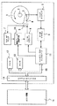
図1は、本発明の一実施の形態であるハードディスク装置の一例を示したブロック図である。本実施の形態のハードディスク装置は、情報が磁気的に記録されるディスク状の磁気記録媒体1と、この磁気記録媒体1を回転駆動するスピンドルモータ2と、磁気記録媒体1に情報を記録する、あるいは記録された情報を読み出す磁気ヘッド3と、磁気ヘッド3を支持するアーム4と、アーム4を駆動するボイスコイルモータ5(アクチュエータ)とを有する。ボイスコイルモータ5の駆動はVCMドライバ6によって行われ、ボイスコイルモータ5の逆起電力はバックemfモニタ7でモニタされる。ヘッド3のアナログ出力はヘッドプリアンプ8で増幅され、サーボチャネル9に入力される。
【0020】
本実施の形態のハードディスク装置では緊急ブレーキ制御手段10を有する。緊急ブレーキ制御手段10については後に詳述する。ハードディスクコントローラ11は、ディスク装置全体を制御するものであり、たとえばサーボチャネル9からのサーボ信号を受けてVCMドライバ6にドライバ信号を出力する。あるいは緊急ブレーキモードに入った時には、緊急ブレーキ制御手段10に制御信号を入力し、緊急ブレーキ制御手段10はバックemfモニタ7からの信号を参照してVCMに緊急ブレーキ駆動をかける。
【0021】
ハードディスクコントローラ11は、RAM12、ROM13、ホストインターフェイス14とバス15を介して接続される。ホストインターフェイス14はホスト装置16とインターフェイスする。ROM13には、ハードディスクコントローラ11内のMPUで処理されるプログラムが格納され、RAM12には、たとえば前記プログラムがROM13からロードされる。あるいはRAM12は、ディスク装置から入力されディスク装置に出力されるデータのバッファとして機能する。
【0022】
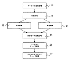
図2は、前記したハードディスクコントローラ11の部分とその周辺の部材をさらに詳しく示したブロック図である。前記した部材あるいは手段のほかに、以下の部材あるいは手段を有する。すなわち、サーボロジック手段17、位置生成手段・加速チェック手段18、入力最適化手段・ハザードチェック手段19、サーボコントローラ20、ディジタルフィルタ21、状態推定器22、MPU23を有する。なお、多くの部材あるいは手段は、1チップの素子としてハードディスクコントローラ11内に構成されるが、これに限られず、ディスクリート素子として構成されてもよい。
【0023】
磁気記録媒体1には、放射状に位置情報が記録されている。位置情報はサーボアドレスマーク(SAM)、グレイコード、バーストからなる。位置情報を含む媒体1上のデータはヘッドにより読み出され、ヘッドプリアンプ8で増幅されてサーボチャネル9に入力される。
【0024】
サーボチャネル9は、ヘッドプリアンプ8のアナログ波形からSAMを検出し、SAMを検出した時にはそのタイミングでsmf(servo address mark found)信号をサーボロジック手段17に送る。また、SAMに続くグレイコードをデコードし、バースト信号をA/D変換する。これらデータはサーボデータラインを介してサーボロジック手段17にシリアル転送される。サーボチャネル9は、サーボゲート信号によりアクティブにされる。
【0025】
サーボロジック手段17は、設計されたサンプリング間隔で媒体1に書込まれたサーボパターン(位置情報)を読み込むために、サーボチャネル9をアクティブにするタイミング制御を行う。サーボチャネル9から得た情報を基に読み込まれた位置情報を生成する。また、位置情報を生成したタイミングでMPU23に対してサーボ割り込みを発生する。同時にサーボロックのステータスを生成する。また、サーボロジック手段17は、サーボチャネルでのSAMの検出状況をモニタし、定められた時間ウィンドウ内でSAMが検出されない時にはダミーSAM生成手段24を用いてダミーSAMを生成する。ダミーSAMを生成するので、サーボチャネルからSAMが検出された場合と同様にMPU23に対してサーボ割り込みを発生することができる。
【0026】
位置生成手段・加速チェック手段18は、サーボロジック手段17からの情報と状態推定手段22からの情報を基に位置情報の誤読を判断する。目標位置を基にフィードバック制御に必要な位置偏差情報を算出する。
【0027】
緊急ブレーキ制御手段10は、サーボパターン(位置情報:SAM)が読めなくなった時に起動される。サーボパターンが読めていた最後の速度を基にヘッド速度が安全な速度(たとえば0.4m/sec)以下まで減速させる。ヘッド速度の減速はVCMドライバ6に一定電流(たとえば1A)を流し続ける。あるいはバックemfからの入力を利用して制御を行う。
【0028】
バックemfモニタ7は、VCMにかかる逆起電力を測定する。この測定値を用いて緊急ブレーキ制御にフィードバックをかけることができる。サーボパターンが見えない時の速度測定の役割をする。
【0029】
入力最適化手段・ハザードチェック手段19は、位置生成手段の出力情報を検査し、入力最適化手段の後段のサーボコントローラ20が不連続な出力を行わないようにする機能を持つ。また、ヘッド位置の読み込み不良が決められた回数以上連続したかどうかを判定し、制御を緊急ブレーキ制御に切り替える。
【0030】
サーボコントローラ20は、シークタイムが最も短くなるように最適化したフィードバック、フィードフォワードの各パラメータを内蔵する。各サンプリング(サーボ割り込み制御)のVCM出力を計算する。ディジタルフィルタ21は、機構系の共振を抑制するノッチフィルタを実装する。
【0031】
状態推定手段22は、その内部にアクチュエータの物理モデルと実験により定めたパラメータとを持ち、実機からの情報をフィードバックしながら次回のサンプリング(サーボ割り込み)におけるヘッド位置を推定する。
【0032】
MPU23は、RAM12あるいはROM13に記録されたマイクロコードに従い各種制御を行う。本実施の形態で特に重要な制御機能として、サーボロジックからの割り込み信号に応じてサーボ制御を行う機能を持つ。
【0033】
なお本実施の形態ではランプ25を有する(ロード/アンロード機構を持つ)ハードディスク装置に本発明を適用する。ロード/アンロード機構では、オーバーランが生じた時に記録媒体への損傷が生じる可能性が高いので、本願発明を適用する効果が大きい。しかし、ロード/アンロード機構は本発明の本質部分ではなく、特に必須の要件ではない。
【0034】
次に、本発明の制御方法について説明する。図3は、SAMの取得からサーボ割り込み制御に至る流れを示したフローチャートである。SAMの取得のためにサーボロジック手段17からサーボチャネル9にサーボゲート信号を送る(ステップ26)。サーボゲートをHighレベルにすることによりサーボチャネルがアクティブになる。サーボゲートをHighレベルにした後、所定の時間枠(SAMカミングウィンドウ)内でsmf信号が得られるかを判断する(ステップ27)。smf信号が得られた場合(SAMが取得できた場合)、そのタイミングでサーボ割り込み信号を発行し、サーボ制御に入る(ステップ28)。ステップ27でsmf信号が得られなかったときにはダミーSAMを生成する(ステップ29)。ダミーSAMは図4に示すように、サーボロックウィンドウ内で生成する。このようにサーボロックウィンドウ内でダミーSAMを生成するため、サーボロックを解除されることがない。また、サーボアンロックと判断されないので次のセクタの読み出しの時には通常どおりサーボゲートが開けられる。このためエラーを発生したセクタについてのみダミーSAMが用いられる。なお、ダミーSAMを用いた場合には、ダミーSAMを生成するかの判断および生成のための時間が必要であり、ダミーSAMを用いないで制御する本来のインターバルと比較してタイミングが遅れる。次回のSAM読み出しの際も本来のタイミングでサーボゲートを開ける必要があるので、セクタインターバルとして本来のインターバルよりも短いダミーインターバルを用いる(ステップ30)。ダミーSAMによりサーボ割り込み信号が生成され、通常の場合と同様にサーボ割り込み制御に入る(ステップ28)。
【0035】
このように、本実施の形態ではSAMが読めなくてもダミーSAMを用いてサーボ割り込み信号を規則的に発行し、サーボ制御を通常どおり規則的に行う。このため、VCMをニュートラルにしてサーボパターン検索モードに入るよりも、状態推定手段22と併せて用いることにより、過去の正しく読めていた状態からの推定によりほぼ正しいトラック位置を維持する確率が高い。突発的な要因によりSAMが読めなくても次回の読み出しの時には読める可能性が高く、正常動作に復帰する可能性が高くなる。
【0036】
なお、本実施の形態の制御方法は高速シーク動作中にダミーSAMを用いることに特徴があり、トラックフォロイング中にダミーSAMを用いる構成とは異なる。トラックフォロイング中のダミーSAMは、マークに損傷があった場合のリカバリに用いられるものであり、本実施の形態のように高速シーク動作中にサーボ制御を維持することを目的にするものではない。
【0037】
図5はサーボ割り込み信号が発行された時の1回のサーボ割り込み制御の概要を示したフローチャートである。まず、MPU23からの指令により、ターゲット変更処理を行う(ステップ31)。ターゲット変更処理は、ホストあるいはMPU23からの指令によりヘッドがフォロイングするべき目標トラックの位置が変更され、サーボ機構がこれを認識する処理である。ターゲットが変更された時にはヘッドの位置移動はターゲットまでのシーク時間を最短にするように最適の動作が選択される。なお、次に説明する位置生成のステップまでの間に、たとえばエラーリカバリ等の各種の処理が行われても良い。
【0038】
次にヘッドの現在位置を生成する位置生成の処理が行われる(ステップ32)。位置生成は、サーボチャネルから得たサーボデータに基づく生の位置データ、あるいは状態推定手段22から得られる推定位置データ等である。生成されるデータにはたとえば、前回の位置データと今回の位置データの差で得られる速度データや、前回の速度データと今回の速度データとの差で得られる加速度データ等が含まれる。また、推定位置データか生の位置データの何れを適用するかは推定値と生データの偏差や動作モードにより選択出来る。
【0039】
次に、現在の制御モードに従い、通常制御(ステップ33)、あるいは緊急制御(ステップ34)の何れかの処理が行われる。制御モードは前回のサーボ割り込み処理の際に決定され、その決定された制御モードが今回適用される。通常制御のモードには、ヘッドが速度コントロール状態にある速度制御モード、目標トラックに収斂しつつある状態の安定モード、目標トラックをフォロウイングしている状態のトラックフォロウイングモード等、目標トラックと現在位置との差に応じた複数段階の制御モードがあっても良い。このように複数段階に分けて制御することにより各モードに応じた最適の制御パラメータを選択でき、制御を最適化できる。なお、緊急制御については後に詳しく述べる。
【0040】
次に、制御モードの変更処理を行う(ステップ35)。このステップは後に詳しく述べる。その後、シーク完了チェック処理を行い(ステップ36)、シークタイムアウトチェック処理を行う(ステップ37)。シーク完了チェック処理は、ヘッドがターゲットのトラックをフォロイングしてリード/ライトが行える状況になったことを検出し通知する処理である。カウンタを用いて、複数回のサーボ割り込み処理でフォロイング状態が確認された後にシーク完了を発行するようにしても良い。シークタイムアウトチェック処理は、所定の時間が経過した後にシーク完了が発行されない時にシークエラーメッセージが発行されて終了する。
【0041】
図6は、制御モードの変更処理(ステップ35)の一例を示したフローチャートである。今、制御モードは通常制御にあると仮定する。当該サーボ割り込み処理において、ダミーSAMが使用されたか否かを判断する(ステップ38)。ダミーSAMが使用された場合にはハザードカウンタを1つ増加し(ステップ39)、ハザードカウンタが5以上であるか否かを判断する(ステップ40)。ここではハザードカウンタの基準値を5としているが変更可能なことは勿論である。ハザードカウンタが5以上の場合には緊急ブレーキモードに変更し(ステップ41)、制御モード変更処理を終了する(ステップ42)。ハザードカウンタが5以上でない場合は、制御モードを変更することなく(つまり通常制御のまま維持する)、制御モード変更処理を終了する(ステップ42)。
【0042】
一方、ダミーSAMが使用されない場合は、グレイコードをミスリードしたか否かを判断する(ステップ43)。なお、グレイコードのミスリードについては後述する。ミスリードした場合にはハザードカウンタの値を維持したまま、かつ、制御モードを変更することなく制御モード変更処理を終了する(ステップ42)。一方ミスリードしていない場合(すなわち、全て順調に動作している場合)は、ハザードカウンタを0にリセット(ステップ44)した後、制御モードを変更することなく制御モード変更処理を終了する(ステップ42)。つまり、SAMが正常に読めており、かつグレイコードのミスリードもない場合には正常に動作しているのだからハザードカウンタは0にリセットされる。SAMが正常に読めている場合であっても、グレイコードのミスリードがある場合には、全くの問題なしとはできないので、現状のハザードカウンタを維持する。SAMが正常に読めない場合は明らかに異常であるからハザードカウンタを増加する。但し、直ちに緊急ブレーキ処理を行うのではなく、ハザードカウンタが所定の値を超えた場合に緊急モードに入る。このような制御方法をとることにより、数回程度のSAMの読み取り不良が発生したとしても、それが偶発的なものであれば、その後正常にサーボパターンが読まれる場合があり、このような場合にはハザードカウンタがリセットされてハザードが顕在化することがない。一方、真に障害がある場合には、規定値を超えるハザードカウンタにより検知され、安全な状態でエラー処理が行えるように緊急ブレーキモードに入ることができる。
【0043】
なお、ここではステップ43でyesと判断された時に、ハザードカウンタの値を変化させないこととしたが、安全側に考えるならダミーSAMの場合と同様にハザードカウンタを増加しても良い。あるいは重みをつけて、たとえばダミーSAM利用の場合には2つ増加し、ミスリードの場合には1つ増加するようにしても良い。
【0044】
図7は緊急ブレーキ処理(ステップ34)の一例を示したフローチャートである。前回のサーボ割り込み処理におけるモード変更処理で、制御モードが緊急制御モードに変更された時には、次回のサーボ割り込み処理ではステップ32の位置生成後に緊急制御(ステップ34)に進む。
【0045】
まず、バックemfモニタ7の出力を取得し(ステップ45)、その値が飽和しているか否かを判断する(ステップ46)。飽和している場合には出力の極性からヘッドの移動方向を把握する(ステップ47)。移動方向に応じてVCMに印加するブレーキ電流の極性を決定し、ブレーキ電流の駆動を行う(ステップ48)。この段階ではヘッドの移動速度は把握できていないので、所定の電流値と印加時間(たとえば絶対値で1A、印加時間を3.2msec)で駆動する。前記所定の値は、少なくともバックemfモニタが飽和する程度の大きな速度を有していることと、VCMおよびアクチュエータの特性とを考慮して決定できる。次に逆方向駆動カウンタ(funsya_count)を1つ減少させ(ステップ49)、逆方向駆動カウンタが0か否かを判断する(ステップ50)。なお、逆方向駆動カウンタの値は、その時の速度値に適当なファクタを掛けて決定できる。逆方向駆動カウンタが0の場合は、所定の減速処理が行われたはずであるからエラーリカバリ処理に入る(ステップ51)。エラーリカバリ処理では、シークエラー報告が発行される。逆方向駆動カウンタが0でない場合は、緊急ブレーキ処理を終了して通常のサーボ割り込み処理に戻る(ステップ52)。このように、本実施の形態の制御方法では、緊急ブレーキ処理の途中でも通常通りサーボ割り込み処理を行ってシーク動作を繰り返す。この途中でサーボパターンが読める場合があり、この場合は緊急ブレーキ処理から抜け出して通常制御処理に復帰することが可能になる。すなわち、本制御方法では、緊急処理に入った後においても正常制御処理への復帰の可能性を残しており、真に復帰不能の場合にのみシークエラーを発行する点に特徴がある。このようなシークエラーの場合にあってもヘッド速度は十分に減速され、クラッシュストップ機構等への衝突が生じたとしても回復不能な程度の障害を生じないようにすることができる。
【0046】
一方、ステップ46で測定回路が飽和していないと判断された時には、バックemf回路の出力値を用いてヘッド位置のフィードバック制御を行う(ステップ53)。所定の制御の後、バックemfの出力値が基準値以下であるかを判断し(ステップ54)、基準値以下である場合には十分にヘッド速度が減速されているのでエラーリカバリ処理に入る(ステップ51)。バックemfの出力値が基準値以上である時には、タイムアウトであるかを判断し(ステップ55)、タイムアウトの時にはエラーリカバリ処理に入る(ステップ51)。タイムアウトでない場合は緊急ブレーキ処理を終了して通常のサーボ割り込み処理に戻る(ステップ52)。バックemf回路の出力値を用いることができる場合は、フィードバック制御が可能なのでより通常制御状態に復帰できる可能性が高くなる。
【0047】
図8はバックemfモニタ7の一例を示した回路図である。VCMモータに流れる電流をセンサRによって電圧に変換し、このセンサRの両端電圧を1段目の増幅器OP1で増幅する。OP1の出力を入力とする2つの増幅器OP2とOP3は、OP2が従来から用いられているロード/アンロード機構用のバックemf回路である。ヘッドがランプからのロード/アンロードされる時にはスイッチSが端子A側に接続されて出力Outが得られる。一方OP3が本実施の形態の制御方法に用いられる回路である。つまりここではロード/アンロード機構用のバックemf回路を一部流用している。OP3の負帰還回路を構成する素子とマイナス入力側に接続される抵抗素子の値を調整して、フルスケールを調整できる。
【0048】
以上説明したように、本実施の形態の制御方法では、サーボパターン(SAM、グレイコード、バースト)が読めなくとも、ダミーSAMを用いてサーボ割り込み処理(サーボ制御処理)を維持する。そして、SAMが読めない状態が所定回数を超えれば緊急ブレーキ処理を行ってシークエラーを発行する。このような制御方法により、偶発的なSAMの読み取り不良が発生しても次回の読み取り時には復帰できる可能性が高くなる。また、緊急ブレーキ処理中でも通常制御に復帰できる可能性があるので、結果としてシークエラーとなる確率が小さくできる。また、シークエラーになる場合であってもヘッド速度を十分に減速した状態でエラー処理されるので、ヘッドのオーバーランとリバウンドによる磁気記録媒体表面の損傷の発生を抑制できる。
【0049】
次に、グレイコードのミスリードを生じた場合の処理について説明する。図9は速度変化モニタ手段での処理の一例を示したフローチャートである。まず、サーボデータから生のシリンダデータ(ヘッド位置)を取得する(ステップ56)。次に、前回のトラック値(ヘッド位置)と現在の生のシリンダデータ(ヘッド位置)の差から現在のヘッド速度を計算する(ステップ57)。次に、前回のヘッド速度と現在のヘッド速度の差から現在のヘッド加速度を計算する(ステップ58)。ヘッド加速度は、一般にアクチュエータの特性等からその上限(絶対値)がほぼ決まっている。ここで、得られた加速度がありえない加速度になっているか否かを判断する(ステップ59)。加速度が正常値の範囲内なら速度変化モニタ処理を終了し(ステップ60)、加速度が正常値の範囲を超えているなら当該シリンダ値を取得したリードはミスリードであったと判断する(ステップ61)、その後速度変化モニタ処理を終了する(ステップ60)。このようなミスリードの情報は前記した制御モードの変更処理で用いられる。
【0050】
次に、異常サーボ入力を防止する処理について説明する。図10は、異常サーボ入力防止処理の一例を示したフローチャートである。まず、状態推定手段からの情報を加味してヘッド位置を取得する(ステップ62)。 現在のヘッド位置をP(n)として表す。次に、前回のヘッド位置P(n−1)を用いて、現在のヘッド速度V(n)を計算する(ステップ63)。 V(n)=P(n)−P(n−1)である。次に、ターゲットトラックまでの距離を入力とする軌道計算関数によりその場所での目標速度TV(n)を計算する(ステップ64)。V(n)とTV(n)とからサーボコントローラの入力値X(n)=V(n)−TV(n)を計算する(ステップ65)。X(n)の絶対値が最大変化値を超えているかを判断し(ステップ66)、最大変化値を超えている場合にはその極性を考慮してX(n)に最大変化値を代入する(ステップ67)。超えていない場合にはX(n)としてそのままの値を用いる。その後VCMコントロール値U(n)の計算を行う(ステップ68)。なお、U(n)=U(n−1)+Y(n)、Y(n)=−k1×X(n)−k2×X(n−1)−k3×Y(n−1)−k4×Y(n−2)、である。k1〜k4は、その時の制御モードごとに適切に選択された定数である。そして、U(n)をディジタルフィルタに入力し、VCMをコントロールする(ステップ69)。
【0051】
このように入力X(n)に制限を設けるので、VCMへの不連続な入力が抑制される。この結果、VCMからの異音の発生や振動の発生が抑制できる。
【0052】
また、異常サーボ入力抑制の他の例を図11に示す。図10と同様にサーボコントローラ入力の計算を行い(ステップ65)、減速過程中かを判断する(ステップ70)。減速過程中の場合は、X(n)が加速の状況にあるかを判断し(ステップ71)、加速の状態にある場合は、X(n)に減速状態になるようなのティピカル値を入力する(ステップ72)。そして通常の制御に戻る(ステップ73)。減速過程中に、ヘッドが加速するような値が入力されるのは異常であるから、入力値をヘッドが減速状態になるような入力値に置き換えるものである。この場合、減速入力値としてティピカル値を選択する。ティピカル値はアクチュエータの特性、VCMの特性等から最も代表的な値として予め実験等により求めた値であり、最適値とはいえないが、この場合の代表値としては妥当な値である。このように異常入力を検出してこれを正常な値に置き換えるため、VCMの制御が滑らかに行われ、異音、振動の発生を抑制できる。
【0053】
さらに、図示はしないが、状態推定手段への入力値として妥当でない値が読み取られ、入力される場合がある、このような場合にも入力値に制限を設けて、状態推定手段の内部状態を良好に維持することができる。
【0054】
以上、本発明者によってなされた発明を発明の実施の形態に基づき具体的に説明したが、本発明は前記実施の形態に限定されるものではなく、その要旨を逸脱しない範囲で種々変更可能である。
【0055】
たとえば、前記実施の形態の制御モード変更処理(図6)のフローでは、ダミーSAMを用いず、かつ、グレイコードのミスリードがない場合(つまり正常にサーボパターンが読めた場合)には、直ちにハザードカウンタを0にリセットする例を説明した。この場合、緊急ブレーキ制御モードにある状態で1度でも正常にサーボパターン(SAM、グレイコード等)が読めれば、通常制御モードに復帰することになる。しかし、一般に緊急ブレーキモードにある状態はヘッド制御が不安定な状態であり、1度の正常なサーボパターンのリードをもって通常制御モードに復帰させるには、偶然に正常なサーボパターンのリードが行われた場合を排除することができない。このため、より安全で確実なヘッド制御処理を行うために、たとえば図12に示すような制御モード変更処理を採用できる。図12は制御モード変更処理の他の例を示したフローチャートである。図12において、ステップ74に示す通常制御リターンカウンタ(Norm_ret_count)を導入できる。緊急ブレーキモード(ステップ41)に入る段階で通常制御リターンカウンタを0にリセットし(ステップ74)、次回のサーボ割り込み処理から緊急ブレーキ制御状態に入る。緊急ブレーキモードにおけるサーボパターンの読み取りで、SAMとグレイコードが正常に読めたと判断(ステップ43でnoの判断)された場合、通常制御リターンカウンタを1つ増加し(ステップ75)、通常制御リターンカウンタが5以上であるかを判断する(ステップ76)。noの場合には、未だ通常制御に戻すには十分でないと判断し、制御モードを緊急ブレーキモードに維持したまま以降のサーボ制御を続ける(ステップ42)。制御リターンカウンタが5以上である場合には、十分に制御状態が安定であると判断できるので制御モードを通常制御モードに設定し(ステップ77)、ハザードカウンタを0にリセットして(ステップ44)、以降のサーボ制御を続ける(ステップ42)。このような制御を採用することにより、緊急ブレーキモードからの通常制御モードへの復帰において、偶発的なサーボパターンの読み取りによる復帰を排除できる。ヘッド制御がほぼ確実に安定した場合にのみ通常制御に戻し、緊急時のイレギュラーな復帰を防止して、意図しないヘッドクラッシュを防止できる。なお、上記例では制御リターンカウンタの基準値を5としたがこれに限られないことは勿論である。
【0056】
また、前記実施の形態では、アーム制御手段としてボイスコイルモータ(VCM)を例示したが、これに限られず、その他のモータ、アクチュエータを用いることも可能である。
【0057】
また、前記実施の形態では回転記憶装置の一例としてハードディスク装置を例示して説明したが、ハードディスク装置に限られず、回転型記録媒体を有する記憶装置、たとえばCD−R/W、DVD、MO記憶装置等書き換え可能な光学的、光学的磁気的記録装置にも適用できる。また、たとえばフロッピィディスク装置等リムーバルな回転型磁気記録装置にも適用が可能である。
【0058】
【発明の効果】
本願で開示される発明のうち、代表的なものによって得られる効果は、以下の通りである。SAMの検出ができない場合であってもサーボロック状態を維持し、正常な読み取り状態に復帰することができる。SAMの正常な検出が望めないと判断した場合には、ヘッドのクラッシュストップへの衝突を回避し、あるいは媒体表面への回復不能な損傷が生じない程度の衝突に止める手法を提供できる。好ましくないVCMの異音、あるいは振動の発生を抑制できる。
【図面の簡単な説明】
【図1】本発明の一実施の形態であるハードディスク装置の一例を示したブロック図である。
【図2】ハードディスクコントローラとその周辺部をさらに詳しく示したブロック図である。
【図3】SAMの取得からサーボ割り込み制御に至る流れを示したフローチャートである。
【図4】ダミーSAMを生成するタイミングを示す図である。
【図5】サーボ割り込み信号が発行された時の1回のサーボ割り込み制御の概要を示したフローチャートである。
【図6】制御モードの変更処理の一例を示したフローチャートである。
【図7】緊急ブレーキ処理の一例を示したフローチャートである。
【図8】バックemfモニタの一例を示した回路図である。
【図9】速度変化モニタ手段での処理の一例を示したフローチャートである。
【図10】異常サーボ入力防止処理の一例を示したフローチャートである。
【図11】異常サーボ入力防止処理の他の例を示したフローチャートである。
【図12】制御モード変更処理の他の例を示したフローチャートである。
【符号の説明】
1…磁気記録媒体、2…スピンドルモータ、3…磁気ヘッド、4…アーム、5…ボイスコイルモータ、6…VCMドライバ、7…バックemfモニタ、8…ヘッドプリアンプ、9…サーボチャネル、10…緊急ブレーキ制御手段、11…ハードディスクコントローラ、12…RAM、13…ROM、14…ホストインターフェイス、15…バス、16…ホスト装置、17…サーボロジック手段、18…位置生成手段・加速チェック手段、19…入力最適化手段・ハザードチェック手段、20…サーボコントローラ、21…ディジタルフィルタ、22…状態推定手段、23…MPU、24…ダミーSAM生成手段、25…ランプロード機構、A…端子、OP1〜OP3…増幅器、Out…出力。[0001]
BACKGROUND OF THE INVENTION
The present invention relates to a rotary storage device and a control method therefor, and more particularly to a technique that is effective when applied to improvement in reliability during high-speed seek operation of a hard disk device.
[0002]
[Prior art]
Generally, a hard disk device uses servo means for head positioning. In a hard disk device, position information is recorded (written) on a disk medium in advance, and the current head position is detected by reading this position information with a head. The position information is recorded radially on the disk medium and is periodically detected within the range of rotation accuracy of the disk medium. The position information generally comprises a servo address mark (SAM), gray code, and burst data, and a servo lock state is realized by periodic detection of the SAM. In general, in the servo lock state, the address information in the Gray code following the SAM can be read to detect the head track position (cylinder position).
[0003]
The movement of the head arm is controlled by an actuator, and usually a voice coil motor (VCM) is used. The movement of the head to the target address is obtained by trajectory calculation from the read current address and target address information. The input current to the VCM is controlled so that the head reaches the target address in the shortest time. In general, hard disk drives are designed to maximize their performance, and in order to make the seek time as short as possible, the maximum speed of the head tip is 3.3 m during high-speed seek operations before moving to the target address. / Sec.
[0004]
In recent years, the recording density of hard disk devices has been improved, and operation in more severe conditions has been realized. For this reason, the probability of causing an error in reading the position information increases. Position information reading errors are caused by a variety of factors such as temperature, stress conditions in the external environment such as a power supply, imperfect writing of position information, and temporary head failure. Since it is practically difficult to eliminate these factors, an error recovery method is important. In particular, in recent years, a load / unload mechanism (sometimes referred to as a ramp load mechanism) is increasingly employed from the viewpoint of improving impact resistance and preventing head wear. In the load / unload mechanism, since the head rides on the ramp and stands by, the head position becomes higher than the state of flying on the rotating disk. For this reason, when a seek error occurs and the head overruns the ramp at a high speed (for example, 1 m / sec or more), the head collides with a crash stop mechanism located on the outer periphery thereof. There is a case in which the magnetic medium surface is damaged by rebound of the head due to the collision.
[0005]
Normally, when the SAM cannot be read, the servo lock state is released and the servo is unlocked. In this case, an attempt is made to read the SAM with the VCM output set to neutral. Since the VCM is neutral, the head arm will make an inertial movement. When reading of the gray code fails or when a valid gray code cannot be read, a gray code misread is detected using a state estimator. The state estimator has a physical model for the state variable to be controlled and a measured value (experimental value) in the actual machine, and estimates using the difference (estimated error) between the measured value (read gray code) and the estimated value. Has a function to correct the value. Since the output (estimated value) of the estimator whose state is stable is considered to have sufficient reliability, the estimated value is adopted when a difference between the measured value and a preset reference value is detected. . In this way, gray code misleads can be detected and corrected.
[0006]
Japanese Patent Laid-Open No. 9-139034 describes a recovery technique when a servo error occurs during high-speed seek. In the technique of the publication, when the estimated speed exceeds the reference speed, the drive current is immediately stopped, a brake current according to the difference between the estimated speed and the reference speed is supplied, and the head speed is reduced to a predetermined speed or less. A technique for causing a collision with the stopper later is described.
[0007]
Japanese Patent Application Laid-Open No. 11-45522 describes a technique of integrating a drive current from the start of seeking with a integrator at the time of a seek error and generating a deceleration control signal based on the integrated value.
[0008]
Japanese Patent Application Laid-Open No. 6-1887749 describes a technique for controlling the head to decelerate by switching from a normal speed control signal to a deceleration signal recorded in advance in a storage circuit when a seek error occurs. Japanese Patent Application Laid-Open No. 4-106768 discloses a technique for performing speed control using a normal speed table in a normal state and decelerating using an abnormal speed table in a normal state.
[0009]
[Problems to be solved by the invention]
However, the above-described conventional technology does not provide a sufficient countermeasure against seek errors. In the measure to make the VCM neutral, if the inertial velocity at that time exceeds 1 m / sec, and the SAM cannot be read, the above-described problem of causing permanent damage to the medium surface. There is. Even if the SAM can be read, there is no guarantee that the remaining area can be sufficiently decelerated.
[0010]
On the other hand, in the case of a gray code misread, the application of the state estimator is effective when the error rate is low. However, if a higher density recording is to be realized, there is a problem that the error rate inevitably increases and does not function sufficiently. In particular, if the estimator deviates from the actual head position, the estimated value may be used to cause unexpected head acceleration, and the estimator will determine that the actual machine is correct and its own value. If a gray code misread occurs during a transition period that goes to the actual machine, unexpected head acceleration may occur. These unexpected accelerations increase the risk of head overrun, as well as generating sound and vibration due to discontinuous VCM output.
[0011]
The objects of the present invention are as follows. An object of the present invention is to provide a method of trying to maintain a servo lock state and return to a normal reading state even when SAM cannot be detected. In the case where it is determined that normal detection of SAM cannot be expected, there is provided a technique for avoiding the collision of the head with the crash stop or stopping the collision to such a degree that irreparable damage to the medium surface does not occur. . Another object of the present invention is to provide a technique for suppressing the generation of undesirable VCM noise or vibration.
[0012]
[Means for Solving the Problems]
The outline of the present invention will be described as follows. That is, according to the present invention, even when the SAM cannot be detected for some reason, the dummy SAM is generated at a timing when the servo lock is not released. As a result, regular servo interrupt control can be executed to attempt to return to a normal reading state. Whether or not the SAM has been read can be determined by whether or not a signal (smf) in which the SAM has been read is output within a time window (SAM coming window) in which the SAM should be read. When the dummy SAM is generated, the dummy sector interval is used as the sector interval so as not to cause a delay of the next servo gate.
[0013]
Thus, even if the SAM cannot be read, the dummy SAM is generated and the servo interrupt control is performed as usual, but the normal state cannot be restored even after a certain number of intervals (time) (the SAM cannot be read yet). In case, emergency brake control is entered. In the emergency brake control, the moving direction of the head provided at the tip of the arm is determined, and the current of the VCM is driven so that the arm is driven in the reverse direction. In this case, the drive current value and the drive time are determined in advance. Alternatively, feedback control can be performed using an output value of a back emf (Back Electromotive Force) circuit used in the load / unload mechanism. Since braking is applied to the movement of the head, even if the head collides with the crash stop mechanism, the head collides in a sufficiently decelerated state, so that problems such as data loss due to damage to the surface of the magnetic medium can be avoided.
[0014]
In the present invention, even when emergency brake control is entered, SAM detection and gray code reading are still attempted. Such a trial is possible because the dummy interrupt SAM is generated periodically, and the servo interrupt control is normally performed. When SAM is detected during emergency brake control, it is possible to return to normal control.
[0015]
Further, the present invention proposes the following measures against gray code misleading. That is, if the gray code is misread, an acceleration value and an input value to the servo controller that cannot be obtained from the previous track position are obtained. Alternatively, a value far from the estimated value estimated by the state estimator is read. When such an impossible acceleration value and input value are obtained, the control can be continued by replacing it with a predetermined maximum value. When the impossible value continues for a certain period of time, it can be determined that the servo control is not normally performed and the emergency brake control can be started. Alternatively, it is possible not to reset a hazard counter that is a counter for entering emergency brake control when a mislead occurs.
[0016]
Note that the input of an input value to be accelerated when the head is in the deceleration process can also be considered as a gray code misread. In this case, the head is decelerated, and the input value is replaced with a typical value, and control can be continued. As a result, a more probable value is used, and servo control close to optimum can be performed.
[0017]
These gray code misleading measures are all converted to input values that suppress discontinuous current input (power application) to the VCM. As a result, generation of sound and vibration from the VCM are suppressed. Can be suppressed.
[0018]
DETAILED DESCRIPTION OF THE INVENTION
Hereinafter, embodiments of the present invention will be described in detail with reference to the drawings. However, the present invention can be implemented in many different modes and should not be interpreted as being limited to the description of the present embodiment. Note that the same numbers are assigned to the same elements throughout the embodiment.
[0019]
FIG. 1 is a block diagram showing an example of a hard disk device according to an embodiment of the present invention. The hard disk device of the present embodiment records information on a disk-shaped
[0020]
The hard disk device of the present embodiment has emergency brake control means 10. The emergency brake control means 10 will be described in detail later. The hard disk controller 11 controls the entire disk device. For example, the hard disk controller 11 receives a servo signal from the
[0021]
The hard disk controller 11 is connected to the
[0022]
FIG. 2 is a block diagram showing in more detail the hard disk controller 11 and its peripheral members. In addition to the members or means described above, the following members or means are provided. That is, it has servo logic means 17, position generation means / acceleration check means 18, input optimization means / hazard check means 19,
[0023]
The
[0024]
The
[0025]
The servo logic means 17 performs timing control for activating the
[0026]
The position generation unit /
[0027]
The emergency brake control means 10 is activated when the servo pattern (position information: SAM) cannot be read. Based on the last speed at which the servo pattern has been read, the head speed is reduced to a safe speed (eg, 0.4 m / sec) or less. When the head speed is reduced, a constant current (for example, 1 A) is continuously supplied to the
[0028]
The back emf monitor 7 measures the counter electromotive force applied to the VCM. This measured value can be used to provide feedback for emergency brake control. Serves as a speed measurement when the servo pattern is not visible.
[0029]
The input optimization unit /
[0030]
The
[0031]
The state estimating means 22 has a physical model of the actuator and parameters determined by experiments therein, and estimates the head position at the next sampling (servo interrupt) while feeding back information from the actual machine.
[0032]
The
[0033]
In the present embodiment, the present invention is applied to a hard disk device having a lamp 25 (having a load / unload mechanism). In the load / unload mechanism, there is a high possibility that damage to the recording medium will occur when overrun occurs, so the effect of applying the present invention is great. However, the load / unload mechanism is not an essential part of the present invention and is not a particularly essential requirement.
[0034]
Next, the control method of the present invention will be described. FIG. 3 is a flowchart showing a flow from SAM acquisition to servo interrupt control. A servo gate signal is sent from the servo logic means 17 to the
[0035]
Thus, in this embodiment, even if the SAM cannot be read, the servo interrupt signal is regularly issued using the dummy SAM, and the servo control is regularly performed as usual. For this reason, rather than entering the servo pattern search mode with the VCM set to neutral, there is a higher probability of maintaining a substantially correct track position by estimation from the past correctly read state by using it together with the state estimation means 22. Even if the SAM cannot be read due to a sudden factor, it is highly likely to be read at the next reading, and the possibility of returning to normal operation is high.
[0036]
The control method according to the present embodiment is characterized in that a dummy SAM is used during a high-speed seek operation, and is different from a configuration in which a dummy SAM is used during track following. The dummy SAM during track following is used for recovery when the mark is damaged, and is not intended to maintain servo control during high-speed seek operation as in the present embodiment. .
[0037]
FIG. 5 is a flowchart showing an outline of one-time servo interrupt control when a servo interrupt signal is issued. First, a target change process is performed according to a command from the MPU 23 (step 31). The target change process is a process in which the servo mechanism recognizes the position of the target track to be followed by the head according to a command from the host or the
[0038]
Next, position generation processing for generating the current position of the head is performed (step 32). The position generation is raw position data based on the servo data obtained from the servo channel, estimated position data obtained from the state estimating means 22, or the like. The generated data includes, for example, speed data obtained from the difference between the previous position data and the current position data, acceleration data obtained from the difference between the previous speed data and the current speed data, and the like. Whether to apply the estimated position data or the raw position data can be selected according to the deviation between the estimated value and the raw data and the operation mode.
[0039]
Next, either normal control (step 33) or emergency control (step 34) is performed according to the current control mode. The control mode is determined in the previous servo interrupt process, and the determined control mode is applied this time. The normal control modes include the speed control mode in which the head is in the speed control state, the stable mode in which the head is converging on the target track, the track following mode in which the target track is followed, and the current track and the current track. There may be a multi-step control mode corresponding to the difference from the position. By performing control in a plurality of stages in this way, it is possible to select optimal control parameters according to each mode, and it is possible to optimize control. The emergency control will be described in detail later.
[0040]
Next, control mode change processing is performed (step 35). This step will be described in detail later. Thereafter, seek completion check processing is performed (step 36), and seek timeout check processing is performed (step 37). The seek completion check process is a process for detecting and notifying that the head is ready to read / write by following the target track. A counter may be used to issue a seek completion after the following state is confirmed by a plurality of servo interrupt processes. The seek timeout check process is terminated when a seek error message is issued when a seek completion is not issued after a predetermined time has elapsed.
[0041]
FIG. 6 is a flowchart showing an example of the control mode changing process (step 35). Now assume that the control mode is in normal control. In the servo interrupt process, it is determined whether or not a dummy SAM is used (step 38). If a dummy SAM is used, the hazard counter is incremented by 1 (step 39), and it is determined whether the hazard counter is 5 or more (step 40). Here, the reference value of the hazard counter is set to 5, but it is of course possible to change it. If the hazard counter is 5 or more, the emergency brake mode is changed (step 41), and the control mode change process is terminated (step 42). If the hazard counter is not 5 or more, the control mode changing process is terminated (step 42) without changing the control mode (that is, maintaining the normal control).
[0042]
On the other hand, if the dummy SAM is not used, it is determined whether or not the gray code is misread (step 43). Gray code misread will be described later. When misreading is performed, the control mode changing process is terminated without changing the control mode while maintaining the value of the hazard counter (step 42). On the other hand, if there is no misread (that is, if all are operating smoothly), the hazard counter is reset to 0 (step 44), and then the control mode change process is terminated without changing the control mode (step 42). ). That is, when the SAM is normally read and there is no gray code misread, the hazard counter is reset to 0 because it is operating normally. Even if the SAM can be read normally, if there is a gray code misread, it is impossible to have no problem at all, so the current hazard counter is maintained. If the SAM cannot be read normally, the hazard counter is increased because it is clearly abnormal. However, the emergency brake process is not performed immediately, but the emergency mode is entered when the hazard counter exceeds a predetermined value. By adopting such a control method, even if SAM reading failure occurs several times, if it is accidental, the servo pattern may be read normally after that. In this case, the hazard counter is not reset and the hazard does not become apparent. On the other hand, when there is a true fault, it is detected by a hazard counter exceeding a specified value, and the emergency brake mode can be entered so that error processing can be performed in a safe state.
[0043]
Here, when it is determined yes in
[0044]
FIG. 7 is a flowchart showing an example of the emergency brake process (step 34). When the control mode is changed to the emergency control mode in the mode change process in the previous servo interrupt process, the next servo interrupt process proceeds to the emergency control (step 34) after the position generation in
[0045]
First, the output of the
[0046]
On the other hand, when it is determined in
[0047]
FIG. 8 is a circuit diagram showing an example of the
[0048]
As described above, in the control method of the present embodiment, the servo interrupt process (servo control process) is maintained using the dummy SAM even if the servo pattern (SAM, Gray code, burst) cannot be read. Then, if the state where the SAM cannot be read exceeds a predetermined number of times, an emergency brake process is performed and a seek error is issued. By such a control method, even if an accidental SAM reading failure occurs, there is a high possibility that it can be restored at the next reading. Moreover, since there is a possibility that the normal control can be restored even during the emergency brake process, the probability of a seek error as a result can be reduced. Further, even when a seek error occurs, error processing is performed with the head speed sufficiently reduced, so that occurrence of damage to the surface of the magnetic recording medium due to head overrun and rebound can be suppressed.
[0049]
Next, processing when a gray code misread occurs will be described. FIG. 9 is a flowchart showing an example of processing in the speed change monitoring means. First, raw cylinder data (head position) is acquired from the servo data (step 56). Next, the current head speed is calculated from the difference between the previous track value (head position) and the current raw cylinder data (head position) (step 57). Next, the current head acceleration is calculated from the difference between the previous head speed and the current head speed (step 58). The upper limit (absolute value) of the head acceleration is generally determined from the characteristics of the actuator. Here, it is determined whether or not the obtained acceleration is an impossible acceleration (step 59). If the acceleration is within the normal value range, the speed change monitoring process is terminated (step 60). If the acceleration exceeds the normal value range, it is determined that the lead having acquired the cylinder value is a misread (step 61). Thereafter, the speed change monitoring process is terminated (step 60). Such misread information is used in the control mode changing process described above.
[0050]
Next, processing for preventing abnormal servo input will be described. FIG. 10 is a flowchart showing an example of the abnormal servo input prevention process. First, the head position is acquired in consideration of information from the state estimating means (step 62). The current head position is represented as P (n). Next, the current head speed V (n) is calculated using the previous head position P (n-1) (step 63). V (n) = P (n) -P (n-1). Next, a target speed TV (n) at that location is calculated by a trajectory calculation function that receives the distance to the target track (step 64). The servo controller input value X (n) = V (n) −TV (n) is calculated from V (n) and TV (n) (step 65). It is determined whether the absolute value of X (n) exceeds the maximum change value (step 66). If the maximum change value is exceeded, the maximum change value is substituted into X (n) in consideration of the polarity. (Step 67). When it does not exceed, the same value is used as X (n). Thereafter, the VCM control value U (n) is calculated (step 68). U (n) = U (n-1) + Y (n), Y (n) =-k1 * X (n) -k2 * X (n-1) -k3 * Y (n-1) -k4 × Y (n−2). k1 to k4 are constants appropriately selected for each control mode. Then, U (n) is input to the digital filter and the VCM is controlled (step 69).
[0051]
Since the input X (n) is thus limited, discontinuous input to the VCM is suppressed. As a result, the generation of abnormal noise and vibration from the VCM can be suppressed.
[0052]
Another example of abnormal servo input suppression is shown in FIG. The servo controller input is calculated in the same manner as in FIG. 10 (step 65), and it is determined whether the deceleration process is in progress (step 70). When the vehicle is decelerating, it is determined whether X (n) is in an acceleration state (step 71), and when it is in an acceleration state, a typical value is input to X (n) so that the vehicle is in a deceleration state. (Step 72). Then, the normal control is returned (step 73). During the deceleration process, it is abnormal that a value for accelerating the head is input. Therefore, the input value is replaced with an input value for decelerating the head. In this case, a typical value is selected as the deceleration input value. The typical value is a value that is obtained in advance through experiments or the like as the most representative value from the characteristics of the actuator, the VCM, and the like, and is not an optimum value, but is a reasonable value as a representative value in this case. Since abnormal input is detected and replaced with a normal value in this way, the VCM is controlled smoothly, and the generation of abnormal noise and vibration can be suppressed.
[0053]
Further, although not shown in the figure, an invalid value may be read and input as an input value to the state estimating means. In such a case, the input value is limited, and the internal state of the state estimating means is set. It can be maintained well.
[0054]
As mentioned above, the invention made by the present inventor has been specifically described based on the embodiments of the invention. However, the present invention is not limited to the above-described embodiments, and various modifications can be made without departing from the scope of the invention. is there.
[0055]
For example, in the flow of the control mode change process (FIG. 6) of the above embodiment, if a dummy SAM is not used and there is no gray code misread (that is, the servo pattern can be read normally), a hazard is immediately generated. An example in which the counter is reset to 0 has been described. In this case, if the servo pattern (SAM, gray code, etc.) can be read normally even once in the emergency brake control mode, the normal control mode is restored. However, in general, the emergency brake mode is an unstable head control. To return to the normal control mode with one normal servo pattern read, the normal servo pattern is read accidentally. The case cannot be excluded. For this reason, in order to perform a safer and more reliable head control process, for example, a control mode change process as shown in FIG. 12 can be employed. FIG. 12 is a flowchart showing another example of the control mode change process. In FIG. 12, a normal control return counter (Norm_ret_count) shown in
[0056]
In the above embodiment, the voice coil motor (VCM) is exemplified as the arm control means. However, the present invention is not limited to this, and other motors and actuators can also be used.
[0057]
In the above-described embodiment, the hard disk device is illustrated as an example of the rotary storage device. However, the present invention is not limited to the hard disk device, but a storage device having a rotary recording medium, such as a CD-R / W, DVD, or MO storage device. The present invention can also be applied to optically and optically magnetic recording devices that are rewritable. The present invention can also be applied to a removable rotary magnetic recording device such as a floppy disk device.
[0058]
【The invention's effect】
Among the inventions disclosed in the present application, effects obtained by typical ones are as follows. Even when the SAM cannot be detected, the servo lock state can be maintained and the normal reading state can be restored. When it is determined that normal detection of the SAM cannot be expected, it is possible to provide a technique for avoiding the collision of the head with the crash stop or stopping the collision to such an extent that irreparable damage to the medium surface does not occur. Unwanted VCM noise or vibration can be suppressed.
[Brief description of the drawings]
FIG. 1 is a block diagram showing an example of a hard disk device according to an embodiment of the present invention.
FIG. 2 is a block diagram showing the hard disk controller and its peripheral part in more detail.
FIG. 3 is a flowchart showing a flow from SAM acquisition to servo interrupt control.
FIG. 4 is a diagram illustrating timing for generating a dummy SAM.
FIG. 5 is a flowchart showing an outline of one-time servo interrupt control when a servo interrupt signal is issued.
FIG. 6 is a flowchart showing an example of control mode change processing;
FIG. 7 is a flowchart showing an example of emergency brake processing.
FIG. 8 is a circuit diagram showing an example of a back emf monitor.
FIG. 9 is a flowchart showing an example of processing in a speed change monitoring unit.
FIG. 10 is a flowchart showing an example of an abnormal servo input prevention process.
FIG. 11 is a flowchart showing another example of an abnormal servo input prevention process.
FIG. 12 is a flowchart showing another example of the control mode change process.
[Explanation of symbols]
DESCRIPTION OF
Claims (17)
前記ヘッドから前記位置情報のマーカ信号を読み取る手段と、
マーカ信号読取不成功に応答して、ダミーマーカ信号を生成する手段と、
前記マーカ信号またはダミーマーカ信号の受信に応答して、割り込み処理を実行する手段と、
前記ダミーマーカ信号をカウントすることにより、前記割り込み処理をカウントする手段と、
前記カウント値が所定の値を超えたかを判断する手段と、
前記読み取り/書き込み構造駆動手段からの出力値を計測し、前記出力値から前記読み取り/書き込み構造の移動方向を判断する手段と、
前記カウント数が所定の値を超えた場合に、前記読み取り/書き込み構造駆動手段に対して前記読み取り/書き込み構造の移動方向とは逆方向の駆動力を与える手段と、
前記ヘッドの加速度を判断する手段と、
前記位置情報のアドレス情報をミスリードしたときに、前記加速度が所定の値を越えたかを判断する手段と、を有し、
前記アドレス情報のミスリードと判断された時には、前記割り込み処理中に前記カウント手段をリセットしない記憶装置。A storage medium including position information; medium driving means for driving the storage medium; a read / write structure having a head coupled to an arm; and a read / write structure driving means for driving the read / write structure. A storage device,
Means for reading a marker signal of the position information from the head;
Means for generating a dummy marker signal in response to unsuccessful marker signal reading;
Means for executing interrupt processing in response to reception of the marker signal or dummy marker signal;
Means for counting the interrupt processing by counting the dummy marker signal;
Means for determining whether the count value exceeds a predetermined value;
Means for measuring an output value from the read / write structure driving means and judging a moving direction of the read / write structure from the output value;
Means for applying a driving force in a direction opposite to the moving direction of the read / write structure to the read / write structure driving means when the count exceeds a predetermined value;
Means for determining the acceleration of the head;
Means for determining whether the acceleration exceeds a predetermined value when the address information of the position information is misread,
A storage device that does not reset the counting means during the interrupt processing when it is determined that the address information is misread .
前記ヘッドから前記位置情報のマーカ信号を読み取る手段と、
マーカ信号読取不成功に応答して、ダミーマーカ信号を生成する手段と、
前記マーカ信号またはダミーマーカ信号の受信に応答して、割り込み処理を実行する手段と、
前記ダミーマーカ信号をカウントすることにより、前記割り込み処理をカウントする手段と、
前記カウント値が所定の値を超えたかを判断する手段と、
前記読み取り/書き込み構造駆動手段からの出力値を計測し、前記出力値から前記読み取り/書き込み構造の移動方向を判断する手段と、
前記カウント数が所定の値を超えた場合に、前記読み取り/書き込み構造駆動手段に対して前記読み取り/書き込み構造の移動方向とは逆方向の駆動力を与える手段と、
前記ヘッドの現在位置を推定する状態推定手段と、
前記ヘッドで読み取られた現在のヘッド位置からの偏差が所定の値を超えている場合には、前記推定値をヘッド位置として指定する手段と、
前記状態推定手段への補正入力が所定の値を超えている時には、前記アドレス情報をミスリードしたと判断する手段と、を有し、
前記アドレス情報のミスリードが発生した時には、前記読み取り/書き込み構造駆動手段の前記割り込み処理の間、前記ダミーマーカ信号をカウントすることによって前記割り込み処理をカウントする手段をリセットしない記憶装置。 A storage medium including position information; medium driving means for driving the storage medium; a read / write structure having a head coupled to an arm; and a read / write structure driving means for driving the read / write structure. A storage device,
Means for reading a marker signal of the position information from the head;
Means for generating a dummy marker signal in response to unsuccessful marker signal reading;
Means for executing interrupt processing in response to reception of the marker signal or dummy marker signal;
Means for counting the interrupt processing by counting the dummy marker signal;
Means for determining whether the count value exceeds a predetermined value;
Means for measuring an output value from the read / write structure driving means and judging a moving direction of the read / write structure from the output value;
Means for applying a driving force in a direction opposite to the moving direction of the read / write structure to the read / write structure driving means when the count exceeds a predetermined value;
State estimating means for estimating the current position of the head;
Means for designating the estimated value as a head position when a deviation from a current head position read by the head exceeds a predetermined value;
Means for determining that the address information has been misread when the correction input to the state estimation means exceeds a predetermined value;
A storage device that does not reset the means for counting the interrupt processing by counting the dummy marker signal during the interrupt processing of the read / write structure driving means when a misread of the address information occurs .
前記入力値計算手段は、前記入力値を所定の範囲に制限する請求項1記載の記憶装置。 Means for calculating an input value to the read / write structure driving means from the address information of the position information read by the head and the address information in the previous interrupt processing of the read / write structure driving means; Have
The input value calculating means, storage device according to claim 1, wherein limiting the input value to a predetermined range.
前記ヘッドが前記読み取り/書き込み構造駆動手段により減速されているかを判断し、前記ヘッドが前記読み取り/書き込み構造駆動手段により減速されていると判断され、かつ、前記入力値が加速入力値であるとき、前記加速入力値を前記入力値計算手段により計算された減速入力値に置き換える手段と、
をさらに有する請求項1記載の記憶装置。Means for calculating an input value to the read / write structure driving means from address information of the position information read by the head and address information in the previous interrupt processing of the read / write structure driving means;
When the head is decelerated by the read / write structure driving means, it is determined that the head is decelerated by the read / write structure driving means, and the input value is an acceleration input value Means for replacing the acceleration input value with a deceleration input value calculated by the input value calculation means;
The storage device according to claim 1 , further comprising:
前記ヘッドから前記位置情報のマーカ信号を読み取るステップと、 Reading a marker signal of the position information from the head;
マーカ信号読取不成功に応答して、ダミーマーカ信号を生成するステップと、 Generating a dummy marker signal in response to unsuccessful marker signal reading;
前記マーカ信号またはダミーマーカ信号の受信に応答して、前記読み取り/書き込み構造駆動手段の割り込み処理を実行するステップと、 In response to receiving the marker signal or dummy marker signal, executing interrupt processing of the read / write structure driving means;
前記ダミーマーカ信号をカウントすることにより、前記割り込み処理をカウントするステップと、 Counting the interrupt processing by counting the dummy marker signal;
前記カウント値が所定の値を超えたかを判断するステップと、 Determining whether the count value exceeds a predetermined value;
前記読み取り/書き込み構造駆動手段からの出力値を計測し、前記出力値から前記読み取り/書き込み構造の移動方向を判断するステップと、 Measuring an output value from the read / write structure driving means and determining a moving direction of the read / write structure from the output value;
前記カウント数が所定の値を超えた場合に、前記読み取り/書き込み構造駆動手段に対して前記読み取り/書き込み構造の移動方向とは逆方向の駆動力を与えるステップと、 Applying a driving force in a direction opposite to the moving direction of the read / write structure to the read / write structure driving means when the count exceeds a predetermined value;
前記ヘッドの加速度を判断するステップと、 Determining the acceleration of the head;
前記位置情報のアドレス情報をミスリードしたときに、前記加速度が所定の値を越えたかを判断するステップと、を有し、 Determining whether the acceleration exceeds a predetermined value when misreading the address information of the position information, and
前記アドレス情報のミスリードと判断された時には、前記割り込み処理中に前記ダミーマーカ信号をカウントすることによりカウントした前記割り込み処理のカウント値をリセットしない記憶装置の制御方法。 A control method for a storage device that does not reset the count value of the interrupt processing counted by counting the dummy marker signal during the interrupt processing when it is determined that the address information is misread.
フィードバックループ内の前記出力値を用いて前記駆動力を制御するステップと、
をさらに有する請求項11記載の記憶装置の制御方法。 Monitoring the back electromotive force;
Controlling the driving force using the output value in a feedback loop;
The method for controlling a storage device according to claim 11 , further comprising:
カウント手段のアドレス情報のミスリードの回数が所定の値を超えたことの判断に応答して、前記読み取り/書き込み構造駆動手段に対して前記読み取り/書き込み構造の移動方向とは逆方向の駆動力を与えるステップと、
をさらに有する請求項10記載の記憶装置の制御方法。 Counting the number of miss reads of the address information;
In response to the determination that the number of misreads in the address information of the counting means exceeds a predetermined value, the driving force in the direction opposite to the moving direction of the reading / writing structure is applied to the reading / writing structure driving means. comprising the steps of: Ru given,
The method of claim 1 0, wherein the memory device further comprises a.
前記ヘッドから前記位置情報のマーカ信号を読み取るステップと、
マーカ信号読取不成功に応答して、ダミーマーカ信号を生成するステップと、
前記マーカ信号またはダミーマーカ信号の受信に応答して、前記読み取り/書き込み構造駆動手段の割り込み処理を実行するステップと、
前記ダミーマーカ信号をカウントすることにより、前記割り込み処理をカウントするステップと、
前記カウント値が所定の値を超えたかを判断するステップと、
前記読み取り/書き込み構造駆動手段からの出力値を計測し、前記出力値から前記読み取り/書き込み構造の移動方向を判断するステップと、
前記カウント数が所定の値を超えた場合に、前記読み取り/書き込み構造駆動手段に対して前記読み取り/書き込み構造の移動方向とは逆方向の駆動力を与えるステップと、
前記ヘッドの現在位置を推定するステップと、
前記ヘッドで読み取られた現在のヘッド位置からの偏差が所定の値を超えている場合には、前記推定値をヘッド位置として指定するステップと、
状態推定手段への補正入力が所定の値を超えている時には、アドレス情報をミスリードしたと判断するステップと、を有し、
前記アドレス情報のミスリードが発生した時には、前記読み取り/書き込み構造駆動手段の前記割り込み処理の間、前記アドレス情報のミスリードのカウント手段をリセットしない記憶装置の制御方法。 A storage medium including position information; medium driving means for driving the storage medium; a read / write structure having a head coupled to an arm; and a read / write structure driving means for driving the read / write structure. A storage device control method comprising:
Reading a marker signal of the position information from the head;
Generating a dummy marker signal in response to unsuccessful marker signal reading;
In response to receiving the marker signal or dummy marker signal, executing interrupt processing of the read / write structure driving means;
Counting the interrupt processing by counting the dummy marker signal;
Determining whether the count value exceeds a predetermined value;
Measuring an output value from the read / write structure driving means and determining a moving direction of the read / write structure from the output value;
Applying a driving force in a direction opposite to the moving direction of the read / write structure to the read / write structure driving means when the count exceeds a predetermined value;
Estimating a current position of the head;
Designating the estimated value as a head position if the deviation from the current head position read by the head exceeds a predetermined value;
Determining that the address information has been misread when the correction input to the state estimation means exceeds a predetermined value,
A method for controlling a storage device , wherein the address information miss read counting means is not reset during the interrupt processing of the read / write structure driving means when the address information miss read occurs .
カウント手段のアドレス情報のミスリードの回数が所定の値を超えたことの判断に応答して、前記読み取り/書き込み構造駆動手段に対して前記読み取り/書き込み構造の移動方向とは逆方向の駆動力を与えるステップと、
をさらに有する請求項14記載の記憶装置の制御方法。Counting the number of miss reads of the address information;
In response to the determination that the number of misreads in the address information of the counting means exceeds a predetermined value, the driving force in the direction opposite to the moving direction of the reading / writing structure is applied to the reading / writing structure driving means. Giving step,
15. The storage device control method according to claim 14, further comprising:
をさらに有する請求項10記載の記憶装置の制御方法。 Input limited to a predetermined range from the address information of the position information read by the head and the address information in the previous interrupt processing of the read / write structure drive means to the read / write structure drive means Calculating a value;
The method of claim 1 0, wherein the memory device further comprises a.
前記ヘッドが前記読み取り/書き込み構造駆動手段により減速されているかを判断する ステップと、
前記ヘッドが前記読み取り/書き込み構造駆動手段により減速されていると判断され、かつ、前記入力値が加速入力値であるとき、前記加速入力値を入力値計算手段により計算された減速入力値に置き換えるステップと、
をさらに有する請求項10記載の記憶装置の制御方法。 Calculating an input value to the read / write structure driving means from the address information of the position information read by the head and the address information in the previous interrupt processing of the read / write structure driving means;
Determining whether the head is decelerated by the read / write structure drive means ;
When it is determined that the head is decelerated by the read / write structure driving means and the input value is an acceleration input value, the acceleration input value is replaced with a deceleration input value calculated by the input value calculation means. Steps,
The method of claim 1 0, wherein the memory device further comprises a.
Priority Applications (4)
| Application Number | Priority Date | Filing Date | Title |
|---|---|---|---|
| JP2000207565A JP4263340B2 (en) | 2000-07-07 | 2000-07-07 | Rotating storage device and control method thereof |
| TW090114873A TW514883B (en) | 2000-07-07 | 2001-06-19 | Rotary memory device and method for controlling the same |
| KR10-2001-0036522A KR100466916B1 (en) | 2000-07-07 | 2001-06-26 | Rotary memory device and method for controlling the same |
| US09/898,822 US6754019B2 (en) | 2000-07-07 | 2001-07-03 | System and method for implementing a rotary memory device |
Applications Claiming Priority (1)
| Application Number | Priority Date | Filing Date | Title |
|---|---|---|---|
| JP2000207565A JP4263340B2 (en) | 2000-07-07 | 2000-07-07 | Rotating storage device and control method thereof |
Publications (3)
| Publication Number | Publication Date |
|---|---|
| JP2002032970A JP2002032970A (en) | 2002-01-31 |
| JP2002032970A5 JP2002032970A5 (en) | 2007-08-23 |
| JP4263340B2 true JP4263340B2 (en) | 2009-05-13 |
Family
ID=18704313
Family Applications (1)
| Application Number | Title | Priority Date | Filing Date |
|---|---|---|---|
| JP2000207565A Expired - Fee Related JP4263340B2 (en) | 2000-07-07 | 2000-07-07 | Rotating storage device and control method thereof |
Country Status (4)
| Country | Link |
|---|---|
| US (1) | US6754019B2 (en) |
| JP (1) | JP4263340B2 (en) |
| KR (1) | KR100466916B1 (en) |
| TW (1) | TW514883B (en) |
Families Citing this family (29)
| Publication number | Priority date | Publication date | Assignee | Title |
|---|---|---|---|---|
| US7005817B2 (en) * | 2001-12-21 | 2006-02-28 | Seagate Technology Llc | Energy conserving disc drive |
| US6963463B2 (en) * | 2002-05-24 | 2005-11-08 | Hitachi Global Storage Technologies Netherlands B.V. | Rotational vibration velocity-based sensor for disk drives |
| US6898046B2 (en) * | 2002-05-24 | 2005-05-24 | Hitachi Global Storage Technologies Netherlands B.V. | Method and system for rotational velocity-based algorithm for vibration compensation in disk drives |
| US7184230B1 (en) * | 2002-06-01 | 2007-02-27 | Western Digital Technologies, Inc. | System and method for processing track identifier errors to mitigate head instability in data storage devices |
| KR100459721B1 (en) * | 2002-08-31 | 2004-12-03 | 삼성전자주식회사 | Method for reading data and control system using controllable dummy read gate |
| US7016133B2 (en) * | 2002-12-27 | 2006-03-21 | Matsushita Electric Industrial Co., Ltd. | Systems for detecting multiple occurrences of a SAM pattern to thereby improve servo-demodulation robustness |
| US7006315B2 (en) * | 2002-12-27 | 2006-02-28 | Matsushita Electric Industrial Co., Ltd. | Systems for improving servo-demodulation robustness |
| US7006312B2 (en) * | 2002-12-27 | 2006-02-28 | Matsushita Electic Industrial Co., Ltd. | Methods for preventing channel control values from being corrupted to thereby improve servo-demodulation robustness |
| US6995935B2 (en) * | 2002-12-27 | 2006-02-07 | Matsushita Electric Industrial Co., Ltd. | Methods for detecting multiple occurrences of a SAM pattern to thereby improve servo-demodulation robustness |
| US7006311B2 (en) * | 2002-12-27 | 2006-02-28 | Matsushita Electric Industrial Co., Ltd | Systems for preventing channel control values from being corrupted to thereby improve servo-demodulation robustness |
| US6943981B2 (en) * | 2002-12-27 | 2005-09-13 | Matsushita Electric Co., Ltd. | Methods for improving servo-demodulation robustness |
| US7026965B1 (en) | 2003-01-31 | 2006-04-11 | Marvell International Ltd. | Separation enhanced Gray codes |
| US6876316B1 (en) * | 2003-01-31 | 2005-04-05 | Marvell International Ltd. | Separation enhanced gray codes |
| US7092177B2 (en) * | 2003-07-16 | 2006-08-15 | Matsushita Electric Industrial Co., Ltd. | Methods for searching for SAM patterns using multiple sets of servo demodulation detection parameters |
| US7054083B2 (en) * | 2003-07-16 | 2006-05-30 | Matsushita Electric Industrial Co., Ltd. | Systems for searching for SAM patterns at multiple nominal frequencies |
| US7072128B2 (en) * | 2003-07-16 | 2006-07-04 | Matsushita Electric Industrial Co., Ltd. | Methods for searching for SAM patterns at multiple nominal frequencies |
| US7075742B2 (en) * | 2003-07-16 | 2006-07-11 | Matsushita Electric Industrial Co., Ltd. | Servo demodulator systems including multiple servo demodulators |
| US6992856B2 (en) * | 2003-09-18 | 2006-01-31 | Matsushita Electric Industrial Co., Ltd. | Systems for limiting channel control values to thereby improve servo-demodulation robustness |
| US6992855B2 (en) * | 2003-09-18 | 2006-01-31 | Matsushita Electric Industrial Co., Ltd. | Methods for limiting channel control values to thereby improve servo-demodulation robustness |
| KR100532483B1 (en) | 2003-12-12 | 2005-12-02 | 삼성전자주식회사 | Calibration method and apparatus therefor |
| US8405924B2 (en) * | 2004-04-30 | 2013-03-26 | Agere Systems Llc | Method and apparatus for improved address mark detection |
| US20060221486A1 (en) * | 2005-03-31 | 2006-10-05 | Matsushita Electric Industrial Co., Ltd. | Reading tracks from a media during back-EMF velocity control |
| KR20060112474A (en) * | 2005-04-27 | 2006-11-01 | 삼성전자주식회사 | Display device and driving method thereof |
| US7274529B2 (en) * | 2006-02-10 | 2007-09-25 | Hitachi Global Storage Technologies Netherlands B.V. | Disk drive with adaptive actuator braking upon unexpected power loss |
| US7436616B2 (en) * | 2006-05-31 | 2008-10-14 | Toshiba Corporation | Current pulsing for unloading |
| KR100761856B1 (en) * | 2006-08-22 | 2007-09-28 | 삼성전자주식회사 | Method and apparatus for controlling servo process in condition of seek retry and disk drive using the same |
| US7394614B2 (en) * | 2006-10-25 | 2008-07-01 | Samsung Electronics Co., Ltd. | Control method to reduce settle TMR in hard disk drives |
| JP2010277660A (en) * | 2009-05-29 | 2010-12-09 | Hitachi Global Storage Technologies Netherlands Bv | Disk drive, and error recovery processing method therefor |
| JP2023000193A (en) | 2021-06-17 | 2023-01-04 | 株式会社東芝 | Magnetic disk device and method |
Family Cites Families (17)
| Publication number | Priority date | Publication date | Assignee | Title |
|---|---|---|---|---|
| US4126887A (en) * | 1975-09-12 | 1978-11-21 | Hitachi, Ltd. | Method of controlling rotary memory |
| JPS6029882B2 (en) * | 1976-09-28 | 1985-07-13 | 豊田工機株式会社 | Displacement detection device |
| JPS5841578B2 (en) * | 1978-10-04 | 1983-09-13 | 株式会社日立製作所 | Control method for rotating storage device |
| JPH04106768A (en) | 1990-08-28 | 1992-04-08 | Toshiba Corp | Seek velocity controller for magnetic disk device |
| US5351156A (en) * | 1992-03-25 | 1994-09-27 | International Business Machines Corporation | Method and apparatus for cleaning disks |
| JPH06187749A (en) | 1992-12-16 | 1994-07-08 | Nec Eng Ltd | Head positioning circuit for magnetic disk device |
| JP2920065B2 (en) * | 1994-03-16 | 1999-07-19 | 株式会社東芝 | Data recording method, recording apparatus, reproducing apparatus and reproducing method |
| US5654840A (en) * | 1994-06-30 | 1997-08-05 | Western Digital Corporation | Hard disk drive which uses the back EMF of the actuator to detect shocks |
| JPH0855426A (en) * | 1994-08-16 | 1996-02-27 | Nec Eng Ltd | Magnetic disk device and its address mark detection |
| JP2752937B2 (en) | 1995-11-14 | 1998-05-18 | 茨城日本電気株式会社 | Magnetic disk drive |
| KR100194023B1 (en) * | 1996-04-30 | 1999-06-15 | 윤종용 | Servo pattern overwrite prevention circuit due to missing servo address mark detection |
| KR100403044B1 (en) * | 1996-05-28 | 2004-01-31 | 삼성전자주식회사 | Method for unlatching actuator of hard disk drive |
| KR0176651B1 (en) * | 1996-06-27 | 1999-04-15 | 김광호 | Servo address mark automatic detecting and servo timing compensation circuit |
| KR100233401B1 (en) * | 1996-12-31 | 1999-12-01 | 윤종용 | Method for eliminating wiggle noise of disk driving record appartus having a thin-film head |
| JP3129246B2 (en) | 1997-07-24 | 2001-01-29 | 日本電気株式会社 | Disk unit |
| JP2000040318A (en) * | 1998-07-23 | 2000-02-08 | Toshiba Corp | Disk storage device and head positioning control method for the same |
| US6496324B1 (en) * | 1999-06-29 | 2002-12-17 | Western Digital Technologies, Inc. | Disk drive employing method of unlatching actuator arm using VCM voltage limiting circuit to limit actuator arm velocity |
-
2000
- 2000-07-07 JP JP2000207565A patent/JP4263340B2/en not_active Expired - Fee Related
-
2001
- 2001-06-19 TW TW090114873A patent/TW514883B/en not_active IP Right Cessation
- 2001-06-26 KR KR10-2001-0036522A patent/KR100466916B1/en not_active IP Right Cessation
- 2001-07-03 US US09/898,822 patent/US6754019B2/en not_active Expired - Fee Related
Also Published As
| Publication number | Publication date |
|---|---|
| US20020003676A1 (en) | 2002-01-10 |
| KR100466916B1 (en) | 2005-01-24 |
| US6754019B2 (en) | 2004-06-22 |
| KR20020006577A (en) | 2002-01-23 |
| TW514883B (en) | 2002-12-21 |
| JP2002032970A (en) | 2002-01-31 |
Similar Documents
| Publication | Publication Date | Title |
|---|---|---|
| JP4263340B2 (en) | Rotating storage device and control method thereof | |
| US6735033B1 (en) | Method for recovering from shock events occurring to a disk drive during data write operations to improve data reliability | |
| US6476996B1 (en) | Disk drive comprising an actuator driver circuit for retracting a head independent of a servo microprocessor when a spindle speed fault mode is detected | |
| US6115200A (en) | Method and apparatus for preventing write operations in the presence of post-shock motion | |
| US6429990B2 (en) | Method and apparatus for controlling write operations of a data storage system subjected to a shock event | |
| JP2902619B2 (en) | Head unlatch control method for hard disk drive | |
| JP2001052458A (en) | Magnetic disk device and method for controlling carriage movement at the time of head unloading operation | |
| JP2007122835A (en) | Storage device, control method, and program | |
| US6914745B2 (en) | Head movement controlling based on servo generated speed control values | |
| US7551389B2 (en) | Disk drive and method of retracting head thereof | |
| US7349174B2 (en) | Soft sensor for operating shock in a disc drive | |
| US7054091B2 (en) | Digital processor controlled method and circuit for retracting a head carriage assembly to a parked position in a mass data storage device, or the like | |
| JP2889393B2 (en) | Magnetic disk drive | |
| JPH0877734A (en) | Data recording and reproducing device and its head movement control method | |
| KR19980066677A (en) | How to prevent head collision when no servo synchronous signal is detected | |
| EP0305498B1 (en) | Crash-prevention for disk drive positioning system | |
| KR100640624B1 (en) | Method for controlling an unloading position in disk drive | |
| JPH0991901A (en) | Data-recording/reproducing apparatus and first seek-controlling method in the apparatus | |
| US20040100718A1 (en) | Digital processor controlled method and circuit for retracting a head carriage assembly to a parked position in a mass data storage device, or the like, by actively detecting a collision with a crash stop | |
| JP2679574B2 (en) | Drive controller for magnetic head | |
| JP2007149299A (en) | Impact detection circuit and disk storage device having the circuit | |
| WO1985000458A1 (en) | Disk drive positioning system providing passive head crash protection | |
| JP2001250345A (en) | Magnetic disk device | |
| US20040100717A1 (en) | Digital processor controlled method and circuit for retracting a head carriage assembly to a parked position in a mass data storage device, or the like, by actively detecting a desired velocity | |
| JPH01119970A (en) | Magnetic disk device |
Legal Events
| Date | Code | Title | Description |
|---|---|---|---|
| A521 | Request for written amendment filed |
Free format text: JAPANESE INTERMEDIATE CODE: A523 Effective date: 20070705 |
|
| A621 | Written request for application examination |
Free format text: JAPANESE INTERMEDIATE CODE: A621 Effective date: 20070705 |
|
| RD02 | Notification of acceptance of power of attorney |
Free format text: JAPANESE INTERMEDIATE CODE: A7422 Effective date: 20070705 |
|
| A977 | Report on retrieval |
Free format text: JAPANESE INTERMEDIATE CODE: A971007 Effective date: 20080919 |
|
| A131 | Notification of reasons for refusal |
Free format text: JAPANESE INTERMEDIATE CODE: A131 Effective date: 20081014 |
|
| A521 | Request for written amendment filed |
Free format text: JAPANESE INTERMEDIATE CODE: A523 Effective date: 20081218 |
|
| TRDD | Decision of grant or rejection written | ||
| A01 | Written decision to grant a patent or to grant a registration (utility model) |
Free format text: JAPANESE INTERMEDIATE CODE: A01 Effective date: 20090120 |
|
| A01 | Written decision to grant a patent or to grant a registration (utility model) |
Free format text: JAPANESE INTERMEDIATE CODE: A01 |
|
| A61 | First payment of annual fees (during grant procedure) |
Free format text: JAPANESE INTERMEDIATE CODE: A61 Effective date: 20090212 |
|
| FPAY | Renewal fee payment (event date is renewal date of database) |
Free format text: PAYMENT UNTIL: 20120220 Year of fee payment: 3 |
|
| R150 | Certificate of patent or registration of utility model |
Free format text: JAPANESE INTERMEDIATE CODE: R150 |
|
| LAPS | Cancellation because of no payment of annual fees | ||
| S533 | Written request for registration of change of name |
Free format text: JAPANESE INTERMEDIATE CODE: R313533 |
|
| R350 | Written notification of registration of transfer |
Free format text: JAPANESE INTERMEDIATE CODE: R350 |