JP4287545B2 - Subband coding method - Google Patents
Subband coding method Download PDFInfo
- Publication number
- JP4287545B2 JP4287545B2 JP21126499A JP21126499A JP4287545B2 JP 4287545 B2 JP4287545 B2 JP 4287545B2 JP 21126499 A JP21126499 A JP 21126499A JP 21126499 A JP21126499 A JP 21126499A JP 4287545 B2 JP4287545 B2 JP 4287545B2
- Authority
- JP
- Japan
- Prior art keywords
- information
- scale factor
- frame
- signal
- subband
- Prior art date
- Legal status (The legal status is an assumption and is not a legal conclusion. Google has not performed a legal analysis and makes no representation as to the accuracy of the status listed.)
- Expired - Lifetime
Links
- 238000000034 method Methods 0.000 title claims description 382
- 230000005540 biological transmission Effects 0.000 claims description 288
- 230000008569 process Effects 0.000 claims description 252
- 238000004458 analytical method Methods 0.000 claims description 41
- 238000001514 detection method Methods 0.000 claims description 37
- 238000009795 derivation Methods 0.000 claims description 35
- 238000005070 sampling Methods 0.000 claims description 34
- 230000015572 biosynthetic process Effects 0.000 claims description 18
- 238000013139 quantization Methods 0.000 claims description 18
- 238000003786 synthesis reaction Methods 0.000 claims description 18
- 230000008859 change Effects 0.000 claims description 8
- 238000010586 diagram Methods 0.000 description 155
- 230000000694 effects Effects 0.000 description 32
- 230000002457 bidirectional effect Effects 0.000 description 21
- 101100165224 Saccharomyces cerevisiae (strain ATCC 204508 / S288c) BCH1 gene Proteins 0.000 description 13
- 101000969688 Homo sapiens Macrophage-expressed gene 1 protein Proteins 0.000 description 12
- 102100021285 Macrophage-expressed gene 1 protein Human genes 0.000 description 12
- 238000010276 construction Methods 0.000 description 12
- 230000002194 synthesizing effect Effects 0.000 description 12
- 238000006243 chemical reaction Methods 0.000 description 8
- 238000010606 normalization Methods 0.000 description 7
- 230000001360 synchronised effect Effects 0.000 description 7
- 101100071632 Schizosaccharomyces pombe (strain 972 / ATCC 24843) hsp9 gene Proteins 0.000 description 6
- 230000006866 deterioration Effects 0.000 description 6
- 230000003139 buffering effect Effects 0.000 description 5
- 230000015556 catabolic process Effects 0.000 description 5
- 230000006835 compression Effects 0.000 description 5
- 238000007906 compression Methods 0.000 description 5
- 238000006731 degradation reaction Methods 0.000 description 5
- 238000003672 processing method Methods 0.000 description 5
- 238000011084 recovery Methods 0.000 description 5
- 101100111270 Saccharomyces cerevisiae (strain ATCC 204508 / S288c) BCH2 gene Proteins 0.000 description 4
- 230000001419 dependent effect Effects 0.000 description 4
- 230000008707 rearrangement Effects 0.000 description 3
- 238000004904 shortening Methods 0.000 description 3
- 230000002123 temporal effect Effects 0.000 description 3
- 230000009471 action Effects 0.000 description 2
- 238000001914 filtration Methods 0.000 description 2
- 230000009467 reduction Effects 0.000 description 2
- 230000008901 benefit Effects 0.000 description 1
- 238000004364 calculation method Methods 0.000 description 1
- 230000006872 improvement Effects 0.000 description 1
- 238000003780 insertion Methods 0.000 description 1
- 230000037431 insertion Effects 0.000 description 1
- 230000000873 masking effect Effects 0.000 description 1
- 238000001308 synthesis method Methods 0.000 description 1
Images


Classifications
-
- G—PHYSICS
- G10—MUSICAL INSTRUMENTS; ACOUSTICS
- G10L—SPEECH ANALYSIS TECHNIQUES OR SPEECH SYNTHESIS; SPEECH RECOGNITION; SPEECH OR VOICE PROCESSING TECHNIQUES; SPEECH OR AUDIO CODING OR DECODING
- G10L19/00—Speech or audio signals analysis-synthesis techniques for redundancy reduction, e.g. in vocoders; Coding or decoding of speech or audio signals, using source filter models or psychoacoustic analysis
- G10L19/02—Speech or audio signals analysis-synthesis techniques for redundancy reduction, e.g. in vocoders; Coding or decoding of speech or audio signals, using source filter models or psychoacoustic analysis using spectral analysis, e.g. transform vocoders or subband vocoders
- G10L19/0204—Speech or audio signals analysis-synthesis techniques for redundancy reduction, e.g. in vocoders; Coding or decoding of speech or audio signals, using source filter models or psychoacoustic analysis using spectral analysis, e.g. transform vocoders or subband vocoders using subband decomposition
- G10L19/0208—Subband vocoders
-
- H—ELECTRICITY
- H04—ELECTRIC COMMUNICATION TECHNIQUE
- H04B—TRANSMISSION
- H04B1/00—Details of transmission systems, not covered by a single one of groups H04B3/00 - H04B13/00; Details of transmission systems not characterised by the medium used for transmission
- H04B1/66—Details of transmission systems, not covered by a single one of groups H04B3/00 - H04B13/00; Details of transmission systems not characterised by the medium used for transmission for reducing bandwidth of signals; for improving efficiency of transmission
- H04B1/667—Details of transmission systems, not covered by a single one of groups H04B3/00 - H04B13/00; Details of transmission systems not characterised by the medium used for transmission for reducing bandwidth of signals; for improving efficiency of transmission using a division in frequency subbands
-
- H—ELECTRICITY
- H04—ELECTRIC COMMUNICATION TECHNIQUE
- H04N—PICTORIAL COMMUNICATION, e.g. TELEVISION
- H04N19/00—Methods or arrangements for coding, decoding, compressing or decompressing digital video signals
- H04N19/60—Methods or arrangements for coding, decoding, compressing or decompressing digital video signals using transform coding
- H04N19/61—Methods or arrangements for coding, decoding, compressing or decompressing digital video signals using transform coding in combination with predictive coding
-
- H—ELECTRICITY
- H04—ELECTRIC COMMUNICATION TECHNIQUE
- H04N—PICTORIAL COMMUNICATION, e.g. TELEVISION
- H04N19/00—Methods or arrangements for coding, decoding, compressing or decompressing digital video signals
- H04N19/60—Methods or arrangements for coding, decoding, compressing or decompressing digital video signals using transform coding
- H04N19/63—Methods or arrangements for coding, decoding, compressing or decompressing digital video signals using transform coding using sub-band based transform, e.g. wavelets
-
- H—ELECTRICITY
- H04—ELECTRIC COMMUNICATION TECHNIQUE
- H04N—PICTORIAL COMMUNICATION, e.g. TELEVISION
- H04N19/00—Methods or arrangements for coding, decoding, compressing or decompressing digital video signals
- H04N19/10—Methods or arrangements for coding, decoding, compressing or decompressing digital video signals using adaptive coding
- H04N19/102—Methods or arrangements for coding, decoding, compressing or decompressing digital video signals using adaptive coding characterised by the element, parameter or selection affected or controlled by the adaptive coding
- H04N19/115—Selection of the code volume for a coding unit prior to coding
-
- H—ELECTRICITY
- H04—ELECTRIC COMMUNICATION TECHNIQUE
- H04N—PICTORIAL COMMUNICATION, e.g. TELEVISION
- H04N19/00—Methods or arrangements for coding, decoding, compressing or decompressing digital video signals
- H04N19/10—Methods or arrangements for coding, decoding, compressing or decompressing digital video signals using adaptive coding
- H04N19/134—Methods or arrangements for coding, decoding, compressing or decompressing digital video signals using adaptive coding characterised by the element, parameter or criterion affecting or controlling the adaptive coding
- H04N19/146—Data rate or code amount at the encoder output
Landscapes
- Engineering & Computer Science (AREA)
- Signal Processing (AREA)
- Multimedia (AREA)
- Physics & Mathematics (AREA)
- Health & Medical Sciences (AREA)
- Computational Linguistics (AREA)
- Spectroscopy & Molecular Physics (AREA)
- Audiology, Speech & Language Pathology (AREA)
- Human Computer Interaction (AREA)
- Acoustics & Sound (AREA)
- Computer Networks & Wireless Communication (AREA)
- Compression, Expansion, Code Conversion, And Decoders (AREA)
- Compression Or Coding Systems Of Tv Signals (AREA)
Description
【0001】
【発明の属する技術分野】
本発明は、サブバンド符号化方式に関し、特に、デジタル信号の圧縮に用いられるサブバンド符号化方式に関する。
【0002】
【従来の技術】
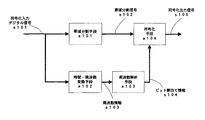
従来のサブバンド符号化システムの例としては、MPEG1オーデイオが代表例として挙げられる。従来のシステムの例であるMPEG1オーディオレイヤ1符号化方式について、図46に示す符号化システムブロック図を用いて説明する。符号化システムに入力されたサンプリング周波数fsの符号化入力デジタル信号s101を、帯域分割手段a101において、入力デジタル信号s101のナイキスト周波数(fs/2)を全帯域として、k個の帯域に分割し、k帯域分割信号s102を出力する。ここで、kは任意の整数とし、MPEG1オーディオでは、k=32の帯域幅均等分割であるが、フィルタの構成手法に応じて、k個の各分割帯域幅は、予め決められ固定値であることを条件に、均等不均等のいずれをも選択し得るものである。
【0003】
また、MPEG1オーディオレイヤにおいては、各帯域の帯域分割信号は周波数変調の一種を用いベースバンド信号にダウンサンプリングされる。これと同時に、帯域分割手段a101と時間的同期を維持した上で、符号化入力デジタル信号s101を、時間−周波数変換手段a102において、サンプリング周波数の逆数1/fsの期間を単位サンプルとするw個について時間窓掛けをおこない、時間−周波数変換して周波数情報s103を出力する。ここで、時間−周波数変換に用いられる時間窓長wは、周波数情報s103に要求される周波数分解能frに応じて、
w=(1/ fr)/(1/fs)
により求められる。
【0004】
MPEG1オーディオレイヤにおいては、時間−周波数変換手段にFFT(高速フーリエ変換)を用いているため、wの値は、所要周波数分解能frを満たす最小の2のべき乗数となっているほか、時間的連続性を考慮する形で、前後時間窓とのオーバーラップ部を設けている。周波数情報s103を基に、周波数解析手段a103において、公知の手法である聴感心理モデルに基づいた聴感マスキングによる帯域分割手段a101にて分割されるk帯域ごとに、時間−周波数変換手段a102に用いた時間窓の前後オーバーラップ部を除いた時間におけるビット割り当て数の計算をおこない、ビット割り当て情報s104を出力する。ここでの時間窓長より前後オーバーラップ部を除いた時間が、フレームの単位時間長となる。
【0005】
符号化手段a104において、各分割帯域信号s102の単位フレーム長当たりの最大振幅値より、各分割帯域ごとのスケールファクタを導出し、この各帯域ごとのスケールファクタを基に、各分割帯域信号s102の振幅を正規化したのち、ビット割り当て情報s104に基づき、各分割帯域ごとに再量子化し、これらの再量子化されたサンプルと、ビット割り当て情報、スケールファクタおよびフレーム同期用などの情報より、符号化手段a104においてビットストリームを形成し、符号化出力信号s105を出力する。
【0006】
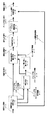
また、従来のサブバンド復号システムの例であるMPEG1オーディオレイヤ1復号方式について、図47に示す復号システムブロック図を用いて説明する。符号化システムにおいて符号化された信号が、復号入力信号s106として復号システムに入力され、フレーム解析手段a105において、フレームの検出、ビット割り当て情報の検出、スケールファクタの検出などおこない、フレーム解析情報s107を出力する。フレーム解析情報s107を基に、復号手段a06において、各分割帯域ごとに復号処理をおこない、帯域分割信号s108として出力される。帯域分割信号s108は、帯域合成手段a107において帯域合成され、復号出力信号s109として出力される。符号化−復号処理における情報の劣化をなくすため、帯域合成手段に要求される条件は、符号化システム帯域分割手段a101との間に完全再構成条件が成立することであり、この完全再構成条件を満たすフィルタ構成手段として、QMFを用いた手法などが既に公知のものである。
【0007】
【発明が解決しようとする課題】
しかしながら、従来のMPEG等で用いられているサブバンド符号化では、図46に示すように、k個の各分割帯域ごとに、スケールファクタ情報導出、ビット割り当て情報導出、再量子化処理などを実施し、各情報よりフレームを構成するため、符号化処理における処理量およびビットレートが増大するという問題があった。
【0008】
また、従来のMPEG等で用いられているサブバンド符号化では、聴感心理モデルに基づいた情報圧縮をおこなうため、時間−周波数変換をおこない、周波数領域の信号解析することが必須である。ここで、情報劣化を発生させることなく高効率圧縮を実現するためには、周波数分解能を充分に維持する必要がある。この実現のため、周波数変換をおこなう場合に、充分に長い時間サンプルに対しての窓掛けが必要であった。
【0009】
サブバンド符号化から復号処理の間に、窓掛け処理に必要なサンプル数に基づいてフレーム長が決定され、かつ、このフレーム長を基本単位として符号化処理、復号処理、バッファリング処理をおこなっている。各処理において発生するフレーム長分の処理時間と帯域分割フィルタの群遅延があるため、高音質、高圧縮率であればあるほど、処理遅延時間が増大するという問題があった。
【0010】
また、従来のMPEG等で用いられているサブバンド符号化では、周波数解析、ビット割り当てなどの処理により、符号化の処理量が多くなるという問題があった。
【0011】
さらに、従来のMPEG等で用いられているサブバンド符号化を無線伝送に用いた場合、受信システムのクロック同期捕捉および無線フレームの同期をおこなうためには、同期ワード生成および検出処理を行う必要があり、伝送路上で発生する誤りを軽減するためには、誤り訂正処理を別途追加しなければならず、各処理におけるバッファリング時間などに起因するシステム全体の処理遅延時間が増大するという問題があった。
【0012】
別途追加したこれらの誤り訂正処理は、サブバンド符号化における各情報の特徴を考慮せずに実施されるため、バーストエラーや長い時間の単位で見たビット誤り率が比較的良好な場合でも、アプリケーションレベルでは致命的エラーが発生するという問題があった。
【0013】
本発明は、上記従来の問題を解決し、サブバンド符号化および復号方式において、符号化処理量と符号化ビットレートを共に低減することを目的とする。
【0014】
【課題を解決するための手段】
上記の課題を解決するため、本発明では、サブバンド符号化方式を、符号化入力信号の帯域分割をおこない帯域分割信号を出力する帯域分割手段と、帯域分割信号の各信号出力レベルに応じてスケールファクタ情報を導出するスケールファクタ導出手段と、スケールファクタ情報を基にビット割り当て情報を計算するビット割り当て導出手段と、スケールファクタ情報を基に1フレーム前のフレームのスケールファクタ情報に対する更新情報であるスケールファクタフラグ情報とスケールファクタ更新情報を出力するスケールファクタフラグ導出手段と、帯域分割信号とスケールファクタ情報およびビット割り当て情報に基づいて再量子化をおこない再量子化出力信号を出力する再量子化手段と、再量子化出力信号とスケールファクタフラグ情報とスケールファクタ更新情報を基に符号化フレームを構成し符号化出力信号を出力するフレーム構成手段と、可聴帯域の上限周波数に基づいて再量子化信号の分割帯域数を制限する手段とを具備する構成とした。
【0015】
このように構成したことにより、周波数解析を実施せずにスケールファクタよりビット割り当てを計算し、かつスケールファクタフラグを導入して1つ前のフレームから変化したスケールファクタだけを情報としてサブバンド符号化し、聴感上の上限周波数に基づいて分割帯域数を制限して、符号化処理量と符号化ビットレートを共に低減できる。
【0016】
また、スケールファクタ情報を基にグループ化スケールファクタ情報を導出するグループ化スケールファクタ情報導出手段と、グループ化スケールファクタ情報を基にビット割り当て情報を導出し出力するビット割り当て導出手段と、グループ化スケールファクタ情報を基に前記帯域分割信号を再量子化し再量子化出力信号を出力する再量子化手段と、グループ化スケールファクタ情報を基に1フレーム前のグループ化スケールファクタ情報に対する更新情報であるグループ化スケールファクタフラグ情報とグループ化スケールファクタ更新情報を出力するスケールファクタフラグ導出手段と、グループ化スケールファクタフラグ情報と前記グループ化スケールファクタ更新情報と再量子化出力信号とより符号化出力信号を生成するフレーム構成手段とを備えた構成とした。このように構成したことにより、スケールファクタをグループ化して、符号化処理量と符号化ビットレートを共に低減できる。
【0017】
また、符号化フレーム長を(分割帯域数)/(サンプリング周波数)にする手段、または、符号化フレーム長を(分割帯域数)×2/(サンプリング周波数)にする手段を設けた構成とした。このように構成したことにより、リアルタイム出力が可能になる。
【0018】
また、ビット割り当て導出手段に、各分割帯域ごとにスケールファクタ情報とグループ化された帯域内における最小可聴曲線の最小値との比を求める手段と、最小可聴値を考慮した全帯域のエネルギー比率に基づいてビット割り当て情報を導出する手段とを設けた構成とした。このように構成したことにより、ビット割り当て処理に要する演算量を軽減できる。
【0019】
また、符号化におけるフレーム長を伝送フレーム長とする手段と、符号化時に同期ワードなどの伝送に必要な情報を付加する手段とを設け、符号化時に誤り訂正符号化処理を実施する手段を設け、符号化のフレーム構成時にインターリーブ処理を行う手段を設けた構成とした。このように構成したことにより、無線伝送に用いた場合にシステム全体の処理遅延時間を低減できる。
【0020】
また、符号化フレームを構成する各情報の誤り耐性に応じて訂正能力の異なる誤り訂正符号化処理を実施する手段を設けた構成とした。このように構成したことにより、長い時間の単位で見たビット誤り率が比較的に良好な場合のアプリケーションレベルでの致命的エラーの発生を低減できる。
【0021】
【発明の実施の形態】
本発明の請求項1記載の発明は、符号化入力信号の帯域分割をおこない帯域分割信号を出力する帯域分割手段と、前記帯域分割信号の各信号出力レベルに応じてスケールファクタを導出するスケールファクタ導出手段と、前記スケールファクタ情報を基にビット割り当て情報を計算するビット割り当て導出手段と、前記スケールファクタ導出手段からのスケールファクタ情報を基に1フレーム前のフレームのスケールファクタ情報に対する更新情報であるスケールファクタフラグ情報とスケールファクタ更新情報を出力するスケールファクタフラグ導出手段と、前記帯域分割信号と前記スケールファクタ情報および前記ビット割り当て情報に基づいて再量子化をおこない再量子化出力信号を出力する再量子化手段と、前記再量子化出力信号と前記スケールファクタフラグ情報と前記スケールファクタ更新情報を基に符号化フレームを構成し符号化出力信号を出力するフレーム構成手段と、可聴帯域の上限周波数に基づいて前記再量子化信号の分割帯域数を制限する手段とを具備するサブバンド符号化方式であり、スケールファクタよりビット割り当てを計算し、スケールファクタフラグを導入して1つ前のフレームから変化したスケールファクタだけを情報としてサブバンド符号化し、聴感上の上限周波数に基づいて分割帯域数を制限して、符号化処理量と符号化ビットレートを共に低減するという作用を有する。
【0022】
本発明の請求項2記載の発明は、サブバンド符号化信号を復号入力信号としてフレーム同期を取った上で再量子化信号とスケールファクタ更新情報とスケールファクタフラグ情報を検出し出力するフレーム解析手段と、前記スケールファクタ更新情報およびスケールファクタフラグ情報を基に全分割帯域のスケールファクタ情報を出力するスケールファクタ検出手段と、前記スケールファクタ情報を基にビット割り当て情報を導出するビット割り当て導出手段と、前記スケールファクタ情報および前記ビット割り当て情報に基づいて前記再量子化信号より帯域分割信号を導出する帯域分割信号導出手段と、前記帯域分割信号より帯域合成をおこなう帯域合成手段とを具備するサブバンド復号方式であり、スケールファクタ更新情報とスケールファクタフラグ情報からスケールファクタ情報を求めて、帯域合成をおこなうという作用を有する。
【0023】
本発明の請求項3記載の発明は、請求項1記載のサブバンド符号化方式において、前記スケールファクタ情報を基にグループ化スケールファクタ情報を導出するグループ化スケールファクタ情報導出手段と、前記グループ化スケールファクタ情報を基にビット割り当て情報を導出し出力するビット割り当て導出手段と、前記グループ化スケールファクタ情報を基に前記帯域分割信号を再量子化し再量子化出力信号を出力する再量子化手段と、前記グループ化スケールファクタ情報を基に1フレーム前のグループ化スケールファクタ情報に対する更新情報であるグループ化スケールファクタフラグ情報とグループ化スケールファクタ更新情報を出力するスケールファクタフラグ導出手段と、前記グループ化スケールファクタフラグ情報と前記グループ化スケールファクタ更新情報と前記再量子化出力信号とより符号化出力信号を生成するフレーム構成手段とを備えたものであり、スケールファクタをグループ化して、符号化処理量と符号化ビットレートを共に低減するという作用を有する。
【0024】
本発明の請求項4記載の発明は、請求項2記載のサブバンド復号方式において、サブバンド符号化信号を復号入力信号としてフレーム同期を取った上で再量子化信号とグループ化スケールファクタ更新情報およびグループ化スケールファクタフラグ情報などの符号化フレーム構成情報を検出し出力するフレーム解析手段と、前記グループ化スケールファクタ更新情報およびグループ化スケールファクタフラグ更新情報よりグループ化スケールファクタ情報を導出するスケールファクタ検出手段と、前記グループ化スケールファクタ情報を基にビット割り当て情報を導出するビット割り当て導出手段と、前記グループ化スケールファクタ情報と前記ビット割り当て情報と前記再量子化信号とを基に帯域分割信号を導出する帯域分割信号導出手段とを備えたものであり、グループ化スケールファクタ更新情報およびグループ化スケールファクタフラグ情報からグループ化スケールファクタ情報を求めて、帯域合成をおこなうという作用を有する。
【0025】
本発明の請求項5記載の発明は、請求項1、3記載のサブバンド符号化方式において、((符号化入力信号サンプリング周波数/2)/(帯域分割数)×(上限周波数分割帯域番号))≧(アプリケーション上の上限周波数)を満足する最も小さい整数に基づいて上限周波数分割帯域番号を決定して符号化処理上限周波数を設定する手段を設けたものであり、アプリケーションの要求を満足する最小の上限周波数を設定するという作用を有する。
【0026】
本発明の請求項6記載の発明は、請求項1、3、5記載のサブバンド符号化方式において、(サンプリング周波数)/2の帯域内を32の分割帯域に分けて処理する場合に、前記スケールファクタ情報およびスケールファクタフラグ情報を6〜20帯域群にグループ化して処理する手段を設けたものであり、分割帯域数を可能な限りグループ化して、符号化ビットレートおよび符号化処理量および符号化ビットレートを低減するという作用を有する。
【0027】
本発明の請求項7記載の発明は、請求項1、3、5記載のサブバンド符号化方式において、符号化フレーム長を(分割帯域数)/(サンプリング周波数)にする手段を設けたものであり、符号化における処理遅延時間を低減してリアルタイム出力を可能にするという作用を有する。
【0028】
本発明の請求項8記載の発明は、請求項1、3、5記載のサブバンド符号化方式において、符号化フレーム長を(分割帯域数)×2/(サンプリング周波数)にする手段を設けたものであり、符号化における処理遅延時間を低減してリアルタイム出力を可能にするという作用を有する。
【0029】
本発明の請求項9記載の発明は、請求項3、5記載のサブバンド符号化方式において、前記ビット割り当て導出手段に、各分割帯域ごとに前記スケールファクタ情報とグループ化された帯域内における最小可聴曲線の最小値との比を求める手段と、最小可聴値を考慮した全帯域のエネルギー比率に基づいてビット割り当て情報を導出する手段とを設けたものであり、ビット割り当て処理に要する演算量を軽減するという作用を有する。
【0030】
本発明の請求項10記載の発明は、請求項3、5記載のサブバンド符号化方式において、前記ビット割り当て導出手段に、各分割帯域ごとに前記スケールファクタ情報とグループ化された帯域内における最小可聴曲線の平均値との比を求める手段と、最小可聴値を考慮した全帯域のエネルギー比率に基づいてビット割り当て情報を導出する手段とを設けたものであり、ビット割り当て処理に要する演算量を軽減するという作用を有する。
【0031】
本発明の請求項11記載の発明は、請求項1、3、5記載のサブバンド符号化方式において、前記ビット割り当て導出手段に、ビット割り当て情報の整数化処理において小数点以下切り捨てにより発生する割り当て可能な余りビットを、エネルギー比率における小数点以下の値の大きい帯域順に割り当てていく手段を設けたものであり、符号化ビットを有効利用するという作用を有する。
【0032】
本発明の請求項12記載の発明は、請求項1、3、5記載のサブバンド符号化方式において、前記ビット割り当て情報導出手段に、周波数領域における重み付け係数をかけた状態でビット割り当て情報を導出する手段を設けたものであり、符号化処理による音質を向上するという作用を有する。
【0033】
本発明の請求項13記載の発明は、請求項1、3、5記載のサブバンド符号化方式において、前記ビット割り当て情報導出手段に、各分割帯域のスケールファクタ情報ごとの重み付け係数をかけた状態でビット割り当て情報を導出する手段を設けたものであり、符号化処理による音質を向上するという作用を有する。
【0034】
本発明の請求項14記載の発明は、請求項1、3、5記載のサブバンド符号化方式において、符号化におけるフレーム長を伝送フレーム長とする手段と、符号化時に同期ワードなどの伝送に必要な情報を付加する手段とを設けたものであり、無線伝送に用いた場合の伝送路符号化および復号処理におけるバッファリング時間と処理量を短縮し、符号化ビットレートを低減するという作用を有する。
【0035】
本発明の請求項15記載の発明は、請求項1、3、5記載のサブバンド符号化方式において、フレーム内の全ての情報が同期捕捉用同期ワードであるフレームを一定の時間間隔ごとに伝送する手段を設けたものであり、無線伝送に用いた場合の伝送誤りによるスケールファクタ情報の劣化からの復帰時間を短縮するという作用を有する。
【0036】
本発明の請求項16記載の発明は、請求項1、3、5記載のサブバンド符号化方式において、グループ化された全てのスケールファクタ情報で構成されたフレームを一定の時間間隔ごとに伝送する手段を設けたものであり、無線伝送に用いた場合の伝送誤りによるスケールファクタ情報の劣化からの復帰時間を短縮するという作用を有する。
【0037】
本発明の請求項17記載の発明は、請求項1、3、5記載のサブバンド符号化方式において、グループ化された全てのスケールファクタ情報と複数の同期捕捉用同期ワードで構成されたフレームを一定の時間間隔ごとに伝送する手段を設けたものであり、無線伝送に用いた場合の伝送誤りによるスケールファクタ情報の劣化からの復帰時間を短縮するという作用を有する。
【0038】
本発明の請求項18記載の発明は、請求項2、4記載のサブバンド復号方式において、一定の時間間隔で送られてくるグループ化されたスケールファクタ情報または同期捕捉用同期ワードもしくはその両方で構成されるフレームをミュート処理する手段と、データ補間処理を復号処理部のデジタル信号に対して実施する手段とを設けたものであり、符号化および復号により発生する1フレーム分のデータブランクをユーザー側で検知されないように補間するという作用を有する。
【0039】
本発明の請求項19記載の発明は、請求項2、4記載のサブバンド復号方式において、一定の時間間隔で送られてくるグループ化されたスケールファクタ情報または同期捕捉用同期ワードもしくはその両方で構成されるフレームをミュート処理する手段と、データ補間処理を復号処理部のアナログ信号に対して実施する手段とを設けたものであり、符号化および復号により発生する1フレーム分のデータブランクをユーザー側で検知されないように補間するという作用を有する。
【0040】
本発明の請求項20記載の発明は、請求項1、3、5記載のサブバンド符号化方式において、符号化時に誤り訂正符号化処理を実施する手段を設けたものであり、無線伝送に用いた場合の伝送誤りを低減するという作用を有する。
【0041】
本発明の請求項21記載の発明は、請求項20記載のサブバンド符号化方式において、符号化フレームを構成する各情報の誤り耐性に応じて訂正能力の異なる誤り訂正符号化処理を実施する手段を設けたものであり、無線伝送に用いた場合の伝送誤りを低減するという作用を有する。
【0042】
本発明の請求項22記載の発明は、請求項20記載のサブバンド符号化方式において、BCH符号を用いる手段を設けたものであり、無線伝送に用いた場合の伝送誤りを低減するという作用を有する。
【0043】
本発明の請求項23記載の発明は、請求項20記載のサブバンド符号化方式において、畳み込み符号を用いる手段を設けたものであり、無線伝送に用いた場合の伝送誤りを低減するという作用を有する。
【0044】
本発明の請求項24記載の発明は、請求項20記載のサブバンド符号化方式において、符号化フレームを構成する各情報の誤り耐性に応じて異なる誤り訂正符号を用いる誤り訂正符号化処理手段を設けたものであり、無線伝送に用いた場合の伝送誤りを低減するという作用を有する。
【0045】
本発明の請求項25記載の発明は、請求項24記載のサブバンド符号化方式において、BCH符号と畳み込み符号で実現する手段を設けたものであり、無線伝送に用いた場合の伝送誤りを低減するという作用を有する。
【0046】
本発明の請求項26記載の発明は、請求項20記載のサブバンド符号化方式において、符号化フレームにおける情報の重み付けに応じてフレーム内に誤り訂正符号化しないビットを設けたものであり、符号化ビットレートを低減するという作用を有する。
【0047】
本発明の請求項27記載の発明は、請求項20〜26記載のサブバンド符号化方式において、前記符号化フレームごとに情報量の変化するスケールファクタ更新情報の変化を考慮せず固定的に誤り訂正符号化処理をおこなう手段を設けたものであり、符号化ビットレートを低減するという作用を有する。
【0048】
本発明の請求項28記載の発明は、請求項27記載のサブバンド符号化方式において、再量子化出力信号を符号誤りによる影響を考慮した形で並び替える手段を設けたものであり、アプリケーションレベルでの符号誤りによる劣化を低減するという作用を有する。
【0049】
本発明の請求項29記載の発明は、請求項2、4記載のサブバンド復号方式において、誤り訂正符号化復号手段で検出される1フレーム当たりの誤りビット数に応じて、該当フレームのミュート処理を行う手段と、データ補間処理を復号処理部のデジタル信号に対して実施する手段とを設けたものであり、無線伝送で発生する符号誤りをユーザー側で検知されないように補間するという作用を有する。
【0050】
本発明の請求項30記載の発明は、請求項2、4記載のサブバンド復号方式において、誤り訂正符号化復号手段で検出される1フレーム当たりの誤りビット数に応じて、該当フレームのミュート処理を行う手段と、データ補間処理を復号処理部のアナログ信号に対して実施する手段とを設けたものであり、無線伝送で発生する符号誤りをユーザー側で検知されないように補間するという作用を有する。
【0051】
本発明の請求項31記載の発明は、請求項1、3、5記載のサブバンド符号化方式において、符号化のフレーム構成時にインターリーブ処理を行う手段を設けたものであり、無線伝送に用いた場合のバースト的な伝送誤りを低減するという作用を有する。
【0052】
本発明の請求項32記載の発明は、請求項2、4記載のサブバンド復号方式において、復号処理の無線伝送フレーム解析時にデインターリーブ処理を実施する手段を設けたものであり、無線伝送に用いた場合のバースト的な伝送誤りを低減する
という作用を有する。
【0053】
以下、本発明の実施の形態について、図1〜図45を参照しながら詳細に説明する。
【0054】
(第1の実施の形態)
本発明の第1の実施の形態は、符号化入力信号を帯域分割し、分割帯域帯域ごとのスケールファクタ情報を基にビット割り当て情報を計算し、1フレーム前のスケールファクタ情報に対する更新情報であるスケールファクタフラグ情報とスケールファクタ更新情報を求め、帯域分割信号とスケールファクタ情報およびビット割り当て情報と可聴帯域の上限周波数に基づいて、分割帯域数を制限して再量子化をおこない、再量子化出力信号とスケールファクタフラグ情報とスケールファクタ更新情報を基に符号化フレームを構成するサブバンド符号化方式である。
【0055】
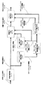
図1は、本発明の第1の実施の形態におけるサブバンド符号化方式の機能ブロック図である。図1において、帯域分割手段a01は、符号化入力信号を、複数個の帯域に分割する手段である。スケールファクタ導出手段a02は、分割帯域ごとに最大振幅レベルを検出して正規化の倍率係数を導出する手段である。ビット割り当て導出手段a04は、スケールファクタ情報より帯域ごとのビット割り当てを導出する手段である。スケールファクタフラグ導出手段a05は、スケールファクタの変化を示すスケールファクタフラグ情報と変化したスケールファクタ情報のみを出力する手段である。再量子化手段06は、帯域分割信号を各分割帯域ごとに再量子化する手段である。フレーム構成手段a07は、スケールファクタ更新情報とスケールファクタフラグ情報および再量子化出力信号を用いて符号化フレームを構成する手段である。
【0056】
図2は、本発明の第1の実施の形態におけるサブバンド符号化および復号方式の周波数帯域分割と処理上限周波数の関係を示す図である。図3は、サブバンド符号化および復号方式のフレーム構成を示す図である。図3において、headerは、符号化フレーム同期検出用信号などの付加情報である。スケールファクタフラグ情報s05は、スケールファクタの変化を示す情報である。スケールファクタ更新情報s06は、1フレーム前に対して変化したスケールファクタ情報である。再量子化出力信号s08は、帯域分割信号を各分割帯域ごとに再量子化した信号である。
【0057】
上記のように構成された本発明の第1の実施の形態におけるサブバンド符号化方式について、図1に示す符号化方式ブロック図、図2に示す周波数帯域分割と処理上限周波数の関係図および図3に示す符号化方式フレーム構成例で説明する。まず、帯域分割手段a01において、符号化システムに入力されたサンプリング周波数fsの符号化入力信号s00を、図2に示すように、符号化入力信号s00のナイキスト周波数(fs/2)を全帯域とするk個の帯域に分割する。ここで、kは任意の整数とし、MPEG1オーディオでは、k=32の帯域幅均等分割であるが、フィルタの構成手法に応じて、k個の各分割帯域幅は、予め決められた値であることを条件に、均等不均等のいずれをも選択し得るものとする。帯域分割手段a01における分割帯域数はk個であるが、帯域分割手段a01からは、n帯域の帯域分割信号s01が出力される。ここで、nは1から(k−1)の任意の整数であるが、図2に示すnの値は、アプリケーションに応じた上限周波数をもとに決定される。また、各帯域分割信号s01は、周波数変調の一種を用い、ベースバンド信号にダウンサンプリングされたものである。
【0058】
スケールファクタ導出手段a02において、帯域分割手段a01と時間的同期を維持した上で、n個の分割帯域ごとに、フレーム時間長のサンプルに対応する帯域分割信号s01の最大振幅レベルを検出したのち、最大振幅レベルを任意の値に正規化するための倍率係数であるスケールファクタを導出し、スケールファクタ情報s02として出力する。このとき、(n+1)番目からk番目までの帯域のスケールファクタ値は、最大倍率、つまり信号振幅最小値を示す倍率とする。また、以降の処理においても、入力信号のフレーム時間長のサンプルに対応する値を単位入力および出力として処理がなされる。正規化レベルに関しては、符号化ブロックにおいて最大入力音圧相当の値にするのが一般的である。
【0059】
ビット割り当て導出手段a04において、n帯域分のスケールファクタ情報よりn帯域ごとのビット割り当てを導出し、ビット割り当て情報s04として出力する。このとき、(n+1)番目からk番目までの帯域の割り当て値は0、つまりビット割り当てなしとする。
【0060】
スケールファクタフラグ導出手段a05において、スケールファクタ情報s02が1フレーム前のスケールファクタに対して変化しているかどうかを判断し、n個の分割帯域につき1ビットで、スケールファクタの変化を示すスケールファクタフラグ情報s05を出力する。また、1フレーム前に対して変化したスケールファクタ情報のみを、スケールファクタ更新情報s06として出力する。同時に、再量子化手段a06において、ビット割り当て情報s04およびスケールファクタ情報s02に基づいて、帯域分割信号s01を各分割帯域ごとに再量子化し、再量子化出力信号s08を出力する。
【0061】
フレーム構成手段a07において、符号化フレーム同期検出用信号などの情報を付加したのち、スケールファクタ更新情報s06とスケールファクタフラグ情報s05および再量子化出力信号s08を用いて、図3に示す符号化フレームを構成し、符号化出力信号s09として出力する。なお、図3におけるs05、s06およびs08は、図1における各信号に対応するものである。図3において、付加情報であるheaderは、フレームの時間的先頭に配置された形を取っているが、符号化処理と復号処理の間で一定の規則性を持った形で統一されていることを条件として、フレームにおける付加情報の位置は任意とする。また、その他の情報の順番についても、符号化処理と復号処理の間で統一されていることを条件に可変とする。
【0062】
具体的な符号化の構成例を、図2に示す周波数帯域分割と処理上限周波数の関係図で説明する。アプリケーション上の上限周波数yを20kHzとし、図2における符号入力信号および復号出力信号のサンプリング周波数fsを48kHzとし、帯域分割数kを32とする。この場合、
((符号化入力信号サンプリング周波数/2)/(帯域分割数)×(上限周波数分割帯域番号))≧(アプリケーション上の上限周波数)
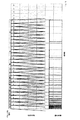
を満足する最も小さい整数である上限周波数分割帯域番号nは27となる。これをもとに、帯域分割処理および帯域合成処理を行う。符号化ならびに復号処理におけるスケールファクタ情報、スケールファクタフラグ情報およびビット割り当て情報の導出に関しては、低域の27の分割帯域についてのみ行う。これにより、理論的な符号化処理上限周波数xは、20.25kHzとなる。また、高域の残りの分割帯域に関しては、符号化フレームを構成するにあたっても全く考慮せず、復号出力信号においても0値を取る。以下に、具体的な数値例を表にして示す。
番号 y(kHz) fs(kHz) k n x(kHz)
1 20 48 32 27 20.25
2 20 44.1 32 30 20.671875
3 20 96 64 54 20.25
4 15 48 32 20 15
5 15 44.1 32 11 15.1597375
6 15 44.1 64 40 15
7 15 32 32 30 15
8 10 48 32 14 10.5
9 10 44.1 32 28 11.025
10 10 96 64 28 10.5
11 10 32 32 20 10
12 7 48 32 10 7.5
13 7 44.1 32 6 8.26875
14 7 96 64 20 7.5
15 7 32 32 14 7
【0063】
上記のように、本発明の第1の実施の形態では、サブバンド符号化方式を、符号化入力信号を帯域分割し、分割帯域帯域ごとのスケールファクタ情報を基にビット割り当て情報を計算し、1フレーム前のスケールファクタ情報に対する更新情報であるスケールファクタフラグ情報とスケールファクタ更新情報を求め、帯域分割信号とスケールファクタ情報およびビット割り当て情報と可聴帯域の上限周波数に基づいて、分割帯域数を制限して再量子化をおこない、再量子化出力信号とスケールファクタフラグ情報とスケールファクタ更新情報を基に符号化フレームを構成するようにしたので、スケールファクタフラグを導入して1つ前のフレームから変化したスケールファクタだけを情報としてサブバンド符号化し、聴感上の上限周波数に基づいて分割帯域数を制限して、符号化処理量と符号化ビットレートを共に低減できる。
【0064】
(第2の実施の形態)
本発明の第2の実施の形態は、サブバンド符号化信号を入力して再量子化信号とスケールファクタ更新情報とスケールファクタフラグ情報を検出し、スケールファクタ更新情報およびスケールファクタフラグ情報を基に全分割帯域のスケールファクタ情報を求め、スケールファクタ情報を基にビット割り当て情報を導出し、スケールファクタ情報およびビット割り当て情報に基づいて再量子化信号より帯域分割信号を導出し、帯域分割信号より帯域合成をおこなうサブバンド復号方式である。
【0065】
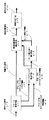
図4は、本発明の第2の実施の形態におけるサブバンド復号方式の機能ブロック図である。図4において、フレーム解析手段a11は、スケールファクタフラグ情報、スケールファクタ更新情報および再量子化信号を検出する手段である。スケールファクタ検出手段a12は、分割帯域のスケールファクタ情報を導出する手段である。ビット割当て導出手段a13は、スケールファクタ情報より、帯域ごとのビット割り当てを導出する手段である。帯域分割信号導出手段a14は、再量子化信号を各分割帯域ごとに検出し、帯域分割信号を導出する手段である。帯域合成手段a15は、帯域分割信号を帯域合成して復号出力信号を出力する手段である。
【0066】
上記のように構成された本発明の第2の実施の形態におけるサブバンド復号方式について、図4に示す復号方式ブロック図、図2に示す周波数帯域分割例および図3に示す符号化方式フレーム構成例で説明する。図4において、復号部の入力信号である復号入力信号s10は、図3に示す符号化方式フレーム構成を持つ信号であり、フレーム解析手段a11において図3の各情報を解析する。具体的には、まず、図3のheaderに基づいて符号化フレームの同期を取り、n個のスケールファクタフラグ情報s13、スケールファクタ更新情報s12および再量子化信号s11を検出し、それぞれ出力する。
【0067】
フレーム解析手段a11からの各出力は、フレーム単位で出力され、以降の処理は、フレーム単位で実施される。スケールファクタ更新情報s12、スケールファクタフラグ情報s13および1フレーム前のスケールファクタ情報をもとに、スケールファクタ検出手段a12において、k個の分割帯域のスケールファクタ情報を導出し、スケールファクタ情報s20として出力する。このとき、(n+1)番目からk番目までの帯域のスケールファクタ値は、最大倍率、つまり信号振幅最小値を示す倍率に強制的に設定する。また、以降の処理においても、入力信号のフレーム時間長のサンプルに対応する値を単位入力および出力として処理がなされる。
【0068】
ビット割り当て導出手段a13において、n帯域分のスケールファクタ情報より、n帯域ごとのビット割り当てを導出し、ビット割り当て情報s17として出力する。このとき、(n+1)番目からk番目までの帯域の割り当て値は0、つまりビット割り当てなしとする。
【0069】
帯域分割信号導出手段a14において、ビット割り当て情報s17に基づいて、再量子化信号s11を各分割帯域ごとに検出し、スケールファクタ情報s20をもとに、帯域分割信号s18を導出して出力する。
【0070】
帯域合成手段a15において、帯域分割信号s18を帯域合成し、復号出力信号s19を出力する。また、帯域合成処理は、図2に示すように、符号化処理同様、ナイキスト周波数(fs/2)を全帯域とするk個の帯域で構成されている。復号出力信号s19は、サンプリング周波数fsの逆数の時間間隔で出力され、振幅レベルは、量子化ビット数に応じて2値表現されるものである。
【0071】
上記のように、本発明の第2の実施の形態では、サブバンド復号方式を、サブバンド符号化信号を入力して再量子化信号とスケールファクタ更新情報とスケールファクタフラグ情報を検出し、スケールファクタ更新情報およびスケールファクタフラグ情報を基に全分割帯域のスケールファクタ情報を求め、スケールファクタ情報を基にビット割り当て情報を導出し、スケールファクタ情報およびビット割り当て情報に基づいて再量子化信号より帯域分割信号を導出し、帯域分割信号より帯域合成をおこなう構成としたので、復号処理する分割帯域を制限して、サブバンド符号化復号処理における符号化処理量を低減できる。
【0072】
(第3の実施の形態)
本発明の第3の実施の形態は、スケールファクタ情報から導出したグループ化スケールファクタ情報を基に、ビット割り当て情報を導出し、帯域分割信号を再量子化し、1フレーム前のグループ化スケールファクタ情報に対する更新情報であるグループ化スケールファクタフラグ情報とグループ化スケールファクタ更新情報を求め、再量子化出力信号とより符号化出力信号を生成するサブバンド符号化方式である。
【0073】
図5は、本発明の第3の実施の形態におけるサブバンド符号化方式の機能ブロック図である。図5において、グループ化スケールファクタ情報導出手段a03は、スケールファクタ情報を複数帯域ごとにグループ化する手段である。その他の基本的な構成は第1の実施の形態と同じである。
【0074】
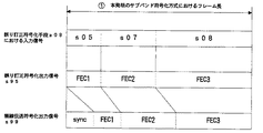
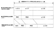
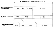
図6は、本発明の第3の実施の形態におけるサブバンド符号化および復号方式の分割帯域数とスケールファクタ情報の帯域数の関係を示す図である。図7は、サブバンド符号化および復号方式のフレーム構成を示す図である。図7において、グループ化スケールファクタ更新情報s07は、1フレーム前に対して変化したスケールファクタ情報である。
【0075】
図9は、本発明の第3の実施の形態におけるサブバンド符号化および復号方式の周波数帯域分割のグループ化を説明する図である。図10は、サブバンド符号化および復号方式の周波数帯域分割のグループ化を説明する図である。図11は、サブバンド符号化および復号方式の周波数帯域分割のグループ化を説明する図である。図12は、サブバンド符号化方式の符号化処理のタイミングチャートである。図14は、サブバンド符号化方式の符号化処理のタイミングチャートである。図16は、サブバンド符号化および復号方式の周波数特性図である。図17は、サブバンド符号化および復号方式の周波数特性図である。
【0076】
上記のように構成された本発明の第3の実施の形態におけるサブバンド符号化方式について、図5に示す符号化方式ブロック図、図6に示す分割帯域数とスケールファクタ情報の帯域数の説明図および図7に示す符号化方式フレーム構成例で説明する。
【0077】
帯域分割手段a01において、符号化システムに入力されたサンプリング周波数fsの符号化入力信号s00を、図2に示すように、符号化入力信号s00のナイキスト周波数(fs/2)を全帯域とするk個の帯域に分割する。ここで、kは任意の整数とし、MPEG1オーディオではk=32の帯域幅均等分割であるが、フィルタの構成手法に応じて、k個の各分割帯域幅は、予め決められた値であることを条件に、均等不均等のいずれをも選択し得るものとする。帯域分割手段における分割帯域数はk個であるが、帯域分割手段からは、n帯域の帯域分割信号s01が出力される。ここで、nは1から(k−1)の任意の整数であるが、nの値は、図2の例における20kHz相当の分割帯域といったように、一般的な聴感上の上限周波数をもとに決定する。また、各帯域分割信号s01は、周波数変調の一種を用い、ベースバンド信号にダウンサンプリングされたものである。
【0078】
スケールファクタ導出手段a02において、帯域分割手段a01と時間的同期を維持した上で、n個の分割帯域ごとに、フレーム時間長のサンプルに対応する帯域分割信号s01の最大振幅レベルを検出したのち、最大振幅レベルを任意の値に正規化するための倍率係数であるスケールファクタを導出し、スケールファクタ情報s02として出力する。ここで、(n+1)番目からk番目までの帯域のスケールファクタ値は、最大倍率、つまり信号振幅最小値を示す倍率とする。また、以降の処理においても、入力信号のフレーム時間長のサンプルに対応する値を単位入力および出力として処理がなされる。正規化レベルに関しては、符号化ブロックにおいて最大入力音圧相当の値にするのが一般的である。
【0079】
また、グループ化スケールファクタ情報導出手段a03において、スケールファクタ情報s02を、n個の分割帯域からm個の帯域にグループ化し、グループ化スケールファクタ情報s03として出力する。図6は、分割帯域のグループ化を説明する図であり、k=32、n=27の場合の例である。また、mはnより小さい任意の自然数とし、図6の例において、mは1〜26までの値を取りうるが、音質面を考えた場合、グループ化は、公知の特性である聴感上の臨界帯域幅にのっとった形で実施されることが最も好ましい。
【0080】
ビット割り当て導出手段a04において、n帯域分のグループ化スケールファクタ情報s03より、n帯域ごとのビット割り当てを導出し、ビット割り当て情報s04として出力する。ここで、(n+1)番目からk番目までの帯域の割り当て値は0、つまりビット割り当てなしとする。
【0081】
スケールファクタフラグ導出手段a05において、グループ化スケールファクタ情報s03が、1フレーム前のグループ化スケールファクタ情報に対して変化しているかどうかを判断し、m個の帯域につき1ビットで、スケールファクタの変化を示すスケールファクタフラグ情報s05を出力する。また、1フレーム前に対して変化したスケールファクタ情報のみを、グループ化スケールファクタ更新情報s07として出力する。同時に、再量子化手段a06において、ビット割り当て情報s04およびグループ化スケールファクタ情報s03に基づいて、帯域分割信号s01を各分割帯域ごとに再量子化し、再量子化出力信号s06を出力する。
【0082】
フレーム構成手段a07において、符号化フレーム同期検出用信号などの情報を付加したのち、グループ化スケールファクタ更新情報s07、スケールファクタフラグ情報s05および再量子化出力信号s08を用いて、図7に示す符号化フレームを構成し、符号化出力信号s09として出力する。なお、図7におけるs05、s07およびs08は、図5における各信号に対応するものである。
【0083】
分割帯域のグループ化の具体例1を、図9に示す周波数帯域分割のグループ化説明図で説明する。図9に示す例においては、fs=48kHzであり、(fs/2)=24kHzの帯域を32の分割帯域に分け、上限分割帯域設定は、第27番目の分割帯域とする。また、図9下部に、公知の特性である聴覚上の臨界帯域の例を示す。
【0084】
図9に示すように、符号化処理をおこなう27の分割帯域に対して、第11番目と第12番目の分割帯域、第13番目と第14番目の分割帯域、第15番目と第16番目の分割帯域、第17番目から第19番目の分割帯域、第20番目から第22番目の分割帯域、第23番目から第27番目の分割帯域を、それぞれグループ化する。ここで、第1番目から第10番目の分割帯域は、グループ化を実施しない。これにより、16の分割帯域グループが存在することになるが、各グループごとに16のグループ化スケールファクタ情報とグループ化スケールファクタフラグ情報を導出する。グループ化スケールファクタ情報の導出に関しては、グループを構成する各分割帯域において最もスケールファクタ値の小さいものを値として選び、グループ内の分割帯域は、全てこの値をスケールファクタ値とする。
【0085】
分割帯域のグループ化の具体例2を、図10に示す周波数帯域分割のグループ化説明図で説明する。図10に示す例においては、fs=48kHzであり、(fs/2)=24kHzの帯域を323の分割帯域に分け、上限分割帯域設定は、第27番目の分割帯域とする。また、図10下部に、公知の特性である聴覚上の臨界帯域の例を示す。
【0086】
図10に示すように、符号化処理をおこなう27の分割帯域に対して、第11番目と第12番目の分割帯域、第13番目から第15番目の分割帯域、16第番目から第20番目の分割帯域、第21番目から第27番目の分割帯域をそれぞれグループ化する。ここで、第1番目から第10番目の分割帯域はグループ化を実施しない。これにより、14の分割帯域グループが存在することになるが、各グループごとに14のグループ化スケールファクタ情報とグループ化スケールファクタフラグ情報を導出する。
【0087】
分割帯域のグループ化の具体例3を、図11に示す周波数帯域分割のグループ化説明図で説明する。図11に示す例においては、fs=48kHzであり、(fs/2)=24kHzの帯域を32の分割帯域に分け、上限分割帯域設定は、第27番目の分割帯域とする。また、図11下部に、公知の特性である聴覚上の臨界帯域の例を示す。
【0088】
図11に示すように、符号化処理をおこなう27の分割帯域に対して、第2番目と第3番目の分割帯域、第4番目と第5番目の分割帯域、第6番目と第7番目の分割帯域、第8番目と第9番目の分割帯域、第10番目から第12番目の分割帯域、第13番目から第15番目の分割帯域、第16番目から第20番目の分割帯域、第21番目から第27番目の分割帯域をそれぞれグループ化する。ここで、第1番目の分割帯域はグループ化を実施しない。これにより、9の分割帯域グループが存在することになるが、各グループごとに、9のグループ化スケールファクタ情報とグループ化スケールファクタフラグ情報を導出する。
【0089】
符号化処理のタイミングの例1を、図12に示す符号化処理タイミングチャート、図5に示す符号化方式ブロック図、図6に示す分割帯域数とスケールファクタ情報の帯域数の説明図で説明する。なお、図6は、k=32,n=27の例であり、分割帯域グループ数mは、2から(n−1)の任意の整数とする。また、図12におけるs00,s03,s08,s09は、図5における各信号に対応し、fs,kは、図6のものと同一値である。
【0090】
図5の帯域分割手段a01に入力される符号化入力信号s00は、1/(サンプリング周波数fs)の時間間隔で、量子化ビット数に対応した情報が入力される。これらを図12に示すように、i(1),i(2),…と表現する。
【0091】
帯域分割手段a01においては、図6に示すように、(fs/2)の帯域をk個の帯域に分割する。帯域分割処理において、第1番目の帯域に分割するため必要となる入力符号化信号s00はk個であり、これが符号化処理における最小入力単位となる。このため、図12に示すように、i(1)からi(k)までの符号化入力信号s00に対して、図5のa01からa07までの符号化処理を実施し、図12に示すような、(分割帯域数k)/(サンプリング周波数fs)の時間長のフレームを構成する。また、実時間処理を実現するため、符号化処理は、図12に示すように、2×(分割帯域数k)/(サンプリング周波数fs)以下の時間で処理をおこなう。
【0092】
符号化処理のタイミングの例2を、図14に示す符号化処理タイミングチャート、図5に示す符号化方式ブロック図、図6に示す分割帯域数とスケールファクタ情報の帯域数の説明図で説明する。なお、図6は、k=32,n=27の例であり、分割帯域グループ数mは、2から(n−1)の任意の整数とする。また、図14におけるs00,s03,s08,s09は、図5における各信号に対応し、fs,kは、図6のものと同一値である。
【0093】
図5の帯域分割手段a01に入力される符号化入力信号s00は、1/(サンプリング周波数fs)の時間間隔で、量子化ビット数に対応した情報が入力される。これらを、図14に示すように、i(1),i(2),…と表現する。また、帯域分割手段a01においては、図6に示すように、(fs/2)の帯域をk個の帯域に分割する。帯域分割処理において、第1番目の帯域に分割するため必要となる入力符号化信号s00はk個であり、これが符号化処理における最小入力単位となる。ここで、図14に示すように、i(1)からi(2k)までの符号化入力信号s00に対して、図5のa01からa07までの符号化処理を実施し、図14に示すような、2×(分割帯域数k)/(サンプリング周波数fs)の時間長のフレームを構成する。また、実時間処理を実現するため、符号化処理は、図14に示すように、4×(分割帯域数k)/(サンプリング周波数fs)以下の時間で処理をおこなう。
【0094】
正規化処理の例1を、図16に示す周波数特性図、図5に示す符号化方式ブロック図で説明する。この例1では、分割帯域数k=32、グループ化帯域数m=14、符号化入力サンプリング周波数fs=48kHz、符号化処理上限周波数分割帯域n=27、フレーム長=(32/48000)secとする。図16に示す入力信号は、図5の符号化入力信号s00の1フレーム相当の時間における周波数特性を示すものである。
【0095】
図5のグループ化スケールファクタ情報導出手段a03において、入力信号周波数特性より図16のf1、f2、…、f14に示すように、14のグループ化分割帯域ごとにスケールファクタ情報を導出する。f1、f2、…、f14は、それぞれ各グループにおける入力信号の最大値と正規化レベルの比を表す値である。
【0096】
図5のビット割り当て導出手段a04において、図16に示すように、27の各分割帯域ごとの、グループ化スケールファクタ情報と公知の特性である聴感上の最小可聴値の分割帯域における最小値の比b1、b2、…、b27を導出する。図16において、b17からb27までの値が存在しないのは、第17番目の分割帯域において、最小可聴値より入力信号が小さい値になっているためである。この場合、第17から27番目の分割帯域のビット割り当ては0となる。入力信号レベルのb1、b2、…、b27より、各分割帯域ごとのエネルギー比率を以下の式より導出する。
【数1】

ただし、iは1から27までの整数とする。さらに、各分割帯域ごとにエネルギー比率と1フレームの割り当て可能ビット数の積を求め、この値を整数化することで、各分割帯域ごとのビット割り当て情報s04を導出する。なお、整数化に関しては、整数化後の全分割帯域のビット割り当ての和が1フレームの割り当て可能ビット数以下であることを必須条件とする。
【0098】
正規化処理の例2を、図17に示す周波数特性図、図5に示す符号化方式ブロック図で説明する。この例2では、分割帯域数k=32、グループ化帯域数m=14、符号化入力サンプリング周波数fs=48kHz、符号化処理上限周波数分割帯域n=27、フレーム長=(32/48000)secとする。
【0099】
図17に示す入力信号は、図5の符号化入力信号s00の1フレーム相当の時間における周波数特性を示すものである。図5のグループ化スケールファクタ情報導出手段a03において、入力信号周波数特性より、図17のf1、f2、…、f14に示すように、14のグループ化分割帯域ごとにスケールファクタ情報を導出する。f1、f2、…、f14は、それぞれ各グループにおける入力信号の最大値と正規化レベルの比を表す値とする。
【0100】
図5のビット割り当て導出手段a04において、図17に示すように、27の各分割帯域ごとの、グループ化スケールファクタ情報と、公知の特性である聴感上の最小可聴値の分割帯域における平均値の比b1、b2、…、b27を導出する。最小可聴値の分割帯域における平均値の導出方法は任意である。図16において、b17からb27までの値が存在しないのは、第17番目の分割帯域において、最小可聴値の平均値より入力信号が小さい値になっているためである。この場合、第17から27番目の分割帯域のビット割り当ては0となる。
【0101】
各分割帯域のエネルギー比率に基いてビット割り当てを行う処理方法について説明する。分割帯域数k=32、グループ化帯域数m=14、符号化入力サンプリング周波数fs=48kHz、符号化処理上限周波数分割帯域n=27、フレーム長=(32/48000)secとする。
【0102】
ビット割り当て処理の各分割帯域ごとに、エネルギー比率と1フレームの割り当て可能ビット数の積導出に際して実施される整数化処理において、各分割帯域のエネルギー比率と1フレームの割り当て可能ビット数の積の小数点以下の数値が大きい順に全分割帯域に順位をつけたのち、小数点以下を切り捨てる。ここで、整数化された全分割帯域のビット割り当て情報の和を求め、(1フレームの割り当て可能ビット数)−(前記整数化されたビット割り当て情報の全分割帯域の和)より、割り当て可能残りビット数を計算する。次に、小数点以下の数値による全分割帯域の順位に従って、割り当て可能残りビットを1ビットずつ割り当ててゆき、割り当て可能残りビット数が0になるまでこの処理を続ける。以上の処理により、符号化および復号方式におけるビット割り当て情報が導出される。
【0103】
各分割帯域ごとにエネルギー比率と重み付けに基いてビット割り当てを行う処理方法について説明する。分割帯域数k=32、グループ化帯域数m=14、符号化入力サンプリング周波数fs=48kHz、符号化処理上限周波数分割帯域n=27、フレーム長=(32/48000)secとする。
【0104】
ビット割り当て処理の各分割帯域ごとにエネルギー比率と1フレームの割り当て可能ビット数の積に対して各分割帯域ごとの重み付け係数をかける。ここで、各分割帯域ごとの重み付け係数は、アプリケーションに応じた周波数領域での重み付けを実施するためのものであり、係数値はアプリケーションに応じて任意の範囲と任意のステップを持つものとする。重み付け係数処理実施後のビット割り当て値に対して整数化処理を実施し、符号化および復号方式における各分割帯域ごとのビット割り当て情報を導出する。
【0105】
各分割帯域ごとにエネルギー比率とスケールファクタ値ごとの重み付けに基いてビット割り当てを行う処理方法について説明する。分割帯域数k=32、グループ化帯域数m=14、符号化入力サンプリング周波数fs=48kHz、符号化処理上限周波数分割帯域n=27、フレーム長=(32/48000)secとする。
【0106】
ビット割り当て処理の各分割帯域ごとに、エネルギー比率と1フレームの割り当て可能ビット数の積に対して、スケールファクタ値ごとの重み付け係数をかける。ここで、スケールファクタ値ごとの重み付け係数は、アプリケーションに応じた振幅方向の重み付けを実施するためのものであり、係数値はアプリケーションに応じて任意の範囲と任意のステップを持つものである。重み付け係数処理実施後のビット割り当て値に対して、整数化処理を実施し、符号化および復号方式における各分割帯域ごとのビット割り当て情報を導出する。
【0107】
上記のように、本発明の第3の実施の形態では、サブバンド符号化方式を、スケールファクタ情報から導出したグループ化スケールファクタ情報を基に、ビット割り当て情報を導出し、帯域分割信号を再量子化し、1フレーム前のグループ化スケールファクタ情報に対する更新情報であるグループ化スケールファクタフラグ情報とグループ化スケールファクタ更新情報を求め、再量子化出力信号とより符号化出力信号を生成する構成としたので、スケールファクタをグループ化して、符号化処理量と符号化ビットレートを共に低減できる。
【0108】
(第4の実施の形態)
本発明の第4の実施の形態は、サブバンド符号化信号を入力して再量子化信号とグループ化スケールファクタ更新情報およびグループ化スケールファクタフラグ情報などの符号化フレーム構成情報を検出し、グループ化スケールファクタ更新情報およびグループ化スケールファクタフラグ更新情報よりグループ化スケールファクタ情報を導出し、グループ化スケールファクタ情報を基にビット割り当て情報を導出し、グループ化スケールファクタ情報とビット割り当て情報と再量子化信号とを基に帯域分割信号を導出するサブバンド復号方式である。
【0109】
図8は、本発明の第4の実施の形態におけるサブバンド復号方式の機能ブロック図である。図8において、フレーム解析手段a11は、グループ化スケールファクタフラグ情報、グループ化スケールファクタ更新情報および再量子化信号を検出する手段である。スケールファクタ検出手段a12は、分割帯域のグループ化スケールファクタ情報を導出する手段である。ビット割当て導出手段a13は、グループ化スケールファクタ情報より、帯域ごとのビット割り当てを導出する手段である。その他の基本的な構成は第2の実施の形態と同じである。
【0110】
図13は、本発明の第4の実施の形態におけるサブバンド復号方式の復号処理のタイミングチャートである。図15は、サブバンド復号方式の復号処理のタイミングチャートである。
【0111】
上記のように構成された本発明の第4の実施の形態におけるサブバンド復号方式について、図8に示す復号方式ブロック図、図6に示す帯域分割数とスケールファクタ情報の帯域数の説明図および図7に示す符号化方式フレーム構成例で説明する。図8において、復号部の入力信号である復号入力信号s10は、図7に示す符号化方式フレーム構成を持つ信号であり、フレーム解析手段a11において図7の各情報を解析する。具体的には、まず、図7のheaderに基づいて符号化フレームの同期を取り、m個のグループ化スケールファクタフラグ情報s15、グループ化スケールファクタ更新情報s14および再量子化信号s11を検出し、それぞれ出力する。フレーム解析手段a11からの各出力は、フレーム単位で出力され、以降の処理はフレーム単位で実施される。
【0112】
グループ化スケールファクタ更新情報s14、グループ化スケールファクタフラグ情報s15および1フレーム前のスケールファクタ情報をもとに、スケールファクタ検出手段において、k個の分割帯域のスケールファクタ情報を導出し、グループ化スケールファクタ情報s16として出力する。ここで、(n+1)番目からk番目までの帯域のスケールファクタ値は、最大倍率、つまり信号振幅最小値を示す倍率に強制的に設定する。また、以降の処理においても、入力信号のフレーム時間長のサンプルに対応する値を単位入力および出力として処理がなされる。
【0113】
ビット割り当て導出手段a13において、n帯域分のグループ化スケールファクタ情報よりn帯域ごとのビット割り当てを導出し、ビット割り当て情報s17として出力する。ここで、(n+1)番目からk番目までの帯域の割り当て値は0、つまりビット割り当てなしとする。
【0114】
帯域分割信号導出手段a14において、ビット割り当て情報s17に基づいて、再量子化信号s11を各分割帯域ごとに検出し、グループ化スケールファクタ情報s16をもとに帯域分割信号s18を導出し、出力する。さらに、帯域合成手段a15において、帯域分割信号s18を帯域合成し、復号出力信号s19を出力する。
【0115】
復号処理のタイミングについて、図13に示す復号処理タイミングチャートと、図15に示す復号処理タイミングチャートを参照して説明する。図13に示す復号処理を、図8のブロックで実施する。符号化処理同様に、実時間処理を実現するため、図13に示すように、2×(分割帯域数k)/(サンプリング周波数fs)以下の時間で復号処理する。また、図15に示す復号処理を、図8のブロックで実施する。符号化処理同様に、実時間処理を実現するため、図15に示すように、4×(分割帯域数k)/(サンプリング周波数fs)以下の時間で復号処理する。
【0116】
復号処理におけるビット割り当て処理についても、符号化処理におけるビット割り当て処理と同様に実施する。
【0117】
上記のように、本発明の第4の実施の形態では、サブバンド復号方式を、サブバンド符号化信号を入力して再量子化信号とグループ化スケールファクタ更新情報およびグループ化スケールファクタフラグ情報などの符号化フレーム構成情報を検出し、グループ化スケールファクタ更新情報およびグループ化スケールファクタフラグ更新情報よりグループ化スケールファクタ情報を導出し、グループ化スケールファクタ情報を基にビット割り当て情報を導出し、グループ化スケールファクタ情報とビット割り当て情報と再量子化信号とを基に帯域分割信号を導出する構成としたので、グループ化スケールファクタ情報を導出して、サブバンド符号化復号処理における符号化処理量を低減できる。
【0118】
(第5の実施の形態)
本発明の第5の実施の形態は、符号化におけるフレーム長を伝送フレーム長とし、符号化時に受信側での同期捕捉用同期ワードなどの伝送に必要な情報を付加し、同期ワードにより符号化フレームの検出を同時におこなう無線伝送におけるサブバンド符号化方式である。
【0119】
図18は、本発明の第5の実施の形態におけるサブバンド符号化方式のブロック図である。図18において、無線伝送フレーム構成手段a08は、グループ化スケールファクタ情報および再量子化出力信号を用いて符号化フレームを構成する手段である。その他の基本的な構成は、図5に示した第3の実施の形態と同じである。
【0120】
図19は、本発明の第5の実施の形態におけるサブバンド符号化方式の無線伝送フレーム構成を示す図である。図19において、無線伝送付加情報syncは、同期捕捉用信号やガードタイムなどの情報である。
【0121】
図20は、本発明の第5の実施の形態におけるサブバンド復号方式のブロック図である。図20において、無線伝送フレーム解析手段a10は、同期捕捉など無線伝送に必要な処理をおこない、スケールファクタフラグ情報とスケールファクタ更新情報および再量子化信号を検出する手段である。その他の基本的な構成は、図8に示した第4の実施の形態と同じである。
【0122】
図21は、本発明の第5の実施の形態におけるサブバンド符号化方式の無線伝送フレーム構成を示す図である。図22は、サブバンド符号化方式のブロック図である。図23は、サブバンド符号化方式の無線伝送フレーム構成を示す図である。図24は、サブバンド符号化方式の無線伝送フレーム構成を示す図である。図24において、無線伝送付加情報syは、同期捕捉用信号やガードタイムなどの情報である。
【0123】
上記のように構成された本発明の第5の実施の形態における符号化方式を、図18に示す符号化方式ブロック図、図19に示す無線伝送符号化方式フレーム構成例、図20に示す復号方式ブロック図で説明する。
【0124】
帯域分割手段a01において、符号化システムに入力されたサンプリング周波数fsの符号化入力信号s00を、符号化入力信号s00のナイキスト周波数(fs/2)を全帯域とするk個の帯域に分割する。ここで、kは任意の整数としMPEG1オーディオでは、k=32の帯域幅均等分割であるが、フィルタの構成手法に応じてk個の各分割帯域幅は予め決められた値であることを条件に、均等不均等のいずれをも選択し得るものとする。帯域分割手段における分割帯域数はk個であるが、帯域分割手段からはn帯域の帯域分割信号s01が出力される。ここで、nは1から(k−1)の任意の整数であるが、nの値は、20kHz相当の分割帯域といったように、一般的な聴感上の上限周波数をもとに決定する。また、各帯域分割信号s01は、周波数変調の一種を用い、ベースバンド信号にダウンサンプリングされたものである。
【0125】
スケールファクタ導出手段a02において、帯域分割手段a01と時間的同期を維持した上で、n個の分割帯域ごとにフレーム時間長のサンプルに対応する帯域分割信号s01の最大振幅レベルを検出したのち、最大振幅レベルを任意の値に正規化するための倍率係数であるスケールファクタを導出し、スケールファクタ情報s02として出力する。ここで、(n+1)番目からk番目までの帯域のスケールファクタ値は、最大倍率、つまり信号振幅最小値を示す倍率とする。
【0126】
グループ化スケールファクタ情報導出手段a03において、スケールファクタ情報s02をn個の分割帯域からm個の帯域にグループ化し、グループ化スケールファクタ情報s03として出力する。この例においては、k=32、n=27である。また、mはnより小さい任意の自然数とし、1〜26までの値を取りうるが、音質面を考えた場合、グループ化は公知の特性である臨界帯域幅にのっとった形で実施されることが最も好ましい。
【0127】
ビット割り当て導出手段a04において、n帯域分のグループ化スケールファクタ情報s03よりn帯域ごとのビット割り当てを導出し、ビット割り当て情報s04として出力する。ここで、(n+1)番目からk番目までの帯域の割り当て値は0、つまりビット割り当てなしとする。
【0128】
スケールファクタフラグ導出手段a05において、グループ化スケールファクタ情報s03が、1フレーム前のグループ化スケールファクタ情報に対して変化しているかどうかを判断し、m個の帯域につき1ビットで、スケールファクタの変化を示すスケールファクタフラグ情報s05を出力する。また、1フレーム前に対して変化したスケールファクタ情報のみを、グループ化スケールファクタ更新情報s07として出力する。同時に、再量子化手段a06において、ビット割り当て情報s04およびグループ化スケールファクタ情報s03に基づいて、帯域分割信号s01を各分割帯域ごとに再量子化し、再量子化出力信号s08を出力する。
【0129】
フレーム構成手段a08において、符号化フレーム同期検出用信号などの情報を付加したのち、グループ化スケールファクタ更新情報s07、グループ化スケールファクタフラグ情報s05および再量子化出力信号s08を用いて、図19に示す符号化フレームを構成し、無線伝送符号化出力信号s99として出力する。なお、図19におけるs05、s07およびs08は、図18における各信号に対応するものである。図19のフレーム構成では、無線伝送用フレームと符号化フレームが概念的に統合されたものであり、図19における無線伝送付加情報syncには、フレーム同期用信号、クロック同期用信号などの同期捕捉用信号やダイバシティ切り替え、双方向切り替えなどで必要となるガードタイムなどの無線伝送に必要な情報が含まれている。
【0130】
フレーム同期用信号およびクロック同期用信号は、同期ワードと呼ばれるuビット固定パターンをv回繰り返すことで表現される。ここで、uおよびvは任意の整数であるが、システムとしては共に一貫して固定値とする。具体的な例としては、“1001”という4ビット固定パターンの同期ワードをv=10回繰り返すことで同期用信号を形成する方法等がある。なお、フレーム同期信号およびクロック同期信号はそれぞれ構成されるだけではなく、1つの同期信号として共通に表現され、復号部においてクロック同期およびフレーム同期の各処理に分けて実施することも可能である。また、syncはフレームの時間的先頭に配置された形を取っているが、符号化処理と復号処理の間で一定の規則性を持った形で統一されていることを条件として、フレームにおける付加情報の位置は任意とする。またその他の情報の順番についても符号化処理と復号処理の間で統一されていることを条件に可変とする。
【0131】
図18の無線伝送符号化出力信号s99は、変調された後、伝送周波数の搬送波に乗せられて送信される。送信された電波は、受信システムにおいて受信され、ベースバンド周波数に変換された後、復調され、無線伝送符号化復号処理が行なわれる。
【0132】
ここで、図20に示す復号処理について説明する。復号部の入力信号である復号入力信号s10は、図19に示す無線伝送符号化方式フレーム構成を持つ信号であり、無線伝送フレーム解析手段a10において図19の各情報を解析する。具体的には、まず、図19のsyncに基づいて無線伝送符号化フレームおよび復号側クロックの同期捕捉をおこなった上で、ガードタイム内にダイバシティ切り替え、双方向切り替えなど無線伝送に必要な処理をおこない、さらに、n個のスケールファクタフラグ情報s13、スケールファクタ更新情報s12および再量子化信号s11を検出し、それぞれ出力する。この例ではk=32、n=27である。
【0133】
無線伝送フレーム解析手段a10からの各出力は、フレーム単位で出力され、以降の処理は、フレーム単位で実施される。グループ化スケールファクタ更新情報s14、グループ化スケールファクタフラグ情報s15および1フレーム前のスケールファクタ情報をもとに、スケールファクタ検出手段において、k個の分割帯域のスケールファクタ情報を導出し、グループ化スケールファクタ情報s16として出力する。ここで、(n+1)番目からk番目までの帯域のスケールファクタ値は最大倍率、つまり信号振幅最小値を示す倍率に強制的に設定する。
【0134】
ビット割り当て導出手段a13において、n帯域分のグループ化スケールファクタ情報よりn帯域ごとのビット割り当てを導出し、ビット割り当て情報s17として出力する。ここで、(n+1)番目からk番目までの帯域の割り当て値は0、つまりビット割り当てなしとする。
【0135】
帯域分割信号導出手段a14において、ビット割り当て情報s17に基づいて、再量子化信号s11を各分割帯域ごとに検出し、グループ化スケールファクタ情報s16をもとに、帯域分割信号s18を導出して出力する。
【0136】
帯域合成手段a15において、帯域分割信号s18を帯域合成し、復号出力信号s19を出力する。また、帯域合成処理は、符号化処理同様、ナイキスト周波数(fs/2)を全帯域とするk個の帯域で構成されている。ここで、kは任意の整数とし、MPEG1オーディオでは、k=32の帯域幅均等分割であるが、フィルタの構成手法に応じて、k個の各分割帯域幅は、予め決められた値であることを条件に、均等不均等のいずれをも選択し得るものとする。また、各帯域分割信号s18は、周波数変調の一種を用い、ベースバンド信号にダウンサンプリングされたものである。復号出力信号s19は、サンプリング周波数fsの逆数の時間間隔で出力され、振幅レベルは、量子化ビット数に応じて2値表現されるものである。
【0137】
無線伝送付加情報syncだけで構成されたフレームを挿入する例について、図18に示す符号化方式ブロック図、図21に示す無線伝送符号化方式フレーム構成例、図20に示す復号方式ブロック図で説明する。第3の実施の形態における符号化方式と同様な処理が実施され、図18の無線伝送フレーム構成手段a08において、無線伝送符号化出力信号s99が形成される。
【0138】
ここでさらに、図18の無線伝送フレーム構成手段a08において、図21に示すように、固定時間間隔hに1回、無線伝送付加情報syncだけで構成されたフレームを挿入する。図21におけるs05、s07、s08は、図18に示す各情報と対応している。また、s05、s07、s08の各情報における括弧でくくられた末尾数字は、各情報の時間経過を示すものであり、gは2以上の任意の整数である。時間間隔hは、 無線伝送符号化フレーム長(図21における▲1▼)×g と表現できる。図21における無線伝送付加情報syncには、フレーム同期用信号、クロック同期用信号などの同期捕捉用信号や、ダイバシティ切り替え、双方向切り替えなどで必要となるガードタイムなどの無線伝送に必要な情報が含まれている。フレーム同期用信号およびクロック同期用信号は、同期ワードと呼ばれるuビット固定パターンをv回繰り返すことで表現される。
【0139】
なお、図21示す無線伝送付加情報syncのみで構成されたフレーム挿入直後のグループ化スケールファクタ更新情報s07(g+1)およびスケールファクタフラグ情報s05(g+1)に関しては、2フレーム前のグループ化スケールファクタ更新情報s07(g)およびスケールファクタフラグ情報s05(g)に対しての更新情報として処理が行われる。図18の無線伝送符号化出力信号s99は、変調された後、伝送周波数の搬送波に乗せられて送信される。
【0140】
ここで、図20に示す復号処理について説明する。復号部の入力信号である復号入力信号s10は、図21に示す無線伝送符号化方式フレーム構成を持つ信号であり、無線伝送フレーム解析手段a10において、図19の各情報を解析する。具体的には、まず固定時間間隔hで挿入されている無線伝送付加情報syncのみで構成されたフレームを検出した後、図19のsyncに基づいて、無線伝送符号化フレームおよび復号側クロックの同期捕捉をおこなった上で、ガードタイム内にダイバシティ切り替え、双方向切り替えなど無線伝送に必要な処理をおこない、さらに、n個のスケールファクタフラグ情報s13、スケールファクタ更新情報s12および再量子化信号s11を検出し、それぞれ出力する。無線伝送付加情報syncのみで構成されたフレームの検出に関しては、hが固定時間間隔であることを利用して、周期性を利用した処理を行う。該当フレーム検出処理後、全ての無線伝送付加情報を解析し、フレーム同期用信号、クロック同期用信号などの同期捕捉処理を充分おこなうことで、次フレーム以降の処理におけるフレーム同期およびクロック同期の各精度の向上をはかる。以降の処理に関しては、第4の実施の形態における復号方式と同様な処理が実施される。
【0141】
グループ化スケールファクタ情報だけで構成されたフレームを挿入する例について、図22に示す符号化方式ブロック図、図23に示す無線伝送符号化方式フレーム構成例、図20に示す復号方式ブロック図で説明する。第3の実施の形態における符号化方式と同様な処理が実施され、図22の無線伝送フレーム構成手段a08において無線伝送符号化出力信号s99が形成される。
【0142】
ここでさらに、図22の無線伝送フレーム構成手段a08において、図22のグループ化スケールファクタ情報導出手段a03より出力されるグループ化スケールファクタ情報s03をもとに、図23に示すように、固定時間間隔hに1回、グループ化スケールファクタ情報s03だけで構成されたフレームを挿入する。図22におけるs05、s07、s08は図22に示す各情報と対応している。また、s05、s07、s08の各情報における括弧でくくられた末尾数字は、各情報の時間経過を示すものであり、gは2以上の任意の整数である。時間間隔hは、 無線伝送符号化フレーム長(図23における▲1▼)×g と表現できる。図23における無線伝送付加情報syncには、フレーム同期用信号、クロック同期用信号などの同期捕捉用信号やダイバシティ切り替え、双方向切り替えなどで必要となるガードタイムなどの無線伝送に必要な情報が含まれている。
【0143】
グループ化スケールファクタ情報s03のみで構成されたフレームでは、1フレーム前のグループ化帯域数m個のグループ化スケールファクタ情報を、図23に示すように、scf1からscfmという形で表現する。この場合、scf1からscfmまでの情報をt回表現する形でフレーム構成が構成される。ここで、tは任意の整数であり、以下の条件を満足するものとする。
t×(scf1からscfmまでを表現するために必要なビット数)
≦(フレーム当たりの割り当て可能なビット数)
【0144】
図22の無線伝送符号化出力信号s99は、変調された後、伝送周波数の搬送波に乗せられて送信される。
【0145】
ここで、図20に示す復号処理について説明する。復号部の入力信号である復号入力信号s10は、図23に示す無線伝送符号化方式フレーム構成を持つ信号であり、無線伝送フレーム解析手段a10において、図23の各情報を解析する。グループ化スケールファクタ更新情報s07、無線伝送付加情報sync、グループ化スケールファクタフラグ情報s05、再量子化出力信号s08で構成されたフレームを検出した場合は、図23のsyncに基づいて、無線伝送符号化フレームおよび復号側クロックの同期捕捉をおこなった上で、ガードタイム内にダイバシティ切り替え、双方向切り替えなど無線伝送に必要な処理をおこない、さらに、n個のスケールファクタフラグ情報s13、スケールファクタ更新情報s12および再量子化信号s11を検出し、それぞれ出力する。固定時間間隔hのグループ化スケールファクタ情報のみで構成されたフレームを検出に関しては、hが固定時間間隔であることを利用して、周期性を考慮した検出処理を行う。該当フレーム検出処理後、全てのグループ化スケールファクタ情報を解析し、グループ化スケールファクタ情報を次フレーム以降の処理におけるリファレンスとして使用する。また、以降の処理に関しては、第4の実施の形態における復号方式と同様な処理が実施される。
【0146】
通常より長い無線伝送付加情報だけで構成されたフレームを挿入する例について、図22に示す符号化方式ブロック図、図24に示す無線伝送符号化方式フレーム構成例、図20に示す復号方式ブロック図で説明する。第3の実施の形態における符号化方式と同様な処理が実施され、図22の無線伝送フレーム構成手段a08において無線伝送符号化出力信号s99が形成される。
【0147】
ここでさらに、図22の無線伝送フレーム構成手段a08において、図22のグループ化スケールファクタ情報導出手段a03より出力されるグループ化スケールファクタ情報s03をもとに、図24に示すように、固定時間間隔hに1回、グループ化スケールファクタ情報s03と、通常より長い無線伝送付加情報syだけで構成されたフレームを挿入する。図24におけるs05、s07、s08は図22に示す各情報と対応している。また、s05、s07、s08の各情報における括弧でくくられた末尾数字は、各情報の時間経過を示すものであり、gは2以上の任意の整数である。時間間隔hは、 無線伝送符号化フレーム長(図24における▲1▼)×g と表わすことができる。図24における無線伝送付加情報syには、フレーム同期用信号、クロック同期用信号などの同期捕捉用信号やダイバシティ切り替え、双方向切り替えなどで必要となるガードタイムなどの無線伝送に必要な情報が含まれている。通常のグループ化スケールファクタ更新情報s07、無線伝送付加情報sy、グループ化スケールファクタフラグ情報s05、再量子化出力信号s08から構成される無線伝送フレームのフレーム同期用信号およびクロック同期用信号は同期ワードと呼ばれるuビット固定パターンをv回繰り返すことで表現される。
【0148】
syはフレームの時間的先頭に配置された形を取っているが、符号化処理と復号処理の間で一定の規則性を持った形で統一されていることを条件として、フレームにおける付加情報の位置は任意とする。グループ化スケールファクタ情報s03と、通常より長い無線伝送付加情報syだけで構成されたフレームでは、1フレーム前のグループ化帯域数m個のグループ化スケールファクタ情報を、図23に示すように、scf1からscfmまでの情報をt回、また、無線伝送付加情報は、uビット固定パターンの同期ワードをv回繰り返したものを更にr回繰り返すことで、それぞれが表現され、フレーム構成が構成される。ここでt、rは任意の整数であり、以下の条件を満足し、かつ常に固定値であるということを条件としてt,rの比率は任意とする。
(t×(scf1からscfmまでを表現するために必要なビット数))+(r×u×v)
≦ (フレーム当たりの割り当て可能なビット数)
【0149】
図22の無線伝送符号化出力信号s99は、変調された後、伝送周波数の搬送波に乗せられて送信される。
【0150】
ここで、図20に示す復号処理について説明する。復号部の入力信号である復号入力信号s10は、図24に示す無線伝送符号化方式フレーム構成を持つ信号であり、無線伝送フレーム解析手段a10において、図24の各情報を解析する。グループ化スケールファクタ更新情報s07、無線伝送付加情報sy、グループ化スケールファクタフラグ情報s05、再量子化出力信号s08で構成されたフレームを検出した場合は、図24のsyに基づいて、無線伝送符号化フレームおよび復号側クロックの同期捕捉をおこなった上で、ガードタイム内にダイバシティ切り替え、双方向切り替えなど無線伝送に必要な処理をおこない、さらに、n個のスケールファクタフラグ情報s13、スケールファクタ更新情報s12および再量子化信号s11を検出し、それぞれ出力する。前記固定時間間隔hのグループ化スケールファクタ情報s03と、通常より長い無線伝送付加情報syだけで構成されたフレームの検出に関しては、hが固定時間間隔であることを利用して、周期性を考慮した検出処理を行う。該当フレーム検出処理後、フレーム同期用信号、クロック同期用信号などの同期捕捉処理を充分おこなうことで、次フレーム以降の処理におけるフレーム同期およびクロック同期の各精度の向上をはかる。また、全てのグループ化スケールファクタ情報を解析し、グループ化スケールファクタ情報を、次フレーム以降の処理におけるリファレンスとして使用する。また、以降の処理に関しては、第4の実施の形態における復号方式と同様な処理が実施される。
【0151】
上記のように、本発明の第5の実施の形態では、無線伝送符号化方式を、符号化におけるフレーム長を伝送フレーム長とし、符号化時に受信側での同期捕捉用同期ワードなどの伝送に必要な情報を付加し、同期ワードにより符号化フレームの検出を同時におこなう構成としたので、無線伝送に用いられるサブバンド符号化におけるフレーム構成時に同期捕捉処理を実施して、システム全体の処理遅延時間を低減できる。
【0152】
(第6の実施の形態)
本発明の第6の実施の形態は、一定の時間間隔で送られてくるグループ化されたスケールファクタ情報または同期捕捉用同期ワードもしくはその両方で構成されるフレームをミュート処理し、データ補間処理を復号処理部のデジタル信号またはアナログ信号に対して実施するサブバンド復号方式である。
【0153】
図25は、本発明の第6の実施の形態におけるサブバンド復号方式のブロック図である。図25において、フレーム補間処理手段a16は、復号出力信号に対してフレーム補間をする手段である。その他の基本的な構成は、図8と同じである。
【0154】
図26は、本発明の第6の実施の形態におけるサブバンド復号方式のフレーム補間制御処理のタイミングチャートである。図27は、サブバンド復号方式のブロック図である。図27において、デジタル−アナログ変換手段a17は、復号出力信号をアナログ信号に変換する手段である。フレーム補間処理手段a16は、アナログ出力信号をフレーム補間する手段である。その他の基本的な構成は、図25と同じである。
【0155】
本発明の第6の実施の形態を、図25に示す復号方式ブロック図、図26に示すフレーム補間制御処理タイミングチャートで説明する。本発明の第5の実施の形態における符号化および無線伝送処理と同様な処理が実施され、図25に示す復号処理部に復号入力信号s10が入力される。
【0156】
復号入力信号s10は、図26に示す無線伝送符号化方式フレーム構成を持つ信号であり、無線伝送フレーム解析手段a10において、図26の各情報を解析する。グループ化スケールファクタ更新情報s07、無線伝送付加情報sy、グループ化スケールファクタフラグ情報s05、再量子化出力信号s08で構成されたフレームを検出した場合は、図26のsyに基づいて、無線伝送符号化フレームおよび復号側クロックの同期捕捉をおこなった上で、ガードタイム内にダイバシティ切り替え、双方向切り替えなど無線伝送に必要な処理をおこない、さらに、n個のスケールファクタフラグ情報s13、スケールファクタ更新情報s12および再量子化信号s11を検出し、それぞれ出力する。固定時間間隔hのグループ化スケールファクタ情報s03と、通常より長い無線伝送付加情報syだけで構成されたフレームの検出に関しては、hが固定時間間隔であることを利用して、周期性を考慮した検出処理を行う。該当フレーム検出処理後、フレーム同期用信号、クロック同期用信号などの同期捕捉処理を充分おこなうことで、次フレーム以降の処理におけるフレーム同期およびクロック同期の各精度の向上をはかる。また、全てのグループ化スケールファクタ情報を解析し、グループ化スケールファクタ情報を、次フレーム以降の処理におけるリファレンスとして使用する。
【0157】
さらに、無線伝送フレーム解析手段a10において、固定時間間隔hのグループ化スケールファクタ情報s03と、通常より長い無線伝送付加情報syだけで構成されたフレームであるかそうでないかにより、フレーム補間制御信号s98を出力する。フレーム補間制御信号s98は、図26に示すように、グループ化スケールファクタ情報s03と通常より長い無線伝送付加情報syだけで構成されたフレームである場合には、フレーム補間命令を示すmuteを出力する。そうでない場合は符号化処理信号直接出力命令を示すoutputを出力する。muteおよびoutputは、状態を表すための2値信号であり、1命令あたりの情報量は任意とする。各命令と復号入力信号のタイミングは、図26に示すとおりである。以降、帯域合成までの処理に関しては、本発明の第5の実施の形態における復号方式と同様な処理が実施される。
【0158】
図25における帯域合成手段a15より出力される復号出力信号s19に対して、フレーム補間処理手段a16において、フレーム補間制御信号s98の命令に基づいて、フレーム補間処理を実施し、補間出力信号s97を出力する。具体的には、フレーム補間制御信号s98の命令がmuteの場合はフレーム補間処理を実施し、outputの場合は復号出力信号s19をそのまま出力する。また、フレーム補間処理は、一般的に用いられている音声補間処理を用い、図25に示す様に、デジタル処理部でのデジタル信号に対する補間処理とする。
【0159】
無線伝送付加情報のみのフレームに対してmuteを行い、アナログ信号を補間処理する例について、図27に示す復号方式ブロック図、図26に示すフレーム補間制御処理タイミングチャートで説明する。本発明の第5の実施の形態における符号化および無線伝送処理と同様な処理が実施され、図27に示す復号処理部に復号入力信号s10が入力される。
【0160】
復号入力信号s10は、図26に示す無線伝送符号化方式フレーム構成を持つ信号であり、無線伝送フレーム解析手段a10において、図26の各情報を解析する。グループ化スケールファクタ更新情報s07、無線伝送付加情報sy、グループ化スケールファクタフラグ情報s05、再量子化出力信号s08で構成されたフレームを検出した場合は、図26のsyに基づいて、無線伝送符号化フレームおよび復号側クロックの同期捕捉をおこなった上で、ガードタイム内にダイバシティ切り替え、双方向切り替えなど無線伝送に必要な処理をおこない、さらに、n個のスケールファクタフラグ情報s13、スケールファクタ更新情報s12および再量子化信号s11を検出し、それぞれ出力する。固定時間間隔hのグループ化スケールファクタ情報s03と、通常より長い無線伝送付加情報syだけで構成されたフレームの検出に関しては、hが固定時間間隔であることを利用して、周期性を考慮した検出処理を行う。該当フレーム検出処理後、フレーム同期用信号、クロック同期用信号などの同期捕捉処理を充分おこなうことで、次フレーム以降の処理におけるフレーム同期およびクロック同期の各精度の向上をはかる。また、全てのグループ化スケールファクタ情報を解析し、グループ化スケールファクタ情報を、次フレーム以降の処理におけるリファレンスとして使用する。
【0161】
無線伝送フレーム解析手段a10において、固定時間間隔hのグループ化スケールファクタ情報s03と、通常より長い無線伝送付加情報syだけで構成されたフレームであるかそうでないかにより、フレーム補間制御信号s98を出力する。フレーム補間制御信号s95は、図26に示すように、グループ化スケールファクタ情報s03と通常より長い無線伝送付加情報syだけで構成されたフレームである場合には、フレーム補間命令を示すmuteを出力する。そうでない場合は、符号化処理信号直接出力命令を示すoutputを出力する。muteおよびoutputは、状態を表すための2値信号であり、1命令あたりの情報量は任意とする。各命令と復号入力信号のタイミングは、図26に示すとおりである。以降、帯域合成までの処理に関しては、本発明の第5の実施の形態における復号方式と同様な処理が実施される。
【0162】
図27における帯域合成手段a15より出力される復号出力信号s19に対して、デジタル−アナログ変換手段a17においてデジタル−アナログ変換し、さらに、デジタル−アナログ変換手段a17より出力されるアナログ出力信号s96に対し、フレーム補間処理手段a16において、フレーム補間制御信号s98の命令に基づいてフレーム補間処理を実施し、補間出力信号s97を出力する。具体的には、フレーム補間制御信号s98の命令がmuteの場合はフレーム補間処理を実施し、outputの場合はアナログ出力信号s19をそのまま出力する。また、フレーム補間処理は一般的に用いられるフィルタリングなどの音声補間処理方式とする。
【0163】
上記のように、本発明の第6の実施の形態では、サブバンド復号方式を、一定の時間間隔で送られてくるグループ化されたスケールファクタ情報または同期捕捉用同期ワードもしくはその両方で構成されるフレームをミュート処理し、データ補間処理を復号処理部のデジタル信号またはアナログ信号に対して実施する構成としたので、符号化および復号方式により発生する1フレーム分のデータブランクをユーザーインターフェースレベルで検知されないようにすることができる。
【0164】
(第7の実施の形態)
本発明の第7の実施の形態は、符号化時に、BCH符号や畳み込み符号を利用して、誤り訂正符号化処理を実施するサブバンド符号化方式である。
【0165】
図28は、本発明の第7の実施の形態におけるサブバンド符号化方式のブロック図である。図28において、誤り訂正符号化手段a09は、スケールファクタフラグ情報とグループ化スケールファクタ更新情報と再量子化出力信号に対して、誤り訂正符号化処理をする手段である。その他の基本的な構成は、図18と同じである。
【0166】
図29は、本発明の第7の実施の形態におけるサブバンド復号方式のブロック図である。図29において、誤り訂正符号化復号手段a18は、誤り訂正符号化信号に基づき誤り訂正復号処理を行なう手段である。その他の基本的な構成は、図20と同じである。
【0167】
図30は、本発明の第7の実施の形態におけるサブバンド復号方式の誤り訂正符号化処理フレーム構成図である。図31は、サブバンド復号方式の誤り訂正符号化処理フレーム構成図である。図32は、サブバンド符号化方式のブロック図である。図32において、BCH符号化手段a99は、スケールファクタフラグ情報とグループ化スケールファクタ更新情報と再量子化出力信号に対して、BCH符号化処理を行なう手段である。その他の基本的な構成は、図28と同じである。
【0168】
図33は、本発明の第7の実施の形態におけるサブバンド復号方式のブロック図である。図33において、BCH符号化復号手段a98は、BCH符号化信号に基づきBCH復号処理を行なう手段である。その他の基本的な構成は、図29と同じである。
【0169】
図34は、本発明の第7の実施の形態におけるサブバンド復号方式の誤り訂正符号化処理フレーム構成図である。図35は、サブバンド符号化方式のブロック図である。図35において、畳み込み符号化手段a97は、スケールファクタフラグ情報とグループ化スケールファクタ更新情報と再量子化出力信号に対して畳み込み符号化処理を行なう手段である。その他の基本的な構成は、図28と同じである。
【0170】
図36は、本発明の第7の実施の形態におけるサブバンド復号方式のブロック図である。図36において、畳み込み符号化復号手段a96は、畳み込み符号化信号に基づき畳み込み符号化復号処理を行なう手段である。その他の基本的な構成は、図29と同じである。
【0171】
図37は、本発明の第7の実施の形態におけるサブバンド復号方式の誤り訂正符号化処理フレーム構成図である。図38は、サブバンド復号方式の誤り訂正符号化処理フレーム構成図である。図39は、サブバンド復号方式の誤り訂正符号化処理フレーム構成図である。図40は、サブバンド復号方式の誤り訂正符号化処理フレーム構成図である。図41は、サブバンド復号方式の誤り訂正符号化処理フレーム構成図である。図42は、サブバンド復号方式の誤り訂正符号化処理フレーム構成図である。図43は、サブバンド復号方式の誤り訂正符号化処理フレーム構成図である。
【0172】
本発明の第20の実施の形態を、図28に示す符号化方式ブロック図、図29に示す復号方式ブロック図、図30に示す誤り訂正符号化処理フレーム構成図で説明する。本発明の第5の実施の形態における符号化処理と同様な処理が、図28の再量子化手段a06、スケールファクタフラグ導出手段a05まで実施され、スケールファクタフラグ情報s05、グループ化スケールファクタ更新情報s07、再量子化出力信号s08が得られる。
【0173】
スケールファクタフラグ情報s05、グループ化スケールファクタ更新情報s07、再量子化出力信号s08に対して、図31に示す対応関係で誤り訂正符号化手段a09において誤り訂正符号化処理を実施し、誤り訂正符号化出力信号s95を出力する。誤り訂正符号化手段a09における誤り訂正符号には、ブロック符号、畳み込み符号、連接符号等が用いられる。
【0174】
図30に示すフレーム構成図ではs05、s07、s08の順番で誤り訂正符号化処理が実施されているが、入力信号処理順序に関しては符号化部、復号部で共通であり、予め定められた順序であることを条件に順序は任意とする。
【0175】
無線伝送フレーム構成手段a08において、誤り訂正符号化出力信号s95に対して、図30に示すように、無線伝送付加情報syncを付加し、無線伝送フレームを構成した上で、無線伝送符号化出力信号s99として出力する。図28の無線伝送符号化出力信号s99は、変調された後、伝送周波数の搬送波に乗せられて送信される。
【0176】
ここで、図29に示す復号処理について説明する。復号処理部の入力信号である復号入力信号s10に対し、無線伝送フレーム解析手段a10において、無線伝送付加情報syncの解析をおこない、無線伝送付加情報syncを除いた情報FECを、誤り訂正符号化信号s94として出力する。具体的な処理としては、図30に示すsyncに基づいて、無線伝送符号化フレームおよび復号側クロックの同期捕捉をおこなった上で、ガードタイム内にダイバシティ切り替え、双方向切り替えなど無線伝送に必要な処理を実施する。誤り訂正符号化信号s94にもとづき、誤り訂正符号化復号手段a18において、誤り訂正復号処理を実施し、スケールファクタフラグ情報s13、スケールファクタ更新情報s12および再量子化信号s11を検出したのち、各信号を出力する。誤り訂正符号化復号処理に関しては、誤り訂正符号化処理と対応した形で実施されることを条件とする。以降の復号処理に関しては、本発明第5の実施の形態における復号処理と同様な処理が実施される。
【0177】
3つの誤り訂正符号を使用する例について、図28に示す符号化方式ブロック図、図29に示す復号方式ブロック図、図31に示す誤り訂正符号化処理フレーム構成図で説明する。本実施の形態における符号化処理と同様な処理が、図28の再量子化手段a06、スケールファクタフラグ導出手段a05まで実施され、スケールファクタフラグ情報s05、グループ化スケールファクタ更新情報s07、再量子化出力信号s08が得られる。
【0178】
スケールファクタフラグ情報s05、グループ化スケールファクタ更新情報s07、再量子化出力信号s08に対して、誤り訂正符号化手段a09において、誤り訂正符号化処理を実施する。誤り訂正符号化手段a09における誤り訂正符号化処理は、図31のフレーム構成図に示すs05、s07、s08の各情報に対して、それぞれ異なる訂正能力を持つ誤り訂正符号化処理を実施し、s05、s07、s08に対応した形で、誤り訂正符号語FEC1、FEC2、FEC3をそれぞれ導出し、図31に示すフレームを構成した上で、誤り訂正符号化出力信号s95を出力する。
【0179】
異なる誤り訂正符号化処理に関しては、s05、s07、s08の順番で強力な誤り訂正能力を持つものとする。これは、ビット割り当て情報の導出処理などに関して、s05、s07、s08の順に情報が従属関係であるためである。また、s05、s07における符号誤りの影響は、誤った情報が再度更新されるまでの数フレームに及ぶため、非常に深刻なものである。ここで、誤り訂正符号化処理およびFEC1、FEC2、FEC3の各誤り訂正符号語の順序に関しては、符号化部、復号部で共通であり、予め定められた順序であることを条件に順序は任意とする。
【0180】
無線伝送フレーム構成手段a08において、誤り訂正符号化出力信号s95に対して、図31に示すように、無線伝送付加情報syncを付加し、無線伝送フレームを構成した上で、無線伝送符号化出力信号s99として出力する。図28の無線伝送符号化出力信号s99は、変調された後、伝送周波数の搬送波に乗せられて送信される。
【0181】
ここで、図29に示す復号処理について説明する。復号処理部の入力信号である復号入力信号s10に対し、無線伝送フレーム解析手段a10において、無線伝送付加情報syncの解析をおこない、無線伝送付加情報syncを除いた情報FECを、誤り訂正符号化信号s94として出力する。具体的な処理としては、図30に示すsyncに基づいて、無線伝送符号化フレームおよび復号側クロックの同期捕捉をおこなった上で、ガードタイム内にダイバシティ切り替え、双方向切り替えなど無線伝送に必要な処理を実施する。誤り訂正符号化信号s94にもとづき、誤り訂正符号化復号手段a18において、図31におけるFEC1、FEC2、FEC3の各誤り訂正符号語に対して、それぞれ訂正能力の異なる誤り訂正復号処理を実施し、スケールファクタフラグ情報s13、スケールファクタ更新情報s12および再量子化信号s11を検出したのち、各信号を出力する。各訂正能力の異なる誤り訂正符号化復号処理に関しては、誤り訂正符号化処理と対応した復号処理が実施されることを条件とする。以降の復号処理に関しては、第5の実施の形態における復号処理と同様な処理が実施される。
【0182】
3つのBCH符号を使用する例について、図32に示す符号化方式ブロック図、図33に示す復号方式ブロック図、図34に示す誤り訂正符号化処理フレーム構成図で説明する。第5の実施の形態における符号化処理と同様な処理が、図32の再量子化手段a06、スケールファクタフラグ導出手段a05まで実施され、スケールファクタフラグ情報s05、グループ化スケールファクタ更新情報s07、再量子化出力信号s08が得られる。
【0183】
スケールファクタフラグ情報s05、グループ化スケールファクタ更新情報s07、再量子化出力信号s08に対して、BCH符号化手段a99において、BCH符号化処理を実施する。BCH符号化手段a99におけるBCH符号化処理は、図34のフレーム構成図に示すs05、s07、s08の各情報に対して、それぞれ異なる訂正能力を持つBCH符号化処理を実施し、s05、s07、s08に対応した形で、BCH符号語BCH1、BCH2、BCH3をそれぞれ導出し、図34に示すフレームを構成した上で、BCH符号化出力信号s93を出力する。
【0184】
異なるBCH符号化処理に関しては、s05、s07、s08の順番で強力な誤り訂正能力を持つものとする。これは、ビット割り当て情報の導出処理などに関して、s05、s07、s08の順に情報が従属関係であるためである。また、s05、s07における符号誤りの影響は、誤った情報が再度更新されるまでの数フレームに及ぶため、非常に深刻なものである。ここで、BCH符号化処理およびBCH1、BCH2、BCH3の各BCH符号語の順序に関しては、符号化部、復号部で共通であり、予め定められた順序であることを条件に順序は任意とする。
【0185】
無線伝送フレーム構成手段a08において、BCH符号化出力信号s93に対して、図34に示すように、無線伝送付加情報syncを付加し、無線伝送フレームを構成した上で、無線伝送符号化出力信号s99として出力する。図32の無線伝送符号化出力信号s99は、変調された後、伝送周波数の搬送波に乗せられて送信される。
【0186】
ここで、図33に示す復号処理について説明する。復号処理部の入力信号である復号入力信号s10に対し、無線伝送フレーム解析手段a10において、無線伝送付加情報syncの解析をおこない、無線伝送付加情報syncを除いた情報BCH1、BCH2、BCH3を、BCH符号化信号s92として出力する。具体的な処理としては、図34に示すsyncに基づいて、無線伝送符号化フレームおよび復号側クロックの同期捕捉をおこなった上で、ガードタイム内にダイバシティ切り替え、双方向切り替えなど無線伝送に必要な処理を実施する。BCH符号化信号s92にもとづき、BCH符号化復号手段a98において、図34におけるBCH1、BCH2、BCH3の各BCH符号語に対して、それぞれ訂正能力の異なるBCH復号処理を実施し、スケールファクタフラグ情報s13、スケールファクタ更新情報s12および再量子化信号s11を検出したのち、各信号を出力する。各訂正能力の異なるBCH符号化復号処理に関しては、BCH符号化処理と対応した復号処理が実施されることを条件とする。以降の復号処理に関しては、第5の実施の形態における復号処理と同様な処理が実施される。
【0187】
3つの畳み込み符号を使用する例について、図35に示す符号化方式ブロック図、図36に示す復号方式ブロック図、図37に示す誤り訂正符号化処理フレーム構成図で説明する。第5の実施の形態における符号化処理と同様な処理が、図35の再量子化手段a06、スケールファクタフラグ導出手段a05まで実施され、スケールファクタフラグ情報s05、グループ化スケールファクタ更新情報s07、再量子化出力信号s08が得られる。
【0188】
スケールファクタフラグ情報s05、グループ化スケールファクタ更新情報s07、再量子化出力信号s08に対して、畳み込み符号化手段a97において、畳み込み符号化処理を実施する。畳み込み符号化手段a97における畳み込み符号化処理は、図37のフレーム構成図に示すs05、s07、s08の各情報に対して、それぞれ異なる訂正能力を持つ畳み込み符号化処理を実施し、s05、s07、s08に対応した形で、畳み込み符号語CNV1、CNV2、CNV3をそれぞれ導出し、図37に示すフレームを構成した上で、畳み込み符号化出力信号s91を出力する。
【0189】
異なる畳み込み符号化処理に関しては、s05、s07、s08の順番で強力な誤り訂正能力を持つものとする。これは、ビット割り当て情報の導出処理などに関して、s05、s07、s08の順に情報が従属関係であるためである。また、s05、s07における符号誤りの影響は、誤った情報が再度更新されるまでの数フレームに及ぶため、非常に深刻なものである。ここで、畳み込み符号化処理およびCNV1、CNV2、CNV3の各畳み込み符号語の順序に関しては、符号化部、復号部で共通であり、予め定められた順序であることを条件に順序は任意とする。
【0190】
無線伝送フレーム構成手段a08において、畳み込み符号化出力信号s91に対して、図37に示すように、無線伝送付加情報syncを付加し、無線伝送フレームを構成した上で、無線伝送符号化出力信号s99として出力する。図35の無線伝送符号化出力信号s99は、変調された後、伝送周波数の搬送波に乗せられて送信される。
【0191】
ここで、図36に示す復号処理について説明する。復号処理部の入力信号である復号入力信号s10に対し、無線伝送フレーム解析手段a10において、無線伝送付加情報syncの解析をおこない、無線伝送付加情報syncを除いた情報CNV1、CNV2、CNV3を畳み込み符号化信号s90として出力する。具体的な処理としては、図37に示すsyncに基づいて、無線伝送符号化フレームおよび復号側クロックの同期捕捉をおこなった上で、ガードタイム内にダイバシティ切り替え、双方向切り替えなど無線伝送に必要な処理を実施する。畳み込み符号化信号s90に基づき、畳み込み符号化復号手段a96において、図37におけるCNV1、CNV2、CNV3の各畳み込み符号化符号語に対して、それぞれ訂正能力の異なる畳み込み符号化復号処理を実施し、スケールファクタフラグ情報s13、スケールファクタ更新情報s12および再量子化信号s11を検出したのち、各信号を出力する。各訂正能力の異なる畳み込み符号化復号処理に関しては、畳み込み符号化処理と対応した復号処理が実施されることを条件とする。以降の復号処理に関しては、第5の実施の形態における復号処理と同様な処理が実施される。
【0192】
3つの誤り訂正符号を使用する例について、図28に示す符号化方式ブロック図、図29に示す復号方式ブロック図、図38に示す誤り訂正符号化処理フレーム構成図で説明する。第5の実施の形態における符号化処理と同様な処理が、図28の再量子化手段a06、スケールファクタフラグ導出手段a05まで実施され、スケールファクタフラグ情報s05、グループ化スケールファクタ更新情報s07、再量子化出力信号s08が得られる。
【0193】
スケールファクタフラグ情報s05、グループ化スケールファクタ更新情報s07、再量子化出力信号s08に対して、誤り訂正符号化手段a09において、誤り訂正符号化処理を実施する。誤り訂正符号化手段a09における誤り訂正符号化処理は、図38のフレーム構成図に示すs05、s07、s08の各情報に対して、それぞれ2つ以上の方式の誤り訂正符号化処理を実施し、s05、s07、s08に対応した形で、誤り訂正符号語FECA、FECB、FECCをそれぞれ導出し、図38に示すフレームを構成した上、誤り訂正符号化出力信号s95を出力する。
【0194】
異なる誤り訂正符号化処理に関しては、ブロック符号、畳み込み符号等のうち、2つ以上の異なる符号化方式にて処理を実施し、s05、s07、s08の順番で強力な誤り訂正能力を持つものとする。訂正能力の理由は、ビット割り当て情報の導出処理などに関して、s05、s07、s08の順に情報が従属関係であるためである。また、s05、s07における符号誤りの影響は、誤った情報が再度更新されるまでの数フレームに及ぶため、非常に深刻なものである。ここで、誤り訂正符号化処理およびFECA、FECB、FECCの各誤り訂正符号語の順序に関しては、符号化部、復号部で共通であり、予め定められた順序であることを条件に順序は任意とする。
【0195】
無線伝送フレーム構成手段a08において、誤り訂正符号化出力信号s95に対して、図38に示すように、無線伝送付加情報syncを付加し、無線伝送フレームを構成した上で、無線伝送符号化出力信号s99として出力する。図35の無線伝送符号化出力信号s99は、変調された後、伝送周波数の搬送波に乗せられて送信される。
【0196】
ここで、図29に示す復号処理について説明する。復号処理部の入力信号である復号入力信号s10に対し、無線伝送フレーム解析手段a10において、無線伝送付加情報syncの解析をおこない、無線伝送付加情報syncを除いた情報FECA、FECB、FECCを、誤り訂正符号化信号s94として出力する。具体的な処理としては、図38に示すsyncに基づいて、無線伝送符号化フレームおよび復号側クロックの同期捕捉をおこなった上で、ガードタイム内にダイバシティ切り替え、双方向切り替えなど無線伝送に必要な処理を実施する。誤り訂正符号化信号s94にもとづき、誤り訂正符号化復号手段a18において、図38におけるFECA、FECB、FECCの各誤り訂正符号化符号語に対して、それぞれ異なる方式の誤り訂正符号化復号処理を実施し、スケールファクタフラグ情報s13、スケールファクタ更新情報s12および再量子化信号s11を検出したのち、各信号を出力する。各方式の異なる誤り訂正符号化復号処理に関しては、誤り訂正符号化処理と対応した復号処理が実施されることを条件とする。以降の復号処理に関しては、第5の実施の形態における復号処理と同様な処理が実施される。
【0197】
2つの畳み込み符号とBCH符号を使用する例について、図28に示す符号化方式ブロック図、図29に示す復号方式ブロック図、図39に示す誤り訂正符号化処理フレーム構成図で説明する。本実施の形態における符号化処理と同様な処理が、図28の再量子化手段a06、スケールファクタフラグ導出手段a05まで実施され、スケールファクタフラグ情報s05、グループ化スケールファクタ更新情報s07、再量子化出力信号s08が得られる。スケールファクタフラグ情報s05、グループ化スケールファクタ更新情報s07、再量子化出力信号s08に対して、誤り訂正符号化手段a09において、誤り訂正符号化処理を実施する。
【0198】
誤り訂正符号化手段a09における誤り訂正符号化処理は、図39のフレーム構成図に示すs05、s07、s08の各情報に対して、畳み込み符号とBCH符号の2つの誤り訂正符号化処理を実施し、s05、s07、s08に対応した形で、誤り訂正符号語CNV1、CNV2、BCH1をそれぞれ導出し、図39に示すフレームを構成した上、誤り訂正符号化出力信号s95を出力する。誤り訂正符号化処理に関して、図39の例では、s05、s07に対しては異なる訂正能力の畳み込み符号化、s08に対してはBCH符号化の各処理処理を実施し、各符号語CNV1、CNV2、BCH1を導出しているが、これら2方式の組み合わせおよび訂正能力に関しては、予め符号化−復号処理間で統一されていることを条件に任意とする。ただし、s05、s07、s08の順番で強力な誤り訂正能力を持つものとする。訂正能力の理由は、ビット割り当て情報の導出処理などに関して、s05、s07、s08の順に情報が従属関係であるためである。また、s05、s07における符号誤りの影響は、誤った情報が再度更新されるまでの数フレームの及ぶため、非常に深刻なものである。また、図39のs95およびs99におけるCNV1、CNV2、BCH1の各誤り訂正符号語の順序に関しては、符号化部、復号部で共通であり、予め定められた順序であることを条件に順序は任意とする。
【0199】
無線伝送フレーム構成手段a08において、誤り訂正符号化出力信号s95に対して、図39に示すように、無線伝送付加情報syncを付加し、無線伝送フレームを構成した上で、無線伝送符号化出力信号s99として出力する。図35の無線伝送符号化出力信号s99は、変調された後、伝送周波数の搬送波に乗せられて送信される。
【0200】
ここで、図29に示す復号処理について説明する。復号処理部の入力信号である復号入力信号s10に対し、無線伝送フレーム解析手段a10において、無線伝送付加情報syncの解析をおこない、無線伝送付加情報syncを除いた情報CNV1、CNV2、BCH1を、誤り訂正符号化信号s94として出力する。具体的な処理としては、図39に示すsyncに基づいて、無線伝送符号化フレームおよび復号側クロックの同期捕捉をおこなった上で、ガードタイム内にダイバシティ切り替え、双方向切り替えなど無線伝送に必要な処理を実施する。誤り訂正符号化信号s94にもとづき、誤り訂正符号化復号手段a18において、図39におけるCNV1,CNV2,BCH1の各誤り訂正符号化符号語に対して、それぞれ異なる方式の誤り訂正符号化復号処理を実施し、スケールファクタフラグ情報s13、スケールファクタ更新情報s12および再量子化信号s11を検出したのち、各信号を出力する。BCH符号化および畳み込み符号化の各方式の復号処理に関しては、誤り訂正符号化処理と対応した復号処理が実施されることを条件とする。以降の復号処理に関しては、第5の実施の形態における復号処理と同様な処理が実施される。
【0201】
畳み込み符号とBCH符号を使用する例について、図28に示す符号化方式ブロック図、図29に示す復号方式ブロック図、図40に示す誤り訂正符号化処理フレーム構成図で説明する。第5の実施の形態における符号化処理と同様な処理が、図35の再量子化手段a06、スケールファクタフラグ導出手段a05まで実施され、スケールファクタフラグ情報s05、グループ化スケールファクタ更新情報s07、再量子化出力信号s08が得られる。スケールファクタフラグ情報s05、グループ化スケールファクタ更新情報s07に対して、誤り訂正符号化手段a09において、誤り訂正符号化処理を実施する。
【0202】
誤り訂正符号化手段a09における誤り訂正符号化処理は、図40のフレーム構成図に示すs05、s07の各情報に対して、畳み込み符号とBCH符号の2つの誤り訂正符号化処理を実施し、s05、s07に対応した形で、誤り訂正符号語CNV1、BCH1をそれぞれ導出し、図40に示すフレームを構成した上、誤り訂正符号化出力信号s95を出力する。誤り訂正符号化処理に関して、図40の例では、s05に対しては畳み込み符号化、s07に対してはBCH符号化の各処理処理を実施し、各符号語CNV1、BCH1を導出しているが、これら2方式の組み合わせおよび訂正能力に関しては、予め符号化−復号処理間で統一されていることを条件に任意とする。ただし、s05、s07の順番で強力な誤り訂正能力を持つものとする。訂正能力の理由は、ビット割り当て情報の導出処理などに関して、s05、s07、s08の順に情報が従属関係であるためである。図40のs95およびs99におけるCNV1、BCH1の各誤り訂正符号語の順序に関しては、符号化部、復号部で共通であり、予め定められた順序であることを条件に順序は任意とする。
【0203】
無線伝送フレーム構成手段a08において、誤り訂正符号化出力信号s95に対して、図40に示すように、無線伝送付加情報syncを付加し、無線伝送フレームを構成した上で、無線伝送符号化出力信号s99として出力する。図28の無線伝送符号化出力信号s99は変調された後、伝送周波数の搬送波に乗せられて送信される。
【0204】
ここで、図29に示す復号処理について説明する。復号処理部の入力信号である復号入力信号s10に対し、無線伝送フレーム解析手段a10において、無線伝送付加情報syncの解析をおこない、無線伝送付加情報syncを除いた情報CNV1、BCH1、s08を、誤り訂正符号化信号s94として出力する。具体的な処理としては、図40に示すsyncに基づいて、無線伝送符号化フレームおよび復号側クロックの同期捕捉をおこなった上で、ガードタイム内にダイバシティ切り替え、双方向切り替えなど無線伝送に必要な処理を実施する。誤り訂正符号化信号s94に基づき、誤り訂正符号化復号手段a18において、図40におけるCNV1,BCH1の各誤り訂正符号化符号語に対して、BCH符号、畳み込み符号それぞれの誤り訂正符号化復号処理を実施し、スケールファクタフラグ情報s13、スケールファクタ更新情報s12および再量子化信号s11を検出したのち、各信号を出力する。BCH符号および畳み込み符号の各方式の復号処理に関しては、誤り訂正符号化処理と対応した復号処理が実施されることを条件とする。以降の復号処理に関しては、第5の実施の形態における復号処理と同様な処理が実施される。
【0205】
一部のみ誤り訂正処理を行う例について、図28に示す符号化方式ブロック図、図29に示す復号方式ブロック図、図41、図42、図43に示す誤り訂正符号化処理フレーム構成図で説明する。本発明の第5の実施の形態における符号化処理と同様な処理が、図28の再量子化手段a06、スケールファクタフラグ導出手段a05まで実施され、スケールファクタフラグ情報s05、グループ化スケールファクタ更新情報s07、再量子化出力信号s08が得られる。スケールファクタフラグ情報s05、グループ化スケールファクタ更新情報s07に対して、誤り訂正符号化手段a09において、誤り訂正符号化処理を実施する。
【0206】
誤り訂正符号化手段a09における誤り訂正符号化処理は、s05、s07、s08の各情報に対して、1つもしくは2つ以上の誤り訂正符号化処理を、予め定められた入力情報にのみ実施し、誤り訂正符号化出力信号s95を出力する。また、処理においては、予め定められた入力情報に対して、誤り訂正符号化処理を実施しない部分を持つことも可能とする。誤り訂正符号化処理に用いられる誤り符号符号化方式は、畳み込み符号、BCH符号など、予め符号化−復号処理において統一されていることを条件に任意とする。同様に、1つもしくは2つ以上の誤り訂正符号化の訂正能力も、予め符号化−復号処理において統一されていることを条件に任意とする。
【0207】
ここでは、方式もしくは訂正能力の異なる2つの誤り訂正符号化処理を、予め定められた入力情報に対してのみ実施し、さらに、サブバンド符号化情報に対して、誤り訂正符号化処理を予め定められた入力情報に対して実施しない符号化処理について説明する。誤り訂正符号化手段a09の入力であるサブバンド符号化情報のグループ化スケールファクタ更新情報s07は、フレームごとに情報量が変化する。この状況について、図41から図43の誤り訂正符号化手段a09における入力信号に示す。図42、図43に示すs08a、s08bは、それぞれs08の一部の情報とし、図41から図43の各場合において以下の条件が成立するものとする。
(s08の情報量)=(s08aの情報量)+(s08bの情報量)
【0208】
ただし、図42と図43の場合においては、s08aは異なる情報量である。ただし、図41から43において、FEC1、FEC2、s08bは、常に等しい情報量とする。誤り訂正符号化処理に関して、図41の例では、すべてのグループ化スケールファクタ情報がs07として更新された場合である。この場合、2つの誤り訂正符号化処理は、s05、s07それぞれに対応して実施され、各符号語FEC1、FEC2を導出し、s08に対しては一切誤り訂正符号化処理が実施されず、そのままである。
【0209】
図42の例では、グループ化スケールファクタ情報がs07として一部更新された場合である。この場合、2つの誤り訂正符号化処理は、s05、(s07+s08a)それぞれに対応して実施され、各符号語FEC1、FEC2を導出し、s08bに対しては、一切誤り訂正符号化処理が実施されず、そのままである。
【0210】
図43の例では、すべてのグループ化スケールファクタ情報がs07として更新されない場合である。この場合、2つの誤り訂正符号化処理は、s05、s08aそれぞれに対応して実施され、各符号語FEC1、FEC2を導出し、s08bに対しては一切誤り訂正符号化処理が実施されず、そのままである。ここで、図41から図43の場合の全ての誤り訂正符号化処理において、s05、s07の順番で強力な誤り訂正能力を持つものとする。訂正能力の理由は、ビット割り当て情報の導出処理などに関して、s05、s07、s08の順に情報が従属関係であるためである。
【0211】
図41のs95およびs99におけるFEC1、FEC2の各誤り訂正符号語の順序に関しては、符号化部、復号部で共通であり、予め定められた順序であることを条件に順序は任意とする。さらに、無線伝送フレーム構成手段a08において、誤り訂正符号化出力信号s95に対して、図41に示すように、無線伝送付加情報syncを付加し、無線伝送フレームを構成した上で、無線伝送符号化出力信号s99として出力する。無線伝送付加情報syncには、フレーム同期用信号、クロック同期用信号などの同期捕捉用信号や、ダイバシティ切り替え、双方向切り替えなどで必要となるガードタイムなどの無線伝送に必要な情報が含まれている。フレーム同期用信号およびクロック同期用信号は、同期ワードと呼ばれるuビット固定パターンをv回繰り返すことで表現される。図35の無線伝送符号化出力信号s99は、変調された後、伝送周波数の搬送波に乗せられて送信される。
【0212】
ここで、図29に示す復号処理について説明する。復号処理部の入力信号である復号入力信号s10に対し、無線伝送フレーム解析手段a10において、無線伝送付加情報syncの解析をおこない、無線伝送付加情報syncを除いた情報FEC1、FEC2、s08を、誤り訂正符号化信号s94として出力する。具体的な処理としては、図41に示すsyncに基づいて、無線伝送符号化フレームおよび復号側クロックの同期捕捉をおこなった上で、ガードタイム内にダイバシティ切り替え、双方向切り替えなど無線伝送に必要な処理を実施する。誤り訂正符号化信号s94にもとづき、誤り訂正符号化復号手段a18において、図41から43の場合のFEC1,FEC2各誤り訂正符号化符号語に対して、2つの誤り訂正符号化復号処理を実施し、スケールファクタフラグ情報s13、スケールファクタ更新情報s12および再量子化信号s11を検出したのち、各信号を出力する。2つの誤り訂正符号化復号処理に関しては、誤り訂正符号化処理と対応した復号処理が実施されることを条件とする。以降の復号処理に関しては、本実施の形態における復号処理と同様な処理が実施される。
【0213】
上記のように、本発明の第7の実施の形態では、サブバンド符号化方式を、符号化時に、BCH符号や畳み込み符号を利用して、誤り訂正符号化処理を実施する構成としたので、フレーム構成時に誤り訂正処理を実施して、システム全体の処理遅延時間を低減できる。
【0214】
(第8の実施の形態)
本発明の第8の実施の形態は、再量子化出力信号を、符号誤りによる影響を考慮した形で並び替えるサブバンド符号化方式である。
【0215】
本発明の第8の実施の形態を、図28に示す符号化方式ブロック図、図29に示す復号方式ブロック図、図41、図42、図43に示す誤り訂正符号化処理フレーム構成図で説明する。本発明の第7の実施の形態における符号化処理の誤り訂正符号化手段a09において、入力される再量子化出力信号s08を符号誤りに対する重み付けをするために並び替える。具体的には、再量子化出力信号s08を第1番目から第n番目の分割帯域の順で、再量子化出力信号におけるMSBを並べ、以降、同様にLSBまで並べていく。並び替え処理において、該当ビットにビット割り当てがない場合は、該当ビットは飛ばすこととする。並び替え処理により、図42、43に示すスケールファクタ情報が一部更新された場合、スケールファクタ情報が全く更新されない場合、再量子化出力信号s08を、符号誤りに対する重み付けに準じて誤り訂正をかけることが可能となる。誤り訂正符号化復号処理については、図29の誤り訂正符号化復号手段a18において、並び替え処理を考慮して再量子化信号s11を導出する。
【0216】
上記のように、本発明の第8の実施の形態では、サブバンド符号化方式を、再量子化出力信号を、符号誤りによる影響を考慮した形で並び替える構成としたので、ユーザーインターフェースレベルでの符号誤りによる劣化を低減することができる。
【0217】
(第9の実施の形態)
本発明の第9の実施の形態は、符号誤りビット数がしきい値以上である場合には、フレーム補間処理を行い、そうでない場合は、符号化処理信号を直接出力する復号方式である。
【0218】
図44は、本発明の第9の実施の形態におけるサブバンド復号方式のブロック図である。図44において、フレーム補間処理手段a16は、復号出力信号に対してフレーム補間処理を行なう手段である。その他の基本的な構成は、図29と同じである。
【0219】
本発明の第9の実施の形態を、図44に示す復号方式ブロック図、図30に示す誤り訂正符号化符号化処理フレーム構成図で説明する。本発明の第7の実施の形態における符号化および無線伝送処理と同様な処理が実施され、図44に示す復号処理部に復号入力信号s10が入力される。復号入力信号s10は、図30に示す無線伝送符号化出力信号s99と同様な無線伝送符号化方式フレーム構成を持つ信号であり、無線伝送フレーム解析手段a10において、図30の無線伝送付加情報syncを検出する。
【0220】
検出したsyncに基づいて、無線伝送符号化フレームおよび復号側クロックの同期捕捉をおこなった上で、ガードタイム内にダイバシティ切り替え、双方向切り替えなど無線伝送に必要な処理をおこない、無線伝送付加情報syncを除いた情報FECを、誤り訂正符号化信号s94として出力する。誤り訂正符号化信号s94にもとづき、誤り訂正符号化復号手段a18において、誤り訂正符号化符号語FECに対して誤り訂正符号化復号処理を実施し、スケールファクタフラグ情報s13、スケールファクタ更新情報s12および再量子化信号s11を検出したのち、各信号を出力する。
【0221】
誤り訂正符号化処理に用いられる誤り符号符号化方式は、畳み込み符号化、BCH符号化など、予め符号化−復号処理において統一されていることを条件に任意とする。同様に、1つもしくは2つ以上の誤り訂正符号化処理、1つもしくは2つ以上の誤り訂正方式による符号化処理、誤り訂正符号化の訂正能力、誤り訂正符号化処理を実施しない部分を持つ符号化処理に関しても、予め符号化−復号処理において統一されていることを条件に任意とする。
【0222】
誤り訂正符号化復号手段a18において、1フレームにおける符号誤りビット数を検出し、符号誤りビット数が予め定められたしきい値以上であるか否かを判断して、誤り検出信号s89を出力する。誤り検出信号s89は、符号誤りビット数がしきい値以上である場合には、フレーム補間処理を要求する命令となる。そうでない場合は、符号化処理信号直接出力を要求する命令となる。誤り検出信号s89は、状態を表すための2値信号であり、1命令あたりの情報量は任意とする。以降、帯域合成までの処理に関しては、本発明の第20の実施の形態における復号方式と同様な処理が実施される。
【0223】
図44における帯域合成手段a15より出力される復号出力信号s19に対して、フレーム補間処理手段a16において、誤り検出信号s89の命令に基づいてフレーム補間処理を実施し、補間出力信号s97を出力する。具体的には、誤り検出信号s89の命令がフレーム補間処理要求の場合はフレーム補間処理を実施し、符号化処理信号直接出力要求の場合は復号出力信号s19をそのまま出力する。また、フレーム補間処理は、一般的に用いられている音声補間処理を用い、図44に示す様に、デジタル処理部でのデジタル信号に対する補間処理とする。
【0224】
上記のように、本発明の第9の実施の形態では、復号方式を、符号誤りビット数がしきい値以上である場合には、フレーム補間処理を行い、そうでない場合は、符号化処理信号を直接出力する構成としたので、訂正できない誤りが無線伝送で発生しても、ユーザーインターフェースレベルでは気づかない程度に修復することができる。
【0225】
(第10の実施の形態)
本発明の第10の実施の形態は、符号誤りビット数がしきい値以上である場合には、アナログ信号のフレーム補間処理を行い、そうでない場合は、符号化処理信号を直接出力する復号方式である。
【0226】
図45は、本発明の第10の実施の形態におけるサブバンド復号方式のブロック図である。図45において、デジタル−アナログ変換手段a17は、復号出力信号をアナログ変換する手段である。フレーム補間処理手段a16は、アナログ出力信号フレーム補間する手段である。その他の基本的な構成は、図29と同じである。
【0227】
本発明の第10の実施の形態を、図45に示す復号方式ブロック図、図30に示す誤り訂正符号化符号化処理フレーム構成図で説明する。本発明の第7の実施の形態における符号化および無線伝送処理と同様な処理が実施され、図44に示す復号処理部に復号入力信号s10が入力される。復号入力信号s10は、図30に示す無線伝送符号化出力信号s99と同様な無線伝送符号化方式フレーム構成を持つ信号であり、無線伝送フレーム解析手段a10において、図30の無線伝送付加情報syncを検出する。
【0228】
検出したsyncに基づいて、無線伝送符号化フレームおよび復号側クロックの同期捕捉をおこなった上で、ガードタイム内にダイバシティ切り替え、双方向切り替えなど無線伝送に必要な処理をおこない、無線伝送付加情報syncを除いた情報FECを、誤り訂正符号化信号s94として出力する。誤り訂正符号化信号s94に基き、誤り訂正符号化復号手段a18において、誤り訂正符号化符号語FECに対して誤り訂正符号化復号処理を実施し、スケールファクタフラグ情報s13、スケールファクタ更新情報s12および再量子化信号s11を検出したのち、各信号を出力する。
【0229】
誤り訂正符号化処理に用いられる誤り符号は、畳み込み符号、BCH符号など、予め符号化−復号処理において統一されていることを条件に任意とする。同様に、1つもしくは2つ以上の誤り訂正符号化処理、1つもしくは2つ以上の誤り訂正方式による符号化処理、誤り訂正符号化の訂正能力、誤り訂正符号化処理を実施しない部分を持つ符号化処理に関しても、予め符号化−復号処理において統一されていることを条件に任意とする。
【0230】
誤り訂正符号化復号手段a18において、1フレームにおける符号誤りビット数を検出し、符号誤りビット数が予め定められたしきい値以上であるか否かを判断して、誤り検出信号s89を出力する。誤り検出信号s89は、符号誤りビット数がしきい値以上である場合には、フレーム補間処理を要求する命令となる。そうでない場合は、符号化処理信号直接出力を要求する命令となる。誤り検出信号s89は、状態を表すための2値信号であり、1命令あたりの情報量は任意とする。以降、帯域合成までの処理に関しては、本発明の第7の実施の形態における復号方式と同様な処理が実施される。
【0231】
図44における帯域合成手段a15より出力される復号出力信号s19に対して、デジタル−アナログ変換手段a17においてデジタル−アナログ変換し、さらにデジタル−アナログ変換手段a17より出力されるアナログ出力信号s96に対し、フレーム補間処理手段a16において、フレーム補間制御信号s98の命令に基づいてフレーム補間処理を実施し、補間出力信号s97を出力する。具体的には、誤り検出信号s89の命令がフレーム補間処理要求の場合はフレーム補間処理を実施し、アナログ出力信号直接出力要求の場合はアナログ出力信号s96をそのまま出力する。また、フレーム補間処理は、一般的に用いられるフィルタリングなどの音声補間処理方式とする。
【0232】
上記のように、本発明の第10の実施の形態では、復号方式を、符号誤りビット数がしきい値以上である場合には、アナログ信号のフレーム補間処理を行い、そうでない場合は、符号化処理信号を直接出力する構成としたので、訂正できない誤りが無線伝送で発生しても、ユーザーインターフェースレベルでは気づかない程度に修復することができる。
【0233】
(第11の実施の形態)
本発明の第11の実施の形態は、符号化のフレーム構成時にインターリーブ処理を、復号処理の無線伝送フレーム解析時にデインターリーブ処理を実施する符号化方式である。
【0234】
本発明の第11の実施の形態を、図28、32、35、44に示す符号化方式ブロック図、図29、33、36、45に示す復号方式ブロック図で説明する。符号化処理に関しては、図28、32、35に示す符号化方式ブロック図の無線伝送フレーム構成手段a08において、誤り訂正符号化処理後の符号化出力信号に対してインターリーブ処理を実施し、無線伝送付加情報syncを付加した後、無線伝送符号化出力信号s99として出力する。インターリーブ処理に関しては、一般的なストレートインターリーブやクロスインターリーブを用い、メモリやバッファ等から構成される手段を利用するものである。
【0235】
また、復号処理に関しては、図29、33、36、44、45に示す復号方式ブロック図の無線伝送フレーム解析手段a10において復号入力信号s10に対して無線伝送付加情報syncを検出、解析した後、デインターリーブ処理を実施し、さらにデインターリーブ処理後の情報を誤り訂正符号化復号処理の入力信号として出力する。ストレート、クロス等のインターリーブ方式、ロー、カラムのビット数に関しては符号化−復号処理部において統一されており、以下の条件を満足することを条件に任意とする。
(ロービット数×カラムビット数)
≦(無線伝送符号化出力信号s99の情報量−無線伝送付加情報syncの情報量)
【0236】
上記のように、本発明の第11の実施の形態では、サブバンド符号化方式を、符号化のフレーム構成時にインターリーブ処理を行う構成としたので、バースト的な伝送誤りを低減できる。
【0237】
【発明の効果】
以上の説明から明らかなように、本発明では、サブバンド符号化方式を、符号化入力信号の帯域分割をおこない帯域分割信号を出力する帯域分割手段と、帯域分割信号の各信号出力レベルに応じてスケールファクタ情報を導出するスケールファクタ導出手段と、スケールファクタ情報を基にビット割り当て情報を計算するビット割り当て導出手段と、スケールファクタ情報を基に1フレーム前のフレームのスケールファクタ情報に対する更新情報であるスケールファクタフラグ情報とスケールファクタ更新情報を出力するスケールファクタフラグ導出手段と、帯域分割信号とスケールファクタ情報およびビット割り当て情報に基づいて再量子化をおこない再量子化出力信号を出力する再量子化手段と、再量子化出力信号とスケールファクタフラグ情報とスケールファクタ更新情報を基に符号化フレームを構成し符号化出力信号を出力するフレーム構成手段と、可聴帯域の上限周波数に基づいて再量子化信号の分割帯域数を制限する手段とを具備する構成としたので、アプリケーションに応じて処理上限周波数を設定し、符号化処理において処理する分割帯域を制限して、サブバンド符号化における符号化ビットレートおよび符号化処理量を共に低減できるという効果が得られる。
【0238】
また、サブバンド復号方式を、サブバンド符号化信号を復号入力信号としてフレーム同期を取った上で再量子化信号とスケールファクタ更新情報とスケールファクタフラグ情報を検出し出力するフレーム解析手段と、スケールファクタ更新情報およびスケールファクタフラグ情報を基に全分割帯域のスケールファクタ情報を出力するスケールファクタ検出手段と、スケールファクタ情報を基にビット割り当て情報を導出するビット割り当て導出手段と、スケールファクタ情報およびビット割り当て情報に基づいて再量子化信号より帯域分割信号を導出する帯域分割信号導出手段と、帯域分割信号より帯域合成をおこなう帯域合成手段とを具備する構成としたので、アプリケーションに応じて処理上限周波数を設定し、復号処理において処理する分割帯域を制限して、サブバンド符号化復号処理における符号化処理量を低減できるという効果が得られる。
【0239】
また、スケールファクタ情報を基にグループ化スケールファクタ情報を導出するグループ化スケールファクタ情報導出手段と、グループ化スケールファクタ情報を基にビット割り当て情報を導出し出力するビット割り当て導出手段と、グループ化スケールファクタ情報を基に帯域分割信号を再量子化し再量子化出力信号を出力する再量子化手段と、グループ化スケールファクタ情報を基に1フレーム前のグループ化スケールファクタ情報に対する更新情報であるグループ化スケールファクタフラグ情報とグループ化スケールファクタ更新情報を出力するスケールファクタフラグ導出手段と、グループ化スケールファクタフラグ情報とグループ化スケールファクタ更新情報と再量子化出力信号とより符号化出力信号を生成するフレーム構成手段とを備えたので、分割帯域をグループ化した上でスケールファクタ情報を導出して、サブバンド符号化における符号化ビットレートおよび符号化処理量を共に低減できるという効果が得られる。
【0240】
また、サブバンド符号化信号を復号入力信号としてフレーム同期を取った上で再量子化信号とグループ化スケールファクタ更新情報およびグループ化スケールファクタフラグ情報などの符号化フレーム構成情報を検出し出力するフレーム解析手段と、グループ化スケールファクタ更新情報およびグループ化スケールファクタフラグ更新情報よりグループ化スケールファクタ情報を導出するスケールファクタ検出手段と、グループ化スケールファクタ情報を基にビット割り当て情報を導出するビット割り当て導出手段と、グループ化スケールファクタ情報とビット割り当て情報と再量子化信号とを基に帯域分割信号を導出する帯域分割信号導出手段とを備えたので、分割帯域をグループ化した上でスケールファクタ情報を導出して、サブバンド符号化復号処理における符号化処理量を低減できるという効果が得られる。
【0241】
また、((符号化入力信号サンプリング周波数/2)/(帯域分割数)×(上限周波数分割帯域番号))≧(アプリケーション上の上限周波数)を満足する最も小さい整数に基づいて上限周波数分割帯域番号を決定して符号化処理上限周波数を設定する手段を設けたので、サブバンド符号化における符号化ビットレートおよび符号化処理量を共に低減できるという効果が得られる。
【0242】
また、(サンプリング周波数)/2の帯域内を32の分割帯域に分けて処理する場合に、前記スケールファクタ情報およびスケールファクタフラグ情報を6〜20帯域群にグループ化して処理する手段を設けたので、サブバンド符号化における符号化ビットレートおよび符号化処理量を共に低減することができる。
【0243】
また、符号化フレーム長を(分割帯域数)/(サンプリング周波数)にする手段を設けたので、サブバンド符号化、復号処理における処理遅延時間の低減することができる。
【0244】
また、符号化フレーム長を(分割帯域数)×2/(サンプリング周波数)にする手段を設けたので、サブバンド符号化、復号処理における処理遅延時間の低減することができる。
【0245】
また、ビット割り当て導出手段に、各分割帯域ごとにスケールファクタ情報とグループ化された帯域内における最小可聴曲線の最小値との比を求める手段と、最小可聴値を考慮した全帯域のエネルギー比率に基づいてビット割り当て情報を導出する手段とを設けたので、サブバンド符号化、復号処理のビット割り当て情報の導出における処理量を低減することができる。
【0246】
また、ビット割り当て導出手段に、各分割帯域ごとにスケールファクタ情報とグループ化された帯域内における最小可聴曲線の平均値との比を求める手段と、最小可聴値を考慮した全帯域のエネルギー比率に基づいてビット割り当て情報を導出する手段とを設けたので、サブバンド符号化、復号処理のビット割り当て情報の導出における処理量を低減することができる。
【0247】
また、ビット割り当て導出手段に、ビット割り当て情報の整数化処理において小数点以下切り捨てにより発生する割り当て可能な余りビットを、エネルギー比率における小数点以下の値の大きい帯域順に割り当てていく手段を設けたので、サブバンド符号化、復号処理のビット割り当て情報の導出における符号化ビットの有効利用および処理量を低減することができる。
【0248】
また、ビット割り当て情報導出手段に、周波数領域における重み付け係数をかけた状態でビット割り当て情報を導出する手段を設けたので、サブバンド符号化、復号処理のビット割り当て情報の導出における符号化ビットの有効利用、処理量を低減した上、符号化処理による音質を向上することができる。
【0249】
また、ビット割り当て情報導出手段に、各分割帯域のスケールファクタ情報ごとの重み付け係数をかけた状態でビット割り当て情報を導出する手段を設けたので、サブバンド符号化、復号処理のビット割り当て情報の導出における符号化ビットの有効利用、処理量を低減した上、符号化処理による音質を向上することができる。
【0250】
また、符号化におけるフレーム長を伝送フレーム長とする手段と、符号化時に同期ワードなどの伝送に必要な情報を付加する手段とを設けたので、符号化方式を無線伝送に用いた場合の伝送路符号化および復号処理におけるバッファリング時間を短縮した上で符号化ビットレートの低減することができる。
【0251】
また、フレーム内の全ての情報が同期捕捉用同期ワードであるフレームを一定の時間間隔ごとに伝送する手段を設けたので、符号化方式を無線伝送に用いた場合の伝送誤りによるスケールファクタ情報劣化からの復帰時間を短縮することができる。
【0252】
また、グループ化された全てのスケールファクタ情報で構成されたフレームを一定の時間間隔ごとに伝送する手段を設けたので、符号化方式を無線伝送に用いた場合の伝送誤りによるスケールファクタ情報劣化からの復帰時間を短縮することができる。
【0253】
また、グループ化された全てのスケールファクタ情報と通常よりも多くの同期捕捉用同期ワードで構成されたフレームを一定の時間間隔ごとに伝送する手段を設けたので、符号化方式を無線伝送に用いた場合の伝送誤りによるスケールファクタ情報劣化からの復帰時間を短縮することができる。
【0254】
また、一定の時間間隔で送られてくるグループ化されたスケールファクタ情報または同期捕捉用同期ワードもしくはその両方で構成されるフレームをミュート処理する手段と、データ補間処理を復号処理部のデジタル信号に対して実施する手段とを設けたので、符号化および復号方式により発生する1フレーム分のデータブランクをユーザーインターフェースレベルで検知されないようにすることができる。
【0255】
また、一定の時間間隔で送られてくるグループ化されたスケールファクタ情報または同期捕捉用同期ワードもしくはその両方で構成されるフレームをミュート処理する手段と、データ補間処理を復号処理部のアナログ信号に対して実施する手段とを設けたので、符号化および復号方式により発生する1フレーム分のデータブランクをユーザーインターフェースレベルで検知されないようにすることができる。
【0256】
また、符号化時に誤り訂正符号化処理を実施する手段を設けたので、符号化方式を無線伝送に用いた場合の伝送誤りを低減し、かつシステムの処理量を軽減することができる。
【0257】
また、符号化フレームを構成する各情報の誤り耐性に応じて訂正能力の異なる誤り訂正符号化処理を実施する手段を設けたので、符号化方式を無線伝送に用いた場合の伝送誤りを低減し、かつ符号化ビットレートの低減することができる。
【0258】
また、BCH符号を用いる手段を設けたので、符号化方式を無線伝送に用いた場合の伝送誤りを低減し、かつ符号化ビットレートの低減することができる。
【0259】
また、畳み込み符号を用いる手段を設けたので、符号化方式を無線伝送に用いた場合の伝送誤りを低減し、かつ符号化ビットレートの低減することができる。
【0260】
また、符号化フレームを構成する各情報の誤り耐性に応じて異なる誤り訂正符号を用いる誤り訂正符号化処理手段を設けたので、符号化方式を無線伝送にいた場合の伝送誤りを低減し、かつ符号化ビットレートの低減することができる。
【0261】
また、BCH符号と畳み込み符号で実現する手段を設けたので、符号化方式を無線伝送にいた場合の伝送誤りを低減し、かつ符号化ビットレートの低減することができる。
【0262】
また、符号化フレームにおける情報の重み付けに応じてフレーム内に誤り訂正符号化しないビットを設けたので、符号化ビットレートの低減することができる。
【0263】
また、符号化フレームごとに情報量の変化するスケールファクタ更新情報の変化を考慮せず固定的に誤り訂正符号化処理をおこなう手段を設けたので、符号化処理量の低減することができる。
【0264】
また、再量子化出力信号を符号誤りによる影響を考慮した形で並び替える手段を設けたので、ユーザーインターフェースレベルでの符号誤りによる劣化を低減することができる。
【0265】
また、誤り訂正符号化復号手段で検出される1フレーム当たりの誤りビット数に応じて、該当フレームのミュート処理を行う手段と、データ補間処理を復号処理部のデジタル信号に対して実施する手段とを設けたので、無線伝送で発生する符号誤りをユーザーインターフェースレベルで検知されないようにすることができる。
【0266】
また、誤り訂正符号化復号手段で検出される1フレーム当たりの誤りビット数に応じて、該当フレームのミュート処理を行う手段と、データ補間処理を復号処理部のアナログ信号に対して実施する手段とを設けたので、無線伝送で発生する符号誤りをユーザーインターフェースレベルで検知されないようにすることができる。
【0267】
また、符号化のフレーム構成時にインターリーブ処理を行い、復号処理の無線伝送フレーム解析時にデインターリーブ処理を実施する構成としたので、符号化方式を無線伝送に用いた場合のバースト的な伝送誤りを低減し、かつインターリーブ処理時のバッファリングによる遅延時間を低減することができる。
【0268】
したがって、高品質な音楽、音声等を高効率で伝送する必要のある装置における低遅延、低符号化ビットレートを両立した伝送の実現や処理量の低減に伴う小型化、低消費電力化、情報量の多い高品質な音楽、音声等を記録するため圧縮処理をおこなう場合の待ち時間の低減、これらのアプリケーションにおける使用時の実効的な品質の改善等といった有利な効果が得られる。
【図面の簡単な説明】
【図1】本発明の第1の実施の形態によるサブバンド符号化方式のブロック図、
【図2】本発明の第1の実施の形態によるサブバンド符号化および復号方式の周波数帯域分割と処理上限周波数の関係図、
【図3】本発明の第1の実施の形態におけるサブバンド符号化および復号方式のフレーム構成図、
【図4】本発明の第2の実施の形態におけるサブバンド復号方式のブロック図、
【図5】本発明の第3の実施の形態におけるサブバンド符号化方式のブロック図、
【図6】本発明の第3の実施の形態におけるサブバンド符号化および復号方式の分割帯域数とスケールファクタ情報の帯域数の関係図、
【図7】本発明の第3の実施の形態におけるサブバンド符号化および復号方式のフレーム構成図、
【図8】本発明の第4の実施の形態におけるサブバンド復号方式のブロック図、
【図9】本発明の第3の実施の形態におけるサブバンド符号化および復号方式の周波数帯域分割のグループ化説明図、
【図10】本発明の第3の実施の形態におけるサブバンド符号化および復号方式の周波数帯域分割のグループ化説明図、
【図11】本発明の第3の実施の形態におけるサブバンド符号化および復号方式の周波数帯域分割のグループ化説明図、
【図12】本発明の第3の実施の形態におけるサブバンド符号化方式の符号化処理タイミングチャート、
【図13】本発明の第4の実施の形態におけるサブバンド復号方式の復号処理タイミングチャート、
【図14】本発明の第3の実施の形態におけるサブバンド符号化方式の符号化処理タイミングチャート、
【図15】本発明の第4の実施の形態におけるサブバンド復号方式の復号処理タイミングチャート、
【図16】本発明の第3の実施の形態におけるサブバンド符号化および復号方式の周波数特性図、
【図17】本発明の第3の実施の形態におけるサブバンド符号化および復号方式の周波数特性図、
【図18】本発明の第5の実施の形態におけるサブバンド符号化方式のブロック図、
【図19】本発明の第5の実施の形態におけるサブバンド符号化方式の無線伝送フレーム構成図、
【図20】本発明の第5の実施の形態におけるサブバンド復号方式のブロック図、
【図21】本発明の第5の実施の形態におけるサブバンド符号化方式の無線伝送フレーム構成図、
【図22】本発明の第5の実施の形態におけるサブバンド符号化方式のブロック図、
【図23】本発明の第5の実施の形態におけるサブバンド符号化方式の無線伝送フレーム構成図、
【図24】本発明の第5の実施の形態におけるサブバンド符号化方式の無線伝送フレーム構成図、
【図25】本発明の第6の実施の形態におけるサブバンド復号方式のブロック図、
【図26】本発明の第6の実施の形態におけるサブバンド復号方式のフレーム補間制御処理タイミングチャート、
【図27】本発明の第6の実施の形態におけるサブバンド復号方式のブロック図、
【図28】本発明の第7の実施の形態におけるサブバンド符号化方式のブロック図、
【図29】本発明の第7の実施の形態におけるサブバンド復号方式のブロック図、
【図30】本発明の第7の実施の形態におけるサブバンド復号方式の誤り訂正符号化処理フレーム構成図、
【図31】本発明の第7の実施の形態におけるサブバンド復号方式の誤り訂正符号化処理フレーム構成図、
【図32】本発明の第7の実施の形態におけるサブバンド符号化方式のブロック図、
【図33】本発明の第7の実施の形態におけるサブバンド復号方式のブロック図、
【図34】本発明の第7の実施の形態におけるサブバンド復号方式の誤り訂正符号化処理フレーム構成図、
【図35】本発明の第7の実施の形態におけるサブバンド符号化方式のブロック図、
【図36】本発明の第7の実施の形態におけるサブバンド復号方式のブロック図、
【図37】本発明の第7の実施の形態におけるサブバンド復号方式の誤り訂正符号化処理フレーム構成図、
【図38】本発明の第7の実施の形態におけるサブバンド復号方式の誤り訂正符号化処理フレーム構成図、
【図39】本発明の第7の実施の形態におけるサブバンド復号方式の誤り訂正符号化処理フレーム構成図、
【図40】本発明の第7の実施の形態におけるサブバンド復号方式の誤り訂正符号化処理フレーム構成図、
【図41】本発明の第7の実施の形態におけるサブバンド復号方式の誤り訂正符号化処理フレーム構成図、
【図42】本発明の第7の実施の形態におけるサブバンド復号方式の誤り訂正符号化処理フレーム構成図、
【図43】本発明の第7の実施の形態におけるサブバンド復号方式の誤り訂正符号化処理フレーム構成図、
【図44】本発明の第9の実施の形態におけるサブバンド復号方式のブロック図、
【図45】本発明の第10の実施の形態におけるサブバンド復号方式のブロック図、
【図46】従来のMPEG1オーディオレイヤの符号化システム概略ブロック図、
【図47】従来のMPEG1オーディオレイヤの復号システム概略ブロック図である。
【符号の説明】
a01 帯域分割手段
a02 スケールファクタ導出手段
a03 グループ化スケールファクタ情報導出手段
a04 ビット割り当て導出手段
a05 スケールファクタフラグ導出手段
a06 再量子化手段
a07 フレーム構成手段
a08 無線伝送フレーム構成手段
a09 誤り訂正符号化出力信号
a10 無線伝送フレーム解析手段
a11 フレーム解析手段
a12 スケールファクタ検出手段
a13 ビット割当て導出手段
a14 帯域分割信号導出手段
a15 帯域合成手段
a16 フレーム補間処理手段
a17 アナログ−デジタル変換手段
a18 誤り訂正符号化復号手段
a96 畳み込み符号化復号手段
a97 畳み込み符号化手段
a98 BCH符号化復号手段
a99 BCH符号化手段
a101 帯域分割手段
a102 時間−周波数変換手段
a103 周波数解析手段
a104 符号化手段
a105 フレーム解析手段
a106 復号手段
a107 帯域合成手段
s00 符号化入力信号
s01 帯域分割信号
s02 スケールファクタ情報
s03 グループ化スケールファクタ情報
s04 ビット割り当て情報
s05 スケールファクタフラグ情報
s06 スケールファクタ更新情報
s07 グループ化スケールファクタ更新情報
s08 再量子化出力信号
s08a 再量子化出力信号の一部の情報
s08b 再量子化出力信号の一部の情報
s09 符号化出力信号
s10 復号入力信号
s11 再量子化信号
s12 スケールファクタ更新情報
s13 スケールファクタフラグ情報
s14 グループ化スケールファクタ更新情報
s15 グループ化スケールファクタフラグ情報
s16 グループ化スケールファクタ情報
s17 ビット割り当て情報
s18 帯域分割信号
s19 復号出力信号
s20 スケールファクタ情報
s89 誤り検出信号
s90 畳み込み符号化信号
s91 畳み込み符号化出力信号
s92 BCH符号化信号
s93 BCH符号化出力信号
s94 誤り訂正符号化信号
s95 誤り訂正符号化出力信号
s96 アナログ出力信号
s97 補間出力信号
s98 フレーム補間制御信号
s99 無線伝送符号化出力信号
s101 符号化デジタル入力信号
s102 帯域分割信号
s103 周波数情報
s104 ビット割り当て情報
s105 符号化出力信号
s106 復号入力信号
s107 フレーム解析情報
s108 帯域分割信号
s109 復号出力信号
header 符号化フレーム同期用信号などのヘッダ情報
i(z) 時刻zにおける符号化入力および出力サンプル
f1〜f14 14グループ化帯域分割における各スケールファクタ値
b1〜b16 14グループ化帯域分割における各スケールファクタと最小可聴値の比
sync 無線伝送付加情報
scf1〜scfm 第1〜m帯域のスケールファクタ情報
sy 無線伝送付加情報
output 符号化処理信号直接出力命令
mute フレーム補間命令
FEC1〜3 誤り訂正符号語
BCH1〜3 BCH符号語
CNV1〜3 畳み込み符号語
FECA〜C 誤り訂正符号語[0001]
BACKGROUND OF THE INVENTION
The present invention relates to a subband encoding method, and more particularly to a subband encoding method used for compression of a digital signal.
[0002]
[Prior art]
An example of a conventional subband coding system is MPEG1 Audio as a representative example. An
[0003]
In the MPEG1 audio layer, the band division signal of each band is down-sampled into a baseband signal using a kind of frequency modulation. At the same time, while maintaining temporal synchronization with the band dividing unit a101, the encoded input digital signal s101 is received by the time-frequency converting unit a102 as w units having a period of the inverse 1 / fs of the sampling frequency as a unit sample. Is subjected to time windowing, time-frequency conversion is performed, and frequency information s103 is output. Here, the time window length w used for the time-frequency conversion depends on the frequency resolution fr required for the frequency information s103.
w = (1 / fr) / (1 / fs)
It is calculated by.
[0004]
In the MPEG1 audio layer, since FFT (Fast Fourier Transform) is used as the time-frequency conversion means, the value of w is a minimum power of 2 that satisfies the required frequency resolution fr, and is continuous in time. The overlap part with the front and back time window is provided in the form which considers property. Based on the frequency information s103, the frequency analysis means a103 used the time-frequency conversion means a102 for each k band divided by the band dividing means a101 based on the perceptual masking based on the perceptual psychological model which is a known technique. The number of bit allocations in the time excluding the overlap portion before and after the time window is calculated, and bit allocation information s104 is output. The time excluding the front and rear overlap portions from the time window length here is the unit time length of the frame.
[0005]
In the encoding means a104, a scale factor for each divided band is derived from the maximum amplitude value per unit frame length of each divided band signal s102, and based on the scale factor for each band, each divided band signal s102 is obtained. After normalizing the amplitude, requantization is performed for each divided band based on the bit allocation information s104, and encoding is performed based on these requantized samples and information such as bit allocation information, scale factor, and frame synchronization. In the means a104, a bit stream is formed and an encoded output signal s105 is output.
[0006]
Further, an
[0007]
[Problems to be solved by the invention]
However, in the subband coding used in the conventional MPEG etc., as shown in FIG. 46, scale factor information derivation, bit allocation information derivation, requantization processing, etc. are performed for each of k divided bands. However, since a frame is composed of each piece of information, there is a problem that the processing amount and bit rate in the encoding process increase.
[0008]
Further, in the subband coding used in the conventional MPEG or the like, it is essential to perform time-frequency conversion and analyze the signal in the frequency domain in order to perform information compression based on an auditory psychological model. Here, in order to realize high-efficiency compression without causing information deterioration, it is necessary to sufficiently maintain the frequency resolution. In order to realize this, it is necessary to window a sample for a sufficiently long time when performing frequency conversion.
[0009]
Between subband coding and decoding processing, the frame length is determined based on the number of samples required for windowing processing, and encoding processing, decoding processing, and buffering processing are performed using this frame length as a basic unit. Yes. Since there is a processing time corresponding to the frame length generated in each processing and a group delay of the band division filter, there is a problem that the processing delay time increases as the sound quality and the compression rate increase.
[0010]
Further, in the subband encoding used in the conventional MPEG or the like, there is a problem that the amount of encoding processing increases due to processing such as frequency analysis and bit allocation.
[0011]
Furthermore, when subband coding used in conventional MPEG is used for wireless transmission, it is necessary to perform synchronization word generation and detection processing in order to perform clock synchronization acquisition and radio frame synchronization in the receiving system. In order to reduce errors that occur on the transmission line, error correction processing must be added separately, which increases the processing delay time of the entire system due to buffering time in each processing. It was.
[0012]
Since these error correction processes added separately are performed without considering the characteristics of each information in subband coding, even when the bit error rate seen in units of burst errors and long time is relatively good, There was a problem that a fatal error occurred at the application level.
[0013]
An object of the present invention is to solve the above-described conventional problems and reduce both the amount of encoding processing and the encoding bit rate in the subband encoding and decoding methods.
[0014]
[Means for Solving the Problems]
In order to solve the above problems, in the present invention, the subband coding method is divided into band dividing means for performing band division of the encoded input signal and outputting the band division signal, and according to each signal output level of the band division signal. Scale factor deriving means for deriving scale factor information, bit allocation deriving means for calculating bit allocation information based on the scale factor information, and update information for the scale factor information of the previous frame based on the scale factor information. Scale factor flag derivation means for outputting scale factor flag information and scale factor update information, and requantization means for performing requantization based on the band division signal, scale factor information and bit allocation information, and outputting a requantized output signal And requantized output signal and scale factor flag Frame configuration means for forming an encoded frame based on the information and scale factor update information and outputting an encoded output signal, and means for limiting the number of sub-bands of the re-quantized signal based on the upper limit frequency of the audible band It was set as the structure to do.
[0015]
With this configuration, the bit allocation is calculated from the scale factor without performing frequency analysis, and the scale factor flag is introduced to encode only the scale factor changed from the previous frame as subband coding. By limiting the number of divided bands based on the upper limit frequency on hearing, both the encoding processing amount and the encoding bit rate can be reduced.
[0016]
A grouping scale factor information deriving unit for deriving grouping scale factor information based on the scale factor information; a bit allocation deriving unit for deriving and outputting bit allocation information based on the grouping scale factor information; and a grouping scale. Requantizing means for requantizing the band-divided signal based on factor information and outputting a requantized output signal, and a group which is update information for the grouped scale factor information of the previous frame based on the grouped scale factor information Scale factor flag deriving means for outputting grouped scale factor flag information and grouped scale factor update information, and generating an encoded output signal from grouped scale factor flag information, grouped scale factor update information and requantized output signal Frame And a configuration in which a formed unit. With this configuration, it is possible to group the scale factors and reduce both the encoding processing amount and the encoding bit rate.
[0017]
Further, a configuration is provided in which means for setting the encoded frame length to (number of divided bands) / (sampling frequency) or means for setting the encoded frame length to (number of divided bands) × 2 / (sampling frequency) is provided. With this configuration, real-time output becomes possible.
[0018]
In addition, the bit allocation derivation means obtains the ratio between the scale factor information for each divided band and the minimum value of the minimum audible curve in the grouped band, and the energy ratio of the entire band considering the minimum audible value. And a means for deriving bit allocation information based on the above. With this configuration, the amount of calculation required for the bit allocation process can be reduced.
[0019]
Also provided are means for setting the frame length in encoding to the transmission frame length, means for adding information necessary for transmission such as a synchronization word at the time of encoding, and means for performing error correction encoding processing at the time of encoding. Thus, a configuration is provided in which means for performing an interleaving process is provided when the encoding frame is configured. With this configuration, the processing delay time of the entire system can be reduced when used for wireless transmission.
[0020]
In addition, a configuration is provided in which means for performing error correction encoding processing having different correction capabilities according to the error tolerance of each information constituting the encoded frame is provided. With this configuration, it is possible to reduce the occurrence of fatal errors at the application level when the bit error rate viewed in units of long time is relatively good.
[0021]
DETAILED DESCRIPTION OF THE INVENTION
The invention according to
[0022]
According to a second aspect of the present invention, frame analysis means for detecting and outputting a re-quantized signal, scale factor update information, and scale factor flag information after obtaining frame synchronization using a subband encoded signal as a decoded input signal Scale factor detection means for outputting scale factor information of all divided bands based on the scale factor update information and scale factor flag information, bit allocation derivation means for deriving bit allocation information based on the scale factor information, Subband decoding comprising: a band division signal deriving unit that derives a band division signal from the requantized signal based on the scale factor information and the bit allocation information; and a band synthesis unit that performs band synthesis from the band division signal. Scale factor update information and scale From Akutafuragu information seeking scale factor information has the effect of performing band synthesis.
[0023]
According to a third aspect of the present invention, in the subband encoding method according to the first aspect, grouped scale factor information deriving means for deriving grouped scale factor information based on the scale factor information, and the grouping Bit allocation deriving means for deriving and outputting bit allocation information based on scale factor information; and requantization means for requantizing the band division signal based on the grouped scale factor information and outputting a requantized output signal; Scale group flag deriving means for outputting grouped scale factor flag information and grouped scale factor update information, which is update information for the grouped scale factor information one frame before based on the grouped scale factor information, and the grouping Scale factor flag information and the group And a frame configuration means for generating an encoded output signal from the re-quantized output signal and the re-quantized output signal. The scale factor is grouped into an encoding processing amount and an encoding bit rate. Have the effect of reducing both.
[0024]
According to a fourth aspect of the present invention, in the subband decoding method according to the second aspect, the re-quantized signal and the grouping scale factor update information after the frame synchronization is obtained using the subband encoded signal as a decoded input signal. And frame analysis means for detecting and outputting encoded frame configuration information such as grouped scale factor flag information, and a scale factor for deriving grouped scale factor information from the grouped scale factor update information and grouped scale factor flag update information Detecting means, bit allocation deriving means for deriving bit allocation information based on the grouped scale factor information, band division signal based on the grouped scale factor information, the bit allocation information and the requantized signal. Band division signal deriving means for deriving The are those having, seeking group scale factor information from the group scale factor update information and the group scale factor flag information, has the effect of performing band synthesis.
[0025]
According to a fifth aspect of the present invention, in the subband coding system according to the first and third aspects, ((encoded input signal sampling frequency / 2) / (number of band divisions) × (upper limit frequency division band number) ) ≧ (Upper limit frequency on application) A means for determining the upper limit frequency division band number based on the smallest integer that satisfies (the upper limit frequency on the application) and setting the encoding process upper limit frequency is provided. The upper limit frequency is set.
[0026]
The invention according to
[0027]
A seventh aspect of the present invention is the subband coding method according to the first, third, and fifth aspects, further comprising means for setting the encoded frame length to (number of divided bands) / (sampling frequency). There is an effect that processing delay time in encoding is reduced and real-time output is enabled.
[0028]
According to an eighth aspect of the present invention, in the subband coding system according to the first, third, and fifth aspects, a means for setting the encoded frame length to (number of divided bands) × 2 / (sampling frequency) is provided. It has the effect of reducing the processing delay time in encoding and enabling real-time output.
[0029]
According to a ninth aspect of the present invention, in the subband coding system according to the third and fifth aspects, the bit allocation deriving means causes the bit allocation deriving means to perform a minimum in a band grouped with the scale factor information for each divided band. A means for obtaining a ratio to the minimum value of the audible curve and a means for deriving bit allocation information based on the energy ratio of the entire band in consideration of the minimum audible value are provided. Has the effect of reducing.
[0030]
According to a tenth aspect of the present invention, in the subband coding system according to the third and fifth aspects, the bit allocation deriving means causes the bit allocation deriving means to perform a minimum in a band grouped with the scale factor information for each divided band. A means for obtaining a ratio to the average value of the audible curve and a means for deriving bit allocation information based on the energy ratio of the entire band in consideration of the minimum audible value are provided. Has the effect of reducing.
[0031]
The invention according to claim 11 of the present invention is the subband coding method according to
[0032]
A twelfth aspect of the present invention is the subband encoding method according to the first, third, and fifth aspects, wherein bit allocation information is derived in a state where a weighting coefficient in a frequency domain is applied to the bit allocation information deriving means. Means for improving the sound quality by the encoding process.
[0033]
A thirteenth aspect of the present invention is the subband coding method according to the first, third, and fifth aspects, wherein the bit allocation information deriving means is multiplied by a weighting coefficient for each scale factor information of each divided band. Means for deriving bit allocation information, and has the effect of improving the sound quality by the encoding process.
[0034]
The invention according to claim 14 of the present invention is the subband coding system according to
[0035]
According to claim 15 of the present invention, in the subband coding system according to
[0036]
According to the sixteenth aspect of the present invention, in the subband coding system according to the first, third, and fifth aspects, a frame composed of all grouped scale factor information is transmitted at regular time intervals. Means are provided, and have the effect of shortening the recovery time from degradation of scale factor information due to transmission errors when used for wireless transmission.
[0037]
The invention according to claim 17 of the present invention is the subband coding system according to
[0038]
The invention according to claim 18 of the present invention is the subband decoding system according to
[0039]
According to a nineteenth aspect of the present invention, in the subband decoding method according to the second and fourth aspects, the grouped scale factor information and / or the synchronization acquisition synchronization word transmitted at regular time intervals are used. Means for muting the configured frame and means for performing data interpolation processing on the analog signal of the decoding processing unit are provided, and a data blank for one frame generated by encoding and decoding is provided to the user. Interpolation is performed so as not to be detected on the side.
[0040]
The invention according to claim 20 of the present invention is the subband encoding method according to
[0041]
The invention according to claim 21 of the present invention is the subband encoding method according to
[0042]
The invention according to claim 22 of the present invention is the subband encoding method according to
[0043]
The invention according to claim 23 of the present invention is the subband encoding method according to
[0044]
The invention according to claim 24 of the present invention is the subband encoding method according to
[0045]
According to claim 25 of the present invention, in the subband coding system according to
[0046]
The invention according to claim 26 of the present invention is the subband encoding method according to
[0047]
The invention according to claim 27 of the present invention is the subband coding method according to any one of
[0048]
The invention according to claim 28 of the present invention, in the subband coding system according to
[0049]
According to a twenty-ninth aspect of the present invention, in the subband decoding method according to the second and fourth aspects, the mute processing of the corresponding frame is performed according to the number of error bits per frame detected by the error correction coding / decoding means. And means for performing data interpolation processing on the digital signal of the decoding processing unit, and has the effect of interpolating so that a code error occurring in wireless transmission is not detected by the user side .
[0050]
According to a thirty-third aspect of the present invention, in the subband decoding system according to the second and fourth aspects, a mute process for a corresponding frame is performed according to the number of error bits per frame detected by the error correction coding / decoding means. And means for performing data interpolation processing on the analog signal of the decoding processing unit, and has an effect of interpolating so that a code error occurring in wireless transmission is not detected on the user side. .
[0051]
The invention according to claim 31 of the present invention is the subband encoding method according to
[0052]
A thirty-second aspect of the present invention is the subband decoding method according to the second and fourth aspects, wherein means for performing deinterleaving processing at the time of decoding radio transmission frame analysis is provided. Reduce bursty transmission errors
It has the action.
[0053]
Hereinafter, embodiments of the present invention will be described in detail with reference to FIGS.
[0054]
(First embodiment)
The first embodiment of the present invention is update information for the scale factor information of one frame before by dividing the band of the encoded input signal, calculating bit allocation information based on the scale factor information for each divided band band. Obtains scale factor flag information and scale factor update information, performs requantization by limiting the number of subbands based on the subband signal, scale factor information, bit allocation information, and the upper limit frequency of the audible band, and requantized output This is a subband encoding method that configures an encoded frame based on a signal, scale factor flag information, and scale factor update information.
[0055]
FIG. 1 is a functional block diagram of a subband coding scheme according to the first embodiment of the present invention. In FIG. 1, band dividing means a01 is means for dividing an encoded input signal into a plurality of bands. The scale factor deriving means a02 is a means for deriving a normalization magnification coefficient by detecting the maximum amplitude level for each divided band. Bit allocation deriving means a04 is a means for deriving bit allocation for each band from the scale factor information. The scale factor flag deriving means a05 is a means for outputting only scale factor flag information indicating a change in scale factor and changed scale factor information. The requantization means 06 is means for requantizing the band division signal for each division band. The frame constructing means a07 is a means for constructing an encoded frame using the scale factor update information, the scale factor flag information, and the requantized output signal.
[0056]
FIG. 2 is a diagram showing the relationship between the frequency band division and the processing upper limit frequency of the subband encoding and decoding method according to the first embodiment of the present invention. FIG. 3 is a diagram illustrating a frame configuration of the subband encoding and decoding scheme. In FIG. 3, header is additional information such as an encoded frame synchronization detection signal. The scale factor flag information s05 is information indicating a change in scale factor. The scale factor update information s06 is scale factor information changed with respect to the previous frame. The requantized output signal s08 is a signal obtained by requantizing the band division signal for each division band.
[0057]
FIG. 1 is a block diagram of the coding scheme shown in FIG. 1, and FIG. 2 is a diagram showing the relationship between the frequency band division and the processing upper limit frequency, for the subband coding scheme of the first embodiment of the present invention configured as described above A coding scheme frame configuration example shown in FIG. First, in the band dividing means a01, the encoded input signal s00 of the sampling frequency fs input to the encoding system is changed to the Nyquist frequency (fs / 2) of the encoded input signal s00 as the entire band as shown in FIG. Is divided into k bands. Here, k is an arbitrary integer, and in MPEG1 audio, k = 32 bandwidth equal division, but each of the k division bandwidths is a predetermined value according to the filter configuration method. On the condition, any of equality and inequality can be selected. The number of divided bands in the band dividing unit a01 is k, but the band dividing unit a01 outputs an n band divided signal s01. Here, n is an arbitrary integer from 1 to (k−1), but the value of n shown in FIG. 2 is determined based on the upper limit frequency according to the application. Further, each band division signal s01 is one that is down-sampled into a baseband signal using a kind of frequency modulation.
[0058]
The scale factor deriving means a02 detects the maximum amplitude level of the band division signal s01 corresponding to the sample of the frame time length for each of n division bands while maintaining temporal synchronization with the band division means a01. A scale factor, which is a magnification factor for normalizing the maximum amplitude level to an arbitrary value, is derived and output as scale factor information s02. At this time, the scale factor value of the band from (n + 1) th to kth is the maximum magnification, that is, the magnification indicating the signal amplitude minimum value. Also in the subsequent processing, processing is performed using the value corresponding to the sample of the frame time length of the input signal as the unit input and output. As for the normalization level, a value corresponding to the maximum input sound pressure is generally set in the coding block.
[0059]
In the bit allocation deriving means a04, the bit allocation for each n band is derived from the scale factor information for n bands, and is output as the bit allocation information s04. At this time, the assigned value of the band from the (n + 1) th to the kth is 0, that is, no bit is assigned.
[0060]
In the scale factor flag deriving means a05, it is determined whether the scale factor information s02 has changed with respect to the scale factor of one frame before, and the scale factor flag indicating the change of the scale factor by 1 bit per n divided bands Information s05 is output. Further, only scale factor information changed with respect to the previous frame is output as scale factor update information s06. At the same time, the requantization means a06 requantizes the band division signal s01 for each division band based on the bit allocation information s04 and the scale factor information s02, and outputs a requantized output signal s08.
[0061]
The frame construction means a07 adds information such as a coded frame synchronization detection signal, and then uses the scale factor update information s06, the scale factor flag information s05, and the requantized output signal s08 to produce the coded frame shown in FIG. And output as an encoded output signal s09. Note that s05, s06, and s08 in FIG. 3 correspond to the signals in FIG. In FIG. 3, the header, which is additional information, takes the form of being placed at the beginning of the frame in time, but is unified with a certain regularity between the encoding process and the decoding process. As a condition, the position of the additional information in the frame is arbitrary. The order of other information is also variable on condition that it is unified between the encoding process and the decoding process.
[0062]
A specific coding configuration example will be described with reference to the relationship diagram between the frequency band division and the processing upper limit frequency shown in FIG. The upper limit frequency y on the application is 20 kHz, the sampling frequency fs of the code input signal and the decoded output signal in FIG. 2 is 48 kHz, and the band division number k is 32. in this case,
((Encoded input signal sampling frequency / 2) / (number of band divisions) × (upper limit frequency division band number)) ≧ (upper limit frequency on application)
The upper limit frequency division band number n, which is the smallest integer that satisfies the above, is 27. Based on this, band division processing and band synthesis processing are performed. The derivation of scale factor information, scale factor flag information, and bit allocation information in encoding and decoding processing is performed only for the 27 subbands in the low band. As a result, the theoretical encoding process upper limit frequency x is 20.25 kHz. Further, the remaining high frequency band is not considered at all in constructing the encoded frame, and takes a 0 value in the decoded output signal. Below, specific numerical examples are shown in a table.
Number y (kHz) fs (kHz) kn x (kHz)
1 20 48 32 27 20.25
2 20 44.1 32 30 20.671875
3 20 96 64 54 20.25
4 15 48 32 20 15
5 15 44.1 32 11 15.1597375
6 15 44.1 64 40 15
7 15 32 32 30 15
8 10 48 32 14 10.5
9 10 44.1 32 28 11.025
10 10 96 64 28 10.5
11 10 32 32 20 10
12 7 48 32 10 7.5
13 7 44.1 32 6 8.26875
14 7 96 64 20 7.5
15 7 32 32 14 7
[0063]
As described above, in the first embodiment of the present invention, the subband coding scheme is to band-divide the encoded input signal, calculate bit allocation information based on the scale factor information for each divided band, Obtains scale factor flag information and scale factor update information, which are update information for the previous scale factor information, and limits the number of division bands based on the band division signal, scale factor information, bit allocation information, and the upper limit frequency of the audible band. Then, re-quantization is performed, and the encoded frame is configured based on the re-quantized output signal, the scale factor flag information, and the scale factor update information. Only the changed scale factor is subband encoded as information, and is based on the upper limit frequency for hearing. Thus, by limiting the number of divided bands, it is possible to reduce both the encoding processing amount and the encoding bit rate.
[0064]
(Second Embodiment)
The second embodiment of the present invention detects a requantized signal, scale factor update information, and scale factor flag information by inputting a subband encoded signal, and based on the scale factor update information and the scale factor flag information. Obtain scale factor information for all subbands, derive bit allocation information based on the scale factor information, derive a band subdivision signal from the requantized signal based on the scale factor information and bit allocation information, and generate a band from the subband signal This is a subband decoding method for performing synthesis.
[0065]
FIG. 4 is a functional block diagram of a subband decoding scheme according to the second embodiment of the present invention. In FIG. 4, frame analysis means a11 is means for detecting scale factor flag information, scale factor update information, and a requantized signal. The scale factor detecting means a12 is means for deriving scale factor information of the divided band. Bit allocation deriving means a13 is a means for deriving bit allocation for each band from the scale factor information. The band division signal deriving means a14 is a means for detecting a requantized signal for each division band and deriving a band division signal. The band synthesizing unit a15 is a unit for synthesizing the band-divided signal and outputting a decoded output signal.
[0066]
Regarding the subband decoding method according to the second embodiment of the present invention configured as described above, the decoding method block diagram shown in FIG. 4, the frequency band division example shown in FIG. 2, and the coding method frame configuration shown in FIG. This will be explained with an example. In FIG. 4, a decoded input signal s10, which is an input signal of the decoding unit, is a signal having the coding scheme frame configuration shown in FIG. 3, and each piece of information in FIG. Specifically, first, the encoded frames are synchronized based on the header of FIG. 3, and n scale factor flag information s13, scale factor update information s12, and requantized signal s11 are detected and output.
[0067]
Each output from the frame analysis means a11 is output in units of frames, and the subsequent processing is performed in units of frames. Based on the scale factor update information s12, the scale factor flag information s13, and the scale factor information of one frame before, the scale factor detection means a12 derives scale factor information of k divided bands and outputs it as scale factor information s20. To do. At this time, the scale factor value of the (n + 1) th to kth bands is forcibly set to the maximum magnification, that is, the magnification indicating the signal amplitude minimum value. Also in the subsequent processing, processing is performed using the value corresponding to the sample of the frame time length of the input signal as the unit input and output.
[0068]
In the bit allocation deriving means a13, the bit allocation for each n band is derived from the scale factor information for n bands, and is output as the bit allocation information s17. At this time, the assigned value of the band from the (n + 1) th to the kth is 0, that is, no bit is assigned.
[0069]
The band division signal deriving means a14 detects the requantized signal s11 for each division band based on the bit allocation information s17, and derives and outputs the band division signal s18 based on the scale factor information s20.
[0070]
In the band synthesizing unit a15, the band division signal s18 is band synthesized and a decoded output signal s19 is output. In addition, as shown in FIG. 2, the band synthesizing process is composed of k bands having the entire Nyquist frequency (fs / 2) as in the encoding process. The decoded output signal s19 is output at a time interval that is the reciprocal of the sampling frequency fs, and the amplitude level is expressed in binary according to the number of quantization bits.
[0071]
As described above, in the second embodiment of the present invention, the subband decoding method is performed by detecting the requantized signal, the scale factor update information, and the scale factor flag information by inputting the subband encoded signal. Based on the factor update information and the scale factor flag information, the scale factor information of all the divided bands is obtained, the bit allocation information is derived based on the scale factor information, and the band is obtained from the requantized signal based on the scale factor information and the bit allocation information. Since the division signal is derived and band synthesis is performed from the band division signal, the division band to be decoded can be limited to reduce the coding processing amount in the subband coding and decoding process.
[0072]
(Third embodiment)
The third embodiment of the present invention derives bit allocation information based on grouped scale factor information derived from scale factor information, requantizes the band division signal, and grouped scale factor information one frame before Is a sub-band encoding scheme that obtains grouped scale factor flag information and grouped scale factor update information, which are update information, and generates an encoded output signal from a requantized output signal.
[0073]
FIG. 5 is a functional block diagram of a subband coding scheme according to the third embodiment of the present invention. In FIG. 5, grouping scale factor information deriving means a03 is means for grouping scale factor information for each of a plurality of bands. Other basic configurations are the same as those in the first embodiment.
[0074]
FIG. 6 is a diagram showing the relationship between the number of subbands in the subband encoding and decoding scheme and the number of bands of scale factor information in the third embodiment of the present invention. FIG. 7 is a diagram illustrating a frame configuration of the subband encoding and decoding scheme. In FIG. 7, the grouping scale factor update information s07 is scale factor information changed with respect to the previous frame.
[0075]
FIG. 9 is a diagram for explaining grouping of frequency band division of the subband coding and decoding method according to the third embodiment of the present invention. FIG. 10 is a diagram for explaining grouping of frequency band division of the subband coding and decoding scheme. FIG. 11 is a diagram for explaining frequency band division grouping of subband coding and decoding schemes. FIG. 12 is a timing chart of the encoding process of the subband encoding method. FIG. 14 is a timing chart of the encoding process of the subband encoding method. FIG. 16 is a frequency characteristic diagram of the subband encoding and decoding scheme. FIG. 17 is a frequency characteristic diagram of the subband encoding and decoding scheme.
[0076]
Regarding the subband coding method according to the third embodiment of the present invention configured as described above, the coding method block diagram shown in FIG. 5, the number of divided bands and the number of bands of scale factor information shown in FIG. This will be described with reference to the coding scheme frame configuration example shown in FIGS.
[0077]
In the band dividing means a01, the coded input signal s00 having the sampling frequency fs input to the coding system is set to the whole band of the Nyquist frequency (fs / 2) of the coded input signal s00 as shown in FIG. Divide into bands. Here, k is an arbitrary integer, and k = 32 equal bandwidth division in MPEG1 audio, but each of the k divided bandwidths is a predetermined value depending on the filter configuration method. As a condition, any of equality and inequality can be selected. Although the number of divided bands in the band dividing means is k, the band dividing means outputs an n band divided signal s01. Here, n is an arbitrary integer from 1 to (k−1), but the value of n is based on a general audible upper limit frequency such as a divided band corresponding to 20 kHz in the example of FIG. To decide. Further, each band division signal s01 is one that is down-sampled into a baseband signal using a kind of frequency modulation.
[0078]
The scale factor deriving means a02 detects the maximum amplitude level of the band division signal s01 corresponding to the sample of the frame time length for each of n division bands while maintaining temporal synchronization with the band division means a01. A scale factor, which is a magnification factor for normalizing the maximum amplitude level to an arbitrary value, is derived and output as scale factor information s02. Here, the scale factor value of the band from (n + 1) th to kth is the maximum magnification, that is, the magnification indicating the signal amplitude minimum value. Also in the subsequent processing, processing is performed using the value corresponding to the sample of the frame time length of the input signal as the unit input and output. As for the normalization level, a value corresponding to the maximum input sound pressure is generally set in the coding block.
[0079]
In the grouping scale factor information deriving means a03, the scale factor information s02 is grouped from n divided bands into m bands and output as grouped scale factor information s03. FIG. 6 is a diagram illustrating grouping of divided bands, and is an example in the case of k = 32 and n = 27. Further, m is an arbitrary natural number smaller than n, and in the example of FIG. 6, m can take a value from 1 to 26. However, when considering the sound quality, grouping is a well-known characteristic in terms of hearing. Most preferably, it is implemented in a manner consistent with the critical bandwidth.
[0080]
In the bit allocation deriving means a04, the bit allocation for each n band is derived from the grouping scale factor information s03 for n bands and output as the bit allocation information s04. Here, it is assumed that the allocation value of the band from the (n + 1) th to the kth is 0, that is, there is no bit allocation.
[0081]
In the scale factor flag deriving means a05, it is determined whether or not the grouping scale factor information s03 has changed with respect to the grouping scale factor information of one frame before, and the change of the scale factor is 1 bit per m bands. Scale factor flag information s05 is output. Also, only the scale factor information changed with respect to the previous frame is output as grouped scale factor update information s07. At the same time, the requantization means a06 requantizes the band division signal s01 for each division band based on the bit allocation information s04 and the grouping scale factor information s03, and outputs a requantized output signal s06.
[0082]
After adding information such as an encoded frame synchronization detection signal in the frame construction means a07, the grouping scale factor update information s07, the scale factor flag information s05 and the requantized output signal s08 are used to generate the codes shown in FIG. To form an encoded output signal s09. Note that s05, s07, and s08 in FIG. 7 correspond to the signals in FIG.
[0083]
Specific example 1 of division band grouping will be described using the frequency band division grouping explanatory diagram shown in FIG. In the example shown in FIG. 9, fs = 48 kHz, the band of (fs / 2) = 24 kHz is divided into 32 divided bands, and the upper limit divided band setting is the 27th divided band. Moreover, the example of the critical band on hearing which is a well-known characteristic is shown in the lower part of FIG.
[0084]
As shown in FIG. 9, with respect to the 27 divided bands to be encoded, the 11th and 12th divided bands, the 13th and 14th divided bands, the 15th and 16th divided bands The divided bands, the 17th to 19th divided bands, the 20th to 22nd divided bands, and the 23rd to 27th divided bands are grouped, respectively. Here, the first to tenth divided bands are not grouped. Thus, although there are 16 divided band groups, 16 grouping scale factor information and grouping scale factor flag information are derived for each group. Regarding derivation of grouped scale factor information, the smallest scale factor value is selected as a value in each divided band constituting the group, and this value is used as the scale factor value for all divided bands in the group.
[0085]
Specific example 2 of the divisional band grouping will be described with reference to the frequency band division grouping explanatory diagram shown in FIG. In the example shown in FIG. 10, fs = 48 kHz, the band of (fs / 2) = 24 kHz is divided into 323 divided bands, and the upper limit divided band setting is the 27th divided band. Also, an example of a critical band on hearing, which is a known characteristic, is shown in the lower part of FIG.
[0086]
As shown in FIG. 10, for the 27 subbands to be encoded, the 11th and 12th subbands, the 13th through the 15th subbands, the 16th through the 20th subbands The divided bands and the 21st to 27th divided bands are grouped, respectively. Here, the first to the tenth divided bands are not grouped. As a result, although there are 14 divided band groups, 14 grouping scale factor information and grouping scale factor flag information are derived for each group.
[0087]
Specific example 3 of the division band grouping will be described with reference to the grouping explanatory diagram of the frequency band division shown in FIG. In the example shown in FIG. 11, fs = 48 kHz, the band of (fs / 2) = 24 kHz is divided into 32 divided bands, and the upper limit divided band setting is the 27th divided band. Also, an example of a critical band on hearing, which is a known characteristic, is shown in the lower part of FIG.
[0088]
As shown in FIG. 11, for the 27 subbands to be encoded, the second and third subbands, the fourth and fifth subbands, the sixth and seventh subbands Divided bands, 8th and 9th divided bands, 10th to 12th divided bands, 13th to 15th divided bands, 16th to 20th divided bands, 21st To 27th subbands. Here, the first divided band is not grouped. As a result, nine divided band groups exist, and for each group, nine grouping scale factor information and grouping scale factor flag information are derived.
[0089]
Example 1 of the timing of the encoding process will be described with reference to an encoding process timing chart shown in FIG. 12, an encoding scheme block diagram shown in FIG. 5, and an explanatory diagram of the number of divided bands and the number of bands of scale factor information shown in FIG. . FIG. 6 is an example in which k = 32 and n = 27, and the number m of divided band groups is an arbitrary integer from 2 to (n−1). Further, s00, s03, s08, and s09 in FIG. 12 correspond to the respective signals in FIG. 5, and fs and k have the same values as those in FIG.
[0090]
The encoded input signal s00 input to the band dividing means a01 in FIG. 5 receives information corresponding to the number of quantization bits at a time interval of 1 / (sampling frequency fs). These are expressed as i (1), i (2),... As shown in FIG.
[0091]
The band dividing means a01 divides the (fs / 2) band into k bands as shown in FIG. In the band division process, k input encoded signals s00 are required to divide into the first band, and this is the minimum input unit in the encoding process. Therefore, as shown in FIG. 12, the encoding process from a01 to a07 in FIG. 5 is performed on the encoded input signals s00 from i (1) to i (k), as shown in FIG. A frame having a time length of (number of divided bands k) / (sampling frequency fs) is formed. In order to realize real-time processing, the encoding processing is performed in a time of 2 × (number of divided bands k) / (sampling frequency fs) or less as shown in FIG.
[0092]
Example 2 of the encoding process timing will be described with reference to the encoding process timing chart shown in FIG. 14, the encoding scheme block diagram shown in FIG. 5, and the number of divided bands and the number of bands of scale factor information shown in FIG. . FIG. 6 is an example in which k = 32 and n = 27, and the number m of divided band groups is an arbitrary integer from 2 to (n−1). Further, s00, s03, s08, and s09 in FIG. 14 correspond to the signals in FIG. 5, and fs and k have the same values as those in FIG.
[0093]
The encoded input signal s00 input to the band dividing means a01 in FIG. 5 receives information corresponding to the number of quantization bits at a time interval of 1 / (sampling frequency fs). These are expressed as i (1), i (2),... As shown in FIG. Further, the band dividing means a01 divides the (fs / 2) band into k bands as shown in FIG. In the band division process, k input encoded signals s00 are required to divide into the first band, and this is the minimum input unit in the encoding process. Here, as shown in FIG. 14, the encoding process from a01 to a07 in FIG. 5 is performed on the encoded input signals s00 from i (1) to i (2k), as shown in FIG. A frame having a time length of 2 × (number of divided bands k) / (sampling frequency fs) is formed. In order to realize real-time processing, the encoding processing is performed in a time of 4 × (number of divided bands k) / (sampling frequency fs) or less as shown in FIG.
[0094]
Example 1 of normalization processing will be described with reference to the frequency characteristic diagram shown in FIG. 16 and the coding scheme block diagram shown in FIG. In this example 1, the number of divided bands k = 32, the number of grouped bands m = 14, the encoding input sampling frequency fs = 48 kHz, the encoding process upper limit frequency division band n = 27, and the frame length = (32/48000) sec. To do. The input signal shown in FIG. 16 shows frequency characteristics in a time corresponding to one frame of the encoded input signal s00 of FIG.
[0095]
The grouping scale factor information deriving means a03 in FIG. 5 derives the scale factor information for each of the 14 grouping divided bands from the input signal frequency characteristics as indicated by f1, f2,..., F14 in FIG. f1, f2,..., f14 are values representing the ratio between the maximum value of the input signal and the normalization level in each group.
[0096]
In the bit allocation derivation means a04 of FIG. 5, as shown in FIG. 16, the ratio of the minimum value in the divided band of the grouped scale factor information and the minimum audible value of the audibility which is a known characteristic for each of the divided bands. b1, b2,..., b27 are derived. In FIG. 16, the values from b17 to b27 do not exist because the input signal is smaller than the minimum audible value in the 17th divided band. In this case, the bit allocation of the 17th to 27th divided bands is 0. From the input signal levels b1, b2,..., B27, the energy ratio for each divided band is derived from the following equation.
[Expression 1]
However, i is an integer from 1 to 27. Further, the product of the energy ratio and the number of assignable bits per frame is obtained for each divided band, and this value is converted into an integer to derive bit assignment information s04 for each divided band. For integerization, it is an essential condition that the sum of bit allocations of all divided bands after integerization is equal to or less than the number of bits that can be allocated in one frame.
[0098]
Example 2 of the normalization process will be described with reference to the frequency characteristic diagram shown in FIG. 17 and the coding scheme block diagram shown in FIG. In this example 2, the number of divided bands k = 32, the number of grouped bands m = 14, the encoded input sampling frequency fs = 48 kHz, the encoding process upper limit frequency divided band n = 27, and the frame length = (32/48000) sec. To do.
[0099]
The input signal shown in FIG. 17 shows frequency characteristics in a time corresponding to one frame of the encoded input signal s00 of FIG. The grouping scale factor information deriving means a03 in FIG. 5 derives the scale factor information for each of the 14 grouping divided bands from the input signal frequency characteristics, as indicated by f1, f2,..., F14 in FIG. f1, f2,..., f14 are values representing the ratio between the maximum value of the input signal and the normalization level in each group.
[0100]
In the bit allocation derivation means a04 in FIG. 5, as shown in FIG. 17, the grouping scale factor information for each of the 27 divided bands and the average value in the divided band of the audible minimum audible value which is a well-known characteristic. The ratios b1, b2,..., B27 are derived. The method for deriving the average value in the divided band of the minimum audible value is arbitrary. In FIG. 16, the values from b17 to b27 do not exist because the input signal is smaller than the average value of the minimum audible values in the 17th divided band. In this case, the bit allocation of the 17th to 27th divided bands is 0.
[0101]
A processing method for performing bit allocation based on the energy ratio of each divided band will be described. The number of divided bands k = 32, the number of grouped bands m = 14, the encoded input sampling frequency fs = 48 kHz, the encoding process upper limit frequency divided band n = 27, and the frame length = (32/48000) sec.
[0102]
The decimal point of the product of the energy ratio of each divided band and the number of assignable bits of one frame in the integerization process performed when deriving the product of the energy ratio and the number of assignable bits of one frame for each divided band of the bit allocation process After ranking all the divided bands in descending order of the following numerical values, the fractional part is rounded down. Here, the sum of the bit allocation information of all the divided bandwidths converted into integers is obtained, and the remaining allocation is possible from (number of allocatable bits of one frame)-(sum of all the divided bandwidths of the integerized bit allocation information). Calculate the number of bits. Next, the allocatable remaining bits are allocated one bit at a time according to the order of all the divided bands by the numerical values after the decimal point, and this process is continued until the allocatable remaining bits become zero. Through the above processing, bit allocation information in the encoding and decoding scheme is derived.
[0103]
A processing method for performing bit allocation for each divided band based on the energy ratio and weighting will be described. The number of divided bands k = 32, the number of grouped bands m = 14, the encoded input sampling frequency fs = 48 kHz, the encoding process upper limit frequency divided band n = 27, and the frame length = (32/48000) sec.
[0104]
For each divided band of the bit allocation process, a weighting coefficient for each divided band is applied to the product of the energy ratio and the number of bits that can be allocated for one frame. Here, the weighting coefficient for each divided band is for performing weighting in the frequency domain according to the application, and the coefficient value has an arbitrary range and an arbitrary step according to the application. An integerization process is performed on the bit allocation value after the weighting coefficient process is performed, and bit allocation information for each divided band in the encoding and decoding scheme is derived.
[0105]
A processing method for performing bit allocation for each divided band based on weighting for each energy ratio and each scale factor value will be described. The number of divided bands k = 32, the number of grouped bands m = 14, the encoded input sampling frequency fs = 48 kHz, the encoding process upper limit frequency divided band n = 27, and the frame length = (32/48000) sec.
[0106]
For each divided band of the bit allocation process, a weighting coefficient for each scale factor value is applied to the product of the energy ratio and the number of allocatable bits per frame. Here, the weighting coefficient for each scale factor value is for performing weighting in the amplitude direction according to the application, and the coefficient value has an arbitrary range and an arbitrary step according to the application. An integerization process is performed on the bit allocation value after the weighting coefficient process is performed, and bit allocation information for each divided band in the encoding and decoding scheme is derived.
[0107]
As described above, in the third embodiment of the present invention, the bit allocation information is derived from the subband coding scheme based on the grouped scale factor information derived from the scale factor information, and the band division signal is regenerated. Quantization is performed to obtain grouping scale factor flag information and grouping scale factor update information, which are update information for the grouping scale factor information of one frame before, and to generate an encoded output signal from the requantized output signal Therefore, the scale factor can be grouped to reduce both the encoding processing amount and the encoding bit rate.
[0108]
(Fourth embodiment)
In the fourth embodiment of the present invention, a subband encoded signal is input to detect a requantized signal, encoded frame configuration information such as grouped scale factor update information and grouped scale factor flag information, and a group Grouping scale factor information is derived from grouping scale factor update information and grouping scale factor flag update information, bit allocation information is derived based on grouping scale factor information, and grouping scale factor information, bit allocation information and requantization are derived. This is a subband decoding method for deriving a band-divided signal based on the digitized signal.
[0109]
FIG. 8 is a functional block diagram of a subband decoding scheme according to the fourth embodiment of the present invention. In FIG. 8, frame analysis means a11 is means for detecting grouping scale factor flag information, grouping scale factor update information, and a requantized signal. The scale factor detecting means a12 is means for deriving grouped scale factor information of the divided bands. The bit allocation deriving means a13 is a means for deriving a bit allocation for each band from the grouping scale factor information. Other basic configurations are the same as those of the second embodiment.
[0110]
FIG. 13 is a timing chart of the decoding process of the subband decoding method according to the fourth embodiment of the present invention. FIG. 15 is a timing chart of the decoding process of the subband decoding method.
[0111]
About the subband decoding method according to the fourth embodiment of the present invention configured as described above, a decoding method block diagram shown in FIG. 8, an explanatory diagram of the number of band divisions and the number of bands of scale factor information shown in FIG. This will be described with reference to an example of a coding scheme frame configuration shown in FIG. In FIG. 8, a decoded input signal s10, which is an input signal of the decoding unit, is a signal having the coding scheme frame configuration shown in FIG. 7, and each piece of information in FIG. Specifically, first, the encoded frames are synchronized based on the header of FIG. 7, and m grouped scale factor flag information s15, grouped scale factor update information s14, and a requantized signal s11 are detected. Output each. Each output from the frame analysis means a11 is output in units of frames, and the subsequent processing is performed in units of frames.
[0112]
Based on the grouping scale factor update information s14, the grouping scale factor flag information s15, and the scale factor information of one frame before, the scale factor detecting means derives scale factor information of k divided bands, and the grouping scale. Output as factor information s16. Here, the scale factor value of the band from (n + 1) th to kth is forcibly set to the maximum magnification, that is, the magnification indicating the signal amplitude minimum value. Also in the subsequent processing, processing is performed using the value corresponding to the sample of the frame time length of the input signal as the unit input and output.
[0113]
In the bit allocation deriving means a13, the bit allocation for each n band is derived from the grouping scale factor information for n bands and output as the bit allocation information s17. Here, it is assumed that the allocation value of the band from the (n + 1) th to the kth is 0, that is, there is no bit allocation.
[0114]
The band division signal deriving means a14 detects the requantized signal s11 for each division band based on the bit allocation information s17, and derives and outputs the band division signal s18 based on the grouping scale factor information s16. . Further, the band synthesizing unit a15 performs band synthesis on the band division signal s18 and outputs a decoded output signal s19.
[0115]
Decoding processing timing will be described with reference to the decoding processing timing chart shown in FIG. 13 and the decoding processing timing chart shown in FIG. The decoding process shown in FIG. 13 is performed in the block of FIG. Similarly to the encoding process, in order to realize the real-time process, as shown in FIG. Further, the decoding process shown in FIG. 15 is performed in the block of FIG. Similar to the encoding process, in order to realize the real-time process, as shown in FIG.
[0116]
The bit allocation process in the decoding process is performed in the same manner as the bit allocation process in the encoding process.
[0117]
As described above, in the fourth embodiment of the present invention, a subband decoding method is performed by inputting a subband encoded signal, a requantized signal, grouped scale factor update information, grouped scale factor flag information, and the like. Encoding frame configuration information is detected, grouping scale factor update information and grouping scale factor flag update information are derived, grouping scale factor information is derived, and bit allocation information is derived based on grouping scale factor information. Since the band division signal is derived based on the scaled scale factor information, the bit allocation information, and the requantized signal, the grouping scale factor information is derived, and the coding processing amount in the subband coding / decoding process is reduced. Can be reduced.
[0118]
(Fifth embodiment)
In the fifth embodiment of the present invention, the frame length in encoding is set as the transmission frame length, information necessary for transmission such as a synchronization acquisition synchronization word at the reception side is added at the time of encoding, and encoding is performed using the synchronization word. This is a subband encoding method in wireless transmission that simultaneously detects frames.
[0119]
FIG. 18 is a block diagram of a subband coding scheme according to the fifth embodiment of the present invention. In FIG. 18, radio transmission frame configuration means a08 is a means for configuring an encoded frame using grouping scale factor information and a requantized output signal. The other basic configuration is the same as that of the third embodiment shown in FIG.
[0120]
FIG. 19 is a diagram showing a radio transmission frame configuration of the subband coding scheme in the fifth embodiment of the present invention. In FIG. 19, the radio transmission additional information sync is information such as a synchronization acquisition signal and a guard time.
[0121]
FIG. 20 is a block diagram of a subband decoding scheme according to the fifth embodiment of the present invention. In FIG. 20, a wireless transmission frame analysis means a10 is a means for performing processing necessary for wireless transmission such as synchronization acquisition and detecting scale factor flag information, scale factor update information, and a requantized signal. Other basic configurations are the same as those of the fourth embodiment shown in FIG.
[0122]
FIG. 21 is a diagram showing a radio transmission frame configuration of the subband coding scheme in the fifth embodiment of the present invention. FIG. 22 is a block diagram of a subband coding scheme. FIG. 23 is a diagram illustrating a radio transmission frame configuration of a subband coding scheme. FIG. 24 is a diagram illustrating a radio transmission frame configuration of the subband coding scheme. In FIG. 24, the radio transmission additional information sy is information such as a synchronization acquisition signal and a guard time.
[0123]
The coding scheme according to the fifth embodiment of the present invention configured as described above is shown in the coding scheme block diagram shown in FIG. 18, the frame configuration example of the radio transmission coding scheme shown in FIG. 19, and the decoding shown in FIG. This will be described with reference to a system block diagram.
[0124]
The band dividing means a01 divides the encoded input signal s00 having the sampling frequency fs input to the encoding system into k bands having the entire Nyquist frequency (fs / 2) of the encoded input signal s00. Here, k is an arbitrary integer, and in MPEG1 audio, k = 32 bandwidth equal division, but the k division bandwidths are predetermined values according to the filter configuration method. In addition, it is possible to select both equal and unequal. The number of divided bands in the band dividing means is k, but the band dividing means outputs an n band divided signal s01. Here, n is an arbitrary integer from 1 to (k−1), and the value of n is determined based on a general audible upper limit frequency such as a divided band corresponding to 20 kHz. Further, each band division signal s01 is one that is down-sampled into a baseband signal using a kind of frequency modulation.
[0125]
The scale factor deriving means a02 detects the maximum amplitude level of the band division signal s01 corresponding to the sample of the frame time length for each of n division bands while maintaining time synchronization with the band division means a01, A scale factor that is a magnification factor for normalizing the amplitude level to an arbitrary value is derived and output as scale factor information s02. Here, the scale factor value of the band from (n + 1) th to kth is the maximum magnification, that is, the magnification indicating the signal amplitude minimum value.
[0126]
In the grouped scale factor information deriving means a03, the scale factor information s02 is grouped from n divided bands into m bands and output as grouped scale factor information s03. In this example, k = 32 and n = 27. In addition, m is an arbitrary natural number smaller than n and can take a value from 1 to 26. However, when considering the sound quality, the grouping should be performed in accordance with a critical bandwidth that is a well-known characteristic. Is most preferred.
[0127]
In the bit allocation deriving means a04, the bit allocation for each n band is derived from the grouping scale factor information s03 for n bands, and is output as the bit allocation information s04. Here, it is assumed that the allocation value of the band from the (n + 1) th to the kth is 0, that is, there is no bit allocation.
[0128]
In the scale factor flag deriving means a05, it is determined whether or not the grouping scale factor information s03 has changed with respect to the grouping scale factor information of one frame before, and the change of the scale factor is 1 bit per m bands. Scale factor flag information s05 is output. Also, only the scale factor information changed with respect to the previous frame is output as grouped scale factor update information s07. At the same time, the requantization means a06 requantizes the band division signal s01 for each division band based on the bit allocation information s04 and the grouping scale factor information s03, and outputs a requantized output signal s08.
[0129]
In the frame construction means a08, after adding information such as a coded frame synchronization detection signal, the grouped scale factor update information s07, the grouped scale factor flag information s05 and the requantized output signal s08 are used as shown in FIG. The encoded frame shown is configured and output as a radio transmission encoded output signal s99. Note that s05, s07, and s08 in FIG. 19 correspond to the signals in FIG. In the frame configuration of FIG. 19, the radio transmission frame and the encoded frame are conceptually integrated. In the radio transmission additional information sync in FIG. 19, synchronization acquisition of a frame synchronization signal, a clock synchronization signal, and the like is performed. It includes information necessary for wireless transmission such as guard time required for signal switching, diversity switching, bidirectional switching, and the like.
[0130]
The frame synchronization signal and the clock synchronization signal are expressed by repeating a u-bit fixed pattern called a synchronization word v times. Here, u and v are arbitrary integers, but both are consistently fixed values as a system. As a specific example, there is a method of forming a synchronization signal by repeating a synchronization word of a 4-bit fixed pattern of “1001” v = 10 times. Note that the frame synchronization signal and the clock synchronization signal are not only configured, but are also commonly expressed as one synchronization signal, and can be implemented separately in the clock synchronization and frame synchronization processes in the decoding unit. In addition, sync takes the form placed at the beginning of the frame, but it is added to the frame on the condition that it is unified with a certain regularity between the encoding process and the decoding process. The position of information is arbitrary. The order of other information is also variable on condition that it is unified between the encoding process and the decoding process.
[0131]
The radio transmission coded output signal s99 of FIG. 18 is modulated and then transmitted on a carrier wave having a transmission frequency. The transmitted radio wave is received by the receiving system, converted into a baseband frequency, demodulated, and subjected to radio transmission coding / decoding processing.
[0132]
Here, the decoding process shown in FIG. 20 will be described. A decoded input signal s10, which is an input signal of the decoding unit, is a signal having a radio transmission encoding scheme frame configuration shown in FIG. 19, and the radio transmission frame analysis means a10 analyzes each piece of information in FIG. Specifically, first, after acquiring the synchronization of the radio transmission encoded frame and the decoding side clock based on the sync of FIG. 19, processing necessary for radio transmission such as diversity switching and bidirectional switching is performed within the guard time. In addition, n pieces of scale factor flag information s13, scale factor update information s12 and requantized signal s11 are detected and output. In this example, k = 32 and n = 27.
[0133]
Each output from the wireless transmission frame analysis means a10 is output in units of frames, and the subsequent processing is performed in units of frames. Based on the grouping scale factor update information s14, the grouping scale factor flag information s15, and the scale factor information of one frame before, the scale factor detecting means derives scale factor information of k divided bands, and the grouping scale. Output as factor information s16. Here, the scale factor values in the (n + 1) th to kth bands are forcibly set to the maximum magnification, that is, the magnification indicating the signal amplitude minimum value.
[0134]
In the bit allocation deriving means a13, the bit allocation for each n band is derived from the grouping scale factor information for n bands and output as the bit allocation information s17. Here, it is assumed that the allocation value of the band from the (n + 1) th to the kth is 0, that is, there is no bit allocation.
[0135]
The band division signal deriving means a14 detects the requantized signal s11 for each division band based on the bit allocation information s17, and derives and outputs the band division signal s18 based on the grouping scale factor information s16. To do.
[0136]
In the band synthesizing unit a15, the band division signal s18 is band synthesized and a decoded output signal s19 is output. In addition, the band synthesis process is composed of k bands with the Nyquist frequency (fs / 2) as the entire band, as in the encoding process. Here, k is an arbitrary integer, and in MPEG1 audio, k = 32 bandwidth equal division, but each of the k division bandwidths is a predetermined value according to the filter configuration method. On the condition, any of equality and inequality can be selected. Each band division signal s18 is one that is down-sampled into a baseband signal using a kind of frequency modulation. The decoded output signal s19 is output at a time interval that is the reciprocal of the sampling frequency fs, and the amplitude level is expressed in binary according to the number of quantization bits.
[0137]
An example of inserting a frame composed only of radio transmission additional information sync will be described with reference to the coding scheme block diagram shown in FIG. 18, the radio transmission coding scheme frame configuration example shown in FIG. 21, and the decoding scheme block diagram shown in FIG. To do. The same processing as that of the encoding method in the third embodiment is performed, and the wireless transmission encoded output signal s99 is formed in the wireless transmission frame constituting unit a08 in FIG.
[0138]
Further, in the radio transmission frame configuration means a08 in FIG. 18, as shown in FIG. 21, a frame composed only of the radio transmission additional information sync is inserted once at a fixed time interval h. S05, s07, and s08 in FIG. 21 correspond to each piece of information shown in FIG. Further, the end numbers in parentheses in each information of s05, s07, and s08 indicate the passage of time of each information, and g is an arbitrary integer of 2 or more. The time interval h can be expressed as a radio transmission encoded frame length ((1) in FIG. 21) × g. The radio transmission additional information sync in FIG. 21 includes information necessary for radio transmission such as a signal for synchronization acquisition such as a signal for frame synchronization and a signal for clock synchronization, and a guard time required for diversity switching and bidirectional switching. include. The frame synchronization signal and the clock synchronization signal are expressed by repeating a u-bit fixed pattern called a synchronization word v times.
[0139]
Note that the grouping scale factor update information s07 immediately after the insertion of the frame composed only of the radio transmission additional information sync shown in FIG. (g + 1) And scale factor flag information s05 (g + 1) For grouping scale factor update information s07 two frames before (g) And scale factor flag information s05 (g) The process is performed as update information for. The radio transmission coded output signal s99 of FIG. 18 is modulated and then transmitted on a carrier wave having a transmission frequency.
[0140]
Here, the decoding process shown in FIG. 20 will be described. A decoded input signal s10, which is an input signal of the decoding unit, is a signal having a radio transmission encoding scheme frame configuration shown in FIG. 21, and the radio transmission frame analysis means a10 analyzes each piece of information in FIG. Specifically, first, after detecting a frame composed only of radio transmission additional information sync inserted at a fixed time interval h, the radio transmission encoded frame and the decoding side clock are synchronized based on the sync of FIG. After capturing, it performs processing necessary for wireless transmission such as diversity switching and bidirectional switching within the guard time. Furthermore, n scale factor flag information s13, scale factor update information s12, and requantized signal s11 are stored. Detect and output each. Regarding the detection of a frame composed only of the radio transmission additional information sync, processing using periodicity is performed by utilizing the fact that h is a fixed time interval. After the corresponding frame detection processing, all the radio transmission additional information is analyzed and the synchronization acquisition processing of the frame synchronization signal, clock synchronization signal, etc. is performed sufficiently, so that each frame synchronization and clock synchronization accuracy in the subsequent frame processing To improve. Regarding the subsequent processing, the same processing as the decoding method in the fourth embodiment is performed.
[0141]
An example of inserting a frame composed only of grouping scale factor information will be described with reference to a coding scheme block diagram shown in FIG. 22, a radio transmission coding scheme frame configuration example shown in FIG. 23, and a decoding scheme block diagram shown in FIG. To do. The same processing as that of the encoding system in the third embodiment is performed, and the wireless transmission encoded output signal s99 is formed in the wireless transmission frame constituting unit a08 in FIG.
[0142]
Further, in the radio transmission frame configuration means a08 in FIG. 22, based on the grouping scale factor information s03 output from the grouping scale factor information deriving means a03 in FIG. 22, as shown in FIG. A frame composed only of the grouping scale factor information s03 is inserted once in the interval h. S05, s07, and s08 in FIG. 22 correspond to each piece of information shown in FIG. Further, the end numbers in parentheses in each information of s05, s07, and s08 indicate the passage of time of each information, and g is an arbitrary integer of 2 or more. The time interval h can be expressed as a radio transmission encoded frame length ((1) in FIG. 23) × g. The radio transmission additional information sync in FIG. 23 includes information necessary for radio transmission, such as a signal for synchronization acquisition such as a signal for frame synchronization and a signal for clock synchronization, and a guard time required for diversity switching and bidirectional switching. It is.
[0143]
In a frame composed only of the grouping scale factor information s03, the grouping scale factor information for the number of grouping bands one frame before is expressed in the form of scf1 to scfm as shown in FIG. In this case, the frame configuration is configured such that information from scf1 to scfm is expressed t times. Here, t is an arbitrary integer and satisfies the following conditions.
t x (number of bits required to express from scf1 to scfm)
≤ (Number of bits that can be allocated per frame)
[0144]
The radio transmission encoded output signal s99 in FIG. 22 is modulated and then transmitted on a carrier wave having a transmission frequency.
[0145]
Here, the decoding process shown in FIG. 20 will be described. The decoded input signal s10, which is an input signal of the decoding unit, is a signal having a radio transmission coding scheme frame configuration shown in FIG. 23, and the radio transmission frame analysis means a10 analyzes each piece of information in FIG. When a frame composed of grouping scale factor update information s07, wireless transmission additional information sync, grouping scale factor flag information s05, and requantized output signal s08 is detected, the wireless transmission code is determined based on the sync shown in FIG. After acquiring the synchronization of the frame and the decoding side clock, processing necessary for wireless transmission such as diversity switching and bidirectional switching is performed within the guard time, and n pieces of scale factor flag information s13 and scale factor update information s12 and requantized signal s11 are detected and output respectively. As for detection of a frame composed only of grouping scale factor information of a fixed time interval h, detection processing considering periodicity is performed using the fact that h is a fixed time interval. After the corresponding frame detection process, all the grouping scale factor information is analyzed, and the grouping scale factor information is used as a reference in the process after the next frame. Further, regarding the subsequent processing, processing similar to that of the decoding method in the fourth embodiment is performed.
[0146]
For an example of inserting a frame composed only of radio transmission additional information longer than normal, the encoding scheme block diagram shown in FIG. 22, the radio transmission encoding scheme frame configuration example shown in FIG. 24, and the decoding scheme block diagram shown in FIG. I will explain it. The same processing as that of the encoding system in the third embodiment is performed, and the wireless transmission encoded output signal s99 is formed in the wireless transmission frame constituting unit a08 in FIG.
[0147]
Further, in the radio transmission frame configuration means a08 in FIG. 22, based on the grouping scale factor information s03 output from the grouping scale factor information deriving means a03 in FIG. 22, as shown in FIG. Once in the interval h, a frame composed only of the grouping scale factor information s03 and the radio transmission additional information sy longer than usual is inserted. S05, s07, and s08 in FIG. 24 correspond to each piece of information shown in FIG. Further, the end numbers in parentheses in each information of s05, s07, and s08 indicate the passage of time of each information, and g is an arbitrary integer of 2 or more. The time interval h can be expressed as a radio transmission coding frame length ((1) in FIG. 24) × g. The radio transmission additional information sy in FIG. 24 includes information necessary for radio transmission such as a signal for synchronization acquisition such as a signal for frame synchronization and a signal for clock synchronization, and a guard time necessary for diversity switching and bidirectional switching. It is. The frame synchronization signal and clock synchronization signal of the radio transmission frame composed of the normal grouping scale factor update information s07, radio transmission additional information sy, grouping scale factor flag information s05, and requantized output signal s08 are synchronization words. It is expressed by repeating a u-bit fixed pattern called v times.
[0148]
sy takes the form placed at the top of the frame in time, but the additional information in the frame is subject to the condition that it is unified with a certain regularity between the encoding process and the decoding process. The position is arbitrary. In a frame composed only of the grouping scale factor information s03 and the radio transmission additional information sy longer than usual, the grouping scale factor information of m grouping bands one frame before is represented by scf1 as shown in FIG. The information from to scfm is expressed t times, and the radio transmission additional information is expressed r times by repeating the synchronization word of the u-bit fixed pattern v times, thereby constituting a frame structure. Here, t and r are arbitrary integers, and the ratio of t and r is arbitrary on the condition that the following condition is satisfied and is always a fixed value.
(T × (number of bits necessary to express from scf1 to scfm)) + (r × u × v)
≤ (Number of bits that can be allocated per frame)
[0149]
The radio transmission encoded output signal s99 in FIG. 22 is modulated and then transmitted on a carrier wave having a transmission frequency.
[0150]
Here, the decoding process shown in FIG. 20 will be described. A decoded input signal s10, which is an input signal of the decoding unit, is a signal having a radio transmission coding scheme frame configuration shown in FIG. 24, and the radio transmission frame analysis means a10 analyzes each piece of information in FIG. When a frame composed of grouping scale factor update information s07, radio transmission additional information sy, grouping scale factor flag information s05, and requantized output signal s08 is detected, the radio transmission code is determined based on sy in FIG. After acquiring the synchronization of the frame and the decoding side clock, processing necessary for wireless transmission such as diversity switching and bidirectional switching is performed within the guard time, and n pieces of scale factor flag information s13 and scale factor update information s12 and requantized signal s11 are detected and output respectively. Regarding the detection of a frame composed only of the grouping scale factor information s03 of the fixed time interval h and the radio transmission additional information sy longer than usual, the periodicity is considered by utilizing the fact that h is a fixed time interval. Perform the detection process. After the corresponding frame detection process, the frame synchronization signal and the clock synchronization signal, etc. are sufficiently captured for synchronization, thereby improving the accuracy of the frame synchronization and the clock synchronization in the process after the next frame. Also, all the grouping scale factor information is analyzed, and the grouping scale factor information is used as a reference in the processing of the next frame and thereafter. Further, regarding the subsequent processing, processing similar to that of the decoding method in the fourth embodiment is performed.
[0151]
As described above, in the fifth embodiment of the present invention, the wireless transmission encoding method is set such that the frame length in the encoding is the transmission frame length, and the synchronization acquisition synchronization word or the like is transmitted on the receiving side at the time of encoding. Since the necessary information is added and the encoded frame is detected at the same time using the synchronization word, the synchronization acquisition processing is performed during frame configuration in subband encoding used for wireless transmission, and the processing delay time of the entire system Can be reduced.
[0152]
(Sixth embodiment)
The sixth embodiment of the present invention performs a data interpolation process by muting a frame composed of grouped scale factor information and / or synchronization acquisition synchronization words sent at regular time intervals. This is a subband decoding method performed on a digital signal or an analog signal of a decoding processing unit.
[0153]
FIG. 25 is a block diagram of a subband decoding method according to the sixth embodiment of the present invention. In FIG. 25, frame interpolation processing means a16 is means for performing frame interpolation on the decoded output signal. Other basic configurations are the same as those in FIG.
[0154]
FIG. 26 is a timing chart of the frame interpolation control process of the subband decoding method according to the sixth embodiment of the present invention. FIG. 27 is a block diagram of the subband decoding scheme. In FIG. 27, digital-analog converting means a17 is means for converting the decoded output signal into an analog signal. The frame interpolation processing means a16 is means for interpolating the analog output signal. Other basic configurations are the same as those in FIG.
[0155]
The sixth embodiment of the present invention will be described with reference to a decoding scheme block diagram shown in FIG. 25 and a frame interpolation control processing timing chart shown in FIG. The same processing as the encoding and radio transmission processing in the fifth embodiment of the present invention is performed, and the decoded input signal s10 is input to the decoding processing unit shown in FIG.
[0156]
The decoded input signal s10 is a signal having the radio transmission coding scheme frame configuration shown in FIG. 26, and the radio transmission frame analysis means a10 analyzes each piece of information in FIG. When a frame composed of grouping scale factor update information s07, radio transmission additional information sy, grouping scale factor flag information s05, and requantized output signal s08 is detected, the radio transmission code is based on sy in FIG. After acquiring the synchronization of the frame and the decoding side clock, processing necessary for wireless transmission such as diversity switching and bidirectional switching is performed within the guard time, and n pieces of scale factor flag information s13 and scale factor update information s12 and requantized signal s11 are detected and output respectively. Regarding the detection of a frame composed only of the grouping scale factor information s03 of the fixed time interval h and the radio transmission additional information sy longer than usual, the periodicity is considered by using the fact that h is a fixed time interval. Perform detection processing. After the corresponding frame detection process, the frame synchronization signal and the clock synchronization signal, etc. are sufficiently captured for synchronization, thereby improving the accuracy of the frame synchronization and the clock synchronization in the process after the next frame. Also, all the grouping scale factor information is analyzed, and the grouping scale factor information is used as a reference in the processing of the next frame and thereafter.
[0157]
Further, in the wireless transmission frame analysis means a10, the frame interpolation control signal s98 is determined depending on whether or not the frame is composed only of the grouping scale factor information s03 of the fixed time interval h and the wireless transmission additional information sy longer than usual. Is output. As shown in FIG. 26, when the frame interpolation control signal s98 is a frame composed only of the grouping scale factor information s03 and the radio transmission additional information sy longer than normal, mute indicating a frame interpolation command is output. . If not, output indicating an encoding processing signal direct output command is output. mute and output are binary signals for representing the state, and the amount of information per instruction is arbitrary. The timing of each instruction and the decoded input signal is as shown in FIG. Thereafter, with respect to processing up to band synthesis, processing similar to that in the decoding method according to the fifth embodiment of the present invention is performed.
[0158]
The frame interpolation processing means a16 performs frame interpolation processing on the decoded output signal s19 output from the band synthesizing means a15 in FIG. 25 based on the command of the frame interpolation control signal s98, and outputs the interpolation output signal s97. To do. Specifically, when the command of the frame interpolation control signal s98 is mute, frame interpolation processing is performed, and when it is output, the decoded output signal s19 is output as it is. Further, the frame interpolation process uses a generally used voice interpolation process, and is an interpolation process for a digital signal in a digital processing unit as shown in FIG.
[0159]
An example in which mute is performed on a frame containing only radio transmission additional information and an analog signal is subjected to interpolation processing will be described with reference to a decoding scheme block diagram shown in FIG. 27 and a frame interpolation control processing timing chart shown in FIG. Processing similar to the encoding and radio transmission processing in the fifth embodiment of the present invention is performed, and the decoded input signal s10 is input to the decoding processing section shown in FIG.
[0160]
The decoded input signal s10 is a signal having the radio transmission coding scheme frame configuration shown in FIG. 26, and the radio transmission frame analysis means a10 analyzes each piece of information in FIG. When a frame composed of grouping scale factor update information s07, radio transmission additional information sy, grouping scale factor flag information s05, and requantized output signal s08 is detected, the radio transmission code is based on sy in FIG. After acquiring the synchronization of the frame and the decoding side clock, processing necessary for wireless transmission such as diversity switching and bidirectional switching is performed within the guard time, and n pieces of scale factor flag information s13 and scale factor update information s12 and requantized signal s11 are detected and output respectively. Regarding the detection of a frame composed only of the grouping scale factor information s03 of the fixed time interval h and the radio transmission additional information sy longer than usual, the periodicity is considered by using the fact that h is a fixed time interval. Perform detection processing. After the corresponding frame detection process, the frame synchronization signal and the clock synchronization signal, etc. are sufficiently captured for synchronization, thereby improving the accuracy of the frame synchronization and the clock synchronization in the process after the next frame. Also, all the grouping scale factor information is analyzed, and the grouping scale factor information is used as a reference in the processing of the next frame and thereafter.
[0161]
The radio transmission frame analysis means a10 outputs a frame interpolation control signal s98 depending on whether or not the frame is composed only of the grouping scale factor information s03 of the fixed time interval h and the radio transmission additional information sy longer than usual. To do. As shown in FIG. 26, when the frame interpolation control signal s95 is a frame composed only of the grouping scale factor information s03 and the radio transmission additional information sy longer than usual, a mute indicating a frame interpolation command is output. . Otherwise, output indicating an encoding processing signal direct output command is output. mute and output are binary signals for representing the state, and the amount of information per instruction is arbitrary. The timing of each instruction and the decoded input signal is as shown in FIG. Thereafter, with respect to processing up to band synthesis, processing similar to that in the decoding method according to the fifth embodiment of the present invention is performed.
[0162]
The decoded output signal s19 output from the band synthesizing unit a15 in FIG. 27 is digital-analog converted by the digital-analog converting unit a17, and further, the analog output signal s96 output from the digital-analog converting unit a17. The frame interpolation processing means a16 performs the frame interpolation processing based on the command of the frame interpolation control signal s98, and outputs the interpolation output signal s97. Specifically, when the command of the frame interpolation control signal s98 is mute, frame interpolation processing is performed, and when it is output, the analog output signal s19 is output as it is. The frame interpolation processing is a speech interpolation processing method such as filtering that is generally used.
[0163]
As described above, in the sixth embodiment of the present invention, the subband decoding scheme is composed of grouped scale factor information and / or synchronization acquisition synchronization words sent at regular time intervals. The frame is muted and the data interpolation process is performed on the digital signal or analog signal of the decoding processing unit, so one frame of data blank generated by the encoding and decoding method is detected at the user interface level. Can be prevented.
[0164]
(Seventh embodiment)
The seventh embodiment of the present invention is a subband encoding method that performs error correction encoding processing using a BCH code or a convolutional code at the time of encoding.
[0165]
FIG. 28 is a block diagram of a subband coding scheme according to the seventh embodiment of the present invention. In FIG. 28, error correction coding means a09 is means for performing error correction coding processing on the scale factor flag information, the grouping scale factor update information, and the requantized output signal. Other basic configurations are the same as those in FIG.
[0166]
FIG. 29 is a block diagram of a subband decoding scheme in the seventh embodiment of the present invention. In FIG. 29, error correction coding / decoding means a18 is means for performing error correction decoding processing based on an error correction coded signal. Other basic configurations are the same as those in FIG.
[0167]
FIG. 30 is an error correction encoding processing frame configuration diagram of the subband decoding method according to the seventh embodiment of the present invention. FIG. 31 is a structural diagram of an error correction coding process frame of the subband decoding method. FIG. 32 is a block diagram of a subband coding scheme. In FIG. 32, BCH encoding means a99 is means for performing BCH encoding processing on scale factor flag information, grouped scale factor update information, and a requantized output signal. Other basic configurations are the same as those in FIG.
[0168]
FIG. 33 is a block diagram of a subband decoding method according to the seventh embodiment of the present invention. In FIG. 33, BCH encoding / decoding means a98 is means for performing BCH decoding processing based on the BCH encoded signal. Other basic configurations are the same as those in FIG.
[0169]
FIG. 34 is an error correction coding processing frame configuration diagram of the subband decoding method according to the seventh embodiment of the present invention. FIG. 35 is a block diagram of a subband coding scheme. In FIG. 35, convolutional coding means a97 is means for performing convolutional coding processing on the scale factor flag information, the grouping scale factor update information, and the requantized output signal. Other basic configurations are the same as those in FIG.
[0170]
FIG. 36 is a block diagram of a subband decoding method according to the seventh embodiment of the present invention. In FIG. 36, a convolutional coding / decoding means a96 is a means for performing a convolutional coding / decoding process based on a convolutional coded signal. Other basic configurations are the same as those in FIG.
[0171]
FIG. 37 is an error correction coding processing frame configuration diagram of the subband decoding method according to the seventh embodiment of the present invention. FIG. 38 is a configuration diagram of an error correction coding process frame of the subband decoding method. FIG. 39 is a structural diagram of an error correction coding process frame of the subband decoding method. FIG. 40 is a configuration diagram of an error correction coding process frame of the subband decoding method. FIG. 41 is a configuration diagram of an error correction coding process frame of the subband decoding method. FIG. 42 is an error correction coding processing frame configuration diagram of the subband decoding method. FIG. 43 is a structural diagram of an error correction coding process frame of the subband decoding method.
[0172]
A twentieth embodiment of the present invention will be described with reference to an encoding scheme block diagram shown in FIG. 28, a decoding scheme block diagram shown in FIG. 29, and an error correction encoding processing frame configuration diagram shown in FIG. The same processing as the encoding processing in the fifth embodiment of the present invention is executed up to the re-quantization means a06 and the scale factor flag deriving means a05 in FIG. 28, and the scale factor flag information s05 and the grouping scale factor update information. s07, a requantized output signal s08 is obtained.
[0173]
The error correction coding means a09 performs error correction coding processing on the scale factor flag information s05, the grouping scale factor update information s07, and the requantized output signal s08 in the correspondence shown in FIG. The output signal s95 is output. As the error correction code in the error correction coding means a09, a block code, a convolutional code, a concatenated code or the like is used.
[0174]
In the frame configuration diagram shown in FIG. 30, error correction encoding processing is performed in the order of s05, s07, and s08. However, the input signal processing order is common to the encoding unit and the decoding unit, and a predetermined order. The order is arbitrary on condition that
[0175]
In the radio transmission frame construction means a08, as shown in FIG. 30, the radio transmission additional information sync is added to the error correction coded output signal s95 to construct the radio transmission frame, and then the radio transmission coded output signal Output as s99. The radio transmission coded output signal s99 in FIG. 28 is modulated and then transmitted on a carrier wave having a transmission frequency.
[0176]
Here, the decoding process shown in FIG. 29 will be described. The wireless transmission frame analysis means a10 analyzes the wireless transmission additional information sync with respect to the decoded input signal s10 that is an input signal of the decoding processing unit, and the information FEC excluding the wireless transmission additional information sync is converted into an error correction encoded signal. Output as s94. As specific processing, based on the sync shown in FIG. 30, the wireless transmission encoded frame and the decoding-side clock are synchronized and necessary for wireless transmission such as diversity switching and bidirectional switching within the guard time. Perform the process. Based on the error correction encoded signal s94, the error correction encoding / decoding means a18 performs error correction decoding processing to detect the scale factor flag information s13, the scale factor update information s12 and the requantized signal s11. Is output. The error correction coding / decoding process is conditional on being implemented in a form corresponding to the error correction coding process. Regarding the subsequent decoding process, the same process as the decoding process in the fifth embodiment of the present invention is performed.
[0177]
An example in which three error correction codes are used will be described with reference to an encoding scheme block diagram shown in FIG. 28, a decoding scheme block diagram shown in FIG. 29, and an error correction encoding processing frame configuration diagram shown in FIG. The same processing as the encoding processing in the present embodiment is performed up to the requantization means a06 and the scale factor flag deriving means a05 in FIG. 28, and scale factor flag information s05, grouping scale factor update information s07, and requantization. An output signal s08 is obtained.
[0178]
The error correction encoding means a09 performs error correction encoding processing on the scale factor flag information s05, the grouping scale factor update information s07, and the requantized output signal s08. The error correction coding process in the error correction coding means a09 is performed by performing error correction coding processes having different correction abilities on the information of s05, s07, and s08 shown in the frame configuration diagram of FIG. , S07, and s08, error correction codewords FEC1, FEC2, and FEC3 are derived, respectively, and a frame shown in FIG. 31 is formed, and then an error correction encoded output signal s95 is output.
[0179]
With regard to different error correction coding processes, it is assumed that there is a strong error correction capability in the order of s05, s07, and s08. This is because the information has a dependency relationship in the order of s05, s07, and s08 regarding the derivation process of the bit allocation information. In addition, the influence of the code error in s05 and s07 is very serious because it covers several frames until the incorrect information is updated again. Here, the order of error correction coding processing and the error correction codewords of FEC1, FEC2, and FEC3 are common to the encoding unit and the decoding unit, and the order is arbitrary on the condition that it is a predetermined order. And
[0180]
In the radio transmission frame construction means a08, as shown in FIG. 31, the radio transmission additional information sync is added to the error correction coded output signal s95 to construct a radio transmission frame, and then the radio transmission coded output signal Output as s99. The radio transmission coded output signal s99 in FIG. 28 is modulated and then transmitted on a carrier wave having a transmission frequency.
[0181]
Here, the decoding process shown in FIG. 29 will be described. The wireless transmission frame analysis means a10 analyzes the wireless transmission additional information sync with respect to the decoded input signal s10 that is an input signal of the decoding processing unit, and the information FEC excluding the wireless transmission additional information sync is converted into an error correction encoded signal. Output as s94. As specific processing, based on the sync shown in FIG. 30, the wireless transmission encoded frame and the decoding-side clock are synchronized and necessary for wireless transmission such as diversity switching and bidirectional switching within the guard time. Implement the process. Based on the error correction encoded signal s94, the error correction encoding / decoding means a18 performs error correction decoding processing with different correction capabilities for each of the error correction codewords FEC1, FEC2, and FEC3 in FIG. After detecting the factor flag information s13, the scale factor update information s12 and the requantized signal s11, each signal is output. Regarding error correction coding / decoding processes having different correction capabilities, it is a condition that a decoding process corresponding to the error correction coding process is performed. Regarding the subsequent decoding process, the same process as the decoding process in the fifth embodiment is performed.
[0182]
An example in which three BCH codes are used will be described with reference to an encoding scheme block diagram shown in FIG. 32, a decoding scheme block diagram shown in FIG. 33, and an error correction encoding processing frame configuration diagram shown in FIG. The same processing as the encoding processing in the fifth embodiment is performed up to the requantization means a06 and the scale factor flag deriving means a05 in FIG. 32, and the scale factor flag information s05, the grouping scale factor update information s07, A quantized output signal s08 is obtained.
[0183]
The BCH encoding means a99 performs BCH encoding processing on the scale factor flag information s05, the grouping scale factor update information s07, and the requantized output signal s08. The BCH encoding processing in the BCH encoding means a99 is performed by performing BCH encoding processing having different correction capabilities on each information of s05, s07, and s08 shown in the frame configuration diagram of FIG. 34, and s05, s07, BCH codewords BCH1, BCH2, and BCH3 are derived in a form corresponding to s08, and a frame shown in FIG. 34 is formed, and then a BCH encoded output signal s93 is output.
[0184]
Regarding different BCH encoding processes, it is assumed that there is a strong error correction capability in the order of s05, s07, and s08. This is because the information has a dependency relationship in the order of s05, s07, and s08 regarding the derivation process of the bit allocation information. In addition, the influence of the code error in s05 and s07 is very serious because it covers several frames until the incorrect information is updated again. Here, the BCH encoding process and the order of BCH codewords BCH1, BCH2, and BCH3 are common to the encoding unit and the decoding unit, and the order is arbitrary as long as it is a predetermined order. .
[0185]
In the radio transmission frame construction means a08, as shown in FIG. 34, the radio transmission additional information sync is added to the BCH encoded output signal s93 to form a radio transmission frame, and then the radio transmission encoded output signal s99. Output as. The radio transmission coded output signal s99 in FIG. 32 is modulated and then transmitted on a carrier wave having a transmission frequency.
[0186]
Here, the decoding process shown in FIG. 33 will be described. The radio transmission frame analysis means a10 analyzes the radio transmission additional information sync with respect to the decoded input signal s10 that is an input signal of the decoding processing unit, and the information BCH1, BCH2, BCH3 excluding the radio transmission additional information sync is changed to BCH. The encoded signal s92 is output. As specific processing, based on sync shown in FIG. 34, synchronization acquisition of a wireless transmission encoded frame and a decoding side clock is performed, and then necessary for wireless transmission such as diversity switching and bidirectional switching within a guard time. Perform the process. Based on the BCH encoded signal s92, the BCH encoding / decoding means a98 performs BCH decoding processing with different correction capabilities on the BCH codewords BCH1, BCH2, and BCH3 in FIG. 34, and the scale factor flag information s13 After detecting the scale factor update information s12 and the requantized signal s11, each signal is output. Regarding the BCH encoding / decoding process having different correction capabilities, it is a condition that a decoding process corresponding to the BCH encoding process is performed. Regarding the subsequent decoding process, the same process as the decoding process in the fifth embodiment is performed.
[0187]
An example of using three convolutional codes will be described with reference to an encoding scheme block diagram shown in FIG. 35, a decoding scheme block diagram shown in FIG. 36, and an error correction encoding processing frame configuration diagram shown in FIG. The same processing as the encoding processing in the fifth embodiment is performed up to the requantization means a06 and the scale factor flag deriving means a05 in FIG. 35, and scale factor flag information s05, grouped scale factor update information s07, A quantized output signal s08 is obtained.
[0188]
A convolutional coding unit a97 performs a convolutional coding process on the scale factor flag information s05, the grouping scale factor update information s07, and the requantized output signal s08. The convolutional encoding processing in the convolutional encoding means a97 is performed by performing convolutional encoding processing having different correction capabilities on each information of s05, s07, and s08 shown in the frame configuration diagram of FIG. The convolutional codewords CNV1, CNV2, and CNV3 are derived in a form corresponding to s08, and the convolutional coding output signal s91 is output after the frame shown in FIG. 37 is formed.
[0189]
Regarding the different convolutional coding processes, it is assumed that there is a strong error correction capability in the order of s05, s07, and s08. This is because the information has a dependency relationship in the order of s05, s07, and s08 regarding the derivation process of the bit allocation information. In addition, the influence of the code error in s05 and s07 is very serious because it covers several frames until the incorrect information is updated again. Here, the convolutional coding process and the order of each convolutional codeword of CNV1, CNV2, and CNV3 are common to the encoding unit and the decoding unit, and the order is arbitrary on the condition that it is a predetermined order. .
[0190]
In the radio transmission frame construction means a08, as shown in FIG. 37, the radio transmission additional information sync is added to the convolutional coded output signal s91 to construct the radio transmission frame, and then the radio transmission coding output signal s99. Output as. The radio transmission coded output signal s99 in FIG. 35 is modulated and then transmitted on a carrier wave having a transmission frequency.
[0191]
Here, the decoding process shown in FIG. 36 will be described. The radio transmission frame analysis means a10 analyzes the radio transmission additional information sync with respect to the decoded input signal s10 that is an input signal of the decoding processing unit, and convolutionally codes the information CNV1, CNV2, and CNV3 excluding the radio transmission additional information sync. Is output as a digitized signal s90 As specific processing, based on sync shown in FIG. 37, synchronization acquisition of the radio transmission encoded frame and the decoding side clock is performed, and then necessary for radio transmission such as diversity switching and bidirectional switching within the guard time. Perform the process. Based on the convolutional coded signal s90, the convolutional coding / decoding means a96 performs a convolutional coding / decoding process with different correction capabilities on each of the CNV1, CNV2, and CNV3 convolutional codewords in FIG. After detecting the factor flag information s13, the scale factor update information s12 and the requantized signal s11, each signal is output. Convolutional encoding / decoding processes having different correction capabilities are performed on the condition that a decoding process corresponding to the convolutional encoding process is performed. Regarding the subsequent decoding process, the same process as the decoding process in the fifth embodiment is performed.
[0192]
An example of using three error correction codes will be described with reference to an encoding scheme block diagram shown in FIG. 28, a decoding scheme block diagram shown in FIG. 29, and an error correction encoding processing frame configuration diagram shown in FIG. The same processing as the encoding processing in the fifth embodiment is performed up to the re-quantization means a06 and the scale factor flag deriving means a05 in FIG. 28, and scale factor flag information s05, grouped scale factor update information s07, A quantized output signal s08 is obtained.
[0193]
The error correction encoding means a09 performs error correction encoding processing on the scale factor flag information s05, the grouping scale factor update information s07, and the requantized output signal s08. The error correction encoding process in the error correction encoding means a09 performs two or more types of error correction encoding processes for each information of s05, s07, and s08 shown in the frame configuration diagram of FIG. Error correction codewords FECA, FECB, and FECC are derived in a form corresponding to s05, s07, and s08, respectively, and a frame shown in FIG. 38 is formed, and an error correction encoded output signal s95 is output.
[0194]
Regarding different error correction coding processing, processing is performed with two or more different coding methods among block codes, convolutional codes, etc., and has strong error correction capability in the order of s05, s07, s08. To do. The reason for the correction capability is that the information is dependent in the order of s05, s07, and s08 regarding the derivation process of the bit allocation information. In addition, the influence of the code error in s05 and s07 is very serious because it covers several frames until the incorrect information is updated again. Here, the order of error correction coding processing and the error correction codewords of FECA, FECB, and FECC are common to the encoding unit and the decoding unit, and the order is arbitrary on the condition that it is a predetermined order. And
[0195]
As shown in FIG. 38, the wireless transmission frame construction means a08 adds wireless transmission additional information sync to the error correction coded output signal s95 to form a wireless transmission frame, and then forms a wireless transmission coded output signal. Output as s99. The radio transmission coded output signal s99 in FIG. 35 is modulated and then transmitted on a carrier wave having a transmission frequency.
[0196]
Here, the decoding process shown in FIG. 29 will be described. The radio transmission frame analysis means a10 analyzes the radio transmission additional information sync with respect to the decoded input signal s10 that is an input signal of the decoding processing unit, and the information FECA, FECB, and FECC excluding the radio transmission additional information sync are erroneous. The corrected encoded signal s94 is output. As specific processing, based on sync shown in FIG. 38, synchronization acquisition of the radio transmission encoded frame and the decoding side clock is performed, and then necessary for radio transmission such as diversity switching and bidirectional switching within the guard time. Implement the process. Based on the error correction encoded signal s94, the error correction encoding / decoding means a18 performs error correction encoding / decoding processing of different methods for each of the FECA, FECB, and FECC error correction encoded codewords in FIG. After detecting the scale factor flag information s13, the scale factor update information s12 and the requantized signal s11, each signal is output. Regarding error correction coding / decoding processes of different methods, the decoding process corresponding to the error correction coding process is executed. Regarding the subsequent decoding process, the same process as the decoding process in the fifth embodiment is performed.
[0197]
An example of using two convolutional codes and a BCH code will be described with reference to an encoding scheme block diagram shown in FIG. 28, a decoding scheme block diagram shown in FIG. 29, and an error correction encoding processing frame configuration diagram shown in FIG. The same processing as the encoding processing in the present embodiment is performed up to the requantization means a06 and the scale factor flag deriving means a05 in FIG. 28, and scale factor flag information s05, grouping scale factor update information s07, and requantization. An output signal s08 is obtained. The error correction encoding means a09 performs error correction encoding processing on the scale factor flag information s05, the grouping scale factor update information s07, and the requantized output signal s08.
[0198]
The error correction coding process in the error correction coding means a09 performs two error correction coding processes of a convolutional code and a BCH code on each information of s05, s07 and s08 shown in the frame configuration diagram of FIG. , S05, s07, and s08, error correction codewords CNV1, CNV2, and BCH1 are derived, respectively, and a frame shown in FIG. 39 is formed and an error correction encoded output signal s95 is output. With regard to the error correction coding process, in the example of FIG. 39, convolutional coding with different correction capabilities is performed for s05 and s07, and BCH coding processing is performed for s08, and each codeword CNV1, CNV2 is performed. , BCH1 is derived, but the combination and correction capability of these two methods are arbitrary on condition that they are unified in advance between the encoding and decoding processes. However, it is assumed that there is a strong error correction capability in the order of s05, s07, and s08. The reason for the correction capability is that the information is dependent in the order of s05, s07, and s08 regarding the derivation process of the bit allocation information. In addition, the influence of the code error in s05 and s07 is very serious because it takes several frames until the erroneous information is updated again. In addition, the order of CNV1, CNV2, and BCH1 error correction codewords at s95 and s99 in FIG. 39 is common to the encoding unit and the decoding unit, and the order is arbitrary on the condition that it is a predetermined order. And
[0199]
In the radio transmission frame construction means a08, as shown in FIG. 39, the radio transmission additional information sync is added to the error correction coded output signal s95 to construct a radio transmission frame, and then the radio transmission coded output signal Output as s99. The radio transmission coded output signal s99 in FIG. 35 is modulated and then transmitted on a carrier wave having a transmission frequency.
[0200]
Here, the decoding process shown in FIG. 29 will be described. The wireless transmission frame analysis means a10 analyzes the wireless transmission additional information sync with respect to the decoded input signal s10 that is the input signal of the decoding processing unit, and the information CNV1, CNV2, BCH1 excluding the wireless transmission additional information sync is changed to an error. The corrected encoded signal s94 is output. As specific processing, based on the sync shown in FIG. 39, the synchronization of the radio transmission encoded frame and the decoding side clock is acquired, and then, necessary for radio transmission such as diversity switching and bidirectional switching within the guard time. Perform the process. Based on the error correction encoded signal s94, the error correction encoding / decoding means a18 performs error correction encoding / decoding processing of different methods for each of the CNV1, CNV2, and BCH1 error correction encoded words in FIG. After detecting the scale factor flag information s13, the scale factor update information s12 and the requantized signal s11, each signal is output. With respect to the decoding processing of each method of BCH encoding and convolutional encoding, the decoding processing corresponding to the error correction encoding processing is performed. Regarding the subsequent decoding process, the same process as the decoding process in the fifth embodiment is performed.
[0201]
An example using a convolutional code and a BCH code will be described with reference to a coding scheme block diagram shown in FIG. 28, a decoding scheme block diagram shown in FIG. 29, and an error correction coding processing frame configuration diagram shown in FIG. The same processing as the encoding processing in the fifth embodiment is performed up to the requantization means a06 and the scale factor flag deriving means a05 in FIG. 35, and scale factor flag information s05, grouped scale factor update information s07, A quantized output signal s08 is obtained. The error correction coding means a09 performs error correction coding processing on the scale factor flag information s05 and the grouping scale factor update information s07.
[0202]
The error correction encoding process in the error correction encoding means a09 performs two error correction encoding processes of convolutional code and BCH code on each information of s05 and s07 shown in the frame configuration diagram of FIG. , S07, error correction codewords CNV1 and BCH1 are derived, respectively, and a frame shown in FIG. 40 is formed and an error correction encoded output signal s95 is output. Regarding the error correction coding processing, in the example of FIG. 40, convolutional coding is performed for s05 and BCH coding processing is performed for s07, and the respective codewords CNV1 and BCH1 are derived. The combination of these two methods and the correction capability are arbitrary on the condition that they are previously unified between the encoding and decoding processes. However, it is assumed that it has a strong error correction capability in the order of s05 and s07. The reason for the correction capability is that the information is dependent in the order of s05, s07, and s08 regarding the derivation process of the bit allocation information. The order of CNV1 and BCH1 error correction codewords at s95 and s99 in FIG. 40 is common to the encoder and decoder, and the order is arbitrary on the condition that it is a predetermined order.
[0203]
In the radio transmission frame construction means a08, as shown in FIG. 40, radio transmission additional information sync is added to the error correction coded output signal s95 to compose a radio transmission frame, and then the radio transmission coded output signal Output as s99. The radio transmission coded output signal s99 in FIG. 28 is modulated and then transmitted on a carrier wave having a transmission frequency.
[0204]
Here, the decoding process shown in FIG. 29 will be described. The wireless transmission frame analysis means a10 analyzes the wireless transmission additional information sync with respect to the decoded input signal s10 that is the input signal of the decoding processing unit, and the information CNV1, BCH1, s08 excluding the wireless transmission additional information sync is erroneous. The corrected encoded signal s94 is output. As specific processing, based on sync shown in FIG. 40, synchronization acquisition of the radio transmission encoded frame and the decoding side clock is performed, and then necessary for radio transmission such as diversity switching and bidirectional switching within the guard time. Perform the process. Based on the error correction encoded signal s94, the error correction encoding / decoding means a18 performs error correction encoding / decoding processing of each of the BCH code and the convolutional code on each of the CNV1 and CNCH1 error correction encoded codewords in FIG. After carrying out and detecting the scale factor flag information s13, the scale factor update information s12 and the requantized signal s11, each signal is output. Regarding the decoding process of each method of the BCH code and the convolutional code, the decoding process corresponding to the error correction encoding process is performed. Regarding the subsequent decoding process, the same process as the decoding process in the fifth embodiment is performed.
[0205]
An example in which only a part of the error correction processing is performed will be described with reference to the coding scheme block diagram shown in FIG. 28, the decoding scheme block diagram shown in FIG. 29, and the error correction coding processing frame configuration diagram shown in FIGS. 41, 42, and 43. To do. The same processing as the encoding processing in the fifth embodiment of the present invention is executed up to the re-quantization means a06 and the scale factor flag deriving means a05 in FIG. 28, and the scale factor flag information s05 and the grouping scale factor update information. s07, a requantized output signal s08 is obtained. The error correction coding means a09 performs error correction coding processing on the scale factor flag information s05 and the grouping scale factor update information s07.
[0206]
The error correction encoding process in the error correction encoding means a09 performs one or more error correction encoding processes only on predetermined input information for each information of s05, s07, and s08. The error correction encoded output signal s95 is output. Further, in the processing, it is possible to have a portion where error correction coding processing is not performed on predetermined input information. The error code encoding method used for the error correction encoding process is arbitrary on the condition that it is previously unified in the encoding-decoding process such as a convolutional code and a BCH code. Similarly, the correction capability of one or two or more error correction encodings is also optional on the condition that they are unified in advance in the encoding-decoding process.
[0207]
Here, two error correction encoding processes with different schemes or correction capabilities are performed only for predetermined input information, and further, error correction encoding processes are predetermined for subband encoded information. An encoding process that is not performed on the input information will be described. The amount of information of the grouping scale factor update information s07 of the subband coding information that is an input of the error correction coding means a09 changes for each frame. This situation is shown in the input signal in the error correction coding means a09 of FIGS. S08a and s08b shown in FIGS. 42 and 43 are partial information of s08, and the following conditions are assumed in each case of FIGS.
(Information amount of s08) = (Information amount of s08a) + (Information amount of s08b)
[0208]
However, in the case of FIG. 42 and FIG. 43, s08a is a different amount of information. However, in FIGS. 41 to 43, FEC1, FEC2, and s08b are always equal amounts of information. Regarding the error correction coding process, in the example of FIG. 41, all grouping scale factor information is updated as s07. In this case, the two error correction encoding processes are performed corresponding to s05 and s07, respectively, and the codewords FEC1 and FEC2 are derived, and no error correction encoding process is performed on s08. It is.
[0209]
In the example of FIG. 42, the grouping scale factor information is partially updated as s07. In this case, the two error correction coding processes are performed corresponding to s05 and (s07 + s08a), respectively, the code words FEC1 and FEC2 are derived, and no error correction coding process is performed on s08b. It remains as it is.
[0210]
In the example of FIG. 43, all grouping scale factor information is not updated as s07. In this case, the two error correction encoding processes are performed corresponding to s05 and s08a, respectively, the codewords FEC1 and FEC2 are derived, and no error correction encoding process is performed on s08b. It is. Here, it is assumed that all error correction encoding processes in the case of FIGS. 41 to 43 have strong error correction capability in the order of s05 and s07. The reason for the correction capability is that the information is dependent in the order of s05, s07, and s08 regarding the derivation process of the bit allocation information.
[0211]
The order of the error correction codewords of FEC1 and FEC2 in s95 and s99 in FIG. 41 is common to the encoding unit and the decoding unit, and the order is arbitrary on the condition that it is a predetermined order. Further, in the radio transmission frame construction means a08, as shown in FIG. 41, the radio transmission additional information sync is added to the error correction coded output signal s95 to compose the radio transmission frame, and then the radio transmission coding is performed. Output as output signal s99. The radio transmission additional information sync includes information necessary for radio transmission such as a signal for synchronization acquisition such as a signal for frame synchronization and a signal for clock synchronization, and a guard time required for diversity switching and bidirectional switching. Yes. The frame synchronization signal and the clock synchronization signal are expressed by repeating a u-bit fixed pattern called a synchronization word v times. The radio transmission coded output signal s99 in FIG. 35 is modulated and then transmitted on a carrier wave having a transmission frequency.
[0212]
Here, the decoding process shown in FIG. 29 will be described. The wireless transmission frame analysis means a10 analyzes the wireless transmission additional information sync with respect to the decoded input signal s10 that is the input signal of the decoding processing unit, and the information FEC1, FEC2, and s08 excluding the wireless transmission additional information sync is erroneous. The corrected encoded signal s94 is output. As specific processing, based on sync shown in FIG. 41, synchronization acquisition of a radio transmission encoded frame and a decoding side clock is performed, and then necessary for radio transmission such as diversity switching and bidirectional switching within a guard time. Perform the process. Based on the error correction encoded signal s94, the error correction encoding / decoding means a18 performs two error correction encoding / decoding processes on the error correction encoded codewords FEC1 and FEC2 in the case of FIGS. After detecting the scale factor flag information s13, the scale factor update information s12 and the requantized signal s11, each signal is output. The two error correction encoding / decoding processes are performed on the condition that a decoding process corresponding to the error correction encoding process is performed. Regarding the subsequent decoding processing, processing similar to the decoding processing in the present embodiment is performed.
[0213]
As described above, in the seventh embodiment of the present invention, the subband coding scheme is configured to perform error correction coding processing using a BCH code or a convolutional code at the time of coding. It is possible to reduce the processing delay time of the entire system by performing error correction processing at the time of frame configuration.
[0214]
(Eighth embodiment)
The eighth embodiment of the present invention is a subband coding scheme that rearranges requantized output signals in a form that takes into account the effects of code errors.
[0215]
The eighth embodiment of the present invention will be described with reference to the coding scheme block diagram shown in FIG. 28, the decoding scheme block diagram shown in FIG. 29, and the error correction coding processing frame configuration diagram shown in FIGS. 41, 42, and 43. To do. In the error correction coding means a09 of the coding process in the seventh embodiment of the present invention, the requantized output signal s08 inputted is rearranged in order to weight the code error. Specifically, the MSBs in the requantized output signal are arranged in the order of the 1st to nth divided bands of the requantized output signal s08, and thereafter the LSBs are similarly arranged. In the rearrangement process, if there is no bit assignment for the relevant bit, the relevant bit is skipped. When the scale factor information shown in FIGS. 42 and 43 is partially updated by the rearrangement process, and when the scale factor information is not updated at all, the requantized output signal s08 is subjected to error correction according to the weighting for the code error. It becomes possible. As for the error correction coding / decoding process, the error correction coding / decoding means a18 in FIG. 29 derives the requantized signal s11 in consideration of the rearrangement process.
[0216]
As described above, in the eighth embodiment of the present invention, the subband coding scheme is configured to rearrange the requantized output signals in a manner that takes into account the effects of code errors, so at the user interface level. Degradation due to a code error can be reduced.
[0217]
(Ninth embodiment)
The ninth embodiment of the present invention is a decoding system that performs frame interpolation processing when the number of code error bits is equal to or greater than a threshold value, and otherwise outputs an encoded processing signal directly.
[0218]
FIG. 44 is a block diagram of a subband decoding method according to the ninth embodiment of the present invention. In FIG. 44, frame interpolation processing means a16 is means for performing frame interpolation processing on the decoded output signal. Other basic configurations are the same as those in FIG.
[0219]
The ninth embodiment of the present invention will be described with reference to a decoding scheme block diagram shown in FIG. 44 and an error correction coding encoding processing frame configuration diagram shown in FIG. The same processing as the encoding and radio transmission processing in the seventh embodiment of the present invention is performed, and the decoded input signal s10 is input to the decoding processing section shown in FIG. The decoded input signal s10 is a signal having the same radio transmission encoding scheme frame configuration as the radio transmission encoding output signal s99 shown in FIG. 30, and the radio transmission additional information sync shown in FIG. To detect.
[0220]
Based on the detected sync, the wireless transmission encoded frame and the decoding side clock are synchronized, and within the guard time, processing necessary for wireless transmission such as diversity switching and bidirectional switching is performed. The information FEC except for is output as an error correction encoded signal s94. Based on the error correction encoded signal s94, the error correction encoding / decoding means a18 performs error correction encoding / decoding processing on the error correction encoded codeword FEC, and scale factor flag information s13, scale factor update information s12, and After detecting the requantized signal s11, each signal is output.
[0221]
The error code encoding method used for the error correction encoding process is arbitrary on the condition that it is previously unified in the encoding-decoding process such as convolutional encoding and BCH encoding. Similarly, one or two or more error correction coding processes, one or two or more error correction coding processes, error correction coding correction capability, and a portion that does not perform error correction coding processes The encoding process is also arbitrary on the condition that it is previously unified in the encoding / decoding process.
[0222]
The error correction coding / decoding means a18 detects the number of code error bits in one frame, determines whether the number of code error bits is equal to or greater than a predetermined threshold value, and outputs an error detection signal s89. . The error detection signal s89 is a command for requesting frame interpolation processing when the number of code error bits is equal to or greater than a threshold value. Otherwise, it is a command requesting direct output of the encoded processing signal. The error detection signal s89 is a binary signal for representing a state, and the amount of information per instruction is arbitrary. Thereafter, with respect to processing up to band synthesis, processing similar to the decoding method in the twentieth embodiment of the present invention is performed.
[0223]
The frame interpolation processing means a16 performs frame interpolation processing on the decoded output signal s19 output from the band synthesizing means a15 in FIG. 44 based on the command of the error detection signal s89, and outputs an interpolation output signal s97. Specifically, if the error detection signal s89 command is a frame interpolation process request, the frame interpolation process is performed, and if it is an encoding process signal direct output request, the decoded output signal s19 is output as it is. Further, the frame interpolation process uses a generally used voice interpolation process, and is an interpolation process for a digital signal in a digital processing unit as shown in FIG.
[0224]
As described above, in the ninth embodiment of the present invention, when the number of code error bits is equal to or greater than the threshold value, the frame interpolation process is performed as the decoding method. Since an error that cannot be corrected occurs in wireless transmission, it can be repaired to the extent that it is not noticed at the user interface level.
[0225]
(Tenth embodiment)
The tenth embodiment of the present invention performs a frame interpolation process on an analog signal when the number of code error bits is equal to or greater than a threshold value, and otherwise outputs a coding process signal directly. It is.
[0226]
FIG. 45 is a block diagram of a subband decoding scheme in the tenth embodiment of the present invention. In FIG. 45, digital-analog converting means a17 is means for converting the decoded output signal into analog. The frame interpolation processing means a16 is means for interpolating an analog output signal frame. Other basic configurations are the same as those in FIG.
[0227]
A tenth embodiment of the present invention will be described with reference to a decoding scheme block diagram shown in FIG. 45 and an error correction coding encoding processing frame configuration diagram shown in FIG. The same processing as the encoding and radio transmission processing in the seventh embodiment of the present invention is performed, and the decoded input signal s10 is input to the decoding processing unit shown in FIG. The decoded input signal s10 is a signal having the same radio transmission encoding scheme frame configuration as the radio transmission encoding output signal s99 shown in FIG. 30, and the radio transmission additional information sync shown in FIG. To detect.
[0228]
Based on the detected sync, the wireless transmission encoded frame and the decoding side clock are synchronized, and within the guard time, processing necessary for wireless transmission such as diversity switching and bidirectional switching is performed. The information FEC except for is output as an error correction encoded signal s94. Based on the error correction encoded signal s94, the error correction encoding / decoding means a18 performs error correction encoding / decoding processing on the error correction encoded codeword FEC, and scale factor flag information s13, scale factor update information s12, After detecting the requantized signal s11, each signal is output.
[0229]
An error code used for the error correction coding process is arbitrary on the condition that it is unified in advance in the encoding-decoding process, such as a convolutional code and a BCH code. Similarly, one or two or more error correction coding processes, one or two or more error correction coding processes, error correction coding correction capability, and a portion that does not perform error correction coding processes The encoding process is also arbitrary on the condition that it is previously unified in the encoding / decoding process.
[0230]
The error correction coding / decoding means a18 detects the number of code error bits in one frame, determines whether the number of code error bits is equal to or greater than a predetermined threshold value, and outputs an error detection signal s89. . The error detection signal s89 is a command for requesting frame interpolation processing when the number of code error bits is equal to or greater than a threshold value. Otherwise, it is a command requesting direct output of the encoded processing signal. The error detection signal s89 is a binary signal for representing a state, and the amount of information per instruction is arbitrary. Thereafter, with respect to processing up to band synthesis, processing similar to that of the decoding method according to the seventh embodiment of the present invention is performed.
[0231]
44. The decoded output signal s19 output from the band synthesizing unit a15 in FIG. 44 is digital-analog converted by the digital-analog converting unit a17, and further, the analog output signal s96 output from the digital-analog converting unit a17. The frame interpolation processing means a16 performs frame interpolation processing based on the command of the frame interpolation control signal s98, and outputs an interpolation output signal s97. Specifically, the frame interpolation process is performed when the instruction of the error detection signal s89 is a frame interpolation process request, and the analog output signal s96 is output as it is when the analog output signal direct output request is made. The frame interpolation processing is a speech interpolation processing method such as filtering that is generally used.
[0232]
As described above, in the tenth embodiment of the present invention, when the number of code error bits is equal to or greater than the threshold value, the frame interpolation process of the analog signal is performed. Since the processing signal is directly output, even if an uncorrectable error occurs in wireless transmission, it can be repaired to the extent that it is not noticed at the user interface level.
[0233]
(Eleventh embodiment)
The eleventh embodiment of the present invention is an encoding method in which interleaving processing is performed at the time of encoding frame configuration and deinterleaving processing is performed at the time of radio transmission frame analysis of decoding processing.
[0234]
An eleventh embodiment of the present invention will be described with reference to a coding scheme block diagram shown in FIGS. 28, 32, 35 and 44 and a decoding scheme block diagram shown in FIGS. 29, 33, 36 and 45. FIG. As for the encoding process, the wireless transmission frame configuration means a08 in the encoding scheme block diagrams shown in FIGS. 28, 32, and 35 performs an interleaving process on the encoded output signal after the error correction encoding process, and transmits it wirelessly. After the additional information sync is added, it is output as a radio transmission encoded output signal s99. As for the interleaving process, general straight interleaving or cross interleaving is used, and means comprising a memory, a buffer, or the like is used.
[0235]
Regarding the decoding process, after detecting and analyzing the radio transmission additional information sync with respect to the decoded input signal s10 in the radio transmission frame analysis means a10 in the decoding scheme block diagram shown in FIGS. 29, 33, 36, 44, 45, Deinterleaving is performed, and the information after the deinterleaving is output as an input signal for error correction coding / decoding. The interleaving method such as straight and cross, and the number of rows and columns are standardized in the encoding / decoding processing unit, and are arbitrarily set on condition that the following conditions are satisfied.
(Number of row bits x number of column bits)
≦ (Amount of information of radio transmission encoded output signal s99−Amount of information of radio transmission additional information sync)
[0236]
As described above, in the eleventh embodiment of the present invention, since the subband coding scheme is configured to perform interleaving processing when a frame is encoded, burst transmission errors can be reduced.
[0237]
【The invention's effect】
As is clear from the above description, in the present invention, the subband encoding method is divided into band dividing means for performing band division of the encoded input signal and outputting the band division signal, and according to each signal output level of the band division signal. Scale factor deriving means for deriving scale factor information, bit allocation deriving means for calculating bit allocation information based on the scale factor information, and update information for the scale factor information of the previous frame based on the scale factor information. Scale factor flag derivation means for outputting certain scale factor flag information and scale factor update information, and re-quantization for performing re-quantization based on the band division signal, scale factor information, and bit allocation information and outputting a re-quantized output signal Means, requantized output signal and scale factor Frame configuration means for configuring an encoded frame based on the information on the scale and scale factor update information and outputting the encoded output signal, and means for limiting the number of sub-bands of the re-quantized signal based on the upper limit frequency of the audible band. Because it has a configuration, it is possible to set the processing upper limit frequency according to the application, limit the divided band to be processed in the encoding process, and reduce both the encoding bit rate and the encoding processing amount in the subband encoding. An effect is obtained.
[0238]
In addition, the subband decoding method includes frame analysis means for detecting and outputting a requantized signal, scale factor update information, and scale factor flag information after obtaining frame synchronization using the subband encoded signal as a decoded input signal, and a scale. Scale factor detection means for outputting scale factor information of all divided bands based on factor update information and scale factor flag information, bit allocation derivation means for deriving bit allocation information based on scale factor information, scale factor information and bits Since the band division signal deriving unit for deriving the band division signal from the re-quantized signal based on the allocation information and the band synthesis unit for performing band synthesis from the band division signal, the processing upper limit frequency is set according to the application. To process in the decryption process By limiting the divided bands, there is an advantage that it reduces the coding processing amount in the subband coding and decoding process.
[0239]
A grouping scale factor information deriving unit for deriving grouping scale factor information based on the scale factor information; a bit allocation deriving unit for deriving and outputting bit allocation information based on the grouping scale factor information; and a grouping scale. Re-quantization means for re-quantizing the band division signal based on the factor information and outputting a re-quantized output signal, and grouping that is update information for the grouping scale factor information of the previous frame based on the grouping scale factor information Scale factor flag deriving means for outputting scale factor flag information and grouped scale factor update information, and a frame for generating an encoded output signal from grouped scale factor flag information, grouped scale factor update information, and a requantized output signal Configuration means Because with a derives the scale factor information on a grouping of the subband, the effect is obtained that the coding bit rate and coding processing amount in the sub-band coding can be reduced together.
[0240]
Also, a frame that detects and outputs the re-quantized signal and the encoded frame configuration information such as grouped scale factor update information and grouped scale factor flag information after obtaining frame synchronization using the subband encoded signal as a decoded input signal Analyzing means, scale factor detecting means for deriving grouped scale factor information from grouped scale factor update information and grouped scale factor flag update information, and bit allocation derivation for deriving bit allocation information based on grouped scale factor information Means, and band division signal deriving means for deriving a band division signal based on the grouping scale factor information, bit allocation information, and requantized signal. Derived subband Effect that can reduce the encoding processing amount in the No. decoding process.
[0241]
Also, the upper limit frequency division band number based on the smallest integer that satisfies ((encoded input signal sampling frequency / 2) / (number of band divisions) × (upper limit frequency division band number)) ≧ (upper limit frequency on application) Since the means for setting the encoding processing upper limit frequency is provided, the effect of reducing both the encoding bit rate and the encoding processing amount in subband encoding can be obtained.
[0242]
In addition, when processing is performed by dividing the (sampling frequency) / 2 band into 32 divided bands, the scale factor information and the scale factor flag information are grouped into 6 to 20 band groups for processing. Both the encoding bit rate and the encoding processing amount in subband encoding can be reduced.
[0243]
In addition, since means for setting the encoding frame length to (number of divided bands) / (sampling frequency) is provided, it is possible to reduce processing delay time in subband encoding and decoding processing.
[0244]
In addition, since means for setting the encoding frame length to (number of divided bands) × 2 / (sampling frequency) is provided, processing delay time in subband encoding and decoding processing can be reduced.
[0245]
In addition, the bit allocation derivation means obtains the ratio between the scale factor information for each divided band and the minimum value of the minimum audible curve in the grouped band, and the energy ratio of the entire band considering the minimum audible value. Since the means for deriving the bit allocation information based on this is provided, it is possible to reduce the processing amount in deriving the bit allocation information in the subband encoding and decoding processes.
[0246]
In addition, the bit allocation derivation means obtains the ratio between the scale factor information for each divided band and the average value of the minimum audible curve in the grouped band, and the energy ratio of the entire band considering the minimum audible value. Since the means for deriving the bit allocation information based on this is provided, it is possible to reduce the processing amount in deriving the bit allocation information in the subband encoding and decoding processes.
[0247]
In addition, since the bit allocation derivation means is provided with means for allocating the remaining allocatable bits generated by truncation of the fractional part in the bit allocation information integer processing in the order of the band with the largest value after the decimal point in the energy ratio. Effective use of coded bits and the amount of processing in derivation of bit allocation information for band coding and decoding processing can be reduced.
[0248]
In addition, since the bit allocation information deriving means is provided with means for deriving the bit allocation information in a state in which the weighting coefficient in the frequency domain is applied, the effectiveness of the coded bits in deriving the bit allocation information for subband coding and decoding processing In addition to reducing the amount of use and processing, the sound quality by the encoding process can be improved.
[0249]
In addition, since the bit allocation information derivation means is provided with means for deriving the bit allocation information in a state where the weighting coefficient for each scale factor information of each divided band is applied, the derivation of the bit allocation information for subband encoding and decoding processing is provided. In addition to the effective use of encoded bits and the reduction in processing amount, the sound quality by the encoding process can be improved.
[0250]
In addition, since a means for setting the frame length in encoding to the transmission frame length and a means for adding information necessary for transmission such as a synchronization word at the time of encoding are provided, transmission when the encoding method is used for wireless transmission It is possible to reduce the encoding bit rate while shortening the buffering time in the path encoding and decoding processes.
[0251]
In addition, since there is a means for transmitting a frame in which all the information in the frame is a synchronization acquisition synchronization word at regular time intervals, scale factor information deterioration due to transmission errors when the encoding method is used for wireless transmission The return time from can be shortened.
[0252]
In addition, since a means for transmitting frames composed of all grouped scale factor information at regular time intervals is provided, it is possible to prevent deterioration of scale factor information due to transmission errors when the encoding method is used for wireless transmission. The recovery time can be shortened.
[0253]
In addition, since there is a means for transmitting frames composed of all grouped scale factor information and more synchronization words for capturing synchronization at regular time intervals, the encoding method is used for wireless transmission. The recovery time from degradation of scale factor information due to transmission errors can be shortened.
[0254]
Also, means for muting a frame composed of grouped scale factor information and / or synchronization acquisition synchronization words sent at regular time intervals, and data interpolation processing into the digital signal of the decoding processing unit Therefore, the data blank for one frame generated by the encoding and decoding method can be prevented from being detected at the user interface level.
[0255]
Also, means for muting a frame composed of grouped scale factor information and / or synchronization acquisition synchronization words sent at regular time intervals, and data interpolation processing as an analog signal of the decoding processing unit Therefore, the data blank for one frame generated by the encoding and decoding method can be prevented from being detected at the user interface level.
[0256]
Further, since means for performing error correction coding processing at the time of coding is provided, transmission errors when the coding method is used for wireless transmission can be reduced, and the processing amount of the system can be reduced.
[0257]
In addition, since a means for performing error correction encoding processing with different correction capabilities according to the error tolerance of each information constituting the encoded frame is provided, transmission errors when the encoding method is used for wireless transmission are reduced. In addition, the encoding bit rate can be reduced.
[0258]
In addition, since the means using the BCH code is provided, it is possible to reduce transmission errors and reduce the coding bit rate when the coding method is used for wireless transmission.
[0259]
In addition, since means for using the convolutional code is provided, it is possible to reduce transmission errors and reduce the coding bit rate when the coding method is used for wireless transmission.
[0260]
Further, since error correction coding processing means using different error correction codes according to the error tolerance of each information constituting the coded frame is provided, transmission errors when the coding method is wireless transmission are reduced, and The encoding bit rate can be reduced.
[0261]
In addition, since the means for realizing with the BCH code and the convolutional code is provided, it is possible to reduce transmission errors and reduce the coding bit rate when the coding method is wireless transmission.
[0262]
Also, since bits that are not subjected to error correction coding are provided in the frame in accordance with the weighting of information in the coded frame, the coding bit rate can be reduced.
[0263]
In addition, since the means for performing the error correction encoding process fixedly without considering the change of the scale factor update information that changes the information amount for each encoded frame is provided, the encoding process amount can be reduced.
[0264]
In addition, since the means for rearranging the requantized output signal in a form that takes into account the effects of code errors is provided, it is possible to reduce deterioration due to code errors at the user interface level.
[0265]
A means for performing mute processing of the corresponding frame according to the number of error bits per frame detected by the error correction coding / decoding means; and means for performing data interpolation processing on the digital signal of the decoding processing section; Therefore, it is possible to prevent a code error occurring in wireless transmission from being detected at the user interface level.
[0266]
A means for performing mute processing of the corresponding frame in accordance with the number of error bits per frame detected by the error correction coding / decoding means; and means for performing data interpolation processing on the analog signal of the decoding processing section; Therefore, it is possible to prevent a code error occurring in wireless transmission from being detected at the user interface level.
[0267]
In addition, the interleave process is performed when the encoding frame is configured, and the deinterleave process is performed when analyzing the radio transmission frame of the decoding process, thus reducing burst transmission errors when the encoding method is used for radio transmission. In addition, the delay time due to buffering during the interleaving process can be reduced.
[0268]
Therefore, in devices that need to transmit high-quality music, voice, etc. with high efficiency, transmission that achieves both low latency and low coding bit rate, miniaturization, low power consumption, and information Advantageous effects such as a reduction in waiting time when compression processing is performed to record a large amount of high-quality music, audio, etc., and an improvement in effective quality when used in these applications are obtained.
[Brief description of the drawings]
FIG. 1 is a block diagram of a subband coding scheme according to a first embodiment of the present invention;
FIG. 2 is a diagram showing the relationship between the frequency band division and the processing upper limit frequency of the subband encoding and decoding system according to the first embodiment of the present invention;
FIG. 3 is a frame configuration diagram of a subband encoding and decoding method according to the first embodiment of the present invention;
FIG. 4 is a block diagram of a subband decoding scheme in the second embodiment of the present invention;
FIG. 5 is a block diagram of a subband coding scheme in the third embodiment of the present invention;
FIG. 6 is a diagram showing the relationship between the number of divided bands and the number of bands of scale factor information in the subband encoding and decoding system according to the third embodiment of the present invention;
FIG. 7 is a frame configuration diagram of a subband encoding and decoding method according to the third embodiment of the present invention;
FIG. 8 is a block diagram of a subband decoding scheme in the fourth embodiment of the present invention;
FIG. 9 is an explanatory diagram of grouping of frequency band division of the subband encoding and decoding method according to the third embodiment of the present invention;
FIG. 10 is an explanatory diagram of grouping of frequency band division of the subband encoding and decoding scheme according to the third embodiment of the present invention;
FIG. 11 is an explanatory diagram of grouping of frequency band division of the subband encoding and decoding scheme according to the third embodiment of the present invention;
FIG. 12 is an encoding processing timing chart of a subband encoding method according to the third embodiment of the present invention;
FIG. 13 is a decoding processing timing chart of a subband decoding method in the fourth embodiment of the present invention;
FIG. 14 is an encoding processing timing chart of a subband encoding method according to the third embodiment of the present invention;
FIG. 15 is a decoding processing timing chart of a subband decoding method in the fourth embodiment of the present invention;
FIG. 16 is a frequency characteristic diagram of a subband encoding and decoding method according to the third embodiment of the present invention;
FIG. 17 is a frequency characteristic diagram of a subband encoding and decoding method according to the third embodiment of the present invention;
FIG. 18 is a block diagram of a subband coding scheme in the fifth embodiment of the present invention;
FIG. 19 is a configuration diagram of a radio transmission frame of a subband coding scheme according to the fifth embodiment of the present invention;
FIG. 20 is a block diagram of a subband decoding scheme in the fifth embodiment of the present invention;
FIG. 21 is a radio transmission frame configuration diagram of a subband coding scheme according to the fifth embodiment of the present invention;
FIG. 22 is a block diagram of a subband coding scheme in the fifth embodiment of the present invention;
FIG. 23 is a configuration diagram of a radio transmission frame of a subband coding scheme according to the fifth embodiment of the present invention;
FIG. 24 is a configuration diagram of a radio transmission frame of a subband coding scheme according to the fifth embodiment of the present invention.
FIG. 25 is a block diagram of a subband decoding scheme in the sixth embodiment of the present invention;
FIG. 26 is a timing diagram of sub-frame decoding frame interpolation control processing according to the sixth embodiment of the present invention;
FIG. 27 is a block diagram of a subband decoding scheme in the sixth embodiment of the present invention;
FIG. 28 is a block diagram of a subband coding scheme in the seventh embodiment of the present invention;
FIG. 29 is a block diagram of a subband decoding scheme in the seventh embodiment of the present invention;
FIG. 30 is an error correction coding processing frame configuration diagram of the subband decoding method according to the seventh embodiment of the present invention;
FIG. 31 is an error correction coding processing frame configuration diagram of the subband decoding method according to the seventh embodiment of the present invention;
FIG. 32 is a block diagram of a subband coding scheme according to the seventh embodiment of the present invention;
FIG. 33 is a block diagram of a subband decoding scheme in the seventh embodiment of the present invention;
FIG. 34 is an error correction coding processing frame configuration diagram of the subband decoding method according to the seventh embodiment of the present invention;
FIG. 35 is a block diagram of a subband coding scheme according to the seventh embodiment of the present invention;
FIG. 36 is a block diagram of a subband decoding method in the seventh embodiment of the present invention;
FIG. 37 is an error correction coding processing frame configuration diagram of the subband decoding method according to the seventh embodiment of the present invention;
FIG. 38 is an error correction coding processing frame configuration diagram of the subband decoding method according to the seventh embodiment of the present invention;
FIG. 39 is an error correction coding processing frame configuration diagram of the subband decoding method according to the seventh embodiment of the present invention;
FIG. 40 is an error correction coding processing frame configuration diagram of the subband decoding method according to the seventh embodiment of the present invention;
FIG. 41 is an error correction coding processing frame configuration diagram of the subband decoding method according to the seventh embodiment of the present invention;
FIG. 42 is an error correction coding processing frame configuration diagram of the subband decoding method according to the seventh embodiment of the present invention;
FIG. 43 is an error correction coding processing frame configuration diagram of the subband decoding method according to the seventh embodiment of the present invention;
FIG. 44 is a block diagram of a subband decoding method according to the ninth embodiment of the present invention;
FIG. 45 is a block diagram of a subband decoding scheme in the tenth embodiment of the present invention;
FIG. 46 is a schematic block diagram of a conventional MPEG1 audio layer encoding system;
FIG. 47 is a schematic block diagram of a conventional MPEG1 audio layer decoding system.
[Explanation of symbols]
a01 Band division means
a02 Scale factor deriving means
a03 Grouping scale factor information deriving means
a04 Bit allocation derivation means
a05 Scale factor flag deriving means
a06 Re-quantization means
a07 Frame construction means
a08 Radio transmission frame configuration means
a09 Error correction coding output signal
a10 Radio transmission frame analysis means
a11 Frame analysis means
a12 Scale factor detection means
a13 Bit allocation derivation means
a14 Band division signal deriving means
a15 Band synthesis method
a16 Frame interpolation processing means
a17 Analog-digital conversion means
a18 Error correction coding / decoding means
a96 Convolutional coding / decoding means
a97 Convolutional coding means
a98 BCH encoding / decoding means
a99 BCH encoding means
a101 Band division means
a102 Time-frequency conversion means
a103 Frequency analysis means
a104 Coding means
a105 Frame analysis means
a106 Decryption means
a107 Band synthesis means
s00 Encoded input signal
s01 Band division signal
s02 Scale factor information
s03 Grouping scale factor information
s04 Bit allocation information
s05 Scale factor flag information
s06 Scale factor update information
s07 Grouping scale factor update information
s08 Requantized output signal
s08a Partial information of requantized output signal
s08b Partial information of requantized output signal
s09 Encoded output signal
s10 decoding input signal
s11 Requantized signal
s12 Scale factor update information
s13 Scale factor flag information
s14 Grouping scale factor update information
s15 Grouping scale factor flag information
s16 Grouping scale factor information
s17 bit allocation information
s18 Band division signal
s19 Decoded output signal
s20 Scale factor information
s89 Error detection signal
s90 convolutional coded signal
s91 Convolution coding output signal
s92 BCH coded signal
s93 BCH encoded output signal
s94 Error correction coded signal
s95 Error correction coding output signal
s96 Analog output signal
s97 Interpolation output signal
s98 Frame interpolation control signal
s99 Wireless transmission coded output signal
s101 Encoded digital input signal
s102 Band division signal
s103 frequency information
s104 Bit allocation information
s105 encoded output signal
s106 Decoding input signal
s107 Frame analysis information
s108 Band division signal
s109 Decoding output signal
header Header information such as encoded frame synchronization signal
i (z) Encoded input and output samples at time z
f1 to f14 Each scale factor value in 14 grouped band division
b1 to b16 Ratio of each scale factor and minimum audible value in 14 grouped band division
sync Wireless transmission additional information
scf1 to scfm Scale factor information for the 1st to mth bands
sy Wireless transmission additional information
output Coding signal direct output command
mute frame interpolation command
FEC1-3 error correction codeword
BCH1-3 BCH codeword
CNV1-3 Convolutional codeword
FECA-C Error correction codeword
Claims (32)
Priority Applications (5)
| Application Number | Priority Date | Filing Date | Title |
|---|---|---|---|
| JP21126499A JP4287545B2 (en) | 1999-07-26 | 1999-07-26 | Subband coding method |
| EP20000115916 EP1073209B1 (en) | 1999-07-26 | 2000-07-25 | Subband encoding apparatus |
| DE2000622837 DE60022837T2 (en) | 1999-07-26 | 2000-07-25 | Device for subband coding |
| US09/625,512 US6693963B1 (en) | 1999-07-26 | 2000-07-25 | Subband encoding and decoding system for data compression and decompression |
| CA 2314421 CA2314421C (en) | 1999-07-26 | 2000-07-25 | Subband encoding and decoding system for data compression and decompression |
Applications Claiming Priority (1)
| Application Number | Priority Date | Filing Date | Title |
|---|---|---|---|
| JP21126499A JP4287545B2 (en) | 1999-07-26 | 1999-07-26 | Subband coding method |
Publications (2)
| Publication Number | Publication Date |
|---|---|
| JP2001044845A JP2001044845A (en) | 2001-02-16 |
| JP4287545B2 true JP4287545B2 (en) | 2009-07-01 |
Family
ID=16603045
Family Applications (1)
| Application Number | Title | Priority Date | Filing Date |
|---|---|---|---|
| JP21126499A Expired - Lifetime JP4287545B2 (en) | 1999-07-26 | 1999-07-26 | Subband coding method |
Country Status (5)
| Country | Link |
|---|---|
| US (1) | US6693963B1 (en) |
| EP (1) | EP1073209B1 (en) |
| JP (1) | JP4287545B2 (en) |
| CA (1) | CA2314421C (en) |
| DE (1) | DE60022837T2 (en) |
Families Citing this family (15)
| Publication number | Priority date | Publication date | Assignee | Title |
|---|---|---|---|---|
| JP2002196792A (en) * | 2000-12-25 | 2002-07-12 | Matsushita Electric Ind Co Ltd | Audio coding system, audio coding method, audio coder using the method, recording medium, and music distribution system |
| US7356464B2 (en) * | 2001-05-11 | 2008-04-08 | Koninklijke Philips Electronics, N.V. | Method and device for estimating signal power in compressed audio using scale factors |
| US7983909B2 (en) * | 2003-09-15 | 2011-07-19 | Intel Corporation | Method and apparatus for encoding audio data |
| US7673215B2 (en) * | 2004-12-17 | 2010-03-02 | Samsung Electronics Co., Ltd. | Apparatus and method for using an error correcting code to achieve data compression in a data communication network |
| WO2007050680A2 (en) * | 2005-10-25 | 2007-05-03 | William Marsh Rice University | Method and apparatus for on-line compressed sensing |
| DE102006047197B3 (en) | 2006-07-31 | 2008-01-31 | Fraunhofer-Gesellschaft zur Förderung der angewandten Forschung e.V. | Device for processing realistic sub-band signal of multiple realistic sub-band signals, has weigher for weighing sub-band signal with weighing factor that is specified for sub-band signal around subband-signal to hold weight |
| JP4274234B2 (en) * | 2006-12-04 | 2009-06-03 | ソニー株式会社 | Compressed data amount control method and image data compression apparatus |
| JP4254867B2 (en) * | 2007-01-31 | 2009-04-15 | ソニー株式会社 | Information processing apparatus and method, program, and recording medium |
| US8204744B2 (en) | 2008-12-01 | 2012-06-19 | Research In Motion Limited | Optimization of MP3 audio encoding by scale factors and global quantization step size |
| DE102009026983A1 (en) * | 2009-06-16 | 2010-12-30 | Trident Microsystems (Far East) Ltd. | Image processing method with a motion estimation and image processing arrangement |
| CN104934036B (en) | 2010-11-22 | 2018-11-02 | 株式会社Ntt都科摩 | Audio coding apparatus, method and audio decoding apparatus, method |
| FR2973551A1 (en) * | 2011-03-29 | 2012-10-05 | France Telecom | QUANTIZATION BIT SOFTWARE ALLOCATION OF SPATIAL INFORMATION PARAMETERS FOR PARAMETRIC CODING |
| CN103544957B (en) * | 2012-07-13 | 2017-04-12 | 华为技术有限公司 | Method and device for bit distribution of sound signal |
| CN103778918B (en) * | 2012-10-26 | 2016-09-07 | 华为技术有限公司 | The method and apparatus of the bit distribution of audio signal |
| ES2969117T3 (en) * | 2012-11-05 | 2024-05-16 | Panasonic Holdings Corp | Voice audio coding device, and voice audio coding procedure |
Family Cites Families (8)
| Publication number | Priority date | Publication date | Assignee | Title |
|---|---|---|---|---|
| DE3639753A1 (en) | 1986-11-21 | 1988-06-01 | Inst Rundfunktechnik Gmbh | METHOD FOR TRANSMITTING DIGITALIZED SOUND SIGNALS |
| NL8700985A (en) | 1987-04-27 | 1988-11-16 | Philips Nv | SYSTEM FOR SUB-BAND CODING OF A DIGITAL AUDIO SIGNAL. |
| US5581653A (en) * | 1993-08-31 | 1996-12-03 | Dolby Laboratories Licensing Corporation | Low bit-rate high-resolution spectral envelope coding for audio encoder and decoder |
| KR960704300A (en) | 1994-05-25 | 1996-08-31 | 이데이 노부유키 | Encoding method, decoding method, encoding / decoding method, encoding apparatus, decoding apparatus, and encoding / decoding apparatus (Encoding method, decoding method, encoding / decoding method, encoding apparatus, decoding apparatus, and encoding / decoding apparatus) |
| US6160846A (en) * | 1995-10-25 | 2000-12-12 | Sarnoff Corporation | Apparatus and method for optimizing the rate control in a coding system |
| JPH11502394A (en) * | 1996-01-12 | 1999-02-23 | フィリップス、エレクトロニクス、ネムローゼ、フェンノートシャップ | Transmitter and method for transmitting wideband digital information signal and receiver |
| JP2842370B2 (en) | 1996-04-15 | 1999-01-06 | 日本電気株式会社 | Decoding device and decoding method |
| EP0830030A3 (en) * | 1996-09-13 | 2002-01-30 | Nec Corporation | Video and audio data compression system |
-
1999
- 1999-07-26 JP JP21126499A patent/JP4287545B2/en not_active Expired - Lifetime
-
2000
- 2000-07-25 DE DE2000622837 patent/DE60022837T2/en not_active Expired - Fee Related
- 2000-07-25 US US09/625,512 patent/US6693963B1/en not_active Expired - Lifetime
- 2000-07-25 EP EP20000115916 patent/EP1073209B1/en not_active Expired - Lifetime
- 2000-07-25 CA CA 2314421 patent/CA2314421C/en not_active Expired - Fee Related
Also Published As
| Publication number | Publication date |
|---|---|
| EP1073209B1 (en) | 2005-09-28 |
| JP2001044845A (en) | 2001-02-16 |
| CA2314421C (en) | 2003-05-27 |
| DE60022837D1 (en) | 2006-02-09 |
| EP1073209A3 (en) | 2003-01-22 |
| CA2314421A1 (en) | 2001-01-26 |
| US6693963B1 (en) | 2004-02-17 |
| EP1073209A2 (en) | 2001-01-31 |
| DE60022837T2 (en) | 2006-07-13 |
Similar Documents
| Publication | Publication Date | Title |
|---|---|---|
| JP4242516B2 (en) | Subband coding method | |
| JP4287545B2 (en) | Subband coding method | |
| US5852805A (en) | MPEG audio decoder for detecting and correcting irregular patterns | |
| FI84538C (en) | FOERFARANDE FOER TRANSMISSION AV DIGITALISKA AUDIOSIGNALER. | |
| EP0628195B1 (en) | Method for encoding, decoding and compression of audio-type data | |
| AU754877B2 (en) | Method and devices for coding or decoding an audio signal or bit stream | |
| USRE40691E1 (en) | Encoding decoding and compression of audio-type data using reference coefficients located within a band of coefficients | |
| US11437053B2 (en) | Audio decoding device, audio encoding device, audio decoding method, audio encoding method, audio decoding program, and audio encoding program | |
| JP2796673B2 (en) | Digital coding method | |
| CN107633847B (en) | Audio encoding device and audio encoding method | |
| JP3344944B2 (en) | Audio signal encoding device, audio signal decoding device, audio signal encoding method, and audio signal decoding method | |
| JP3499794B2 (en) | Collaborative multiple program coding for digital audio broadcast and other applications | |
| JP2523286B2 (en) | Speech encoding and decoding method | |
| EP1761917A1 (en) | Method of audio encoding | |
| JP4168000B2 (en) | Method and apparatus for encoding or decoding audio signals or bitstreams | |
| JP3504485B2 (en) | Tone encoding device, tone decoding device, tone encoding / decoding device, and program storage medium | |
| JP3564306B2 (en) | Subband encoding / decoding method and apparatus | |
| JPH0784595A (en) | Band dividing and encoding device for speech and musical sound | |
| JPH04302531A (en) | High-efficiency encoding device for digital data | |
| JPH07154268A (en) | Band division encoder | |
| JPH10336038A (en) | Method for coding audio signal |
Legal Events
| Date | Code | Title | Description |
|---|---|---|---|
| A621 | Written request for application examination |
Free format text: JAPANESE INTERMEDIATE CODE: A621 Effective date: 20060616 |
|
| A977 | Report on retrieval |
Free format text: JAPANESE INTERMEDIATE CODE: A971007 Effective date: 20081125 |
|
| A131 | Notification of reasons for refusal |
Free format text: JAPANESE INTERMEDIATE CODE: A131 Effective date: 20081202 |
|
| A521 | Written amendment |
Free format text: JAPANESE INTERMEDIATE CODE: A523 Effective date: 20090129 |
|
| TRDD | Decision of grant or rejection written | ||
| A01 | Written decision to grant a patent or to grant a registration (utility model) |
Free format text: JAPANESE INTERMEDIATE CODE: A01 Effective date: 20090303 |
|
| A01 | Written decision to grant a patent or to grant a registration (utility model) |
Free format text: JAPANESE INTERMEDIATE CODE: A01 |
|
| A61 | First payment of annual fees (during grant procedure) |
Free format text: JAPANESE INTERMEDIATE CODE: A61 Effective date: 20090327 |
|
| FPAY | Renewal fee payment (event date is renewal date of database) |
Free format text: PAYMENT UNTIL: 20120403 Year of fee payment: 3 |
|
| R150 | Certificate of patent or registration of utility model |
Ref document number: 4287545 Country of ref document: JP Free format text: JAPANESE INTERMEDIATE CODE: R150 Free format text: JAPANESE INTERMEDIATE CODE: R150 |
|
| FPAY | Renewal fee payment (event date is renewal date of database) |
Free format text: PAYMENT UNTIL: 20130403 Year of fee payment: 4 |
|
| R250 | Receipt of annual fees |
Free format text: JAPANESE INTERMEDIATE CODE: R250 |
|
| S111 | Request for change of ownership or part of ownership |
Free format text: JAPANESE INTERMEDIATE CODE: R313113 |
|
| FPAY | Renewal fee payment (event date is renewal date of database) |
Free format text: PAYMENT UNTIL: 20130403 Year of fee payment: 4 |
|
| R350 | Written notification of registration of transfer |
Free format text: JAPANESE INTERMEDIATE CODE: R350 |
|
| FPAY | Renewal fee payment (event date is renewal date of database) |
Free format text: PAYMENT UNTIL: 20140403 Year of fee payment: 5 |
|
| R250 | Receipt of annual fees |
Free format text: JAPANESE INTERMEDIATE CODE: R250 |
|
| R250 | Receipt of annual fees |
Free format text: JAPANESE INTERMEDIATE CODE: R250 |
|
| R250 | Receipt of annual fees |
Free format text: JAPANESE INTERMEDIATE CODE: R250 |
|
| R250 | Receipt of annual fees |
Free format text: JAPANESE INTERMEDIATE CODE: R250 |
|
| R250 | Receipt of annual fees |
Free format text: JAPANESE INTERMEDIATE CODE: R250 |
|
| R250 | Receipt of annual fees |
Free format text: JAPANESE INTERMEDIATE CODE: R250 |
|
| R250 | Receipt of annual fees |
Free format text: JAPANESE INTERMEDIATE CODE: R250 |
|
| EXPY | Cancellation because of completion of term |