JP4287067B2 - Muscle stimulation electrode - Google Patents
Muscle stimulation electrode Download PDFInfo
- Publication number
- JP4287067B2 JP4287067B2 JP2001080887A JP2001080887A JP4287067B2 JP 4287067 B2 JP4287067 B2 JP 4287067B2 JP 2001080887 A JP2001080887 A JP 2001080887A JP 2001080887 A JP2001080887 A JP 2001080887A JP 4287067 B2 JP4287067 B2 JP 4287067B2
- Authority
- JP
- Japan
- Prior art keywords
- electrode
- thickness
- carrier
- kit according
- electrode carrier
- Prior art date
- Legal status (The legal status is an assumption and is not a legal conclusion. Google has not performed a legal analysis and makes no representation as to the accuracy of the status listed.)
- Expired - Fee Related
Links
Images


Classifications
-
- A—HUMAN NECESSITIES
- A61—MEDICAL OR VETERINARY SCIENCE; HYGIENE
- A61N—ELECTROTHERAPY; MAGNETOTHERAPY; RADIATION THERAPY; ULTRASOUND THERAPY
- A61N1/00—Electrotherapy; Circuits therefor
- A61N1/02—Details
- A61N1/04—Electrodes
- A61N1/0404—Electrodes for external use
- A61N1/0408—Use-related aspects
- A61N1/0452—Specially adapted for transcutaneous muscle stimulation [TMS]
-
- A—HUMAN NECESSITIES
- A61—MEDICAL OR VETERINARY SCIENCE; HYGIENE
- A61N—ELECTROTHERAPY; MAGNETOTHERAPY; RADIATION THERAPY; ULTRASOUND THERAPY
- A61N1/00—Electrotherapy; Circuits therefor
- A61N1/02—Details
- A61N1/04—Electrodes
- A61N1/0404—Electrodes for external use
- A61N1/0472—Structure-related aspects
- A61N1/0492—Patch electrodes
-
- A—HUMAN NECESSITIES
- A61—MEDICAL OR VETERINARY SCIENCE; HYGIENE
- A61N—ELECTROTHERAPY; MAGNETOTHERAPY; RADIATION THERAPY; ULTRASOUND THERAPY
- A61N1/00—Electrotherapy; Circuits therefor
- A61N1/02—Details
- A61N1/04—Electrodes
- A61N1/0404—Electrodes for external use
- A61N1/0472—Structure-related aspects
- A61N1/0492—Patch electrodes
- A61N1/0496—Patch electrodes characterised by using specific chemical compositions, e.g. hydrogel compositions, adhesives
Abstract
Description
【0001】
【発明の属する技術分野】
本発明は、副子と組み合わせて使用する筋肉刺激電極キットに関する。
このような副子は、運動療法(TES)で麻痺した四肢を電気的に刺激し、四肢機能を生成する(FES)ために使用される。
【0002】
【従来の技術】
これらの装置の電極は、通常、副子の内側に取り付けたベース部材、および液体吸収性材料で構成されたパッドとを備え、パッドは電極と患者の皮膚表面との間の結合剤を構成する。刺激すべき筋肉の運動点に対する電極の位置は永久的で、臨床医によって決定されるが、パッドは、迅速かつ簡単な除去および交換を促進する設計でなければならず、このような交換には2本以上の手を使用する必要がないとよい。
【0003】
知られているTESおよびFES装置の多くでは、乾燥したパッドの交換は、機能する腕および手が1本しかない患者がこの作業を自身で実施するのが困難なほど非常に複雑なプロセスであり、介護人の助けを必要とする。また、電極に対するパッドの位置は、常に明瞭に確定されているわけではなく、電極と運動点との間に位置合わせ不良を生じ、これは、電気的刺激の望ましくない過剰な流れを招きやすい。
【0004】
【発明が解決しようとする課題】
したがって、パッドの簡単な除去および交換を促進するばかりでなく、運動点に対するパッド位置の正確な再現性も保証する電極キットを提供することが、本発明の目的の一つである。
【0005】
【課題を解決するための手段】
本発明によると、上記の目的は、副子と組み合わせて使用する筋肉刺激電極キットを提供することによって達成され、前記キットは前記副子の内面に取り付けることができ、比較的薄く可撓性のトレイ状部材で構成される電極キャリアと、前記電極に固定状態で取り付けられる薄く可撓性の電極部材と、さらに前記電極キャリアに着脱可能な補剛フレームに固定された液体吸収性材料の部片で構成される皮膚接触パッド部材とを備える。
次に、よりよく理解できるように、以下の例示的な図に関して、特定の好ましい実施形態に関して本発明を説明する。
【0006】
次に、図を個々に詳細に参照するが、図示の詳細は例示的なもので、本発明の好ましい実施形態を例示的に検討するためだけのものであり、その過程で、本発明の原理および概念的態様を最も有用かつ容易に理解される説明と思われるものを提供する示されているものであることを強調しておく。この点で、本発明の基本を理解するために必要な程度以上に詳細には、本発明の構造的詳細を示すものではなく、説明は、当業者にとって本発明の幾つかの形態を実際に実現できる方法が明白となるよう図面とともに考察される。
【0007】
【発明の実施の形態】
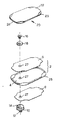
図面を参照すると、図1の組立分解図には、トレイ状の電極キャリア4、電極プロパー6、および電極キャリア4を副子(図示せず)に取り付けるために使用する両面接着パッチ8で構成された電極ユニット2が見える。以下でさらに説明するように、電極6は固定状態でキャリア4に取り付けられる。副子の内面に装着するためのねじ付き突起12、および円錐状に座ぐられたねじ穴14を有する金属アダプタ10も見える。電極ユニット2は、皿小ねじ16および円錐形ワッシャ18によって副子の表面に締め付けられる。電極ユニット2は、副子の湾曲した表面に適合するよう十分に可撓性がなければならないことは明白である。
【0008】
パッド22と、4つのフラップ25を有してパッドを担持する補剛フレーム24とで構成されたパッド・ユニット20も見える。構成要素4から24に関するさらに詳細な説明は、以下にある。電極ユニット2を装着した後、孔27をあける。
【0009】
図2は、キャリア4および電極6で構成された電極ユニット2を示す。キャリア4は、図1で最もよく分かるようにトレイ状の形状と、4つの隅パッド26とを有し、これは図4で分かるように、キャリア4の表面に対して偏り、狭く開いたスリット28を生じる。以下でさらに説明するように、隅パッド26は、パッド・ユニット20を保持するが、その簡単な除去も可能にする働きをする。
【0010】
電極6は、細かいステンレス鋼の金網で作成され、超音波溶着によってキャリア4に取り付けられる。溶着シームの好ましいパターンを点線30で示す。対向して配置された2つの矢印状のマーク32も見え、これは副子内で電極ユニット2を正確に配置するのに役立つ。
【0011】
電極キャリア4は、ポリプロピレンとポリビニルの混合物を使用したプラスチック成型品であると有利である。キャリア4の後側が図3で見られ、これは既にキャリア4に装着されている接着パッチ8を示す。
【0012】
図5は、パッド・ユニット20を提示する。4つのフラップ25を有するフレーム24が見え、図6で示されるように、これはフレーム24の他の部分より厚さが薄い。パッド・ユニット20を電極ユニット2に装着するため、ここのスリット28(図4)に滑り込ませるのは、これらフラップ25である。
【0013】
パッド22は、不織布ビスコースで作成すると有利であり、これは液体、ゲルなどを吸収し、効果的な伝導媒体を提供する。特殊な型を使用して、フレーム24を予め切断したビスコース・パッドに射出成形する。毛羽立ちを防止するため、患者の皮膚に接触するパッド表面には、吸収性を有意の程度に低下させることなく、繊維を相互に結合する合成ゴム溶液を含浸させる。
【0014】
パッド・ユニット20を電極キャリア4に結合する独特の方法のため、パッド・ユニット20は、片手しか使用せずに簡単かつ迅速に取り外し、交換される。
【0015】
本発明は、以上で図示した実施形態に制限されるものではなく、本発明はその精神または基本的属性から逸脱することなく、他の特定の形態で実現できることが、当業者には明白である。したがって、本発明の実施形態は、あらゆる態様で例示的であり、非制限的と見なされ、本発明の範囲は、以上の説明ではなく請求の範囲によって指示されるものであり、請求の範囲と同等の意味および範囲に入る変更はすべて、それに含まれるものとする。
【図面の簡単な説明】
【図1】本発明による電極キットの組立分解図である。
【図2】電極ユニットの上面図である。
【図3】図2に示したユニットの背面図を示す。
【図4】電極キャリアの隅の非常に拡大した斜視図である。
【図5】パッド・ユニットの上面図である。
【図6】図5の面VI−VIに沿った断面図である。
【符号の説明】
2 電極ユニット
4 電極キャリア
6 電極プロパー
8 両面接着パッチ
10 金属アダプタ
12 ねじ付き突起
14 ねじ穴
16 皿小ねじ
18 ワッシャ
20 パッド・ユニット
22 パッド
24 フレーム
26 隅パッド
27 穴
28 スリット
30 溶着シームの好ましいパターン
32 矢印状マーク[0001]
BACKGROUND OF THE INVENTION
The present invention relates to a muscle stimulation electrode kit for use in combination with a splint.
Such splints are used to electrically stimulate limbs paralyzed with exercise therapy (TES) and generate limb function (FES).
[0002]
[Prior art]
The electrodes of these devices typically comprise a base member attached to the inside of the splint and a pad constructed of a liquid absorbent material, which pad constitutes a binder between the electrode and the patient's skin surface. . The position of the electrode relative to the muscle movement point to be stimulated is permanent and determined by the clinician, but the pad must be designed to facilitate rapid and easy removal and replacement, and for such replacement It is better not to use two or more hands.
[0003]
In many of the known TES and FES devices, dry pad replacement is a very complex process that makes it difficult for patients with only one functioning arm and hand to perform this task themselves. Need help from a caregiver. Also, the position of the pad relative to the electrode is not always clearly defined, and misalignment occurs between the electrode and the motion point, which is likely to cause an undesirable excessive flow of electrical stimulation.
[0004]
[Problems to be solved by the invention]
Accordingly, it is an object of the present invention to provide an electrode kit that not only facilitates simple removal and replacement of the pads, but also ensures accurate reproducibility of the pad position relative to the motion point.
[0005]
[Means for Solving the Problems]
According to the present invention, the above objective is accomplished by providing a muscle stimulation electrode kit for use in combination with a splint, which can be attached to the inner surface of the splint and is relatively thin and flexible. An electrode carrier composed of a tray-like member, a thin and flexible electrode member fixedly attached to the electrode, and a piece of liquid absorbent material fixed to a stiffening frame that can be attached to and detached from the electrode carrier And a skin contact pad member.
The present invention will now be described with respect to certain preferred embodiments with reference to the following illustrative figures so that it may be better understood.
[0006]
Reference will now be made in detail to the drawings, wherein the illustrated details are exemplary only and are for the purpose of exemplifying preferred embodiments of the invention in the course of which: It is emphasized that the conceptual aspects are presented to provide what appears to be the most useful and easily understood explanation. In this regard, no more detail is shown than is necessary to understand the basics of the invention, and it is not intended to illustrate the structural details of the invention. The methods that can be implemented are considered together with the drawings in order to be clear.
[0007]
DETAILED DESCRIPTION OF THE INVENTION
Referring to the drawings, the exploded view of FIG. 1 comprises a tray-
[0008]
Also visible is a
[0009]
FIG. 2 shows an
[0010]
The
[0011]
The
[0012]
FIG. 5 presents the
[0013]
The
[0014]
Due to the unique way of coupling the
[0015]
It will be apparent to those skilled in the art that the present invention is not limited to the embodiments illustrated above, and that the present invention can be implemented in other specific forms without departing from the spirit or basic attributes thereof. . Accordingly, the embodiments of the invention are to be considered in all respects as illustrative and not restrictive, the scope of the invention being indicated by the claims rather than the foregoing description, and the claims and All changes that fall within the equivalent meaning and scope are intended to be included.
[Brief description of the drawings]
FIG. 1 is an exploded view of an electrode kit according to the present invention.
FIG. 2 is a top view of the electrode unit.
3 shows a rear view of the unit shown in FIG. 2. FIG.
FIG. 4 is a very enlarged perspective view of a corner of an electrode carrier.
FIG. 5 is a top view of the pad unit.
6 is a cross-sectional view taken along plane VI-VI in FIG. 5;
[Explanation of symbols]
2
Claims (9)
前記キットは、
前記副子の内面に取り付けることができ、可撓性のトレイ状部材と、保持スリットを有する隅パッドと、を有する電極キャリアと、
前記電極キャリアに固定状態で取り付ける薄い可撓性の電極部材と、
前記電極キャリアに着脱可能な補剛フレーム上に固定状態で装着され、媒体吸収性材料で構成され、前記補剛フレームが第一の厚さを有する領域と前記第一の厚さより薄く前記保持スリットに受け入れ可能な第二の厚さを有する領域とを有した、皮膚と接触するパッド部材とを備える電極キット。A muscle stimulation electrode kit used in combination with a splint,
The kit is
An electrode carrier that can be attached to the inner surface of the splint and has a flexible tray-like member and a corner pad having a holding slit ;
A thin flexible electrode member fixedly attached to the electrode carrier;
Mounted in a fixed state on a stiffening frame that can be attached to and detached from the electrode carrier, and is made of a medium-absorbing material. The stiffening frame has a first thickness and a thickness that is thinner than the first thickness. And a pad member in contact with the skin having a region having a second thickness acceptable to the electrode kit.
Applications Claiming Priority (2)
| Application Number | Priority Date | Filing Date | Title |
|---|---|---|---|
| IL13517500A IL135175A0 (en) | 2000-03-20 | 2000-03-20 | Electrode for muscle stimulation |
| IL135175 | 2000-03-20 |
Publications (3)
| Publication Number | Publication Date |
|---|---|
| JP2001293096A JP2001293096A (en) | 2001-10-23 |
| JP2001293096A5 JP2001293096A5 (en) | 2008-05-01 |
| JP4287067B2 true JP4287067B2 (en) | 2009-07-01 |
Family
ID=11073960
Family Applications (1)
| Application Number | Title | Priority Date | Filing Date |
|---|---|---|---|
| JP2001080887A Expired - Fee Related JP4287067B2 (en) | 2000-03-20 | 2001-03-21 | Muscle stimulation electrode |
Country Status (10)
| Country | Link |
|---|---|
| US (1) | US6567706B2 (en) |
| EP (1) | EP1136096B1 (en) |
| JP (1) | JP4287067B2 (en) |
| AT (1) | ATE290901T1 (en) |
| AU (1) | AU771792B2 (en) |
| CA (1) | CA2341097C (en) |
| DE (1) | DE60018701T2 (en) |
| ES (1) | ES2238975T3 (en) |
| IL (1) | IL135175A0 (en) |
| NO (1) | NO318738B1 (en) |
Families Citing this family (26)
| Publication number | Priority date | Publication date | Assignee | Title |
|---|---|---|---|---|
| US20020193861A1 (en) * | 2001-05-30 | 2002-12-19 | Harrison Steven Michael | A.C.-powered, user-manipulate-able electrodes for stimulating living tissue |
| US7979137B2 (en) * | 2004-02-11 | 2011-07-12 | Ethicon, Inc. | System and method for nerve stimulation |
| US8165695B2 (en) * | 2004-02-11 | 2012-04-24 | Ethicon, Inc. | System and method for selectively stimulating different body parts |
| US8751003B2 (en) * | 2004-02-11 | 2014-06-10 | Ethicon, Inc. | Conductive mesh for neurostimulation |
| TWI257863B (en) * | 2004-10-29 | 2006-07-11 | Ind Tech Res Inst | Flexible electronic acupuncture device and method |
| US8588930B2 (en) | 2005-06-07 | 2013-11-19 | Ethicon, Inc. | Piezoelectric stimulation device |
| WO2007042627A1 (en) * | 2005-10-14 | 2007-04-19 | Sport Elec Sa | Electrode module for muscle maintenance and/or muscle development |
| US7899556B2 (en) * | 2005-11-16 | 2011-03-01 | Bioness Neuromodulation Ltd. | Orthosis for a gait modulation system |
| US8972017B2 (en) | 2005-11-16 | 2015-03-03 | Bioness Neuromodulation Ltd. | Gait modulation system and method |
| US8209022B2 (en) | 2005-11-16 | 2012-06-26 | Bioness Neuromodulation Ltd. | Gait modulation system and method |
| EP2012669B1 (en) | 2006-05-01 | 2013-03-13 | Bioness Neuromodulation Ltd | Improved functional electrical stimulation systems |
| DE102007046886B4 (en) * | 2007-09-28 | 2010-07-29 | Dieter Miehlich | EMS garment and electrode as well as EMS module for it |
| US8352026B2 (en) * | 2007-10-03 | 2013-01-08 | Ethicon, Inc. | Implantable pulse generators and methods for selective nerve stimulation |
| WO2009098651A1 (en) | 2008-02-05 | 2009-08-13 | Compex Medical S.A. | Stimulation brace |
| US8548558B2 (en) * | 2008-03-06 | 2013-10-01 | Covidien Lp | Electrode capable of attachment to a garment, system, and methods of manufacturing |
| US20090227857A1 (en) * | 2008-03-06 | 2009-09-10 | Chuck Rowe | Biomedical electrode |
| US8868216B2 (en) * | 2008-11-21 | 2014-10-21 | Covidien Lp | Electrode garment |
| TW201023770A (en) * | 2008-12-25 | 2010-07-01 | Arbl Co Ltd | Female underwear capable of providing local stimulation and displaying stimulation effect |
| JP5565862B2 (en) * | 2010-06-29 | 2014-08-06 | 株式会社日本メディックス | Electrode device in electrical stimulator |
| US9095417B2 (en) | 2011-02-07 | 2015-08-04 | Bioness Neuromodulation Ltd. | Adjustable orthosis for electrical stimulation of a limb |
| US8868217B2 (en) * | 2011-06-27 | 2014-10-21 | Bioness Neuromodulation Ltd. | Electrode for muscle stimulation |
| CA2942750C (en) | 2013-03-15 | 2022-06-28 | Neurolief Ltd. | Headset for treatment and assessment of medical conditions |
| US9867985B2 (en) | 2014-03-24 | 2018-01-16 | Bioness Inc. | Systems and apparatus for gait modulation and methods of use |
| EP3402404B1 (en) | 2016-01-11 | 2021-07-21 | Bioness Inc. | Apparatus for gait modulation |
| CN106693162A (en) * | 2017-03-06 | 2017-05-24 | 桂林市威诺敦医疗器械有限公司 | Quick installation electrode slice device |
| WO2021178040A1 (en) * | 2020-03-03 | 2021-09-10 | Garwood Medical Devices, Llc | Circumferentially wrappable electrode for use with metal surgical implants |
Family Cites Families (14)
| Publication number | Priority date | Publication date | Assignee | Title |
|---|---|---|---|---|
| US3610250A (en) * | 1967-01-10 | 1971-10-05 | Robert I Sarbacher | Electrical contact-carrying garment for muscle stimulation |
| CH649471A5 (en) * | 1980-05-09 | 1985-05-31 | Leuenberger H | ELECTROTHERAPEUTIC DEVICE WITH AN ELECTRODE ATTACHABLE TO A BODY PLACE COVERED BY THE PLASTERING. |
| US4699146A (en) * | 1982-02-25 | 1987-10-13 | Valleylab, Inc. | Hydrophilic, elastomeric, pressure-sensitive adhesive |
| IL97701A (en) * | 1991-03-28 | 1995-06-29 | Univ Ben Gurion | Device for generating hand function |
| GB2261290B (en) * | 1991-11-07 | 1995-09-20 | Alan Remy Magill | Health monitoring |
| US5397338A (en) * | 1993-03-29 | 1995-03-14 | Maven Labs, Inc. | Electrotherapy device |
| IL111396A (en) * | 1994-10-25 | 1997-07-13 | Ness Neuromuscular Electrical Stimulation Systems Ltd | Electrode system |
| US6064912A (en) * | 1997-03-28 | 2000-05-16 | Kenney; John P. | Orthotic/electrotherapy for treating contractures due to immobility |
| WO1998053877A1 (en) * | 1997-05-30 | 1998-12-03 | Neuromotion Inc. | Assembly for holding electrodes of a functional electrical stimulation device |
| US6038464A (en) * | 1998-02-09 | 2000-03-14 | Axelgaard Manufacturing Co., Ltd. | Medical electrode |
| US5974344A (en) * | 1998-03-02 | 1999-10-26 | Shoemaker, Ii; Charles | Wound care electrode |
| US6212435B1 (en) * | 1998-11-13 | 2001-04-03 | Respironics, Inc. | Intraoral electromuscular stimulation device and method |
| US6341237B1 (en) * | 1999-10-25 | 2002-01-22 | Arthur F. Hurtado | Device for administrating electro-muscle stimulation and method of use |
| US6438428B1 (en) * | 1999-10-27 | 2002-08-20 | Axelgaard Manufacturing Co., Ltd. | Electrical stimulation compress |
-
2000
- 2000-03-20 IL IL13517500A patent/IL135175A0/en unknown
- 2000-11-10 ES ES00310005T patent/ES2238975T3/en not_active Expired - Lifetime
- 2000-11-10 EP EP00310005A patent/EP1136096B1/en not_active Expired - Lifetime
- 2000-11-10 DE DE60018701T patent/DE60018701T2/en not_active Expired - Lifetime
- 2000-11-10 AT AT00310005T patent/ATE290901T1/en not_active IP Right Cessation
-
2001
- 2001-03-16 NO NO20011332A patent/NO318738B1/en not_active IP Right Cessation
- 2001-03-19 CA CA2341097A patent/CA2341097C/en not_active Expired - Fee Related
- 2001-03-19 AU AU28107/01A patent/AU771792B2/en not_active Ceased
- 2001-03-20 US US09/811,613 patent/US6567706B2/en not_active Expired - Lifetime
- 2001-03-21 JP JP2001080887A patent/JP4287067B2/en not_active Expired - Fee Related
Also Published As
| Publication number | Publication date |
|---|---|
| US6567706B2 (en) | 2003-05-20 |
| US20010039444A1 (en) | 2001-11-08 |
| ATE290901T1 (en) | 2005-04-15 |
| AU2810701A (en) | 2001-09-27 |
| CA2341097C (en) | 2010-05-11 |
| EP1136096A1 (en) | 2001-09-26 |
| AU771792B2 (en) | 2004-04-01 |
| NO20011332L (en) | 2001-09-21 |
| CA2341097A1 (en) | 2001-09-20 |
| DE60018701T2 (en) | 2006-04-06 |
| ES2238975T3 (en) | 2005-09-16 |
| EP1136096B1 (en) | 2005-03-16 |
| NO20011332D0 (en) | 2001-03-16 |
| DE60018701D1 (en) | 2005-04-21 |
| IL135175A0 (en) | 2001-05-20 |
| NO318738B1 (en) | 2005-05-02 |
| JP2001293096A (en) | 2001-10-23 |
Similar Documents
| Publication | Publication Date | Title |
|---|---|---|
| JP4287067B2 (en) | Muscle stimulation electrode | |
| EP2723442B1 (en) | Electrode for muscle stimulation | |
| ATE278354T1 (en) | HOLTER-TYPE DEVICE FOR RECORDING PHYSIOLOGICAL SIGNALS OF CARDIAC ACTIVITY | |
| JP2004531351A (en) | Hydrogel and scrim assembly used with electroacupuncture device with stimulation electrode | |
| JPH04501224A (en) | Improved removable sensor support | |
| CN103519935A (en) | Disposable electric vibration patch | |
| CN211383470U (en) | Pulse electric thumb-tack needle | |
| JP2004057453A (en) | Director for stimulating organism | |
| TW473396B (en) | Low frequency generating poultice | |
| WO2019148073A1 (en) | Reducing pain at a medical treatment site | |
| CN214910492U (en) | Acupuncture box with dust removal function | |
| CN211535637U (en) | Medical acupuncture auxiliary positioning device | |
| CN210812495U (en) | Portable traditional Chinese medicine acupoint rehabilitation therapeutic apparatus | |
| JPH063615Y2 (en) | Low frequency therapy device | |
| KR200241536Y1 (en) | Arm board for injecting set | |
| CN1410136A (en) | Therapeutic paster capable of passing light, guiding medicine, magnetic inducting and electric conducting | |
| JP2981619B2 (en) | Needle removal device | |
| JPH1156581A (en) | Auxiliary device at the time of replacing diaper for baby | |
| JP3024632U (en) | Acupuncture set | |
| AU2012277312B2 (en) | Electrode for muscle stimulation | |
| RU2007986C1 (en) | Device for electropuncture | |
| JPH065802Y2 (en) | Electrotherapy device conductor | |
| IT1144074B (en) | Disposable medical electrode | |
| RU2000110796A (en) | ELECTRODE FOR FEEDING SKIN WITH ELECTRIC CURRENT FOR PHYSIOTHERAPY | |
| JP2001161710A (en) | Auxiliary instrument for pus tray |
Legal Events
| Date | Code | Title | Description |
|---|---|---|---|
| A521 | Request for written amendment filed |
Free format text: JAPANESE INTERMEDIATE CODE: A523 Effective date: 20080318 |
|
| A621 | Written request for application examination |
Free format text: JAPANESE INTERMEDIATE CODE: A621 Effective date: 20080318 |
|
| A131 | Notification of reasons for refusal |
Free format text: JAPANESE INTERMEDIATE CODE: A131 Effective date: 20080806 |
|
| A601 | Written request for extension of time |
Free format text: JAPANESE INTERMEDIATE CODE: A601 Effective date: 20081106 |
|
| A602 | Written permission of extension of time |
Free format text: JAPANESE INTERMEDIATE CODE: A602 Effective date: 20081111 |
|
| A601 | Written request for extension of time |
Free format text: JAPANESE INTERMEDIATE CODE: A601 Effective date: 20081208 |
|
| A602 | Written permission of extension of time |
Free format text: JAPANESE INTERMEDIATE CODE: A602 Effective date: 20081211 |
|
| A521 | Request for written amendment filed |
Free format text: JAPANESE INTERMEDIATE CODE: A523 Effective date: 20090123 |
|
| TRDD | Decision of grant or rejection written | ||
| A01 | Written decision to grant a patent or to grant a registration (utility model) |
Free format text: JAPANESE INTERMEDIATE CODE: A01 Effective date: 20090302 |
|
| A01 | Written decision to grant a patent or to grant a registration (utility model) |
Free format text: JAPANESE INTERMEDIATE CODE: A01 |
|
| A61 | First payment of annual fees (during grant procedure) |
Free format text: JAPANESE INTERMEDIATE CODE: A61 Effective date: 20090326 |
|
| FPAY | Renewal fee payment (event date is renewal date of database) |
Free format text: PAYMENT UNTIL: 20120403 Year of fee payment: 3 |
|
| R150 | Certificate of patent or registration of utility model |
Free format text: JAPANESE INTERMEDIATE CODE: R150 |
|
| FPAY | Renewal fee payment (event date is renewal date of database) |
Free format text: PAYMENT UNTIL: 20120403 Year of fee payment: 3 |
|
| FPAY | Renewal fee payment (event date is renewal date of database) |
Free format text: PAYMENT UNTIL: 20130403 Year of fee payment: 4 |
|
| FPAY | Renewal fee payment (event date is renewal date of database) |
Free format text: PAYMENT UNTIL: 20130403 Year of fee payment: 4 |
|
| FPAY | Renewal fee payment (event date is renewal date of database) |
Free format text: PAYMENT UNTIL: 20140403 Year of fee payment: 5 |
|
| R250 | Receipt of annual fees |
Free format text: JAPANESE INTERMEDIATE CODE: R250 |
|
| R250 | Receipt of annual fees |
Free format text: JAPANESE INTERMEDIATE CODE: R250 |
|
| R250 | Receipt of annual fees |
Free format text: JAPANESE INTERMEDIATE CODE: R250 |
|
| R250 | Receipt of annual fees |
Free format text: JAPANESE INTERMEDIATE CODE: R250 |
|
| LAPS | Cancellation because of no payment of annual fees |