EP3402404B1 - Apparatus for gait modulation - Google Patents
Apparatus for gait modulation Download PDFInfo
- Publication number
- EP3402404B1 EP3402404B1 EP17738843.6A EP17738843A EP3402404B1 EP 3402404 B1 EP3402404 B1 EP 3402404B1 EP 17738843 A EP17738843 A EP 17738843A EP 3402404 B1 EP3402404 B1 EP 3402404B1
- Authority
- EP
- European Patent Office
- Prior art keywords
- electrode
- electrodes
- connector
- limb
- orthosis
- Prior art date
- Legal status (The legal status is an assumption and is not a legal conclusion. Google has not performed a legal analysis and makes no representation as to the accuracy of the status listed.)
- Active
Links
- 230000005021 gait Effects 0.000 title claims description 77
- 230000000638 stimulation Effects 0.000 claims description 340
- 230000002232 neuromuscular Effects 0.000 claims description 149
- 238000004891 communication Methods 0.000 claims description 55
- 230000033001 locomotion Effects 0.000 claims description 52
- 239000000463 material Substances 0.000 claims description 33
- 230000000694 effects Effects 0.000 claims description 24
- 230000007935 neutral effect Effects 0.000 claims description 17
- 230000000295 complement effect Effects 0.000 claims description 15
- 230000001351 cycling effect Effects 0.000 claims description 9
- 210000003414 extremity Anatomy 0.000 description 275
- 210000002414 leg Anatomy 0.000 description 99
- 210000002683 foot Anatomy 0.000 description 77
- 230000008878 coupling Effects 0.000 description 52
- 238000010168 coupling process Methods 0.000 description 52
- 238000005859 coupling reaction Methods 0.000 description 52
- 210000003205 muscle Anatomy 0.000 description 41
- 210000001519 tissue Anatomy 0.000 description 32
- 210000000689 upper leg Anatomy 0.000 description 30
- 230000001771 impaired effect Effects 0.000 description 29
- 230000006870 function Effects 0.000 description 27
- 210000005036 nerve Anatomy 0.000 description 23
- 230000007246 mechanism Effects 0.000 description 18
- 238000000034 method Methods 0.000 description 18
- 230000000712 assembly Effects 0.000 description 17
- 238000000429 assembly Methods 0.000 description 17
- 210000003141 lower extremity Anatomy 0.000 description 17
- 239000004744 fabric Substances 0.000 description 14
- 210000001364 upper extremity Anatomy 0.000 description 14
- 230000000007 visual effect Effects 0.000 description 14
- 210000003127 knee Anatomy 0.000 description 12
- 230000004044 response Effects 0.000 description 12
- 230000001976 improved effect Effects 0.000 description 11
- 230000036541 health Effects 0.000 description 9
- 210000001699 lower leg Anatomy 0.000 description 9
- 230000002829 reductive effect Effects 0.000 description 9
- 210000002972 tibial nerve Anatomy 0.000 description 9
- 239000000017 hydrogel Substances 0.000 description 8
- 210000004345 peroneal nerve Anatomy 0.000 description 8
- -1 polypropylene Polymers 0.000 description 8
- 210000003314 quadriceps muscle Anatomy 0.000 description 8
- 229920002334 Spandex Polymers 0.000 description 7
- 230000004913 activation Effects 0.000 description 7
- 239000012811 non-conductive material Substances 0.000 description 7
- 239000004743 Polypropylene Substances 0.000 description 6
- 210000003484 anatomy Anatomy 0.000 description 6
- 229920001155 polypropylene Polymers 0.000 description 6
- 239000000853 adhesive Substances 0.000 description 5
- 230000001070 adhesive effect Effects 0.000 description 5
- 230000008859 change Effects 0.000 description 5
- 239000002184 metal Substances 0.000 description 5
- 239000004759 spandex Substances 0.000 description 5
- XLYOFNOQVPJJNP-UHFFFAOYSA-N water Substances O XLYOFNOQVPJJNP-UHFFFAOYSA-N 0.000 description 5
- 210000003423 ankle Anatomy 0.000 description 4
- 201000010099 disease Diseases 0.000 description 4
- 208000037265 diseases, disorders, signs and symptoms Diseases 0.000 description 4
- 230000002708 enhancing effect Effects 0.000 description 4
- 210000001624 hip Anatomy 0.000 description 4
- 208000014674 injury Diseases 0.000 description 4
- 230000008569 process Effects 0.000 description 4
- 230000001737 promoting effect Effects 0.000 description 4
- 210000003497 sciatic nerve Anatomy 0.000 description 4
- 206010019196 Head injury Diseases 0.000 description 3
- 208000006011 Stroke Diseases 0.000 description 3
- 230000005540 biological transmission Effects 0.000 description 3
- 230000010267 cellular communication Effects 0.000 description 3
- 230000001413 cellular effect Effects 0.000 description 3
- 206010008129 cerebral palsy Diseases 0.000 description 3
- 239000004020 conductor Substances 0.000 description 3
- 230000006378 damage Effects 0.000 description 3
- 230000006735 deficit Effects 0.000 description 3
- 230000001066 destructive effect Effects 0.000 description 3
- 230000001965 increasing effect Effects 0.000 description 3
- 238000004519 manufacturing process Methods 0.000 description 3
- 239000012528 membrane Substances 0.000 description 3
- 201000006417 multiple sclerosis Diseases 0.000 description 3
- 210000004417 patella Anatomy 0.000 description 3
- 230000037081 physical activity Effects 0.000 description 3
- 229920000642 polymer Polymers 0.000 description 3
- 239000011148 porous material Substances 0.000 description 3
- 208000020431 spinal cord injury Diseases 0.000 description 3
- 229920001169 thermoplastic Polymers 0.000 description 3
- 239000004416 thermosoftening plastic Substances 0.000 description 3
- 238000012549 training Methods 0.000 description 3
- 230000003442 weekly effect Effects 0.000 description 3
- 239000004677 Nylon Substances 0.000 description 2
- 229920000297 Rayon Polymers 0.000 description 2
- 208000030886 Traumatic Brain injury Diseases 0.000 description 2
- 208000027418 Wounds and injury Diseases 0.000 description 2
- 230000002745 absorbent Effects 0.000 description 2
- 239000002250 absorbent Substances 0.000 description 2
- 230000004888 barrier function Effects 0.000 description 2
- 210000003169 central nervous system Anatomy 0.000 description 2
- 230000008602 contraction Effects 0.000 description 2
- 230000003247 decreasing effect Effects 0.000 description 2
- 238000013461 design Methods 0.000 description 2
- 238000009826 distribution Methods 0.000 description 2
- 238000005516 engineering process Methods 0.000 description 2
- 210000003099 femoral nerve Anatomy 0.000 description 2
- 239000012530 fluid Substances 0.000 description 2
- 239000000499 gel Substances 0.000 description 2
- 239000007788 liquid Substances 0.000 description 2
- 238000005259 measurement Methods 0.000 description 2
- 229920001778 nylon Polymers 0.000 description 2
- 230000036961 partial effect Effects 0.000 description 2
- 229920001296 polysiloxane Polymers 0.000 description 2
- 238000012545 processing Methods 0.000 description 2
- 230000000717 retained effect Effects 0.000 description 2
- 230000002441 reversible effect Effects 0.000 description 2
- 229920006395 saturated elastomer Polymers 0.000 description 2
- 230000008054 signal transmission Effects 0.000 description 2
- 239000007779 soft material Substances 0.000 description 2
- 230000004936 stimulating effect Effects 0.000 description 2
- 239000012815 thermoplastic material Substances 0.000 description 2
- 230000007704 transition Effects 0.000 description 2
- 230000008733 trauma Effects 0.000 description 2
- 230000009529 traumatic brain injury Effects 0.000 description 2
- CGPYNUAPVFBCFD-UHFFFAOYSA-N C1C2OCCC12 Chemical compound C1C2OCCC12 CGPYNUAPVFBCFD-UHFFFAOYSA-N 0.000 description 1
- 206010021118 Hypotonia Diseases 0.000 description 1
- 208000008238 Muscle Spasticity Diseases 0.000 description 1
- 230000001133 acceleration Effects 0.000 description 1
- 230000009471 action Effects 0.000 description 1
- 230000003213 activating effect Effects 0.000 description 1
- 210000000544 articulatio talocruralis Anatomy 0.000 description 1
- 208000020538 atrophic muscular disease Diseases 0.000 description 1
- 230000009286 beneficial effect Effects 0.000 description 1
- 239000000560 biocompatible material Substances 0.000 description 1
- 230000017531 blood circulation Effects 0.000 description 1
- 208000029028 brain injury Diseases 0.000 description 1
- 238000010276 construction Methods 0.000 description 1
- 238000012937 correction Methods 0.000 description 1
- 230000001419 dependent effect Effects 0.000 description 1
- 238000006073 displacement reaction Methods 0.000 description 1
- 230000009977 dual effect Effects 0.000 description 1
- 239000013013 elastic material Substances 0.000 description 1
- 239000011888 foil Substances 0.000 description 1
- 238000010438 heat treatment Methods 0.000 description 1
- 230000006872 improvement Effects 0.000 description 1
- 230000000977 initiatory effect Effects 0.000 description 1
- 210000000629 knee joint Anatomy 0.000 description 1
- 210000003041 ligament Anatomy 0.000 description 1
- 239000004973 liquid crystal related substance Substances 0.000 description 1
- 230000013011 mating Effects 0.000 description 1
- 238000012544 monitoring process Methods 0.000 description 1
- 230000004118 muscle contraction Effects 0.000 description 1
- 230000036640 muscle relaxation Effects 0.000 description 1
- 230000003287 optical effect Effects 0.000 description 1
- 230000007170 pathology Effects 0.000 description 1
- 230000001766 physiological effect Effects 0.000 description 1
- 230000035945 sensitivity Effects 0.000 description 1
- 230000001953 sensory effect Effects 0.000 description 1
- 210000002265 sensory receptor cell Anatomy 0.000 description 1
- 102000027509 sensory receptors Human genes 0.000 description 1
- 108091008691 sensory receptors Proteins 0.000 description 1
- 208000018198 spasticity Diseases 0.000 description 1
- 230000003068 static effect Effects 0.000 description 1
- 210000004243 sweat Anatomy 0.000 description 1
- 230000021542 voluntary musculoskeletal movement Effects 0.000 description 1
- 238000003466 welding Methods 0.000 description 1
Images


Classifications
-
- A—HUMAN NECESSITIES
- A61—MEDICAL OR VETERINARY SCIENCE; HYGIENE
- A61N—ELECTROTHERAPY; MAGNETOTHERAPY; RADIATION THERAPY; ULTRASOUND THERAPY
- A61N1/00—Electrotherapy; Circuits therefor
- A61N1/18—Applying electric currents by contact electrodes
- A61N1/32—Applying electric currents by contact electrodes alternating or intermittent currents
- A61N1/36—Applying electric currents by contact electrodes alternating or intermittent currents for stimulation
- A61N1/36003—Applying electric currents by contact electrodes alternating or intermittent currents for stimulation of motor muscles, e.g. for walking assistance
-
- A—HUMAN NECESSITIES
- A61—MEDICAL OR VETERINARY SCIENCE; HYGIENE
- A61B—DIAGNOSIS; SURGERY; IDENTIFICATION
- A61B5/00—Measuring for diagnostic purposes; Identification of persons
- A61B5/103—Detecting, measuring or recording devices for testing the shape, pattern, colour, size or movement of the body or parts thereof, for diagnostic purposes
- A61B5/1036—Measuring load distribution, e.g. podologic studies
- A61B5/1038—Measuring plantar pressure during gait
-
- A—HUMAN NECESSITIES
- A61—MEDICAL OR VETERINARY SCIENCE; HYGIENE
- A61B—DIAGNOSIS; SURGERY; IDENTIFICATION
- A61B5/00—Measuring for diagnostic purposes; Identification of persons
- A61B5/103—Detecting, measuring or recording devices for testing the shape, pattern, colour, size or movement of the body or parts thereof, for diagnostic purposes
- A61B5/11—Measuring movement of the entire body or parts thereof, e.g. head or hand tremor, mobility of a limb
- A61B5/112—Gait analysis
-
- A—HUMAN NECESSITIES
- A61—MEDICAL OR VETERINARY SCIENCE; HYGIENE
- A61B—DIAGNOSIS; SURGERY; IDENTIFICATION
- A61B5/00—Measuring for diagnostic purposes; Identification of persons
- A61B5/68—Arrangements of detecting, measuring or recording means, e.g. sensors, in relation to patient
- A61B5/6801—Arrangements of detecting, measuring or recording means, e.g. sensors, in relation to patient specially adapted to be attached to or worn on the body surface
- A61B5/6802—Sensor mounted on worn items
- A61B5/6811—External prosthesis
-
- A—HUMAN NECESSITIES
- A61—MEDICAL OR VETERINARY SCIENCE; HYGIENE
- A61B—DIAGNOSIS; SURGERY; IDENTIFICATION
- A61B5/00—Measuring for diagnostic purposes; Identification of persons
- A61B5/68—Arrangements of detecting, measuring or recording means, e.g. sensors, in relation to patient
- A61B5/6801—Arrangements of detecting, measuring or recording means, e.g. sensors, in relation to patient specially adapted to be attached to or worn on the body surface
- A61B5/6813—Specially adapted to be attached to a specific body part
- A61B5/6828—Leg
-
- A—HUMAN NECESSITIES
- A61—MEDICAL OR VETERINARY SCIENCE; HYGIENE
- A61N—ELECTROTHERAPY; MAGNETOTHERAPY; RADIATION THERAPY; ULTRASOUND THERAPY
- A61N1/00—Electrotherapy; Circuits therefor
- A61N1/02—Details
- A61N1/04—Electrodes
- A61N1/0404—Electrodes for external use
- A61N1/0408—Use-related aspects
- A61N1/0452—Specially adapted for transcutaneous muscle stimulation [TMS]
-
- A—HUMAN NECESSITIES
- A61—MEDICAL OR VETERINARY SCIENCE; HYGIENE
- A61N—ELECTROTHERAPY; MAGNETOTHERAPY; RADIATION THERAPY; ULTRASOUND THERAPY
- A61N1/00—Electrotherapy; Circuits therefor
- A61N1/02—Details
- A61N1/04—Electrodes
- A61N1/0404—Electrodes for external use
- A61N1/0472—Structure-related aspects
- A61N1/0484—Garment electrodes worn by the patient
-
- A—HUMAN NECESSITIES
- A61—MEDICAL OR VETERINARY SCIENCE; HYGIENE
- A61N—ELECTROTHERAPY; MAGNETOTHERAPY; RADIATION THERAPY; ULTRASOUND THERAPY
- A61N1/00—Electrotherapy; Circuits therefor
- A61N1/18—Applying electric currents by contact electrodes
- A61N1/32—Applying electric currents by contact electrodes alternating or intermittent currents
- A61N1/36—Applying electric currents by contact electrodes alternating or intermittent currents for stimulation
- A61N1/36014—External stimulators, e.g. with patch electrodes
-
- A—HUMAN NECESSITIES
- A61—MEDICAL OR VETERINARY SCIENCE; HYGIENE
- A61B—DIAGNOSIS; SURGERY; IDENTIFICATION
- A61B5/00—Measuring for diagnostic purposes; Identification of persons
- A61B5/0002—Remote monitoring of patients using telemetry, e.g. transmission of vital signals via a communication network
-
- A—HUMAN NECESSITIES
- A61—MEDICAL OR VETERINARY SCIENCE; HYGIENE
- A61B—DIAGNOSIS; SURGERY; IDENTIFICATION
- A61B5/00—Measuring for diagnostic purposes; Identification of persons
- A61B5/48—Other medical applications
- A61B5/4836—Diagnosis combined with treatment in closed-loop systems or methods
-
- A—HUMAN NECESSITIES
- A61—MEDICAL OR VETERINARY SCIENCE; HYGIENE
- A61B—DIAGNOSIS; SURGERY; IDENTIFICATION
- A61B5/00—Measuring for diagnostic purposes; Identification of persons
- A61B5/68—Arrangements of detecting, measuring or recording means, e.g. sensors, in relation to patient
- A61B5/6801—Arrangements of detecting, measuring or recording means, e.g. sensors, in relation to patient specially adapted to be attached to or worn on the body surface
- A61B5/6802—Sensor mounted on worn items
- A61B5/6804—Garments; Clothes
- A61B5/6807—Footwear
-
- A—HUMAN NECESSITIES
- A61—MEDICAL OR VETERINARY SCIENCE; HYGIENE
- A61F—FILTERS IMPLANTABLE INTO BLOOD VESSELS; PROSTHESES; DEVICES PROVIDING PATENCY TO, OR PREVENTING COLLAPSING OF, TUBULAR STRUCTURES OF THE BODY, e.g. STENTS; ORTHOPAEDIC, NURSING OR CONTRACEPTIVE DEVICES; FOMENTATION; TREATMENT OR PROTECTION OF EYES OR EARS; BANDAGES, DRESSINGS OR ABSORBENT PADS; FIRST-AID KITS
- A61F5/00—Orthopaedic methods or devices for non-surgical treatment of bones or joints; Nursing devices; Anti-rape devices
- A61F5/01—Orthopaedic devices, e.g. splints, casts or braces
Definitions
- the embodiments described herein relate generally to gait modulation systems, and more particularly, to a functional electrical stimulation (FES) system or orthosis for gait modulation.
- FES functional electrical stimulation
- Gait the biomechanical description of walking, can suffer static and dynamic parameter variations due to neuromuscular impairments, which can cause non-symmetrical walking, reduced walking speed, and/or reduced walking stability.
- drop foot describes a gait characteristic attributable to weak or uncoordinated activation of the ankle dorsiflexors due to disease or trauma to the central nervous system.
- Limb muscles can generally be activated with functional electrical stimulation (FES).
- FES functional electrical stimulation
- precisely timed bursts of short electrical pulses e.g., from a neuroprosthetic, an FES orthosis, and/or the like
- FES functional electrical stimulation
- a neuroprosthetic e.g., an FES orthosis, and/or the like
- motor nerves e.g., from a neuroprosthetic, an FES orthosis, and/or the like
- drawbacks that prevent the systems from being widely used by potential patients. For example, in instances in which stroke or brain injury results in problems with arm movement or gait, such problems are often accompanied by hand impairment on the same side of the body as the problematic limb.
- donning an FES orthosis is often carried out using solely the contra-lateral, unaffected hand.
- the posture of the plegic limb is often problematic, especially in cases where spasticity results in reduced voluntary movements and/or limited passive range of motion of the limb joints. Consequently, objective biomechanical problems exist in donning some known orthotic devices, as well as in locating the electrodes in exact positions onto the limb, which is essential for activating the desired movement pattern. As such, some known neuroprosthetic devices fail to enable facile, quick, and accurate donning of the device by an impaired patient using a single hand, and particularly, when the least effected hand is shaky or otherwise unstable.
- FES devices typically utilize a stimulator unit to create and control the electrical pulses being applied to motor nerves that is physically separate from the FES orthosis.
- the external stimulator unit which is connected to the FES orthosis by several electrical wires, is located on the body of the user and/or is otherwise worn or held by the user.
- These devices can be inconvenient for the user.
- the wiring which is usually arranged to run along the leg under the clothing to connect the device components, can be difficult to operate, cumbersome and uncomfortable.
- an FES orthosis can be a self-contained device.
- some known orthoses can include a stimulator unit coupled to a narrow band that is made of a thermoplastic material, which is molded to the limb anatomy of an individual user by heating and softening the thermoplastic material and subsequently fitting the band to the contour of the underlying limb segment.
- the shape and size of the device and the electrode positioning is custom-fitted to the leg of one user and individualized for the user. This procedure is carried out by a medical professional trained, for example, to accurately identify the stimulation points that cause contraction of the muscles, positioning and locking the electrodes thereto.
- Activation of the leg muscles by electrical stimulation typically includes transferring high stimulation currents through one or more electrodes to the skin surface of the patient, which activates skin sensory receptors in addition to underlying excitable motor nerve and muscle tissue.
- the intensity of sensory activation often depends on the intensity of the current density passing through the skin surface.
- the level of muscle activation therefore, is often limited to the patient's individual tolerance to activation of such skin pain sensors.
- the stimulation parameters tolerable by the patient may be insufficient to promote optimal movement of the impaired limb in response to the FES.
- one or more electrodes of such systems must be moved to various locations on the patient's skin until a desirable movement of the impaired limb is achieved.
- WO 2015/188889 discloses a functional electrical stimulation system for correction of drop-foot, comprising: a device to be placed on a paretic leg, provided with a plurality of multi-pad electrodes on one side, at least one of said electrodes being configured to provide a stimulating electric signal on the point of the leg on which it is positioned, wherein said corresponding stimulating electric signals form a stimulation pattern; and at least one sensor to be positioned on either said leg or corresponding foot, the sensor being configured to, measure information during movement and emit sensor signals indicative thereof.
- an apparatus in some embodiments, includes a frame assembly, an electrode assembly, and an electric stimulator.
- the frame assembly is configured to be removably coupled to a portion of a limb such that the portion of the limb is substantially enveloped by the frame.
- the electrode assembly is configured to be in electrical communication with a portion of a neuromuscular system of the limb.
- the electrode assembly is removably coupled to the frame assembly.
- the electrode assembly includes a first set of electrodes and a second set of electrodes.
- the electric stimulator is removably coupled to the frame assembly and is in electrical communication with the electrode assembly.
- the electric stimulator is configured to send a first signal substantially during a first time period and via a first channel to the first set of electrodes to provide an electrical stimulation to a neuromuscular system of the limb.
- the electric stimulator is configured to send a second signal via a second channel to the second set of electrodes to provide electrical stimulation to the neuromuscular system of the limb.
- the electric stimulator is configured to send the second signal substantially during at least one of the first time period or a second time period subsequent the first time period.
- an apparatus includes a frame assembly, an electrode assembly, and an electric stimulator.
- the frame assembly is configured to be removably coupled to a portion of a limb such that the portion of the limb is substantially enveloped by the frame.
- the electrode assembly is configured to be in electrical communication with a portion of a neuromuscular system of the limb.
- the electrode assembly is at least partially disposed between the frame assembly and the limb when the limb is substantially enveloped by the frame.
- the electrode assembly includes a first set of electrodes and a second set of electrodes.
- the electric stimulator is in electrical communication with the electrode assembly.
- the electric stimulator is configured to send a first signal substantially during a first time period and via a first channel to the first set of electrodes operable to provide an electrical stimulation to a neuromuscular system of the limb.
- the electric stimulator is configured to send a second signal via a second channel to the second set of electrodes operable to provide electrical stimulation to the neuromuscular system of the limb.
- the electric stimulator is configured to send the second signal substantially during at least one of the first time period or a second time period subsequent the first time period.
- an apparatus in some embodiments, includes a frame assembly, an electrode assembly and an electric stimulator.
- the frame assembly is configured to be removably coupled to a portion of a limb such that the portion of the limb is substantially enveloped by the frame.
- the electrode assembly is configured to be in electrical communication with a portion of a neuromuscular system of the limb.
- the electrode assembly is removably coupled to an inner surface of the frame assembly and includes a panel of flexible material and a plurality of surface electrodes coupled to the panel.
- the plurality of surface electrodes includes a set of cathodic electrodes and a set of anodic electrodes.
- the electric stimulator is removably coupled to the frame assembly.
- the electric stimulator is configured to apply a first electrical current to the electrode assembly such that the first electrical current is transmitted through bodily tissue between a first cathodic electrode from the set of cathodic electrodes and a first anodic electrode from the set of anodic electrodes.
- the electric stimulator is configured to apply a second electrical current to the electrode assembly such that the second electrical current is transmitted through bodily tissue between a second cathodic electrode from the set of cathodic electrodes and at least one of the first anodic electrode or a second anodic electrode from the set of anodic electrodes.
- a method includes sending a first signal via a first channel from an electric stimulator to an electrode assembly to cause a first set of electrodes from the electrode assembly to provide an electric stimulation having a first set of parameters substantially during a time period to a neuromuscular system of a limb.
- the first set of electrodes includes a first cathodic electrode and a first anodic electrode.
- the method also includes sending a second signal via a second channel from the electric stimulator to the electrode assembly to cause a second set of electrodes from the electrode assembly to provide an electric stimulation having a second set of parameters to the neuromuscular system of a limb.
- the electric stimulation is provided substantially during at least one of the first time period or a second time period subsequent the first time period.
- the second set of electrodes includes a second cathodic electrode and at least one of the first anodic electrode or a second anodic electrode.
- a member is intended to mean a single member or a combination of members
- a material is intended to mean one or more materials, or a combination thereof.
- limb and limb segment refer to at least a portion of a mammalian appendage.
- the embodiments described herein can be coupled to and/or otherwise placed in contact with a limb segment that can include a portion of the arm (e.g., the shoulder, upper arm, lower arm, or hand), or a portion of the leg (e.g., the hip, upper leg, lower leg, or foot) of a human body.
- envelope As used herein, the terms “envelop,” “enveloping,” and/or the like, with regard to a limb segment and an article or device coupled thereto, refer to an article or device that substantially surrounds and/or covers at least one half the circumference of a limb segment when coupled thereto. For example, if when coupled to a limb, an article or device substantially circumscribes a portion of the limb, the article or device can be said to envelop the portion of the limb.
- FES orthosis As used herein, the terms “FES orthosis,” “orthosis,” “neuroprosthetic,” “FES system,” “FES device,” “device,” and/or the like can be used interchangeably and refer generally to a medical apparatus that is selectively placed in contact with a portion of a patient or user. As described herein, such devices can include one or more electrodes that can transmit a flow of electrical current to a portion of a neuromuscular system associated with the portion of the patient or user, thereby providing functional electrical stimulation to, for example, an impaired limb.
- reversible when used to described a process and/or procedure generally refer to a non-destructive process or procedure that can be subsequently undone by a similar yet substantially opposed, inverse, and/or opposite non-destructive process or procedure.
- a reversible attachment refers to a non-destructive, repeatable attachment and/or detachment of the element or assembly.
- the term "set" can refer to multiple features or a singular feature with multiple parts.
- the set of walls can be considered as one wall with multiple portions, or the set of walls can be considered as multiple, distinct walls.
- a monolithically constructed item can include a set of walls.
- Such a set of walls may include multiple portions that are either continuous or discontinuous from each other.
- a set of walls can also be fabricated from multiple items that are produced separately and are later joined together (e.g., via a weld, an adhesive, or any suitable method).
- the terms “about” and/or “approximately” when used in conjunction with numerical values and/or ranges generally refer to those numerical values and/or ranges near to a recited numerical value and/or range.
- “about 40 [units]” can mean within ⁇ 25% of 40 (e.g., from 30 to 50).
- the terms “about” and “approximately” can mean within ⁇ 10% of the recited value.
- the terms “about” and “approximately” can mean within ⁇ 9%, ⁇ 8%, ⁇ 7%, ⁇ 6%, ⁇ 5%, ⁇ 4%, ⁇ 3%, ⁇ 2%, ⁇ 1%, less than ⁇ 1%, or any other value or range of values therein or therebelow.
- the terms “about” and “approximately” may be used interchangeably. In some instances, such as when assessing a gait phase of a stimulation parameter and/or the like, the terms “about” and “approximately” can generally mean less than plus or minus 10% of the value stated.
- a numerical value modified by the term “about” or “approximately” can allow for and/or otherwise encompass a tolerance of the stated numerical value, it is not intended to exclude the exact numerical value stated.
- term “substantially” when used in connection with, for example, a geometric relationship, a numerical value, and/or a range is intended to convey that the geometric relationship (or the structures described thereby), the number, and/or the range so defined is nominally the recited geometric relationship, number, and/or range.
- two structures described herein as being “substantially parallel” is intended to convey that, although a parallel geometric relationship is desirable, some non-parallelism can occur in a "substantially parallel” arrangement.
- a structure defining a volume that is "substantially 0.50 milliliters (mL)" is intended to convey that, while the recited volume is desirable, some tolerances can occur when the volume is “substantially” the recited volume (e.g., 0.50 mL).
- tolerances can result from manufacturing tolerances, measurement tolerances, and/or other practical considerations (such as, for example, minute imperfections, age of a structure so defined, a pressure or a force exerted within a system, and/or the like).
- a suitable tolerance can be, for example, of ⁇ 1%, ⁇ 2%, ⁇ 3%, ⁇ 4%, ⁇ 5%, ⁇ 6%, ⁇ 7%, ⁇ 8%, ⁇ 9%, ⁇ 10%, or more of the stated geometric construction, numerical value, and/or range.
- a numerical value modified by the term "substantially” can allow for and/or otherwise encompass a tolerance of the stated numerical value, it is not intended to exclude the exact numerical value stated.
- the terms “communication channel,” “communication mode,” and/or “modality” can be used interchangeably and refer generally to one or more modes of communication using, for example, one or more electronic devices. Such modes of communication can be associated with a specific format (e.g., a data unit format) that, in some instances, can be unique to that mode of communication (e.g., a different protocol, a different data unit structure or arrangement, etc.).
- a specific format e.g., a data unit format
- a cellular telephone e.g., a smart phone
- SMS short message service
- MMS multimedia message service
- WiFi® wireless fidelity
- the channel and/or modality includes, defines, and/or otherwise is associated with a data unit format suitable for transmission of data via that communication mode.
- module refers to any assembly and/or set of operatively-coupled electrical components that can include, for example, a memory, a processor, electrical traces, optical connectors, software (executing in hardware), and/or the like.
- a module executed in the processor can be any combination of hardware-based modules (e.g., a field-programmable gate array (FPGA), an application specific integrated circuit (ASIC), a digital signal processor (DSP)) and/or software-based modules (e.g., a module of computer code stored in memory and/or executed at the processor) capable of performing one or more specific functions associated with that module.
- FPGA field-programmable gate array
- ASIC application specific integrated circuit
- DSP digital signal processor
- proximal and distal refer to the direction closer to and away from, respectively, the torso of a user or wearer of a medical device.
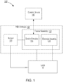
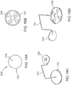
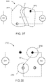
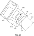
- FIG. 1 is a schematic illustration of a system 100 used for gait modulation according to an embodiment.
- the system 100 can be used by a human patient who has one or more impaired limbs as a result of injury and/or disease (e.g., stroke, spinal cord injury, head injury, traumatic brain injury, cerebral palsy, multiple sclerosis, etc.).
- the system 100 includes a functional electrical stimulation (FES) orthosis 105 (also referred to herein as "orthosis" and/or “device”) that is placed in physical and electrical contact with a limb 10 of the patient such as, for example, a lower limb segment of an impaired leg.
- FES functional electrical stimulation
- the patient and/or a health care professional can engage the system 100 in such a manner as to cause the orthosis 105 to selectively provide electrical stimulation to a portion of a neuromuscular system of the limb 10, which can, in turn, facilitate gait of the patient who might otherwise experience, for example, drop foot or the like, as described in further detail herein.
- the orthosis 105 can be configured for multiple channel stimulation of the portion of the neuromuscular system of the limb 10, as described in more detail herein. In this manner, the orthosis 105 can direct or steer a stimulation current within the portion of the neuromuscular system of the limb 10 to achieve more targeted stimulation therein to achieve improvements in the patient's gait over that which is possible using known single channel FES systems with known electrode configurations.
- the orthosis 105 is selectively operable to provide single channel stimulation, dual channel stimulation, and optionally three channel stimulation, to the portion of the neuromuscular system of the limb 10, as described in more detail herein.
- the orthosis 105 is selectively operable to provide up to six channel stimulation.
- the orthosis 105 is selectively operable to provide monopolar and/or bipolar stimulation to the portion of the neuromuscular system of the limb.
- the orthosis 105 includes a frame assembly 110, an electrode assembly 120, and an electric stimulator 140.
- at least a portion of the orthosis 105 can be substantially similar in form and function as those described in U.S. Patent No. 7,899,556 entitled, "Gait Modulation System and Method," filed April 27, 2006 (referred to henceforth as the "'556 patent"), U.S. Patent No. 8,209,036 entitled, “Gait Modulation System and Method," filed November 12, 2006 (referred to henceforth as the '"036 patent"), U.S. Patent No. 8,694,110 entitled, "Orthosis for Gait Modulation," filed June 25, 2012 (referred to henceforth as the '"110 patent"), and U.S. Patent Application Serial No. 14/223,340 entitled “Systems and Apparatus for Gait Modulation and Methods of Use,” filed March 24, 2014 (referred to henceforth as the "'340 application).
- the frame assembly 110 is configured to be removably coupled to a portion of a limb such that the portion of the limb is substantially enveloped by the frame assembly.
- a portion of the frame assembly 110 includes one or more locators configured to facilitate proper positioning of the orthosis 105 with respect to the limb of the patient.
- the locator can be formed by a recess or concavity along an edge of the frame assembly 110 such that the recess or concavity is configured to be aligned with a predetermined location of the patient's anatomy (e.g., a lower end of a patella of the patient's leg, a ridge of the tibial crest, or the like).
- an orthosis 105 includes a locator configured to provide a visual indication of the position of the orthosis, such as a line or arrow disposed thereon that should be aligned with a predetermined portion of the patient's anatomy.
- the frame assembly 110 can include one or more layers.
- at least a portion of the frame assembly 110 such as a first layer, can be formed from a semi-rigid material such as, for example, a relatively thin metal, a thermoplastic, a polymer, and/or the like, which can enable the frame assembly 110 to provide structural support for the orthosis 105.
- a first layer of the frame assembly 110 is also referred to herein as a "frame”.
- At least a portion of the frame assembly 110, such as a second or inner layer can be formed from a soft and/or flexible material, such as a nylon.
- the frame assembly 110 can be formed from a brushed fabric, a hook and/or loop material, or the like, such as those offered commercially by Nam Liong Enterprise Co., Ltd.
- the frame assembly 110 includes a third or outer layer, which can be formed, at least in part, from a flexible and/or elastic material such as elastane or spandex (such as Lycra®) or any other suitable material.
- the first layer (or frame) is disposed between the second (or inner) layer and the third (or outer) layer of the frame assembly 110.
- the frame assembly 110 is devoid of a rigid or semi-rigid layer.
- the frame assembly 110 can include one or more soft and/or flexible layers configured to be removably coupled to (or disposed about) a portion of the limb such that the portion of the limb is substantially enveloped by the frame assembly and such that the one or more soft and/or flexible layers provide the structural support for the orthosis 105.
- the layers of the frame assembly can be coupled together using any suitable coupling mechanism including, but not limited to an adhesive, welding, stitching or the like.
- the frame assembly 110 can have any suitable shape and/or size that can be, for example, associated with a segment of the limb 10 (e.g., a lower segment of a patient's leg, an upper segment of a patient's leg, a lower segment of a patient's arm, an upper segment of a patient's arm, a patient's hand). Moreover, at least a portion of the frame assembly 110 can be transitioned between a first configuration and a second configuration to couple the frame assembly 110 to the limb 10.
- a segment of the limb 10 e.g., a lower segment of a patient's leg, an upper segment of a patient's leg, a lower segment of a patient's arm, an upper segment of a patient's arm, a patient's hand.
- the frame assembly 110 can include a coupling portion or the like that can be transitioned between a first (e.g., open) configuration and a second (e.g., closed) configuration to at least temporarily couple the frame assembly 110 to the limb 10.
- a coupling portion can include one or more straps, clips, ratchets, and/or the like that can allow for facile placement and coupling of the frame assembly 110 to the limb 10, as described in further detail herein.
- the electrode assembly 120 of the orthosis 105 is coupled to an inner surface of the frame assembly 110.
- the electrode assembly 120 can be any suitable arrangement of hardware and/or software.
- the electrode assembly 120 can include one or more electrodes that are each electrically coupled to a wire, electrical trace, and/or the like that are operable in electrically coupling the one or more electrodes to the electric stimulator 140.
- at least a portion of the electrode assembly 120 can be disposed within a portion of the frame assembly 110.
- the electrode assembly can include a set of wires that are substantially enclosed by a portion of the frame assembly 110.
- at least a portion of the set of wires is disposed within or otherwise extended through an opening defined by the frame assembly 110.
- the wires can include end portions that each include a connector or the like that can, for example, be electrically coupled to the electric stimulator 140 at a first end portion and that can, for example, be electrically coupled to the electrodes at a second end portion.
- the electrode assembly 120 is electrically coupled to the electric stimulator 140 by a connector assembly, as described in more detail herein.
- the connector assembly can include a set of wires that are substantially enclosed by a portion of the frame assembly 110.
- the wires can include end portions that each include a connector or the like that can, for example, be electrically coupled to the electric stimulator 140 at a first end portion and that can, for example, be electrically coupled to the electrodes at a second end portion.
- a second end portion of each wire is electrically coupled to a connector, electrode base, or the like, configured to couple an electrode of the electrode assembly to the frame assembly 110.
- at least a portion of the connector assembly is disposed within or otherwise extended through an opening defined by the frame assembly 110.
- the electrode assembly 120 can be substantially similar in many respects in form and/or function as those described in the '556 patent, the '036 patent, the '110 patent, and/or the '340 application.
- the electrode assembly 120 includes at least one electrode configured to provide an electric stimulation to at least a portion of a neuromuscular system of the limb.
- each electrode can be engaged by the system 100, and the electric stimulator 140 particularly, to promote desired movement of the limb, such as dorsiflexion, plantarflexion, inversion, and/or eversion of the foot.
- Selective electrode activation and selective flow of electrical current via one or more channels affects the flow of the electrical current through the portion of the neuromuscular system of the limb 10, and thus can be referred to as "steering" or directing the current, or more simply "current steering".
- the orthosis 105 is configured for multi-channel stimulation of the neuromuscular system of the limb.
- the electrode assembly 120 can include any suitable number of electrodes to provide such multi-channel stimulation.
- the electrode assembly 120 includes at least three electrodes.
- the electrode assembly 120 can include two cathodic electrodes and one anodic electrode.
- an electrical current can flow via a first channel (e.g., from the electric stimulator 140) such that stimulation is provided to the portion of the neuromuscular system of the limb 10 between a first cathodic electrode and the anodic electrode, and electrical current can flow via a second channel such that stimulation is provided to the portion of the neuromuscular system of the limb 10 between a second cathodic electrode and the anodic electrode, as described in more detail herein.
- the electrode assembly 120 can include two anodic electrodes and one cathodic electrode, which can similarly provide electrical stimulation via two channels.
- the orthosis 105 can be configured for multi-channel stimulation such that at least one electrode of the electrode assembly 120 is used to deliver stimulation via at least two different channels. In this manner, the electrode assembly 120 can include at least one electrode that is shared between two or more stimulation channels during FES using the orthosis 105.
- the electrode assembly 120 includes four, five, six, or more electrodes.
- the electrode assembly 120 can include two cathodic electrodes and two anodic electrodes.
- an electrical current can flow via a first channel (e.g., from the electric stimulator 140) such that stimulation is provided to the portion of the neuromuscular system of the limb 10 between a first cathodic electrode and a first anodic electrode, and electrical current can flow via a second channel to the portion of the neuromuscular system of the limb 10 between a second cathodic electrode and a second anodic electrode, as described in more detail herein.
- the electrical current can flow via the first channel substantially concurrently with the flow of electrical current via the second channel.
- the electrical current can flow via the first channel before or after the flow of electrical current via the second channel.
- electrical current can be provided by the first channel and the second channel in an alternating pattern.
- the electrode assembly 120 can include three cathodic electrodes and one anodic electrode.
- an electrical current can flow via a first channel (e.g., from the electric stimulator 140) such that stimulation is provided to the portion of the neuromuscular system of the limb 10 between a first cathodic electrode and the anodic electrode, electrical current can flow via a second channel such that stimulation is provided to the portion of the neuromuscular system of the limb 10 between a second cathodic electrode and the anodic electrode, and electrical current can flow via a third channel such that stimulation is provided to the portion of the neuromuscular system of the limb 10 between a third cathodic electrode and the anodic electrode.
- the anodic electrode is a shared electrode between the three stimulation channels.
- the electrode assembly 120 can include three anodic electrodes and one cathodic electrode, which can similarly provide electrical stimulation via three channels
- the electrode assembly 120 can include three cathodic electrodes and two anodic electrodes.
- an electrical current can flow via a first channel (e.g., from the electric stimulator 140) such that stimulation is provided to the portion of the neuromuscular system of the limb 10 between a first cathodic electrode and a first anodic electrode
- electrical current can flow via a second channel such that stimulation is provided to the portion of the neuromuscular system of the limb 10 between a second cathodic electrode and the first anodic electrode
- electrical current can flow via a third channel such that stimulation is provided to the portion of the neuromuscular system of the limb 10 between a third cathodic electrode and a second anodic electrode, as described in more detail herein.
- the electrode assembly 120 can include three cathodic electrodes and three anodic electrodes.
- the electrode assembly 120 includes a set of electrodes configured to provide stimulation to a portion of the neuromuscular system of the limb that results in dorsiflexion of a foot of the patient. In some embodiments, the electrode assembly 120 includes a set of electrodes configured to provide stimulation to a portion of the neuromuscular system of the limb that results in inversion or eversion of the foot such that a sole of the foot is moved towards a neutral position with respect to a midline of the patient's body and away from an everted or inverted position, respectively (referred to herein as a "balanced" or "neutral” position).
- the electrode assembly 120 includes a set of electrodes configured to provide stimulation to a portion of the neuromuscular system of the limb that causes plantarflexion of the foot.
- One or more electrodes from the electrode assembly can be included in one or more of the foregoing sets of electrodes.
- at least one electrode is "common” to or “shared” by at least two of the foregoing sets of electrodes.
- one or more electrodes can provide stimulation that results in both dorsiflexion and movement of the foot towards a neutral position.
- Any one or more of the foregoing sets can be selectively and concurrently operable, for example, to promote a desired degree of dorsiflexion of the foot concurrently with a desired degree of inversion or eversion of the foot towards a neutral position, or a desired degree of plantarflexion of the foot concurrently with a desired degree of inversion or eversion of the foot towards a neutral position.
- the electrode assembly 120 includes a set of electrodes coupled to, disposed on, or otherwise formed on a panel configured to be coupled to an inner surface of the frame assembly 110.
- the panel can be coupled to the frame assembly 110 using any suitable coupling mechanism, such as one or more mechanical fasteners (e.g., snaps, hook-and-loop, or the like).
- the panel can be constructed of a flexible material to facilitate placement of the electrodes on the skin of the patient when the orthosis 105 is donned.
- the panel is formed of a non-conductive material.
- the panel includes non-conductive regions separating each electrode from the set of electrodes.
- the set of electrodes is coupled to or included in a single panel. For example, at least two, three, four, five, or six electrodes can be coupled to or included in the panel.
- the set of electrodes can be distributed among more than one panel.
- Such an arrangement can be beneficial for use with an orthosis configured to provide FES to promote plantarflexion, in addition to dorsiflexion, of the foot, because the separate panels permit the placement of electrodes on opposing, or otherwise spaced apart, locations of the inner surface of the frame assembly such that the electrode assembly can be positioned on opposing sides of the patient's limb.
- the electrode assembly includes a first panel and a second panel, each of which includes multiple electrodes.
- the first panel can include one, two, three, four, five or more electrodes
- the second panel can include one, two, three, four, five or more electrodes.
- the first panel can include three electrodes and the second panel can include two electrodes.
- the first panel can include four electrodes and the second panel can include two electrodes.
- a single panel can include two, three, four, five or more electrodes positioned or disposed thereon such that at least one electrode is spaced a distance from at least another electrode that the electrode assembly is positioned on opposing sides of the patient's limb when the orthosis 100 is donned for FES.
- a position of one or more electrodes with respect to the panel can be fixed.
- one or more of the electrodes can be fixedly coupled to the panel, which facilitates repeatable placement of the electrode with respect to the frame assembly when the electrode assembly 120 is coupled to the frame assembly 110.
- At least a first electrode can be positioned with respect to the panel such that, when the panel is coupled to the frame assembly 110 and donned on the limb 10, the first electrode is disposed over or proximate to a target nerve (e.g., a tibial nerve or a peroneal nerve) or muscle of the neuromuscular system of the limb 10.
- a target nerve e.g., a tibial nerve or a peroneal nerve
- At least one cathodic electrode of the electrode assembly can be positioned on the panel such that, in use, the at least one cathodic electrode provides or facilitates steering of electrical stimulation at least to the target nerve or muscle of the neuromuscular system of the limb 10.
- At least a second electrode can be coupled to the panel in a position such that, when coupled to the frame assembly 110 and donned on the limb 10, the second electrode is disposed over or proximate to a target nerve or muscle of the neuromuscular system of the limb.
- at least one anodic electrode of the electrode assembly can be positioned on the panel such that, in use, the at least one anodic electrode facilitates steering of electrical stimulation to at least the target nerve or muscle of the neuromuscular system of the limb 10.
- the electric stimulator 140 of the orthosis 105 is configured to apply functional electrical stimulation to the neuromuscular system of the patient's limb, and can include any suitable combination of hardware and software.
- the electric stimulator 140 can be an electronic device or module that can include one or more electrical circuits operable in providing a flow of electrical current to at least a portion of the neuromuscular system of the limb 10. More specifically, in some embodiments, the electric stimulator 140 can be configured to provide the flow of electrical current via multiple channels to one or more portions of the neuromuscular system of the limb 10, as described herein.
- the electric stimulator 140 of the orthosis 105 is removably coupled to the frame assembly 110.
- the frame assembly 110 can form a cradle and/or the like that can be configured to at least temporarily retain the electric stimulator 140 therein, as described herein. In this manner, the electric stimulator 140 can be mounted to and supported by the frame assembly 110.
- the electric stimulator 140 is configured to be placed in electrical communication with the electrode assembly 120, for example, when the electric stimulator 140 is removably coupled to the frame assembly.
- the cradle of the frame assembly can include at least one electrical contact configured to electrically couple the electric stimulator 140 to the electrode assembly 120.
- the electrode assembly 120 can be operably coupled to the electric stimulator 140 via any suitable wiring, connector, interface, and/or structure.
- the frame assembly 110 can include a connection assembly including one or more wires, connectors and/or the like configured to place the electric stimulator 140 in electrical communication with, for example, the electrode assembly 120. In some embodiments, at least a portion of such a connection assembly is disposed in the cradle of the frame assembly 110.
- the electric stimulator 140 can receive and/or send signals to a set of external and/or implanted electrical devices via any suitable communication mode.
- the electric stimulator 140 can include two, three, four, five, six, or more communication and/or electrical channels that can be operable in sending and/or receiving signals to and/or from, respectively, the electrode assembly 120, a sensor 130 associated with the orthosis 105, and/or any other suitable electronic device operably coupled thereto.
- At least a portion of the communication and/or electrical channels can be associated with sending and/or receiving a signal via a wireless communication modality (e.g., a modality, format, and/or the like associated with WiFi®, Bluetooth®, near field communication (NFC), cellular communication such as, short message service (SMS) or multimedia message service (MMS), and/or the like), as described in further detail herein.
- a wireless communication modality e.g., a modality, format, and/or the like associated with WiFi®, Bluetooth®, near field communication (NFC), cellular communication such as, short message service (SMS) or multimedia message service (MMS), and/or the like
- SMS short message service
- MMS multimedia message service
- the electric stimulator 140 can be configured to provide multi-channel electrical stimulation.
- the electric stimulator 140 can include at least two channels for providing a flow of electrical current to at least a portion of the neuromuscular system of the limb 10 via the electrode assembly, as described herein.
- the electric stimulator 140 includes three channels for providing the flow of electrical current to the neuromuscular system of the limb 10. In this manner, the electric stimulator 140 can selectively and independently control one or more parameters associated with the flow of electrical current via each channel.
- Such parameters can include, but are not limited to, the electrical current's amplitude, voltage, pulse rate, waveform, phase duration, or the like.
- the electric stimulator 140 can provide a flow of electrical current having a first intensity via a first channel, and a flow of electrical current having a second intensity via a second channel.
- the intensity of the electrical current associated with each channel can be controlled or otherwise affected by the value of one or more of the foregoing parameters, or any combination thereof.
- the second intensity can be less than, substantially equal to, or greater than the first intensity. Said another way, the value of the first intensity is independent of the value of the second intensity.
- the first intensity includes a first amplitude and the second intensity includes a second amplitude.
- Each of the first amplitude and the second amplitude can be within the range of about 10 milliamperes (mA) to about 50 mA.
- the first amplitude is within the range of about 10 milliamperes (mA) to about 50 mA
- the second amplitude is within the range of about 10 mA to about 30 mA. More specifically, in some embodiments, the first amplitude can be about 30 mA and the second amplitude can be about 25 mA. It should be noted that by using dual-channel stimulation, similar or improved foot movement can be promoted utilizing lower intensities that resulting from stimulation at a higher intensity using a known FES system.
- the electrical current provided via at least one of the first channel or the second channel has a pulse rate within the range of 10 hertz ("Hz") to 60 Hz.
- the pulse rate of the current provided by both the first channel and the second channel is 30 Hz.
- the pulse rate of the current provided by both the first channel and the second channel is 40 Hz.
- the electrical current provided via at least one of the first channel or the second channel has a symmetric waveform, however, in other embodiments the current can produce a different waveform, such as an asymmetric waveform or a sine waveform (such as that produced using what is conventionally known as "Russian stimulation,” or "Burst Mode Alternating Current” stimulation).
- the electrical current provided via at least one of the first channel or the second channel has a phase duration within the range of 50 microseconds ( ⁇ s) to 300 ⁇ s.
- the phase duration of the current provided by both the first channel and the second channel is 200 ⁇ s.
- the electric stimulator 140 can provide and control one or more of the parameters of the flow of electrical current via the first channel, the second channel, and, optionally, a third channel, substantially concurrently. In this manner, the electric stimulator 140 can cause electrical current to flow through two or more of the channels substantially during a time period, while the electric stimulator 140 controls the parameters of the electrical current flowing through each channel independently of one or more parameters of the current flowing through another channel.
- the electric stimulator 140 By independently controlling the flow of electrical current through each channel, the electric stimulator 140, and the orthosis 105 as a whole, is configured to steer the electrical current within the neuromuscular system of the limb 10, thereby promoting improved movement and positioning of a portion of the limb 10 (e.g., the foot) during a gait event, than that would otherwise be achieved via known systems utilizing single channel stimulation, as described in more detail herein.
- the electric stimulator 140 can be configured to selectively switch each channel on to permit the flow of electrical current through the channel, or off to prevent or cease the flow of electrical current therethrough, even while providing the flow of electrical current via a different channel.
- the orthosis 105 of the system 100 can optionally include the sensor 130.
- the sensor 130 can be any suitable sensor device or can include a combination of sensor devices.
- the sensor 130 can include tilt sensor, an accelerometer, a gyroscope, a pressure sensor, a force sensitive resistor, a speedometer, a magnetometer, a goniometer or other mechanism for detecting and/or measuring angular displacement of the limb segment, and/or the like.
- the sensor 130 can be configured to sense and/or otherwise detect a characteristic associated with, for example, a gait event such as a position of the sensor 130 relative to the orthosis 105, a position of the limb 10 relative to a reference plane or the like, an angular position of the limb 10 relative to a reference plane or the like, velocity, rate of change in velocity (i.e., acceleration), tilt of the patient's foot, pressure (e.g., when the foot and/or shoe contacts a surface upon which the patient is walking), or the like.
- a gait event such as a position of the sensor 130 relative to the orthosis 105, a position of the limb 10 relative to a reference plane or the like, an angular position of the limb 10 relative to a reference plane or the like, velocity, rate of change in velocity (i.e., acceleration), tilt of the patient's foot, pressure (e.g., when the foot and/or shoe contacts a surface upon which the patient is walking), or the like.
- the stimulator 140 is configured to determine the speed of a patient's gait, the patient's cadence during gait, whether the patient is in a swing phase or stance phase of gait, the patient's range of motion (lateral, posterior, and/or anterior), and whether the patient is sitting, based on a signal received from the sensor 130 based on one or more of the foregoing characteristics detected by the sensor 130.
- the senor 130 can be included in and/or integrated with the frame assembly 110, the electrode assembly 120, and/or the electric stimulator 140.
- the sensor can be physically distinct from the orthosis 105 and in electrical communication with the electric stimulator 140 via a wireless communication channel.
- the electric stimulator 140 can be coupled to the frame assembly 110, which in turn, is coupled to a first segment of the limb (e.g., adjacent to the knee of the patient's leg) and the sensor can be coupled to and/or otherwise can be associated with a second segment of the limb 10 (e.g., adjacent to the foot and/or ankle of the patient's impaired leg).
- the sensor can be coupled and/or otherwise can be associated with a segment of the contralateral leg (e.g., adjacent to the foot and/or ankle of the patient's leg not donning the electric stimulator 140).
- the system 100 includes two or more sensors or sensor devices.
- the system 100 has a first sensor 130 included in the orthosis 105, such that the sensor is included in and/or integrated with the fame assembly 110, the electrode assembly 120 or the electric stimulator 140, and a second sensor (not shown in FIG. 1 ) physically distinct from the orthosis 105 (e.g., adjacent to the foot and/or ankle of the same limb on which the orthosis 105 is donned or of the contralateral limb).
- the first sensor can include at least one of a gyroscope or an accelerometer included in or otherwise integrated with a component of the orthosis 105 and the second sensor can be a pressure sensor or force sensitive resistor disposed beneath a heel of the foot.
- the system 100 can have one, two or more sensors included or integrated with the electric stimulator 140 and one, two or more sensors included in the frame assembly 110.
- the electric stimulator 140 includes a first gyroscope and the frame assembly 110 includes a second gyroscope.
- the electric stimulator 140 can include two gyroscopes (or two other sensor or combination of sensors).
- the frame assembly 110 can include two gyroscopes (or two other sensors or combination of sensors).
- the system 100 can include a gyroscope and an accelerometer (e.g., a three-axis accelerometer), which can both be physically integrated a single component (e.g., the electric stimulator 140, the frame assembly 110, the electrode assembly 120, or the like) of the system, integrated into different components of the system, coupled to a different portion of the orthosis 105, or physically distinct from the orthosis.
- the sensor(s) is configured to send a signal to the electric stimulator 140 based on a parameter associated with the patient's gait.
- the electric stimulator 140 is configured (e.g., via the microprocessor) to calculate a gait parameter based on the signal received from the sensor.
- the system 100 can be used for gait modulation of patients with an impaired limb. More specifically, the system 100 can be used to enhance the limb function of a patient experiencing drop foot.
- the patient can manipulate the orthosis 105 in such a manner as to couple the orthosis 105 to the impaired limb. For example, the patient can position the orthosis 105 adjacent to the knee of an impaired leg and can transition the frame assembly 110 from a first configuration to a second configuration (as described above) to removably couple the orthosis 105 to the leg.
- the placement of the orthosis 105 can be such that a set of electrodes included in the electrode assembly 120 are disposed in a location relative to the leg that is associated and/or corresponds to a desired portion of the neuromuscular system of the leg.
- one or more electrodes can be disposed in a location relative to one or more target nerves of the leg, and/or one or more electrodes can be disposed in a location relative to one or more target muscles of the leg.
- current steering can be used to achieve balanced movement of at least a portion of the limb.
- the orthosis 105 can be positioned relative to the leg to place one or more electrodes in electric communication with the peroneal nerve and/or the tibial nerve.
- the electrodes can transmit functional electrical stimulation to the peroneal nerve, which can result in dorsiflexion of the foot, the tibial nerve, which can result in plantarflexion of the foot, and/or one or more additional nerves or muscles of the leg, which can result in reduced or eliminated inversion or eversion of the foot (i.e., the foot is balanced in a neutral position or is moved towards a neutral position from an inverted or everted position) thereby enhancing the function of the impaired leg to mitigate the effects of drop foot, as described in further detail herein.
- the sciatic nerve (or, more specifically, the main branch of the sciatic nerve before the sciatic nerve divides into its two branches of the tibial nerve and the common peroneal nerve) can be stimulated to activate the hamstrings.
- the femoral nerve can be stimulated to activate the quadriceps.
- the patient can begin walking.
- the sensor 130 can be configured to sense and/or detect a set of characteristics (such as those described above) associated with a gait event and can send a signal associated with the characteristic to the electric stimulator 140.
- the gait event can be associated with a "heel-off" event (i.e., the point during gait at which the heel is lifted off the surface upon which the patient is walking).
- the sensor 130 can send the signal to the electric stimulator 140 via any suitable communication channel.
- the sensor 130 can send the signal via a communication channel associated with a wired signal transmission. If, however, the sensor 130 is physically distinct from the other portions of the orthosis 105, the sensor can send the signal via a communication channel associated with a wireless signal transmission, such as those described above.
- the electric stimulator 140 can receive a signal from multiple sensors 130 that can be configured to sense and/or detect a characteristic associated with a gait event at different segments along the limb (e.g., leg) of the patient.
- the electric stimulator 140 can be configured to transmit an electrical current (e.g., generated by a power supply or the like included in the electric stimulator 140) along a first portion or channel of an electric circuit and along a second portion or channel of the electric circuit.
- an electrical current e.g., generated by a power supply or the like included in the electric stimulator 140
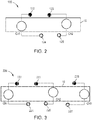
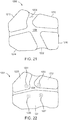
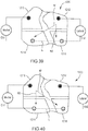
- the current flowing via a first channel Ch1 of the electric circuit is transmitted to at least a first electrode 122 of the electrode assembly 120, through one or more nerves and/or muscles of the limb 10, and at least a portion of the current is returned through at least a second electrode 124 of the electrode assembly 120 to the electric stimulator 140.
- the first channel Ch1 of stimulation includes the first electrode 122 and the second electrode 124, as shown in FIG. 2 .
- the current flowing via a second channel Ch2 of the electric circuit is transmitted to at least a third electrode 123 of the electrode assembly 120, through one or more nerves and/or muscles of the limb 10, and at least a portion of the current is returned through a fourth electrode 125 of the electrode assembly 120 to the electric stimulator 140. In some embodiments, however, at least a portion of the current flowing in the second channel can be returned through the second electrode 124.
- the second channel Ch2 of stimulation includes the third electrode 123 and the fourth electrode 125, and/or, in some embodiments, the second electrode 124.
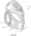
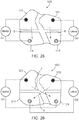
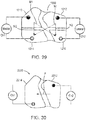
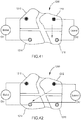
- the electric stimulator 140 is configured to transmit an electrical current along a third portion or channel of an electric circuit, which is electrically coupled to the electrode assembly.
- electrical current is provided in a first channel Ch1 between a first electrode 222 of an electrode assembly 220 (which can be similar in many respects to electrode assembly 120) and a second electrode 224 of the electrode assembly, through one or more nerves or muscles of the limb 10, in a second channel Ch2 between a third electrode 223 and fourth electrode 225 of the electrode assembly 120, through one or more nerves or muscles of the limb 10, and via a third channel Ch3 between a fifth electrode 226 and a sixth electrode 227, through one or more nerves or muscles of the limb 10.
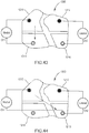
- electrodes 224, 225 and 227 are shown and described above as returning a current from electrodes 222, 223 and 226, respectively, and thus forming a portion of the first, second and third stimulation channels, respectively, in some embodiments, one or more of electrodes 224, 225, and 227 can be selectively configured to return at least a portion of the current flowing from a different one or an additional one of electrodes 222, 223, 226. In this manner, for example, electrode 224 can selectively form a portion of the second channel Ch2 and/or the third channel Ch3 in addition to and/or instead of the first channel Ch1.
- electrode 225 can selectively form a portion of the first channel Ch1 and/or the third channel Ch3 in addition to or instead of the second channel Ch2.
- electrode 227 can selectively form a portion of the first channel Ch1 and/or the second channel Ch2 in addition to or instead of the third channel Ch3.
- the current flowing via each of the first and second (and, optionally, third) channels provides FES to one or more nerves or muscles of the limb, such as the peroneal nerve of the leg thereby resulting in dorsiflexion and/or plantarflexion of the foot as well as a neutral foot (or at least reduced inversion or eversion of the foot) substantially at the time of the heel-off event (e.g., a very short time after the sensor 130 detects the heel-off event consistent with a rate of electrical signal and/or electrical current transmission such as, 0.10 seconds, 0.05 seconds, 0.01 seconds, 0.001 seconds, 0.0001 seconds, or less).
- electrical current flowing via the first channel has a first intensity and electrical current flowing via the second channel has a second intensity, which can promote a balanced or neutral foot position in conjunction with the foot's dorsiflexion (also referred to herein as "balanced dorsiflexion").
- multiple-channel (e.g., dual-channel or triple-channel) FES is configured to reduce the degree of or eliminate eversion or inversion of the foot that may otherwise occur in the presence of dorsiflexion or plantarflexion of the foot resulting from single-channel FES. As a result, the foot of the patient flexes toward the leg and moves towards a neutral position, enhancing a portion of the patient's gait.
- the senor 130 can sense and/or detect a characteristic associated with a second gait event such as, for example, a "heel-on” event (i.e., the point during gait at which the heel is placed in contact with the surface of upon which the patient is walking). As described above, the sensor 130 can send a signal associated with the characteristic to the electric stimulator 140 and, upon receipt, the electric stimulator 140 can terminate the flow of electrical current to the electrodes.
- a characteristic associated with a second gait event such as, for example, a "heel-on” event (i.e., the point during gait at which the heel is placed in contact with the surface of upon which the patient is walking).
- a “heel-on” event i.e., the point during gait at which the heel is placed in contact with the surface of upon which the patient is walking.
- the electric stimulator 140 can send an electrical current along an electric circuit, such as via at least two of the first channel, the second channel, or an optional third channel of the electrical circuit, that is electrically coupled to one or more electrodes in electrical communication with one or more target nerves or muscles of the leg (e.g., the tibial nerve).
- the electrodes can provide FES to the tibial nerve resulting in a balanced or neutral foot position in conjunction with the foot's plantarflexion (referred to herein as "balanced plantarflexion") substantially at the time of the heel-on event (as described above).
- the termination of the FES to a first target nerve relaxes the portion of the neuromuscular system resulting in a relaxation of the dorsiflexion
- the FES provided to a second target nerve results in plantarflexion of the foot
- the FES is provided to at least another nerve and/or muscle of the leg to reduce and/or eliminate eversion or inversion of the foot.
- the foot flexes away from the leg and the foot is in or moves toward a neutral position, thereby enhancing a portion of the patient's gait.
- the electric stimulator 140 can include a microprocessor, such as, for example, an application-specific integrated circuit (ASIC) or a combination of ASICs, which are designed to perform one or more specific functions.
- the stimulator 140 can include an analog or digital circuit, or a combination of multiple circuits.
- the stimulator 140 can include a memory, such as, for example, a read only memory (ROM) component, a random access memory (RAM) component, electronically programmable read only memory (EPROM), erasable electronically programmable read only memory (EEPROM), and/or flash memory.
- the electric stimulator 140 can include, for example, a memory or the like that can be configured to store information at least partially defining a set of parameters associated with the FES.
- the electric stimulator 140 can be configured to store information associated with an amplitude, voltage, pulse rate, waveform, and/or current level associated with the FES, a sensitivity associated with the sensor 130, a repository of actions to perform based on information received from the sensor 130, and/or any other suitable information and/or logic.
- the electric stimulator 140 can be configured to provide FES to the impaired leg with a set of characteristics that can be uniquely associated with the patient.
- the electric stimulator 140 is configured to store data, including, but not limited to, usage data (e.g., historical data associated with the FES provided to the patient via the orthosis 105, including the set(s) of parameters associated with the FES, the frequency of use, the duration of use over a time period, e.g., on a daily, weekly and/or monthly basis), data associated with the patient's gait (e.g., multiple individual parameters associated with the patient's gait), data associated with the patient's number of daily steps taken, data associated with a distance traveled by the patient during gait or other physical activity (e.g., cycling, rowing, paddling, or the like), data associated with the patient's daily range of motion for the impaired limb, data indicative of the frame assembly or assemblies to which the electric stimulator has been coupled to (or attempted to be coupled to) and the duration of such coupling, or the like.
- usage data e.g., historical data associated with the FES provided to the patient via the orthosis 105, including the set
- the patient and/or a health care professional can manipulate the electric stimulator 140 to change one or more parameters and/or characteristics associated with the FES provided to the impaired leg.
- a health care professional can adjust (e.g., increase or decrease) the intensity of electrical current flowing via the first channel of the stimulator 140 and can adjust the intensity of electrical current flowing via the second channel of the stimulator 140 until a neutral foot position is achieved (e.g., the foot is in a neutral position or inversion or eversion of the foot is reduced), and the intensity for each channel resulting in the desired foot position can be stored as a parameter associated with the FES.
- the health care professional can adjust the amplitude of the electrical current flowing via each of the first and second channels of the stimulator 140 until a neutral or balanced foot position and/or dorsiflexion is achieved, and the amplitude for each channel resulting in the desired foot position can be stored in the stimulator 140 as a parameter associated with the FES.
- Such adjustment of the one or more parameters can be performed, for example, by a healthcare professional during an initial session to set up the orthosis 105 with the patient, or during one or more other sessions, check-ups, or the like. Additionally such adjustment of the one or more parameters can be performed, in one embodiment, directly via a user interface of the electric stimulator 140 (e.g., accessible on or through the housing of the electric stimulator).
- such adjustment can be performed via a control device distinct from the electric stimulator 140, as described in more detail herein with respect to control devices 3500, 3550.
- the electric stimulator 140 is configured for wireless communication with the control device, as also described in more detail herein. More specifically, the electric stimulator 140 can be configured to receive a wireless signal from the control device, to send a wireless signal to the control device, or both. In this manner, for example, the electric stimulator 140 can be controlled via wireless signal(s) by the control device, and can wirelessly transmit to the control device data stored in the electric stimulator 140 (e.g., usage data or the like).
- At least one of the stimulator 140 (e.g., via the microprocessor or other suitable component therein) or the control device is configured to change one or more parameters and/or characteristics associated with the FES provided to the impaired leg.
- the stimulator 140 (and/or control device) is configured to receive one or more signals associated with the patient's gait from one or more sensors 130.
- the stimulator 140 (and/or control device) can be configured to process such signal(s) in a manner to measure, calculate or the like a different parameter associated with the patient's gait.
- the stimulator 140 (and/or control device) can be configured to change one or more parameters and/or characteristics associated with the FES provided to the impaired leg based on the measured or calculated parameter.
- the stimulator 140 is configured to receive from a gyroscope at a first time a signal associated with a first gait parameter (e.g., a first angle of a portion of the leg during a gait event, such as during a step or swing phase) and to receive from the gyroscope at a second time subsequent the first time a second signal associated with a second gait parameter (e.g., a second angle of the portion of the leg during the gait event or a subsequent gait event).
- a first gait parameter e.g., a first angle of a portion of the leg during a gait event, such as during a step or swing phase
- a second signal associated with a second gait parameter e.g., a second angle of the portion of the leg during the gait event or a subsequent gait event.
- the first and second signals received by the stimulator 140 from the gyroscope are indicative of a range of motion of the limb.
- the stimulator 140 can be configured to measure or calculate (e.g., via execution of a set of stored instructions) a distance traveled on the first signal and the second signal. Said another way, the stimulator 140 can be configured to measure or calculate a distance traveled based on the range of motion measurements associated with the limb. In some embodiments, the stimulator 140 is configured to adjust one or more parameters associated with the FES based on the measured or calculated range of motion.
- the stimulator 140 is configured to send to the control device a signal associated with the first and second signals received from the gyroscope, and the control device is configured to calculate the distance traveled (or other gait parameter).
- the control device can be configured to send to the stimulator 140 a signal that includes instructions to adjust one or more parameters and/or characteristics associated with the FES based on the calculated distance traveled.
- the control device can be configured to send to the stimulator 140 a signal associated with the calculated distance traveled, and the stimulator can be configured to adjust, based on the received signal, one or more parameters and/or characteristics associated with the FES.
- At least one of the stimulator 140 (e.g., via the microprocessor or other suitable component therein) or the control device is configured to change one or more parameters and/or characteristics associated with the FES provided to the impaired leg based at least in part on motion capture technology.
- the FES system includes motion capture technology configured to image a portion of the limb (e.g., the patient's foot) during at least a portion of the gait cycle.
- the stimulator 140 (or the control device 160) can be configured to adapt one or more stimulation parameters based on the image, and more particularly, with one or more data points associated with the image, and optionally also based on one or more signals associated with the patient's gait received from one or more sensors 130.
- the system can be configured to image the patient's foot during gait, and depending on whether data derived from the image indicated inversion or eversion of the foot, the stimulator 140 (or the control device 160) can adaptively adjust one or more stimulation parameters based on the data from the image, and optionally also based on one or more sensors received from one or more sensors 130.)
- the electric stimulator 140 is configured for use with more than one orthosis (for example, as described in more detail with respect to FIG. 66 ).
- the electric stimulator 140 can be configured for use with the FES orthosis 105, which can be an orthosis configured to be donned on the right leg of the user, and configured for use with a FES orthosis (not shown in FIG. 1 ) configured to be donned on the left leg of the user.
- the FES orthosis 105 can be an orthosis configured to be donned on the right leg of the user, and configured for use with a FES orthosis (not shown in FIG. 1 ) configured to be donned on the left leg of the user.
- Such an orthosis can be identical in function to the FES orthosis 105, however, components of the orthosis can be arranged in a substantially mirror image to facilitate placement on the opposing leg, and thus are not described in detail herein.
- the electric stimulator 140 can be configured for use with an orthosis configured to be disposed on a different limb or limb segment of the patient's body, such as the patient's upper leg or thigh, or the patient's arm.
- the electric stimulator 140 can be configured for use with an orthosis 505, shown and described herein with respect to FIG. 47 .
- the electric stimulator 140 can be configured to store information associated with each FES orthosis (e.g., in the stimulator's memory), including one or more stimulation parameters associated with each FES orthosis.
- the electric stimulator 140 includes a sensor or other mechanism configured to detect to which orthosis the stimulator is coupled.
- the orthosis 105 includes an identification mechanism configured to be detected and/or read by the stimulator 140 and by which the stimulator can determine to which orthosis the stimulator is coupled. In this manner, the electric stimulator 140 can be configured to select a stimulation program, or the like, based on the detected orthosis.
- the stimulator 140 is configured to determine whether it is programmed for use with an orthosis.
- the stimulator 140 can be configured to prevent initiating an electrical current or stimulation signal if the stimulator 140 determines that it is not programmed for use with the orthosis.
- the stimulator 140 can be configured to provide an indicium that it has determined that it is not programmed for use with the orthosis.
- the indicium can be, for example, audible (e.g., a beep, alarm or other audible signal), visual (e.g., a displayed message, light, symbol, or the like), or tactile (e.g., a vibration or the like), or any combination of the foregoing.
- the electric stimulator 140 is configured to be in electrical communication with an electric stimulator of another orthosis, as also described herein with respect to FIG. 66 .
- the electric stimulator 140 can be in communication with a control device 160.
- the control device 160 can be any suitable electronic device that can provide an interface for a user (e.g., the patient and/or a health care professional) to manipulate one or more characteristics and/or parameters associated with the FES.
- the control device 160 can be, for example, a personal computer (PC), a personal digital assistant (PDA), a smart phone, a laptop, a tablet PC, a server device, a workstation, and/or the like.
- the electronic device can include at least a memory (e.g., a random access memory (RAM), a memory buffer, a hard drive, a read-only memory (ROM), an erasable programmable read-only memory (EPROM), and/or the like); a processor (e.g., a general purpose processor, a central processing unit (CPU), an accelerated processing unit (APU), and Application Specific Integrated Circuit (ASIC), and/or the like); a network interface (e.g., a network interface card and/or the like that can include at least an Ethernet port and/or a wireless radio (e.g., a WiFi® radio, a Bluetooth® radio, etc.)); and an output device (e.g., a display such as a cathode ray tube (CRT) monitor, a liquid crystal display (LCD) monitor, a light emitting diode (LED) monitor, and/or the like, a Universal Serial Bus (USB) drive, an ANT+ compatible device or application, and/or
- control device 160 can be in communication with the electric stimulator 140 via the network interface and the processor can be configured to run or execute a set of instructions or code stored in the memory associated with using, for example, a PC application, a mobile application, an internet web browser, a cellular and/or wireless communication (via a network), and/or the like to communicate with and/or otherwise control at least a portion of the electric stimulator 140, as described herein with respect to specific embodiments.
- the electric stimulator 140 can be devoid of a user interface, such as a user interface accessible via an outer surface of a housing of the stimulator, thereby reducing manufacturing costs for the stimulator, simplifying usage of the FES system 100, and also reducing potential damage to the electrical circuit that may occur in the event of moisture ingress via such a user interface.
- a user interface such as a user interface accessible via an outer surface of a housing of the stimulator
- FIGS. 4-22 are illustrations of portions of a system 1000 used, for example, in gait modulation according to an embodiment.
- the system 1000 can be used by a human patient who has one or more impaired limbs as a result of injury and/or disease (e.g., stroke, spinal cord injury, head injury, cerebral palsy, multiple sclerosis, etc.).
- the system 100 includes a functional electrical stimulation (FES) orthosis 1050 (also referred to herein as "orthosis" and/or “device”) that is placed in physical and electrical contact with, for example, a lower limb segment of an impaired leg (not shown in these figures).
- FES functional electrical stimulation
- At least a portion of the orthosis 1050 can be substantially similar in form and/or function to those described in the '556 patent, the '036 patent, the '110 patent, and/or the '340 application incorporated by reference in their entireties above, or any other orthosis shown and/or described herein (e.g., orthosis 105).
- the patient and/or a health care professional can engage the system 1000 in such a manner as to cause the orthosis 1050 to selectively provide functional electrical stimulation to a portion of a neuromuscular system of the leg, which can, in turn, facilitate gait of the patient who might otherwise experience, for example, drop foot or the like, as described in further detail herein.
- the orthosis 1050 includes a frame assembly 1100, an electrode assembly 1200, and an electric stimulator 1400. Although not shown in FIGS. 4-22 , the orthosis 1050 can also include and/or otherwise be operably coupled to one or more sensors shown and described herein.
- the frame assembly 1100 is configured to be removably coupled to a portion of a limb such that the portion of the limb is substantially enveloped by the frame assembly.
- the frame assembly 1100 of the orthosis 1050 can have any suitable shape and/or size that can be, for example, associated with a segment of the leg and includes at least a portion that can be transitioned between a first (or open) configuration and a second (or closed) configuration to couple the frame assembly 1100 to the leg.
- the frame assembly 1100 can have a shape and size that are associated with a portion of the lower leg (e.g., between the knee and the foot of the lower leg).
- an upper portion 1105 of the frame assembly 1100 can form an ergonomic contour (e.g., a locator portion 1106) that can, for example, substantially correspond with a shape of an inferior border of a patella of a knee of the leg.
- a lower portion 1115 of the frame assembly 1100 can form an ergonomic contour (e.g., a locator portion 1117) that can, for example, substantially correspond with a shape of the tibial crest.
- the frame assembly 1100 can define an ergonomic cross-sectional shape taken about a plane that is normal to a longitudinal axis of the frame assembly 1100 (e.g., substantially coaxial with an axis defined by the segment of the leg) that corresponds to and/or otherwise is associated with a shape of a tibial crest of the lower leg.
- the orthosis 1105 optionally includes a visual locator 1104 that is configured to be aligned with a predetermined portion of the patient's anatomy (e.g., a center of the knee, the tibial crest, or the like).
- the frame assembly 1100 can be substantially similar in form and/or function as those described in the '556 patent, the '036 patent, the '110 patent, and/or the '340 application, incorporated by reference above, or any frame assembly described herein (e.g., frame assembly 110).
- the frame assembly 1100 includes a frame 1110 (also referred to herein as a "first layer” or “inner structure”), a cradle 1130, a coupling portion 1140, an inner layer 1160 (also referred to herein as a “second layer”), and an outer layer 1170 (also referred to herein as a "third layer” or “cover”).
- a portion of the frame assembly 1100, such as the frame 1110 can be formed from a semi-rigid material such as, for example, a relatively thin metal, a thermoplastic, a polymer, and/or the like.
- the frame 1110 can be sufficiently rigid to provide structural support for the orthosis 1050, while being sufficiently flexible to allow the limb about which the frame 1110 is disposed to increase or decrease during, for example, muscle flexion or muscle relaxation, respectively.
- the frame 1110 can be substantially C-shaped such as to allow the frame 1110 to expand and contract in response to the expansion and contraction of the leg, respectively.
- the arrangement of the frame 1110 can be such that when the size of the leg is reduced (e.g., after expansion due to muscle flexion), the rigidity of the frame 1110 can be sufficient to transition the frame 1110 to a size and shape associated with the reduced size of the leg.
- the frame 1110 can be biased such that when an external force that expands the frame 1110 to an expanded size is removed, the frame 1110 returns to an unexpanded size, smaller than the expanded size.
- the frame 1110 can include one or more spring members (not shown) coupled to the frame 1110 and configured to bias opposing ends of the frame 1110 towards each other, as indicated by arrows A and B in FIG. 10 , thus reducing a cross-sectional area defined within the C-shaped of the frame 1110.
- a first spring member can be coupled to the frame 1110 at one or more upper spring connectors 1113 formed on an upper portion of the frame 1110
- a second spring member can be coupled to the frame 1110 at one or more lower spring connectors 1112, 1114 formed on a lower portion of the frame 1110.
- reference to "upper” and “lower” in this section refer to respective positions when the frame assembly 1100 is donned on the leg of a standing patient. In the absence of such spring members, in use, the opposing ends of the frame 11 10 can tend to move away from each other, as indicated by arrows C1 and C2 in FIG. 11 .
- the frame 1110 can be constructed of an inner portion 1116 and an outer portion 1118.
- the inner portion 1116 can be formed, and then the outer portion 1118 of the frame 1110 can be over-molded or otherwise coupled to the inner portion of the frame 1110.
- the inner portion 1116 of the frame 1110 includes a plurality of retaining members 1120, 1122, 1124, 1126, each of which is inwardly biased towards the interior volume defined by the C-shaped frame 1110.
- the inner portion 1116 is shown and described as included four retaining members 1120, 1122, 1124, 1126, in other embodiments, any suitable number of retaining members may be included in the inner portion of the frame (e.g., one, two, three, five, or more).
- this arrangement enables the frame assembly 1100 to substantially envelop the portion of the leg, and serves to effectively disperse a pressure and/or strain that would otherwise be exerted on the portion of the leg, thereby retaining the natural profile and geometry of the leg tissue and/or muscles when coupled thereto.
- at least a portion of the frame 1110 such as one or more portions of the inner portion 1116 of the frame, can define a plurality of openings 1128 configured to allow airflow through the frame, as shown in FIG. 10 , and thus enhance patient comfort.
- the frame 1110 can be substantially similar in form and/or function as a central frame or inner structure described in the '556 patent, the '036 patent, the '110 patent, and/or the '340 application, incorporated by reference above.
- the inner layer 1160 (see, e.g., FIGS. 6 and 15 ) of the frame assembly 1100 is configured to substantially cover an inner surface of the frame 1110.
- the inner layer 1160 can be formed from any suitable material and/or combination of materials.
- the inner layer 1160 can be formed from a relatively flexible and/or soft material that can elastically deform when exposed to an external force.
- At least a portion of the inner layer 1160 can be formed from a brushed fabric, a hook and/or loop material, or the like, such as those offered commercially by Nam Liong Enterprise Co., Ltd. In this manner, the inner layer 1160 can be configured to help retain the electrode assembly 1200 to the frame assembly 1100.
- the inner layer 1160 can include a hook and/or loop material configured to engage with and couple to a complementary material (e.g., the other of the hook and/or loop material) on an electrode base (not shown). Also in this manner, the inner layer 1160 can enhance the ergonomics (e.g., comfort) of the frame assembly 1100 by forming a relatively flexible and/or soft layer that is placed in contact with the patient.
- at least a portion of the inner layer 1160 such as a portion of the inner layer 1160 defining openings 1162, 1164, 1166, 1168, is formed of a polypropylene material.
- the outer layer 1170 of the frame assembly 1100 can be configured to be disposed on an outer surface of the frame 1110. Referring to FIG. 16 , the outer layer 1170 defines an opening 1172 (shown in dashed lines in FIG. 16 ) configured to be disposed about at least a portion of the cradle 1130.
- the outer layer 1170 can be formed from any suitable material and/or combination of materials. In some embodiments, the outer layer 1170 can be formed from a relatively flexible and/or soft material that can elastically deform when exposed to an external force. For example, the outer layer 1170 can be formed, at least in part, from elastane or spandex (such as Lycra®) or any other suitable material.
- the outer layer 1170 can enhance the ergonomics (e.g., comfort) of the frame assembly 1100 by forming a relatively flexible and/or soft layer that may contact with the patient.
- the outer layer 1170 includes a membrane 1174 extended from an inner surface of the outer layer 1170 and configured to be inserted between portions of the frame 1110 such that the membrane 1174 is disposed on an inner surface of a base plate 1 134 of the frame 1110.
- the membrane 1174 can be configured, for example, to help limit the ingress of moisture (e.g., water, sweat, or the like) into the frame assembly 1100 that may enter through an opening of the cradle 1130.
- the inner layer 1160 and the outer layer 1170 can be coupled to the frame in any suitable manner. In some embodiments, for example, at least one of the inner layer 1160 and the outer layer 1170 is welded to the frame 1110. As shown in FIG. 17A , the inner layer 1160 and outer layer 1170 can each abut a shoulder portion 1107, 1109, respectively, formed by an edge of the frame 1110 and be welded at regions 1161, 1171, respectively, to the frame 1110. As also shown in FIG. 17A , in some embodiments, the frame assembly 1100 includes a layer of padding 1108 disposed between at least a portion of the outer layer 1170 and the frame 1110. In some embodiments, such padding 1108 can be integrally formed with the outer layer 1170.
- an edge of the frame 1110 defines an inner channel 1107' and an outer channel 1109'. Edges 1161', 1171' of the inner layer 1160 and the outer layer 1170, respectively, are disposed in the channels 1107', 1109', respectively, and are welded to the frame 1110.
- at least one of the inner layer 1160 and the outer layer 1170 can be, for example, over-molded about portions of the frame 1110.
- at least one of the inner layer 1160 and the outer layer 1170 can be removably disposed about or coupled to the frame 1110.
- the frame assembly 1100 includes a removable layer or panel 1180 that is removably coupleable to an inner surface (e.g., the inner layer 1160) of the frame assembly.
- the panel 1180 can, for example, provide a hygienic barrier between the frame assembly 1100 and the patient's body during use, thus facilitating the frame assembly 1100 to be shared between or used on multiple patients or users in a more sanitary manner.
- the removable panel 1180 includes a first side 1182, at least a portion of which is configured to be in contact with at least a portion of an inner surface (e.g., the inner layer 1160) of the frame assembly 1100.
- the panel 1180 includes a second side 1184, opposite the first side 1182, at least a portion of which is configured to be in contact with the limb segment.
- the panel 1180 can be removably coupled to the frame assembly 1100 in any suitable manner, including, but not limited to, a hook and loop fastener, a clip, a snap connector, a magnet, a protrusion and receiving sleeve or recess combination, or any other suitable fastening mechanism, or combination thereof.
- the first side 1182 of the removable panel 1180 includes at least a portion of a hook and loop fastener configured to removably couple to a complementary portion of the hook and loop fastener disposed on an inner surface (e.g., the inner layer 1160) of the frame assembly 1100.
- the first side 1182 of the removable panel 1180 includes a strap 1183 (see, e.g., FIG. 18B ) connected at each end to the panel 1180 and that is configured to receive therethrough a portion of frame assembly 1100 (e.g., of the inner layer 1160) to removably couple the panel 1180 to the frame assembly 1100.
- the removable panel 1180 can have a perimeter profile that is substantially similar to the perimeter profile of the inner surface (e.g., the inner layer 1160) of the frame assembly 1100, including, for example, contoured portions corresponding to the locator portions of the frame assembly. In this manner, the panel 1180 can substantially prevent direct contact between the inner layer 1160 of the frame assembly 1100 and the limb segment during use. Also in this manner, in some embodiments, substantially no portion of the panel 1180 extends beyond the perimeter profile of the frame assembly 1100 (e.g., of the inner layer 1160 of the frame assembly).
- the removable panel 1180 defines a set of connector openings 1186 through which at least a portion of the electrode assembly 1200 can be disposed.
- one or more wires 1240, 1242, 1244, 1246 of the electrode assembly 1200 can each be disposed through a respective opening of the set of connector openings 1186 to electrically couple the electrode assembly 1200 to the electric stimulator 1400.
- the set of openings 1186 can include one, two, three, four (as shown in FIGS. 18A-18B ), five, six, or more connector openings.
- the openings 1186 are shown as being substantially circular in shape, in other embodiments, the openings can be any suitable shape or dimension.
- a polypropylene layer 1187 is circumferentially disposed about one or more openings of the set of openings 1186 on the first side 1182 of the panel 1180.
- the polypropylene layer 1187 is shown and described as circumscribing an entirety of the circumference of the opening 1186, in some embodiments, the polypropylene layer is circumferentially disposed about a portion of the opening.
- the polypropylene layer 1187 or a layer of another suitable material is disposed around each opening in the set of openings 1186, or only a portion of the openings in the set of openings.
- a fastener 1188 (or portion thereof) is circumferentially disposed about one or more openings of the set of openings 1186 on the second side 1184 of the panel 1180.
- a hook and loop fastener e.g., such as that commercially marketed as Velcro®
- the fastener 1188 is shown and described as circumscribing an entirety of the circumference of the opening 1186, in some embodiments, the fastener is circumferentially disposed about a portion of the opening 1186. In this manner, the fastener is configured to couple at least a portion of the electrode assembly 1200 (e.g., an electrode base of the electrode assembly) to the panel 1180, and thus to the frame assembly 1100.
- the cradle 1130 of the frame assembly 1100 is disposed on the frame 1110 to define a receiving portion 1132 (see, e.g., FIG. 14 ) on or within which the electric stimulator 1400 (e.g., a housing of the electric stimulator) can be at least partially disposed.
- the base plate 1134 (see, e.g., FIG. 13 ) defined by the frame 1110 can be coupled to, and provide support for, the cradle 1130 coupled thereto.
- the base plate 1134 can include openings 1136, 1137 through which the electrodes can be coupled to the stimulator 1400 (e.g., via one or more wires or connectors).
- the cradle 1130 includes a rear wall 1135 and one or more walls 1138 extended from the rear wall (e.g., from a perimeter or portion thereof of the rear wall).
- the receiving portion 1132 is defined by the rear wall 1135 and the one or more walls 1138 extended from the rear wall.
- at least one wall 1138 can define a cut-out or recess 1139 configured to facilitate gripping of the stimulator 1400 by the user, for example, during removal of the stimulator 1400 from the cradle 1130.
- the wall 1138 defines a recess 1139 at opposing ends (e.g., the top and bottom) of the cradle 1130, however, in other embodiments, the wall can define a single recess (e.g., disposed at a top, bottom, or side of the cradle) or two or more recesses at different locations of the wall (e.g., at opposing side portions of the wall extending between the top and bottom of the cradle).
- the cradle 1130 can include any suitable surface finish, protrusion, detent, etc. that can act to at least temporarily retain the electric stimulator 1 400 within or with respect to the set of walls forming the cradle 1130.
- the cradle 1130 can form and/or define a set of detents that can matingly receive a set of corresponding protrusions extending from an outer surface of the electric stimulator 1400 when therein (or vice versa).
- the stimulator can be coupled to and retained by the cradle using single or multiple snap-fit connectors.
- an inner surface of the cradle 1130 can have a finish and/or can be formed from a material with a relatively high coefficient of friction.
- an outer surface of the electric stimulator 1400 and an inner surface of the cradle 1130 can form and/or define a friction fit that can at least temporarily retain the electric stimulator 1400 in the cradle 1130.
- the cradle 1130 includes and/or forms a set of connectors 1131 via which the orthosis 1050, and more specifically connectors (not shown) of the electrode assembly 1200 (or a connection assembly), can be electrically coupled to corresponding connectors (not shown) of the electric stimulator 1400. Therefore, when the electric stimulator 1400 is positioned on the cradle 1130, the electric stimulator 1400 is placed in electrical communication with the electrode assembly 1200, as described in further detail herein.
- the coupling portion 1140 of the frame assembly 1100 can be transitioned between a first (e.g., open) configuration and a second (e.g., closed) configuration (e.g., as shown in FIG. 6 ) to reversibly couple the frame assembly 1100 to the leg.
- a first (e.g., open) configuration e.g., open) configuration
- a second (e.g., closed) configuration e.g., as shown in FIG. 6
- the frame assembly 1100 can be positioned about a portion of the leg and the coupling portion 1140 can be transitioned to the second configuration to removably couple (i.e., at least temporarily couple) the frame assembly 1100 to the leg.
- the coupling portion 1140 includes substantially parallel, modular straps 1142, 1144 (e.g., elastic straps, inelastic straps, and/or straps including one or more elastic portions and one or more inelastic portions) connecting between the frame assembly 1100 and a handle 1150.
- the handle 150 is coupled at an end portion of each strap 1142, 1144 (see, e.g., FIG. 6 ), and an opposing end of each strap 1142, 1144, respectively, is coupled to the frame assembly 1100 (see, e.g., FIGS. 4 and 5 ).
- the arrangement of the coupling portion 1140 is such that during donning, the straps 1142, 1144 wrap circumferentially around a portion of the limb segment (e.g., the leg), to securely couple the orthosis 1050 to the limb segment.
- the handle 1150 can form and/or provide a structure that can facilitate the engagement of the coupling portion 1140.
- the handle 1150 can define an opening shaped to be disposed about the stimulator 1400 (e.g., the housing of the stimulator), when the stimulator is coupled to the frame assembly 1100, as shown in FIGS. 5 and 6 , and/or disposed about a portion of the cradle 1130, as shown in FIG. 14 .
- the handle can facilitate the engagement and/or manipulation of the coupling portion 1140 by a patient who may have impairment in one or both hands.
- a portion 1152 of the handle can be contoured (e.g., between a top portion of the handle and a bottom portion of the handle) such that an opening 1154 is defined between the handle 1150 and the cradle 1130 when the handle 1150 is coupled about the cradle 1130.
- the opening 1154 is configured to facilitate gripping of the handle 1150 (e.g., by a finger of the user) during coupling and or decoupling of the handle 1150 from about the cradle 1130 and/or the stimulator 1400.
- the frame assembly 1100 includes electrode connectors configured to engage a portion of the electrode assembly 1200.
- the electrode connectors are configured to mechanically couple one or more electrodes to the frame assembly 1100, and to electrically couple one or more electrodes to the electric stimulator 1400, as described herein.
- the frame assembly 1100 includes four electrode connectors 1230, 1232, 1234, 1236. As described herein, in some embodiments, two electrodes 1230, 1234 are associated with a first stimulation channel, and two electrodes 1232, 1236 are associated with a second stimulation channel.
- Each electrode connector 1230, 1232, 1234, 1236 is coupled to, and optionally at least partially disposed within or extended through, an opening 1162, 1164, 1166, 1168, respectively, of the inner layer 1160 of the frame assembly 1100, such that the electrode connectors 1230, 1232, 1234, 1236 are accessible via an inner surface of the frame assembly 1100.
- the openings 1162, 1164, 1166, 1168 of the inner layer 1160 correspond to openings 1121, 1123, 1125, 1127 defined by the frame 1110 (see, e.g., FIG.
- the electrode connectors 1230, 1232, 1234, 1236 can be disposed within or extended through the openings 1121, 1123, 1125, 1127 defined by the frame 1110.
- At least one electrode connector 1230, 1232, 1234, 1236 is configured to be unused (e.g., not coupled to an electrode) when the electrode assembly 1200 is coupled to the frame assembly 1100.
- the unused electrode connector(s) 1230, 1232, 1234, 1236 can optionally have one or more connector covers disposed thereon to prevent the inadvertent flow of electrical current therefrom during FES.
- a connector cover 1270 according to an embodiment is configured to be removably coupled to an unused electrode connector (e.g., electrode connectors 1230, 1232, 1234, 1236).
- the connector cover 1270 includes an outer layer 1272, an inner layer 1274, an outer snap portion 1276, and an inner snap portion 1278. At least one of the outer layer 1272 of the cover 1270 and the inner layer 1274 of the cover 1270 is formed from a non-conductive material. At least one of the outer layer 1272 of the cover 1270 and the inner layer 1274 of the cover 1270 has a sufficient size and shape to wholly cover at least one of the openings 1162, 1164, 1166, 1168 of the inner layer 1160 of the frame assembly 1100.
- the outer snap portion 1276 is at least partially disposed between the outer and inner layers 1272, 1274 and includes a protrusion that extends through an opening 1275 of the inner layer 1274.
- the outer snap portion 1276 is configured to matingly engage the inner snap portion.
- the inner snap portion 1278 is configured to snap-fit with at least one of the electrode connectors (e.g., electrode connectors 1230, 1232, 1234, 1236).
- the connector cover 1270 is coupled to an unused connector to prevent the inadvertent flow of electrical current from the unused connector during FES.
- the connector cover can be differently configured (e.g., to include a single non-conductive layer) and/or be configured to couple to the frame assembly 1100 and/or one or more of the electrode connectors 1230, 1232, 1234, 1236 in a different manner.
- wires 1240, 1242, 1244, 1246 substantially extend between the electrode connectors 1230, 1232, 1234, 1236, respectively, and the electric stimulator 1400 (or one or more connectors of the frame assembly 1100 configured to be electrically coupled to the electric stimulator, such as via the openings 1136, 1137 of the base plate 1134 of the inner portion 1116 of the frame and/or via the set of connectors 1131 of the cradle 1130) and are configured to electrically couple the electric stimulator 1400 to the electrode assembly 1200.
- wires 1240, 1244 can be configured to electrically couple two electrode connectors 1230, 1234 to the electric stimulator 1400 via a first connector (not shown, e.g., through one of the cradle connector openings), thereby forming at least a portion of a first electrical stimulation channel
- wires 1242, 1246 can be configured to electrically couple the other two electrode connectors 1232, 1236 to the electric stimulator 1400 via a second connector (not shown, e.g., through the other of the cradle connector openings), thereby forming at least a portion of a second electrical stimulation channel.
- This arrangement facilitates dual-channel functional electrical stimulation by the system 1000, as described in further detail herein.
- the electrode connectors 1230, 1232, 1234, 1236 can be any suitable shape, size, or configuration. As shown, the electrode connectors 1230, 1232, 1234, 1236 are in the form of snap connectors. In other embodiments, the electrode connectors can form a button, a detent, a protrusion, one half of a hook-and-loop coupler (i.e., Velcro®), and/or the like. As such, the electrode connectors 1230, 1232, 1234, 1236 can each be matingly placed in contact with a corresponding portion of an electrode included in the electrode assembly 1200 to at least temporarily retain the electrodes in a substantially fixed position relative to the frame assembly 1100.
- Velcro® hook-and-loop coupler
- the position of the electrode connectors 1230, 1232, 1234, 1236, and hence the electrodes coupled thereto can be associated with a target portion of the neuromuscular system of the leg such as, for example, the peroneal nerve and/or the tibial nerve.
- a target portion of the neuromuscular system of the leg such as, for example, the peroneal nerve and/or the tibial nerve.
- the first and second connectors of the frame assembly 1100 and corresponding connectors of the electrode assembly 1200 electrically couple the electric stimulator 1400 to the electrodes 221 such that at least two channels of electrical current can flow from the electric stimulator 1400 and through the electrodes 221 to provide functional electrical stimulation to the portion of the neuromuscular system of the leg, as described in further detail herein.
- the frame assembly 1100 is shown and described herein as including an at least semi-rigid frame 1110, in other embodiments, the frame assembly 1100 can be devoid of such a frame 1110.
- the frame assembly 1100 can include only the inner layer 1160, only the outer layer 1170, only the inner layer 1160 and the outer layer 1170, or any combination of the inner layer 1160, outer layer 1170 and/or a different soft and/or flexible layer or cuff.
- the cradle 1130 can be coupled to and/or supported at least in part by the inner layer 1160, the outer layer 1170, the different soft and/or flexible layer or cuff, or any combination of the foregoing.
- the electric stimulator 1400 is not supported by the frame assembly 1100 of the orthosis 1050, as described herein, but rather can be electronically (and, optionally, mechanically) coupled to the electrodes of the orthosis 1050 by only a cable or wire, or any suitable electrical (and/or mechanical) connection.
- the electrode assembly 1200 is removably coupled to the frame assembly 1100.
- the electrode assembly 1200 can include electrodes in any suitable configuration, and can be substantially similar in form and function to electrode assembly 120 described herein.
- Each electrode can be engaged by the system 1000, and the electric stimulator 1400 particularly, to promote desired movement of the limb, such as dorsiflexion, plantarflexion, inversion, and/or eversion of the foot.
- Selective electrode activation and selective flow of electrical current via one or more channels through the neuromuscular system of the limb via the electrodes affects the flow of the electrical current through the portion of the neuromuscular system of the limb to facilitate steering the electrical current therethrough.
- the electrode assembly 1200 includes four electrodes or electrode regions (referred to generally herein as "electrodes") 1210, 1212, 1214, 1216.
- the electrodes 1210, 1212, 1214, 1216 can be formed on, disposed on, or otherwise coupled to a first surface 1204 of a panel 1202.
- the panel 1202 can be coupled to an inner surface of the frame assembly 1100 (e.g., the inner layer 1160) using any suitable coupling mechanism, such as one or more mechanical fasteners (e.g., snaps, hook-and-loop, or the like), or combination thereof.
- any suitable coupling mechanism such as one or more mechanical fasteners (e.g., snaps, hook-and-loop, or the like), or combination thereof.
- mechanical fasteners e.g., snaps, hook-and-loop, or the like
- the panel 1202 is configured to be coupled to the frame assembly 1100 via complementary male connectors (not shown) extended from a second surface (not shown) of the panel 1202 and configured to be coupled (or snapped) to the connectors 1230, 1232, 1234, 1236 of the frame assembly 1100.
- each complementary male connector of the electrode assembly is associated with a respective electrode 1210, 1212, 1214, 1216, thus when the electrode assembly 1200 is coupled to the frame assembly 1100, each electrode 1210, 1212, 1214, 1216 is associated with a respective connector 1230, 1232, 1234, 1236 of the frame assembly 1100, and, optionally, a respective wire 1240, 1242, 1244, 1246 of the frame assembly, and thus forms a portion of one of the first or second electrical stimulation channels (described above). More particularly, two electrodes (e.g., electrodes 1210, 1214) can form a portion of the first stimulation channel, and two electrodes (e.g., electrodes 1212, 1216) can form a portion of the second stimulation channel.
- the first stimulation channel can be characterized as a medial stimulation channel
- the second stimulation channel can be characterized as a lateral stimulation channel, or vice versa.
- the electrode assembly 1200 is configured for dual-channel function electrical stimulation of a portion of the neuromuscular system of the limb.
- the panel 1202 can be constructed of a flexible material to facilitate placement of the electrodes 1210, 1212, 1214, 1216 on the skin of the patient when the orthosis 1050 is donned.
- the panel is formed of a non-conductive material.
- the panel 1202 includes a non-conductive region 1208 separating each electrode 1210, 1212, 1214, 1216 from the other electrodes.
- the panel 1202 includes a conductive layer (e.g., formed of foil, mesh, or the like, or any combination thereof).
- each electrode 1210, 1212, 1214, 1216 can be fixed.
- the electrodes 1210, 1212, 1214, 1216 can be fixedly coupled to the panel 1202, thereby facilitating repeatable placement of the electrodes with respect to the frame assembly 1100 when the electrode assembly 1200 is coupled to the frame assembly.
- current steering is provided by the application of stimulation via multiple channels from the electric stimulator 1400 via the electrode assembly 1200 to the neuromuscular tissue, and thus it is not necessary for the electrodes of the electrode assembly 1200 to be movable to achieve a desired stimulation of the tissue.
- the electrodes can be positioned with respect to the panel such that, when the panel is coupled to the frame assembly 1100 and donned on the limb, the electrodes are disposed over or proximate to a target portion of the neuromuscular system of the limb.
- electrodes 1210, 1212 can each be cathodic electrodes positioned on the panel 1202 such that, in use, the cathodic electrodes provide or facilitate steering of electrical stimulation at. least to a target nerve (e.g., the tibial nerve or the peroneal nerve for the lower leg, or the sciatic or femoral nerves for the upper leg or thigh) of the neuromuscular system of the limb.
- a target nerve e.g., the tibial nerve or the peroneal nerve for the lower leg, or the sciatic or femoral nerves for the upper leg or thigh
- electrodes 1214, 1216 can each be anodic electrodes positioned on the panel 1202 such that, in use, the anodic electrodes provide or facilitate steering of electrical stimulation at least to a target muscle of the neuromuscular system of the limb.
- the target muscle can include, for example, the tibialis anterior, extensor hallucis longus, extensor digitorum longus and/or fibularis tertius (e.g., for dorsiflexion).
- the target muscle can include, for example, the gastrocnemius medial head, gastrocnemius lateral head, soleus, plantaris, tibialis posterior, flexor hallucis longus, flexor digitorum longus, fibularis longus, and/or fibularis brevis (e.g., for plantarflexion).
- the electrodes 1210, 1212, 1214, 1216 are substantially arranged in each of four quadrants of the panel 1202.
- electrodes 1210, 1212 are each cathodic electrodes and electrodes 1214, 1216 are each anodic electrodes, and the electrodes are positioned with respect to the panel 1202 such that the cathodic electrodes are disposed above the anodic electrodes (e.g., each cathodic electrode is vertically disposed over a respective anodic electrode) when the electrode assembly 1200 is coupled to the frame assembly 1100 and the frame assembly is donned on the limb of a standing patient (or such that the cathodic electrodes are disposed between the anodic electrodes and the torso of the patient when the orthosis 1050 is donned).
- the electrodes, and the distribution of cathodic electrodes and anodic electrodes in particular can be differently arranged or configured, as described herein.
- an electrode assembly 1201 includes three electrodes (or electrode regions) 1220, 1222, 1224 formed on, disposed on, or otherwise coupled to a panel 1226.
- the electrode assembly 1201 is configured for use with the frame assembly 1100, and is configured to be coupled to the frame assembly 1100 in a similar manner as described herein with respect to electrode assembly 1200.
- the electrodes 1220, 1222, 1224 can be arranged with respect to the panel 1226 in any suitable manner, such as that described herein with respect to electrode assembly 1200.
- the electrode assembly 1201 includes connectors (e.g., male snap-fit connectors) disposed on a side of the panel opposite the electrodes 1220, 1222, 1224 that are configured to couple the electrode assembly to the frame assembly 1110 and to electrically couple the electrodes 1220, 1222, 1224 to the stimulator 1400.
- a male complementary connector 1221 (shown in dashed lines in FIG. 22 ) is associated with electrode 1220 and is configured to be coupled to electrode connector 1230 of the frame assembly 1110
- a male complementary connector 1223 (shown in dashed lines in FIG. 22 ) is associated with electrode 1222 and is configured to be coupled to electrode connector 1232 of the frame assembly 1110.
- Electrode 1224 can include or be associated with two male complementary connectors 1225, 1227 (shown in dashed lines in FIG. 22 ) that are configured to be coupled to electrode connectors 1234, 1236, respectively, of the frame assembly 1110. As such, the electrode 1224 can form a part of each of the first and second stimulation channels. In this manner, the electrode 1224 can be "common” to each of the first and second stimulation channels. As shown, the "common" electrode 1224 has a conductive surface area configured to contact the patient's skin that is larger than the conductive surface area of one or more of the other electrodes 1220, 1222. More specifically, as shown, electrode 1224 has a conductive surface area configured to contact the patient's skin that is equal to or greater than the conductive surface areas of the other electrodes 1220, 1222 combined.
- two electrodes 1220, 1222 are cathodic electrodes and one electrode 1224 is an anodic electrode.
- the cathodic electrodes 1220, 1222 are disposed vertically above the anodic electrode 1224, as described above with respect to electrode assembly 1200.
- the first cathodic electrode 1220 and the anodic electrode 1224 can form a portion of a first stimulation channel, as described above with respect to system 1000.
- the second cathodic electrode 1222 and the anodic electrode 1224 can form a portion of a second stimulation channel, as described above with respect to system 1000.
- the anodic electrode 1224 can be "common" to each of the first and second stimulation channels.
- the anodic electrode 1224 has a conductive surface area that is equal to or greater than the combined conductive surface areas of the cathodic electrodes 1220, 1222.
- an electrode assembly 1203 includes a panel 1231 and six electrodes (or electrode regions) 1230, 1232, 1233, 1234, 1236, 1235 arranged thereon.
- a non-conductive region 1238 of the panel 1231 is disposed between each of the electrodes.
- Electrodes 1230, 1232 and electrodes 1234, 1236 can be substantially similar in form and/or function to electrodes 1210, 1212 and electrodes 1214, 1216, respectively, and thus are not described in detail here.
- electrodes 1230, 1232 and electrodes 1234, 1236 can be cathodic electrodes and anodic electrodes, respectively, configured to form a portion of first and second stimulation channels, as described above with respect to electrode assembly 1200.
- Electrodes 1233, 1235 each are associated with a connector configured to be electrically coupled to the electric stimulator 1400 via a frame assembly (not shown in FIG. 23 ), substantially similar to frame assembly 1100, that includes corresponding connectors for each electrode (e.g., six connectors in total) on an inner surface thereof. Electrodes 1233, 1235 are configured to form a portion of a third stimulation channel in electrical communication with the electric stimulator 1400 via the frame assembly.
- an electrode assembly 1205 includes five or six electrodes distributed on two panels. More specifically, in the embodiment shown in FIG. 24 , four electrodes (or electrode regions) 1240, 1242, 1244, 1246 are disposed on a first panel 1241 that includes a nonconductive region 1248 between the electrodes.
- the first panel 1241 and respective electrodes 1240, 1242, 1244, 1246 can be substantially similar, or identical, in form and function to electrode assembly 1200, and thus are not described in detail herein.
- the first panel can be substantially similar to the panel of the electrode assembly 1201 shown and described herein with respect to FIG. 22 .
- the electrode assembly can include a second panel 1247 includes two electrodes (or electrode regions) 1243, 1245, which are configured to form a portion of a third stimulation channel in a similar manner as that described above with respect to electrodes 1233, 1235.
- the second panel 1247 is configured to be coupled to the frame assembly 1100 such that the second panel 1247 is disposed adjacent a portion of the limb segment that is opposite the portion of the limb segment adjacent the first panel 1241, when the orthosis 1050 is donned.
- the electrode assembly 1200 is shown and described herein as including the panel 1202 with a plurality of electrodes (e.g., electrodes 1210, 1212, 1214, 1216) fixedly coupled thereto, in some embodiments, the electrode assembly can include one, two, three, four or more electrodes configured to be coupled to the frame assembly 1100 in a different manner.
- the electrode assembly 1200 can include one or more conventional electrodes (e.g., a hydrogel electrode, a small cloth electrode, or the like).
- an electrode assembly 2250 can include a set of gel electrodes 2252, which each electrode of the set having a first side 2254 and a second side 2256 opposite the first side.
- the first side 2254 of the electrode 2252 includes a gel (e.g., hydrogel) and is configured to be placed in contact with a skin of the patient's limb.
- the second side 2256 of the electrode 2252 includes a connector 2257 configured to place the electrode in electrical communication with the stimulator 1400.
- the electrode 2252 can optionally be configured to be in contact with and/or received at least partially by an electrode base, such as electrode base 1250 shown and described herein with respect to FIGS. 19C-19D , to couple the electrode 2262 to the frame assembly 1100. In other embodiments, the electrode 2252 (or electrode assembly 2250) can be coupled to the frame assembly 1100 in a different manner.
- an electrode assembly 2260 can include a set of cloth electrodes 2262, which each electrode of the set having a first side 2264 and a second side 2266 opposite the first side.
- the first side 2264 of the electrode 2262 includes a cloth and is configured to be placed in contact with a skin of the patient's limb. In use, the cloth may be wetted before being placed in contact with the patient's skin to facilitate transmission of a stimulation current therethrough.
- the second side 2266 of the electrode 2262 includes a connector 2267 configured to place the electrode in electrical communication with the stimulator 1400.
- the electrode 2262 can optionally be configured to be in contact with and/or received at least partially by an electrode base, such as electrode base 1260 shown and described herein with respect to FIGS. 19C-19D , to couple the electrode 2262 to the frame assembly 1100.
- an electrode base such as electrode base 1260 shown and described herein with respect to FIGS. 19C-19D
- the electrode 2262 can be coupled to the frame assembly 1100 in a different manner.
- the one or more conventional electrodes can be used with the orthosis 1050 in addition to or instead of the panel 1202 including the plurality of fixedly coupled electrodes 1210, 1212, 1214, 1214.
- Such one or more conventional electrodes can be coupled to the frame assembly 1100 in any suitable manner.
- an electrode assembly according to an embodiment can include an electrode base 1250 coupled via a wire 1252 (or other suitably circuitry) to a snap connector 1254.
- the snap connector 1254 is configured to mechanically and electrically couple the electrode base 1250 to one of the connectors 1230, 1232, 1234, 1236 of the frame assembly 1100.
- the wire 1252 between the snap connector 1254 and the electrode base 1250 can be flexible, and thus can permit selective positioning of the base 1250 with respect to the inner layer 1160 of the frame assembly 1100.
- the electrode base 1250 is configured to be coupled to or otherwise engaged with, for example, a hydrogel electrode.
- an electrode assembly can include an electrode base 1260 coupled via a wire 1262 (or other suitably circuitry) to a snap connector 1264.
- the snap connector 1264 is configured to mechanically and electrically couple the electrode base 1260 to one of the connectors 1230, 1232, 1234, 1236 of the frame assembly 1100.
- the wire 1262 between the snap connector 1264 and the electrode base 1260 can be flexible, and thus permits selective positioning of the base 1260 with respect to the inner layer 1160 of the frame assembly 1100.
- at least a portion of the wire 1262 can be disposed within the electrode base 1260.
- the electrode base 1260 is configured to be coupled to or otherwise engaged with, for example, a soft cloth electrode.
- the electrode assemblies (e.g., electrode assembly 1200) have been shown and described herein as including a panel (e.g., panel 1202) with a plurality of electrodes (e.g., electrodes 1210, 1212, 1214, 1216) fixedly coupled thereto, in some embodiments, one or more electrodes can be removably couplable to the panel.
- the electrode(s) can be coupled to the panel via a hook and loop fastener, a removable adhesive, or the like.
- the electrode assembly can include a flexible wire or other suitable flexible electrical extension with one end attached to the electrode and the opposite end electrically coupled to the connector via the panel.
- the flexible wire is configured to permit a range of movement of the electrode with respect to the panel. In this manner, the electrode can be selectively positioned on the side of the panel facing the limb segment in one of multiple different positions.
- the electrode assembly 1200 and electrodes more generally, have been shown and described herein as being removably coupled to an inner surface of the frame assembly 1100, in some embodiments, at least one of the electrode assembly 1200 or an electrode is disposed on or otherwise coupled to the patient's body independently of the frame assembly 1100.
- one, two, three, four or more electrodes which can be coupled to the electric stimulator 1400 via a cable or wire, are coupled directly to the patient's body (e.g., skin) without the use of the frame assembly 1100.
- Such electrodes and electric stimulator 1400 can be collectively configured to apply stimulation in any suitable manner, including any one or more of the stimulation patterns described herein.
- the electric stimulator 1400 of the orthosis 1050 is configured to apply functional electrical stimulation to the patient's body, and can include any suitable combination of hardware and software.
- the electric stimulator 1400 can be substantially similar in form and/or function to the electric stimulator 140 described herein.
- the electric stimulator 140 can be an electronic device that includes one or more electrical circuits operable in providing a flow of electrical current to at least a portion of the neuromuscular system of the limb. More specifically, the electric stimulator 1400 is configured to provide the flow of electrical current via multiple channels to one or more portions of the neuromuscular system of the limb, as described herein.
- the electric stimulator 1400 can be configured or programmed to provide multi-channel electrical stimulation, such as dual-channel or three channel FES.
- the electric stimulator 1400 is selectively operable to provide a flow of electrical current to at least a portion of the neuromuscular system of the limb via the electrode assembly using two channels (or stimulation channels) or three channels.
- the stimulator 1400 includes a dedicated contact or connector configured to electrically interface with the orthosis 1050 for each stimulation channel.
- the electric stimulator 1400 can include, for example, at least a memory, a processor, and a power source disposed within a housing of the stimulator.
- the electric stimulator 1400 of the orthosis 1050 can be removably coupled to the cradle 1130 of the frame assembly 1100.
- the cradle 1130 is configured to at least temporarily retain the electric stimulator 1400 therein, as described herein. In this manner, the electric stimulator 1400 (e.g., the housing of the electric stimulator) can be mounted to and supported by the frame assembly 1100.
- the electric stimulator 1400 is configured to be placed in electrical communication with the electrode assembly 1200 (or, optionally, another electrode assembly described herein, including, but not limited to, electrode assembly 1201), for example, when the electric stimulator 1400 is removably coupled to the assembled frame assembly 1100.
- the electric stimulator 1400 includes at least one electrical contact or connector configured to electrically couple the electric stimulator 1400 to at least one connector (or electrode connector) of the frame assembly 1100.
- the electric stimulator 1400 can include a first connector and a second connector (not shown) configured to be electrically coupled to corresponding connectors (not shown) of the frame assembly, such as via openings 1136, 1137 of the base plate 1134 of the inner portion 1116 of the frame and/or via the set of connectors 1131 of the cradle 1130.
- the electric stimulator 1400 can be configured for dual-channel stimulation of a portion of the neuromuscular system of the limb of the patient.
- the first and second connector of the electric stimulator 1400 can include any suitable wiring, connector, contact, interface, and/or structure.
- a first set of components of the orthosis 1050 is configured to provide FES via a first channel.
- the first set of components can include, for example, the electric stimulator 1400, electrodes 1210, 1214, and one or more connectors, wiring, other circuitry, or the like therebetween.
- the electric stimulator 1400 sends a first signal according to a first set of parameters to electrode 1210 (e.g., a cathodic electrode), resulting in the electrode 1210 providing an electric current according to the first set of parameters to a portion of neuromuscular system of the limb and to electrode 1214 (e.g., an anodic electrode) via the tissue, thereby defining a first stimulation channel.
- a second set of components of the orthosis 1050 can be configured to provide FES via a second channel.
- the second set of components can include, for example, the electric stimulator 1400, electrodes 1212, 1216, and one or more connectors, wiring, other circuitry, or the like therebetween.
- the electric stimulator 1400 sends a second signal according to a second set of parameters to electrode 1212 (e.g., a cathodic electrode), resulting in the electrode 1212 providing an electric current according to the second set of parameters to a portion of neuromuscular system of the limb, and at least a portion of the electrical current being received from the tissue by the electrode 1216 (e.g., an anodic electrode), thereby defining a second stimulation channel.
- the system 1000 can be configured to provide monopolar stimulation to the limb substantially concurrently during a time period via the first channel and the second channel.
- the electric stimulator 1400 can selectively and/or independently control one or more parameters associated with the flow of electrical current via each channel. Such parameters can include, but are not limited to, the electrical current's amplitude, voltage, pulse rate, waveform, or the like, which can collectively define the electrical current's intensity, and whether the flow of electrical current is on or off. For example, during a time period, the electric stimulator 1400 can provide a flow of electrical current having a first intensity via a first channel (e.g., Ch1, as shown in FIGS. 25 , et seq.) and a flow of electrical current having a second intensity via a second channel (e.g., Ch2, as shown in FIGS.
- a first channel e.g., Ch1, as shown in FIGS. 25 , et seq.
- a second intensity e.g., Ch2
- the second intensity can be less than, substantially equal to, or greater than the first intensity. In some embodiments, the first intensity is greater than the second intensity.
- the electrical current provided via the first channel has an amplitude different from an amplitude of the electrical current provided via the second channel.
- the electrical current provided via at least one of the first channel or the second channel can have an amplitude within the range of about 10 milliamperes (mA) to about 50 mA.
- the amplitude of the electrical current for the first channel is within the range of about 10 mA to about 50 mA
- the amplitude of the electrical current for the second channel is within the range of about 10 mA to about 30 mA.
- the amplitude of the electrical current associated with the first channel can be about 30 mA and the amplitude of the electrical current associated with the second channel can be about 25 mA. It should be noted that by using dual-channel stimulation, similar or improved foot movement can be promoted utilizing lower intensities, including lower current amplitudes, than that resulting from stimulation at a higher intensity using a known FES system.
- the electrical current provided via at least one of the first channel or the second channel has a pulse rate within the range of 10 hertz ("Hz") to 60 Hz.
- the pulse rate of the current provided by both the first channel and the second channel is 30 Hz.
- the pulse rate of the current provided by both the first channel and the second channel is 40 Hz.
- the electrical current provided via at least one of the first channel or the second channel has a symmetric waveform, however, in other embodiments the current can produce a different waveform, such as an asymmetric waveform or a sine waveform.
- the electrical current provided via at least one of the first channel or the second channel has a phase duration within the range of 50 microseconds ( ⁇ s) to 300 ⁇ s.
- the phase duration of the current provided by both the first channel and the second channel is 200 ⁇ s.
- the electric stimulator 1400 can cause electrical current to flow through each of the two channels substantially during a time period, while the electric stimulator 1400 controls the parameters of the electrical current flowing through each channel independently of one or more parameters of the current flowing through another channel.
- the electric stimulator 1400, and the orthosis 1050 as a whole is configured to steer the electrical current within the neuromuscular system of the limb, thereby promoting improved movement and positioning of a portion of the limb 10 (e.g., the foot) during a gait event, over that which would otherwise be caused using known FES systems utilizing single channel stimulation.
- the multi-channel FES systems described herein promote better balanced dorsiflexion and/or better balanced plantarflexion that that resulting from the use of known FES systems.
- the electric stimulator 1400 can be programmed to provide multiple stimulation configurations or patterns utilizing the orthosis 1050, including any stimulation parameters described herein.
- the system 1000 is configured for stimulation of at least a portion of a neuromuscular system of a limb (e.g., a leg) via a first channel Ch1 and a second channel Ch2.
- the first channel Ch1 is formed, at least in part, by a first cathodic electrode 1210 and a first anodic electrode 1214 of the electrode assembly 1200, as well as the stimulator 1400 and circuitry and/or connectors (e.g., electrode connectors 1230, 1234) therebetween.
- the second channel Ch2 is formed, at least in part, by a second cathodic electrode 1212 and a second anodic electrode 1216, as well as the stimulator 1400 and circuitry and/or connectors (e.g., electrode connectors 1232, 1236) therebetween.
- the first channel Ch1 can be considered a medial (stimulation) channel and the second channel Ch2 can be considered a lateral (stimulation) channel.
- the electric stimulator 1400 is configured to provide stimulation during a time period via the first channel Ch1 such that an electrical current flows from at least one of the first cathodic electrode 1210 and the first anodic electrode 1214 into the neuromuscular system of the limb and through a portion of the neuromuscular system of the limb between the first cathodic electrode 1210 and the first anodic electrode 1214. More specifically, the electric stimulator 1400 can be configured to provide stimulation via the first channel Ch1 such that the electrical current flows from the first cathodic electrode 1210 through the neuromuscular system to the first anodic electrode 1214. In some embodiments, the stimulation is bipolar. In some embodiments, the stimulation is monopolar.
- the electric stimulator 1400 is configured to provide stimulation via the second channel Ch2 such that an electrical current flows from at least one of the second cathodic electrode 1212 and the second anodic electrode 1216 into the neuromuscular system of the limb and through a portion of the neuromuscular system of the limb between the second cathodic electrode 1212 and the second anodic electrode 1216.
- the stimulation is bipolar. In other embodiments, the stimulation is monopolar.
- the system 100 can be configured to provide parallel stimulation channels through the neuromuscular system, as represented by arrows D and E in FIG. 25 .
- the stimulation is provided via the first channel Ch1 during a first time period, and the stimulation is provided via the second channel Ch2 substantially concurrently during the first time period.
- the stimulation is provided via the first channel Ch1 during the first time period, and the stimulation is provided via the second channel Ch2 during a second time period different than the first time period (e.g., during an earlier time period or a subsequent time period, or during alternating time periods).
- the system 1000 is configured for stimulation of at least a portion of a neuromuscular system of a limb (e.g., a leg) via a first channel Ch1 and a second channel Ch2.
- the first channel Ch1 is formed, at least in part, by the first cathodic electrode 1210 and the second anodic electrode 1216 of the electrode assembly 1200, as well as the stimulator 1400 and circuitry and/or connectors therebetween.
- the second channel Ch2 is formed, at least in part, by the second cathodic electrode 1212 and the first anodic electrode 1214, as well as the stimulator 1400 and circuitry and/or connectors therebetween.
- the first channel Ch1 can be considered a medial (stimulation) channel and the second channel Ch2 can be considered a lateral (stimulation) channel.
- the electric stimulator 1400 is configured to provide stimulation during a time period via the first channel Ch1 such that an electrical current flows from at least one of the first cathodic electrode 1210 and the second anodic electrode 1216 into the neuromuscular system of the limb and through a portion of the neuromuscular system of the limb between the first cathodic electrode 1210 and the second anodic electrode 1216. More specifically, the electric stimulator 1400 can be configured to provide the stimulation via the first channel Ch1 such that the electrical current flows from the first cathodic electrode 1210 to the second anodic electrode 1216 via the neuromuscular system of the limb. In some embodiments, the stimulation is bipolar. In other embodiments, the stimulation is monopolar.
- the electric stimulator 1400 is configured to provide stimulation via the second channel Ch2 such that an electrical current flows from at least one of the second cathodic electrode 1212 and the first anodic electrode 1214 into the neuromuscular system of the limb and through a portion of the neuromuscular system of the limb between the second cathodic electrode 1212 and the first anodic electrode 1214. More specifically, the electric stimulator 1400 can be configured to provide the stimulation via the second channel Ch2 such that the electrical current flows from the second cathodic electrode 1212 to the first anodic electrode 1214 via the neuromuscular system of the limb. In some embodiments, the stimulation is bipolar. In other embodiments, the stimulation is monopolar.
- the system 100 can be considered to be configured to provide diagonal stimulation channels through the neuromuscular system, as represented by arrows F and G in FIG. 26 .
- the stimulation is provided via the first channel Ch1 during a first time period, and the stimulation is provided via the second channel Ch2 substantially concurrently during the first time period.
- the stimulation is provided via the first channel Ch1 during the first time period, and the stimulation is provided via the second channel Ch2 during a second time period different than the first time period (e.g., during an earlier time period or a subsequent time period, or during alternating time periods).
- connection of wires 1244, 1246 to the electrode connectors 1234, 1236, respectively may be re-routed or reversed, or the connection of wires 1244, 1246 to the connector or contact of the stimulator may be re-routed or reversed.
- the system 1000 is configured for stimulation of at least a portion of a neuromuscular system of a limb (e.g., a leg) via a first channel Ch1 and a second channel Ch2.
- the first channel Ch1 is formed, at least in part, by the first cathodic electrode 1220, which is coupled to the first electrode connector 1230 of the frame assembly 1100, and the anodic electrode 1224, via the third electrode connector 1234 which is coupled to the anodic electrode 1224, of the electrode assembly 1201, as well as the stimulator 1400 and circuitry and/or additional connectors therebetween.
- the second channel Ch2 is formed, at least in part, by the second cathodic electrode 1222, which is coupled to the second electrode connector 1232 of the frame assembly 1100, and the anodic electrode 1224. via the fourth electrode connector 1236 which is coupled to the anodic electrode 1224, as well as the stimulator 1400 and circuitry and/or additional connectors therebetween.
- the first channel Ch1 can be considered a medial (stimulation) channel and the second channel Ch2 can be considered a lateral (stimulation) channel.
- the electric stimulator 1400 is configured to provide stimulation during a time period via the first channel Ch1 such that an electrical current flows from the first cathodic electrode 1220 into the neuromuscular system of the limb and through a portion of the neuromuscular system of the limb between the first cathodic electrode 1220 and the anodic electrode 1224.
- at least a portion of the electrical current flowing via the first channel Ch1 is returned to the electric stimulator 1400 via the anodic electrode 1224 and one or more of connectors 1234, 1236.
- the stimulation is monopolar. In other embodiments, the stimulation is bipolar.
- the electric stimulator 1400 is configured to provide stimulation via the second channel Ch2 such that an electrical current flows from the second cathodic electrode 1222 into the neuromuscular system of the limb and through a portion of the neuromuscular system of the limb between the second cathodic electrode 1222 and the anodic electrode 1224.
- at least a portion of the electrical current flowing via the second channel Ch2 is returned to the electric stimulator 1400 via the anodic electrode 1224 and one or more of connectors 1234, 1236.
- the stimulation is provided via the first channel Ch1 during a first time period, and the stimulation is provided via the second channel Ch2 substantially concurrently during the first time period.
- the stimulation is provided via the first channel Ch1 during the first time period, and the stimulation is provided via the second channel Ch2 during a second time period different than the first time period (e.g., during an earlier time period or a subsequent time period, or during alternating time periods).
- the stimulation is monopolar. In other embodiments, the stimulation is bipolar.
- the system 100 can be considered to be configured to provide two stimulation channels through the neuromuscular system of the limb using a common anode, with a current flow through the tissue generally represented by arrows H and I in FIG. 27 .
- An FES system implementing one or more common anode configurations, as described herein, for providing FES to neuromuscular system can provide a greater disbursement of the flow of electrical current through the neuromuscular tissue than that provided by a single-channel stimulation system.
- the disbursement of the electrical current through the neuromuscular system can be targeted or otherwise manipulated by controlling the one or more parameters (e.g., by increasing or decreasing a current's amplitude), thereby promoting a desired response by the neuromuscular system, such as dorsiflexion, plantarflexion, inversion or eversion of the foot.
- the system 1000 is configured for stimulation of at least a portion of a neuromuscular system of a limb (e.g., a leg) via a first channel Ch1 and a second channel Ch2.
- the first channel Ch1 is formed, at least in part, by the first cathodic electrode 1210 and the first anodic electrode 1214 of the electrode assembly 1200, as well as the stimulator 1400 and circuitry and/or connectors therebetween.
- the second channel Ch2 is formed, at least in part, by a second cathodic electrode 1212 and a second anodic electrode 1216, as well as the stimulator 1400 and circuitry and/or connectors therebetween.
- the first channel Ch1 can be considered a medial (stimulation) channel and the second channel Ch2 can be considered a lateral (stimulation) channel, and the electrodes associated with the channels Ch1, Ch2 can be considered medial and lateral electrodes, respectively.
- the electric stimulator 1400 is configured to provide stimulation during a time period via the first channel Ch1 such that an electrical current flows from the first cathodic electrode 1210 into the neuromuscular system of the limb and through a portion of the neuromuscular system of the limb between the first cathodic electrode 1210 and at least one of or both the first and second anodic electrodes 1214, 1216, as represented by arrow J in FIG. 28 .
- the electric stimulator 1400 is configured to provide stimulation via the second channel Ch2 such that an electrical current flows from the second cathodic electrode 1212 into the neuromuscular system of the limb and through a portion of the neuromuscular system of the limb between the first cathodic electrode 1210 and at least one of or both the first and second anodic electrodes 1214, 1216, as represented by arrow K in FIG. 28 .
- At least a portion of the current flowing via the first channel Ch1 can be returned (or flow) from the tissue to the stimulator 1400 via the first anodic electrode 1214 and/or the second anodic electrode 1216, and at least a portion of the current flowing via the second channel Ch2 can be returned (or flow) from the tissue to the stimulator 1400 via the first anodic electrode 12 14 and/or the second anodic electrode 1216.
- the first and second anodic electrodes are collectively operable as a common anodic electrode.
- the stimulation is provided via the first channel Ch1 during a first time period, and the stimulation is provided via the second channel Ch2 substantially concurrently during the first time period.
- the stimulation is provided via the first channel Ch1 during the first time period, and the stimulation is provided via the second channel Ch2 during a second time period different than the first time period (e.g., during an earlier time period or a subsequent time period, or during alternating time periods).
- the electric stimulator 1400 can be configured to provide monopolar stimulation.
- the system 1000 is configured for selectively controlled stimulation of at least a portion of a neuromuscular system of a limb (e.g., a leg) via a first channel Ch1 and a second channel Ch2.
- the first channel Ch1 is formed, at least in part, by the first cathodic electrode 1210, the first anodic electrode 1214, and the second anodic electrode 1216 of the electrode assembly 1200, as well as the stimulator 1400 and circuitry and/or connectors therebetween.
- the second channel Ch2 is formed, at least in part, by a second cathodic electrode 1212, the first anodic electrode 1214, and the second anodic electrode 1216, as well as the stimulator 1400 and circuitry and/or connectors therebetween.
- the first channel Ch1 can be considered a medial (stimulation) channel and the second channel Ch2 can be considered a lateral (stimulation) channel, and the electrodes associated with the channels Ch1, Ch2 can be considered medial and lateral electrodes, respectively.
- the electric stimulator 1400 is configured to provide stimulation during a first time period via the second channel Ch2 such that an electrical current flows from the second cathodic electrode 1212 into the neuromuscular system of the limb and through a portion of the neuromuscular system of the limb between the second cathodic electrode 1212 and each of the first and second anodic electrodes 1214, 1216, as represented by arrows N1 and N2 in FIGS. 29 and 39 . More particularly, as better shown in FIG.
- the electric stimulator 1400 sends a first stimulation signal to the to the second (or lateral) cathodic electrode 1212 causing the second cathodic electrode 1212 to provide an electrical current (or stimulation) to a portion of the neuromuscular system of the limb and to the first (or medial) anodic electrode 1214 and the second (or lateral) anodic electrode 1216.
- the first stimulation signal causes the second cathodic electrode 1212 to provide an electrical current having a first set of parameters. At least a portion of the electrical current provided by the second cathodic electrode 1212 can be returned to the stimulator 1400 via the first anodic electrode 1214 and the second anodic electrode 1216.
- the electric stimulator 1400 is configured (or programmed) to provide, a first stimulation to the portion of the neuromuscular system of the limb via the second channel Ch2, which is formed at least during the first time period, in part, by both anodic electrodes 1214, 1216 of the electrode assembly 1200.
- the first channel Ch1 can be open (or incomplete or non-functional) during the first time period, as shown in FIG. 39 .
- the electric stimulator 1400 is configured to provide stimulation during a second time period, after the first time period, via the first channel Ch 1 such that an electrical current flows from the first cathodic electrode 1210 into the neuromuscular system of the limb and through a portion of the neuromuscular system of the limb between the first cathodic electrode 1210 and each of the first and second anodic electrodes 1214, 1216, as represented by arrows M1 and M2 in FIGS. 29 and 40 . More particularly, as better shown in FIG.
- the electric stimulator 1400 sends a second stimulation signal to the to the first (or medial) cathodic electrode 1210 causing the first cathodic electrode 1210 to provide an electrical current (or stimulation) to a portion of the neuromuscular system of the limb and to the first (or medial) anodic electrode 1214 and the second (or lateral) anodic electrode 1216 via the neuromuscular system of the limb.
- the second stimulation signal causes the first cathodic electrode 1210 to provide an electrical current having a second set of parameters, which can be different from the first set of parameters of the electrical current provided by the second cathodic electrode 1212 during the first time period.
- At least a portion of the electrical current provided by the first cathodic electrode 1210 can be returned to the stimulator 1400 via the first anodic electrode 1214 and/or the second anodic electrode 1216.
- the electric stimulator 1400 is configured (or programmed) to provide and return, a second stimulation to the portion of the neuromuscular system of the limb via the first channel Ch1, which is formed at least during the second time period, in part, by both anodic electrodes 1214, 1216 of the electrode assembly 1200.
- the second channel Ch2 can be open (or incomplete or non-functional) during the second time period, as shown in FIG. 40 .
- the first time period and the second time period can occur substantially during a gait event, such as a "heel-off' event or a "heel-on” event.
- the system includes a sensor (e.g., sensor 130) configured to detect the gait event.
- the sensor can be configured to send a signal to the electric stimulator 1400 when the gait event is detected.
- the electric stimulator 1400 can be configured to send at least one of the first signal or the second signal in response to the signal received from the sensor.
- the electrical current having the first set of parameters and the electrical current having the second set of parameters are collectively configured to produce a desired movement or position of the foot during the gait event. Said another way, each of the first set of parameters and the second set of parameters is selected to produce a desired response of the neuromuscular system of the limb to the electrical currents having such parameters.
- the first set of parameters can include a first electrical current intensity and the second set of parameters can include a second electrical current intensity, different from the first intensity, configured to produce a dorsiflexion, plantarflexion, eversion and/or inversion of the foot.
- At least one of the stimulation signals via the first channel Ch1 and/or the second channel Ch2 can be monopolar.
- the first and second anodic electrodes are collectively operable as a common anodic electrode.
- an electrical short L can be provided between the first anodic electrode 1214 and the second anodic electrode 1216 to facilitate their collective operability as a common anode, as described herein with respect to FIG. 28 .
- the electric stimulator 1400 can be configured to provide monopolar stimulation.
- FIGS. 41-44 Another stimulation sequence according to an embodiment utilizing the FES system 1000 described herein to provide FES using a segmented electrode assembly described herein (e.g., electrode assembly 1200) such that the first (or medial) anodic electrode 1214 and the second (or lateral) anodic electrode 1216 substantially operate as a common anodic electrode (e.g., as shown in FIG. 29 ) is shown in FIGS. 41-44 .
- the electric stimulator 1400 is configured (or programmed) to provide a sequence of stimulation signals (e.g., monopolar stimulation) to the electrode assembly.
- the electric stimulator can be configured to send one or more of the stimulation signals in response to a signal received from a sensor, as described above.
- the electric stimulator 1400 sends a first stimulation signal to the second cathodic electrode 1212 to cause the second cathodic electrode 1212 to provide an electrical current to the second anodic electrode 1216, which forms a portion of the second channel Ch2 at least during the first time period, through a portion of the neuromuscular system of the limb between the second cathodic electrode 1212 and the second anodic electrode 1216.
- the electric stimulator 1400 sends a second stimulation signal to the second cathodic electrode 1212 to cause the second cathodic electrode 1212 to provide an electrical current to the first anodic electrode 1214, which forms a portion of the second channel Ch2 at least during the second time period, through a portion of the neuromuscular system of the limb between the second cathodic electrode 1212 and the first anodic electrode 1214.
- the second time period can be subsequent to the first time period. More particularly, the second time period can occur substantially immediately after the first time period.
- the electric stimulator 1400 sends a third stimulation signal to the first cathodic electrode 1210 to cause the first cathodic electrode 1210 to provide an electrical current to the first anodic electrode 1214, which forms a portion of the first channel Ch1 at least during the third time period, through a portion of the neuromuscular system of the limb between the first cathodic electrode 1210 and the first anodic electrode 1214.
- the third time period can be subsequent to the second time period. More particularly, the third time period can occur substantially immediately after the second time period.
- the electric stimulator 1400 sends a fourth stimulation signal to the first cathodic electrode 1210 to cause the first cathodic electrode 1210 to provide an electrical current to the second anodic electrode 1216, which forms a portion of the first channel Ch1 at least during the fourth time period, through a portion of the neuromuscular system of the limb between the second cathodic electrode 1212 and the first anodic electrode 1214.
- the fourth time period can be subsequent to the third time period. More particularly, the fourth time period can occur substantially immediately after the third time period.
- Each stimulation signal (e.g., the first, second, third and fourth signals) is associated with a set of parameters for an electrical current to be provided to the respective electrode.
- the first stimulation signal is associated with a first set of parameters
- the second stimulation signal is associated with a second set of parameters
- the third stimulation signal is associated with a third set of parameters
- the fourth stimulation signal is associated with a fourth set of parameters.
- the foregoing sets of parameters are collectively configured to produce a desired movement or produce a desired position of a portion of the limb (e.g., the foot, during a gait event). Individual parameters in each of the foregoing sets can have a different value from the value of a corresponding parameter in each of the other sets.
- an intensity of the current produced in response to each stimulator signal can be different, thus providing for steering of the current in a desired manner through the neuromuscular system of the limb.
- parameter values for each set can be adjusted or modified, e.g., via a control device electrically coupled to the stimulator, until the desired movement or position of the limb portion is produced.
- the electric stimulator 1400 can receive and/or send signals to a set of external and/or implanted electrical devices via any suitable communication mode.
- the electric stimulator 1400 can include two, three, four, five, six, or more communication and/or electrical channels that can be operable in sending and/or receiving signals to and/or from, respectively, the electrode assembly 1200, a sensor (not shown, e.g., sensor 130), and/or any other suitable electronic device operably coupled thereto.
- At least a portion of the communication and/or electrical channels can be associated with sending and/or receiving a signal via a wireless communication modality (e.g., a modality, format, and/or the like associated with WiFi®, Bluetooth®, near field communication (NFC), cellular communication such as, short message service (SMS) or multimedia message service (MMS), and/or the like), as described in further detail herein.
- a wireless communication modality e.g., a modality, format, and/or the like associated with WiFi®, Bluetooth®, near field communication (NFC), cellular communication such as, short message service (SMS) or multimedia message service (MMS), and/or the like
- SMS short message service
- MMS multimedia message service
- an electrode assembly e.g., electrode assembly 1200, 1201, 1203, 1205 including a certain number of electrodes (e.g., two, three, four, six), in some embodiments, an electrode assembly including any suitable number of electrodes can be included in the orthosis 1050 of the system 1000.
- a "quick-fit" electrode assembly according to an embodiment including two electrodes (i.e., a cathodic electrode 2212 and an anodic electrode 2214) can be used with the system 1000.
- a first male connector (not shown) of the electrode assembly 2200 is configured to be coupled to the connector 1232 of the frame assembly 1100 to electrically couple the cathodic electrode 2212 to the electric stimulator 1400.
- the cathodic electrode 2212 has a size and shape such that the electrode 2212 overlies the connector 1236 of the frame assembly 1110, thereby being configured to prevent inadvertent stimulation of the tissue via the connector 1236, which may not be mechanically and/or electrically coupled to the electrode assembly 2200 in this embodiment.
- a second male connector (not shown) of the electrode assembly 2200 is configured to be coupled to the connector 1234 of the frame assembly 1100 to electrically couple the anodic electrode 2214 to the electric stimulator 1400.
- the anodic electrode 2214 has a size and shape such that the electrode 2212 overlies the connector 1230 of the frame assembly 1110, thereby being configured to prevent inadvertent stimulation of the tissue via the connector 1230, which may not be mechanically and/or electrically coupled to the electrode assembly 2200 in this embodiment.
- at least one of the first male connector and the second male connectors of the electrode assembly 2200 includes a visual indicium configured to assist a user in identifying to which electrode connector 1230, 1232, 1234, 1236 the respective male connector is configured to be coupled.
- the first male connector can include a color coded portion indicating that the first male connector should be coupled to a predetermined one of electrode connectors 1230, 1232, 1234, 1236 of the electrode assembly 2200
- the second male connector can include a color coded portion indicating that the second male connector should be coupled to a predetermined one of another of the electrode connectors 1230, 1232, 1234, 1236.
- the electric stimulator 1400 is configured to provide stimulation during a first time period via the second channel Ch2 such that an electrical current flows from the cathodic electrode 2212 into the neuromuscular system of the limb and through a portion of the neuromuscular system of the limb between the cathodic electrode 1210 and the anodic electrodes 2214, as represented by arrow P in FIG. 30 . At least a portion of the current flowing into the tissue via the second channel Ch2 can be returned (or flow) from the tissue to the stimulator 1400 via the anodic electrode 2214 and the first channel Ch1.
- the stimulation is monopolar. In other embodiments, the stimulation is bipolar.
- an electrode assembly 2221 includes a panel 2222 and two electrodes (or electrode regions) 2222, 2224 arranged thereon.
- a non-conductive region 2223of the panel 2221 is disposed between the electrodes 2222, 2224.
- the non-conductive region 2243 between the electrodes 2242, 2244 is curved or non-linear.
- the non-conductive region 2243 is in the shape of a wave.
- each of the electrodes 2242, 2244 includes a substantially wave shaped edge or perimeter portion disposed on opposing sides of the non-conductive region 2223, which perimeter portions can be substantially parallel.
- the electrodes 2222, 2224 can be substantially similar in form and/or function to any electrode described herein.
- one of the electrodes 2222, 2224 can be a cathodic electrode and the other of the electrodes 2222, 2224 can be an anodic electrode.
- the electrode assembly 2220 is configured for use with the orthosis 1050, and configured to be coupled to the frame assembly 1100.
- the electrode assembly 2220 can be coupled to the frame assembly 1100 in any suitable manner described herein.
- the electrodes 2222, 2224 each are associated with a connector 2226, 2228, respectively, configured to be electrically coupled to the electric stimulator 1400 via corresponding connectors of the frame assembly 1100.
- the connectors 2226, 2228 are male connectors configured to be removably coupled to complementary connectors of the frame assembly 1100. Because the electrode assembly 2220 includes only two male connectors, two complementary connectors on the frame assembly may be unused with respect to the electrode assembly 2220.
- a connector cover e.g. connector cover 1270 shown and described herein with respect to FIG. 6A ) can optionally be used with the unused connectors.
- the electrode assembly 2220 is shown and described herein as including two connectors, in other embodiments, the electrode assembly can include any suitable number of connectors, such as three, four or more connectors. Additionally, although the electrode assembly 2220 is shown as including male connectors, in another embodiment, the electrode assembly can include female connectors configured to be coupled to complementary male connectors of a frame assembly.
- an electrode assembly 2240 includes a panel 2241 and two electrodes (or electrode regions) 2242, 2244 arranged thereon.
- a non-conductive region 2243 of the panel 2241 is disposed between the electrodes 2242, 2244.
- the non-conductive region 2243 between the electrodes 2242, 2244 is substantially linear.
- each of the electrodes 2242, 2244 includes a substantially linear edge or perimeter portion, which perimeter portions can be substantially parallel and disposed on opposing sides of the non-conductive region 2243.
- the electrodes 2242, 2244 can be substantially similar in form and/or function to any electrode described herein.
- one of the electrodes 2242, 2244 can be a cathodic electrode and the other of the electrodes 2242, 2244 can be an anodic electrode.
- the electrode assembly 2240 is configured for use with the orthosis 1050, and configured to be coupled to the frame assembly 1100.
- the electrode assembly 2240 can be coupled to the frame assembly 1100 in any suitable manner described herein.
- the electrodes 2242, 2244 each are associated with a connector 2246, 2248, respectively, configured to be electrically coupled to the electric stimulator 1400 via a corresponding connector of the frame assembly 1100.
- the connectors 2246, 2248 are male connectors configured to be removably coupled to complementary connectors of the frame assembly 1100.
- the electrode assembly 2240 includes only two male connectors, two complementary connectors on the frame assembly may be unused with respect to the electrode assembly 2240.
- a connector cover (such as connector cover 1270 shown and described herein with respect to FIG. 6A ) can optionally be used with the unused connectors.
- the electrode assembly 2240 is shown and described herein as including two male connectors, in other embodiments, the electrode assembly can include any suitable number of connectors, such as three, four or more connectors. Additionally, although the electrode assembly 2240 is shown as including male connectors, in another embodiment, the electrode assembly can include female connectors configured to be coupled to complementary male connectors of a frame assembly.
- electrode assemblies 2220, 2240 are shown with different electrode shapes, the electrode assemblies 2220, 2240 can otherwise be substantially similar or identical in many respects to electrode assembly 2200, and can be used for FES in a manner similar to that described above with respect to electrode assembly 2200, and so such details are not reproduced here.
- an electrode assembly e.g., electrode assembly 120, 1200, 1201, 1203, 1205 in which the cathodic electrodes (e.g., electrodes 1210, 1212) are disposed vertically above the anodic electrode(s) when the electrode assembly is coupled to the frame assembly 1110 and the orthosis 1050 is donned by the patient (or proximally to the anodic electrode(s) with respect to the patient's torso)
- an electrode assembly configured for use with the orthosis 1050 can include cathodic and anodic electrodes that are differently positioned or distributed with respect to the panel (and thus with respect to the patient's limb when the orthosis 1050 is donned).
- an electrode assembly 2300 is configured for use with the FES system 1000 described herein.
- the electrode assembly 2300 includes four electrodes 2310, 2312, 2314, 2316 formed on, disposed on, or otherwise coupled to a panel 2302, of which two electrodes 2312, 2316 are cathodic electrodes disposed on substantially a first half of the panel 2302 such that the first cathodic electrode 2312 is proximal to the second cathodic electrode 2316 with respect to the patient's torso when the orthosis 1050 is donned on the patient's leg and the patient is standing.
- the other two electrodes 2310, 2314 of the electrode assembly 2300 are anodic electrodes disposed on substantially a second half of the panel 2302 such that the first anodic electrode 2310 is proximal to the second anodic electrode 2314 with respect to the patient's torso when the orthosis 1050 is donned on the patient's leg and the patient is standing.
- the electric stimulator 1400 can be configured to provide stimulation during a time period via the second channel Ch2 such that an electrical current flows from the stimulator 1400 to the first cathodic electrode 2312 and the second cathodic electrode 2316 and from the cathodic electrodes 2312, 2316 into the neuromuscular system of the limb and through a portion of the neuromuscular system of the limb between the cathodic electrodes 2312, 2316 and the first and second anodic electrodes 2310, 2314, as generally represented by arrows Q in FIG. 31 .
- the first cathodic electrode 2312 and the second cathodic electrode 2316 can be operable as a "common" cathode, for example, by including an electrical short (represented by line R in FIG.
- the first anodic electrode 2310 and the second anodic electrode 2314 can be operable as a "common" anode, as described herein, which can be facilitated by an electrical short provided between the first and second anodic electrodes 2310, 2314, as represented by line S in FIG. 31 .
- At least a portion of the electrical current flowing into the tissue via the second channel Ch2 can be returned (or flow) from the tissue to the stimulator 1400 via the anodic electrodes 2310, 2314 and the first channel Ch1.
- an electrode assembly 2400 is configured for use with the FES system 1000 described herein.
- the electrode assembly 2400 can be substantially similar in form to electrode assembly 2300 shown and described herein with respect to FIG. 31 .
- the electrode assembly 2400 includes four electrodes 2410, 2412, 2414, 2416 formed on, disposed on, or otherwise coupled to a panel 2402, of which two electrodes 2412, 2416 are cathodic electrodes disposed on substantially a first half of the panel 2402 such that the first cathodic electrode 2412 is proximal to the second cathodic electrode 2416 with respect to the patient's torso when the orthosis 1050 is donned on the patient's leg and the patient is standing.
- the other two electrodes 2410, 2414 of the electrode assembly 2400 are anodic electrodes disposed on substantially a second half of the panel 2402 such that the first anodic electrode 2410 is proximal to the second anodic electrode 2414 with respect to the patient's torso when the orthosis is donned 1050 on the patient's leg and the patient is standing.
- the cathodic electrodes 2412, 2416 are substantially vertically aligned with respect to the panel 2402 and the anodic electrodes 2410, 2414 are substantially vertically aligned with respect to the panel 2402 when the panel 2402 is coupled to the orthosis 1050, the orthosis 1050 is donned on the patient's leg, and the patient is standing.
- the electric stimulator 1400 can be configured to provide stimulation during a time period via the first channel Ch1 such that an electrical current flows from the stimulator 1400 to at least one of the first cathodic electrode 2412 and the first anodic electrode 2410 and from the at least one of the first cathodic electrode 2412 and/or the first anodic electrode 2410 into a portion of the neuromuscular system of the limb and through a portion of the neuromuscular system of the limb between the first cathodic electrode 2412 and the first anodic electrode 2410.
- the electric stimulator can be configured to provide stimulation during the time period via the second channel Ch2 such that an electrical current flows from the stimulator 1400 to at least one of the second cathodic electrode 2416 and the second anodic electrode 2414 and from the at least one of the second cathodic electrode 2416 and/or the second anodic electrode 2414 into a portion of the neuromuscular system of the limb between the second cathodic electrode 2416 and the second anodic electrode 2414.
- the flow of electrical current from each of the first channel Ch1 and the second channel Ch2 can flow through the neuromuscular system of the limb as generally represented by arrows T in FIG. 32 .
- the electrode assembly 2400 can provide a current flow through the tissue that has a similar pattern and/or physiological effect on the neuromuscular system as that resulting from operation of the electrode assemblies 2200, 2300 shown and described herein with respect to FIGS. 30-31 .
- At least a portion of the electrical current flowing into the tissue via the first channel Ch1 and/or the second channel Ch2 can be returned (or flow) from the tissue to the stimulator 1400 via the first anodic electrode the first channel Ch1 and/or via the second anodic electrode 2414 and the second channel Ch2.
- the stimulation is monopolar. In some embodiments, the stimulation is bipolar.
- an electrode assembly e.g., electrode assembly 120, 1200, 1201, 1203, 1205, 2200, 2300, 2400
- the system 1000 is configured for use with one or more conventional electrodes (e.g., a hydrogel electrode, a small cloth electrode, or the like).
- an electrode assembly 2500 includes a cathodic electrode 2510 and an anodic electrode 2514, each of which can be one of a hydrogel electrode, small cloth electrode, or the like.
- the cathodic electrode 2510 is removably coupled to the first electrode connector 1230 of the frame assembly 1100, and the anodic electrode 2514 is removably coupled to the third electrode connector 1234 of the frame assembly 1100.
- the cathodic electrode 2510 and the anodic electrode 2514 form at least a portion of a first channel Ch1.
- the second stimulation channel is operably disabled or otherwise non-functional, and thus no stimulation is provided via the second stimulation channel Ch2.
- no electrodes are coupled to the second stimulation channel Ch2, e.g., to the second electrode connector 1232 and/or the fourth electrode connector 1236.
- the unused electrode connectors 1232, 1236 can optionally have one or more connector covers disposed thereon to prevent the inadvertent flow of electrical current therefrom during FES using the first channel Ch1.
- the electric stimulator 1400 can be configured to provide stimulation during a time period via the first channel Ch1 such that an electrical current flows from the stimulator 1400 to at least one of the cathodic electrode 2510 and the anodic electrode 2514 and from the cathodic electrode 2510 and/or the anodic electrode 2514 into a portion of the neuromuscular system of the limb and through a portion of the neuromuscular system of the limb between the cathodic electrode 2510 and the anodic electrode 2514.
- the electrical current can be caused to flow from the cathodic electrode 2510 towards the anodic electrode 2514, as generally represented by arrow U in FIG. 33 .
- the system 1000 is configured for multi-channel stimulation
- the system 1000, and stimulator 1400 particularly, can be configured to selectively provide single-channel stimulation of at least a portion of the neuromuscular system of the limb.
- at least a portion of the electrical current can be returned to the stimulator 1400 from the tissue via the anodic electrode 2514 and the first channel Ch1.
- the stimulation is monopolar. In some embodiments, the stimulation is bipolar.
- an electrode assembly 2500 includes a cathodic electrode 2612 and an anodic electrode 2616.
- the cathodic electrode 2612 is removably coupled to the second electrode connector 1232 of the frame assembly 1100, and the anodic electrode 2616 is removably coupled to the fourth electrode connector 1236 of the frame assembly 1100.
- the cathodic electrode 2612 and the anodic electrode 2614 form at least a portion of the second channel Ch2.
- the first stimulation channel Ch1 is operably disabled or otherwise non-functional, and thus no stimulation is provided via the first stimulation channel Ch1.
- no electrodes are coupled to the first stimulation channel Ch1, e.g., to the first electrode connector 1230 and/or the third electrode connector 1234.
- the unused electrode connectors 1230, 1234 can optionally have one or more connector covers disposed thereon.
- the electric stimulator 1400 can be configured to provide stimulation during a time period via the second channel Ch2 such that an electrical current flows from the stimulator 1400 to at least one of the cathodic electrode 2612 and the anodic electrode 2616 and from the cathodic electrode 2612 and/or the anodic electrode 2616 into a portion of the neuromuscular system of the limb and through a portion of the neuromuscular system of the limb between the cathodic electrode 2612 and the anodic electrode 2616.
- the electrical current can be caused to flow from the cathodic electrode 2612 towards the anodic electrode 2616, as generally represented by arrow V in FIG. 34 .
- the system 1000 is configured for multi-channel stimulation
- the system 1000, and stimulator 1400 particularly, can be configured to selectively provide single-channel stimulation of at least a portion of the neuromuscular system of the limb.
- at least a portion of the electrical current can be returned to the stimulator 1400 from the tissue via the anodic electrode 2616 and the second channel Ch2.
- the stimulation is monopolar. In some embodiments, the stimulation is bipolar.
- an electrode assembly 2700 includes a cathodic electrode 2712 and an anodic electrode 2714.
- the cathodic electrode 2712 is removably coupled to the second electrode connector 1232 of the frame assembly 1100
- the anodic electrode 2714 is removably coupled to the third electrode connector 1234 of the frame assembly 1100.
- the cathodic electrode 2510 forms at least a portion of the second channel Ch2
- the anodic electrode 2714 forms at least a portion of the first channel Ch1.
- the first electrode connector 1230 and fourth electrode connector 1236 are optionally not coupled to an electrode.
- the unused electrode connectors 1230, 1236 can optionally have one or more connector covers disposed thereon to prevent the inadvertent flow of electrical current therethrough during FES with an orthosis 1050 including the electrode assembly 2700.
- the electric stimulator 1400 can be configured to provide stimulation during a time period via the second channel Ch2 such that an electrical current flows from the stimulator 1400 to the cathodic electrode 2712 and/or via the first channel Ch1 such that an electrical current flows from the stimulator 1400 to the anodic electrode 2714. More particularly, the electric stimulator 1400 can be configured to provide a flow of electrical current via the second channel Ch2 to the cathodic electrode 2712 such that the cathodic electrode 2712 provides the flow of electrical current to at least a portion of a neuromuscular system of the limb such that the electrical current flows through a portion of the neuromuscular system of the limb between the cathodic electrode 2712 and the anodic electrode 2714, as generally represented by arrow W in FIG.
- the electric stimulator 1400 can be configured to provide cross-channel stimulation of the tissue of the neuromuscular system of the limb.
- the stimulation is monopolar. In some embodiments, the stimulation is bipolar.
- the orthosis 1050 has been shown and described herein with respect to FIG. 27 having a "common anode" configuration and as including the first channel Ch1 formed in part by the first cathodic electrode 1220, the anodic electrode 1224 and electrode connectors 1230, 1234 (and associated wiring), and the second channel Ch2 formed in part by the second cathodic electrode 1222, the anodic electrode and electrode connectors 1232, 1236 (and associated wiring), in other embodiments, the orthosis 1050 can have a different "common anode" configuration. For example, referring to FIG.
- a system is configured for stimulation of at least a portion of a neuromuscular system of a limb (e.g., a leg) via a first channel Ch1 and a second channel Ch2.
- the first channel Ch1 is formed, at least in part, by a first cathodic electrode 2810, which is coupled to the first electrode connector 1230 of the frame assembly 1100, and the anodic electrode 2814, via the fourth electrode connector 1236 which is coupled to the anodic electrode 2814, as well as the stimulator 1400 and circuitry and/or additional connectors therebetween.
- the second channel Ch2 is formed, at least in part, by the second cathodic electrode 2812, which is coupled to the second electrode connector 1232 of the frame assembly 1100, and the anodic electrode 2814, via the third electrode connector 1234 which is coupled to the anodic electrode 2814, as well as the stimulator 1400 and circuitry and/or additional connectors therebetween.
- the connection of wiring e.g., wires 1244, 1246
- the electrode connectors 1234, 1236 to the electric stimulator 1400 is reversed.
- the first channel Ch1 can be considered a medial (stimulation) channel and the second channel Ch2 can be considered a lateral (stimulation) channel.
- the electric stimulator 1400 is configured to provide stimulation during a time period via the first channel Ch1 such that an electrical current flows from the first cathodic electrode 1220 into the neuromuscular system of the limb and through a portion of the neuromuscular system of the limb between the first cathodic electrode 1220 and the anodic electrode 1224.
- at least a portion of the electrical current flowing via the first channel Ch1 is returned to the electric stimulator 1400 via the anodic electrode 1224 and one or more of connectors 1234, 1236.
- the stimulation is monopolar. In other embodiments, the stimulation is bipolar.
- the electric stimulator 1400 is configured to provide stimulation during the time period via the second channel Ch2 such that an electrical current flows from the second cathodic electrode 1222 into the neuromuscular system of the limb and through a portion of the neuromuscular system of the limb between the second cathodic electrode 1222 and the anodic electrode 1224. In some embodiments, at least a portion of the electrical current flowing via the second channel Ch2 is returned to the electric stimulator 1400 via the anodic electrode 1224 and one or more of connectors 1234, 1236. In some embodiments, the stimulation is monopolar. In other embodiments, the stimulation is bipolar.
- the system 100 can be considered to be configured to provide two stimulation channels through the neuromuscular system using a common anode, with a current flow through the tissue generally represented by arrows X and Y in FIG. 36 .
- An FES system implementing such a common anode configuration for providing FES to neuromuscular system can provide a greater disbursement of the flow of electrical current through the neuromuscular system than that provided by a single-channel stimulation system.
- the disbursement of the electrical current through the neuromuscular system can be targeted or otherwise manipulated by controlling the one or more parameters (e.g., increasing or decreasing a current's amplitude), thereby promoting a desired response by the neuromuscular system, such as dorsiflexion, plantarflexion, inversion or eversion of the foot.
- the orthosis 1050 has been shown and described herein with respect to FIG. 30 as including an electrode assembly 2200 including two electrodes (i.e., electrodes 2212, 2214) coupled to the orthosis 1050 such that the first channel Ch1 is formed in part by the anodic electrode 2214 and electrode connector 1234 (and associated wiring), and the second channel Ch2 formed in part by the cathodic electrode 2212 and electrode connector 1236 (and associated wiring), in other embodiments, the orthosis 1050 can have a different configuration for use with an electrode assembly including two electrodes (e.g., a single cathodic electrode and a single anodic electrode).
- a system according to an embodiment is configured for use with a "quick-fit" electrode assembly including two electrodes (e.g., a cathodic electrode 2912 and an anodic electrode 2914) having a different channel configuration than that shown in FIG. 30 .
- a first male connector (not shown) of the electrode assembly 2900 is configured to be coupled to the electrode connector 1232 of the frame assembly 1100 to electrically couple the cathodic electrode 2912 to the electric stimulator 1400.
- the cathodic electrode 2912 has a size and shape such that the electrode 2912 overlies the connector 1236 of the frame assembly 1110, thereby being configured to prevent inadvertent stimulation of the tissue via the connector 1236.
- a second male connector (not shown) of the electrode assembly 2900 is configured to be coupled to the connector 1234 of the frame assembly 1100 to electrically couple the anodic electrode 2914 to the electric stimulator 1400.
- the anodic electrode 2914 has a size and shape such that the electrode 2914 overlies the connector 1230 of the frame assembly 1110, thereby being configured to prevent inadvertent stimulation of the tissue via the connector 1230.
- the system 1000 includes a second stimulation channel Ch2 formed, at least in part, by the cathodic electrode 2912, electrode connector 1232, anodic electrode 2914 and electrode connector 1234.
- the system 1000 is configured to provide stimulation via a first stimulation channel Ch1, in the embodiment shown in FIG. 37 , the first stimulation channel Ch1 is selectively unused or non-functional.
- the connection of wiring e.g., wires 1244, 1246
- the electrode connectors 1234, 1236 and the electric stimulator 1400 is reversed to facilitate functionality of the second channel Ch2.
- the first channel Ch1 can be considered a medial (stimulation) channel and the second channel Ch2 can be considered a lateral (stimulation) channel.
- the electric stimulator 1400 is configured to provide stimulation during a time period via the second channel Ch2 such that an electrical current flows from the cathodic electrode 2912 into the neuromuscular system of the limb and through a portion of the neuromuscular system of the limb between the cathodic electrode 2912 and the anodic electrodes 2914, as represented by arrow Z in FIG. 37 . At least a portion of the current flowing into the tissue via the second channel Ch2 can be returned (or flow) from the tissue to the stimulator 1400 via the anodic electrode 2914 and the second channel Ch2.
- a system can define such a channel arrangement using one or more conventional electrodes (e.g., hydrogel, cloth, small cloth, or the like).
- an electrode assembly 2750 includes a cathodic electrode 2762 and an anodic electrode 2764.
- the cathodic electrode 2762 can be removably coupled to the second electrode connector 1232 of the frame assembly 1100, and the anodic electrode 2764 can be removably coupled to the third electrode connector 1234 of the frame assembly 1100, which collectively form at least a portion of the second channel Ch2.
- the system is configured to provide stimulation via a first stimulation channel Ch1, in the embodiment shown in FIG. 38 , the first stimulation channel Ch1 is selectively disabled, unused or otherwise non-functional.
- connection of wiring e.g., wires 1244, 1246
- the first electrode connector 1230 and fourth electrode connector 1236 are optionally not coupled to an electrode.
- the unused electrode connectors 1230, 1236 can optionally have one or more connector covers disposed thereon to prevent the inadvertent flow of electrical current therethrough during FES with an orthosis 1050 including the electrode assembly 2750.
- the electric stimulator 1400 can be configured to provide stimulation during a time period via the second channel Ch2 such that an electrical current flows from the stimulator 1400 to the cathodic electrode 2762 to at least a portion of the neuromuscular system of the limb, such that the electrical current flows through a portion of the neuromuscular system of the limb between the cathodic electrode 2762 and the anodic electrode 2764, as generally represented by arrow AA in FIG. 38 .
- at least a portion of the electrical current can be returned to the stimulator 1400 from the tissue via the anodic electrode 2764 and the second channel Ch2.
- the stimulation is monopolar. In some embodiments, the stimulation is bipolar.
- the orthosis system 500 can include an orthosis device 505 and, optionally, a sensor 530 and/or a control unit 560.
- the orthosis device 505 includes a first orthosis member 510, a second orthosis member 520, a connector 580 and an electric stimulator 540.
- the first orthosis member 510 includes one or more electrodes 515 removably couplable to the first orthosis member 512.
- the second orthosis member 520 includes one or more electrodes 525 removably couplable to the second orthosis member 522.
- the first orthosis member 510 and the second orthosis member 520 are each configured to be coupled to a limb 501 of a patient such that the one or more electrodes 515 and 525 contact the skin of the patient.
- the first orthosis member 510 and the second orthosis member 520 can each be coupled to an arm or a leg of the patient.
- first orthosis member 510 can be coupled to a first portion of the limb and the second orthosis member 520 can be coupled to a second portion of the limb different from the first portion.
- the first portion of the limb and second portion of the limb can be spaced apart by a non-zero distance from the first orthosis member.
- At least one of the first orthosis member 510 and the second orthosis member 520 can be configured to at least partially envelop the limb 501 of the patient.
- one or both of the orthosis members 510, 520 can be curved or contoured to be disposed about a portion of the limb 501.
- at least one of the orthosis members 510, 520 has a substantially C-shaped cross-sectional profile (e.g., when the cross-section is taken across a horizontal plane).
- the orthosis members 510, 520 can be formed from any suitable biocompatible materials.
- At least one orthosis member 510, 520 is formed from a semi-rigid material such as, for example, a relatively thin metal, a thermoplastic, a polymer, and/or the like, which can enable the orthosis member to provide structural support for the orthosis device 505.
- a semi-rigid material such as, for example, a relatively thin metal, a thermoplastic, a polymer, and/or the like, which can enable the orthosis member to provide structural support for the orthosis device 505.
- the first orthosis member 510 can be coupled to or otherwise joined with the second orthosis member 520, for example, by a bridge connector 580.
- the bridge connector 580 can limit movement of the second orthosis member 522 relative to the first orthosis member 512 along a longitudinal axis of the limb on which the orthosis device 505 is coupled.
- the connector 580 can limit movement of the second orthosis member 522 relative to the first orthosis member 512 in a direction along a longitudinal axis of the connector 580.
- each of the first orthosis member 510 and the second orthosis member 520 can be extended about the limb of the patient along substantially parallel horizontal axes and the bridge connector 580 can be extended between the first orthosis member 510 and the second orthosis member 520 along a substantially vertical axis.
- the first orthosis member 510 and the second orthosis member 520 can each include a strap configured to secure the orthosis member to the limb of the patient.
- the strap of the orthosis device 505 is described herein with respect to the first orthosis member 510, however, it should be understood that the strap of the second orthosis member 520 can be similarly configured and/or associated with the second orthosis member 520 in a similar manner.
- the strap length is adjustable.
- the strap has a fixed, non-adjustable length.
- the strap can include a first coupling mechanism to couple a first end portion of the strap to the first orthosis member 510.
- the first end portion of the strap is releasably coupled to the first orthosis member 510. In some embodiments, the first end portion of the strap is releasably coupled to the first orthosis member 510, and includes a locking mechanism configured to prevent the inadvertent or unintentional release of the first end portion of the strap from the first orthosis member 510. In other embodiments, the first end portion of the strap is fixedly coupled to the first orthosis member 510.
- the strap can include a second coupling mechanism to releasably couple a second end portion of the strap to the first orthosis member 510.
- the electrode(s) 515 and 525 can each be coupled to an interior surface of the panels 512 and 522, respectively, with for example, hook and loop (e.g., Velcro ®) patches, press-studs, snaps, magnets, or specialized holders that press a conductive back of the electrode(s) 515 and 525 against a conductive stud or panel inside the orthosis members 510 and 520, or a combination thereof.
- the electrode(s) 515 and 525 can each make electrical contact with the skin and can include a conductive pad assembly that is held onto a part of the body with the orthosis members 510, 520.
- the electrode(s) 515 and/or the electrode(s) 525 can be hydrogel electrodes.
- the electrode(s) 515 and/or the electrode(s) 525 can be cloth electrodes.
- the electrode(s) 515 and/or electrode(s) 525 can include a metal mesh conductor and an absorbent pad, all of which can be soaked in water.
- the electrode(s) 515 and/or the electrode(s) 525 can include a pad formed with an absorptive material, such as felt, cloth, velvet, viscose, etc., such that the pad can be saturated with liquid (e.g., water) prior to use.
- the electrode(s) 515 and/or the electrode(s) 525 can include a base or panel portion that can be attached to an interior surface of the orthosis 505.
- the electrode(s) 515 and/or the electrode(s) 525 can be included in an electrode assembly such that the electrode(s) are fixedly coupled to a panel of the electrode assembly, and the electrode assembly is removably coupleable to the first and/or second orthosis 510, 520, respectively, in a similar manner as described herein with respect to orthosis 1050.
- the electrode(s) 515 and the electrode(s) 525 can be removably coupled to the first orthosis member 512 and the second orthosis member 522, respectively, such that the electrode(s) 515 and 525 can be easily removed and replaced as needed.
- the electrode(s) 515 and 525 can be, for example, disposable.
- the electrode(s) 515 can be selectively positioned on the first orthosis member 512 and/or the electrode(s) 525 can be selectively positioned on the second orthosis member 522.
- the first orthosis member 512 and/or the second orthosis member 522 can include a marking ring indicating where an electrode 515 or 525 is to be positioned for a particular treatment and/or a particular patient.
- one or more electrodes 515 and/or 525 can be positioned centered on the first orthosis member 512 and/or the second orthosis member 522.
- one or more electrodes 515 and/or 525 can be positioned off-center on the first orthosis member 512 and/or the second orthosis member 522.
- the orthosis device 505 can also include a locator (not shown in FIG. 47 ). At least a portion of the orthosis device 505 can include a locator configured to facilitate proper positioning of the orthosis device 505 with respect to the limb of the patient, as described in more detail herein with reference to embodiments.
- the locator can be tactile, visual, or any combination thereof.
- the visual can be for example, a mark, a cutout, a raised element, a recessed element, a separate element coupled to the orthosis device 505, etc.
- At least one of the first orthosis member 510, second orthosis member 510 or the bridge connector 580 includes an elongate visual locator disposed on the orthosis device 505 along a centerline of the bridge connector 580.
- the visual locator can be configured, for example, to be substantially aligned with a midline or other predetermined location of the patient's quadriceps and/or hamstrings.
- at least one of the first orthosis member 510, second orthosis member 510 or the bridge connector 580 includes a tactile locator disposed on the orthosis device 505 along a centerline of the bridge connector 580.
- the tactile locator can be, for example, a recessed defined by the portion of the orthosis device 505 or a raised portion of the orthosis device 505.
- the tactile locator can be configured, for example, to be substantially aligned with a midline or other predetermined location of the patient's quadriceps and/or hamstrings.
- the first orthosis member 510 and/or the second orthosis member 520 can include a cradle configured to receive the electric stimulator 540.
- the electric stimulator 540 can be similar in many respects, or identical to, any electric stimulator described herein (e.g., electric stimulator 140, 1400).
- the electric stimulator 540 can be coupled to the cradle with a snap-fit coupling such that the electric stimulator 540 can be removed from the orthosis member as needed.
- the electric stimulator 540 can be used to generate and send a signal to the electrode(s) 515 and/or the electrode(s) 525 to stimulate a portion of the patient's body.
- the electric stimulator 540 can send a signal to the electrode(s) 515 and/or the electrode(s) 525 with a wired connection.
- the electric stimulator 540 can be operatively connected to the first electrode(s) 515 on the first orthosis member 510 and the connector 580 can include an electrical conductor operatively coupling the first electrode(s) 515 and/or the electric stimulator 540 to the electrode(s) 525 on the second orthosis member 520.
- the electric stimulator 540 can communicate with the electrode(s) 515 and/or the electrode(s) 525 with a radio frequency (RF) signal.
- RF radio frequency
- the electric stimulator 540 can receive a signal from the control unit 560, the sensor 530, and/or an electric stimulator of a different orthosis device (e.g., a lower leg orthosis device, such as orthosis 105, 1050, described herein) to turn the stimulation on and off.
- the electric stimulator 540 can receive a signal from the control unit 560, the sensor 530, and/or an electric stimulator of a different orthosis device (e.g., a lower leg orthosis device, such as orthosis 105, 1050, described herein) to indicating a predetermined stimulation program that should be initiated and applied to the electrodes 515, 525.
- the stimulator 540 can include a rechargeable battery and indicator lights (each not shown in FIG.
- the electric stimulator 540 can include a port to receive a charging unit (not shown), such as an AC adapter, to charge a rechargeable battery.
- the electric stimulator 540 can be configured to emit both visual and audio alerts.
- the sensor 530 can be similar in many respects, or identical to, any sensor described herein (e.g., sensor 130, sensor 1300).
- the sensor 530 is a gait sensor.
- the gait sensor 530 can include, for example, a pressure or motion sensor (not shown in FIG. 47 ) and a transmitter (not shown in FIG. 47 ) that can communicate wirelessly with the electric stimulator 540.
- the pressure sensor can detect a heel-off event and a heel-on event.
- the transmitter can send a signal to the electric stimulator 540 in response to the detecting the heel-off event or heel-on event such that, upon receipt of such signal, the electric stimulator 540 provides an electrical current to the electrodes to provide FES to move the limb (e.g., thigh, knee, foot) accordingly.
- the sensor 530 can be positioned under the insole of the shoe to be worn by the patient on the affected leg to be treated, and can be attached to a gait sensor pad (not shown in FIG. 47 ). In some embodiments, the sensor 530 can be positioned under the insole of the shoe on the unaffected leg. The transmitter can be worn clamped to an inner rim of the patient's shoe.
- the gait sensor 530 can be transferred between different shoes (e.g., different styles, right or left).
- the gait sensor 530 can be powered with, for example, a non-rechargeable or disposable battery.
- Other examples of a gait sensor that can be used with the orthosis system 100 are described, for example, in U.S. Patent No. 7,632,239 .
- the orthosis device 505 can be disposed about a first portion of a thigh of a patient such that the electrode(s) 515 on the first orthosis member 510 and the electrode(s) 525 on the second orthosis member 520 can each stimulate a different portion of a hamstring muscle of the patient.
- the patient can reposition the orthosis 120 on the thigh such that the electrode(s) 515 on the first orthosis member 510 and the electrode(s) 525 on the second orthosis member 520 can each stimulate a different portion of the thigh.
- the orthosis 120 can be disposed about a first portion of a thigh of a patient such that the electrode(s) 515 on the first orthosis member 510 and the electrode(s) 525 on the second orthosis member 520 can each stimulate a different portion of a quadriceps muscle or quadriceps muscle group and/or the nerves associated with those muscles of the patient.
- both the first orthosis member 510 and the second orthosis member 520 can both be configured to stimulate different portions of a hamstring muscle or the nerves associated with the hamstring muscle.
- FIGS. 48-65 illustrate a system 5000 including an orthosis device 5050 according to an embodiment.
- the orthosis device 5050 includes a first orthosis member 5100, a second orthosis member 5200, a bridge connector 5800 and a stimulator unit 5400.
- the first orthosis member 5100, the second orthosis member 5200 and the bridge connector 5800 collectively form a frame assembly 5055 of the orthosis 5050.
- the orthosis device 5050 can be used to provide electrical stimulation to a portion of a limb of a patient, such as for example, an arm or a leg of the patient.
- the orthosis 5050 can be configured to provide electrical stimulation to the leg of the patient resulting in knee flexion and/or knee extension.
- the orthosis device 5050 can be disposed on a thigh of a patient such that the first orthosis member 5100 is disposed at a first distance from the knee of the patient and the second orthosis member 5200 is disposed at a second distance from the knee that is greater than the first distance.
- the first orthosis member 5100 includes a first panel or cuff 5120 and the second orthosis member 5200 includes a second panel or cuff 5220.
- the bridge connector 5800 couples the first orthosis member 5100 to the second orthosis member 5200, and more specifically couples the first cuff 5120 to the second cuff 5220. As shown in FIGS. 48-50 , the bridge connector 5800 is fixedly coupled to each of the first orthosis member 5100 and the second orthosis member 5200. As such, a distance between the first orthosis member 5100 and the second orthosis member 5200 is fixed.
- the first orthosis member 5100 is spaced apart from the second orthosis member 5200 by a predetermined distance, and thus a first electrode 5150 associated with the first orthosis member 5100 and a second electrode 5250 associated with the second orthosis member are spaced apparat by a predetermined (or fixed) distance.
- an inner surface of at least one of the first cuff 5120 or the second cuff 5220 includes a textured or contoured portion configured to prevent movement of the orthosis device 5050 with respect to the limb of the patient.
- the second cuff 5220 defines a set of concave recesses or pores 5229.
- the pores 5229 help to create friction between the second cuff 5220 and the skin of the patient, and thus help to prevent movement of the orthosis device 5050 with respect to the patient's limb (e.g., to prevent slippage of the orthosis 5050 during use).
- the first orthosis member 5100 includes a first set of electrode connectors 5122 and the second orthosis member 5200 includes a second set of electrode connectors 5222.
- Each set of electrode connectors 5122, 5222 is substantially aligned or centered with a centerline CL of the bridge connector 5800, as shown in FIG. 50 . In other embodiments, however, at least one electrode connector can be offset from the centerline of the bridge connector.
- a first electrode 5150 can be removably coupled to an inner surface of the first cuff 5120 via the first set of electrode connectors 5122 and a second electrode 5250 can be removably coupled to an inner surface of the second cuff 5220 via the second set of electrode connectors 5222.
- the orthosis members 5100, 5200 and the bridge member 5800 define one or more inner or recessed channels (not shown) between the electrode connectors 5122, 5222 and the connectors of the cradle 5010, such that wires or the like can be disposed in the channels for electronically coupling the electrode connectors 5122, 5222 to the stimulator 5400 via the cradle.
- the first orthosis member 5100 and the second orthosis member 5200 are each configured to be coupled to a limb of a patient such that the first electrode 5150 and the second electrode 5250 can each contact the skin of the patient.
- the first electrode 5150 and the second electrode 5250 can each be any suitable electrode described herein.
- at least one of the electrodes 5150, 5250 can include a metal mesh conductor and an absorbent pad, all of which can be soaked in water.
- at least one of the electrodes 5150, 5250 can include a pad formed with an absorptive material, such as felt, cloth, velvet, viscose, etc., such that the pad can be saturated with liquid (e.g., water) prior to use.
- at least one of the first electrode 5150 or the second electrode 5250 can be a hydrogel electrode.
- the first electrode 5150 and the second electrode 5250 are each substantially aligned or centered with a centerline CL of the bridge connector 5800 as shown in FIG. 53 when coupled to the sets of electrode connectors 5122, 5222, respectively.
- Each electrode 5150, 5250 has a width greater than a length of the electrode and defines a centerline that can be substantially aligned or centered with the centerline CL of the bridge connector 5800 when coupled to the respective cuff 5120, 5220.
- the first electrode 5150 and the second electrode 5250 can each be removably coupled to the first cuff 5120 and the second cuff 5220, respectively, with a snap-fit connection, as shown in FIGS. 52-53 .
- the snap-fit connectors (also referred to herein as "snaps") 5152, 5252 of the electrodes 5150, 5250 are centered with respect to the width of the electrode and vertically arranged with respect to the height of the electrode such that the snap-fit connectors are substantially aligned or centered with the centerline CL of the bridge connector 5800, thus enabling the electrode 5150, 5250 alignment with respect to the bridge connector 5800 described above.
- the snap-fit connectors 5152, 5252 are sized to enhance the stability of the snap-fit connection.
- one or more of the snap-fit connectors 5152, 5252 can have a diameter of 4.2 mm, which provides for greater stability of the snap-fit connection, than, for example, that provided by a snap-fit connector having a diameter of 3.96 mm.
- the snap-fit connections may be uniquely shaped or sized to ensure the use of the appropriate electrodes.
- the male snap connectors 5152 of the first electrode 5150 are spaced apart by a predetermined distance D1
- the male snap connectors 5252 of the second electrode 5250 are spaced apart by a predetermined distance D2 different than the predetermined distance D1.
- the distance D1 between the snap connectors 5152 of the first electrode 5150 is less than the distance between the snap connectors 5252 of the second electrode 5250.
- the female snap connectors of the corresponding set of electrode connectors 5122, 5222, respectively, are spaced apart by corresponding predetermined distances.
- the electrode connectors 5122, 5222 of orthosis 5050 are configured to ensure the correct electrode 5150, 5250, respectively, is placed on the correct cuff 5120, 5220, respectively.
- the orthosis 5050 is configured to be coupled to the limb of the patient in at least two positions, such as for stimulation of the quadriceps muscles or the hamstring muscles.
- coupling of the electrodes 5150, 5250 to the cuffs 5120, 5220, respectively helps to ensure proper placement of the electrodes with respect to the target tissue, for example, as shown in FIG. 54 (for the quadriceps muscles) and FIG. 55 (for the hamstring muscles).
- each of the snap-fit connectors can be different shapes to ensure the correct electrode is placed on the correct cuff.
- at least one of the first cuff 5120 or the second cuff 5220 can include a locator marking (not shown) on one of the electrode connectors 5122, 5222, and the corresponding electrode 5150, 5250 can include a corresponding marking (not shown) disposed on the snap connector 5152, 5252, which collectively indicate to the user the correct electrode placement with respect to the correct cuff.
- the electrodes 5150, 5250 are shown and described herein as being substantially centered with respect to the centerline CL of the bridge connector 5800, in other embodiments at least one of the first electrode 5150 or the second electrode 5250 can be disposed offset from the centerline CL defined by the bridge connector 5800. Said another way, although the electrode connectors 5122, 5222 are shown and described with respect to FIG. 52 as being are centered, and thus the electrodes 5150, 5250 can only be oriented in a centered position, it should be understood that in some embodiments, at least one of the electrode connectors or the snap connectors on the corresponding electrodes can be differently configured or positioned to allow for different or offset positioning of the at least one electrode with respect to its corresponding cuff and/or the bride connector 5800. In some embodiments, multiple electrode connectors may be provided on each of the cuffs 5120, 5220 to provide for multiple possible orientations of the electrodes 5150, 5250.
- the orthosis device 5050 can also include a set of locators configured to facilitate proper positioning of the orthosis device 5050 with respect to the limb of the patient, as described in more detail herein.
- the first orthosis member 5100 includes a first locator 5102 configured to provide a tactile indication to the user indicative of the centerline CL of the bridge connector 5800.
- the first locator 5102 is formed by a recess or concavity along an edge (e.g., a distal edge) of the first cuff 5120.
- the first locator 5102 is configured to be aligned with a predetermined location of the patient's anatomy (e.g., a midline of the limb with respect to the quadriceps and/or hamstrings, proximally about a portion of the patella, or the like).
- the second orthosis member 5200 includes a second locator 5202 that substantially mirrors the first locator 5102, and is configured to provide a tactile indication to the user indicative of the centerline of the bridge connector 5800.
- the second locator 5202 is formed by a recess or concavity along an edge (e.g., a proximal edge) of the second cuff 5220.
- the second locator 5202 is configured to be aligned with a predetermined location of the patient's anatomy (e.g., a midline of the limb with respect to the quadriceps and/or hamstrings).
- a third locator 5104 is disposed along the centerline CL of the bridge member 5800. As shown in FIG. 48 , the third locator 5104 is configured to provide a visual indication of the position of the orthosis 5050.
- the third locator 5104 is an elongate marking substantially aligned with the centerline CL of the bridge member 5800, however, in other embodiments, the visual locator can have a different shape or be differently positioned with respect to the orthosis 5050.
- the first orthosis member 5100 includes a first strap assembly 5130 and the second orthosis member 5200 includes a second strap assembly 5230.
- the first strap assembly 5130 includes a strap member 5132 and the second strap assembly 5230 includes a strap member 5232 as shown, for example, in FIG. 57 .
- Coupling members 5134, 5234 are coupled to first end portions of the first strap member 5132 and the second strap member 5232, respectively, and are configured to couple the strap members 5132, 5232 to the cuffs 5120, 5220, respectively, as described herein.
- the coupling member 5134, 5234 and its respective strap member 5132, 5134 can be coupled via any suitable mechanism including, for example, an adhesive, a weld, a resistance fit, or the like, or any combination thereof.
- a retaining member 5140 is coupled to the first end of the first cuff 5120.
- the retaining member 5140 includes a protrusion 5141 defining a channel 5142 that is open towards the first cuff 5120 (or in a direction away from the strap member 5132).
- the channel 5142 of the retaining member 5140 is configured to matingly receive at least a portion of the coupling member 5134 of the first strap assembly 5130 therein.
- the retaining member 5140 of the first cuff 5120 defines an elongate aperture or slot 5143 in fluid communication with the channel 5142.
- the slot 5143 extends through the retaining member 5140 to an inner surface (e.g., a surface facing the patient's body when the orthosis 5050 is donned on the limb) of the retaining member 5140 of the first cuff 5120.
- the slot 5143 is configured to receive a nub 5135 of the coupling member 5134 such that the nub 5135 engages a portion of the retaining member 5140 defining the slot 5143.
- the coupling member 5134 of the first strap assembly 5130 is disposed about the retaining member 5140 of the first cuff 5120 such that the protrusion 5 142 of the retaining member 5140 is received in an opening 5136 defined by the coupling member 5134, such that a portion of the coupling member 5134 is received in the channel 5142 of the retaining member 5140, and such that the nub 5135 is received in the slot 5143.
- the foregoing configuration is configured to couple the strap member 5132 of the first strap assembly 5130 to the first end of the first cuff 5120 such that the coupling member 5134 of the first strap assembly can be selectively uncoupled from the retaining member 5140, but such that inadvertent decoupling therebetween is substantially prevented.
- the coupling between the coupling member 5134 of the first strap assembly 5130 and the retaining member 5140 of the first cuff 5120 must be overcome by an amount of force and/or angle of movement that is greater than that encountered during normal use of the orthosis (e.g., greater than shear forces encountered during a gait event).
- the coupling member 5134 of the first strap assembly 5130 is configured to be releasable from the retaining member 5140 of the first cuff 5120, it is also configured to not be unintentionally disconnected therefrom. In other embodiments, however, the coupling member 5134 of the first strap assembly 5130 can be fixedly coupled to the retaining member 5140 of the first cuff 5120.
- a retaining member 5240 is coupled to a first end of the second cuff 5220.
- the retaining member 5240 includes a protrusion 5241 defining a channel (not shown) that is open towards the second cuff 5220.
- the channel 5242 is configured to matingly receive at least a portion of the coupling member 5234 of the strap member 5232 of the second strap assembly 5230 therein.
- the retaining member 5240 defines an elongate aperture or slot (not shown) in fluid communication with the channel.
- the slot extends through the retaining member 5240 to an inner surface (e.g., a surface facing the patient's body when the orthosis 5050 is donned on the limb) of the retaining member 5240.
- the slot is configured to receive a nub (not shown) of the coupling member 5234 such that the nub engages a portion of the retaining member 5240 defining the slot.
- the coupling member 5234 of the strap member 5232 of the second strap assembly 5230 is disposed about the retaining member 5240 of the second cuff 5220 such that the protrusion 5242 of the retaining member 5240 is received in an opening 5236 defined by the coupling member 5234, such that a portion of the coupling member 5234 is received in the channel 5242 of the retaining member 5240, and such that the nub is received in the slot.
- the foregoing configuration is configured to couple the strap member 5232 of the second strap assembly 5230 to the first end of the second cuff 5220 such that the coupling member 5234 can be selectively uncoupled from the retaining member 5240, but such that inadvertent uncoupling is substantially prevented.
- the coupling between the coupling member 5234 of the strap member 5232 and the retaining member 5240 of the first cuff 5220 must be overcome by an amount of force and/or angle of movement that is greater than that encountered during normal use of the orthosis 5050 (e.g., greater than shear forces encountered during a gait event).
- the coupling member 5234 is configured to be releasable from the retaining member 5240, it is also configured to not be unintentionally disconnected therefrom. In other embodiments, however, the coupling member 5234 can be fixedly coupled to the retaining member 5240.
- buckles 5164, 5264 are coupled to second end portions of the first strap member 5132 and the second strap member 5232, respectively, and are configured to couple the strap members 5132, 5232 to second end portions of the first cuff 5120 and second cuff 5220, respectively, as described herein.
- Each buckle 5164, 5264 and its respective strap member 5132, 5134 can be coupled via any suitable mechanism including, for example, an adhesive, a weld, a resistance fit, or the like, or any combination thereof.
- Retaining members 5170, 5270 are coupled to second end portions of the first cuff 5120 and the second cuff 5220, respectively (see, e.g., FIG. 50 ).
- the retaining members 5170, 5270 can have similar features and/or function as the retaining member 5140, 5240 described above.
- the retaining member 5170 of the first cuff 5120 defines a channel (not shown) that is open towards the cuff 5120 (or in a direction away from the strap member 5 132 coupled thereto).
- the channel of the retaining member 5170 is configured to matingly receive at least a portion of the buckle 5164 therein.
- the buckle 5164 can include an elongate member 5168 disposed across the buckle 5164 between a first opening 5165 defined by the buckle 5164 and a second opening 5167 defined by the buckle.
- the buckle 5164 can be at least partially disposed about the retaining member 5170 such that at least a portion of the retaining member 5170 is disposed within the second opening 5167 of the buckle 5164 and such that the elongate member 5168 is at least partially disposed in the channel defined by the retaining member 5170 of the second end of the first cuff 5120 (see, e.g., FIG. 61 ).
- the buckle 5164 is configured to be coupled to the retaining member 5170, and thus the first strap member 5130 can be coupled to the second end of the first cuff 5120.
- the buckle 5164 and the retaining member 5170 collectively define a low profile, which helps to prevent the inadvertent decoupling of the buckle 5164 during use.
- the buckle 5264 associated with the second strap member 5230 and its respectively retaining member 5270 can similarly define a low profile.
- the retaining member 5270 of the second cuff 5220 defines a channel (not shown) that is open towards the cuff 5220 (or in a direction away from the strap member 5232 coupled thereto).
- the channel of the retaining member 5270 is configured to matingly receive at least a portion of the buckle 5264 therein.
- the buckle 5264 can include an elongate member 5268 disposed across the buckle 5264 between a first opening 5265 defined by the buckle 5264 and a second opening 5267 defined by the buckle.
- the buckle 5264 can be at least partially disposed about the retaining member 5270 such that at least a portion of the retaining member 5270 is disposed within the second opening 5267 of the buckle 5264 and such that the elongate member 5268 is at least partially disposed in the channel defined by the retaining member 5270 of the second end of the first cuff 5220.
- the buckle 5264 is configured to be coupled to the retaining member 5270, and thus the second strap member 5230 can be coupled to the second end of the second cuff 5220.
- the buckle 5264 and the retaining member 5270 collectively define a low profile, which helps to prevent the inadvertent decoupling of the buckle 5264 during use, in a similar manner as that described above with respect to buckle 5164.
- the buckles 5164, 5264 are configured to reversibly couple the strap members 5130, 5230 to the second end portions of the cuffs 5110, 5120.
- the first cuff 5120 includes a grip feature 5121 disposed proximate at least one of the retaining members 5140, 5170 to facilitate coupling of the coupling member 5134 and/or the buckle 5164, respectively, to its respective retaining member 5140, 5170.
- the second cuff 5220 includes a grip feature 5221 disposed proximate at least one of the retaining member 5240, 5270 to facilitate coupling of the coupling member 5234 and/or the buckle 5264, respectively, to its respective retaining member 5240, 5270.
- At least one of the first strap assembly 5130 and the second strap assembly 5230 can be adjustable such that the orthosis device 5050 can be adjustably sized to fit a particular limb and/or particular patient.
- a length of the strap member 5132 is adjustable with respect to the buckle 5164 of the first strap assembly 5130 and/or a length of the strap member 5232 is adjustable with respect to the buckle 5264 of the second strap assembly 5230.
- the length of at least one strap member 5132, 5232 is fixed.
- strap assemblies are available in various lengths, and one or more strap assemblies are chosen based on the anatomy of a particular patient.
- a kit can include one, two, three, four or more strap assemblies each having a different length, such that one of the strap assemblies of the kit can be selected for use with a particular patient.
- at least one strap assembly 5130, 5230 includes a strap cover, as shown in FIG. 63 .
- the strap cover 5030 is configured to be disposed about at least a portion of a strap member 5132, 5232.
- the strap cover 5030 can be made of any suitable material.
- the strap cover 5030 has a length that is greater than its width.
- the strap cover 5030 has a width of about 60 mm.
- the orthosis 5050 can include a strap holder 5052.
- the strap holder 5052 defines a first passageway 5054 through which at least a portion of the first strap member 5132 can be disposed, and a second passageway 5056 through which at least a portion of the second strap member 5232 can be disposed.
- the strap holder 5052 is configured to maintain the portion of the first strap member 5132 spaced apart from the portion of the second strap member 5232.
- the strap holder 5052 is configured to maintain a minimum distance between portions of the strap members 5132, 5232 of the first and second cuffs 5120, 5220, respectively, and a maximum distance between the portions of the strap members 5132, 5232 of the first and second cuffs 5120, 5220, respectively.
- the strap holder 5052 is configured to disburse a pressure applied by the strap members 5132, 5232 across the surface area of the strap holder 5052, and thus reduces the amount of direct pressure produced by the strap members 5132, 5232 on the limb.
- An inner surface 5058 of the strap holder 5052 can be configured to help resist movement (e.g., slipping or sliding) of the strap members 5132, 5232 with respect to the limb of the patient.
- the inner surface 5058 includes silicone disposed thereon to help maintain the position of the strap holder 5052, and thus the strap members 5132, 5232, with respect to the limb.
- the strap holder 5052 can include a locator (e.g., visual and/or tactile) to facilitate proper placement of the orthosis 5050 with respect to the limb.
- the strap holder 5052 can include a visual locator 5051 in the form of an elongate marking, or any other suitable visual element, indicative of a centerline of the strap holder 5052.
- the strap holder 5052 can include a tactile locator 5053 in the form of a contour or recess, or any other suitable tactile element, indicative of a centerline of the strap holder.
- the orthosis 5050 includes a housing 5080 configured to be disposed on at least a portion of the first orthosis member 5100, the second orthosis member 5200 and/or the bridge connector 5800.
- a housing 5080 configured to be disposed on at least a portion of the first orthosis member 5100, the second orthosis member 5200 and/or the bridge connector 5800.
- at least a portion of each of the first cuff 5120 and the second cuff 5130 can be disposed within the housing 5080, such as between a first layer of the housing and a second layer of the housing.
- the housing 5080 can be configured to improve patient comfort when wearing the orthosis 5050.
- the housing 5080 can be constructed of a soft and/or flexible material.
- the inner layer of the housing 5080 can be constructed, for example, of biocompatible nylon, spandex, or the like, or any combination thereof.
- the inner layer of the housing includes one or more pores configured to help prevent movement (e.g., slipping or sliding) of the orthosis 5050 with respect to the limb of the patient.
- the housing 5080 includes an outer layer having a design scheme configured to coordinate with a design scheme of one or more different orthoses.
- the housing 5080 defines an opening through which one or more grip features 5121, 5221 can be disposed (see, e.g., FIG. 64 ).
- non-conductive material 5124, 5224 can be included on an inner surface of the housing 5080 with respect to the first cuff 5120 and/or the second cuff 5220 proximate to and/or about the sets of electrode connectors 5122, 5222, respectively.
- a silicone material can be disposed on (e.g., printed onto) the inner layer of the housing 5080.
- the material 5122, 5224 can have a shape that substantially corresponds to, or is slightly larger than, an outer perimeter of the first electrode 5150 and second electrode 5250, respectively.
- the non-conductive material 5124, 5224 is configured to overlap with the edges of its respective electrode 5150, 5250 to prevent current leakage from about the perimeter of the electrode.
- the non-conductive material 5124, 5224 is also configured to provide additional stability to its respective cuff 5120, 5220. In some embodiments, however, such non-conductive material is disposed directly onto the first cuff 5120 and/or the second cuff 5220.
- the orthosis 5050 includes a removable layer or panel 5500 that is removably coupleable to the orthosis. More specifically, the panel 5500 can be couplable to at least a portion of at least one of the first orthosis member 5100, the second orthosis member 5200 and the bridge connector 5800.
- the panel 5500 can, for example, provide a hygienic barrier between the frame assembly 5050 and the patient's body during use, thus facilitating sharing or reuse of the orthosis 5050 with an additional and/ or subsequent user in a more sanitary manner.
- the removable panel 5500 can have a perimeter profile or shape that is substantially similar to the perimeter profile or shape of the inner surface of the frame assembly 5055.
- the panel 5500 has a first side 5502 ( FIG. 51A ) and a second side 5504 ( FIG. 51B ) opposite the first side 5502.
- the first side 5502 of the panel 550 is configured to face away from the limb segment (e.g., the thigh) and the second side 5504 is configured to face towards the limb segment, when the panel 5500 is coupled to the frame assembly 5055 and the orthosis 5050 is donned on the limb segment.
- the panel 5500 includes a first layer 5506 coupled to a second layer 5508.
- the first layer 5506 and second layer 5508 define sleeves 5510, 5512.
- Each sleeve 5510, 5512 defines an opening or lumen therethrough that is configured to receive opposing portions of the first orthosis member 5100.
- the first layer 5506 and second layer 5508 define sleeves 5520, 5522.
- Each sleeve 5520, 5522 defines an opening or lumen therethrough that is configured to receive opposing portions of the second orthosis member 5200.
- the panel 5500 can be constructed of a flexible material, which can facilitate disposing opposing portions of the first and second orthosis members 5100, 5200 in the sleeves 5510, 5512 and sleeves 5520, 5522, respectively.
- each sleeve 5510, 5512 disposed at opposing end portions of the panel 5500 define openings 5511, 5513, respectively, configured to permit the retaining members 5140, 5170, respectively, of the first orthosis member 5100 to extend therethrough.
- sleeves 5520, 5522 define openings 5521, 5523, respectively, at opposing end portions of the panel 5500 configured to permit the retaining members 5240, 5270, respectively, of the second orthosis member 5200 to extend therethrough.
- a portion of sleeve 5510 associated with the first side 5502 of the panel 5500 and that is associated with the first orthosis member 5100 can define an opening or aperture, 5514 through which the grip feature 5121 of the first orthosis member 5100 can extend.
- a portion of sleeve 5512 associated with the first side 5502 of the panel 5500 and that is associated with the first orthosis member 5100 can define an opening or aperture 5516 within which a cradle 5010, described in more detail herein, can be disposed when the panel 5500 is coupled to the frame assembly 5055.
- each sleeve 5520, 5522 associated with the first side 5502 of the panel 5500 and that is associated with the second orthosis member 5200 can define an opening or aperture, 5524, 5526, through which the grip feature 5221 of the second orthosis member 5200 can extend.
- the removable panel 5500 defines openings 5530, 5531 through which at least a portion of at least one of the electrode connectors 5122 or electrode snaps 5152 can be disposed.
- the panel 5500 also defines openings 5532, 5533 through which at least a portion of at least one of the electrode connectors 5222 or electrode snaps 5252 can be disposed.
- the openings 5530, 5531, 5532, 5533 are shown in FIG. 51 as being substantially circular in shape, in other embodiments, the openings can be any suitable shape or dimension.
- a polypropylene layer (or layer of another suitable material) is circumferentially disposed about one or more of the openings 5530, 5531, 5532, 5533 on the first side of the removable panel 5500, in a similar manner as described herein with respect to panel 1180.
- the orthosis member 5100 also includes a cradle 5010 or receiving portion configured to couple the electric stimulator 5400 thereto.
- the cradle 5010 can be exposed even when the housing 5080 is coupled to the orthosis 5050.
- the stimulator unit 5400 can be removably coupled to the cradle 5010 in any suitable manner described herein (e.g., with respect to electric stimulator 140, 1400, 540).
- the electric stimulator 5400 can be removably coupled to the cradle 5010 with a snap-fit connection.
- the cradle 5010 can include a snap connector configured to receive a mating snap-fit connector (not shown) on the electric stimulator 5400.
- the electric stimulator 5400 can be removably coupled to the cradle 5010 with a resistance fit connection between a housing of the stimulator and the cradle.
- the electric stimulator 5400 can include any of the features and functions as described above for stimulator 140.
- the electric stimulator 5400 can be used to generate and send a signal to the electrode 5150 and the electrode 5250 to stimulate a portion of the patient's body.
- the stimulator 5400 can be similar in form and function to any stimulator described herein (e.g., stimulator 140, 1400, 540), and thus is not described in detail herein.
- the orthosis device 5050 can be used in the functional electrical stimulation treatment of various locations on a patient's body, such as for example, a leg, foot, arm or hand.
- the orthosis device 5050 can be used for the functional electrical stimulation treatment of various muscles or muscle groups on a particular limb.
- FIG. 65 illustrates the positioning and use of the orthosis device 5050 on a leg of a patient and in particular a thigh or upper leg of the patient. It should be understood, however, that the orthosis device 5050 can be configured for use on other portions of a patient's body. As described herein, although not necessary, the orthosis device 5050 can be used in conjunction with another orthosis device (e.g., orthosis 1050).
- another orthosis device e.g., orthosis 1050
- the orthosis device 5050 can be used to treat various muscles on a thigh of a patient.
- the orthosis device 5050 can be disposed about a first portion of a thigh of a patient such that the electrode 5150 of the first orthosis member 5100 contacts the first portion of the thigh and the second electrode 5250 of the second orthosis member 5200 contacts a second portion of the thigh.
- the orthosis device 5050 can then be repositioned on the thigh of the patient such that the electrode 5150 of the first orthosis member 5100 contacts the third portion of the thigh and the second electrode 5250 of the second orthosis member 5200 contacts a fourth portion of the thigh.
- the first orthosis member 5 100 is positioned on the thigh of a patient such that the electrode 5150 can stimulate a first portion of a hamstring muscle of the patient and the second orthosis member 5200 is positioned on the thigh of the patient such that the electrode 5250 can stimulate a second portion of the hamstring muscle of the patient.
- a patient can place the orthosis device 5050 on a thigh of the patient with the aide of one more of locators 5102, 5104, 5202, 5051, 5053, e.g., such that locator 502 is disposed a predetermined distance above the back of the patient's knee.
- the buckle 5164, 5264 of each strap member 5132, 5232 can be coupled to its respective retaining member 5170, 5270, thereby coupling the orthosis 5050 to the thigh.
- the first electrode 5150 can be actuated to stimulate a first portion of a hamstring muscle and the second electrode 5250 can be actuated to stimulate a second portion of the hamstring muscle (see, e.g., FIG. 55 ).
- the orthosis device 5050 can be repositioned for use in treating the quadriceps muscle of the patient.
- the patient can again use one or more locators 5102, 5104, 5202, 5051, 5053.
- the orthosis device 5050 can be placed on the thigh of the patient a predetermined distance from a top of the patient's knee.
- the first electrode 5150 can be actuated to stimulate a first portion of a quadriceps muscle and the second electrode 5250 can be actuated to stimulate a second portion of the quadriceps muscle (see, e.g., FIG 54 ).
- the electric stimulator 5400 can be configured to apply stimulation having any suitable intensity and/or according to any suitable stimulation pattern or program, for example such as an intensity and/or stimulation pattern or program described herein (e.g., with respect to orthosis 1050).
- the electric stimulator 5400 can be in communication with a sensor, such as any sensor described herein (e.g., sensor 130, 530, 1300, 3300).
- the electric stimulator 5400 is configured to apply stimulation to one or more of the electrodes 5150, 5250 in response to a signal received from the sensor, such as a signal associated with a gait event, as described herein.
- the orthosis device 5050 can also be used when the patient is not walking.
- the orthosis device 5050 can be used in a training mode without the gait sensor.
- the training mode can be designed, for example, to facilitate muscle re-education, prevent or retard disuse atrophy of the lower leg and thigh muscles, maintain or improve range of motion of the ankle and knee joints and/or improve blood circulation.
- FIG. 66 An FES system 3000 according to an embodiment is shown in FIG. 66 .
- the electric stimulator 1400 of orthosis 1050 and/or the electric stimulator 5400 of orthosis 5050 can be in communication with one or more control devices 3500 and 3550.
- the control device 3500 can be any suitable electronic device that can provide an interface for a user (e.g., the patient and/or a health care professional) to manipulate one or more characteristics and/or parameters associated with the FES.
- control device 3500 can be, for example, a smart phone or the like that can be manipulated to run and/or execute a set of instructions associated with controlling the electric stimulator 1400, 5400, such as via a mobile application stored on the smart phone.
- the control device 3500 can be in wireless communication with the electric stimulator 1400, e.g., via a wireless modality, format, and/or the like associated with WiFi®, Bluetooth®, near field communication (NFC), cellular communication such as, short message service (SMS) or multimedia message service (MMS), and/or the like.
- a wireless modality, format, and/or the like associated with WiFi®, Bluetooth®, near field communication (NFC), cellular communication such as, short message service (SMS) or multimedia message service (MMS), and/or the like.
- SMS short message service
- MMS multimedia message service
- control device 3500 is any suitable electronic device (e.g., a smart phone) that can receive data (wired and/or wirelessly) from the electric stimulator 5400 and that can be manipulated to run and/or execute a set of instructions associated with analyzing, storing, parsing, or otherwise monitoring the received data.
- a smart phone e.g., a smart phone
- the application executed on the smart phone can be used to monitor the patient's usage data (e.g., a log of FES provided via one or more orthoses, including the set(s) of parameters associated with FES provided to the patient, the frequency of use of the system to provide FES, the duration of use of the system to provide FES on a daily, weekly and/or monthly basis), data associated with the patient's gait on a daily, weekly and/or monthly basis, data associated with the patient's number of daily steps taken, data associated with a distance traveled by the patient during gait or other physical activity (e.g., cycling, rowing, paddling, or the like), data associated with the patient's daily range of motion for the impaired limb, data indicative of the frame assembly or assemblies to which the electric stimulator has been coupled to (or attempted to be coupled to) and the duration of such coupling, or the like.
- the patient's usage data e.g., a log of FES provided via one or more orthoses, including the set(s) of parameters associated with FES
- control device e.g., the application on the smart phone
- the electric stimulator 5400 can optionally be dedicated to the single orthosis 1050 during a predetermined period of time (e.g., instead of being shareable amongst different orthoses, such as orthosis 3050 and/or 5050 described herein).
- control device 3550 can be a personal computer (PC), a laptop, a tablet PC, a server device, a workstation, and/or the like that can be manipulated to run and/or execute a set of instructions associated with controlling the electric stimulator 1400, 5400.
- the electric stimulator 1400, 5400 can include any suitable hardware and/or software that can, for example, enable to the electric stimulator 1400, 5400 to function as the control device.
- the electric stimulator 1400, 5400 can include a user interface and/or the like that can be manipulated by a user to control at least a portion of the electric stimulator 1400, 5400.
- FIGS. 67-68 User interfaces 4000 for a control device according to an embodiment is shown in FIGS. 67-68 .
- the user interface can include a first screen with one or more stimulation parameter input fields ( FIG. 67 ), and a second screen with one or more stimulation parameter input fields ( FIG. 68 ).
- the user interface 4000 can be configured to permit the user to select an operation mode, such as a stimulation mode, gait mode, or training mode, as indicated by 4100.
- the user interface 4000 can be configured to permit the user to input or otherwise select values for one or more parameters. As shown in FIG.
- the user interface 4000 can include an input field 4110 configured to permit the user to select or specify a type of waveform for the stimulation to be output from or otherwise applied by the electric stimulator 1400.
- the waveform can be selected via any suitable input mechanism, including but not limited to, a selectable drop-down menu as shown in FIG. 67 .
- a symmetric waveform has been selected in FIGS. 67-68 , however, a different waveform may be selected or specified in other embodiments.
- the user interface 4000 can include an input field 4120 configured to permit the user to select or specify a phase duration for the stimulation to be output from or otherwise applied by the electric stimulator 1400.
- the phase duration can be selected or specified via any suitable input mechanism, including but not limited to a selectable drop-down menu as shown in FIG. 67 .
- a phase duration of 200 ⁇ s is shown as having been selected in the user interface shown in FIGS. 67-68 , however, a different phase duration may be selected or specified in other embodiments.
- the user interface 4000 can include an input field 4130 configured to permit the user to select or specify a pulse rate for the stimulation to be output from or otherwise applied by the electric stimulator 1400.
- the pulse rate can be selected or specified via any suitable input mechanism, including, but not limited to, a selectable drop-down menu as shown in FIG. 67 .
- a pulse rate of 30 Hz is shown as having been selected in the user interface 4000 shown in FIGS. 67-68 , however, a different pulse rate can be selected or specified in other embodiments.
- one or more of the foregoing parameters, or another parameter can be selected or identified via a different input mechanism (e.g. radio buttons, checkboxes, list boxes, buttons, toggles, or the like) or can be entered into a text field (e.g., via a keyboard, voice command, or the like).
- a different input mechanism e.g. radio buttons, checkboxes, list boxes, buttons, toggles, or the like
- a text field e.g., via a keyboard, voice command, or the like.
- the user interface 4000 can include an input field 4140 configured to permit the user to select or specify an amplitude for the stimulation to be output from or otherwise applied by the electric stimulator 1400, as shown in FIG. 67 .
- the user can selectively increase or decrease the amplitude (e.g., via plus or minus buttons) within a predetermined range of selectable amplitudes.
- the input field 4140 can be used to select or specify the amplitude for the stimulation to be output from the electric stimulator 1400 via two or more channels. In other words, the input field 4140 can be configured to concurrently control the stimulation amplitude for two or more stimulation channels.
- the user interface 4000 can include buttons 4142, 4144 configured to permit the user to separately select or specify one or more parameters for the stimulation to be output from or otherwise applied by the electric stimulator 1400 via two or more channels, as shown in FIG. 67 . Selection of one or more of buttons 4142, 4144 can, for example, produce a user interface (e.g., a second screen) including one or more additional input fields.
- the user interface 4000 can include an input field 4146 configured to permit the user to select or specify a parameter (e.g., an amplitude) for the stimulation to be output from or otherwise applied by the electric stimulator 1400 via a first channel.
- a parameter e.g., an amplitude
- the user can selectively increase or decrease (e.g., via plus or minus buttons) a parameter (e.g., an amplitude) configured to result in inversion of a foot.
- the user interface 4000 can include an input field 4148 configured to permit the user to select or specify a parameter for the stimulation to be output from or otherwise applied by the electric stimulator 1400 via a second channel.
- the user can selectively increase or decrease (e.g., via plus or minus buttons) a parameter (e.g., an amplitude) configured to result in eversion of the foot. Any one or more of the foregoing parameters can be selectively controlled by the user via the user interface 4000 such that the electric stimulator 1400 produces stimulation configured to result in a desired movement or position of a portion of the limb (e.g., the foot).
- each parameter can be independently controlled, with respect to each stimulation channel, via one or more input fields of a user interface.
- the user interface 4000 is shown and described as including an input field 4140 configured to concurrently control a parameter for two or more stimulation channels, in other embodiments, a user interface can include two or more input fields such that the parameter can be independently controlled for each stimulation channel.
- a user interface can be devoid of input field 4140, and the parameter can be controlled by input fields 4146, 4148.
- the user interface 4000 can optionally include a button 4150 configured to be selectively controlled by a user to initiate and/or stop the output of stimulation (via one, two, three, or more channels, independently or concurrently) via the electric stimulator 1400.
- control device can be used to program or select one or more parameters of the electrical current flowing via the first channel Ch1, the second channel Ch2, or both the first channel Ch1 and the second channel Ch2, based on the effect of such parameter on the flow or distribution of the electrical current through the portion of the neuromuscular system of the limb.
- control device can be used to program or select one or more parameters associated with an electrical current to be transmitted in a third channel (not shown) instead of or in addition to the first channel Ch1 and/or the second channel Ch2.
- the control device can be used to select one or more channels by which the electronic stimulator 1400 sends a stimulation signal.
- the health care provider can modify (e.g., increase or decrease) at least one parameter to promote a flow of electrical current through the neuromuscular system of the limb that results in a desired position of a portion of the limb; for example, that results in a desired position (e.g., via dorsiflexion, plantarflexion, inversion, eversion) of the foot or (via extension or flexion) of the hand.
- modify e.g., increase or decrease
- the electric stimulators 1400, 5400 can be configured to communication with any number of electronic devices.
- the electric stimulator 1400 can be in electrical communication with the control devices 3500 and 3550, a physically distinct sensor 3300, and, optionally, the orthosis device 5050 and/or a third orthosis 3050.
- the sensor 3300 is shown in FIG. 66 as including a heel sensor (or pressure sensor), in other embodiments, the sensor 3300 includes a motion sensor (e.g., a tilt sensor, an accelerometer, a gyroscope, a speedometer, magnetometer, another suitable sensor described herein, and/or the like).
- At least one electric stimulator 1400, 5400 can be configured to communicate with the electronic devices via, for example, unique communication channels.
- the control devices 3500 and 3550, the physically distinct sensor 3300, and one or more orthosis 1050, 3050, 5050 can collectively provide FES to a patient that can, for example, enhance the patient's gait or the like.
- the orthosis 5050 can be configured to be disposed, for example, about the thigh of the patient donning the orthosis 5050 (i.e., the thigh of the impaired leg).
- the electrodes (not shown) of the orthosis 5050 can be, for example, in electrical communication with one or more portions of the neuromuscular system associated with, for example, the hamstring and/or the quadriceps, as described above.
- the orthosis 5050 can be similar in form and/or function to the devices described in U.S. Patent No. 9,095,417 entitled, "Adjustable Orthosis for Electrical Stimulation of a Limb," filed February 7, 2011, the disclosure of which is incorporated herein by reference in its entirety.
- the electric stimulator 1400 can be configured to communicate with the upper leg orthosis 5050 to provide FES to substantially the entirety of an impaired limb of the patient.
- the electric stimulator 1400 can be coupled to the orthosis 5050, when not coupled to orthosis 1050.
- the electric stimulator 1400 can be configured to be coupled to an orthosis 3050 disposed about a lower portion of a contralateral leg, as shown in FIG. 66 .
- the orthosis 3050 in some embodiments, is structurally a mirror image of the orthosis 1050, described herein, which can facilitate improved placement of orthosis 3050 on the contralateral leg.
- the electric stimulator 5400 can be configured for use with an orthosis (e.g., orthosis 1050, 3050), when not in use with orthosis 5050.
- the electric stimulator 1400, 5400 can include a sensor or other mechanism configured to detect and identify to which orthosis 1050, 3050, 5050 the stimulator is coupled, and to determine which stimulation signal(s) to send based on the detected or identified orthosis 1050, 3050, 5050.
- the sensor 130 of system 100 can be included in any FES system described herein, which sensor can be configured to send a signal such that the electric stimulator 1400 initiates or sends any stimulation or stimulation signal described herein.
- the electrode can be an anodic electrode, or vice versa.
- certain embodiments have been described herein as including an electric stimulator configured to provide monopolar stimulation, in other embodiments, the electric stimulator can provide bipolar stimulation, or vice versa.
- the external stimulator 1400 has been shown and described as being configured to send a first stimulation signal via one channel during a first time period and a second (or third or fourth) stimulation signal via a different channel during the first time period, in other embodiments, the second (or third or fourth) stimulation signal can be sent during a different time period (e.g., an earlier time period, a subsequent time period).
- the electric stimulator 1400 is configured to send stimulation signals via two or more channels in alternation or sequential time periods.
- the external stimulator 1400 has been shown and described herein as being configured to send one or more stimulation signals during different time periods, in other embodiments, such stimulation signals can be sent during the same time period.
- a channel is shown or described herein as being a "first channel", in other embodiments, such a channel may be referred to as a second channel, and vice versa.
- a connector e.g., of the electrode assembly
- a complementary (e.g., female) connector e.g., of a frame assembly
- the placement of the male and female connectors can be reversed or switched between the system components
- an orthosis 1050 has been shown and described herein as including a frame 1110 disposed between an inner layer 1160 and an outer layer 1170, in other embodiments, an orthosis can be devoid of a semi-rigid frame 1110.
- an orthosis can include one or more of an inner layer (e.g., inner layer 1160), outer layer (e.g., outer layer 1170), and optionally one or more additional flexible layers.
- the FES systems (e.g., system 100, 500, 1000, 3000) have been shown and described herein as being particularly useful for providing FES to a lower limb segment (e.g., the upper and/or lower leg) of the patient during gait
- the system is configured to provide FES to a different body portion, such as a portion of the arm, for example for grasping, and/or during a different physical activity, such as cycling, rowing, paddling, or any other suitable activity.
- a user can select one of multiple activity mode options from a menu (e.g., on a user interface) of the system (e.g., gait, cycling, rowing, paddling, or the like).
- the stimulator 140 includes a set of stimulation parameters stored therein associated with each activity mode.
- the stimulation parameters for a first activity mode e.g., gait
- the stimulation parameters for a second activity mode e.g., cycling
- the FES system uses the same stimulation platform as that used during the gait mode to provide FES to the limb (e.g., leg), however, the FES system provides stimulation based on parameters associated with the cycling mode and in response to signal(s) received from one or more motion and/or position sensors associated with the leg.
- the FES system can use the same stimulation platform as that used for restoring arm and/or hand function during typical daily activities to provide FES to the limb (e.g., the arm and/or hand), however the FES system provides stimulation based on parameters associated with the respective rowing or paddling mode and in response to signal(s) received from one or more motion and/or position sensors associated with the arm and/or hand.
- the FES system enables a patient to use the FES systems described herein in lieu of activity-dedicated FES equipment (e.g., a dedicated FES bicycle).
- An FES system can include both an upper limb FES system and a lower limb FES system as described herein, that are configured for use in combination to facilitate FES of the patient's upper limb and lower limb so that the patient can perform one or more predetermined activities.
- the FES system includes an upper limb (e.g., upper and/or lower arm) orthosis and a lower limb (e.g., upper and/or lower limb) orthosis, each of which can be similar to any orthosis described herein.
- the system can include a stimulator similar in many respects or identical to any stimulator described herein (e.g., stimulator 140, 1400, 540, 5400).
- the system includes a stimulator that is configured to be physically and electrically coupled to one of the upper limb orthosis or the lower limb orthosis.
- the stimulator is also configured to be electrically coupled to (e.g., wirelessly coupled to), but physically separate and distinct from, the other of the upper limb orthosis or the lower limb orthosis.
- the stimulator can be programmed to transmit electrical stimulation according to a first set of parameters with respect to the upper limb orthosis and electrical stimulation according to a second set of parameters with respect to the lower limb orthosis.
- the stimulation according to the first set of parameters configured to be output to the upper limb orthosis and the stimulation according to the second set of parameters configured to be output to the lower limb orthosis can be configured to facilitate functional movement of the patient's upper and lower limbs, respectively, so that the patient can functionally utilize both the upper and lower limb during a predetermined or desired activity.
- the upper limb orthosis and the lower limb orthosis are configured to work together in providing FES to the patient so that the patient can participate in one or more activities, including, but not limited to, tennis (e.g., in which the arm can be stimulated in a manner to enable grasping of a tennis racquet and/or intentional arm movement to swing the tennis racquet and in which the leg can be stimulated in a manner to facilitate the patient's gait while moving about a tennis court), rowing (e.g., in which the arm can be stimulated to facilitate grasping of an oar and/or arm movement during a rowing stroke and in which the leg can be stimulated to facilitate leg movement including leg press and/or hip extension during the rowing stroke), cycling, hiking, paddleboarding, skiing, or any other activity.
- tennis e.g., in which the arm can be stimulated in a manner to enable grasping of a tennis racquet and/or intentional arm movement to swing the tennis racquet and in which the leg can be stimulated in
- the user can select a mode of operation (e.g., an activity mode) for the stimulator (e.g., via a user interface of the stimulator or a control unit or device, as described herein).
- the stimulator can selectively output stimulation based at least in part on the mode of operation and one or more signals received from one of more sensors associated with the upper limb orthosis and the lower limb orthosis, respectively.
- the system includes a first stimulator associated with the upper limb orthosis and a second stimulator associated with the lower limb orthosis, such that the stimulation according to the first set of parameters is output by the first stimulator and the stimulation according to the second set of parameters is output by the second stimulator.
- the first and second stimulators can optionally be in electrical communication.
- any of the FES systems described herein can be configured to detect a fall incurred by the patient or other physical events, for example, based on signal(s) received from one or more motion and/or position sensors.
- the stimulator can be configured to send a signal to a control device (e.g., a smart phone) in the event such a fall or other event is detected.
- a control device e.g., a smart phone
- FES systems e.g., system 100, 500, 1000, 3000
- FES systems include for providing FES to a limb include an orthosis configured to be disposed about and or substantially envelope a limb segment
- one or more components of the systems described herein can be included in an exoskeleton, such as a lower extremity exoskeleton or an upper extremity exoskeleton, configured to substantially an entirety of a limb or a full body exoskeleton.
- a full or partial body exoskeleton can include at least a portion of one or more of an electrode assembly, such as one of the electrode assemblies described herein, a sensor (such as one of the sensors described herein), a frame assembly (such as one of the frame assemblies described herein) and an electric stimulator (such as an electric stimulator described herein.
- an electrode assembly such as one of the electrode assemblies described herein, a sensor (such as one of the sensors described herein), a frame assembly (such as one of the frame assemblies described herein) and an electric stimulator (such as an electric stimulator described herein.
- Such a partial body exoskeleton can be configured to substantially contain a patient's leg, lower body from below about the waist to the foot/feet, arm, upper body including the torso and one or both arms.
- Such a full body exoskeleton can be configured to contain or be disposed about substantially an entirety of the patient's body, optionally except for portions of the patient's head and/or tips of the patient's hand(s
Description
- The embodiments described herein relate generally to gait modulation systems, and more particularly, to a functional electrical stimulation (FES) system or orthosis for gait modulation.
- It is known that pathologies of the neuromuscular system due to disease or trauma to the central nervous system, such as for example, stroke, spinal cord injury, head injury, traumatic brain injury, cerebral palsy, and multiple sclerosis can impede limb function of the arms or legs (or portions thereof). Gait, the biomechanical description of walking, can suffer static and dynamic parameter variations due to neuromuscular impairments, which can cause non-symmetrical walking, reduced walking speed, and/or reduced walking stability. For example, drop foot describes a gait characteristic attributable to weak or uncoordinated activation of the ankle dorsiflexors due to disease or trauma to the central nervous system. Patients suffering from drop foot tend to drag the foot during the swing phase of walking and usually try to compensate for this dragging by hiking the corresponding hip or swinging the corresponding leg in a circular motion. These patients tend to have reduced stability, are prone to frequent falls, and their walking movements are unaesthetic and energy consuming.
- Limb muscles, however, can generally be activated with functional electrical stimulation (FES). In FES, precisely timed bursts of short electrical pulses (e.g., from a neuroprosthetic, an FES orthosis, and/or the like) are applied to motor nerves to generate muscle contraction, which can be applied to enhancing limb function. Although neuroprosthetic systems are known, some such systems suffer from drawbacks that prevent the systems from being widely used by potential patients. For example, in instances in which stroke or brain injury results in problems with arm movement or gait, such problems are often accompanied by hand impairment on the same side of the body as the problematic limb. Thus, donning an FES orthosis is often carried out using solely the contra-lateral, unaffected hand. Moreover, the posture of the plegic limb is often problematic, especially in cases where spasticity results in reduced voluntary movements and/or limited passive range of motion of the limb joints. Consequently, objective biomechanical problems exist in donning some known orthotic devices, as well as in locating the electrodes in exact positions onto the limb, which is essential for activating the desired movement pattern. As such, some known neuroprosthetic devices fail to enable facile, quick, and accurate donning of the device by an impaired patient using a single hand, and particularly, when the least effected hand is shaky or otherwise unstable.
- FES devices typically utilize a stimulator unit to create and control the electrical pulses being applied to motor nerves that is physically separate from the FES orthosis. The external stimulator unit, which is connected to the FES orthosis by several electrical wires, is located on the body of the user and/or is otherwise worn or held by the user. These devices can be inconvenient for the user. Specifically, the wiring, which is usually arranged to run along the leg under the clothing to connect the device components, can be difficult to operate, cumbersome and uncomfortable.
- In other instances, an FES orthosis can be a self-contained device. For example, some known orthoses can include a stimulator unit coupled to a narrow band that is made of a thermoplastic material, which is molded to the limb anatomy of an individual user by heating and softening the thermoplastic material and subsequently fitting the band to the contour of the underlying limb segment. Thus, the shape and size of the device and the electrode positioning is custom-fitted to the leg of one user and individualized for the user. This procedure is carried out by a medical professional trained, for example, to accurately identify the stimulation points that cause contraction of the muscles, positioning and locking the electrodes thereto.
- Activation of the leg muscles by electrical stimulation typically includes transferring high stimulation currents through one or more electrodes to the skin surface of the patient, which activates skin sensory receptors in addition to underlying excitable motor nerve and muscle tissue. As a result, the intensity of sensory activation often depends on the intensity of the current density passing through the skin surface. The level of muscle activation, therefore, is often limited to the patient's individual tolerance to activation of such skin pain sensors. Thus, the stimulation parameters tolerable by the patient may be insufficient to promote optimal movement of the impaired limb in response to the FES. Additionally, although some known systems provide FES to promote movement of an impaired limb (e.g., dorsiflexion of a foot), one or more electrodes of such systems must be moved to various locations on the patient's skin until a desirable movement of the impaired limb is achieved.
- Therefore, a need exists for improved systems and apparatus for a neuroprosthetic system that can be easily and accurately donned on the limb by patient. A need also exists for improved systems and apparatus for a neuroprosthetic system that includes a stimulation unit that can provide electrical stimulation in a manner such that a lower intensity stimulation can achieve increased corrective movement of an impaired limb. A need further exists for improved systems and apparatus for a neuroprosthetic system that can provide electrical stimulation to promote movement of the impaired limb without the need for moving one or more electrodes to multiple locations on the patient's skin.
-
WO 2015/188889 discloses a functional electrical stimulation system for correction of drop-foot, comprising: a device to be placed on a paretic leg, provided with a plurality of multi-pad electrodes on one side, at least one of said electrodes being configured to provide a stimulating electric signal on the point of the leg on which it is positioned, wherein said corresponding stimulating electric signals form a stimulation pattern; and at least one sensor to be positioned on either said leg or corresponding foot, the sensor being configured to, measure information during movement and emit sensor signals indicative thereof. - The embodiments and methods described herein relate to an improved functional electrical stimulation (FES) orthosis for users suffering from an impaired limb. In some embodiments, an apparatus includes a frame assembly, an electrode assembly, and an electric stimulator. The frame assembly is configured to be removably coupled to a portion of a limb such that the portion of the limb is substantially enveloped by the frame. The electrode assembly is configured to be in electrical communication with a portion of a neuromuscular system of the limb. The electrode assembly is removably coupled to the frame assembly. The electrode assembly includes a first set of electrodes and a second set of electrodes. The electric stimulator is removably coupled to the frame assembly and is in electrical communication with the electrode assembly. The electric stimulator is configured to send a first signal substantially during a first time period and via a first channel to the first set of electrodes to provide an electrical stimulation to a neuromuscular system of the limb. The electric stimulator is configured to send a second signal via a second channel to the second set of electrodes to provide electrical stimulation to the neuromuscular system of the limb. The electric stimulator is configured to send the second signal substantially during at least one of the first time period or a second time period subsequent the first time period.
-
-
FIG. 1 is a schematic illustration of a system for functional electrical stimulation of a limb according to an embodiment. -
FIG. 2 is a schematic illustration of a set of stimulation channels formed, in part, by a set of electrodes of a functional electrical stimulation (FES) system according to an embodiment. -
FIG. 3 is a schematic illustration of a set of stimulation channels formed, in part, by a set of electrodes of a functional electrical stimulation (FES) system according to an embodiment. -
FIGS. 4-6 are side, front, and perspective views, respectively, of a FES orthosis for gait modulation according to an embodiment. -
FIG. 6A is an exploded view of a connector cover according to an embodiment. -
FIGS. 7-9 are side views and a perspective view, respectively, of a portion a frame assembly of the FES orthosis ofFIG. 4 . -
FIGS. 10-11 are perspective views of the portion of the frame assembly of the FES orthosis ofFIG. 4 in a first configuration and a second configuration, respectively. -
FIGS. 12-13 are a side view and a perspective view, respectively, of the a portion of the frame assembly of the FES orthosis ofFIG. 4 . -
FIG. 14 is a side view of a portion of the frame assembly of the FES orthosis ofFIG. 4 . -
FIG. 15 is a rear view of a portion of a frame assembly of the FES orthosis ofFIG. 4 , in an uncoupled configuration. -
FIG. 16 is a rear view of a portion of a frame assembly of the FES orthosis ofFIG. 4 in an uncoupled configuration. -
FIGS. 17A-17B are cross-sectional views of portions of the frame assembly of the FES orthosis ofFIG. 4 according to embodiments. -
FIGS. 18A-18B are front and rear views, respectively of a portion of a frame assembly of the FES orthosis ofFIG. 4 , in an uncoupled configuration. -
FIGS. 19A-19B are top and bottom views, respectively, of an electrode configured for use with the FES orthosis ofFIG. 4 according to an embodiment. -
FIGS. 19C-19D are perspective views of an electrode base configured for use with the FES orthosis ofFIG. 4 according to an embodiment. -
FIGS. 20A-20B are top and bottom views, respectively, of an electrode configured for use with the FES orthosis ofFIG. 4 according to an embodiment. -
FIGS. 20C-20D are perspective views of an electrode base configured for use with the FES orthosis ofFIG. 4 according to an embodiment. -
FIGS. 21-24 are front views of an electrode assembly of the FES orthosis ofFIG. 4 according to embodiments. -
FIGS. 25-44 are schematic illustrations of electrical stimulation channels formed, in part, by providing electrical stimulation from an electric stimulator of the FES orthosis ofFIG. 4 to an electrode assembly according to embodiments. -
FIGS. 45A-45B are bottom and top views, respectively of an electrode assembly of the FES orthosis ofFIG. 4 according to an embodiment. -
FIGS. 46A-46B are bottom and top views, respectively of an electrode assembly of the FES orthosis ofFIG. 4 according to an embodiment. -
FIG. 47 is a schematic illustration of a system for functional electrical stimulation of a limb according to an embodiment. -
FIG. 48 is a front view of a portion of an orthosis according to an embodiment. -
FIG. 49 is a perspective rear view of the orthosis ofFIG. 48 . -
FIG. 50 is an enlarged view of a portion of the orthosis ofFIG. 49 . -
FIGS. 51A-51B are front and rear views of a portion of a frame assembly of the FES orthosis ofFIG. 48 , in an uncoupled configuration. -
FIG. 52 is a rear view of a portion of an FES system according to an embodiment including the orthosis ofFIG. 48 , a housing, and electrodes according to an embodiment. -
FIG. 53 is a perspective view of the portion of the FES system ofFIG. 52 with the electrodes coupled to the orthosis according to an embodiment. -
FIGS. 54-55 are front and rear views of a patient with electrodes disposed in a first configuration and a second configuration, respectively. -
FIGS. 56- 63 are various views of portions of strap assemblies of the orthosis ofFIG. 48 according to embodiments. -
FIG. 64 is a side view of the orthosis ofFIG. 48 with a housing disposed thereon. -
FIG. 65 is a front view of a limb of a patient with the orthoses ofFIGS. 4 and48 disposed thereon. -
FIG. 66 is a schematic illustration of a FES system including the FES orthosis ofFIG. 4 and the FES orthosis ofFIG. 48 , according to an embodiment. -
FIGS. 67-68 are schematic illustrations of user interfaces of a control device according to an embodiment. - The embodiments and methods described herein relate to an improved functional electrical stimulation (FES) orthosis for users suffering from an impaired limb. More particularly, the embodiments and methods described herein relate to an improved FES orthosis for users suffering from gait problems such as drop foot. In some embodiments, an apparatus includes a frame assembly, an electrode assembly, and an electric stimulator. The frame assembly is configured to be removably coupled to a portion of a limb such that the portion of the limb is substantially enveloped by the frame. The electrode assembly is configured to be in electrical communication with a portion of a neuromuscular system of the limb. The electrode assembly is at least partially disposed between the frame assembly and the limb when the limb is substantially enveloped by the frame. The electrode assembly includes a first set of electrodes and a second set of electrodes. The electric stimulator is in electrical communication with the electrode assembly. The electric stimulator is configured to send a first signal substantially during a first time period and via a first channel to the first set of electrodes operable to provide an electrical stimulation to a neuromuscular system of the limb. The electric stimulator is configured to send a second signal via a second channel to the second set of electrodes operable to provide electrical stimulation to the neuromuscular system of the limb. The electric stimulator is configured to send the second signal substantially during at least one of the first time period or a second time period subsequent the first time period.
- In some embodiments, an apparatus includes a frame assembly, an electrode assembly and an electric stimulator. The frame assembly is configured to be removably coupled to a portion of a limb such that the portion of the limb is substantially enveloped by the frame. The electrode assembly is configured to be in electrical communication with a portion of a neuromuscular system of the limb. The electrode assembly is removably coupled to an inner surface of the frame assembly and includes a panel of flexible material and a plurality of surface electrodes coupled to the panel. The plurality of surface electrodes includes a set of cathodic electrodes and a set of anodic electrodes. The electric stimulator is removably coupled to the frame assembly. The electric stimulator is configured to apply a first electrical current to the electrode assembly such that the first electrical current is transmitted through bodily tissue between a first cathodic electrode from the set of cathodic electrodes and a first anodic electrode from the set of anodic electrodes. The electric stimulator is configured to apply a second electrical current to the electrode assembly such that the second electrical current is transmitted through bodily tissue between a second cathodic electrode from the set of cathodic electrodes and at least one of the first anodic electrode or a second anodic electrode from the set of anodic electrodes.
- In some embodiments, a method includes sending a first signal via a first channel from an electric stimulator to an electrode assembly to cause a first set of electrodes from the electrode assembly to provide an electric stimulation having a first set of parameters substantially during a time period to a neuromuscular system of a limb. The first set of electrodes includes a first cathodic electrode and a first anodic electrode. The method also includes sending a second signal via a second channel from the electric stimulator to the electrode assembly to cause a second set of electrodes from the electrode assembly to provide an electric stimulation having a second set of parameters to the neuromuscular system of a limb. The electric stimulation is provided substantially during at least one of the first time period or a second time period subsequent the first time period. The second set of electrodes includes a second cathodic electrode and at least one of the first anodic electrode or a second anodic electrode.
- As used in this specification and the appended claims, the singular forms "a," "an" and "the" include plural referents unless the context clearly dictates otherwise. Thus, for example, the term "a member" is intended to mean a single member or a combination of members, "a material" is intended to mean one or more materials, or a combination thereof.
- As used herein, the terms "limb" and "limb segment" refer to at least a portion of a mammalian appendage. For example, the embodiments described herein can be coupled to and/or otherwise placed in contact with a limb segment that can include a portion of the arm (e.g., the shoulder, upper arm, lower arm, or hand), or a portion of the leg (e.g., the hip, upper leg, lower leg, or foot) of a human body.
- As used herein, the terms "envelop," "enveloping," and/or the like, with regard to a limb segment and an article or device coupled thereto, refer to an article or device that substantially surrounds and/or covers at least one half the circumference of a limb segment when coupled thereto. For example, if when coupled to a limb, an article or device substantially circumscribes a portion of the limb, the article or device can be said to envelop the portion of the limb.
- As used herein, the terms "FES orthosis," "orthosis," "neuroprosthetic," "FES system," "FES device," "device," and/or the like can be used interchangeably and refer generally to a medical apparatus that is selectively placed in contact with a portion of a patient or user. As described herein, such devices can include one or more electrodes that can transmit a flow of electrical current to a portion of a neuromuscular system associated with the portion of the patient or user, thereby providing functional electrical stimulation to, for example, an impaired limb.
- As used herein, the terms "reversible," "reversibly," and/or the like when used to described a process and/or procedure generally refer to a non-destructive process or procedure that can be subsequently undone by a similar yet substantially opposed, inverse, and/or opposite non-destructive process or procedure. When used herein with respect to attachment and/or detachment of an element or assembly, a reversible attachment refers to a non-destructive, repeatable attachment and/or detachment of the element or assembly.
- As used herein, the term "set" can refer to multiple features or a singular feature with multiple parts. For example, when referring to a set of walls, the set of walls can be considered as one wall with multiple portions, or the set of walls can be considered as multiple, distinct walls. Thus, a monolithically constructed item can include a set of walls. Such a set of walls may include multiple portions that are either continuous or discontinuous from each other. A set of walls can also be fabricated from multiple items that are produced separately and are later joined together (e.g., via a weld, an adhesive, or any suitable method).
- As used herein, the terms "about" and/or "approximately" when used in conjunction with numerical values and/or ranges generally refer to those numerical values and/or ranges near to a recited numerical value and/or range. For example, in some instances, "about 40 [units]" can mean within ± 25% of 40 (e.g., from 30 to 50). In some instances, the terms "about" and "approximately" can mean within ± 10% of the recited value. In other instances, the terms "about" and "approximately" can mean within ± 9%, ± 8%, ± 7%, ± 6%, ± 5%, ± 4%, ± 3%, ± 2%, ± 1%, less than ± 1%, or any other value or range of values therein or therebelow. The terms "about" and "approximately" may be used interchangeably. In some instances, such as when assessing a gait phase of a stimulation parameter and/or the like, the terms "about" and "approximately" can generally mean less than plus or minus 10% of the value stated. Furthermore, although a numerical value modified by the term "about" or "approximately" can allow for and/or otherwise encompass a tolerance of the stated numerical value, it is not intended to exclude the exact numerical value stated.
- In a similar manner, term "substantially" when used in connection with, for example, a geometric relationship, a numerical value, and/or a range is intended to convey that the geometric relationship (or the structures described thereby), the number, and/or the range so defined is nominally the recited geometric relationship, number, and/or range. For example, two structures described herein as being "substantially parallel" is intended to convey that, although a parallel geometric relationship is desirable, some non-parallelism can occur in a "substantially parallel" arrangement. By way of another example, a structure defining a volume that is "substantially 0.50 milliliters (mL)" is intended to convey that, while the recited volume is desirable, some tolerances can occur when the volume is "substantially" the recited volume (e.g., 0.50 mL). Such tolerances can result from manufacturing tolerances, measurement tolerances, and/or other practical considerations (such as, for example, minute imperfections, age of a structure so defined, a pressure or a force exerted within a system, and/or the like). As described above, a suitable tolerance can be, for example, of ±1%, ± 2%, ±3%, ±4%, ± 5%, ± 6%, ± 7%, ± 8%, ± 9%, ± 10%, or more of the stated geometric construction, numerical value, and/or range. Furthermore, although a numerical value modified by the term "substantially" can allow for and/or otherwise encompass a tolerance of the stated numerical value, it is not intended to exclude the exact numerical value stated.
- As used herein, the terms "communication channel," "communication mode," and/or "modality" can be used interchangeably and refer generally to one or more modes of communication using, for example, one or more electronic devices. Such modes of communication can be associated with a specific format (e.g., a data unit format) that, in some instances, can be unique to that mode of communication (e.g., a different protocol, a different data unit structure or arrangement, etc.). For example, a cellular telephone (e.g., a smart phone) can send a communication to another electronic device such as an electric stimulator via a modality and/or via a network that is associated with the cellular telephone (e.g., a short message service (SMS) modality, a multimedia message service (MMS) modality, a Bluetooth® modality, a wireless fidelity (WiFi®) modality, etc.). Thus, when referring to a channel and/or modality, the channel and/or modality includes, defines, and/or otherwise is associated with a data unit format suitable for transmission of data via that communication mode.
- As used herein, the term "module" refers to any assembly and/or set of operatively-coupled electrical components that can include, for example, a memory, a processor, electrical traces, optical connectors, software (executing in hardware), and/or the like. For example, a module executed in the processor can be any combination of hardware-based modules (e.g., a field-programmable gate array (FPGA), an application specific integrated circuit (ASIC), a digital signal processor (DSP)) and/or software-based modules (e.g., a module of computer code stored in memory and/or executed at the processor) capable of performing one or more specific functions associated with that module.
- As used herein, and unless the context clearly indicates otherwise, the words "proximal" and "distal" refer to the direction closer to and away from, respectively, the torso of a user or wearer of a medical device.
-
FIG. 1 is a schematic illustration of asystem 100 used for gait modulation according to an embodiment. For example, in some instances, thesystem 100 can be used by a human patient who has one or more impaired limbs as a result of injury and/or disease (e.g., stroke, spinal cord injury, head injury, traumatic brain injury, cerebral palsy, multiple sclerosis, etc.). More specifically, thesystem 100 includes a functional electrical stimulation (FES) orthosis 105 (also referred to herein as "orthosis" and/or "device") that is placed in physical and electrical contact with alimb 10 of the patient such as, for example, a lower limb segment of an impaired leg. As such, the patient and/or a health care professional (e.g., doctor, nurse, technician, physician, physical therapist, etc.) can engage thesystem 100 in such a manner as to cause theorthosis 105 to selectively provide electrical stimulation to a portion of a neuromuscular system of thelimb 10, which can, in turn, facilitate gait of the patient who might otherwise experience, for example, drop foot or the like, as described in further detail herein. - More particularly, the
orthosis 105 can be configured for multiple channel stimulation of the portion of the neuromuscular system of thelimb 10, as described in more detail herein. In this manner, theorthosis 105 can direct or steer a stimulation current within the portion of the neuromuscular system of thelimb 10 to achieve more targeted stimulation therein to achieve improvements in the patient's gait over that which is possible using known single channel FES systems with known electrode configurations. In some embodiments, theorthosis 105 is selectively operable to provide single channel stimulation, dual channel stimulation, and optionally three channel stimulation, to the portion of the neuromuscular system of thelimb 10, as described in more detail herein. In some embodiments, theorthosis 105 is selectively operable to provide up to six channel stimulation. In some embodiments, theorthosis 105 is selectively operable to provide monopolar and/or bipolar stimulation to the portion of the neuromuscular system of the limb. - The
orthosis 105 includes aframe assembly 110, anelectrode assembly 120, and anelectric stimulator 140. In some embodiments, at least a portion of theorthosis 105 can be substantially similar in form and function as those described inU.S. Patent No. 7,899,556 entitled, "Gait Modulation System and Method," filed April 27, 2006 (referred to henceforth as the "'556 patent"),U.S. Patent No. 8,209,036 entitled, "Gait Modulation System and Method," filed November 12, 2006 (referred to henceforth as the '"036 patent"),U.S. Patent No. 8,694,110 entitled, "Orthosis for Gait Modulation," filed June 25, 2012 (referred to henceforth as the '"110 patent"), andU.S. Patent Application Serial No. 14/223,340 - The
frame assembly 110 is configured to be removably coupled to a portion of a limb such that the portion of the limb is substantially enveloped by the frame assembly. In some embodiments, a portion of theframe assembly 110 includes one or more locators configured to facilitate proper positioning of theorthosis 105 with respect to the limb of the patient. The locator can be formed by a recess or concavity along an edge of theframe assembly 110 such that the recess or concavity is configured to be aligned with a predetermined location of the patient's anatomy (e.g., a lower end of a patella of the patient's leg, a ridge of the tibial crest, or the like). In some embodiments, anorthosis 105 includes a locator configured to provide a visual indication of the position of the orthosis, such as a line or arrow disposed thereon that should be aligned with a predetermined portion of the patient's anatomy. - The
frame assembly 110 can include one or more layers. In some embodiments, at least a portion of theframe assembly 110, such as a first layer, can be formed from a semi-rigid material such as, for example, a relatively thin metal, a thermoplastic, a polymer, and/or the like, which can enable theframe assembly 110 to provide structural support for theorthosis 105. Such a first layer of theframe assembly 110 is also referred to herein as a "frame". At least a portion of theframe assembly 110, such as a second or inner layer, can be formed from a soft and/or flexible material, such as a nylon. At least a portion of theframe assembly 110, such as the second or inner layer, can be formed from a brushed fabric, a hook and/or loop material, or the like, such as those offered commercially by Nam Liong Enterprise Co., Ltd. In some embodiments, theframe assembly 110 includes a third or outer layer, which can be formed, at least in part, from a flexible and/or elastic material such as elastane or spandex (such as Lycra®) or any other suitable material. In some embodiments, the first layer (or frame) is disposed between the second (or inner) layer and the third (or outer) layer of theframe assembly 110. In some embodiments, theframe assembly 110 is devoid of a rigid or semi-rigid layer. In other words, in some embodiments, theframe assembly 110 can include one or more soft and/or flexible layers configured to be removably coupled to (or disposed about) a portion of the limb such that the portion of the limb is substantially enveloped by the frame assembly and such that the one or more soft and/or flexible layers provide the structural support for theorthosis 105. The layers of the frame assembly can be coupled together using any suitable coupling mechanism including, but not limited to an adhesive, welding, stitching or the like. - The
frame assembly 110 can have any suitable shape and/or size that can be, for example, associated with a segment of the limb 10 (e.g., a lower segment of a patient's leg, an upper segment of a patient's leg, a lower segment of a patient's arm, an upper segment of a patient's arm, a patient's hand). Moreover, at least a portion of theframe assembly 110 can be transitioned between a first configuration and a second configuration to couple theframe assembly 110 to thelimb 10. For example, in some embodiments, theframe assembly 110 can include a coupling portion or the like that can be transitioned between a first (e.g., open) configuration and a second (e.g., closed) configuration to at least temporarily couple theframe assembly 110 to thelimb 10. Expanding further, when theorthosis 105 is coupled to thelimb 10, theframe assembly 110 can be configured to substantially envelop and/or circumscribe thelimb 10. In some embodiments, the coupling portion can include one or more straps, clips, ratchets, and/or the like that can allow for facile placement and coupling of theframe assembly 110 to thelimb 10, as described in further detail herein. - The
electrode assembly 120 of theorthosis 105 is coupled to an inner surface of theframe assembly 110. As such, when theframe assembly 110 is coupled to the limb 10 (e.g., moved from its first configuration to its second configuration), at least a portion of theelectrode assembly 120 is placed in contact with a surface of thelimb 10, as described in further detail herein. Theelectrode assembly 120 can be any suitable arrangement of hardware and/or software. For example, in some embodiments, theelectrode assembly 120 can include one or more electrodes that are each electrically coupled to a wire, electrical trace, and/or the like that are operable in electrically coupling the one or more electrodes to theelectric stimulator 140. In some embodiments, at least a portion of theelectrode assembly 120 can be disposed within a portion of theframe assembly 110. For example, in such embodiments, the electrode assembly can include a set of wires that are substantially enclosed by a portion of theframe assembly 110. In some embodiments, at least a portion of the set of wires is disposed within or otherwise extended through an opening defined by theframe assembly 110. The wires can include end portions that each include a connector or the like that can, for example, be electrically coupled to theelectric stimulator 140 at a first end portion and that can, for example, be electrically coupled to the electrodes at a second end portion. - Although the connectors are described with respect to
orthosis 105 as being included in theelectrode assembly 120, in some embodiments, theelectrode assembly 120 is electrically coupled to theelectric stimulator 140 by a connector assembly, as described in more detail herein. For example, in such embodiments, the connector assembly can include a set of wires that are substantially enclosed by a portion of theframe assembly 110. The wires can include end portions that each include a connector or the like that can, for example, be electrically coupled to theelectric stimulator 140 at a first end portion and that can, for example, be electrically coupled to the electrodes at a second end portion. In some embodiments, a second end portion of each wire is electrically coupled to a connector, electrode base, or the like, configured to couple an electrode of the electrode assembly to theframe assembly 110. In some embodiments, at least a portion of the connector assembly is disposed within or otherwise extended through an opening defined by theframe assembly 110. In some embodiments, theelectrode assembly 120 can be substantially similar in many respects in form and/or function as those described in the '556 patent, the '036 patent, the '110 patent, and/or the '340 application. - In some embodiments, the
electrode assembly 120 includes at least one electrode configured to provide an electric stimulation to at least a portion of a neuromuscular system of the limb. As described in more detail herein, each electrode can be engaged by thesystem 100, and theelectric stimulator 140 particularly, to promote desired movement of the limb, such as dorsiflexion, plantarflexion, inversion, and/or eversion of the foot. Selective electrode activation and selective flow of electrical current via one or more channels affects the flow of the electrical current through the portion of the neuromuscular system of thelimb 10, and thus can be referred to as "steering" or directing the current, or more simply "current steering". - More specifically, as described in more detail herein, the
orthosis 105 is configured for multi-channel stimulation of the neuromuscular system of the limb. As such, theelectrode assembly 120 can include any suitable number of electrodes to provide such multi-channel stimulation. In some embodiments, theelectrode assembly 120 includes at least three electrodes. For example, theelectrode assembly 120 can include two cathodic electrodes and one anodic electrode. In such an embodiment, an electrical current can flow via a first channel (e.g., from the electric stimulator 140) such that stimulation is provided to the portion of the neuromuscular system of thelimb 10 between a first cathodic electrode and the anodic electrode, and electrical current can flow via a second channel such that stimulation is provided to the portion of the neuromuscular system of thelimb 10 between a second cathodic electrode and the anodic electrode, as described in more detail herein. In other embodiments, theelectrode assembly 120 can include two anodic electrodes and one cathodic electrode, which can similarly provide electrical stimulation via two channels. In other words, theorthosis 105 can be configured for multi-channel stimulation such that at least one electrode of theelectrode assembly 120 is used to deliver stimulation via at least two different channels. In this manner, theelectrode assembly 120 can include at least one electrode that is shared between two or more stimulation channels during FES using theorthosis 105. - In some embodiments, the
electrode assembly 120 includes four, five, six, or more electrodes. For example, theelectrode assembly 120 can include two cathodic electrodes and two anodic electrodes. In such an embodiment, an electrical current can flow via a first channel (e.g., from the electric stimulator 140) such that stimulation is provided to the portion of the neuromuscular system of thelimb 10 between a first cathodic electrode and a first anodic electrode, and electrical current can flow via a second channel to the portion of the neuromuscular system of thelimb 10 between a second cathodic electrode and a second anodic electrode, as described in more detail herein. In some embodiments, the electrical current can flow via the first channel substantially concurrently with the flow of electrical current via the second channel. In some embodiments, the electrical current can flow via the first channel before or after the flow of electrical current via the second channel. In some embodiments, electrical current can be provided by the first channel and the second channel in an alternating pattern. - In another example, the
electrode assembly 120 can include three cathodic electrodes and one anodic electrode. In such an embodiment, an electrical current can flow via a first channel (e.g., from the electric stimulator 140) such that stimulation is provided to the portion of the neuromuscular system of thelimb 10 between a first cathodic electrode and the anodic electrode, electrical current can flow via a second channel such that stimulation is provided to the portion of the neuromuscular system of thelimb 10 between a second cathodic electrode and the anodic electrode, and electrical current can flow via a third channel such that stimulation is provided to the portion of the neuromuscular system of thelimb 10 between a third cathodic electrode and the anodic electrode. In this manner, the anodic electrode is a shared electrode between the three stimulation channels. In some embodiments, theelectrode assembly 120 can include three anodic electrodes and one cathodic electrode, which can similarly provide electrical stimulation via three channels - In still another example, the
electrode assembly 120 can include three cathodic electrodes and two anodic electrodes. In such an embodiment, an electrical current can flow via a first channel (e.g., from the electric stimulator 140) such that stimulation is provided to the portion of the neuromuscular system of thelimb 10 between a first cathodic electrode and a first anodic electrode, electrical current can flow via a second channel such that stimulation is provided to the portion of the neuromuscular system of thelimb 10 between a second cathodic electrode and the first anodic electrode, and electrical current can flow via a third channel such that stimulation is provided to the portion of the neuromuscular system of thelimb 10 between a third cathodic electrode and a second anodic electrode, as described in more detail herein. In yet another example, theelectrode assembly 120 can include three cathodic electrodes and three anodic electrodes. - In some embodiments, the
electrode assembly 120 includes a set of electrodes configured to provide stimulation to a portion of the neuromuscular system of the limb that results in dorsiflexion of a foot of the patient. In some embodiments, theelectrode assembly 120 includes a set of electrodes configured to provide stimulation to a portion of the neuromuscular system of the limb that results in inversion or eversion of the foot such that a sole of the foot is moved towards a neutral position with respect to a midline of the patient's body and away from an everted or inverted position, respectively (referred to herein as a "balanced" or "neutral" position). In some embodiments, theelectrode assembly 120 includes a set of electrodes configured to provide stimulation to a portion of the neuromuscular system of the limb that causes plantarflexion of the foot. One or more electrodes from the electrode assembly can be included in one or more of the foregoing sets of electrodes. In other words, in some embodiments, at least one electrode is "common" to or "shared" by at least two of the foregoing sets of electrodes. In other words, one or more electrodes can provide stimulation that results in both dorsiflexion and movement of the foot towards a neutral position. Any one or more of the foregoing sets can be selectively and concurrently operable, for example, to promote a desired degree of dorsiflexion of the foot concurrently with a desired degree of inversion or eversion of the foot towards a neutral position, or a desired degree of plantarflexion of the foot concurrently with a desired degree of inversion or eversion of the foot towards a neutral position. - In some embodiments, the
electrode assembly 120 includes a set of electrodes coupled to, disposed on, or otherwise formed on a panel configured to be coupled to an inner surface of theframe assembly 110. The panel can be coupled to theframe assembly 110 using any suitable coupling mechanism, such as one or more mechanical fasteners (e.g., snaps, hook-and-loop, or the like). - The panel can be constructed of a flexible material to facilitate placement of the electrodes on the skin of the patient when the
orthosis 105 is donned. In some embodiments, the panel is formed of a non-conductive material. In some embodiments, the panel includes non-conductive regions separating each electrode from the set of electrodes. In some embodiments, the set of electrodes is coupled to or included in a single panel. For example, at least two, three, four, five, or six electrodes can be coupled to or included in the panel. - In other embodiments, the set of electrodes can be distributed among more than one panel. Such an arrangement can be beneficial for use with an orthosis configured to provide FES to promote plantarflexion, in addition to dorsiflexion, of the foot, because the separate panels permit the placement of electrodes on opposing, or otherwise spaced apart, locations of the inner surface of the frame assembly such that the electrode assembly can be positioned on opposing sides of the patient's limb. For example, in some embodiments, the electrode assembly includes a first panel and a second panel, each of which includes multiple electrodes. The first panel can include one, two, three, four, five or more electrodes, and the second panel can include one, two, three, four, five or more electrodes. More specifically, in some embodiments, the first panel can include three electrodes and the second panel can include two electrodes. In other embodiments, the first panel can include four electrodes and the second panel can include two electrodes. In other embodiments, however, a single panel can include two, three, four, five or more electrodes positioned or disposed thereon such that at least one electrode is spaced a distance from at least another electrode that the electrode assembly is positioned on opposing sides of the patient's limb when the
orthosis 100 is donned for FES. - A position of one or more electrodes with respect to the panel can be fixed. In other words, one or more of the electrodes can be fixedly coupled to the panel, which facilitates repeatable placement of the electrode with respect to the frame assembly when the
electrode assembly 120 is coupled to theframe assembly 110. At least a first electrode can be positioned with respect to the panel such that, when the panel is coupled to theframe assembly 110 and donned on thelimb 10, the first electrode is disposed over or proximate to a target nerve (e.g., a tibial nerve or a peroneal nerve) or muscle of the neuromuscular system of thelimb 10. For example, at least one cathodic electrode of the electrode assembly can be positioned on the panel such that, in use, the at least one cathodic electrode provides or facilitates steering of electrical stimulation at least to the target nerve or muscle of the neuromuscular system of thelimb 10. At least a second electrode can be coupled to the panel in a position such that, when coupled to theframe assembly 110 and donned on thelimb 10, the second electrode is disposed over or proximate to a target nerve or muscle of the neuromuscular system of the limb. For example, at least one anodic electrode of the electrode assembly can be positioned on the panel such that, in use, the at least one anodic electrode facilitates steering of electrical stimulation to at least the target nerve or muscle of the neuromuscular system of thelimb 10. - The
electric stimulator 140 of theorthosis 105 is configured to apply functional electrical stimulation to the neuromuscular system of the patient's limb, and can include any suitable combination of hardware and software. For example, theelectric stimulator 140 can be an electronic device or module that can include one or more electrical circuits operable in providing a flow of electrical current to at least a portion of the neuromuscular system of thelimb 10. More specifically, in some embodiments, theelectric stimulator 140 can be configured to provide the flow of electrical current via multiple channels to one or more portions of the neuromuscular system of thelimb 10, as described herein. - The
electric stimulator 140 of theorthosis 105 is removably coupled to theframe assembly 110. For example, in some embodiments, theframe assembly 110 can form a cradle and/or the like that can be configured to at least temporarily retain theelectric stimulator 140 therein, as described herein. In this manner, theelectric stimulator 140 can be mounted to and supported by theframe assembly 110. - The
electric stimulator 140 is configured to be placed in electrical communication with theelectrode assembly 120, for example, when theelectric stimulator 140 is removably coupled to the frame assembly. In some embodiments, the cradle of the frame assembly can include at least one electrical contact configured to electrically couple theelectric stimulator 140 to theelectrode assembly 120. Theelectrode assembly 120 can be operably coupled to theelectric stimulator 140 via any suitable wiring, connector, interface, and/or structure. For example, in some embodiments, theframe assembly 110 can include a connection assembly including one or more wires, connectors and/or the like configured to place theelectric stimulator 140 in electrical communication with, for example, theelectrode assembly 120. In some embodiments, at least a portion of such a connection assembly is disposed in the cradle of theframe assembly 110. - In some embodiments, the
electric stimulator 140 can receive and/or send signals to a set of external and/or implanted electrical devices via any suitable communication mode. For example, in some embodiments, theelectric stimulator 140 can include two, three, four, five, six, or more communication and/or electrical channels that can be operable in sending and/or receiving signals to and/or from, respectively, theelectrode assembly 120, asensor 130 associated with theorthosis 105, and/or any other suitable electronic device operably coupled thereto. In some embodiments, at least a portion of the communication and/or electrical channels can be associated with sending and/or receiving a signal via a wireless communication modality (e.g., a modality, format, and/or the like associated with WiFi®, Bluetooth®, near field communication (NFC), cellular communication such as, short message service (SMS) or multimedia message service (MMS), and/or the like), as described in further detail herein. - As discussed above, the
electric stimulator 140 can be configured to provide multi-channel electrical stimulation. Theelectric stimulator 140 can include at least two channels for providing a flow of electrical current to at least a portion of the neuromuscular system of thelimb 10 via the electrode assembly, as described herein. In some embodiments, theelectric stimulator 140 includes three channels for providing the flow of electrical current to the neuromuscular system of thelimb 10. In this manner, theelectric stimulator 140 can selectively and independently control one or more parameters associated with the flow of electrical current via each channel. - Such parameters can include, but are not limited to, the electrical current's amplitude, voltage, pulse rate, waveform, phase duration, or the like. For example, the
electric stimulator 140 can provide a flow of electrical current having a first intensity via a first channel, and a flow of electrical current having a second intensity via a second channel. The intensity of the electrical current associated with each channel can be controlled or otherwise affected by the value of one or more of the foregoing parameters, or any combination thereof. The second intensity can be less than, substantially equal to, or greater than the first intensity. Said another way, the value of the first intensity is independent of the value of the second intensity. In some embodiments, the first intensity includes a first amplitude and the second intensity includes a second amplitude. Each of the first amplitude and the second amplitude can be within the range of about 10 milliamperes (mA) to about 50 mA. For example, in some embodiments, the first amplitude is within the range of about 10 milliamperes (mA) to about 50 mA, and the second amplitude is within the range of about 10 mA to about 30 mA. More specifically, in some embodiments, the first amplitude can be about 30 mA and the second amplitude can be about 25 mA. It should be noted that by using dual-channel stimulation, similar or improved foot movement can be promoted utilizing lower intensities that resulting from stimulation at a higher intensity using a known FES system. In some embodiments, the electrical current provided via at least one of the first channel or the second channel has a pulse rate within the range of 10 hertz ("Hz") to 60 Hz. For example, in one embodiment, the pulse rate of the current provided by both the first channel and the second channel is 30 Hz. In another example, in one embodiment, the pulse rate of the current provided by both the first channel and the second channel is 40 Hz. In some embodiments, the electrical current provided via at least one of the first channel or the second channel has a symmetric waveform, however, in other embodiments the current can produce a different waveform, such as an asymmetric waveform or a sine waveform (such as that produced using what is conventionally known as "Russian stimulation," or "Burst Mode Alternating Current" stimulation). In some embodiments, the electrical current provided via at least one of the first channel or the second channel has a phase duration within the range of 50 microseconds (µs) to 300 µs. For example, in one embodiment, the phase duration of the current provided by both the first channel and the second channel is 200 µs. - In some embodiments, the
electric stimulator 140 can provide and control one or more of the parameters of the flow of electrical current via the first channel, the second channel, and, optionally, a third channel, substantially concurrently. In this manner, theelectric stimulator 140 can cause electrical current to flow through two or more of the channels substantially during a time period, while theelectric stimulator 140 controls the parameters of the electrical current flowing through each channel independently of one or more parameters of the current flowing through another channel. - By independently controlling the flow of electrical current through each channel, the
electric stimulator 140, and theorthosis 105 as a whole, is configured to steer the electrical current within the neuromuscular system of thelimb 10, thereby promoting improved movement and positioning of a portion of the limb 10 (e.g., the foot) during a gait event, than that would otherwise be achieved via known systems utilizing single channel stimulation, as described in more detail herein. - The
electric stimulator 140 can be configured to selectively switch each channel on to permit the flow of electrical current through the channel, or off to prevent or cease the flow of electrical current therethrough, even while providing the flow of electrical current via a different channel. - In some embodiments, the
orthosis 105 of thesystem 100 can optionally include thesensor 130. Thesensor 130 can be any suitable sensor device or can include a combination of sensor devices. For example, in some embodiments, thesensor 130 can include tilt sensor, an accelerometer, a gyroscope, a pressure sensor, a force sensitive resistor, a speedometer, a magnetometer, a goniometer or other mechanism for detecting and/or measuring angular displacement of the limb segment, and/or the like. In this manner, when thesystem 100 is used for gait modulation of a patient with an impaired limb (i.e., leg), thesensor 130 can be configured to sense and/or otherwise detect a characteristic associated with, for example, a gait event such as a position of thesensor 130 relative to theorthosis 105, a position of thelimb 10 relative to a reference plane or the like, an angular position of thelimb 10 relative to a reference plane or the like, velocity, rate of change in velocity (i.e., acceleration), tilt of the patient's foot, pressure (e.g., when the foot and/or shoe contacts a surface upon which the patient is walking), or the like. In some embodiments, thestimulator 140 is configured to determine the speed of a patient's gait, the patient's cadence during gait, whether the patient is in a swing phase or stance phase of gait, the patient's range of motion (lateral, posterior, and/or anterior), and whether the patient is sitting, based on a signal received from thesensor 130 based on one or more of the foregoing characteristics detected by thesensor 130. - In some embodiments, the
sensor 130 can be included in and/or integrated with theframe assembly 110, theelectrode assembly 120, and/or theelectric stimulator 140. In other embodiments, the sensor can be physically distinct from theorthosis 105 and in electrical communication with theelectric stimulator 140 via a wireless communication channel. For example, in some embodiments, theelectric stimulator 140 can be coupled to theframe assembly 110, which in turn, is coupled to a first segment of the limb (e.g., adjacent to the knee of the patient's leg) and the sensor can be coupled to and/or otherwise can be associated with a second segment of the limb 10 (e.g., adjacent to the foot and/or ankle of the patient's impaired leg). In some embodiments, the sensor can be coupled and/or otherwise can be associated with a segment of the contralateral leg (e.g., adjacent to the foot and/or ankle of the patient's leg not donning the electric stimulator 140). - In some embodiments, the
system 100 includes two or more sensors or sensor devices. For example, in some embodiments, thesystem 100 has afirst sensor 130 included in theorthosis 105, such that the sensor is included in and/or integrated with thefame assembly 110, theelectrode assembly 120 or theelectric stimulator 140, and a second sensor (not shown inFIG. 1 ) physically distinct from the orthosis 105 (e.g., adjacent to the foot and/or ankle of the same limb on which theorthosis 105 is donned or of the contralateral limb). For example, in such an embodiment, the first sensor can include at least one of a gyroscope or an accelerometer included in or otherwise integrated with a component of theorthosis 105 and the second sensor can be a pressure sensor or force sensitive resistor disposed beneath a heel of the foot. In some embodiments, thesystem 100 can have one, two or more sensors included or integrated with theelectric stimulator 140 and one, two or more sensors included in theframe assembly 110. For example, in some embodiments, theelectric stimulator 140 includes a first gyroscope and theframe assembly 110 includes a second gyroscope. In another example, in some embodiments, theelectric stimulator 140 can include two gyroscopes (or two other sensor or combination of sensors). In still another example, theframe assembly 110 can include two gyroscopes (or two other sensors or combination of sensors). In yet another example, thesystem 100 can include a gyroscope and an accelerometer (e.g., a three-axis accelerometer), which can both be physically integrated a single component (e.g., theelectric stimulator 140, theframe assembly 110, theelectrode assembly 120, or the like) of the system, integrated into different components of the system, coupled to a different portion of theorthosis 105, or physically distinct from the orthosis. The sensor(s) is configured to send a signal to theelectric stimulator 140 based on a parameter associated with the patient's gait. In some embodiments, theelectric stimulator 140 is configured (e.g., via the microprocessor) to calculate a gait parameter based on the signal received from the sensor. - As described above, in some instances, the
system 100 can be used for gait modulation of patients with an impaired limb. More specifically, thesystem 100 can be used to enhance the limb function of a patient experiencing drop foot. In such instances, the patient can manipulate theorthosis 105 in such a manner as to couple theorthosis 105 to the impaired limb. For example, the patient can position theorthosis 105 adjacent to the knee of an impaired leg and can transition theframe assembly 110 from a first configuration to a second configuration (as described above) to removably couple theorthosis 105 to the leg. - The placement of the
orthosis 105 can be such that a set of electrodes included in theelectrode assembly 120 are disposed in a location relative to the leg that is associated and/or corresponds to a desired portion of the neuromuscular system of the leg. For example, as described above, one or more electrodes can be disposed in a location relative to one or more target nerves of the leg, and/or one or more electrodes can be disposed in a location relative to one or more target muscles of the leg. As described herein, when applied to different parts of the limb, current steering can be used to achieve balanced movement of at least a portion of the limb. More specifically, to enhance the leg function of a patient experiencing drop foot during gait, theorthosis 105 can be positioned relative to the leg to place one or more electrodes in electric communication with the peroneal nerve and/or the tibial nerve. Thus, the electrodes can transmit functional electrical stimulation to the peroneal nerve, which can result in dorsiflexion of the foot, the tibial nerve, which can result in plantarflexion of the foot, and/or one or more additional nerves or muscles of the leg, which can result in reduced or eliminated inversion or eversion of the foot (i.e., the foot is balanced in a neutral position or is moved towards a neutral position from an inverted or everted position) thereby enhancing the function of the impaired leg to mitigate the effects of drop foot, as described in further detail herein. In another example, the sciatic nerve (or, more specifically, the main branch of the sciatic nerve before the sciatic nerve divides into its two branches of the tibial nerve and the common peroneal nerve) can be stimulated to activate the hamstrings. In another example, the femoral nerve can be stimulated to activate the quadriceps. - With the
frame assembly 110 retained in the desired position relative to the impaired leg, the patient can begin walking. During walking, thesensor 130 can be configured to sense and/or detect a set of characteristics (such as those described above) associated with a gait event and can send a signal associated with the characteristic to theelectric stimulator 140. For example, in some embodiments, the gait event can be associated with a "heel-off" event (i.e., the point during gait at which the heel is lifted off the surface upon which the patient is walking). Thesensor 130 can send the signal to theelectric stimulator 140 via any suitable communication channel. For example, if thesensor 130 is collocated with at least a portion of theelectric stimulator 140 and/or theframe assembly 110, thesensor 130 can send the signal via a communication channel associated with a wired signal transmission. If, however, thesensor 130 is physically distinct from the other portions of theorthosis 105, the sensor can send the signal via a communication channel associated with a wireless signal transmission, such as those described above. In some embodiments, theelectric stimulator 140 can receive a signal frommultiple sensors 130 that can be configured to sense and/or detect a characteristic associated with a gait event at different segments along the limb (e.g., leg) of the patient. - Upon receiving the signal from the
sensor 130, theelectric stimulator 140 can be configured to transmit an electrical current (e.g., generated by a power supply or the like included in the electric stimulator 140) along a first portion or channel of an electric circuit and along a second portion or channel of the electric circuit. Referring toFIG. 2 , the current flowing via a first channel Ch1 of the electric circuit is transmitted to at least afirst electrode 122 of theelectrode assembly 120, through one or more nerves and/or muscles of thelimb 10, and at least a portion of the current is returned through at least asecond electrode 124 of theelectrode assembly 120 to theelectric stimulator 140. In this manner, the first channel Ch1 of stimulation includes thefirst electrode 122 and thesecond electrode 124, as shown inFIG. 2 . The current flowing via a second channel Ch2 of the electric circuit is transmitted to at least athird electrode 123 of theelectrode assembly 120, through one or more nerves and/or muscles of thelimb 10, and at least a portion of the current is returned through afourth electrode 125 of theelectrode assembly 120 to theelectric stimulator 140. In some embodiments, however, at least a portion of the current flowing in the second channel can be returned through thesecond electrode 124. In this manner, the second channel Ch2 of stimulation includes thethird electrode 123 and thefourth electrode 125, and/or, in some embodiments, thesecond electrode 124. - Optionally, in some embodiments, the
electric stimulator 140 is configured to transmit an electrical current along a third portion or channel of an electric circuit, which is electrically coupled to the electrode assembly. Referring toFIG. 3 , in some embodiments, electrical current is provided in a first channel Ch1 between afirst electrode 222 of an electrode assembly 220 (which can be similar in many respects to electrode assembly 120) and asecond electrode 224 of the electrode assembly, through one or more nerves or muscles of thelimb 10, in a second channel Ch2 between athird electrode 223 andfourth electrode 225 of theelectrode assembly 120, through one or more nerves or muscles of thelimb 10, and via a third channel Ch3 between afifth electrode 226 and asixth electrode 227, through one or more nerves or muscles of thelimb 10. - Although each of
electrodes electrodes electrodes electrodes electrode 224 can selectively form a portion of the second channel Ch2 and/or the third channel Ch3 in addition to and/or instead of the first channel Ch1. In another example,electrode 225 can selectively form a portion of the first channel Ch1 and/or the third channel Ch3 in addition to or instead of the second channel Ch2. In still another example,electrode 227 can selectively form a portion of the first channel Ch1 and/or the second channel Ch2 in addition to or instead of the third channel Ch3. - The current flowing via each of the first and second (and, optionally, third) channels provides FES to one or more nerves or muscles of the limb, such as the peroneal nerve of the leg thereby resulting in dorsiflexion and/or plantarflexion of the foot as well as a neutral foot (or at least reduced inversion or eversion of the foot) substantially at the time of the heel-off event (e.g., a very short time after the
sensor 130 detects the heel-off event consistent with a rate of electrical signal and/or electrical current transmission such as, 0.10 seconds, 0.05 seconds, 0.01 seconds, 0.001 seconds, 0.0001 seconds, or less). In some embodiments, electrical current flowing via the first channel has a first intensity and electrical current flowing via the second channel has a second intensity, which can promote a balanced or neutral foot position in conjunction with the foot's dorsiflexion (also referred to herein as "balanced dorsiflexion"). In other words, multiple-channel (e.g., dual-channel or triple-channel) FES is configured to reduce the degree of or eliminate eversion or inversion of the foot that may otherwise occur in the presence of dorsiflexion or plantarflexion of the foot resulting from single-channel FES. As a result, the foot of the patient flexes toward the leg and moves towards a neutral position, enhancing a portion of the patient's gait. - In some instances, the
sensor 130 can sense and/or detect a characteristic associated with a second gait event such as, for example, a "heel-on" event (i.e., the point during gait at which the heel is placed in contact with the surface of upon which the patient is walking). As described above, thesensor 130 can send a signal associated with the characteristic to theelectric stimulator 140 and, upon receipt, theelectric stimulator 140 can terminate the flow of electrical current to the electrodes. In some embodiments, theelectric stimulator 140 can send an electrical current along an electric circuit, such as via at least two of the first channel, the second channel, or an optional third channel of the electrical circuit, that is electrically coupled to one or more electrodes in electrical communication with one or more target nerves or muscles of the leg (e.g., the tibial nerve). Thus, the electrodes can provide FES to the tibial nerve resulting in a balanced or neutral foot position in conjunction with the foot's plantarflexion (referred to herein as "balanced plantarflexion") substantially at the time of the heel-on event (as described above). In this manner, the termination of the FES to a first target nerve (e.g., the peroneal nerve) relaxes the portion of the neuromuscular system resulting in a relaxation of the dorsiflexion, while substantially concurrently, the FES provided to a second target nerve (e.g., the tibial nerve) results in plantarflexion of the foot, and also substantially concurrently the FES is provided to at least another nerve and/or muscle of the leg to reduce and/or eliminate eversion or inversion of the foot. As such, the foot flexes away from the leg and the foot is in or moves toward a neutral position, thereby enhancing a portion of the patient's gait. - In some embodiments, the
electric stimulator 140 can include a microprocessor, such as, for example, an application-specific integrated circuit (ASIC) or a combination of ASICs, which are designed to perform one or more specific functions. In some embodiments, thestimulator 140 can include an analog or digital circuit, or a combination of multiple circuits. - In some embodiments, the
stimulator 140 can include a memory, such as, for example, a read only memory (ROM) component, a random access memory (RAM) component, electronically programmable read only memory (EPROM), erasable electronically programmable read only memory (EEPROM), and/or flash memory. In some embodiments, theelectric stimulator 140 can include, for example, a memory or the like that can be configured to store information at least partially defining a set of parameters associated with the FES. For example, in some embodiments, theelectric stimulator 140 can be configured to store information associated with an amplitude, voltage, pulse rate, waveform, and/or current level associated with the FES, a sensitivity associated with thesensor 130, a repository of actions to perform based on information received from thesensor 130, and/or any other suitable information and/or logic. Thus, theelectric stimulator 140 can be configured to provide FES to the impaired leg with a set of characteristics that can be uniquely associated with the patient. In some embodiments, theelectric stimulator 140 is configured to store data, including, but not limited to, usage data (e.g., historical data associated with the FES provided to the patient via theorthosis 105, including the set(s) of parameters associated with the FES, the frequency of use, the duration of use over a time period, e.g., on a daily, weekly and/or monthly basis), data associated with the patient's gait (e.g., multiple individual parameters associated with the patient's gait), data associated with the patient's number of daily steps taken, data associated with a distance traveled by the patient during gait or other physical activity (e.g., cycling, rowing, paddling, or the like), data associated with the patient's daily range of motion for the impaired limb, data indicative of the frame assembly or assemblies to which the electric stimulator has been coupled to (or attempted to be coupled to) and the duration of such coupling, or the like. - In some instances, the patient and/or a health care professional can manipulate the
electric stimulator 140 to change one or more parameters and/or characteristics associated with the FES provided to the impaired leg. For example, in some embodiments, a health care professional can adjust (e.g., increase or decrease) the intensity of electrical current flowing via the first channel of thestimulator 140 and can adjust the intensity of electrical current flowing via the second channel of thestimulator 140 until a neutral foot position is achieved (e.g., the foot is in a neutral position or inversion or eversion of the foot is reduced), and the intensity for each channel resulting in the desired foot position can be stored as a parameter associated with the FES. More specifically, the health care professional can adjust the amplitude of the electrical current flowing via each of the first and second channels of thestimulator 140 until a neutral or balanced foot position and/or dorsiflexion is achieved, and the amplitude for each channel resulting in the desired foot position can be stored in thestimulator 140 as a parameter associated with the FES. Such adjustment of the one or more parameters can be performed, for example, by a healthcare professional during an initial session to set up theorthosis 105 with the patient, or during one or more other sessions, check-ups, or the like. Additionally such adjustment of the one or more parameters can be performed, in one embodiment, directly via a user interface of the electric stimulator 140 (e.g., accessible on or through the housing of the electric stimulator). In other embodiments, such adjustment can be performed via a control device distinct from theelectric stimulator 140, as described in more detail herein with respect to controldevices electric stimulator 140 is configured for wireless communication with the control device, as also described in more detail herein. More specifically, theelectric stimulator 140 can be configured to receive a wireless signal from the control device, to send a wireless signal to the control device, or both. In this manner, for example, theelectric stimulator 140 can be controlled via wireless signal(s) by the control device, and can wirelessly transmit to the control device data stored in the electric stimulator 140 (e.g., usage data or the like). - In some embodiments, at least one of the stimulator 140 (e.g., via the microprocessor or other suitable component therein) or the control device is configured to change one or more parameters and/or characteristics associated with the FES provided to the impaired leg. For example, in some embodiments, the stimulator 140 (and/or control device) is configured to receive one or more signals associated with the patient's gait from one or
more sensors 130. The stimulator 140 (and/or control device) can be configured to process such signal(s) in a manner to measure, calculate or the like a different parameter associated with the patient's gait. The stimulator 140 (and/or control device) can be configured to change one or more parameters and/or characteristics associated with the FES provided to the impaired leg based on the measured or calculated parameter. For example, in some embodiments, thestimulator 140 is configured to receive from a gyroscope at a first time a signal associated with a first gait parameter (e.g., a first angle of a portion of the leg during a gait event, such as during a step or swing phase) and to receive from the gyroscope at a second time subsequent the first time a second signal associated with a second gait parameter (e.g., a second angle of the portion of the leg during the gait event or a subsequent gait event). Cumulatively, the first and second signals received by thestimulator 140 from the gyroscope are indicative of a range of motion of the limb. Thestimulator 140 can be configured to measure or calculate (e.g., via execution of a set of stored instructions) a distance traveled on the first signal and the second signal. Said another way, thestimulator 140 can be configured to measure or calculate a distance traveled based on the range of motion measurements associated with the limb. In some embodiments, thestimulator 140 is configured to adjust one or more parameters associated with the FES based on the measured or calculated range of motion. - In some embodiments, the
stimulator 140 is configured to send to the control device a signal associated with the first and second signals received from the gyroscope, and the control device is configured to calculate the distance traveled (or other gait parameter). The control device can be configured to send to the stimulator 140 a signal that includes instructions to adjust one or more parameters and/or characteristics associated with the FES based on the calculated distance traveled. The control device can be configured to send to the stimulator 140 a signal associated with the calculated distance traveled, and the stimulator can be configured to adjust, based on the received signal, one or more parameters and/or characteristics associated with the FES. - In some embodiments, at least one of the stimulator 140 (e.g., via the microprocessor or other suitable component therein) or the control device is configured to change one or more parameters and/or characteristics associated with the FES provided to the impaired leg based at least in part on motion capture technology. For example, in some embodiments, the FES system includes motion capture technology configured to image a portion of the limb (e.g., the patient's foot) during at least a portion of the gait cycle. The stimulator 140 (or the control device 160) can be configured to adapt one or more stimulation parameters based on the image, and more particularly, with one or more data points associated with the image, and optionally also based on one or more signals associated with the patient's gait received from one or
more sensors 130. For example, the system can be configured to image the patient's foot during gait, and depending on whether data derived from the image indicated inversion or eversion of the foot, the stimulator 140 (or the control device 160) can adaptively adjust one or more stimulation parameters based on the data from the image, and optionally also based on one or more sensors received from one ormore sensors 130.) - In some embodiments, the
electric stimulator 140 is configured for use with more than one orthosis (for example, as described in more detail with respect toFIG. 66 ). For example, theelectric stimulator 140 can be configured for use with theFES orthosis 105, which can be an orthosis configured to be donned on the right leg of the user, and configured for use with a FES orthosis (not shown inFIG. 1 ) configured to be donned on the left leg of the user. Such an orthosis can be identical in function to theFES orthosis 105, however, components of the orthosis can be arranged in a substantially mirror image to facilitate placement on the opposing leg, and thus are not described in detail herein. Theelectric stimulator 140 can be configured for use with an orthosis configured to be disposed on a different limb or limb segment of the patient's body, such as the patient's upper leg or thigh, or the patient's arm. For example, theelectric stimulator 140 can be configured for use with anorthosis 505, shown and described herein with respect toFIG. 47 . In such embodiments, theelectric stimulator 140 can be configured to store information associated with each FES orthosis (e.g., in the stimulator's memory), including one or more stimulation parameters associated with each FES orthosis. In some embodiments, theelectric stimulator 140 includes a sensor or other mechanism configured to detect to which orthosis the stimulator is coupled. In some embodiments, theorthosis 105 includes an identification mechanism configured to be detected and/or read by thestimulator 140 and by which the stimulator can determine to which orthosis the stimulator is coupled. In this manner, theelectric stimulator 140 can be configured to select a stimulation program, or the like, based on the detected orthosis. In some embodiments, thestimulator 140 is configured to determine whether it is programmed for use with an orthosis. Thestimulator 140 can be configured to prevent initiating an electrical current or stimulation signal if thestimulator 140 determines that it is not programmed for use with the orthosis. In some embodiment, thestimulator 140 can be configured to provide an indicium that it has determined that it is not programmed for use with the orthosis. The indicium can be, for example, audible (e.g., a beep, alarm or other audible signal), visual (e.g., a displayed message, light, symbol, or the like), or tactile (e.g., a vibration or the like), or any combination of the foregoing. In some embodiments, theelectric stimulator 140 is configured to be in electrical communication with an electric stimulator of another orthosis, as also described herein with respect toFIG. 66 . - As shown in
FIG. 1 , in some embodiments, theelectric stimulator 140 can be in communication with acontrol device 160. Thecontrol device 160 can be any suitable electronic device that can provide an interface for a user (e.g., the patient and/or a health care professional) to manipulate one or more characteristics and/or parameters associated with the FES. For example, in some embodiments, thecontrol device 160 can be, for example, a personal computer (PC), a personal digital assistant (PDA), a smart phone, a laptop, a tablet PC, a server device, a workstation, and/or the like. The electronic device can include at least a memory (e.g., a random access memory (RAM), a memory buffer, a hard drive, a read-only memory (ROM), an erasable programmable read-only memory (EPROM), and/or the like); a processor (e.g., a general purpose processor, a central processing unit (CPU), an accelerated processing unit (APU), and Application Specific Integrated Circuit (ASIC), and/or the like); a network interface (e.g., a network interface card and/or the like that can include at least an Ethernet port and/or a wireless radio (e.g., a WiFi® radio, a Bluetooth® radio, etc.)); and an output device (e.g., a display such as a cathode ray tube (CRT) monitor, a liquid crystal display (LCD) monitor, a light emitting diode (LED) monitor, and/or the like, a Universal Serial Bus (USB) drive, an ANT+ compatible device or application, and/or any other suitable output device). In this manner, thecontrol device 160 can be in communication with theelectric stimulator 140 via the network interface and the processor can be configured to run or execute a set of instructions or code stored in the memory associated with using, for example, a PC application, a mobile application, an internet web browser, a cellular and/or wireless communication (via a network), and/or the like to communicate with and/or otherwise control at least a portion of theelectric stimulator 140, as described herein with respect to specific embodiments. In such embodiments, theelectric stimulator 140 can be devoid of a user interface, such as a user interface accessible via an outer surface of a housing of the stimulator, thereby reducing manufacturing costs for the stimulator, simplifying usage of theFES system 100, and also reducing potential damage to the electrical circuit that may occur in the event of moisture ingress via such a user interface. -
FIGS. 4-22 are illustrations of portions of asystem 1000 used, for example, in gait modulation according to an embodiment. For example, in some instances, thesystem 1000 can be used by a human patient who has one or more impaired limbs as a result of injury and/or disease (e.g., stroke, spinal cord injury, head injury, cerebral palsy, multiple sclerosis, etc.). More specifically, thesystem 100 includes a functional electrical stimulation (FES) orthosis 1050 (also referred to herein as "orthosis" and/or "device") that is placed in physical and electrical contact with, for example, a lower limb segment of an impaired leg (not shown in these figures). In some embodiments, at least a portion of theorthosis 1050 can be substantially similar in form and/or function to those described in the '556 patent, the '036 patent, the '110 patent, and/or the '340 application incorporated by reference in their entireties above, or any other orthosis shown and/or described herein (e.g., orthosis 105). As such, the patient and/or a health care professional (e.g., doctor, nurse, technician, physician, physical therapist, etc.) can engage thesystem 1000 in such a manner as to cause theorthosis 1050 to selectively provide functional electrical stimulation to a portion of a neuromuscular system of the leg, which can, in turn, facilitate gait of the patient who might otherwise experience, for example, drop foot or the like, as described in further detail herein. - As shown in
FIGS. 4-22 , theorthosis 1050 includes aframe assembly 1100, anelectrode assembly 1200, and anelectric stimulator 1400. Although not shown inFIGS. 4-22 , theorthosis 1050 can also include and/or otherwise be operably coupled to one or more sensors shown and described herein. - The
frame assembly 1100 is configured to be removably coupled to a portion of a limb such that the portion of the limb is substantially enveloped by the frame assembly. Theframe assembly 1100 of theorthosis 1050 can have any suitable shape and/or size that can be, for example, associated with a segment of the leg and includes at least a portion that can be transitioned between a first (or open) configuration and a second (or closed) configuration to couple theframe assembly 1100 to the leg. In some embodiments, theframe assembly 1100 can have a shape and size that are associated with a portion of the lower leg (e.g., between the knee and the foot of the lower leg). As such, anupper portion 1105 of theframe assembly 1100 can form an ergonomic contour (e.g., a locator portion 1106) that can, for example, substantially correspond with a shape of an inferior border of a patella of a knee of the leg. Alower portion 1115 of theframe assembly 1100 can form an ergonomic contour (e.g., a locator portion 1117) that can, for example, substantially correspond with a shape of the tibial crest. Moreover, theframe assembly 1100 can define an ergonomic cross-sectional shape taken about a plane that is normal to a longitudinal axis of the frame assembly 1100 (e.g., substantially coaxial with an axis defined by the segment of the leg) that corresponds to and/or otherwise is associated with a shape of a tibial crest of the lower leg. Theorthosis 1105 optionally includes avisual locator 1104 that is configured to be aligned with a predetermined portion of the patient's anatomy (e.g., a center of the knee, the tibial crest, or the like). In some embodiments, theframe assembly 1100 can be substantially similar in form and/or function as those described in the '556 patent, the '036 patent, the '110 patent, and/or the '340 application, incorporated by reference above, or any frame assembly described herein (e.g., frame assembly 110). - As shown in
FIGS. 4-16 , theframe assembly 1100 includes a frame 1110 (also referred to herein as a "first layer" or "inner structure"), acradle 1130, acoupling portion 1140, an inner layer 1160 (also referred to herein as a "second layer"), and an outer layer 1170 (also referred to herein as a "third layer" or "cover"). At least a portion of theframe assembly 1100, such as theframe 1110, can be formed from a semi-rigid material such as, for example, a relatively thin metal, a thermoplastic, a polymer, and/or the like. In this manner, theframe 1110 can be sufficiently rigid to provide structural support for theorthosis 1050, while being sufficiently flexible to allow the limb about which theframe 1110 is disposed to increase or decrease during, for example, muscle flexion or muscle relaxation, respectively. - As shown in
FIGS. 9-13 , theframe 1110 can be substantially C-shaped such as to allow theframe 1110 to expand and contract in response to the expansion and contraction of the leg, respectively. Moreover, the arrangement of theframe 1110 can be such that when the size of the leg is reduced (e.g., after expansion due to muscle flexion), the rigidity of theframe 1110 can be sufficient to transition theframe 1110 to a size and shape associated with the reduced size of the leg. Similarly stated, theframe 1110 can be biased such that when an external force that expands theframe 1110 to an expanded size is removed, theframe 1110 returns to an unexpanded size, smaller than the expanded size. For example, theframe 1110 can include one or more spring members (not shown) coupled to theframe 1110 and configured to bias opposing ends of theframe 1110 towards each other, as indicated by arrows A and B inFIG. 10 , thus reducing a cross-sectional area defined within the C-shaped of theframe 1110. A first spring member can be coupled to theframe 1110 at one or moreupper spring connectors 1113 formed on an upper portion of theframe 1110, and a second spring member can be coupled to theframe 1110 at one or morelower spring connectors frame 1110. Note that reference to "upper" and "lower" in this section refer to respective positions when theframe assembly 1100 is donned on the leg of a standing patient. In the absence of such spring members, in use, the opposing ends of the frame 11 10 can tend to move away from each other, as indicated by arrows C1 and C2 inFIG. 11 . - In another example, the
frame 1110 can be constructed of aninner portion 1116 and anouter portion 1118. In this manner, at the manufacturing stage, theinner portion 1116 can be formed, and then theouter portion 1118 of theframe 1110 can be over-molded or otherwise coupled to the inner portion of theframe 1110. Theinner portion 1116 of theframe 1110 includes a plurality of retainingmembers frame 1110. Although theinner portion 1116 is shown and described as included four retainingmembers - Thus, this arrangement enables the
frame assembly 1100 to substantially envelop the portion of the leg, and serves to effectively disperse a pressure and/or strain that would otherwise be exerted on the portion of the leg, thereby retaining the natural profile and geometry of the leg tissue and/or muscles when coupled thereto. In some embodiments, at least a portion of theframe 1110, such as one or more portions of theinner portion 1116 of the frame, can define a plurality ofopenings 1128 configured to allow airflow through the frame, as shown inFIG. 10 , and thus enhance patient comfort. In some embodiments, theframe 1110 can be substantially similar in form and/or function as a central frame or inner structure described in the '556 patent, the '036 patent, the '110 patent, and/or the '340 application, incorporated by reference above. - The inner layer 1160 (see, e.g.,
FIGS. 6 and15 ) of theframe assembly 1100 is configured to substantially cover an inner surface of theframe 1110. Theinner layer 1160 can be formed from any suitable material and/or combination of materials. For example, in some embodiments, theinner layer 1160 can be formed from a relatively flexible and/or soft material that can elastically deform when exposed to an external force. At least a portion of theinner layer 1160 can be formed from a brushed fabric, a hook and/or loop material, or the like, such as those offered commercially by Nam Liong Enterprise Co., Ltd. In this manner, theinner layer 1160 can be configured to help retain theelectrode assembly 1200 to theframe assembly 1100. More specifically, at least a portion of theinner layer 1160 can include a hook and/or loop material configured to engage with and couple to a complementary material (e.g., the other of the hook and/or loop material) on an electrode base (not shown). Also in this manner, theinner layer 1160 can enhance the ergonomics (e.g., comfort) of theframe assembly 1100 by forming a relatively flexible and/or soft layer that is placed in contact with the patient. In some embodiments, at least a portion of theinner layer 1160, such as a portion of theinner layer 1160 definingopenings - The
outer layer 1170 of theframe assembly 1100 can be configured to be disposed on an outer surface of theframe 1110. Referring toFIG. 16 , theouter layer 1170 defines an opening 1172 (shown in dashed lines inFIG. 16 ) configured to be disposed about at least a portion of thecradle 1130. Theouter layer 1170 can be formed from any suitable material and/or combination of materials. In some embodiments, theouter layer 1170 can be formed from a relatively flexible and/or soft material that can elastically deform when exposed to an external force. For example, theouter layer 1170 can be formed, at least in part, from elastane or spandex (such as Lycra®) or any other suitable material. In this manner, theouter layer 1170 can enhance the ergonomics (e.g., comfort) of theframe assembly 1100 by forming a relatively flexible and/or soft layer that may contact with the patient. In some embodiments, theouter layer 1170 includes amembrane 1174 extended from an inner surface of theouter layer 1170 and configured to be inserted between portions of theframe 1110 such that themembrane 1174 is disposed on an inner surface of abase plate 1 134 of theframe 1110. Themembrane 1174 can be configured, for example, to help limit the ingress of moisture (e.g., water, sweat, or the like) into theframe assembly 1100 that may enter through an opening of thecradle 1130. - The
inner layer 1160 and theouter layer 1170 can be coupled to the frame in any suitable manner. In some embodiments, for example, at least one of theinner layer 1160 and theouter layer 1170 is welded to theframe 1110. As shown inFIG. 17A , theinner layer 1160 andouter layer 1170 can each abut ashoulder portion frame 1110 and be welded atregions frame 1110. As also shown inFIG. 17A , in some embodiments, theframe assembly 1100 includes a layer ofpadding 1108 disposed between at least a portion of theouter layer 1170 and theframe 1110. In some embodiments,such padding 1108 can be integrally formed with theouter layer 1170. In another example, as shown inFIG. 17B , in some embodiments, an edge of theframe 1110 defines an inner channel 1107' and an outer channel 1109'. Edges 1161', 1171' of theinner layer 1160 and theouter layer 1170, respectively, are disposed in the channels 1107', 1109', respectively, and are welded to theframe 1110. In other embodiments, at least one of theinner layer 1160 and theouter layer 1170 can be, for example, over-molded about portions of theframe 1110. In still other embodiments, at least one of theinner layer 1160 and theouter layer 1170 can be removably disposed about or coupled to theframe 1110. - In some embodiments, as shown in
FIGS. 18A-18B , theframe assembly 1100 includes a removable layer orpanel 1180 that is removably coupleable to an inner surface (e.g., the inner layer 1160) of the frame assembly. Thepanel 1180 can, for example, provide a hygienic barrier between theframe assembly 1100 and the patient's body during use, thus facilitating theframe assembly 1100 to be shared between or used on multiple patients or users in a more sanitary manner. Theremovable panel 1180 includes afirst side 1182, at least a portion of which is configured to be in contact with at least a portion of an inner surface (e.g., the inner layer 1160) of theframe assembly 1100. Thepanel 1180 includes asecond side 1184, opposite thefirst side 1182, at least a portion of which is configured to be in contact with the limb segment. Thepanel 1180 can be removably coupled to theframe assembly 1100 in any suitable manner, including, but not limited to, a hook and loop fastener, a clip, a snap connector, a magnet, a protrusion and receiving sleeve or recess combination, or any other suitable fastening mechanism, or combination thereof. For example, in some embodiments, thefirst side 1182 of theremovable panel 1180 includes at least a portion of a hook and loop fastener configured to removably couple to a complementary portion of the hook and loop fastener disposed on an inner surface (e.g., the inner layer 1160) of theframe assembly 1100. In another example, thefirst side 1182 of theremovable panel 1180 includes a strap 1183 (see, e.g.,FIG. 18B ) connected at each end to thepanel 1180 and that is configured to receive therethrough a portion of frame assembly 1100 (e.g., of the inner layer 1160) to removably couple thepanel 1180 to theframe assembly 1100. - The
removable panel 1180 can have a perimeter profile that is substantially similar to the perimeter profile of the inner surface (e.g., the inner layer 1160) of theframe assembly 1100, including, for example, contoured portions corresponding to the locator portions of the frame assembly. In this manner, thepanel 1180 can substantially prevent direct contact between theinner layer 1160 of theframe assembly 1100 and the limb segment during use. Also in this manner, in some embodiments, substantially no portion of thepanel 1180 extends beyond the perimeter profile of the frame assembly 1100 (e.g., of theinner layer 1160 of the frame assembly). - The
removable panel 1180 defines a set ofconnector openings 1186 through which at least a portion of theelectrode assembly 1200 can be disposed. For example, one ormore wires electrode assembly 1200 can each be disposed through a respective opening of the set ofconnector openings 1186 to electrically couple theelectrode assembly 1200 to theelectric stimulator 1400. The set ofopenings 1186 can include one, two, three, four (as shown inFIGS. 18A-18B ), five, six, or more connector openings. Although theopenings 1186 are shown as being substantially circular in shape, in other embodiments, the openings can be any suitable shape or dimension. In some embodiments, apolypropylene layer 1187 is circumferentially disposed about one or more openings of the set ofopenings 1186 on thefirst side 1182 of thepanel 1180. Although thepolypropylene layer 1187 is shown and described as circumscribing an entirety of the circumference of theopening 1186, in some embodiments, the polypropylene layer is circumferentially disposed about a portion of the opening. In some embodiments, thepolypropylene layer 1187 or a layer of another suitable material is disposed around each opening in the set ofopenings 1186, or only a portion of the openings in the set of openings. - In some embodiments, a fastener 1188 (or portion thereof) is circumferentially disposed about one or more openings of the set of
openings 1186 on thesecond side 1184 of thepanel 1180. For example, as shown inFIG. 18A , at least a portion of a hook and loop fastener (e.g., such as that commercially marketed as Velcro®) is circumferentially disposed about one ormore openings 1186. Although thefastener 1188 is shown and described as circumscribing an entirety of the circumference of theopening 1186, in some embodiments, the fastener is circumferentially disposed about a portion of theopening 1186. In this manner, the fastener is configured to couple at least a portion of the electrode assembly 1200 (e.g., an electrode base of the electrode assembly) to thepanel 1180, and thus to theframe assembly 1100. - The
cradle 1130 of theframe assembly 1100 is disposed on theframe 1110 to define a receiving portion 1132 (see, e.g.,FIG. 14 ) on or within which the electric stimulator 1400 (e.g., a housing of the electric stimulator) can be at least partially disposed. The base plate 1134 (see, e.g.,FIG. 13 ) defined by theframe 1110 can be coupled to, and provide support for, thecradle 1130 coupled thereto. Thebase plate 1134 can includeopenings cradle 1130 includes arear wall 1135 and one ormore walls 1138 extended from the rear wall (e.g., from a perimeter or portion thereof of the rear wall). The receivingportion 1132 is defined by therear wall 1135 and the one ormore walls 1138 extended from the rear wall. In some embodiments, as shown inFIG. 14 , at least onewall 1138 can define a cut-out orrecess 1139 configured to facilitate gripping of thestimulator 1400 by the user, for example, during removal of thestimulator 1400 from thecradle 1130. As shown, thewall 1138 defines arecess 1139 at opposing ends (e.g., the top and bottom) of thecradle 1130, however, in other embodiments, the wall can define a single recess (e.g., disposed at a top, bottom, or side of the cradle) or two or more recesses at different locations of the wall (e.g., at opposing side portions of the wall extending between the top and bottom of the cradle). - The
cradle 1130 can include any suitable surface finish, protrusion, detent, etc. that can act to at least temporarily retain theelectric stimulator 1 400 within or with respect to the set of walls forming thecradle 1130. For example, in some embodiments, thecradle 1130 can form and/or define a set of detents that can matingly receive a set of corresponding protrusions extending from an outer surface of theelectric stimulator 1400 when therein (or vice versa). In some embodiments, the stimulator can be coupled to and retained by the cradle using single or multiple snap-fit connectors. In other embodiments, an inner surface of thecradle 1130 can have a finish and/or can be formed from a material with a relatively high coefficient of friction. Thus, when theelectric stimulator 1400 is disposed on thecradle 1130, an outer surface of theelectric stimulator 1400 and an inner surface of thecradle 1130 can form and/or define a friction fit that can at least temporarily retain theelectric stimulator 1400 in thecradle 1130. - As shown in
FIG. 14 , thecradle 1130 includes and/or forms a set ofconnectors 1131 via which theorthosis 1050, and more specifically connectors (not shown) of the electrode assembly 1200 (or a connection assembly), can be electrically coupled to corresponding connectors (not shown) of theelectric stimulator 1400. Therefore, when theelectric stimulator 1400 is positioned on thecradle 1130, theelectric stimulator 1400 is placed in electrical communication with theelectrode assembly 1200, as described in further detail herein. - The
coupling portion 1140 of theframe assembly 1100 can be transitioned between a first (e.g., open) configuration and a second (e.g., closed) configuration (e.g., as shown inFIG. 6 ) to reversibly couple theframe assembly 1100 to the leg. Said another way, theframe assembly 1100 can be positioned about a portion of the leg and thecoupling portion 1140 can be transitioned to the second configuration to removably couple (i.e., at least temporarily couple) theframe assembly 1100 to the leg. Thecoupling portion 1140 includes substantially parallel, modular straps 1142, 1144 (e.g., elastic straps, inelastic straps, and/or straps including one or more elastic portions and one or more inelastic portions) connecting between theframe assembly 1100 and ahandle 1150. The handle 150 is coupled at an end portion of each strap 1142, 1144 (see, e.g.,FIG. 6 ), and an opposing end of each strap 1142, 1144, respectively, is coupled to the frame assembly 1100 (see, e.g.,FIGS. 4 and 5 ). The arrangement of thecoupling portion 1140 is such that during donning, the straps 1142, 1144 wrap circumferentially around a portion of the limb segment (e.g., the leg), to securely couple theorthosis 1050 to the limb segment. In some embodiments, thehandle 1150 can form and/or provide a structure that can facilitate the engagement of thecoupling portion 1140. For example, thehandle 1150 can define an opening shaped to be disposed about the stimulator 1400 (e.g., the housing of the stimulator), when the stimulator is coupled to theframe assembly 1100, as shown inFIGS. 5 and6 , and/or disposed about a portion of thecradle 1130, as shown inFIG. 14 . In some embodiments, the handle can facilitate the engagement and/or manipulation of thecoupling portion 1140 by a patient who may have impairment in one or both hands. For example, as shown inFIG. 14 , aportion 1152 of the handle can be contoured (e.g., between a top portion of the handle and a bottom portion of the handle) such that anopening 1154 is defined between thehandle 1150 and thecradle 1130 when thehandle 1150 is coupled about thecradle 1130. Theopening 1154 is configured to facilitate gripping of the handle 1150 (e.g., by a finger of the user) during coupling and or decoupling of thehandle 1150 from about thecradle 1130 and/or thestimulator 1400. - The
frame assembly 1100 includes electrode connectors configured to engage a portion of theelectrode assembly 1200. The electrode connectors are configured to mechanically couple one or more electrodes to theframe assembly 1100, and to electrically couple one or more electrodes to theelectric stimulator 1400, as described herein. In the embodiment shown inFIG. 6 , theframe assembly 1100 includes fourelectrode connectors electrodes electrodes electrode connector opening inner layer 1160 of theframe assembly 1100, such that theelectrode connectors frame assembly 1100. Theopenings inner layer 1160 correspond toopenings FIG. 7 ) when theinner layer 1160 is coupled to theframe 1110, thus at least a portion of theelectrode connectors openings frame 1110. - In some embodiments, as described herein, at least one
electrode connector electrode assembly 1200 is coupled to theframe assembly 1100. The unused electrode connector(s) 1230, 1232, 1234, 1236 can optionally have one or more connector covers disposed thereon to prevent the inadvertent flow of electrical current therefrom during FES. For example, as shown inFIG. 6A , aconnector cover 1270 according to an embodiment is configured to be removably coupled to an unused electrode connector (e.g.,electrode connectors connector cover 1270 includes anouter layer 1272, aninner layer 1274, anouter snap portion 1276, and aninner snap portion 1278. At least one of theouter layer 1272 of thecover 1270 and theinner layer 1274 of thecover 1270 is formed from a non-conductive material. At least one of theouter layer 1272 of thecover 1270 and theinner layer 1274 of thecover 1270 has a sufficient size and shape to wholly cover at least one of theopenings inner layer 1160 of theframe assembly 1100. Theouter snap portion 1276 is at least partially disposed between the outer andinner layers inner layer 1274. Theouter snap portion 1276 is configured to matingly engage the inner snap portion. Theinner snap portion 1278 is configured to snap-fit with at least one of the electrode connectors (e.g.,electrode connectors connector cover 1270 is coupled to an unused connector to prevent the inadvertent flow of electrical current from the unused connector during FES. In other embodiments, however, the connector cover can be differently configured (e.g., to include a single non-conductive layer) and/or be configured to couple to theframe assembly 1100 and/or one or more of theelectrode connectors - In some embodiments, as shown in
FIG. 15 ,wires electrode connectors frame assembly 1100 configured to be electrically coupled to the electric stimulator, such as via theopenings base plate 1134 of theinner portion 1116 of the frame and/or via the set ofconnectors 1131 of the cradle 1130) and are configured to electrically couple theelectric stimulator 1400 to theelectrode assembly 1200. More specifically, in some embodiments,wires electrode connectors electric stimulator 1400 via a first connector (not shown, e.g., through one of the cradle connector openings), thereby forming at least a portion of a first electrical stimulation channel, andwires electrode connectors electric stimulator 1400 via a second connector (not shown, e.g., through the other of the cradle connector openings), thereby forming at least a portion of a second electrical stimulation channel. This arrangement facilitates dual-channel functional electrical stimulation by thesystem 1000, as described in further detail herein. - The
electrode connectors electrode connectors electrode connectors electrode assembly 1200 to at least temporarily retain the electrodes in a substantially fixed position relative to theframe assembly 1100. In some embodiments, the position of theelectrode connectors electric stimulator 1400 is coupled to theframe assembly 1100, the first and second connectors of theframe assembly 1100 and corresponding connectors of theelectrode assembly 1200 electrically couple theelectric stimulator 1400 to the electrodes 221 such that at least two channels of electrical current can flow from theelectric stimulator 1400 and through the electrodes 221 to provide functional electrical stimulation to the portion of the neuromuscular system of the leg, as described in further detail herein. - Although the
frame assembly 1100 is shown and described herein as including an at leastsemi-rigid frame 1110, in other embodiments, theframe assembly 1100 can be devoid of such aframe 1110. For example, in some embodiments, theframe assembly 1100 can include only theinner layer 1160, only theouter layer 1170, only theinner layer 1160 and theouter layer 1170, or any combination of theinner layer 1160,outer layer 1170 and/or a different soft and/or flexible layer or cuff. For example, in such embodiments, thecradle 1130 can be coupled to and/or supported at least in part by theinner layer 1160, theouter layer 1170, the different soft and/or flexible layer or cuff, or any combination of the foregoing. In another example, in such embodiments, theelectric stimulator 1400 is not supported by theframe assembly 1100 of theorthosis 1050, as described herein, but rather can be electronically (and, optionally, mechanically) coupled to the electrodes of theorthosis 1050 by only a cable or wire, or any suitable electrical (and/or mechanical) connection. - As discussed above, the
electrode assembly 1200 is removably coupled to theframe assembly 1100. Theelectrode assembly 1200 can include electrodes in any suitable configuration, and can be substantially similar in form and function toelectrode assembly 120 described herein. Each electrode can be engaged by thesystem 1000, and theelectric stimulator 1400 particularly, to promote desired movement of the limb, such as dorsiflexion, plantarflexion, inversion, and/or eversion of the foot. Selective electrode activation and selective flow of electrical current via one or more channels through the neuromuscular system of the limb via the electrodes affects the flow of the electrical current through the portion of the neuromuscular system of the limb to facilitate steering the electrical current therethrough. - As shown in
FIG. 21 , theelectrode assembly 1200 includes four electrodes or electrode regions (referred to generally herein as "electrodes") 1210, 1212, 1214, 1216. Theelectrodes first surface 1204 of apanel 1202. Thepanel 1202 can be coupled to an inner surface of the frame assembly 1100 (e.g., the inner layer 1160) using any suitable coupling mechanism, such as one or more mechanical fasteners (e.g., snaps, hook-and-loop, or the like), or combination thereof. In the embodiment shown inFIG. 21 , thepanel 1202 is configured to be coupled to theframe assembly 1100 via complementary male connectors (not shown) extended from a second surface (not shown) of thepanel 1202 and configured to be coupled (or snapped) to theconnectors frame assembly 1100. In particular, each complementary male connector of the electrode assembly is associated with arespective electrode electrode assembly 1200 is coupled to theframe assembly 1100, eachelectrode respective connector frame assembly 1100, and, optionally, arespective wire electrodes 1210, 1214) can form a portion of the first stimulation channel, and two electrodes (e.g.,electrodes 1212, 1216) can form a portion of the second stimulation channel. The first stimulation channel can be characterized as a medial stimulation channel, and the second stimulation channel can be characterized as a lateral stimulation channel, or vice versa. In this manner, theelectrode assembly 1200 is configured for dual-channel function electrical stimulation of a portion of the neuromuscular system of the limb. - The
panel 1202 can be constructed of a flexible material to facilitate placement of theelectrodes orthosis 1050 is donned. In some embodiments, the panel is formed of a non-conductive material. As shown, thepanel 1202 includes anon-conductive region 1208 separating eachelectrode panel 1202 includes a conductive layer (e.g., formed of foil, mesh, or the like, or any combination thereof). - The position of each
electrode panel 1202 can be fixed. In other words, theelectrodes panel 1202, thereby facilitating repeatable placement of the electrodes with respect to theframe assembly 1100 when theelectrode assembly 1200 is coupled to the frame assembly. As described herein, current steering is provided by the application of stimulation via multiple channels from theelectric stimulator 1400 via theelectrode assembly 1200 to the neuromuscular tissue, and thus it is not necessary for the electrodes of theelectrode assembly 1200 to be movable to achieve a desired stimulation of the tissue. - The electrodes can be positioned with respect to the panel such that, when the panel is coupled to the
frame assembly 1100 and donned on the limb, the electrodes are disposed over or proximate to a target portion of the neuromuscular system of the limb. For example,electrodes panel 1202 such that, in use, the cathodic electrodes provide or facilitate steering of electrical stimulation at. least to a target nerve (e.g., the tibial nerve or the peroneal nerve for the lower leg, or the sciatic or femoral nerves for the upper leg or thigh) of the neuromuscular system of the limb. In another example,electrodes panel 1202 such that, in use, the anodic electrodes provide or facilitate steering of electrical stimulation at least to a target muscle of the neuromuscular system of the limb. The target muscle can include, for example, the tibialis anterior, extensor hallucis longus, extensor digitorum longus and/or fibularis tertius (e.g., for dorsiflexion). The target muscle can include, for example, the gastrocnemius medial head, gastrocnemius lateral head, soleus, plantaris, tibialis posterior, flexor hallucis longus, flexor digitorum longus, fibularis longus, and/or fibularis brevis (e.g., for plantarflexion). - As shown in
FIG. 21 , theelectrodes panel 1202. In some embodiments,electrodes electrodes panel 1202 such that the cathodic electrodes are disposed above the anodic electrodes (e.g., each cathodic electrode is vertically disposed over a respective anodic electrode) when theelectrode assembly 1200 is coupled to theframe assembly 1100 and the frame assembly is donned on the limb of a standing patient (or such that the cathodic electrodes are disposed between the anodic electrodes and the torso of the patient when theorthosis 1050 is donned). In other embodiments, however, the electrodes, and the distribution of cathodic electrodes and anodic electrodes in particular, can be differently arranged or configured, as described herein. - Although the
electrode assembly 1200 is shown and described with respect toFIG. 21 as including four electrodes, in some embodiments, the electrode assembly includes a different number of electrodes. For example, as shown inFIG. 22 , in some embodiments, anelectrode assembly 1201 includes three electrodes (or electrode regions) 1220, 1222, 1224 formed on, disposed on, or otherwise coupled to a panel 1226. Theelectrode assembly 1201 is configured for use with theframe assembly 1100, and is configured to be coupled to theframe assembly 1100 in a similar manner as described herein with respect toelectrode assembly 1200. Theelectrodes electrode assembly 1200. Theelectrode assembly 1201 includes connectors (e.g., male snap-fit connectors) disposed on a side of the panel opposite theelectrodes frame assembly 1110 and to electrically couple theelectrodes stimulator 1400. For example, a male complementary connector 1221 (shown in dashed lines inFIG. 22 ) is associated withelectrode 1220 and is configured to be coupled toelectrode connector 1230 of theframe assembly 1110 and a male complementary connector 1223 (shown in dashed lines inFIG. 22 ) is associated withelectrode 1222 and is configured to be coupled toelectrode connector 1232 of theframe assembly 1110.Electrode 1224 can include or be associated with two male complementary connectors 1225, 1227 (shown in dashed lines inFIG. 22 ) that are configured to be coupled toelectrode connectors frame assembly 1110. As such, theelectrode 1224 can form a part of each of the first and second stimulation channels. In this manner, theelectrode 1224 can be "common" to each of the first and second stimulation channels. As shown, the "common"electrode 1224 has a conductive surface area configured to contact the patient's skin that is larger than the conductive surface area of one or more of theother electrodes electrode 1224 has a conductive surface area configured to contact the patient's skin that is equal to or greater than the conductive surface areas of theother electrodes - More specifically, in some embodiments, two
electrodes electrode 1224 is an anodic electrode. In use, thecathodic electrodes anodic electrode 1224, as described above with respect toelectrode assembly 1200. The firstcathodic electrode 1220 and theanodic electrode 1224 can form a portion of a first stimulation channel, as described above with respect tosystem 1000. The secondcathodic electrode 1222 and theanodic electrode 1224 can form a portion of a second stimulation channel, as described above with respect tosystem 1000. In this manner, theanodic electrode 1224 can be "common" to each of the first and second stimulation channels. As shown, theanodic electrode 1224 has a conductive surface area that is equal to or greater than the combined conductive surface areas of thecathodic electrodes - In another example, as shown in
FIG. 23 , anelectrode assembly 1203 according to an embodiment includes apanel 1231 and six electrodes (or electrode regions) 1230, 1232, 1233, 1234, 1236, 1235 arranged thereon. Anon-conductive region 1238 of thepanel 1231 is disposed between each of the electrodes.Electrodes electrodes electrodes electrodes electrodes electrodes electrode assembly 1200.Electrodes electric stimulator 1400 via a frame assembly (not shown inFIG. 23 ), substantially similar toframe assembly 1100, that includes corresponding connectors for each electrode (e.g., six connectors in total) on an inner surface thereof.Electrodes electric stimulator 1400 via the frame assembly. - Although the
electrode assembly 1203 is shown and described as including sixelectrodes single panel 1231, in another embodiment, anelectrode assembly 1205 includes five or six electrodes distributed on two panels. More specifically, in the embodiment shown inFIG. 24 , four electrodes (or electrode regions) 1240, 1242, 1244, 1246 are disposed on afirst panel 1241 that includes anonconductive region 1248 between the electrodes. Thefirst panel 1241 andrespective electrodes electrode assembly 1200, and thus are not described in detail herein. In other embodiments, however, the first panel can be substantially similar to the panel of theelectrode assembly 1201 shown and described herein with respect toFIG. 22 . Referring again toFIG. 24 , the electrode assembly can include asecond panel 1247 includes two electrodes (or electrode regions) 1243, 1245, which are configured to form a portion of a third stimulation channel in a similar manner as that described above with respect toelectrodes second panel 1247 is configured to be coupled to theframe assembly 1100 such that thesecond panel 1247 is disposed adjacent a portion of the limb segment that is opposite the portion of the limb segment adjacent thefirst panel 1241, when theorthosis 1050 is donned. - Although the
electrode assembly 1200 is shown and described herein as including thepanel 1202 with a plurality of electrodes (e.g.,electrodes frame assembly 1100 in a different manner. For example, in some embodiments, theelectrode assembly 1200 can include one or more conventional electrodes (e.g., a hydrogel electrode, a small cloth electrode, or the like). - As shown in
FIGS. 19A-19B , anelectrode assembly 2250 can include a set ofgel electrodes 2252, which each electrode of the set having afirst side 2254 and asecond side 2256 opposite the first side. Thefirst side 2254 of theelectrode 2252 includes a gel (e.g., hydrogel) and is configured to be placed in contact with a skin of the patient's limb. Thesecond side 2256 of theelectrode 2252 includes aconnector 2257 configured to place the electrode in electrical communication with thestimulator 1400. Theelectrode 2252 can optionally be configured to be in contact with and/or received at least partially by an electrode base, such aselectrode base 1250 shown and described herein with respect toFIGS. 19C-19D , to couple theelectrode 2262 to theframe assembly 1100. In other embodiments, the electrode 2252 (or electrode assembly 2250) can be coupled to theframe assembly 1100 in a different manner. - In another example, as shown in
FIGS. 20A-20B , anelectrode assembly 2260 can include a set ofcloth electrodes 2262, which each electrode of the set having a first side 2264 and asecond side 2266 opposite the first side. The first side 2264 of theelectrode 2262 includes a cloth and is configured to be placed in contact with a skin of the patient's limb. In use, the cloth may be wetted before being placed in contact with the patient's skin to facilitate transmission of a stimulation current therethrough. Thesecond side 2266 of theelectrode 2262 includes aconnector 2267 configured to place the electrode in electrical communication with thestimulator 1400. Theelectrode 2262 can optionally be configured to be in contact with and/or received at least partially by an electrode base, such aselectrode base 1260 shown and described herein with respect toFIGS. 19C-19D , to couple theelectrode 2262 to theframe assembly 1100. In other embodiments, the electrode 2262 (or electrode assembly 2260) can be coupled to theframe assembly 1100 in a different manner. - The one or more conventional electrodes can be used with the
orthosis 1050 in addition to or instead of thepanel 1202 including the plurality of fixedly coupledelectrodes frame assembly 1100 in any suitable manner. For example, as shown inFIGS. 19C-19D , an electrode assembly according to an embodiment can include anelectrode base 1250 coupled via a wire 1252 (or other suitably circuitry) to asnap connector 1254. Thesnap connector 1254 is configured to mechanically and electrically couple theelectrode base 1250 to one of theconnectors frame assembly 1100. Thewire 1252 between thesnap connector 1254 and theelectrode base 1250 can be flexible, and thus can permit selective positioning of the base 1250 with respect to theinner layer 1160 of theframe assembly 1100. Theelectrode base 1250 is configured to be coupled to or otherwise engaged with, for example, a hydrogel electrode. - In another example, as shown in
FIGS. 20C-20D , an electrode assembly according to an embodiment can include anelectrode base 1260 coupled via a wire 1262 (or other suitably circuitry) to asnap connector 1264. Thesnap connector 1264 is configured to mechanically and electrically couple theelectrode base 1260 to one of theconnectors frame assembly 1100. Thewire 1262 between thesnap connector 1264 and theelectrode base 1260 can be flexible, and thus permits selective positioning of the base 1260 with respect to theinner layer 1160 of theframe assembly 1100. As shown inFIG. 20B , at least a portion of thewire 1262 can be disposed within theelectrode base 1260. Theelectrode base 1260 is configured to be coupled to or otherwise engaged with, for example, a soft cloth electrode. - Although the electrode assemblies (e.g., electrode assembly 1200) have been shown and described herein as including a panel (e.g., panel 1202) with a plurality of electrodes (e.g.,
electrodes - Although the
electrode assembly 1200, and electrodes more generally, have been shown and described herein as being removably coupled to an inner surface of theframe assembly 1100, in some embodiments, at least one of theelectrode assembly 1200 or an electrode is disposed on or otherwise coupled to the patient's body independently of theframe assembly 1100. For example, in some embodiments, one, two, three, four or more electrodes, which can be coupled to theelectric stimulator 1400 via a cable or wire, are coupled directly to the patient's body (e.g., skin) without the use of theframe assembly 1100. Such electrodes andelectric stimulator 1400 can be collectively configured to apply stimulation in any suitable manner, including any one or more of the stimulation patterns described herein. - The
electric stimulator 1400 of theorthosis 1050 is configured to apply functional electrical stimulation to the patient's body, and can include any suitable combination of hardware and software. Theelectric stimulator 1400 can be substantially similar in form and/or function to theelectric stimulator 140 described herein. For example, theelectric stimulator 140 can be an electronic device that includes one or more electrical circuits operable in providing a flow of electrical current to at least a portion of the neuromuscular system of the limb. More specifically, theelectric stimulator 1400 is configured to provide the flow of electrical current via multiple channels to one or more portions of the neuromuscular system of the limb, as described herein. For example, theelectric stimulator 1400 can be configured or programmed to provide multi-channel electrical stimulation, such as dual-channel or three channel FES. Said another way, theelectric stimulator 1400 is selectively operable to provide a flow of electrical current to at least a portion of the neuromuscular system of the limb via the electrode assembly using two channels (or stimulation channels) or three channels. In some embodiments, thestimulator 1400 includes a dedicated contact or connector configured to electrically interface with theorthosis 1050 for each stimulation channel. - The
electric stimulator 1400 can include, for example, at least a memory, a processor, and a power source disposed within a housing of the stimulator. Theelectric stimulator 1400 of theorthosis 1050 can be removably coupled to thecradle 1130 of theframe assembly 1100. Thecradle 1130 is configured to at least temporarily retain theelectric stimulator 1400 therein, as described herein. In this manner, the electric stimulator 1400 (e.g., the housing of the electric stimulator) can be mounted to and supported by theframe assembly 1100. - The
electric stimulator 1400 is configured to be placed in electrical communication with the electrode assembly 1200 (or, optionally, another electrode assembly described herein, including, but not limited to, electrode assembly 1201), for example, when theelectric stimulator 1400 is removably coupled to the assembledframe assembly 1100. Theelectric stimulator 1400 includes at least one electrical contact or connector configured to electrically couple theelectric stimulator 1400 to at least one connector (or electrode connector) of theframe assembly 1100. More specifically, theelectric stimulator 1400 can include a first connector and a second connector (not shown) configured to be electrically coupled to corresponding connectors (not shown) of the frame assembly, such as viaopenings base plate 1134 of theinner portion 1116 of the frame and/or via the set ofconnectors 1131 of thecradle 1130. In this manner, theelectric stimulator 1400 can be configured for dual-channel stimulation of a portion of the neuromuscular system of the limb of the patient. The first and second connector of theelectric stimulator 1400 can include any suitable wiring, connector, contact, interface, and/or structure. - In some embodiments, a first set of components of the
orthosis 1050 is configured to provide FES via a first channel. The first set of components can include, for example, theelectric stimulator 1400,electrodes electric stimulator 1400 sends a first signal according to a first set of parameters to electrode 1210 (e.g., a cathodic electrode), resulting in theelectrode 1210 providing an electric current according to the first set of parameters to a portion of neuromuscular system of the limb and to electrode 1214 (e.g., an anodic electrode) via the tissue, thereby defining a first stimulation channel. - A second set of components of the
orthosis 1050 can be configured to provide FES via a second channel. The second set of components can include, for example, theelectric stimulator 1400,electrodes electric stimulator 1400 sends a second signal according to a second set of parameters to electrode 1212 (e.g., a cathodic electrode), resulting in theelectrode 1212 providing an electric current according to the second set of parameters to a portion of neuromuscular system of the limb, and at least a portion of the electrical current being received from the tissue by the electrode 1216 (e.g., an anodic electrode), thereby defining a second stimulation channel. In such an embodiment, thesystem 1000 can be configured to provide monopolar stimulation to the limb substantially concurrently during a time period via the first channel and the second channel. - The
electric stimulator 1400 can selectively and/or independently control one or more parameters associated with the flow of electrical current via each channel. Such parameters can include, but are not limited to, the electrical current's amplitude, voltage, pulse rate, waveform, or the like, which can collectively define the electrical current's intensity, and whether the flow of electrical current is on or off. For example, during a time period, theelectric stimulator 1400 can provide a flow of electrical current having a first intensity via a first channel (e.g., Ch1, as shown inFIGS. 25 , et seq.) and a flow of electrical current having a second intensity via a second channel (e.g., Ch2, as shown inFIGS. 25 , et seq.), such that the current flows via the first channel substantially concurrently with the flow of the current via the second channel. The second intensity can be less than, substantially equal to, or greater than the first intensity. In some embodiments, the first intensity is greater than the second intensity. - In some embodiments, the electrical current provided via the first channel has an amplitude different from an amplitude of the electrical current provided via the second channel. The electrical current provided via at least one of the first channel or the second channel can have an amplitude within the range of about 10 milliamperes (mA) to about 50 mA. For example, in some embodiments, the amplitude of the electrical current for the first channel is within the range of about 10 mA to about 50 mA, and the amplitude of the electrical current for the second channel is within the range of about 10 mA to about 30 mA. More specifically, in some embodiments, the amplitude of the electrical current associated with the first channel can be about 30 mA and the amplitude of the electrical current associated with the second channel can be about 25 mA. It should be noted that by using dual-channel stimulation, similar or improved foot movement can be promoted utilizing lower intensities, including lower current amplitudes, than that resulting from stimulation at a higher intensity using a known FES system.
- In some embodiments, the electrical current provided via at least one of the first channel or the second channel has a pulse rate within the range of 10 hertz ("Hz") to 60 Hz. For example, in one embodiment, the pulse rate of the current provided by both the first channel and the second channel is 30 Hz. In another example, in one embodiment, the pulse rate of the current provided by both the first channel and the second channel is 40 Hz. In some embodiments, the electrical current provided via at least one of the first channel or the second channel has a symmetric waveform, however, in other embodiments the current can produce a different waveform, such as an asymmetric waveform or a sine waveform. In some embodiments, the electrical current provided via at least one of the first channel or the second channel has a phase duration within the range of 50 microseconds (µs) to 300 µs. For example, in one embodiment, the phase duration of the current provided by both the first channel and the second channel is 200 µs.
- In this manner, the
electric stimulator 1400 can cause electrical current to flow through each of the two channels substantially during a time period, while theelectric stimulator 1400 controls the parameters of the electrical current flowing through each channel independently of one or more parameters of the current flowing through another channel. By independently controlling the flow of electrical current through each channel, theelectric stimulator 1400, and theorthosis 1050 as a whole, is configured to steer the electrical current within the neuromuscular system of the limb, thereby promoting improved movement and positioning of a portion of the limb 10 (e.g., the foot) during a gait event, over that which would otherwise be caused using known FES systems utilizing single channel stimulation. For example, the multi-channel FES systems described herein promote better balanced dorsiflexion and/or better balanced plantarflexion that that resulting from the use of known FES systems. - The
electric stimulator 1400 can be programmed to provide multiple stimulation configurations or patterns utilizing theorthosis 1050, including any stimulation parameters described herein. For example, referring toFIG. 25 , in one embodiment, thesystem 1000 is configured for stimulation of at least a portion of a neuromuscular system of a limb (e.g., a leg) via a first channel Ch1 and a second channel Ch2. The first channel Ch1 is formed, at least in part, by a firstcathodic electrode 1210 and a firstanodic electrode 1214 of theelectrode assembly 1200, as well as thestimulator 1400 and circuitry and/or connectors (e.g.,electrode connectors 1230, 1234) therebetween. The second channel Ch2 is formed, at least in part, by a secondcathodic electrode 1212 and a secondanodic electrode 1216, as well as thestimulator 1400 and circuitry and/or connectors (e.g.,electrode connectors 1232, 1236) therebetween. In some embodiments, such as when theorthosis 1050 is donned on the right leg of the patient or another limb on the right half of the patient's body, the first channel Ch1 can be considered a medial (stimulation) channel and the second channel Ch2 can be considered a lateral (stimulation) channel. - The
electric stimulator 1400 is configured to provide stimulation during a time period via the first channel Ch1 such that an electrical current flows from at least one of the firstcathodic electrode 1210 and the firstanodic electrode 1214 into the neuromuscular system of the limb and through a portion of the neuromuscular system of the limb between the firstcathodic electrode 1210 and the firstanodic electrode 1214. More specifically, theelectric stimulator 1400 can be configured to provide stimulation via the first channel Ch1 such that the electrical current flows from the firstcathodic electrode 1210 through the neuromuscular system to the firstanodic electrode 1214. In some embodiments, the stimulation is bipolar. In some embodiments, the stimulation is monopolar. Theelectric stimulator 1400 is configured to provide stimulation via the second channel Ch2 such that an electrical current flows from at least one of the secondcathodic electrode 1212 and the secondanodic electrode 1216 into the neuromuscular system of the limb and through a portion of the neuromuscular system of the limb between the secondcathodic electrode 1212 and the secondanodic electrode 1216. In some embodiments, the stimulation is bipolar. In other embodiments, the stimulation is monopolar. In this manner, thesystem 100 can be configured to provide parallel stimulation channels through the neuromuscular system, as represented by arrows D and E inFIG. 25 . In some embodiments, the stimulation is provided via the first channel Ch1 during a first time period, and the stimulation is provided via the second channel Ch2 substantially concurrently during the first time period. In other embodiments, the stimulation is provided via the first channel Ch1 during the first time period, and the stimulation is provided via the second channel Ch2 during a second time period different than the first time period (e.g., during an earlier time period or a subsequent time period, or during alternating time periods). - In another example, referring to
FIG. 26 , in one embodiment, thesystem 1000 is configured for stimulation of at least a portion of a neuromuscular system of a limb (e.g., a leg) via a first channel Ch1 and a second channel Ch2. The first channel Ch1 is formed, at least in part, by the firstcathodic electrode 1210 and the secondanodic electrode 1216 of theelectrode assembly 1200, as well as thestimulator 1400 and circuitry and/or connectors therebetween. The second channel Ch2 is formed, at least in part, by the secondcathodic electrode 1212 and the firstanodic electrode 1214, as well as thestimulator 1400 and circuitry and/or connectors therebetween. In some embodiments, such as when theorthosis 1050 is donned on the right leg of the patient or another limb on the right half of the patient's body, the first channel Ch1 can be considered a medial (stimulation) channel and the second channel Ch2 can be considered a lateral (stimulation) channel. - The
electric stimulator 1400 is configured to provide stimulation during a time period via the first channel Ch1 such that an electrical current flows from at least one of the firstcathodic electrode 1210 and the secondanodic electrode 1216 into the neuromuscular system of the limb and through a portion of the neuromuscular system of the limb between the firstcathodic electrode 1210 and the secondanodic electrode 1216. More specifically, theelectric stimulator 1400 can be configured to provide the stimulation via the first channel Ch1 such that the electrical current flows from the firstcathodic electrode 1210 to the secondanodic electrode 1216 via the neuromuscular system of the limb. In some embodiments, the stimulation is bipolar. In other embodiments, the stimulation is monopolar. - The
electric stimulator 1400 is configured to provide stimulation via the second channel Ch2 such that an electrical current flows from at least one of the secondcathodic electrode 1212 and the firstanodic electrode 1214 into the neuromuscular system of the limb and through a portion of the neuromuscular system of the limb between the secondcathodic electrode 1212 and the firstanodic electrode 1214. More specifically, theelectric stimulator 1400 can be configured to provide the stimulation via the second channel Ch2 such that the electrical current flows from the secondcathodic electrode 1212 to the firstanodic electrode 1214 via the neuromuscular system of the limb. In some embodiments, the stimulation is bipolar. In other embodiments, the stimulation is monopolar. In this manner, thesystem 100 can be considered to be configured to provide diagonal stimulation channels through the neuromuscular system, as represented by arrows F and G inFIG. 26 . In some embodiments, the stimulation is provided via the first channel Ch1 during a first time period, and the stimulation is provided via the second channel Ch2 substantially concurrently during the first time period. In other embodiments, the stimulation is provided via the first channel Ch1 during the first time period, and the stimulation is provided via the second channel Ch2 during a second time period different than the first time period (e.g., during an earlier time period or a subsequent time period, or during alternating time periods). To implement such a stimulation configuration, in some embodiments, the connection ofwires electrode connectors wires - In another example, referring to
FIG. 27 , in one embodiment, thesystem 1000 is configured for stimulation of at least a portion of a neuromuscular system of a limb (e.g., a leg) via a first channel Ch1 and a second channel Ch2. The first channel Ch1 is formed, at least in part, by the firstcathodic electrode 1220, which is coupled to thefirst electrode connector 1230 of theframe assembly 1100, and theanodic electrode 1224, via thethird electrode connector 1234 which is coupled to theanodic electrode 1224, of theelectrode assembly 1201, as well as thestimulator 1400 and circuitry and/or additional connectors therebetween. The second channel Ch2 is formed, at least in part, by the secondcathodic electrode 1222, which is coupled to thesecond electrode connector 1232 of theframe assembly 1100, and theanodic electrode 1224. via thefourth electrode connector 1236 which is coupled to theanodic electrode 1224, as well as thestimulator 1400 and circuitry and/or additional connectors therebetween. In some embodiments, such as when theorthosis 1050 is donned on the right leg of the patient or another limb on the right half of the patient's body, the first channel Ch1 can be considered a medial (stimulation) channel and the second channel Ch2 can be considered a lateral (stimulation) channel. - The
electric stimulator 1400 is configured to provide stimulation during a time period via the first channel Ch1 such that an electrical current flows from the firstcathodic electrode 1220 into the neuromuscular system of the limb and through a portion of the neuromuscular system of the limb between the firstcathodic electrode 1220 and theanodic electrode 1224. In some embodiments, at least a portion of the electrical current flowing via the first channel Ch1 is returned to theelectric stimulator 1400 via theanodic electrode 1224 and one or more ofconnectors electric stimulator 1400 is configured to provide stimulation via the second channel Ch2 such that an electrical current flows from the secondcathodic electrode 1222 into the neuromuscular system of the limb and through a portion of the neuromuscular system of the limb between the secondcathodic electrode 1222 and theanodic electrode 1224. In some embodiments, at least a portion of the electrical current flowing via the second channel Ch2 is returned to theelectric stimulator 1400 via theanodic electrode 1224 and one or more ofconnectors - In this manner, the
system 100 can be considered to be configured to provide two stimulation channels through the neuromuscular system of the limb using a common anode, with a current flow through the tissue generally represented by arrows H and I inFIG. 27 . An FES system implementing one or more common anode configurations, as described herein, for providing FES to neuromuscular system can provide a greater disbursement of the flow of electrical current through the neuromuscular tissue than that provided by a single-channel stimulation system. Additionally, because one or more parameters of the current flow, and thus the current's intensity, along each channel (i.e., the first channel Ch1 and the second channel Ch2) are independently programmed to or selected by the stimulator, the disbursement of the electrical current through the neuromuscular system can be targeted or otherwise manipulated by controlling the one or more parameters (e.g., by increasing or decreasing a current's amplitude), thereby promoting a desired response by the neuromuscular system, such as dorsiflexion, plantarflexion, inversion or eversion of the foot. - In still another example, referring to
FIG. 28 , in one embodiment, thesystem 1000 is configured for stimulation of at least a portion of a neuromuscular system of a limb (e.g., a leg) via a first channel Ch1 and a second channel Ch2. The first channel Ch1 is formed, at least in part, by the firstcathodic electrode 1210 and the firstanodic electrode 1214 of theelectrode assembly 1200, as well as thestimulator 1400 and circuitry and/or connectors therebetween. The second channel Ch2 is formed, at least in part, by a secondcathodic electrode 1212 and a secondanodic electrode 1216, as well as thestimulator 1400 and circuitry and/or connectors therebetween. In some embodiments, such as when theorthosis 1050 is donned on the right leg of the patient or another limb on the right half of the patient's body, the first channel Ch1 can be considered a medial (stimulation) channel and the second channel Ch2 can be considered a lateral (stimulation) channel, and the electrodes associated with the channels Ch1, Ch2 can be considered medial and lateral electrodes, respectively. - The
electric stimulator 1400 is configured to provide stimulation during a time period via the first channel Ch1 such that an electrical current flows from the firstcathodic electrode 1210 into the neuromuscular system of the limb and through a portion of the neuromuscular system of the limb between the firstcathodic electrode 1210 and at least one of or both the first and secondanodic electrodes FIG. 28 . Theelectric stimulator 1400 is configured to provide stimulation via the second channel Ch2 such that an electrical current flows from the secondcathodic electrode 1212 into the neuromuscular system of the limb and through a portion of the neuromuscular system of the limb between the firstcathodic electrode 1210 and at least one of or both the first and secondanodic electrodes FIG. 28 . At least a portion of the current flowing via the first channel Ch1 can be returned (or flow) from the tissue to thestimulator 1400 via the firstanodic electrode 1214 and/or the secondanodic electrode 1216, and at least a portion of the current flowing via the second channel Ch2 can be returned (or flow) from the tissue to thestimulator 1400 via the first anodic electrode 12 14 and/or the secondanodic electrode 1216. In this manner, the first and second anodic electrodes are collectively operable as a common anodic electrode. In some embodiments, the stimulation is provided via the first channel Ch1 during a first time period, and the stimulation is provided via the second channel Ch2 substantially concurrently during the first time period. In other embodiments, the stimulation is provided via the first channel Ch1 during the first time period, and the stimulation is provided via the second channel Ch2 during a second time period different than the first time period (e.g., during an earlier time period or a subsequent time period, or during alternating time periods). In some embodiments, to achieve operation of the first and secondanodic electrodes anodic electrode 1214 and the secondanodic electrode 1216, as represented by line L inFIG. 28 . In such an embodiment, theelectric stimulator 1400 can be configured to provide monopolar stimulation. - In yet another example, referring to
FIG. 29 andFIGS. 39-44 , in one embodiment, thesystem 1000 is configured for selectively controlled stimulation of at least a portion of a neuromuscular system of a limb (e.g., a leg) via a first channel Ch1 and a second channel Ch2. The first channel Ch1 is formed, at least in part, by the firstcathodic electrode 1210, the firstanodic electrode 1214, and the secondanodic electrode 1216 of theelectrode assembly 1200, as well as thestimulator 1400 and circuitry and/or connectors therebetween. The second channel Ch2 is formed, at least in part, by a secondcathodic electrode 1212, the firstanodic electrode 1214, and the secondanodic electrode 1216, as well as thestimulator 1400 and circuitry and/or connectors therebetween. In some embodiments, such as when theorthosis 1050 is donned on the right leg of the patient or another limb on the right half of the patient's body, the first channel Ch1 can be considered a medial (stimulation) channel and the second channel Ch2 can be considered a lateral (stimulation) channel, and the electrodes associated with the channels Ch1, Ch2 can be considered medial and lateral electrodes, respectively. - The
electric stimulator 1400 is configured to provide stimulation during a first time period via the second channel Ch2 such that an electrical current flows from the secondcathodic electrode 1212 into the neuromuscular system of the limb and through a portion of the neuromuscular system of the limb between the secondcathodic electrode 1212 and each of the first and secondanodic electrodes FIGS. 29 and39 . More particularly, as better shown inFIG. 39 , during the first time period, theelectric stimulator 1400 sends a first stimulation signal to the to the second (or lateral)cathodic electrode 1212 causing the secondcathodic electrode 1212 to provide an electrical current (or stimulation) to a portion of the neuromuscular system of the limb and to the first (or medial)anodic electrode 1214 and the second (or lateral)anodic electrode 1216. The first stimulation signal causes the secondcathodic electrode 1212 to provide an electrical current having a first set of parameters. At least a portion of the electrical current provided by the secondcathodic electrode 1212 can be returned to thestimulator 1400 via the firstanodic electrode 1214 and the secondanodic electrode 1216. In this manner, theelectric stimulator 1400 is configured (or programmed) to provide, a first stimulation to the portion of the neuromuscular system of the limb via the second channel Ch2, which is formed at least during the first time period, in part, by bothanodic electrodes electrode assembly 1200. The first channel Ch1 can be open (or incomplete or non-functional) during the first time period, as shown inFIG. 39 . - The
electric stimulator 1400 is configured to provide stimulation during a second time period, after the first time period, via thefirst channel Ch 1 such that an electrical current flows from the firstcathodic electrode 1210 into the neuromuscular system of the limb and through a portion of the neuromuscular system of the limb between the firstcathodic electrode 1210 and each of the first and secondanodic electrodes FIGS. 29 and40 . More particularly, as better shown inFIG. 40 , during the second time period, theelectric stimulator 1400 sends a second stimulation signal to the to the first (or medial)cathodic electrode 1210 causing the firstcathodic electrode 1210 to provide an electrical current (or stimulation) to a portion of the neuromuscular system of the limb and to the first (or medial)anodic electrode 1214 and the second (or lateral)anodic electrode 1216 via the neuromuscular system of the limb. The second stimulation signal causes the firstcathodic electrode 1210 to provide an electrical current having a second set of parameters, which can be different from the first set of parameters of the electrical current provided by the secondcathodic electrode 1212 during the first time period. At least a portion of the electrical current provided by the firstcathodic electrode 1210 can be returned to thestimulator 1400 via the firstanodic electrode 1214 and/or the secondanodic electrode 1216. In this manner, theelectric stimulator 1400 is configured (or programmed) to provide and return, a second stimulation to the portion of the neuromuscular system of the limb via the first channel Ch1, which is formed at least during the second time period, in part, by bothanodic electrodes electrode assembly 1200. The second channel Ch2 can be open (or incomplete or non-functional) during the second time period, as shown inFIG. 40 . - The first time period and the second time period can occur substantially during a gait event, such as a "heel-off' event or a "heel-on" event. In some embodiments, the system includes a sensor (e.g., sensor 130) configured to detect the gait event. The sensor can be configured to send a signal to the
electric stimulator 1400 when the gait event is detected. Theelectric stimulator 1400 can be configured to send at least one of the first signal or the second signal in response to the signal received from the sensor. - The electrical current having the first set of parameters and the electrical current having the second set of parameters are collectively configured to produce a desired movement or position of the foot during the gait event. Said another way, each of the first set of parameters and the second set of parameters is selected to produce a desired response of the neuromuscular system of the limb to the electrical currents having such parameters. For example, the first set of parameters can include a first electrical current intensity and the second set of parameters can include a second electrical current intensity, different from the first intensity, configured to produce a dorsiflexion, plantarflexion, eversion and/or inversion of the foot. At least one of the stimulation signals via the first channel Ch1 and/or the second channel Ch2 can be monopolar.
- In the embodiment shown in
FIGS. 29 and39-40 , the first and second anodic electrodes are collectively operable as a common anodic electrode. In some embodiments, an electrical short L can be provided between the firstanodic electrode 1214 and the secondanodic electrode 1216 to facilitate their collective operability as a common anode, as described herein with respect toFIG. 28 . In such an embodiment, theelectric stimulator 1400 can be configured to provide monopolar stimulation. - Another stimulation sequence according to an embodiment utilizing the
FES system 1000 described herein to provide FES using a segmented electrode assembly described herein (e.g., electrode assembly 1200) such that the first (or medial)anodic electrode 1214 and the second (or lateral)anodic electrode 1216 substantially operate as a common anodic electrode (e.g., as shown inFIG. 29 ) is shown inFIGS. 41-44 . Theelectric stimulator 1400 is configured (or programmed) to provide a sequence of stimulation signals (e.g., monopolar stimulation) to the electrode assembly. The electric stimulator can be configured to send one or more of the stimulation signals in response to a signal received from a sensor, as described above. - As shown in
FIG. 41 , during a first time period, theelectric stimulator 1400 sends a first stimulation signal to the secondcathodic electrode 1212 to cause the secondcathodic electrode 1212 to provide an electrical current to the secondanodic electrode 1216, which forms a portion of the second channel Ch2 at least during the first time period, through a portion of the neuromuscular system of the limb between the secondcathodic electrode 1212 and the secondanodic electrode 1216. - As shown in
FIG. 42 , during a second time period, theelectric stimulator 1400 sends a second stimulation signal to the secondcathodic electrode 1212 to cause the secondcathodic electrode 1212 to provide an electrical current to the firstanodic electrode 1214, which forms a portion of the second channel Ch2 at least during the second time period, through a portion of the neuromuscular system of the limb between the secondcathodic electrode 1212 and the firstanodic electrode 1214. The second time period can be subsequent to the first time period. More particularly, the second time period can occur substantially immediately after the first time period. - As shown in
FIG. 43 , during a third time period, theelectric stimulator 1400 sends a third stimulation signal to the firstcathodic electrode 1210 to cause the firstcathodic electrode 1210 to provide an electrical current to the firstanodic electrode 1214, which forms a portion of the first channel Ch1 at least during the third time period, through a portion of the neuromuscular system of the limb between the firstcathodic electrode 1210 and the firstanodic electrode 1214. The third time period can be subsequent to the second time period. More particularly, the third time period can occur substantially immediately after the second time period. - As shown in
FIG. 44 , during a fourth time period, theelectric stimulator 1400 sends a fourth stimulation signal to the firstcathodic electrode 1210 to cause the firstcathodic electrode 1210 to provide an electrical current to the secondanodic electrode 1216, which forms a portion of the first channel Ch1 at least during the fourth time period, through a portion of the neuromuscular system of the limb between the secondcathodic electrode 1212 and the firstanodic electrode 1214. The fourth time period can be subsequent to the third time period. More particularly, the fourth time period can occur substantially immediately after the third time period. - Each stimulation signal (e.g., the first, second, third and fourth signals) is associated with a set of parameters for an electrical current to be provided to the respective electrode. In some embodiments, the first stimulation signal is associated with a first set of parameters, the second stimulation signal is associated with a second set of parameters, the third stimulation signal is associated with a third set of parameters, and the fourth stimulation signal is associated with a fourth set of parameters. The foregoing sets of parameters are collectively configured to produce a desired movement or produce a desired position of a portion of the limb (e.g., the foot, during a gait event). Individual parameters in each of the foregoing sets can have a different value from the value of a corresponding parameter in each of the other sets. For example, an intensity of the current produced in response to each stimulator signal can be different, thus providing for steering of the current in a desired manner through the neuromuscular system of the limb. In this manner, parameter values for each set can be adjusted or modified, e.g., via a control device electrically coupled to the stimulator, until the desired movement or position of the limb portion is produced.
- In some embodiments, the
electric stimulator 1400 can receive and/or send signals to a set of external and/or implanted electrical devices via any suitable communication mode. For example, in some embodiments, theelectric stimulator 1400 can include two, three, four, five, six, or more communication and/or electrical channels that can be operable in sending and/or receiving signals to and/or from, respectively, theelectrode assembly 1200, a sensor (not shown, e.g., sensor 130), and/or any other suitable electronic device operably coupled thereto. In some embodiments, at least a portion of the communication and/or electrical channels can be associated with sending and/or receiving a signal via a wireless communication modality (e.g., a modality, format, and/or the like associated with WiFi®, Bluetooth®, near field communication (NFC), cellular communication such as, short message service (SMS) or multimedia message service (MMS), and/or the like), as described in further detail herein. - Although the
system 1000 has been shown and described as including an electrode assembly (e.g.,electrode assembly orthosis 1050 of thesystem 1000. - For example, referring to
FIG. 30 , in some embodiments, a "quick-fit" electrode assembly according to an embodiment including two electrodes (i.e., acathodic electrode 2212 and an anodic electrode 2214) can be used with thesystem 1000. A first male connector (not shown) of theelectrode assembly 2200 is configured to be coupled to theconnector 1232 of theframe assembly 1100 to electrically couple thecathodic electrode 2212 to theelectric stimulator 1400. Thecathodic electrode 2212 has a size and shape such that theelectrode 2212 overlies theconnector 1236 of theframe assembly 1110, thereby being configured to prevent inadvertent stimulation of the tissue via theconnector 1236, which may not be mechanically and/or electrically coupled to theelectrode assembly 2200 in this embodiment. A second male connector (not shown) of theelectrode assembly 2200 is configured to be coupled to theconnector 1234 of theframe assembly 1100 to electrically couple theanodic electrode 2214 to theelectric stimulator 1400. Theanodic electrode 2214 has a size and shape such that theelectrode 2212 overlies theconnector 1230 of theframe assembly 1110, thereby being configured to prevent inadvertent stimulation of the tissue via theconnector 1230, which may not be mechanically and/or electrically coupled to theelectrode assembly 2200 in this embodiment. In some embodiments, at least one of the first male connector and the second male connectors of theelectrode assembly 2200 includes a visual indicium configured to assist a user in identifying to whichelectrode connector electrode connectors electrode assembly 2200, and the second male connector can include a color coded portion indicating that the second male connector should be coupled to a predetermined one of another of theelectrode connectors - The
electric stimulator 1400 is configured to provide stimulation during a first time period via the second channel Ch2 such that an electrical current flows from thecathodic electrode 2212 into the neuromuscular system of the limb and through a portion of the neuromuscular system of the limb between thecathodic electrode 1210 and theanodic electrodes 2214, as represented by arrow P inFIG. 30 . At least a portion of the current flowing into the tissue via the second channel Ch2 can be returned (or flow) from the tissue to thestimulator 1400 via theanodic electrode 2214 and the first channel Ch1. In some embodiments, the stimulation is monopolar. In other embodiments, the stimulation is bipolar. - Additional examples of electrode assemblies including two electrodes are shown in
FIGS. 45A-46B . For example, as shown inFIGS. 45A-45B , anelectrode assembly 2221 according to an embodiment includes apanel 2222 and two electrodes (or electrode regions) 2222, 2224 arranged thereon. A non-conductive region 2223of thepanel 2221 is disposed between theelectrodes FIG. 46B , thenon-conductive region 2243 between theelectrodes non-conductive region 2243 is in the shape of a wave. Similarly, each of theelectrodes non-conductive region 2223, which perimeter portions can be substantially parallel. Theelectrodes electrodes electrodes electrode assembly 2220 is configured for use with theorthosis 1050, and configured to be coupled to theframe assembly 1100. Theelectrode assembly 2220 can be coupled to theframe assembly 1100 in any suitable manner described herein. Theelectrodes connector electric stimulator 1400 via corresponding connectors of theframe assembly 1100. As shown, theconnectors frame assembly 1100. Because theelectrode assembly 2220 includes only two male connectors, two complementary connectors on the frame assembly may be unused with respect to theelectrode assembly 2220. As such, a connector cover (e.g. connector cover 1270 shown and described herein with respect toFIG. 6A ) can optionally be used with the unused connectors. Although theelectrode assembly 2220 is shown and described herein as including two connectors, in other embodiments, the electrode assembly can include any suitable number of connectors, such as three, four or more connectors. Additionally, although theelectrode assembly 2220 is shown as including male connectors, in another embodiment, the electrode assembly can include female connectors configured to be coupled to complementary male connectors of a frame assembly. - In another example, as shown in
FIGS. 46A-46B , anelectrode assembly 2240 according to an embodiment includes apanel 2241 and two electrodes (or electrode regions) 2242, 2244 arranged thereon. Anon-conductive region 2243 of thepanel 2241 is disposed between theelectrodes FIG. 46B , thenon-conductive region 2243 between theelectrodes electrodes non-conductive region 2243. Theelectrodes electrodes electrodes electrode assembly 2240 is configured for use with theorthosis 1050, and configured to be coupled to theframe assembly 1100. Theelectrode assembly 2240 can be coupled to theframe assembly 1100 in any suitable manner described herein. Theelectrodes connector electric stimulator 1400 via a corresponding connector of theframe assembly 1100. As shown, theconnectors frame assembly 1100. Because theelectrode assembly 2240 includes only two male connectors, two complementary connectors on the frame assembly may be unused with respect to theelectrode assembly 2240. As such, a connector cover (such asconnector cover 1270 shown and described herein with respect toFIG. 6A ) can optionally be used with the unused connectors. Although theelectrode assembly 2240 is shown and described herein as including two male connectors, in other embodiments, the electrode assembly can include any suitable number of connectors, such as three, four or more connectors. Additionally, although theelectrode assembly 2240 is shown as including male connectors, in another embodiment, the electrode assembly can include female connectors configured to be coupled to complementary male connectors of a frame assembly. - Although the
electrode assemblies electrode assemblies electrode assembly 2200, and can be used for FES in a manner similar to that described above with respect toelectrode assembly 2200, and so such details are not reproduced here. - Although the
system 1000 has been shown and described as including an electrode assembly (e.g.,electrode assembly electrodes 1210, 1212) are disposed vertically above the anodic electrode(s) when the electrode assembly is coupled to theframe assembly 1110 and theorthosis 1050 is donned by the patient (or proximally to the anodic electrode(s) with respect to the patient's torso), in some embodiments, an electrode assembly configured for use with theorthosis 1050 can include cathodic and anodic electrodes that are differently positioned or distributed with respect to the panel (and thus with respect to the patient's limb when theorthosis 1050 is donned). - For example, referring to
FIG. 31 , anelectrode assembly 2300 is configured for use with theFES system 1000 described herein. Theelectrode assembly 2300 includes fourelectrodes panel 2302, of which twoelectrodes panel 2302 such that the firstcathodic electrode 2312 is proximal to the secondcathodic electrode 2316 with respect to the patient's torso when theorthosis 1050 is donned on the patient's leg and the patient is standing. The other twoelectrodes electrode assembly 2300 are anodic electrodes disposed on substantially a second half of thepanel 2302 such that the firstanodic electrode 2310 is proximal to the secondanodic electrode 2314 with respect to the patient's torso when theorthosis 1050 is donned on the patient's leg and the patient is standing. - The
electric stimulator 1400 can be configured to provide stimulation during a time period via the second channel Ch2 such that an electrical current flows from thestimulator 1400 to the firstcathodic electrode 2312 and the secondcathodic electrode 2316 and from thecathodic electrodes cathodic electrodes anodic electrodes FIG. 31 . The firstcathodic electrode 2312 and the secondcathodic electrode 2316 can be operable as a "common" cathode, for example, by including an electrical short (represented by line R inFIG. 31 ) between the firstcathodic electrode 2312 and the secondcathodic electrode 2316. The firstanodic electrode 2310 and the secondanodic electrode 2314 can be operable as a "common" anode, as described herein, which can be facilitated by an electrical short provided between the first and secondanodic electrodes FIG. 31 . - At least a portion of the electrical current flowing into the tissue via the second channel Ch2 can be returned (or flow) from the tissue to the
stimulator 1400 via theanodic electrodes - In another example, referring to
FIG. 32 , anelectrode assembly 2400 is configured for use with theFES system 1000 described herein. Theelectrode assembly 2400 can be substantially similar in form toelectrode assembly 2300 shown and described herein with respect toFIG. 31 . Theelectrode assembly 2400 includes fourelectrodes electrodes cathodic electrode 2412 is proximal to the secondcathodic electrode 2416 with respect to the patient's torso when theorthosis 1050 is donned on the patient's leg and the patient is standing. The other twoelectrodes electrode assembly 2400 are anodic electrodes disposed on substantially a second half of the panel 2402 such that the firstanodic electrode 2410 is proximal to the secondanodic electrode 2414 with respect to the patient's torso when the orthosis is donned 1050 on the patient's leg and the patient is standing. Said another way, thecathodic electrodes anodic electrodes orthosis 1050, theorthosis 1050 is donned on the patient's leg, and the patient is standing. - The
electric stimulator 1400 can be configured to provide stimulation during a time period via the first channel Ch1 such that an electrical current flows from thestimulator 1400 to at least one of the firstcathodic electrode 2412 and the firstanodic electrode 2410 and from the at least one of the firstcathodic electrode 2412 and/or the firstanodic electrode 2410 into a portion of the neuromuscular system of the limb and through a portion of the neuromuscular system of the limb between the firstcathodic electrode 2412 and the firstanodic electrode 2410. The electric stimulator can be configured to provide stimulation during the time period via the second channel Ch2 such that an electrical current flows from thestimulator 1400 to at least one of the secondcathodic electrode 2416 and the secondanodic electrode 2414 and from the at least one of the secondcathodic electrode 2416 and/or the secondanodic electrode 2414 into a portion of the neuromuscular system of the limb between the secondcathodic electrode 2416 and the secondanodic electrode 2414. The flow of electrical current from each of the first channel Ch1 and the second channel Ch2 can flow through the neuromuscular system of the limb as generally represented by arrows T inFIG. 32 . Thus, in use, theelectrode assembly 2400 can provide a current flow through the tissue that has a similar pattern and/or physiological effect on the neuromuscular system as that resulting from operation of theelectrode assemblies FIGS. 30-31 . At least a portion of the electrical current flowing into the tissue via the first channel Ch1 and/or the second channel Ch2 can be returned (or flow) from the tissue to thestimulator 1400 via the first anodic electrode the first channel Ch1 and/or via the secondanodic electrode 2414 and the second channel Ch2. In some embodiments, the stimulation is monopolar. In some embodiments, the stimulation is bipolar. - Although the
FES system 1000 has been illustrated and described herein as including an electrode assembly (e.g.,electrode assembly system 1000 is configured for use with one or more conventional electrodes (e.g., a hydrogel electrode, a small cloth electrode, or the like). For example, referring toFIG. 33 , in one embodiment, anelectrode assembly 2500 includes acathodic electrode 2510 and ananodic electrode 2514, each of which can be one of a hydrogel electrode, small cloth electrode, or the like. Thecathodic electrode 2510 is removably coupled to thefirst electrode connector 1230 of theframe assembly 1100, and theanodic electrode 2514 is removably coupled to thethird electrode connector 1234 of theframe assembly 1100. Thus, thecathodic electrode 2510 and theanodic electrode 2514 form at least a portion of a first channel Ch1. As shown, in this embodiment, the second stimulation channel is operably disabled or otherwise non-functional, and thus no stimulation is provided via the second stimulation channel Ch2. In some embodiments, no electrodes are coupled to the second stimulation channel Ch2, e.g., to thesecond electrode connector 1232 and/or thefourth electrode connector 1236. In such embodiments, theunused electrode connectors - The
electric stimulator 1400 can be configured to provide stimulation during a time period via the first channel Ch1 such that an electrical current flows from thestimulator 1400 to at least one of thecathodic electrode 2510 and theanodic electrode 2514 and from thecathodic electrode 2510 and/or theanodic electrode 2514 into a portion of the neuromuscular system of the limb and through a portion of the neuromuscular system of the limb between thecathodic electrode 2510 and theanodic electrode 2514. For example, the electrical current can be caused to flow from thecathodic electrode 2510 towards theanodic electrode 2514, as generally represented by arrow U inFIG. 33 . In this manner, although thesystem 1000 is configured for multi-channel stimulation, thesystem 1000, andstimulator 1400 particularly, can be configured to selectively provide single-channel stimulation of at least a portion of the neuromuscular system of the limb. In some embodiments, at least a portion of the electrical current can be returned to thestimulator 1400 from the tissue via theanodic electrode 2514 and the first channel Ch1. In some embodiments, the stimulation is monopolar. In some embodiments, the stimulation is bipolar. - In another example, referring to
FIG. 34 , in one embodiment, anelectrode assembly 2500 includes acathodic electrode 2612 and ananodic electrode 2616. Thecathodic electrode 2612 is removably coupled to thesecond electrode connector 1232 of theframe assembly 1100, and theanodic electrode 2616 is removably coupled to thefourth electrode connector 1236 of theframe assembly 1100. Thus, thecathodic electrode 2612 and the anodic electrode 2614 form at least a portion of the second channel Ch2. As shown, in this embodiment, the first stimulation channel Ch1 is operably disabled or otherwise non-functional, and thus no stimulation is provided via the first stimulation channel Ch1. In some embodiments, no electrodes are coupled to the first stimulation channel Ch1, e.g., to thefirst electrode connector 1230 and/or thethird electrode connector 1234. In such embodiments, theunused electrode connectors - The
electric stimulator 1400 can be configured to provide stimulation during a time period via the second channel Ch2 such that an electrical current flows from thestimulator 1400 to at least one of thecathodic electrode 2612 and theanodic electrode 2616 and from thecathodic electrode 2612 and/or theanodic electrode 2616 into a portion of the neuromuscular system of the limb and through a portion of the neuromuscular system of the limb between thecathodic electrode 2612 and theanodic electrode 2616. For example, the electrical current can be caused to flow from thecathodic electrode 2612 towards theanodic electrode 2616, as generally represented by arrow V inFIG. 34 . In this manner, although thesystem 1000 is configured for multi-channel stimulation, thesystem 1000, andstimulator 1400 particularly, can be configured to selectively provide single-channel stimulation of at least a portion of the neuromuscular system of the limb. In some embodiments, at least a portion of the electrical current can be returned to thestimulator 1400 from the tissue via theanodic electrode 2616 and the second channel Ch2. In some embodiments, the stimulation is monopolar. In some embodiments, the stimulation is bipolar. - In still another example, referring to
FIG. 35 , in one embodiment, anelectrode assembly 2700 includes acathodic electrode 2712 and ananodic electrode 2714. Thecathodic electrode 2712 is removably coupled to thesecond electrode connector 1232 of theframe assembly 1100, and theanodic electrode 2714 is removably coupled to thethird electrode connector 1234 of theframe assembly 1100. Thus, thecathodic electrode 2510 forms at least a portion of the second channel Ch2, and theanodic electrode 2714 forms at least a portion of the first channel Ch1.Thefirst electrode connector 1230 andfourth electrode connector 1236 are optionally not coupled to an electrode. As such, theunused electrode connectors orthosis 1050 including theelectrode assembly 2700. - The
electric stimulator 1400 can be configured to provide stimulation during a time period via the second channel Ch2 such that an electrical current flows from thestimulator 1400 to thecathodic electrode 2712 and/or via the first channel Ch1 such that an electrical current flows from thestimulator 1400 to theanodic electrode 2714. More particularly, theelectric stimulator 1400 can be configured to provide a flow of electrical current via the second channel Ch2 to thecathodic electrode 2712 such that thecathodic electrode 2712 provides the flow of electrical current to at least a portion of a neuromuscular system of the limb such that the electrical current flows through a portion of the neuromuscular system of the limb between thecathodic electrode 2712 and theanodic electrode 2714, as generally represented by arrow W inFIG. 35 . At least a portion of the electrical current can be returned to thestimulator 1400 from the tissue via theanodic electrode 2714 and the first channel Ch1. In this manner, theelectric stimulator 1400 can be configured to provide cross-channel stimulation of the tissue of the neuromuscular system of the limb. In some embodiments, the stimulation is monopolar. In some embodiments, the stimulation is bipolar. - Although the
orthosis 1050 has been shown and described herein with respect toFIG. 27 having a "common anode" configuration and as including the first channel Ch1 formed in part by the firstcathodic electrode 1220, theanodic electrode 1224 andelectrode connectors 1230, 1234 (and associated wiring), and the second channel Ch2 formed in part by the secondcathodic electrode 1222, the anodic electrode andelectrode connectors 1232, 1236 (and associated wiring), in other embodiments, theorthosis 1050 can have a different "common anode" configuration. For example, referring toFIG. 36 , a system is configured for stimulation of at least a portion of a neuromuscular system of a limb (e.g., a leg) via a first channel Ch1 and a second channel Ch2. The first channel Ch1 is formed, at least in part, by a firstcathodic electrode 2810, which is coupled to thefirst electrode connector 1230 of theframe assembly 1100, and theanodic electrode 2814, via thefourth electrode connector 1236 which is coupled to theanodic electrode 2814, as well as thestimulator 1400 and circuitry and/or additional connectors therebetween. The second channel Ch2 is formed, at least in part, by the secondcathodic electrode 2812, which is coupled to thesecond electrode connector 1232 of theframe assembly 1100, and theanodic electrode 2814, via thethird electrode connector 1234 which is coupled to theanodic electrode 2814, as well as thestimulator 1400 and circuitry and/or additional connectors therebetween. In some embodiments, the connection of wiring (e.g.,wires 1244, 1246) associated with theelectrode connectors electric stimulator 1400 is reversed. In some embodiments, such as when an orthosis including theelectrode assembly 2800 is donned on the right leg of the patient or another limb on the right half of the patient's body, the first channel Ch1 can be considered a medial (stimulation) channel and the second channel Ch2 can be considered a lateral (stimulation) channel. - The
electric stimulator 1400 is configured to provide stimulation during a time period via the first channel Ch1 such that an electrical current flows from the firstcathodic electrode 1220 into the neuromuscular system of the limb and through a portion of the neuromuscular system of the limb between the firstcathodic electrode 1220 and theanodic electrode 1224. In some embodiments, at least a portion of the electrical current flowing via the first channel Ch1 is returned to theelectric stimulator 1400 via theanodic electrode 1224 and one or more ofconnectors electric stimulator 1400 is configured to provide stimulation during the time period via the second channel Ch2 such that an electrical current flows from the secondcathodic electrode 1222 into the neuromuscular system of the limb and through a portion of the neuromuscular system of the limb between the secondcathodic electrode 1222 and theanodic electrode 1224. In some embodiments, at least a portion of the electrical current flowing via the second channel Ch2 is returned to theelectric stimulator 1400 via theanodic electrode 1224 and one or more ofconnectors - In this manner, the
system 100 can be considered to be configured to provide two stimulation channels through the neuromuscular system using a common anode, with a current flow through the tissue generally represented by arrows X and Y inFIG. 36 . An FES system implementing such a common anode configuration for providing FES to neuromuscular system can provide a greater disbursement of the flow of electrical current through the neuromuscular system than that provided by a single-channel stimulation system. Additionally, because one or more parameters of the current flow, such as the current's intensity, along each channel (i.e., the first channel Ch1 and the second channel Ch2) are independently programmed to or selected by the stimulator, the disbursement of the electrical current through the neuromuscular system can be targeted or otherwise manipulated by controlling the one or more parameters (e.g., increasing or decreasing a current's amplitude), thereby promoting a desired response by the neuromuscular system, such as dorsiflexion, plantarflexion, inversion or eversion of the foot. - Although the
orthosis 1050 has been shown and described herein with respect toFIG. 30 as including anelectrode assembly 2200 including two electrodes (i.e.,electrodes 2212, 2214) coupled to theorthosis 1050 such that the first channel Ch1 is formed in part by theanodic electrode 2214 and electrode connector 1234 (and associated wiring), and the second channel Ch2 formed in part by thecathodic electrode 2212 and electrode connector 1236 (and associated wiring), in other embodiments, theorthosis 1050 can have a different configuration for use with an electrode assembly including two electrodes (e.g., a single cathodic electrode and a single anodic electrode). - For example, referring to
FIG. 37 , a system according to an embodiment is configured for use with a "quick-fit" electrode assembly including two electrodes (e.g., acathodic electrode 2912 and an anodic electrode 2914) having a different channel configuration than that shown inFIG. 30 . A first male connector (not shown) of theelectrode assembly 2900 is configured to be coupled to theelectrode connector 1232 of theframe assembly 1100 to electrically couple thecathodic electrode 2912 to theelectric stimulator 1400. Thecathodic electrode 2912 has a size and shape such that theelectrode 2912 overlies theconnector 1236 of theframe assembly 1110, thereby being configured to prevent inadvertent stimulation of the tissue via theconnector 1236. A second male connector (not shown) of theelectrode assembly 2900 is configured to be coupled to theconnector 1234 of theframe assembly 1100 to electrically couple theanodic electrode 2914 to theelectric stimulator 1400. Theanodic electrode 2914 has a size and shape such that theelectrode 2914 overlies theconnector 1230 of theframe assembly 1110, thereby being configured to prevent inadvertent stimulation of the tissue via theconnector 1230. - The
system 1000 includes a second stimulation channel Ch2 formed, at least in part, by thecathodic electrode 2912,electrode connector 1232,anodic electrode 2914 andelectrode connector 1234. Although thesystem 1000 is configured to provide stimulation via a first stimulation channel Ch1, in the embodiment shown inFIG. 37 , the first stimulation channel Ch1 is selectively unused or non-functional. In some embodiments, the connection of wiring (e.g.,wires 1244, 1246) between theelectrode connectors electric stimulator 1400 is reversed to facilitate functionality of the second channel Ch2. In some embodiments, such as when an orthosis including theelectrode assembly 2800 is donned on the right leg of the patient or another limb on the right half of the patient's body, the first channel Ch1 can be considered a medial (stimulation) channel and the second channel Ch2 can be considered a lateral (stimulation) channel. - The
electric stimulator 1400 is configured to provide stimulation during a time period via the second channel Ch2 such that an electrical current flows from thecathodic electrode 2912 into the neuromuscular system of the limb and through a portion of the neuromuscular system of the limb between thecathodic electrode 2912 and theanodic electrodes 2914, as represented by arrow Z inFIG. 37 . At least a portion of the current flowing into the tissue via the second channel Ch2 can be returned (or flow) from the tissue to thestimulator 1400 via theanodic electrode 2914 and the second channel Ch2. - Although the
system 1000 has been illustrated and described herein with respect toFIG. 35 as being configured for cross-channel stimulation utilizing anelectrode assembly 2700 including a panel with afirst electrode 2712 coupled to thesecond electrode connector 1232 and forming a portion of a second stimulation channel Ch2, and asecond electrode 2714 coupled to thethird electrode connector 1234 and forming a portion of a first stimulation channel Ch1, in other embodiments, a system can define such a channel arrangement using one or more conventional electrodes (e.g., hydrogel, cloth, small cloth, or the like). - For example, referring to
FIG. 38 , anelectrode assembly 2750 includes acathodic electrode 2762 and ananodic electrode 2764. Thecathodic electrode 2762 can be removably coupled to thesecond electrode connector 1232 of theframe assembly 1100, and theanodic electrode 2764 can be removably coupled to thethird electrode connector 1234 of theframe assembly 1100, which collectively form at least a portion of the second channel Ch2. Although the system is configured to provide stimulation via a first stimulation channel Ch1, in the embodiment shown inFIG. 38 , the first stimulation channel Ch1 is selectively disabled, unused or otherwise non-functional. In some embodiments, the connection of wiring (e.g.,wires 1244, 1246) between theelectrode connectors electric stimulator 1400 is reversed to facilitate functionality of the second channel Ch2. Thefirst electrode connector 1230 andfourth electrode connector 1236 are optionally not coupled to an electrode. As such, theunused electrode connectors orthosis 1050 including theelectrode assembly 2750. - The
electric stimulator 1400 can be configured to provide stimulation during a time period via the second channel Ch2 such that an electrical current flows from thestimulator 1400 to thecathodic electrode 2762 to at least a portion of the neuromuscular system of the limb, such that the electrical current flows through a portion of the neuromuscular system of the limb between thecathodic electrode 2762 and theanodic electrode 2764, as generally represented by arrow AA inFIG. 38 . In some embodiments, at least a portion of the electrical current can be returned to thestimulator 1400 from the tissue via theanodic electrode 2764 and the second channel Ch2. In some embodiments, the stimulation is monopolar. In some embodiments, the stimulation is bipolar. - Another embodiment of an
orthosis system 500 that can be used for the functional electrical stimulation of a target body tissue (e.g., nerve, muscle, ligaments, etc.) is schematically illustrated inFIG. 47 . Theorthosis system 500 can include anorthosis device 505 and, optionally, asensor 530 and/or acontrol unit 560. Theorthosis device 505 includes afirst orthosis member 510, asecond orthosis member 520, aconnector 580 and anelectric stimulator 540. - The
first orthosis member 510 includes one ormore electrodes 515 removably couplable to thefirst orthosis member 512. Thesecond orthosis member 520 includes one ormore electrodes 525 removably couplable to the second orthosis member 522. Thefirst orthosis member 510 and thesecond orthosis member 520 are each configured to be coupled to alimb 501 of a patient such that the one ormore electrodes first orthosis member 510 and thesecond orthosis member 520 can each be coupled to an arm or a leg of the patient. For example, thefirst orthosis member 510 can be coupled to a first portion of the limb and thesecond orthosis member 520 can be coupled to a second portion of the limb different from the first portion. The first portion of the limb and second portion of the limb can be spaced apart by a non-zero distance from the first orthosis member. - At least one of the
first orthosis member 510 and thesecond orthosis member 520 can be configured to at least partially envelop thelimb 501 of the patient. For example, one or both of theorthosis members limb 501. In some embodiments, at least one of theorthosis members orthosis members orthosis member orthosis device 505. - The
first orthosis member 510 can be coupled to or otherwise joined with thesecond orthosis member 520, for example, by abridge connector 580. In some embodiments, thebridge connector 580 can limit movement of the second orthosis member 522 relative to thefirst orthosis member 512 along a longitudinal axis of the limb on which theorthosis device 505 is coupled. In some embodiments, theconnector 580 can limit movement of the second orthosis member 522 relative to thefirst orthosis member 512 in a direction along a longitudinal axis of theconnector 580. In use, when theorthosis device 505 is donned on the limb of the patient, each of thefirst orthosis member 510 and thesecond orthosis member 520 can be extended about the limb of the patient along substantially parallel horizontal axes and thebridge connector 580 can be extended between thefirst orthosis member 510 and thesecond orthosis member 520 along a substantially vertical axis. - In some embodiments, the
first orthosis member 510 and thesecond orthosis member 520 can each include a strap configured to secure the orthosis member to the limb of the patient. For the sake of clarity, the strap of theorthosis device 505 is described herein with respect to thefirst orthosis member 510, however, it should be understood that the strap of thesecond orthosis member 520 can be similarly configured and/or associated with thesecond orthosis member 520 in a similar manner. In some embodiments, the strap length is adjustable. In some embodiments, the strap has a fixed, non-adjustable length. The strap can include a first coupling mechanism to couple a first end portion of the strap to thefirst orthosis member 510. In some embodiments, the first end portion of the strap is releasably coupled to thefirst orthosis member 510. In some embodiments, the first end portion of the strap is releasably coupled to thefirst orthosis member 510, and includes a locking mechanism configured to prevent the inadvertent or unintentional release of the first end portion of the strap from thefirst orthosis member 510. In other embodiments, the first end portion of the strap is fixedly coupled to thefirst orthosis member 510. The strap can include a second coupling mechanism to releasably couple a second end portion of the strap to thefirst orthosis member 510. - The electrode(s) 515 and 525 can each be coupled to an interior surface of the
panels 512 and 522, respectively, with for example, hook and loop (e.g., Velcro ®) patches, press-studs, snaps, magnets, or specialized holders that press a conductive back of the electrode(s) 515 and 525 against a conductive stud or panel inside theorthosis members orthosis members orthosis 505. In some embodiments, for example, the electrode(s) 515 and/or the electrode(s) 525 can be included in an electrode assembly such that the electrode(s) are fixedly coupled to a panel of the electrode assembly, and the electrode assembly is removably coupleable to the first and/orsecond orthosis orthosis 1050. The electrode(s) 515 and the electrode(s) 525 can be removably coupled to thefirst orthosis member 512 and the second orthosis member 522, respectively, such that the electrode(s) 515 and 525 can be easily removed and replaced as needed. The electrode(s) 515 and 525 can be, for example, disposable. - In some embodiments, the electrode(s) 515 can be selectively positioned on the
first orthosis member 512 and/or the electrode(s) 525 can be selectively positioned on the second orthosis member 522. For example, thefirst orthosis member 512 and/or the second orthosis member 522 can include a marking ring indicating where anelectrode more electrodes 515 and/or 525 can be positioned centered on thefirst orthosis member 512 and/or the second orthosis member 522. In some embodiments, one ormore electrodes 515 and/or 525 can be positioned off-center on thefirst orthosis member 512 and/or the second orthosis member 522. - The
orthosis device 505 can also include a locator (not shown inFIG. 47 ). At least a portion of theorthosis device 505 can include a locator configured to facilitate proper positioning of theorthosis device 505 with respect to the limb of the patient, as described in more detail herein with reference to embodiments. The locator can be tactile, visual, or any combination thereof. The visual can be for example, a mark, a cutout, a raised element, a recessed element, a separate element coupled to theorthosis device 505, etc. For example, at least one of thefirst orthosis member 510,second orthosis member 510 or thebridge connector 580 includes an elongate visual locator disposed on theorthosis device 505 along a centerline of thebridge connector 580. The visual locator can be configured, for example, to be substantially aligned with a midline or other predetermined location of the patient's quadriceps and/or hamstrings. In another example, at least one of thefirst orthosis member 510,second orthosis member 510 or thebridge connector 580 includes a tactile locator disposed on theorthosis device 505 along a centerline of thebridge connector 580. The tactile locator can be, for example, a recessed defined by the portion of theorthosis device 505 or a raised portion of theorthosis device 505. The tactile locator can be configured, for example, to be substantially aligned with a midline or other predetermined location of the patient's quadriceps and/or hamstrings. - The
first orthosis member 510 and/or thesecond orthosis member 520 can include a cradle configured to receive theelectric stimulator 540. Theelectric stimulator 540 can be similar in many respects, or identical to, any electric stimulator described herein (e.g.,electric stimulator 140, 1400). In some embodiments, theelectric stimulator 540 can be coupled to the cradle with a snap-fit coupling such that theelectric stimulator 540 can be removed from the orthosis member as needed. Theelectric stimulator 540 can be used to generate and send a signal to the electrode(s) 515 and/or the electrode(s) 525 to stimulate a portion of the patient's body. In some embodiments, theelectric stimulator 540 can send a signal to the electrode(s) 515 and/or the electrode(s) 525 with a wired connection. For example, theelectric stimulator 540 can be operatively connected to the first electrode(s) 515 on thefirst orthosis member 510 and theconnector 580 can include an electrical conductor operatively coupling the first electrode(s) 515 and/or theelectric stimulator 540 to the electrode(s) 525 on thesecond orthosis member 520. In some embodiments, theelectric stimulator 540 can communicate with the electrode(s) 515 and/or the electrode(s) 525 with a radio frequency (RF) signal. - The
electric stimulator 540 can receive a signal from thecontrol unit 560, thesensor 530, and/or an electric stimulator of a different orthosis device (e.g., a lower leg orthosis device, such asorthosis electric stimulator 540 can receive a signal from thecontrol unit 560, thesensor 530, and/or an electric stimulator of a different orthosis device (e.g., a lower leg orthosis device, such asorthosis electrodes stimulator 540 can include a rechargeable battery and indicator lights (each not shown inFIG. 47 ), such as a status light and a stimulation light. Theelectric stimulator 540 can include a port to receive a charging unit (not shown), such as an AC adapter, to charge a rechargeable battery. Theelectric stimulator 540 can be configured to emit both visual and audio alerts. - The
sensor 530 can be similar in many respects, or identical to, any sensor described herein (e.g.,sensor 130, sensor 1300). In some embodiments, thesensor 530 is a gait sensor. Thegait sensor 530 can include, for example, a pressure or motion sensor (not shown inFIG. 47 ) and a transmitter (not shown inFIG. 47 ) that can communicate wirelessly with theelectric stimulator 540. The pressure sensor can detect a heel-off event and a heel-on event. The transmitter can send a signal to theelectric stimulator 540 in response to the detecting the heel-off event or heel-on event such that, upon receipt of such signal, theelectric stimulator 540 provides an electrical current to the electrodes to provide FES to move the limb (e.g., thigh, knee, foot) accordingly. Thesensor 530 can be positioned under the insole of the shoe to be worn by the patient on the affected leg to be treated, and can be attached to a gait sensor pad (not shown inFIG. 47 ). In some embodiments, thesensor 530 can be positioned under the insole of the shoe on the unaffected leg. The transmitter can be worn clamped to an inner rim of the patient's shoe. Thegait sensor 530 can be transferred between different shoes (e.g., different styles, right or left). Thegait sensor 530 can be powered with, for example, a non-rechargeable or disposable battery. Other examples of a gait sensor that can be used with theorthosis system 100 are described, for example, inU.S. Patent No. 7,632,239 . - In one example use, the
orthosis device 505 can be disposed about a first portion of a thigh of a patient such that the electrode(s) 515 on thefirst orthosis member 510 and the electrode(s) 525 on thesecond orthosis member 520 can each stimulate a different portion of a hamstring muscle of the patient. The patient can reposition theorthosis 120 on the thigh such that the electrode(s) 515 on thefirst orthosis member 510 and the electrode(s) 525 on thesecond orthosis member 520 can each stimulate a different portion of the thigh. For example, theorthosis 120 can be disposed about a first portion of a thigh of a patient such that the electrode(s) 515 on thefirst orthosis member 510 and the electrode(s) 525 on thesecond orthosis member 520 can each stimulate a different portion of a quadriceps muscle or quadriceps muscle group and/or the nerves associated with those muscles of the patient. In another example, both thefirst orthosis member 510 and thesecond orthosis member 520 can both be configured to stimulate different portions of a hamstring muscle or the nerves associated with the hamstring muscle. -
FIGS. 48-65 illustrate a system 5000 including anorthosis device 5050 according to an embodiment. Theorthosis device 5050 includes afirst orthosis member 5100, asecond orthosis member 5200, abridge connector 5800 and astimulator unit 5400. Thefirst orthosis member 5100, thesecond orthosis member 5200 and thebridge connector 5800 collectively form aframe assembly 5055 of theorthosis 5050. As described herein with respect to other orthosis devices (e.g.,orthosis orthosis device 5050 can be used to provide electrical stimulation to a portion of a limb of a patient, such as for example, an arm or a leg of the patient. For example, theorthosis 5050 can be configured to provide electrical stimulation to the leg of the patient resulting in knee flexion and/or knee extension. In some embodiments, theorthosis device 5050 can be disposed on a thigh of a patient such that thefirst orthosis member 5100 is disposed at a first distance from the knee of the patient and thesecond orthosis member 5200 is disposed at a second distance from the knee that is greater than the first distance. - The
first orthosis member 5100 includes a first panel orcuff 5120 and thesecond orthosis member 5200 includes a second panel orcuff 5220. Thebridge connector 5800 couples thefirst orthosis member 5100 to thesecond orthosis member 5200, and more specifically couples thefirst cuff 5120 to thesecond cuff 5220. As shown inFIGS. 48-50 , thebridge connector 5800 is fixedly coupled to each of thefirst orthosis member 5100 and thesecond orthosis member 5200. As such, a distance between thefirst orthosis member 5100 and thesecond orthosis member 5200 is fixed. In other words, thefirst orthosis member 5100 is spaced apart from thesecond orthosis member 5200 by a predetermined distance, and thus afirst electrode 5150 associated with thefirst orthosis member 5100 and asecond electrode 5250 associated with the second orthosis member are spaced apparat by a predetermined (or fixed) distance. In some embodiments, an inner surface of at least one of thefirst cuff 5120 or thesecond cuff 5220 includes a textured or contoured portion configured to prevent movement of theorthosis device 5050 with respect to the limb of the patient. For example, as shown inFIG. 50 , thesecond cuff 5220 defines a set of concave recesses or pores 5229. Thepores 5229 help to create friction between thesecond cuff 5220 and the skin of the patient, and thus help to prevent movement of theorthosis device 5050 with respect to the patient's limb (e.g., to prevent slippage of theorthosis 5050 during use). - The
first orthosis member 5100 includes a first set ofelectrode connectors 5122 and thesecond orthosis member 5200 includes a second set ofelectrode connectors 5222. Each set ofelectrode connectors bridge connector 5800, as shown inFIG. 50 . In other embodiments, however, at least one electrode connector can be offset from the centerline of the bridge connector. As shown inFIG. 52 , afirst electrode 5150 can be removably coupled to an inner surface of thefirst cuff 5120 via the first set ofelectrode connectors 5122 and asecond electrode 5250 can be removably coupled to an inner surface of thesecond cuff 5220 via the second set ofelectrode connectors 5222. In some embodiments, theorthosis members bridge member 5800 define one or more inner or recessed channels (not shown) between theelectrode connectors cradle 5010, such that wires or the like can be disposed in the channels for electronically coupling theelectrode connectors stimulator 5400 via the cradle. - The
first orthosis member 5100 and thesecond orthosis member 5200 are each configured to be coupled to a limb of a patient such that thefirst electrode 5150 and thesecond electrode 5250 can each contact the skin of the patient. Thefirst electrode 5150 and thesecond electrode 5250 can each be any suitable electrode described herein. For example, For example, at least one of theelectrodes electrodes first electrode 5150 or thesecond electrode 5250 can be a hydrogel electrode. - The
first electrode 5150 and thesecond electrode 5250 are each substantially aligned or centered with a centerline CL of thebridge connector 5800 as shown inFIG. 53 when coupled to the sets ofelectrode connectors electrode bridge connector 5800 when coupled to therespective cuff first electrode 5150 and thesecond electrode 5250 can each be removably coupled to thefirst cuff 5120 and thesecond cuff 5220, respectively, with a snap-fit connection, as shown inFIGS. 52-53 . The snap-fit connectors (also referred to herein as "snaps") 5152, 5252 of theelectrodes bridge connector 5800, thus enabling theelectrode bridge connector 5800 described above. - In some embodiments, the snap-
fit connectors fit connectors - In some embodiments, the snap-fit connections may be uniquely shaped or sized to ensure the use of the appropriate electrodes. For example, as shown in
FIG. 52 , themale snap connectors 5152 of thefirst electrode 5150 are spaced apart by a predetermined distance D1, and themale snap connectors 5252 of thesecond electrode 5250 are spaced apart by a predetermined distance D2 different than the predetermined distance D1. For example, the distance D1 between thesnap connectors 5152 of thefirst electrode 5150 is less than the distance between thesnap connectors 5252 of thesecond electrode 5250. The female snap connectors of the corresponding set ofelectrode connectors electrode connectors orthosis 5050 are configured to ensure thecorrect electrode correct cuff orthosis 5050 is configured to be coupled to the limb of the patient in at least two positions, such as for stimulation of the quadriceps muscles or the hamstring muscles. As such, coupling of theelectrodes cuffs FIG. 54 (for the quadriceps muscles) andFIG. 55 (for the hamstring muscles). - In some embodiments, each of the snap-fit connectors can be different shapes to ensure the correct electrode is placed on the correct cuff. In some embodiments, at least one of the
first cuff 5120 or thesecond cuff 5220 can include a locator marking (not shown) on one of theelectrode connectors electrode snap connector - Although the
electrodes bridge connector 5800, in other embodiments at least one of thefirst electrode 5150 or thesecond electrode 5250 can be disposed offset from the centerline CL defined by thebridge connector 5800. Said another way, although theelectrode connectors FIG. 52 as being are centered, and thus theelectrodes bride connector 5800. In some embodiments, multiple electrode connectors may be provided on each of thecuffs electrodes - The
orthosis device 5050 can also include a set of locators configured to facilitate proper positioning of theorthosis device 5050 with respect to the limb of the patient, as described in more detail herein. Referring toFIGS. 48-51 , thefirst orthosis member 5100 includes afirst locator 5102 configured to provide a tactile indication to the user indicative of the centerline CL of thebridge connector 5800. As shown, thefirst locator 5102 is formed by a recess or concavity along an edge (e.g., a distal edge) of thefirst cuff 5120. Thefirst locator 5102 is configured to be aligned with a predetermined location of the patient's anatomy (e.g., a midline of the limb with respect to the quadriceps and/or hamstrings, proximally about a portion of the patella, or the like). Thesecond orthosis member 5200 includes asecond locator 5202 that substantially mirrors thefirst locator 5102, and is configured to provide a tactile indication to the user indicative of the centerline of thebridge connector 5800. Thesecond locator 5202 is formed by a recess or concavity along an edge (e.g., a proximal edge) of thesecond cuff 5220. Thesecond locator 5202 is configured to be aligned with a predetermined location of the patient's anatomy (e.g., a midline of the limb with respect to the quadriceps and/or hamstrings). Athird locator 5104 is disposed along the centerline CL of thebridge member 5800. As shown inFIG. 48 , thethird locator 5104 is configured to provide a visual indication of the position of theorthosis 5050. Thethird locator 5104 is an elongate marking substantially aligned with the centerline CL of thebridge member 5800, however, in other embodiments, the visual locator can have a different shape or be differently positioned with respect to theorthosis 5050. - The
first orthosis member 5100 includes afirst strap assembly 5130 and thesecond orthosis member 5200 includes asecond strap assembly 5230. Thefirst strap assembly 5130 includes astrap member 5132 and thesecond strap assembly 5230 includes astrap member 5232 as shown, for example, inFIG. 57 . Couplingmembers first strap member 5132 and thesecond strap member 5232, respectively, and are configured to couple thestrap members cuffs coupling member respective strap member - A retaining
member 5140 is coupled to the first end of thefirst cuff 5120. The retainingmember 5140 includes aprotrusion 5141 defining achannel 5142 that is open towards the first cuff 5120 (or in a direction away from the strap member 5132). Thechannel 5142 of the retainingmember 5140 is configured to matingly receive at least a portion of thecoupling member 5134 of thefirst strap assembly 5130 therein. The retainingmember 5140 of thefirst cuff 5120 defines an elongate aperture orslot 5143 in fluid communication with thechannel 5142. In some embodiments, theslot 5143 extends through the retainingmember 5140 to an inner surface (e.g., a surface facing the patient's body when theorthosis 5050 is donned on the limb) of the retainingmember 5140 of thefirst cuff 5120. Theslot 5143 is configured to receive anub 5135 of thecoupling member 5134 such that thenub 5135 engages a portion of the retainingmember 5140 defining theslot 5143. - In use, the
coupling member 5134 of thefirst strap assembly 5130 is disposed about the retainingmember 5140 of thefirst cuff 5120 such that the protrusion 5 142 of the retainingmember 5140 is received in anopening 5136 defined by thecoupling member 5134, such that a portion of thecoupling member 5134 is received in thechannel 5142 of the retainingmember 5140, and such that thenub 5135 is received in theslot 5143. The foregoing configuration is configured to couple thestrap member 5132 of thefirst strap assembly 5130 to the first end of thefirst cuff 5120 such that thecoupling member 5134 of the first strap assembly can be selectively uncoupled from the retainingmember 5140, but such that inadvertent decoupling therebetween is substantially prevented. In other words, the coupling between thecoupling member 5134 of thefirst strap assembly 5130 and the retainingmember 5140 of thefirst cuff 5120 must be overcome by an amount of force and/or angle of movement that is greater than that encountered during normal use of the orthosis (e.g., greater than shear forces encountered during a gait event). As such, while thecoupling member 5134 of thefirst strap assembly 5130 is configured to be releasable from the retainingmember 5140 of thefirst cuff 5120, it is also configured to not be unintentionally disconnected therefrom. In other embodiments, however, thecoupling member 5134 of thefirst strap assembly 5130 can be fixedly coupled to the retainingmember 5140 of thefirst cuff 5120. - Similarly, a retaining
member 5240 is coupled to a first end of thesecond cuff 5220. The retainingmember 5240 includes a protrusion 5241 defining a channel (not shown) that is open towards thesecond cuff 5220. The channel 5242 is configured to matingly receive at least a portion of thecoupling member 5234 of thestrap member 5232 of thesecond strap assembly 5230 therein. The retainingmember 5240 defines an elongate aperture or slot (not shown) in fluid communication with the channel. In some embodiments, the slot extends through the retainingmember 5240 to an inner surface (e.g., a surface facing the patient's body when theorthosis 5050 is donned on the limb) of the retainingmember 5240. The slot is configured to receive a nub (not shown) of thecoupling member 5234 such that the nub engages a portion of the retainingmember 5240 defining the slot. - In use, the
coupling member 5234 of thestrap member 5232 of thesecond strap assembly 5230 is disposed about the retainingmember 5240 of thesecond cuff 5220 such that the protrusion 5242 of the retainingmember 5240 is received in anopening 5236 defined by thecoupling member 5234, such that a portion of thecoupling member 5234 is received in the channel 5242 of the retainingmember 5240, and such that the nub is received in the slot. The foregoing configuration is configured to couple thestrap member 5232 of thesecond strap assembly 5230 to the first end of thesecond cuff 5220 such that thecoupling member 5234 can be selectively uncoupled from the retainingmember 5240, but such that inadvertent uncoupling is substantially prevented. In other words, the coupling between thecoupling member 5234 of thestrap member 5232 and the retainingmember 5240 of thefirst cuff 5220 must be overcome by an amount of force and/or angle of movement that is greater than that encountered during normal use of the orthosis 5050 (e.g., greater than shear forces encountered during a gait event). As such, while thecoupling member 5234 is configured to be releasable from the retainingmember 5240, it is also configured to not be unintentionally disconnected therefrom. In other embodiments, however, thecoupling member 5234 can be fixedly coupled to the retainingmember 5240. - As shown in
FIG. 57 , buckles 5164, 5264 are coupled to second end portions of thefirst strap member 5132 and thesecond strap member 5232, respectively, and are configured to couple thestrap members first cuff 5120 andsecond cuff 5220, respectively, as described herein. Eachbuckle respective strap member - Retaining
members first cuff 5120 and thesecond cuff 5220, respectively (see, e.g.,FIG. 50 ). The retainingmembers member member 5170 of thefirst cuff 5120 defines a channel (not shown) that is open towards the cuff 5120 (or in a direction away from the strap member 5 132 coupled thereto). The channel of the retainingmember 5170 is configured to matingly receive at least a portion of thebuckle 5164 therein. For example, thebuckle 5164 can include anelongate member 5168 disposed across thebuckle 5164 between afirst opening 5165 defined by thebuckle 5164 and asecond opening 5167 defined by the buckle. Thebuckle 5164 can be at least partially disposed about the retainingmember 5170 such that at least a portion of the retainingmember 5170 is disposed within thesecond opening 5167 of thebuckle 5164 and such that theelongate member 5168 is at least partially disposed in the channel defined by the retainingmember 5170 of the second end of the first cuff 5120 (see, e.g.,FIG. 61 ). In this manner, thebuckle 5164 is configured to be coupled to the retainingmember 5170, and thus thefirst strap member 5130 can be coupled to the second end of thefirst cuff 5120. In some embodiments, as shown inFIG. 62 , thebuckle 5164 and the retainingmember 5170 collectively define a low profile, which helps to prevent the inadvertent decoupling of thebuckle 5164 during use. Thebuckle 5264 associated with thesecond strap member 5230 and its respectively retainingmember 5270 can similarly define a low profile. - Similarly, the retaining
member 5270 of thesecond cuff 5220 defines a channel (not shown) that is open towards the cuff 5220 (or in a direction away from thestrap member 5232 coupled thereto). The channel of the retainingmember 5270 is configured to matingly receive at least a portion of thebuckle 5264 therein. For example, thebuckle 5264 can include anelongate member 5268 disposed across thebuckle 5264 between afirst opening 5265 defined by thebuckle 5264 and asecond opening 5267 defined by the buckle. Thebuckle 5264 can be at least partially disposed about the retainingmember 5270 such that at least a portion of the retainingmember 5270 is disposed within thesecond opening 5267 of thebuckle 5264 and such that theelongate member 5268 is at least partially disposed in the channel defined by the retainingmember 5270 of the second end of thefirst cuff 5220. In this manner, thebuckle 5264 is configured to be coupled to the retainingmember 5270, and thus thesecond strap member 5230 can be coupled to the second end of thesecond cuff 5220. In some embodiments, thebuckle 5264 and the retainingmember 5270 collectively define a low profile, which helps to prevent the inadvertent decoupling of thebuckle 5264 during use, in a similar manner as that described above with respect tobuckle 5164. In this manner, thebuckles strap members cuffs 5110, 5120. - In some embodiments, the
first cuff 5120 includes agrip feature 5121 disposed proximate at least one of the retainingmembers coupling member 5134 and/or thebuckle 5164, respectively, to itsrespective retaining member second cuff 5220 includes agrip feature 5221 disposed proximate at least one of the retainingmember coupling member 5234 and/or thebuckle 5264, respectively, to itsrespective retaining member - At least one of the
first strap assembly 5130 and thesecond strap assembly 5230 can be adjustable such that theorthosis device 5050 can be adjustably sized to fit a particular limb and/or particular patient. For example, in some embodiments, a length of thestrap member 5132 is adjustable with respect to thebuckle 5164 of thefirst strap assembly 5130 and/or a length of thestrap member 5232 is adjustable with respect to thebuckle 5264 of thesecond strap assembly 5230. In some embodiments, the length of at least onestrap member strap assembly FIG. 63 . Thestrap cover 5030 is configured to be disposed about at least a portion of astrap member strap cover 5030 can be made of any suitable material. In some embodiments, thestrap cover 5030 has a length that is greater than its width. In some embodiments, thestrap cover 5030 has a width of about 60 mm. - As shown in
FIGS. 56 and57 , theorthosis 5050 can include astrap holder 5052. Thestrap holder 5052 defines afirst passageway 5054 through which at least a portion of thefirst strap member 5132 can be disposed, and asecond passageway 5056 through which at least a portion of thesecond strap member 5232 can be disposed. As such, thestrap holder 5052 is configured to maintain the portion of thefirst strap member 5132 spaced apart from the portion of thesecond strap member 5232. Said another way, thestrap holder 5052 is configured to maintain a minimum distance between portions of thestrap members second cuffs strap members second cuffs strap holder 5052 is configured to disburse a pressure applied by thestrap members strap holder 5052, and thus reduces the amount of direct pressure produced by thestrap members inner surface 5058 of thestrap holder 5052 can be configured to help resist movement (e.g., slipping or sliding) of thestrap members inner surface 5058 includes silicone disposed thereon to help maintain the position of thestrap holder 5052, and thus thestrap members strap holder 5052 can include a locator (e.g., visual and/or tactile) to facilitate proper placement of theorthosis 5050 with respect to the limb. For example, thestrap holder 5052 can include avisual locator 5051 in the form of an elongate marking, or any other suitable visual element, indicative of a centerline of thestrap holder 5052. In another example, thestrap holder 5052 can include atactile locator 5053 in the form of a contour or recess, or any other suitable tactile element, indicative of a centerline of the strap holder. - In some embodiments, as shown in
FIG. 64 , theorthosis 5050 includes ahousing 5080 configured to be disposed on at least a portion of thefirst orthosis member 5100, thesecond orthosis member 5200 and/or thebridge connector 5800. For example, at least a portion of each of thefirst cuff 5120 and thesecond cuff 5130 can be disposed within thehousing 5080, such as between a first layer of the housing and a second layer of the housing. Thehousing 5080 can be configured to improve patient comfort when wearing theorthosis 5050. For example, thehousing 5080 can be constructed of a soft and/or flexible material. In some embodiments, the inner layer of thehousing 5080 can be constructed, for example, of biocompatible nylon, spandex, or the like, or any combination thereof. In some embodiments, the inner layer of the housing includes one or more pores configured to help prevent movement (e.g., slipping or sliding) of theorthosis 5050 with respect to the limb of the patient. In some embodiments, thehousing 5080 includes an outer layer having a design scheme configured to coordinate with a design scheme of one or more different orthoses. In some embodiments, thehousing 5080 defines an opening through which one or more grip features 5121, 5221 can be disposed (see, e.g.,FIG. 64 ). - As shown in
FIG. 52 ,non-conductive material housing 5080 with respect to thefirst cuff 5120 and/or thesecond cuff 5220 proximate to and/or about the sets ofelectrode connectors housing 5080. Thematerial first electrode 5150 andsecond electrode 5250, respectively. Thenon-conductive material respective electrode non-conductive material respective cuff first cuff 5120 and/or thesecond cuff 5220. - Referring to
FIG. 51 , in some embodiments, theorthosis 5050 includes a removable layer orpanel 5500 that is removably coupleable to the orthosis. More specifically, thepanel 5500 can be couplable to at least a portion of at least one of thefirst orthosis member 5100, thesecond orthosis member 5200 and thebridge connector 5800. Thepanel 5500 can, for example, provide a hygienic barrier between theframe assembly 5050 and the patient's body during use, thus facilitating sharing or reuse of theorthosis 5050 with an additional and/ or subsequent user in a more sanitary manner. Theremovable panel 5500 can have a perimeter profile or shape that is substantially similar to the perimeter profile or shape of the inner surface of theframe assembly 5055. - The
panel 5500 has a first side 5502 (FIG. 51A ) and a second side 5504 (FIG. 51B ) opposite thefirst side 5502. Thefirst side 5502 of the panel 550 is configured to face away from the limb segment (e.g., the thigh) and thesecond side 5504 is configured to face towards the limb segment, when thepanel 5500 is coupled to theframe assembly 5055 and theorthosis 5050 is donned on the limb segment. In some embodiments, thepanel 5500 includes afirst layer 5506 coupled to asecond layer 5508. At afirst portion 5501 of thepanel 5500, which is configured to be associated with thefirst orthosis member 5100, thefirst layer 5506 andsecond layer 5508 definesleeves sleeve first orthosis member 5100. At asecond portion 5503 of thepanel 5500, which is configured to be associated with thesecond orthosis member 5200, thefirst layer 5506 andsecond layer 5508 definesleeves sleeve second orthosis member 5200. Thepanel 5500 can be constructed of a flexible material, which can facilitate disposing opposing portions of the first andsecond orthosis members sleeves sleeves - An end portion of each
sleeve panel 5500 defineopenings members first orthosis member 5100 to extend therethrough. Similarly,sleeves openings panel 5500 configured to permit the retainingmembers second orthosis member 5200 to extend therethrough. - A portion of
sleeve 5510 associated with thefirst side 5502 of thepanel 5500 and that is associated with thefirst orthosis member 5100 can define an opening or aperture, 5514 through which thegrip feature 5121 of thefirst orthosis member 5100 can extend. A portion ofsleeve 5512 associated with thefirst side 5502 of thepanel 5500 and that is associated with thefirst orthosis member 5100 can define an opening oraperture 5516 within which acradle 5010, described in more detail herein, can be disposed when thepanel 5500 is coupled to theframe assembly 5055. - A portion of each
sleeve first side 5502 of thepanel 5500 and that is associated with thesecond orthosis member 5200 can define an opening or aperture, 5524, 5526, through which thegrip feature 5221 of thesecond orthosis member 5200 can extend. - The
removable panel 5500 definesopenings electrode connectors 5122 orelectrode snaps 5152 can be disposed. Thepanel 5500 also definesopenings electrode connectors 5222 orelectrode snaps 5252 can be disposed. Although theopenings FIG. 51 as being substantially circular in shape, in other embodiments, the openings can be any suitable shape or dimension. In some embodiments, a polypropylene layer (or layer of another suitable material) is circumferentially disposed about one or more of theopenings removable panel 5500, in a similar manner as described herein with respect topanel 1180. - The
orthosis member 5100 also includes acradle 5010 or receiving portion configured to couple theelectric stimulator 5400 thereto. Thecradle 5010 can be exposed even when thehousing 5080 is coupled to theorthosis 5050. Thestimulator unit 5400 can be removably coupled to thecradle 5010 in any suitable manner described herein (e.g., with respect toelectric stimulator electric stimulator 5400 can be removably coupled to thecradle 5010 with a snap-fit connection. Thecradle 5010 can include a snap connector configured to receive a mating snap-fit connector (not shown) on theelectric stimulator 5400. In another example, theelectric stimulator 5400 can be removably coupled to thecradle 5010 with a resistance fit connection between a housing of the stimulator and the cradle. Theelectric stimulator 5400 can include any of the features and functions as described above forstimulator 140. Theelectric stimulator 5400 can be used to generate and send a signal to theelectrode 5150 and theelectrode 5250 to stimulate a portion of the patient's body. Thestimulator 5400 can be similar in form and function to any stimulator described herein (e.g.,stimulator - The
orthosis device 5050 can be used in the functional electrical stimulation treatment of various locations on a patient's body, such as for example, a leg, foot, arm or hand. Theorthosis device 5050 can be used for the functional electrical stimulation treatment of various muscles or muscle groups on a particular limb.FIG. 65 illustrates the positioning and use of theorthosis device 5050 on a leg of a patient and in particular a thigh or upper leg of the patient. It should be understood, however, that theorthosis device 5050 can be configured for use on other portions of a patient's body. As described herein, although not necessary, theorthosis device 5050 can be used in conjunction with another orthosis device (e.g., orthosis 1050). - In one embodiment, the
orthosis device 5050 can be used to treat various muscles on a thigh of a patient. Theorthosis device 5050 can be disposed about a first portion of a thigh of a patient such that theelectrode 5150 of thefirst orthosis member 5100 contacts the first portion of the thigh and thesecond electrode 5250 of thesecond orthosis member 5200 contacts a second portion of the thigh. Theorthosis device 5050 can then be repositioned on the thigh of the patient such that theelectrode 5150 of thefirst orthosis member 5100 contacts the third portion of the thigh and thesecond electrode 5250 of thesecond orthosis member 5200 contacts a fourth portion of the thigh. - For example, in one use of the
orthosis device 5050, the first orthosis member 5 100 is positioned on the thigh of a patient such that theelectrode 5150 can stimulate a first portion of a hamstring muscle of the patient and thesecond orthosis member 5200 is positioned on the thigh of the patient such that theelectrode 5250 can stimulate a second portion of the hamstring muscle of the patient. With thebuckles strap assemblies respective retaining members coupling members respective retaining members orthosis device 5050 on a thigh of the patient with the aide of one more oflocators buckle strap member respective retaining member orthosis 5050 to the thigh. In this position, thefirst electrode 5150 can be actuated to stimulate a first portion of a hamstring muscle and thesecond electrode 5250 can be actuated to stimulate a second portion of the hamstring muscle (see, e.g.,FIG. 55 ). - The
orthosis device 5050 can be repositioned for use in treating the quadriceps muscle of the patient. To position theorthosis device 5050 to stimulate the quadriceps muscle, the patient can again use one ormore locators buckles strap assemblies members coupling members strap assemblies members cuffs orthosis device 5050 can be placed on the thigh of the patient a predetermined distance from a top of the patient's knee. In this position thefirst electrode 5150 can be actuated to stimulate a first portion of a quadriceps muscle and thesecond electrode 5250 can be actuated to stimulate a second portion of the quadriceps muscle (see, e.g.,FIG 54 ). - The
electric stimulator 5400 can be configured to apply stimulation having any suitable intensity and/or according to any suitable stimulation pattern or program, for example such as an intensity and/or stimulation pattern or program described herein (e.g., with respect to orthosis 1050). Theelectric stimulator 5400 can be in communication with a sensor, such as any sensor described herein (e.g.,sensor electric stimulator 5400 is configured to apply stimulation to one or more of theelectrodes - The
orthosis device 5050 can also be used when the patient is not walking. For example, theorthosis device 5050 can be used in a training mode without the gait sensor. The training mode can be designed, for example, to facilitate muscle re-education, prevent or retard disuse atrophy of the lower leg and thigh muscles, maintain or improve range of motion of the ankle and knee joints and/or improve blood circulation. - An
FES system 3000 according to an embodiment is shown inFIG. 66 . As shown inFIG. 66 , in some embodiments, theelectric stimulator 1400 oforthosis 1050 and/or theelectric stimulator 5400 oforthosis 5050 can be in communication with one ormore control devices control device 3500 can be any suitable electronic device that can provide an interface for a user (e.g., the patient and/or a health care professional) to manipulate one or more characteristics and/or parameters associated with the FES. For example, in some embodiments, thecontrol device 3500 can be, for example, a smart phone or the like that can be manipulated to run and/or execute a set of instructions associated with controlling theelectric stimulator control device 3500 can be in wireless communication with theelectric stimulator 1400, e.g., via a wireless modality, format, and/or the like associated with WiFi®, Bluetooth®, near field communication (NFC), cellular communication such as, short message service (SMS) or multimedia message service (MMS), and/or the like. In some embodiments, thecontrol device 3500 is any suitable electronic device (e.g., a smart phone) that can receive data (wired and/or wirelessly) from theelectric stimulator 5400 and that can be manipulated to run and/or execute a set of instructions associated with analyzing, storing, parsing, or otherwise monitoring the received data. In this manner, the application executed on the smart phone can be used to monitor the patient's usage data (e.g., a log of FES provided via one or more orthoses, including the set(s) of parameters associated with FES provided to the patient, the frequency of use of the system to provide FES, the duration of use of the system to provide FES on a daily, weekly and/or monthly basis), data associated with the patient's gait on a daily, weekly and/or monthly basis, data associated with the patient's number of daily steps taken, data associated with a distance traveled by the patient during gait or other physical activity (e.g., cycling, rowing, paddling, or the like), data associated with the patient's daily range of motion for the impaired limb, data indicative of the frame assembly or assemblies to which the electric stimulator has been coupled to (or attempted to be coupled to) and the duration of such coupling, or the like. In this manner, the control device (e.g., the application on the smart phone) can be configured to detect changes in the patient's gait, usage, or the like, over time. In such embodiments utilizing a control device, theelectric stimulator 5400 can optionally be dedicated to thesingle orthosis 1050 during a predetermined period of time (e.g., instead of being shareable amongst different orthoses, such asorthosis 3050 and/or 5050 described herein). - Similarly, the
control device 3550 can be a personal computer (PC), a laptop, a tablet PC, a server device, a workstation, and/or the like that can be manipulated to run and/or execute a set of instructions associated with controlling theelectric stimulator FIG. 66 as being in communication with one or more control devices, in other embodiments, theelectric stimulator electric stimulator electric stimulator electric stimulator -
User interfaces 4000 for a control device according to an embodiment is shown inFIGS. 67-68 . As shown, the user interface can include a first screen with one or more stimulation parameter input fields (FIG. 67 ), and a second screen with one or more stimulation parameter input fields (FIG. 68 ). Theuser interface 4000 can be configured to permit the user to select an operation mode, such as a stimulation mode, gait mode, or training mode, as indicated by 4100. Theuser interface 4000 can be configured to permit the user to input or otherwise select values for one or more parameters. As shown inFIG. 67 , for example, theuser interface 4000 can include aninput field 4110 configured to permit the user to select or specify a type of waveform for the stimulation to be output from or otherwise applied by theelectric stimulator 1400. The waveform can be selected via any suitable input mechanism, including but not limited to, a selectable drop-down menu as shown inFIG. 67 . A symmetric waveform has been selected inFIGS. 67-68 , however, a different waveform may be selected or specified in other embodiments. - In another example, the
user interface 4000 can include aninput field 4120 configured to permit the user to select or specify a phase duration for the stimulation to be output from or otherwise applied by theelectric stimulator 1400. The phase duration can be selected or specified via any suitable input mechanism, including but not limited to a selectable drop-down menu as shown inFIG. 67 . A phase duration of 200 µs is shown as having been selected in the user interface shown inFIGS. 67-68 , however, a different phase duration may be selected or specified in other embodiments. - In still another example, the
user interface 4000 can include aninput field 4130 configured to permit the user to select or specify a pulse rate for the stimulation to be output from or otherwise applied by theelectric stimulator 1400. The pulse rate can be selected or specified via any suitable input mechanism, including, but not limited to, a selectable drop-down menu as shown inFIG. 67 . A pulse rate of 30 Hz is shown as having been selected in theuser interface 4000 shown inFIGS. 67-68 , however, a different pulse rate can be selected or specified in other embodiments. Although the foregoing parameters are shown inFIGS. 67-68 as being selected via a drop-down menu input mechanism, in other embodiments, one or more of the foregoing parameters, or another parameter, can be selected or identified via a different input mechanism (e.g. radio buttons, checkboxes, list boxes, buttons, toggles, or the like) or can be entered into a text field (e.g., via a keyboard, voice command, or the like). - The
user interface 4000 can include aninput field 4140 configured to permit the user to select or specify an amplitude for the stimulation to be output from or otherwise applied by theelectric stimulator 1400, as shown inFIG. 67 . As shown, the user can selectively increase or decrease the amplitude (e.g., via plus or minus buttons) within a predetermined range of selectable amplitudes. As shown, theinput field 4140 can be used to select or specify the amplitude for the stimulation to be output from theelectric stimulator 1400 via two or more channels. In other words, theinput field 4140 can be configured to concurrently control the stimulation amplitude for two or more stimulation channels. - The
user interface 4000 can includebuttons electric stimulator 1400 via two or more channels, as shown inFIG. 67 . Selection of one or more ofbuttons FIG. 68 , theuser interface 4000 can include aninput field 4146 configured to permit the user to select or specify a parameter (e.g., an amplitude) for the stimulation to be output from or otherwise applied by theelectric stimulator 1400 via a first channel. As shown, for example, the user can selectively increase or decrease (e.g., via plus or minus buttons) a parameter (e.g., an amplitude) configured to result in inversion of a foot. In another example, as shown inFIG. 68 , theuser interface 4000 can include aninput field 4148 configured to permit the user to select or specify a parameter for the stimulation to be output from or otherwise applied by theelectric stimulator 1400 via a second channel. As shown, the user can selectively increase or decrease (e.g., via plus or minus buttons) a parameter (e.g., an amplitude) configured to result in eversion of the foot. Any one or more of the foregoing parameters can be selectively controlled by the user via theuser interface 4000 such that theelectric stimulator 1400 produces stimulation configured to result in a desired movement or position of a portion of the limb (e.g., the foot). - Although certain parameters (e.g., waveform, phase duration, pulse rate) are shown in
FIGS. 67-68 as being concurrently controlled with respect to each stimulation channel by a single input field of theuser interface 4000, in other embodiments, each parameter can be independently controlled, with respect to each stimulation channel, via one or more input fields of a user interface. Similarly, although theuser interface 4000 is shown and described as including aninput field 4140 configured to concurrently control a parameter for two or more stimulation channels, in other embodiments, a user interface can include two or more input fields such that the parameter can be independently controlled for each stimulation channel. For example, such a user interface can be devoid ofinput field 4140, and the parameter can be controlled byinput fields user interface 4000 can optionally include abutton 4150 configured to be selectively controlled by a user to initiate and/or stop the output of stimulation (via one, two, three, or more channels, independently or concurrently) via theelectric stimulator 1400. - As discussed above, the control device can be used to program or select one or more parameters of the electrical current flowing via the first channel Ch1, the second channel Ch2, or both the first channel Ch1 and the second channel Ch2, based on the effect of such parameter on the flow or distribution of the electrical current through the portion of the neuromuscular system of the limb. Similarly, the control device can be used to program or select one or more parameters associated with an electrical current to be transmitted in a third channel (not shown) instead of or in addition to the first channel Ch1 and/or the second channel Ch2. In some embodiments, the control device can be used to select one or more channels by which the
electronic stimulator 1400 sends a stimulation signal. In this manner, during a session with a health care provider to program the stimulator for a unique patient with parameters for the electrical current flow, for example, the health care provider can modify (e.g., increase or decrease) at least one parameter to promote a flow of electrical current through the neuromuscular system of the limb that results in a desired position of a portion of the limb; for example, that results in a desired position (e.g., via dorsiflexion, plantarflexion, inversion, eversion) of the foot or (via extension or flexion) of the hand. - In some instances, at least one of the
electric stimulators electric stimulator 1400 can be in electrical communication with thecontrol devices distinct sensor 3300, and, optionally, theorthosis device 5050 and/or athird orthosis 3050. Although thesensor 3300 is shown inFIG. 66 as including a heel sensor (or pressure sensor), in other embodiments, thesensor 3300 includes a motion sensor (e.g., a tilt sensor, an accelerometer, a gyroscope, a speedometer, magnetometer, another suitable sensor described herein, and/or the like). - At least one
electric stimulator control devices distinct sensor 3300, and one ormore orthosis orthosis 5050 can be configured to be disposed, for example, about the thigh of the patient donning the orthosis 5050 (i.e., the thigh of the impaired leg). The electrodes (not shown) of theorthosis 5050 can be, for example, in electrical communication with one or more portions of the neuromuscular system associated with, for example, the hamstring and/or the quadriceps, as described above. In some embodiments, theorthosis 5050 can be similar in form and/or function to the devices described inU.S. Patent No. 9,095,417 electric stimulator 1400 can be configured to communicate with theupper leg orthosis 5050 to provide FES to substantially the entirety of an impaired limb of the patient. For example, theelectric stimulator 1400 can be coupled to theorthosis 5050, when not coupled toorthosis 1050. Similarly, in some embodiments, theelectric stimulator 1400 can be configured to be coupled to anorthosis 3050 disposed about a lower portion of a contralateral leg, as shown inFIG. 66 . Theorthosis 3050, in some embodiments, is structurally a mirror image of theorthosis 1050, described herein, which can facilitate improved placement oforthosis 3050 on the contralateral leg. Also similarly, theelectric stimulator 5400 can be configured for use with an orthosis (e.g.,orthosis 1050, 3050), when not in use withorthosis 5050. As described herein, theelectric stimulator orthosis orthosis - While various embodiments have been described above, it should be understood that they have been presented by way of example only, and not limitation. Where schematics and/or embodiments described above indicate certain components arranged in certain orientations or positions, the arrangement of components may be modified. While the embodiments have been particularly shown and described, it will be understood that various changes in form and details may be made. Although various embodiments have been described as having particular features and/or combinations of components, other embodiments are possible having any combination or sub-combination of any features and/or components from any of the embodiments described herein.
- For example, the
sensor 130 ofsystem 100 can be included in any FES system described herein, which sensor can be configured to send a signal such that theelectric stimulator 1400 initiates or sends any stimulation or stimulation signal described herein. Although certain electrodes have been described herein as being a cathodic electrode, in other embodiments, the electrode can be an anodic electrode, or vice versa. Although certain embodiments have been described herein as including an electric stimulator configured to provide monopolar stimulation, in other embodiments, the electric stimulator can provide bipolar stimulation, or vice versa. - Although, in some embodiments, the
external stimulator 1400 has been shown and described as being configured to send a first stimulation signal via one channel during a first time period and a second (or third or fourth) stimulation signal via a different channel during the first time period, in other embodiments, the second (or third or fourth) stimulation signal can be sent during a different time period (e.g., an earlier time period, a subsequent time period). In some embodiments, theelectric stimulator 1400 is configured to send stimulation signals via two or more channels in alternation or sequential time periods. - Although, in some embodiments, the
external stimulator 1400 has been shown and described herein as being configured to send one or more stimulation signals during different time periods, in other embodiments, such stimulation signals can be sent during the same time period. - Although, in some embodiments, a channel is shown or described herein as being a "first channel", in other embodiments, such a channel may be referred to as a second channel, and vice versa.
- Although, in some embodiments, a connector (e.g., of the electrode assembly) has been shown and/or described as being a male connector configured to matingly engage with a complementary (e.g., female) connector (e.g., of a frame assembly), in other embodiments, the placement of the male and female connectors can be reversed or switched between the system components
- Although the
orthosis 1050 has been shown and described herein as including aframe 1110 disposed between aninner layer 1160 and anouter layer 1170, in other embodiments, an orthosis can be devoid of asemi-rigid frame 1110. For example, such an orthosis can include one or more of an inner layer (e.g., inner layer 1160), outer layer (e.g., outer layer 1170), and optionally one or more additional flexible layers. - Although the FES systems (e.g.,
system stimulator 140 includes a set of stimulation parameters stored therein associated with each activity mode. The stimulation parameters for a first activity mode (e.g., gait) are different from the stimulation parameters for a second activity mode (e.g., cycling) different from the first activity mode. In the cycling mode, for example, the FES system uses the same stimulation platform as that used during the gait mode to provide FES to the limb (e.g., leg), however, the FES system provides stimulation based on parameters associated with the cycling mode and in response to signal(s) received from one or more motion and/or position sensors associated with the leg. In the rowing or paddling mode, in another example, the FES system can use the same stimulation platform as that used for restoring arm and/or hand function during typical daily activities to provide FES to the limb (e.g., the arm and/or hand), however the FES system provides stimulation based on parameters associated with the respective rowing or paddling mode and in response to signal(s) received from one or more motion and/or position sensors associated with the arm and/or hand. Such an FES system enables a patient to use the FES systems described herein in lieu of activity-dedicated FES equipment (e.g., a dedicated FES bicycle). - An FES system according to some embodiments can include both an upper limb FES system and a lower limb FES system as described herein, that are configured for use in combination to facilitate FES of the patient's upper limb and lower limb so that the patient can perform one or more predetermined activities. In such an embodiment, the FES system includes an upper limb (e.g., upper and/or lower arm) orthosis and a lower limb (e.g., upper and/or lower limb) orthosis, each of which can be similar to any orthosis described herein. The system can include a stimulator similar in many respects or identical to any stimulator described herein (e.g.,
stimulator - In another embodiment, any of the FES systems described herein (e.g.,
system - Although the FES systems (e.g.,
system - The specific configurations of the various components described herein can also be varied. For example, the size and specific shape of the various components can be different from the embodiments shown, while still providing the functions as described herein. Additionally, the relative size of various components of the devices shown and described herein with respect to the size of other components of the devices are not necessarily to scale.
- The invention is defined by
claim 1. Preferred embodiments are defined in the dependent claims. Further aspects, methods, examples and embodiments disclosed herein are for exemplary purpose only and do not form part of the invention.
Claims (16)
- An apparatus, comprising:a frame assembly (1100) configured to be removably coupled to a portion of a limb such
that the portion of the limb is substantially enveloped by the frame assembly;an electrode assembly (1200, 1201, 2800) configured to be in electrical communication with a portion of a neuromuscular system of the limb, the electrode assembly being at least partially disposed between the frame assembly and the limb when the limb is substantially enveloped by the frame assembly, the electrode assembly including a first set of electrodes and a second set of electrodes;a connector assembly including a first connector (1230), a second connector (1232), a third connector (1234) and a fourth connector (1236), the first connector disposed within a first opening (1121) of the frame assembly, the second connector disposed within a second opening (1123) of the frame assembly, the third connector disposed within a third opening (1125) of the frame assembly and the fourth connector disposed within a fourth opening (1127) of the frame assembly, each of the first connector, the second connector, the third connector and the fourth connector being configured to be selectively coupled to the electrode assembly; andan electric stimulator (1400) in electrical communication with the electrode assembly, the first connector, the second connector, the third connector and the fourth connector each configured to selectively electrically couple the electric stimulator to the electrode assembly, the electric stimulator configured to send a first electric current substantially during a first time period and via a first channel to the first set of electrodes operable to provide an electrical stimulation to a neuromuscular system of the limb, the electric stimulator configured to send a second electric current via a second channel to the second set of electrodes operable to provide electrical stimulation to the neuromuscular system of the limb, the electric stimulator configured to send the second electric current substantially during at least one of the first time period or a second time period subsequent the first time period. - The apparatus of claim 1, wherein the first set of electrodes includes a first cathodic electrode (1220) and a first anodic electrode (1224), and the second set of electrodes includes a second cathodic electrode (1222) and the first anodic electrode (1224), the first connector is removably coupled to the first cathodic electrode, the second connector is removably coupled to the second cathodic electrode, the third connector is removably coupled to the first anodic electrode and the fourth connector is removably coupled to the first anodic electrode.
- The apparatus of claim 1, wherein the first set of electrodes includes a first cathodic electrode and a first anodic electrode, and the second set of electrodes includes a second cathodic electrode and second anodic electrode.
- The apparatus of claim 1, wherein:the first set of electrodes includes a first cathodic electrode (1210), a first anodic electrode (1214), and a second anodic electrode (1216), an electrical short between the first anodic electrode and the second anodic electrode such that the first anodic electrode and second anodic electrode are operative as a common anodic electrode andthe second set of electrodes includes a second cathodic electrode (1212), the first anodic electrode (1214) and the second anodic electrode (1216).
- The apparatus of claim 1, wherein the electric stimulator is configured to send the first electric current and the second electric current to the electrode assembly at the first time, the electric stimulator is configured to send the first electric current to the electrode assembly such that the first set of electrodes provides an electrical stimulation having a first amplitude to the neuromuscular system of the limb, and the electric stimulator is configured_to send the second electric current to the electrode assembly such that the second set of electrodes provides an electrical stimulation having a second amplitude, different from the first amplitude, to the neuromuscular system of the limb.
- The apparatus of claim 5, wherein the first amplitude is within the range of about 10 milliamperes (mA) to about 60 milliamperes (mA), and the second amplitude within the range of about 10 milliamperes (mA) to about 40 milliamperes (mA).
- The apparatus of claim 5, wherein the first amplitude is about 30 milliamperes (mA) and the second amplitude is about 25 milliamperes (mA).
- The apparatus of claim 1, wherein the first set of electrodes is fixedly coupled to a panel of flexible material removably coupled to the frame assembly, the second set of electrodes is fixedly coupled to the panel of flexible material, the first set of electrodes and the second set of electrodes having connectors complementary to at least two of the first connector, the second connector, the third connector and the fourth connector of the connector assembly.
- The apparatus of claim 1, wherein the electrode assembly includes a flexible panel, the first set of electrodes disposed on the flexible panel, the second set of electrodes disposed on the flexible panel, each electrode from the first set of electrodes and from the second set of electrodes being separated from every other electrode from the first set of electrodes and from the second set of electrodes by a non-conductive region of the flexible panel.
- The apparatus of claim 1, wherein:
the electric stimulation provided to the neuromuscular system of the limb concurrently results in (1) dorsiflexion of a foot, and (2) movement of the foot from an everted position towards a neutral position. - The apparatus of claim 1, wherein the electrode assembly includes a first cathodic electrode, a second cathodic electrode and a common anodic electrode fixedly coupled to a flexible panel removably coupled to the frame assembly, the common anodic electrode has a surface area greater than or equal to the combined surface areas of the first cathodic electrode and the second cathodic electrode.
- The apparatus of claim 1, wherein the first connector, the second connector, the third connector and the fourth connector are each configured to retain a respective electrode from the electrode assembly in a substantially fixed position relative to the frame assembly.
- The apparatus of claim 1, wherein:
the first electric current and the second electric current collectively result in the concurrent dorsiflexion of a foot and movement of the foot from one of an everted position or an inverted position towards a neutral position. - The apparatus of claim 1, wherein the electric stimulator is selectively operable in a first activity mode and a second activity mode different from the first activity mode, the electric stimulator, in the first activity mode, configured to send the first electric current and the second electric current based on a first set of stimulation parameters associated with the first activity mode, the electric stimulator, in the second activity mode, configured to send the first electric current and the second electric current based on a second set of stimulation parameters associated with the second activity mode, the second set of stimulation parameters different from the first set of stimulation parameters.
- The apparatus of claim 14, wherein the first activity mode is a gait mode, and the second activity mode is a cycling mode.
- The apparatus of claim 15, further comprising:a plurality of sensors, a first sensor from the plurality of sensors configured to be disposed at a first segment of the limb, the first sensor configured to send a signal to the electric stimulator, a second sensor from the plurality of sensors configured to be disposed at a second segment of the limb, the second sensor configured to send a signal to the electric stimulator,wherein the electric stimulator is configured to selectively output stimulation based at least in part of the activity mode, the signal received from the first sensor and the signal received from the second sensor.
Applications Claiming Priority (2)
| Application Number | Priority Date | Filing Date | Title |
|---|---|---|---|
| US201662277259P | 2016-01-11 | 2016-01-11 | |
| PCT/US2017/012977 WO2017123608A1 (en) | 2016-01-11 | 2017-01-11 | Systems and apparatus for gait modulation and methods of use |
Publications (3)
| Publication Number | Publication Date |
|---|---|
| EP3402404A1 EP3402404A1 (en) | 2018-11-21 |
| EP3402404A4 EP3402404A4 (en) | 2019-11-06 |
| EP3402404B1 true EP3402404B1 (en) | 2021-07-21 |
Family
ID=59312170
Family Applications (1)
| Application Number | Title | Priority Date | Filing Date |
|---|---|---|---|
| EP17738843.6A Active EP3402404B1 (en) | 2016-01-11 | 2017-01-11 | Apparatus for gait modulation |
Country Status (6)
| Country | Link |
|---|---|
| US (3) | US11077300B2 (en) |
| EP (1) | EP3402404B1 (en) |
| JP (2) | JP7036728B2 (en) |
| AU (1) | AU2017206723B2 (en) |
| CA (1) | CA3010880A1 (en) |
| WO (1) | WO2017123608A1 (en) |
Families Citing this family (16)
| Publication number | Priority date | Publication date | Assignee | Title |
|---|---|---|---|---|
| US7899556B2 (en) | 2005-11-16 | 2011-03-01 | Bioness Neuromodulation Ltd. | Orthosis for a gait modulation system |
| JP5324438B2 (en) | 2006-05-01 | 2013-10-23 | バイオネス ニューロモジュレイション リミテッド | Improved functional electrical stimulation system |
| US9867985B2 (en) | 2014-03-24 | 2018-01-16 | Bioness Inc. | Systems and apparatus for gait modulation and methods of use |
| EP3352843B1 (en) | 2015-09-23 | 2021-06-23 | Cala Health, Inc. | Device for peripheral nerve stimulation in the finger to treat hand tremors |
| WO2017123608A1 (en) * | 2016-01-11 | 2017-07-20 | Bioness Inc. | Systems and apparatus for gait modulation and methods of use |
| CA3011993A1 (en) | 2016-01-21 | 2017-08-03 | Cala Health, Inc. | Systems, methods and devices for peripheral neuromodulation for treating diseases related to overactive bladder |
| EP3275504B1 (en) * | 2016-07-29 | 2022-10-26 | nstim Service GmbH | Device for influencing a patient's gait |
| EP3740274A4 (en) | 2018-01-17 | 2021-10-27 | Cala Health, Inc. | Systems and methods for treating inflammatory bowel disease through peripheral nerve stimulation |
| CN109011147A (en) * | 2018-08-24 | 2018-12-18 | 深圳讯丰通医疗股份有限公司 | A kind of drop foot functional electric stimulation therapeutic equipment |
| US11890468B1 (en) | 2019-10-03 | 2024-02-06 | Cala Health, Inc. | Neurostimulation systems with event pattern detection and classification |
| EP3965866B1 (en) * | 2020-05-27 | 2023-07-12 | Gálvez Gámiz, Manuel | Electrophysiology system |
| US11794008B2 (en) * | 2020-06-19 | 2023-10-24 | Toyota Motor North America, Inc. | Support devices including electrical stimulation systems and methods for using the same |
| ES1264115Y (en) * | 2020-12-17 | 2021-06-18 | Servicio Andaluz De Salud | DEVICE FOR TRAINING PELVIC MOTOR CONTROL WHILE RUNNING, THROUGH ELECTRIC STIMULATION |
| CN112546443B (en) * | 2020-12-22 | 2023-12-05 | 中国医学科学院生物医学工程研究所 | Hand-held type muscle electricity stimulating probe device with interval measurement function |
| US20230233844A1 (en) * | 2022-01-21 | 2023-07-27 | CyMedica Orthopedics, Inc. | Systems and methods for integrating electronics and sensors into a wearable therapeutic joint support garment |
| WO2023192476A1 (en) * | 2022-03-30 | 2023-10-05 | CyMedica Orthopedics, Inc. | System and methods for chronic lower back pain treatment |
Family Cites Families (195)
| Publication number | Priority date | Publication date | Assignee | Title |
|---|---|---|---|---|
| US3204637A (en) | 1963-02-07 | 1965-09-07 | Erich J Frank | Stimulating apparatus |
| US3344792A (en) | 1965-01-13 | 1967-10-03 | Franklin F Offner | Method of muscular stimulation in human beings to aid in walking |
| US3426748A (en) | 1965-11-23 | 1969-02-11 | Gen Electric | Stimulator analyzer and locater |
| US3881496A (en) | 1967-12-22 | 1975-05-06 | Philips Corp | Apparatus and method for electrically stimulating leg muscles |
| NL7102659A (en) | 1971-02-27 | 1972-08-29 | ||
| US4117846A (en) | 1976-05-07 | 1978-10-03 | Consolidated Medical Equipment | Skin conducting electrode and electrode assembly |
| US4432368A (en) | 1980-09-24 | 1984-02-21 | Wallant International Trade, Inc. | Automatic electrode placement device |
| US4381012A (en) | 1980-09-24 | 1983-04-26 | Wallant International Trade, Inc. | Electrode placement device |
| US4528984A (en) | 1983-04-25 | 1985-07-16 | Empi, Inc. | Autoprogrammable functional electrical stimulation apparatus and method |
| US4569352A (en) | 1983-05-13 | 1986-02-11 | Wright State University | Feedback control system for walking |
| JPS60119949A (en) | 1983-12-02 | 1985-06-27 | 三輪精機株式会社 | Walking aid apparatus by electric stimulation |
| US4580569A (en) | 1983-12-15 | 1986-04-08 | Wright State University | Apparatus and method for muscle stimulation |
| US4558704A (en) | 1983-12-15 | 1985-12-17 | Wright State University | Hand control system |
| US4586495A (en) | 1984-07-02 | 1986-05-06 | Wright State University | Therapy system for acute patient care |
| US4647918A (en) | 1985-01-16 | 1987-03-03 | Goforth William P | Multi-event notification system for monitoring critical pressure points on persons with diminished sensation of the feet |
| GB8510832D0 (en) | 1985-04-29 | 1985-06-05 | Bio Medical Res Ltd | Electrical stimulation of muscle |
| US4697808A (en) | 1985-05-16 | 1987-10-06 | Wright State University | Walking assistance system |
| GB2186191B (en) | 1985-11-06 | 1990-01-10 | Univ Strathclyde | Hybrid orthosis |
| US5167229A (en) | 1986-03-24 | 1992-12-01 | Case Western Reserve University | Functional neuromuscular stimulation system |
| US4777954A (en) | 1986-06-30 | 1988-10-18 | Nepera Inc. | Conductive adhesive medical electrode assemblies |
| US4745930A (en) | 1986-10-16 | 1988-05-24 | Chattanooga Corporation | Force sensing insole for electro-goniometer |
| US5016635A (en) | 1988-11-29 | 1991-05-21 | Sigmedics, Inc. Of Delaware | Control of FNS via pattern variations of response EMG |
| US5014705A (en) | 1989-04-07 | 1991-05-14 | Sigmedics, Inc. Of Delaware | Microprocessor-controlled multiplexed functional electrical stimulator for surface stimulation in paralyzed patients |
| US5081989A (en) | 1989-04-07 | 1992-01-21 | Sigmedics, Inc. | Microprocessor-controlled enhanced multiplexed functional electrical stimulator for surface stimulation in paralyzed patients |
| US4976264A (en) | 1989-05-10 | 1990-12-11 | Therapeutic Technologies Inc. | Power muscle stimulator |
| US4996987A (en) | 1989-05-10 | 1991-03-05 | Therapeutic Technologies Inc. | Power muscle stimulator |
| US4982732A (en) | 1990-02-06 | 1991-01-08 | Orthopedic Technology, Inc. | Orthopedic rehabilitation knee brace |
| IT1240362B (en) | 1990-03-30 | 1993-12-10 | Medisan S.L.R. | PROCEDURE FOR THE ELECTROSTIMULATION OF A MUSCLE MASS IN ORDER TO IMPROVE THE AESTHETIC ASPECT, AND APPARATUS FOR IMPLEMENTING THE PROCEDURE |
| ATE160290T1 (en) | 1990-05-26 | 1997-12-15 | Med El Medical Electronics Ele | DEVICE FOR NEUROMUSCULAR ELECTRICAL STIMULATION |
| US5277697A (en) | 1990-08-17 | 1994-01-11 | Hanger Orthopedic Group, Inc. | Patella-femoral brace |
| IL97701A (en) | 1991-03-28 | 1995-06-29 | Univ Ben Gurion | Device for generating hand function |
| US5116296A (en) | 1991-04-26 | 1992-05-26 | Medmetric Corporation | Isometric leg muscle ergometer |
| US5112296A (en) | 1991-04-30 | 1992-05-12 | The Board Of Supervisors Of Louisiana State University | Biofeedback activated orthosis for foot-drop rehabilitation |
| US5350414A (en) | 1991-12-10 | 1994-09-27 | Electro Science Technologies, Inc. | Local application microprocessor based nerve and muscle stimulator |
| US5253654A (en) | 1992-04-30 | 1993-10-19 | Thomas Berten R | Orthopedic weight monitor |
| US5357696A (en) | 1992-05-01 | 1994-10-25 | Gray Frank B | Device for measuring force applied to a wearer's foot |
| US5263481A (en) | 1992-05-21 | 1993-11-23 | Jens Axelgaard | Electrode system with disposable gel |
| US5300096A (en) | 1992-06-03 | 1994-04-05 | Hall H Eugene | Electromyographic treatment device |
| US5449002A (en) | 1992-07-01 | 1995-09-12 | Goldman; Robert J. | Capacitive biofeedback sensor with resilient polyurethane dielectric for rehabilitation |
| US5323650A (en) | 1993-01-14 | 1994-06-28 | Fullen Systems, Inc. | System for continuously measuring forces applied to the foot |
| US5318597A (en) | 1993-03-15 | 1994-06-07 | Cardiac Pacemakers, Inc. | Rate adaptive cardiac rhythm management device control algorithm using trans-thoracic ventilation |
| US5487759A (en) | 1993-06-14 | 1996-01-30 | Bastyr; Charles A. | Nerve stimulating device and associated support device |
| US5437619A (en) | 1993-06-30 | 1995-08-01 | Empi, Inc. | Range-of-motion splint with eccentric spring |
| US5476441A (en) | 1993-09-30 | 1995-12-19 | Massachusetts Institute Of Technology | Controlled-brake orthosis |
| GB9321086D0 (en) | 1993-10-13 | 1993-12-01 | Univ Alberta | Hand stimulator |
| US5664346A (en) | 1994-05-04 | 1997-09-09 | Barker; Dale E. | Portable footwear illuminated |
| US5408873A (en) | 1994-07-25 | 1995-04-25 | Cleveland Medical Devices, Inc. | Foot force sensor |
| US5540735A (en) | 1994-12-12 | 1996-07-30 | Rehabilicare, Inc. | Apparatus for electro-stimulation of flexing body portions |
| US5628722A (en) | 1995-03-03 | 1997-05-13 | Solomonow; Moshe | Method for maintaining knee stability of a user suffering from damage of a knee ligament |
| US5566479A (en) | 1995-03-21 | 1996-10-22 | Gray; Frank B. | Shoe contruction for use by diabetic persons |
| WO1997004703A1 (en) | 1995-07-28 | 1997-02-13 | Cardiotronics International, Inc. | Disposable electro-dermal device |
| US5748845A (en) | 1995-07-31 | 1998-05-05 | Motorola, Inc. | FES method and system for controlling the movement of a limb |
| US5643332A (en) | 1995-09-20 | 1997-07-01 | Neuromotion Inc. | Assembly for functional electrical stimulation during movement |
| DE69729452T2 (en) | 1996-06-13 | 2005-06-30 | The Victoria University Of Manchester | MUSCLE IRRITATION |
| US6174294B1 (en) | 1996-08-02 | 2001-01-16 | Orbital Technologies, Inc. | Limb load monitor |
| IT1286236B1 (en) | 1996-09-24 | 1998-07-08 | Galaxy Top International Spa | PROCEDURE FOR THE CONTROLLED STIMULATION OF DEFAULT REGIONS OF THE HUMAN BODY THROUGH THE APPLICATION OF VARIABLE ELECTRICAL SIGNALS |
| US6129695A (en) | 1996-12-18 | 2000-10-10 | Peters; Rick | Athletic brace |
| US5951598A (en) | 1997-01-14 | 1999-09-14 | Heartstream, Inc. | Electrode system |
| US6164284A (en) | 1997-02-26 | 2000-12-26 | Schulman; Joseph H. | System of implantable devices for monitoring and/or affecting body parameters |
| US5843142A (en) | 1997-03-27 | 1998-12-01 | Sultan; Hashem | Voice activated loco motor device and method of use for spinal cord injuries |
| US6064912A (en) | 1997-03-28 | 2000-05-16 | Kenney; John P. | Orthotic/electrotherapy for treating contractures due to immobility |
| WO1998047426A1 (en) | 1997-04-21 | 1998-10-29 | Virtual Technologies, Inc. | Goniometer-based body-tracking device and method |
| US5861017A (en) | 1997-06-06 | 1999-01-19 | Shriners Hospitals For Children | Portable functional electrical stimulation (FES) system for upper or lower extremity applications |
| US6132386A (en) | 1997-07-01 | 2000-10-17 | Neurometrix, Inc. | Methods for the assessment of neuromuscular function by F-wave latency |
| US5851191A (en) | 1997-07-01 | 1998-12-22 | Neurometrix, Inc. | Apparatus and methods for assessment of neuromuscular function |
| US6898550B1 (en) | 1997-10-02 | 2005-05-24 | Fitsense Technology, Inc. | Monitoring activity of a user in locomotion on foot |
| DE19752939C1 (en) | 1997-11-28 | 1999-08-26 | Kampel | Spill detector |
| US5980472A (en) | 1998-02-20 | 1999-11-09 | Seyl; V. Craig | Joint movement monitoring system |
| US6002965A (en) | 1998-06-10 | 1999-12-14 | Katz; Amiram | Self applied device and method for prevention of deep vein thrombosis |
| US6019877A (en) | 1998-06-18 | 2000-02-01 | Zmd Corporation | Protecting medical electrodes from corrosion |
| DE19830359A1 (en) | 1998-07-07 | 2000-01-20 | Helge Zwosta | Spatial position and movement determination of body and body parts for remote control of machine and instruments |
| US6240323B1 (en) | 1998-08-11 | 2001-05-29 | Conmed Corporation | Perforated size adjustable biomedical electrode |
| US6126355A (en) | 1998-08-31 | 2000-10-03 | Otto Bock, U.S., Inc. | Fastener for adjustable support device |
| US7410471B1 (en) | 1998-09-18 | 2008-08-12 | Becker Orthopedic Appliance Company | Orthosis knee joint and sensor |
| AU3206900A (en) | 1998-12-31 | 2000-07-31 | Ball Semiconductor Inc. | Position sensing system |
| JP3026007B1 (en) | 1999-03-29 | 2000-03-27 | 学校法人 久留米大学 | Muscle strengthener |
| US6233476B1 (en) | 1999-05-18 | 2001-05-15 | Mediguide Ltd. | Medical positioning system |
| US7416537B1 (en) | 1999-06-23 | 2008-08-26 | Izex Technologies, Inc. | Rehabilitative orthoses |
| US6445955B1 (en) | 1999-07-08 | 2002-09-03 | Stephen A. Michelson | Miniature wireless transcutaneous electrical neuro or muscular-stimulation unit |
| US6607500B2 (en) | 1999-07-08 | 2003-08-19 | Cyclotec Advanced Medical Technologies, Inc. | Integrated cast and muscle stimulation system |
| US6195921B1 (en) | 1999-09-28 | 2001-03-06 | Vinncente Hoa Gia Truong | Virtual intelligence shoe with a podiatric analysis system |
| US6308102B1 (en) | 1999-09-29 | 2001-10-23 | Stimsoft, Inc. | Patient interactive neurostimulation system and method |
| US6438428B1 (en) | 1999-10-27 | 2002-08-20 | Axelgaard Manufacturing Co., Ltd. | Electrical stimulation compress |
| US7403821B2 (en) | 2000-02-17 | 2008-07-22 | Neurodan A/S | Method and implantable systems for neural sensing and nerve stimulation |
| IL135175A0 (en) | 2000-03-20 | 2001-05-20 | Ness Neuromuscular Electrical Stimulation Systems Ltd | Electrode for muscle stimulation |
| JP2001271203A (en) | 2000-03-24 | 2001-10-02 | Ya Man Ltd | Health tool using pulse |
| IL135585A (en) | 2000-04-11 | 2006-10-31 | Ness Neuromuscular Electrical Stimulation Systems Ltd | Electrode positioner for a splint to be used for muscle stimulation |
| JP2001297318A (en) | 2000-04-14 | 2001-10-26 | Omron Corp | Pedometer |
| US6441747B1 (en) | 2000-04-18 | 2002-08-27 | Motorola, Inc. | Wireless system protocol for telemetry monitoring |
| US6393328B1 (en) | 2000-05-08 | 2002-05-21 | International Rehabilitative Sciences, Inc. | Multi-functional portable electro-medical device |
| JP3484398B2 (en) | 2000-06-07 | 2004-01-06 | 株式会社第一クリエイト | Plastic jaws |
| GB2368017B (en) | 2000-06-20 | 2004-05-12 | Bournemouth University Higher | Apparatus for electrical stimulation of the leg |
| JP2004505709A (en) | 2000-08-14 | 2004-02-26 | ネオプラクシス プロプライエタリイ リミテッド | Muscle fatigue meter |
| US6836744B1 (en) | 2000-08-18 | 2004-12-28 | Fareid A. Asphahani | Portable system for analyzing human gait |
| JP3543778B2 (en) | 2000-10-16 | 2004-07-21 | オムロンヘルスケア株式会社 | Pedometer |
| US6862481B1 (en) | 2000-11-20 | 2005-03-01 | Bassem M. Demian | Bunion treating device |
| US6564103B2 (en) | 2000-12-01 | 2003-05-13 | Visionquest Industries, Inc. | Electrical stimulator and method of use |
| US20020077688A1 (en) | 2000-12-15 | 2002-06-20 | Kirkland Thomas C. | Electrode-positioning body garment |
| US6571115B2 (en) | 2000-12-26 | 2003-05-27 | Axelgaard Manufacturing Company, Ltd. | Compress garment facilitating the use of medical electrodes |
| JP2002200104A (en) | 2000-12-28 | 2002-07-16 | Japan Science & Technology Corp | Hybrid fes device used in combination with short lower limb appliance |
| AU2002307832A1 (en) | 2001-01-16 | 2002-09-12 | B.M.R. Research And Development, Ltd. | Apparatus for stimulating a muscle of a subject |
| WO2002074109A2 (en) | 2001-03-21 | 2002-09-26 | Bmr Research & Development Limited | A garment for attaching electrodes to a subject |
| US20030014087A1 (en) | 2001-03-30 | 2003-01-16 | Neurocontrol Corporation | Systems and methods for performing prosthetic or therapeutic neuromuscular stimulation using a programmable universal external controller |
| US6587728B2 (en) | 2001-03-30 | 2003-07-01 | Neurocontrol Corporation | Systems and methods for performing prosthetic or therapeutic neuromuscular stimulation using an external, battery powered controller with power conservation features |
| US6701189B2 (en) | 2001-03-30 | 2004-03-02 | Neurocontrol Corporation | Systems and methods for performing prosthetic or therapeutic neuromuscular stimulation using a universal external controller accommodating different control inputs and/or different control outputs |
| US20040147975A1 (en) | 2001-04-24 | 2004-07-29 | Popovic Dejan P. | Functional electrical therapy system (fets) |
| WO2002092164A2 (en) | 2001-05-16 | 2002-11-21 | Fondation Suisse Pour Les Cybertheses | Therapeutic and/or training device for a person's lower limbs |
| US6618624B2 (en) | 2001-06-22 | 2003-09-09 | Rebecca Lynn Elias | Progressive radial correction hand device |
| JP4611580B2 (en) | 2001-06-27 | 2011-01-12 | 本田技研工業株式会社 | Torque application system |
| IES20010651A2 (en) * | 2001-07-12 | 2003-01-22 | Bmr Res & Dev Ltd | A method and apparatus for applying electrical stimulation to a human or animal subject |
| DE20200685U1 (en) | 2001-08-17 | 2002-03-28 | Hoeven Martin V D | Muscle electrostimulation device |
| IL145718A0 (en) | 2001-09-30 | 2002-07-25 | Ness Neuromuscular Electrical Stimulation Systems Ltd | Device for muscular stimulation |
| JP3833921B2 (en) | 2001-10-18 | 2006-10-18 | 本田技研工業株式会社 | Walking state determination apparatus and method |
| US7280871B2 (en) | 2001-10-19 | 2007-10-09 | The University Of Syndey | Muscle stimulation systems |
| US6829510B2 (en) * | 2001-12-18 | 2004-12-07 | Ness Neuromuscular Electrical Stimulation Systems Ltd. | Surface neuroprosthetic device having an internal cushion interface system |
| US6651352B2 (en) | 2002-01-04 | 2003-11-25 | Liberty Mutual | Wrist motion measurement device |
| US6980112B2 (en) | 2002-01-08 | 2005-12-27 | International Business Machines Corporation | Emergency call patient locating system for implanted automatic defibrillators |
| AU2003224948A1 (en) | 2002-04-12 | 2003-10-27 | Trustees Of Boston University | Sensory prosthetic for improved balance control |
| US20040015205A1 (en) | 2002-06-20 | 2004-01-22 | Whitehurst Todd K. | Implantable microstimulators with programmable multielectrode configuration and uses thereof |
| US7860570B2 (en) | 2002-06-20 | 2010-12-28 | Boston Scientific Neuromodulation Corporation | Implantable microstimulators and methods for unidirectional propagation of action potentials |
| EP1534133A4 (en) | 2002-07-11 | 2009-03-18 | Andante Medical Devices Ltd | A force sensor system for use in monitoring weight bearing |
| US8346367B2 (en) * | 2002-09-11 | 2013-01-01 | Meagan Medical, Inc. | Apparatus and method for stabilizing, improving mobility, and controlling cartilage matrix degradation of weight-bearing articular joints |
| USD494273S1 (en) | 2002-09-19 | 2004-08-10 | Neurodan A/S (A Danish Company) | Pressure sensor |
| US6842636B2 (en) | 2002-09-27 | 2005-01-11 | Axelgaard Manufacturing Co., Ltd. | Medical electrode |
| US8157731B2 (en) | 2002-10-09 | 2012-04-17 | Bodymedia, Inc. | Method and apparatus for auto journaling of continuous or discrete body states utilizing physiological and/or contextual parameters |
| US7162305B2 (en) | 2002-10-23 | 2007-01-09 | The Hong Kong Polytechnic University | Functional electrical stimulation system |
| US20070179560A1 (en) | 2002-10-23 | 2007-08-02 | Kai-Yu Tong | Functional electrical stimulation system |
| US6966882B2 (en) | 2002-11-25 | 2005-11-22 | Tibion Corporation | Active muscle assistance device and method |
| JP2004215735A (en) | 2003-01-10 | 2004-08-05 | Kyushu Hitachi Maxell Ltd | Low-frequency treatment device |
| US7216001B2 (en) * | 2003-01-22 | 2007-05-08 | Medtronic Xomed, Inc. | Apparatus for intraoperative neural monitoring |
| CN1802140A (en) | 2003-03-06 | 2006-07-12 | 艾弗伦特股份有限公司 | Method and apparatus for improving human balance and gait and preventing foot injury |
| US20050043660A1 (en) | 2003-03-31 | 2005-02-24 | Izex Technologies, Inc. | Orthoses |
| WO2004087256A1 (en) | 2003-04-02 | 2004-10-14 | Neurostream Technologies Inc. | Implantable nerve signal sensing and stimulation device for treating foot drop and other neurological disorders |
| JP2004313555A (en) | 2003-04-18 | 2004-11-11 | Roudou Fukushi Jigyodan | Functional electrostimulation walking assisting device |
| GB0310414D0 (en) | 2003-05-07 | 2003-06-11 | Bmr Res & Dev Ltd | Apparatus for applying electrical current to the neuromuscular system |
| US20040254624A1 (en) | 2003-06-06 | 2004-12-16 | Prizm Medical, Inc. | Electrical stimulator and garment electrode connection system |
| JP4178186B2 (en) | 2003-08-21 | 2008-11-12 | 国立大学法人 筑波大学 | Wearable motion assist device, control method for wearable motion assist device, and control program |
| EP2064992A2 (en) | 2003-08-22 | 2009-06-03 | Alfred E. Mann Foundation for Scientific Research | A system for determining relative distance(s) and/or angle(s) between at least two points |
| US20050049652A1 (en) | 2003-08-25 | 2005-03-03 | Kai-Yu Tong | Functional electrical stimulation system |
| US7254434B2 (en) | 2003-10-14 | 2007-08-07 | Masimo Corporation | Variable pressure reusable sensor |
| US6978684B2 (en) | 2003-11-10 | 2005-12-27 | Nike, Inc. | Apparel that dynamically, consciously, and/or reflexively affects subject performance |
| US20050192645A1 (en) | 2004-01-28 | 2005-09-01 | Stein Richard B. | Method to produce a balanced dorsiflexion during the gait of patients with foot drop |
| CA2554676C (en) | 2004-02-12 | 2015-06-02 | Ndi Medical, Llc | Portable assemblies, systems and methods for providing functional or therapeutic neuromuscular stimulation |
| DE102004009210A1 (en) | 2004-02-25 | 2005-09-15 | Bauerfeind Ag | Elastic bandage with spaced electrodes |
| US8070703B2 (en) | 2004-03-10 | 2011-12-06 | Vision Quest Industries Incorporated | Electrically stimulating orthotic device and segmented liner |
| WO2005087148A1 (en) | 2004-03-10 | 2005-09-22 | Omni Life Science, Inc. | Orthotic device and segmented liner |
| US7395113B2 (en) | 2004-03-16 | 2008-07-01 | Medtronic, Inc. | Collecting activity information to evaluate therapy |
| US7359751B1 (en) | 2004-05-05 | 2008-04-15 | Advanced Neuromodulation Systems, Inc. | Clinician programmer for use with trial stimulator |
| US7758523B2 (en) | 2004-05-24 | 2010-07-20 | Kineteks Corporation | Remote sensing shoe insert apparatus, method and system |
| US7398255B2 (en) | 2004-07-14 | 2008-07-08 | Shriners Hospitals For Children | Neural prosthesis with fuzzy logic control system |
| US20060111756A1 (en) | 2004-11-23 | 2006-05-25 | Chang Henry H | Method and apparatus for a neuromuscular stimulator |
| WO2006069264A1 (en) | 2004-12-22 | 2006-06-29 | össur hf | Systems and methods for processing limb motion |
| KR100601981B1 (en) | 2005-01-14 | 2006-07-18 | 삼성전자주식회사 | Method and apparatus for monitoring human activity pattern |
| CA2605016A1 (en) | 2005-04-18 | 2006-10-26 | Bioness Development, Llc | System and related method for determining a measurement between locations on a body |
| ES2599064T3 (en) | 2005-04-19 | 2017-01-31 | Compex Technologies, Inc. | Electrical stimulation device |
| US7878055B2 (en) | 2005-05-23 | 2011-02-01 | Alfiero Balzano | Sensor and analyzer for determining physiological limitations |
| US20060276704A1 (en) | 2005-06-03 | 2006-12-07 | Mcginnis William J | Neurophysiological electrode placement apparel |
| US9179862B2 (en) | 2005-07-19 | 2015-11-10 | Board Of Regents Of The University Of Nebraska | Method and system for assessing locomotive bio-rhythms |
| US20070173903A1 (en) | 2005-08-30 | 2007-07-26 | Bioq, Inc. | Medical device for restoration of neurological function impaired by peripheral neuropathy |
| JP2007105316A (en) | 2005-10-14 | 2007-04-26 | Konica Minolta Sensing Inc | Bioinformation measuring instrument |
| US7632239B2 (en) | 2005-11-16 | 2009-12-15 | Bioness Neuromodulation Ltd. | Sensor device for gait enhancement |
| US8972017B2 (en) | 2005-11-16 | 2015-03-03 | Bioness Neuromodulation Ltd. | Gait modulation system and method |
| US7899556B2 (en) | 2005-11-16 | 2011-03-01 | Bioness Neuromodulation Ltd. | Orthosis for a gait modulation system |
| US8209022B2 (en) | 2005-11-16 | 2012-06-26 | Bioness Neuromodulation Ltd. | Gait modulation system and method |
| EP1956981A1 (en) | 2005-11-23 | 2008-08-20 | Equusys, Incorporated | Animal instrumentation |
| CN101370551A (en) | 2006-01-23 | 2009-02-18 | 皇家飞利浦电子股份有限公司 | Improved biomedical electrode for extended patient wear featuring a tap, or snap, which is isolated from the retention seal |
| US7756585B2 (en) | 2006-01-31 | 2010-07-13 | Good Samaritan Children's Therapy Unit | Muscle stimulation method and system to improve walking |
| JP2009526593A (en) | 2006-02-17 | 2009-07-23 | コーニンクレッカ フィリップス エレクトロニクス エヌ ヴィ | Orthosis and treatment method |
| TW200740410A (en) | 2006-03-22 | 2007-11-01 | Emotiv Systems Pty Ltd | Electrode and electrode headset |
| JP5324438B2 (en) | 2006-05-01 | 2013-10-23 | バイオネス ニューロモジュレイション リミテッド | Improved functional electrical stimulation system |
| WO2007146924A2 (en) | 2006-06-12 | 2007-12-21 | Bioness Development, Llc | Apparatus and method for positioning electrodes on the body |
| US8666506B2 (en) | 2006-06-30 | 2014-03-04 | Medtronic, Inc. | Selecting electrode combinations for stimulation therapy |
| US8500668B2 (en) | 2006-06-30 | 2013-08-06 | Drexel University | Orthosis and method of use for treatment and rehabilitation of dropfoot |
| US7593776B2 (en) | 2006-07-05 | 2009-09-22 | University Of Southern California | Flexible communication and control protocol for a wireless sensor and microstimulator network |
| JP5128166B2 (en) | 2007-04-17 | 2013-01-23 | ヤーマン株式会社 | Electrode pad |
| EP2163226A1 (en) | 2007-04-23 | 2010-03-17 | Golden Crab, S.L. | Exoskeleton for safety and control while skiing |
| US20090043357A1 (en) | 2007-08-07 | 2009-02-12 | The Hong Kong Polytechnic University | Wireless real-time feedback control functional electrical stimulation system |
| US8121694B2 (en) * | 2007-10-16 | 2012-02-21 | Medtronic, Inc. | Therapy control based on a patient movement state |
| US9452288B2 (en) | 2007-12-06 | 2016-09-27 | Boston Scientific Neuromodulation Corporation | Multimodal neurostimulation systems and methods |
| GB2474239B (en) * | 2009-10-06 | 2011-10-19 | Salisbury Nhs Foundation Trust | Apparatus for electrical stimulation of the body |
| US20130053922A1 (en) * | 2009-10-22 | 2013-02-28 | Zaghloul Ahmed | Dipole electrical stimulation employing direct current for recovery from spinal cord injury |
| US20110137375A1 (en) | 2009-12-03 | 2011-06-09 | Mcbride Keith | System and method for detection of inversion and eversion of the foot using a multi-chamber insole |
| US8452410B2 (en) | 2010-09-07 | 2013-05-28 | Aalborg Universitet | Method and device for reflex-based functional gait training |
| US9095417B2 (en) | 2011-02-07 | 2015-08-04 | Bioness Neuromodulation Ltd. | Adjustable orthosis for electrical stimulation of a limb |
| CA2825550C (en) * | 2011-03-24 | 2022-07-12 | California Institute Of Technology | Neurostimulator |
| US8868217B2 (en) | 2011-06-27 | 2014-10-21 | Bioness Neuromodulation Ltd. | Electrode for muscle stimulation |
| US8905951B2 (en) * | 2011-08-27 | 2014-12-09 | Restorative Therapies, Inc. | Motorized functional electrical stimulation step and stand trainer |
| US20130131555A1 (en) | 2011-11-17 | 2013-05-23 | William R. Hook | Gait analysis using angular rate reversal |
| EP2882489B1 (en) * | 2012-06-26 | 2021-08-04 | Myndtec Inc. | Method for functional electrical stimulation therapy |
| JP6168488B2 (en) | 2012-08-24 | 2017-07-26 | パナソニックIpマネジメント株式会社 | Body motion detection device and electrical stimulation device including the same |
| CN108355242B (en) * | 2013-01-21 | 2022-04-15 | 卡拉健康公司 | Apparatus and method for controlling tremor |
| KR102390107B1 (en) * | 2013-05-30 | 2022-04-25 | 그라함 에이치. 크리시 | Topical neurological stimulation |
| US9867985B2 (en) | 2014-03-24 | 2018-01-16 | Bioness Inc. | Systems and apparatus for gait modulation and methods of use |
| CN106659892B (en) * | 2014-06-13 | 2020-04-14 | 费西亚技术公司 | Systems and methods for functional electrical stimulation |
| WO2017123608A1 (en) * | 2016-01-11 | 2017-07-20 | Bioness Inc. | Systems and apparatus for gait modulation and methods of use |
-
2017
- 2017-01-11 WO PCT/US2017/012977 patent/WO2017123608A1/en active Application Filing
- 2017-01-11 AU AU2017206723A patent/AU2017206723B2/en active Active
- 2017-01-11 CA CA3010880A patent/CA3010880A1/en active Pending
- 2017-01-11 EP EP17738843.6A patent/EP3402404B1/en active Active
- 2017-01-11 JP JP2018534781A patent/JP7036728B2/en active Active
-
2018
- 2018-07-10 US US16/031,721 patent/US11077300B2/en active Active
-
2021
- 2021-08-02 US US17/391,504 patent/US11724106B2/en active Active
-
2022
- 2022-03-03 JP JP2022032802A patent/JP7410993B2/en active Active
-
2023
- 2023-06-22 US US18/213,111 patent/US20240100329A1/en active Pending
Non-Patent Citations (1)
| Title |
|---|
| None * |
Also Published As
| Publication number | Publication date |
|---|---|
| JP7036728B2 (en) | 2022-03-15 |
| US11724106B2 (en) | 2023-08-15 |
| US20180318583A1 (en) | 2018-11-08 |
| JP2022079479A (en) | 2022-05-26 |
| US20220054831A1 (en) | 2022-02-24 |
| AU2017206723B2 (en) | 2021-11-25 |
| JP7410993B2 (en) | 2024-01-10 |
| EP3402404A1 (en) | 2018-11-21 |
| CA3010880A1 (en) | 2017-07-20 |
| US11077300B2 (en) | 2021-08-03 |
| WO2017123608A1 (en) | 2017-07-20 |
| JP2019505290A (en) | 2019-02-28 |
| AU2017206723A1 (en) | 2018-07-19 |
| US20240100329A1 (en) | 2024-03-28 |
| EP3402404A4 (en) | 2019-11-06 |
Similar Documents
| Publication | Publication Date | Title |
|---|---|---|
| US11724106B2 (en) | Systems and apparatus for gait modulation and methods of use | |
| US20190151649A1 (en) | Gait modulation system and method | |
| US8209022B2 (en) | Gait modulation system and method | |
| EP3122419B1 (en) | Systems and apparatus for gait modulation and methods of use | |
| US9095417B2 (en) | Adjustable orthosis for electrical stimulation of a limb | |
| CA2632196C (en) | Gait modulation system and method | |
| CN113226441A (en) | Device and system for functional electrical stimulation | |
| TWI780752B (en) | Wearable devices | |
| AU2017202373B2 (en) | Gait modulation system and method | |
| AU2011254054B2 (en) | Gait modulation system and method |
Legal Events
| Date | Code | Title | Description |
|---|---|---|---|
| STAA | Information on the status of an ep patent application or granted ep patent |
Free format text: STATUS: THE INTERNATIONAL PUBLICATION HAS BEEN MADE |
|
| PUAI | Public reference made under article 153(3) epc to a published international application that has entered the european phase |
Free format text: ORIGINAL CODE: 0009012 |
|
| STAA | Information on the status of an ep patent application or granted ep patent |
Free format text: STATUS: REQUEST FOR EXAMINATION WAS MADE |
|
| 17P | Request for examination filed |
Effective date: 20180705 |
|
| AK | Designated contracting states |
Kind code of ref document: A1 Designated state(s): AL AT BE BG CH CY CZ DE DK EE ES FI FR GB GR HR HU IE IS IT LI LT LU LV MC MK MT NL NO PL PT RO RS SE SI SK SM TR |
|
| AX | Request for extension of the european patent |
Extension state: BA ME |
|
| DAV | Request for validation of the european patent (deleted) | ||
| DAX | Request for extension of the european patent (deleted) | ||
| A4 | Supplementary search report drawn up and despatched |
Effective date: 20191008 |
|
| RIC1 | Information provided on ipc code assigned before grant |
Ipc: A61B 5/11 20060101AFI20191001BHEP Ipc: A61N 1/00 20060101ALI20191001BHEP Ipc: A61B 5/00 20060101ALI20191001BHEP Ipc: A61F 5/01 20060101ALI20191001BHEP Ipc: A61N 1/22 20060101ALI20191001BHEP Ipc: A61N 1/18 20060101ALI20191001BHEP Ipc: A61N 1/36 20060101ALI20191001BHEP Ipc: A61N 1/02 20060101ALI20191001BHEP Ipc: A61N 1/04 20060101ALI20191001BHEP |
|
| RIC1 | Information provided on ipc code assigned before grant |
Ipc: A61F 5/01 20060101ALI20201027BHEP Ipc: A61N 1/00 20060101ALI20201027BHEP Ipc: A61B 5/00 20060101ALI20201027BHEP Ipc: A61N 1/02 20060101ALI20201027BHEP Ipc: A61N 1/36 20060101ALI20201027BHEP Ipc: A61N 1/18 20060101ALI20201027BHEP Ipc: A61B 5/11 20060101AFI20201027BHEP Ipc: A61N 1/04 20060101ALI20201027BHEP Ipc: A61N 1/22 20060101ALI20201027BHEP |
|
| GRAP | Despatch of communication of intention to grant a patent |
Free format text: ORIGINAL CODE: EPIDOSNIGR1 |
|
| STAA | Information on the status of an ep patent application or granted ep patent |
Free format text: STATUS: GRANT OF PATENT IS INTENDED |
|
| INTG | Intention to grant announced |
Effective date: 20210115 |
|
| GRAS | Grant fee paid |
Free format text: ORIGINAL CODE: EPIDOSNIGR3 |
|
| GRAA | (expected) grant |
Free format text: ORIGINAL CODE: 0009210 |
|
| STAA | Information on the status of an ep patent application or granted ep patent |
Free format text: STATUS: THE PATENT HAS BEEN GRANTED |
|
| AK | Designated contracting states |
Kind code of ref document: B1 Designated state(s): AL AT BE BG CH CY CZ DE DK EE ES FI FR GB GR HR HU IE IS IT LI LT LU LV MC MK MT NL NO PL PT RO RS SE SI SK SM TR |
|
| REG | Reference to a national code |
Ref country code: GB Ref legal event code: FG4D |
|
| REG | Reference to a national code |
Ref country code: CH Ref legal event code: EP |
|
| REG | Reference to a national code |
Ref country code: DE Ref legal event code: R096 Ref document number: 602017042491 Country of ref document: DE |
|
| REG | Reference to a national code |
Ref country code: AT Ref legal event code: REF Ref document number: 1411836 Country of ref document: AT Kind code of ref document: T Effective date: 20210815 |
|
| REG | Reference to a national code |
Ref country code: IE Ref legal event code: FG4D |
|
| REG | Reference to a national code |
Ref country code: LT Ref legal event code: MG9D |
|
| REG | Reference to a national code |
Ref country code: NL Ref legal event code: MP Effective date: 20210721 |
|
| REG | Reference to a national code |
Ref country code: AT Ref legal event code: MK05 Ref document number: 1411836 Country of ref document: AT Kind code of ref document: T Effective date: 20210721 |
|
| PG25 | Lapsed in a contracting state [announced via postgrant information from national office to epo] |
Ref country code: ES Free format text: LAPSE BECAUSE OF FAILURE TO SUBMIT A TRANSLATION OF THE DESCRIPTION OR TO PAY THE FEE WITHIN THE PRESCRIBED TIME-LIMIT Effective date: 20210721 Ref country code: FI Free format text: LAPSE BECAUSE OF FAILURE TO SUBMIT A TRANSLATION OF THE DESCRIPTION OR TO PAY THE FEE WITHIN THE PRESCRIBED TIME-LIMIT Effective date: 20210721 Ref country code: NO Free format text: LAPSE BECAUSE OF FAILURE TO SUBMIT A TRANSLATION OF THE DESCRIPTION OR TO PAY THE FEE WITHIN THE PRESCRIBED TIME-LIMIT Effective date: 20211021 Ref country code: NL Free format text: LAPSE BECAUSE OF FAILURE TO SUBMIT A TRANSLATION OF THE DESCRIPTION OR TO PAY THE FEE WITHIN THE PRESCRIBED TIME-LIMIT Effective date: 20210721 Ref country code: PT Free format text: LAPSE BECAUSE OF FAILURE TO SUBMIT A TRANSLATION OF THE DESCRIPTION OR TO PAY THE FEE WITHIN THE PRESCRIBED TIME-LIMIT Effective date: 20211122 Ref country code: LT Free format text: LAPSE BECAUSE OF FAILURE TO SUBMIT A TRANSLATION OF THE DESCRIPTION OR TO PAY THE FEE WITHIN THE PRESCRIBED TIME-LIMIT Effective date: 20210721 Ref country code: AT Free format text: LAPSE BECAUSE OF FAILURE TO SUBMIT A TRANSLATION OF THE DESCRIPTION OR TO PAY THE FEE WITHIN THE PRESCRIBED TIME-LIMIT Effective date: 20210721 Ref country code: BG Free format text: LAPSE BECAUSE OF FAILURE TO SUBMIT A TRANSLATION OF THE DESCRIPTION OR TO PAY THE FEE WITHIN THE PRESCRIBED TIME-LIMIT Effective date: 20211021 Ref country code: RS Free format text: LAPSE BECAUSE OF FAILURE TO SUBMIT A TRANSLATION OF THE DESCRIPTION OR TO PAY THE FEE WITHIN THE PRESCRIBED TIME-LIMIT Effective date: 20210721 Ref country code: SE Free format text: LAPSE BECAUSE OF FAILURE TO SUBMIT A TRANSLATION OF THE DESCRIPTION OR TO PAY THE FEE WITHIN THE PRESCRIBED TIME-LIMIT Effective date: 20210721 Ref country code: HR Free format text: LAPSE BECAUSE OF FAILURE TO SUBMIT A TRANSLATION OF THE DESCRIPTION OR TO PAY THE FEE WITHIN THE PRESCRIBED TIME-LIMIT Effective date: 20210721 |
|
| PG25 | Lapsed in a contracting state [announced via postgrant information from national office to epo] |
Ref country code: PL Free format text: LAPSE BECAUSE OF FAILURE TO SUBMIT A TRANSLATION OF THE DESCRIPTION OR TO PAY THE FEE WITHIN THE PRESCRIBED TIME-LIMIT Effective date: 20210721 Ref country code: LV Free format text: LAPSE BECAUSE OF FAILURE TO SUBMIT A TRANSLATION OF THE DESCRIPTION OR TO PAY THE FEE WITHIN THE PRESCRIBED TIME-LIMIT Effective date: 20210721 Ref country code: GR Free format text: LAPSE BECAUSE OF FAILURE TO SUBMIT A TRANSLATION OF THE DESCRIPTION OR TO PAY THE FEE WITHIN THE PRESCRIBED TIME-LIMIT Effective date: 20211022 |
|
| REG | Reference to a national code |
Ref country code: DE Ref legal event code: R097 Ref document number: 602017042491 Country of ref document: DE |
|
| PG25 | Lapsed in a contracting state [announced via postgrant information from national office to epo] |
Ref country code: DK Free format text: LAPSE BECAUSE OF FAILURE TO SUBMIT A TRANSLATION OF THE DESCRIPTION OR TO PAY THE FEE WITHIN THE PRESCRIBED TIME-LIMIT Effective date: 20210721 |
|
| PLBE | No opposition filed within time limit |
Free format text: ORIGINAL CODE: 0009261 |
|
| STAA | Information on the status of an ep patent application or granted ep patent |
Free format text: STATUS: NO OPPOSITION FILED WITHIN TIME LIMIT |
|
| PG25 | Lapsed in a contracting state [announced via postgrant information from national office to epo] |
Ref country code: SM Free format text: LAPSE BECAUSE OF FAILURE TO SUBMIT A TRANSLATION OF THE DESCRIPTION OR TO PAY THE FEE WITHIN THE PRESCRIBED TIME-LIMIT Effective date: 20210721 Ref country code: SK Free format text: LAPSE BECAUSE OF FAILURE TO SUBMIT A TRANSLATION OF THE DESCRIPTION OR TO PAY THE FEE WITHIN THE PRESCRIBED TIME-LIMIT Effective date: 20210721 Ref country code: RO Free format text: LAPSE BECAUSE OF FAILURE TO SUBMIT A TRANSLATION OF THE DESCRIPTION OR TO PAY THE FEE WITHIN THE PRESCRIBED TIME-LIMIT Effective date: 20210721 Ref country code: EE Free format text: LAPSE BECAUSE OF FAILURE TO SUBMIT A TRANSLATION OF THE DESCRIPTION OR TO PAY THE FEE WITHIN THE PRESCRIBED TIME-LIMIT Effective date: 20210721 Ref country code: CZ Free format text: LAPSE BECAUSE OF FAILURE TO SUBMIT A TRANSLATION OF THE DESCRIPTION OR TO PAY THE FEE WITHIN THE PRESCRIBED TIME-LIMIT Effective date: 20210721 Ref country code: AL Free format text: LAPSE BECAUSE OF FAILURE TO SUBMIT A TRANSLATION OF THE DESCRIPTION OR TO PAY THE FEE WITHIN THE PRESCRIBED TIME-LIMIT Effective date: 20210721 |
|
| 26N | No opposition filed |
Effective date: 20220422 |
|
| PG25 | Lapsed in a contracting state [announced via postgrant information from national office to epo] |
Ref country code: IT Free format text: LAPSE BECAUSE OF FAILURE TO SUBMIT A TRANSLATION OF THE DESCRIPTION OR TO PAY THE FEE WITHIN THE PRESCRIBED TIME-LIMIT Effective date: 20210721 |
|
| PG25 | Lapsed in a contracting state [announced via postgrant information from national office to epo] |
Ref country code: MC Free format text: LAPSE BECAUSE OF FAILURE TO SUBMIT A TRANSLATION OF THE DESCRIPTION OR TO PAY THE FEE WITHIN THE PRESCRIBED TIME-LIMIT Effective date: 20210721 |
|
| REG | Reference to a national code |
Ref country code: CH Ref legal event code: PL |
|
| REG | Reference to a national code |
Ref country code: BE Ref legal event code: MM Effective date: 20220131 |
|
| PG25 | Lapsed in a contracting state [announced via postgrant information from national office to epo] |
Ref country code: LU Free format text: LAPSE BECAUSE OF NON-PAYMENT OF DUE FEES Effective date: 20220111 |
|
| PG25 | Lapsed in a contracting state [announced via postgrant information from national office to epo] |
Ref country code: BE Free format text: LAPSE BECAUSE OF NON-PAYMENT OF DUE FEES Effective date: 20220131 |
|
| PG25 | Lapsed in a contracting state [announced via postgrant information from national office to epo] |
Ref country code: LI Free format text: LAPSE BECAUSE OF NON-PAYMENT OF DUE FEES Effective date: 20220131 Ref country code: CH Free format text: LAPSE BECAUSE OF NON-PAYMENT OF DUE FEES Effective date: 20220131 |
|
| PG25 | Lapsed in a contracting state [announced via postgrant information from national office to epo] |
Ref country code: IE Free format text: LAPSE BECAUSE OF NON-PAYMENT OF DUE FEES Effective date: 20220111 |
|
| PGFP | Annual fee paid to national office [announced via postgrant information from national office to epo] |
Ref country code: FR Payment date: 20230223 Year of fee payment: 7 |
|
| PGFP | Annual fee paid to national office [announced via postgrant information from national office to epo] |
Ref country code: GB Payment date: 20230227 Year of fee payment: 7 Ref country code: DE Payment date: 20230223 Year of fee payment: 7 |
|
| P01 | Opt-out of the competence of the unified patent court (upc) registered |
Effective date: 20230518 |
|
| PG25 | Lapsed in a contracting state [announced via postgrant information from national office to epo] |
Ref country code: HU Free format text: LAPSE BECAUSE OF FAILURE TO SUBMIT A TRANSLATION OF THE DESCRIPTION OR TO PAY THE FEE WITHIN THE PRESCRIBED TIME-LIMIT; INVALID AB INITIO Effective date: 20170111 |