JP4286962B2 - Friction stir welding method - Google Patents
Friction stir welding method Download PDFInfo
- Publication number
- JP4286962B2 JP4286962B2 JP11411199A JP11411199A JP4286962B2 JP 4286962 B2 JP4286962 B2 JP 4286962B2 JP 11411199 A JP11411199 A JP 11411199A JP 11411199 A JP11411199 A JP 11411199A JP 4286962 B2 JP4286962 B2 JP 4286962B2
- Authority
- JP
- Japan
- Prior art keywords
- friction stir
- stir welding
- workpiece
- joining
- heat input
- Prior art date
- Legal status (The legal status is an assumption and is not a legal conclusion. Google has not performed a legal analysis and makes no representation as to the accuracy of the status listed.)
- Expired - Fee Related
Links
Images


Classifications
-
- B—PERFORMING OPERATIONS; TRANSPORTING
- B23—MACHINE TOOLS; METAL-WORKING NOT OTHERWISE PROVIDED FOR
- B23K—SOLDERING OR UNSOLDERING; WELDING; CLADDING OR PLATING BY SOLDERING OR WELDING; CUTTING BY APPLYING HEAT LOCALLY, e.g. FLAME CUTTING; WORKING BY LASER BEAM
- B23K20/00—Non-electric welding by applying impact or other pressure, with or without the application of heat, e.g. cladding or plating
- B23K20/12—Non-electric welding by applying impact or other pressure, with or without the application of heat, e.g. cladding or plating the heat being generated by friction; Friction welding
- B23K20/122—Non-electric welding by applying impact or other pressure, with or without the application of heat, e.g. cladding or plating the heat being generated by friction; Friction welding using a non-consumable tool, e.g. friction stir welding
- B23K20/123—Controlling or monitoring the welding process
- B23K20/1235—Controlling or monitoring the welding process with temperature control during joining
-
- B—PERFORMING OPERATIONS; TRANSPORTING
- B23—MACHINE TOOLS; METAL-WORKING NOT OTHERWISE PROVIDED FOR
- B23K—SOLDERING OR UNSOLDERING; WELDING; CLADDING OR PLATING BY SOLDERING OR WELDING; CUTTING BY APPLYING HEAT LOCALLY, e.g. FLAME CUTTING; WORKING BY LASER BEAM
- B23K2101/00—Articles made by soldering, welding or cutting
- B23K2101/04—Tubular or hollow articles
- B23K2101/06—Tubes
Description
【0001】
この発明は、摩擦攪拌接合ツールの先端部をワーク同士の接合線に沿って埋入状態で回転しつつ相対的に進行させることにより、ワーク同士を接合一体化する摩擦攪拌接合方法に関する。
【0002】
【従来の技術】
近年、金属材の溶接やロウ付けに代わる新しい接合手段として、摩擦攪拌接合(Friction Stir Welding)法が登場している。この接合法は、例えば特表平7−505090号公報に開示されているように、被加工物よりも硬い材質のプローブ(棒状物)を回転させながら被加工物に摺接させた際に、この摺接部分で発生する摩擦熱と圧力によって被加工物素材が塑性流動化するため、該プローブが被加工物中に埋入して且つこの埋入状態のまま被加工物中を移動可能になることを利用したものである。
【0003】
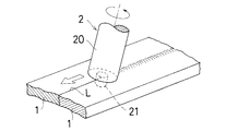
例えば、図1に示すように、ワークとして金属板(1)(1)同士を突き合わせて接合する場合、摩擦攪拌接合ツール(2)として円筒部(20)の先端に突軸状のプローブ(21)を有するものを用い、該ツール(2)を高速回転させながら接合線(L)の始端部に押し付けてプローブ(21)を埋入させ、矢印で示すように該接合線(L)に沿って移動させる。これにより、進行するプローブ(21)の前方側では摩擦熱と圧力によって金属板(1)(1)の素材が塑性流動し、攪拌混練されながらプローブ(21)の後方側へ漸次移行するが、この後方側では摩擦熱を失って急速に冷却固化するから、両金属板(1)(1)は素材金属が攪拌混練されて完全に一体化した状態で接合される。
【0004】
この場合、金属素材が塑性流動する温度は融点よりもかなり低く、接合は固相接合の範疇に入るから、接合過程を通してワークへの入熱量は少なく、且つ凝固収縮に伴う応力の発生もないから、接合部近傍の熱歪みによる変形や割れを生じにくいという利点がある。なお、図1のように摩擦攪拌接合ツール(2)側を移動させる代わりに、ワーク側を移動しつつ定位置に配備した加工ヘッドにて接合してもよい。
【0005】
従来、このような摩擦攪拌接合においては、接合対象とするワークの材質や肉厚等に応じて、摩擦攪拌接合ツールの仕様、該ツールの回転数、接合速度、該ツールの突っ込み深さ等の加工条件を最適となるように選択し、これら加工条件を接合開始から終了まで一定に維持して接合を行っていた。
【0006】
【発明が解決しようとする課題】
しかしながら、前記従来の摩擦攪拌接合方法では、形態や材質等より熱が溜まり易いワークを接合対象とするとき、接合の進行に伴って接合部位への入熱量が次第に増大することから、接合の開始部位と終了部位とで接合品位に差を生じるという問題があった。とりわけ、図2に示すように、直径φが60mm以下といった小径のパイプ材や棒材等のワーク(W)を周方向に沿って摩擦攪拌接合する場合、前記の接合品位の差が特に顕著に現れることから、実用上で大きな問題となっている。また、従来の摩擦攪拌接合方法においては、ツールの先端部をワークに埋入させ、接合のためにツール側又はワーク側の送りを開始するまでに時間がかかり、加工能率が悪いという難点もあった。
【0007】
この発明は、上述の事情に鑑みて、接合の開始部位から終了部位まで均等な接合品位が得られ、しかも高い加工能率を達成できる摩擦攪拌接合方法を提供することを目的としている。
【0008】
【課題を解決するための手段】
上記目的を達成するために、この発明の請求項1に係る摩擦攪拌接合方法は、接合の開始部位から終了部位までのワークへの入熱量を略一定に制御することを特徴としている。すなわち、ワークへの入熱量を均一化することにより、入熱状況の変化に起因した接合部位による接合状態の変動が抑えられ、塑性流動化した素材の硬化による摩擦攪拌組織の違いが少なくなり、接合の始端から終端まで均等な接合品位が得られる。特に、直径φが60mm以下の小径のパイプ材や棒材等のワーク(W)を周方向に沿って摩擦攪拌接合する場合に好適である。但し、これに限定されない。
【0009】
しかして、上記のようにワークへの入熱量を制御する手段として、請求項2の発明では摩擦攪拌接合ツールの回転数の変化、請求項3の発明では接合速度の変化、請求項4の発明では外部からのワークの加熱又は冷却、請求項5の発明では摩擦攪拌接合ツール側の加熱又は冷却、をそれぞれ利用するものとしている。
【0010】
また、請求項6の発明では、上記請求項1〜5のいずれかの摩擦攪拌接合方法において、接合中のワークの接合部又はその近傍の温度を計測し、この計測値に基づいて接合中のワークへの入熱量を制御するものとしている。この場合、ワークへの入熱量を接合中の温度計測値から直接的にフィードバックして制御するので、接合状況に即応して入熱量を補正して接合開始から終了までの入熱量を均等化できる。
【0011】
【発明の実施の形態】
この発明の摩擦攪拌接合方法では接合の開始部位から終了部位までのワークへの入熱量を略一定に制御するが、摩擦攪拌接合において該入熱量に関与する主要な因子としては、a)摩擦攪拌接合ツールの形状、b)該ツールの回転数、c)接合速度、d)該ツールの突っ込み深さ(ツールとワークの接触面積)が挙げられる。しかして、a)摩擦攪拌接合ツールの形状とd)該ツールの突っ込み深さは接合対象とするワークの接合部位の肉厚や形態によって定まるが、b)該ツールの回転数とc)接合速度は入熱量の制御因子として利用できる。
【0012】
すなわち、入熱不足の場合には、ツールの回転数を上げるか、接合速度を落とすことにより、入熱量を増加できる。逆に入熱過剰の場合には、ツールの回転数を下げるか、接合速度を速めることにより、入熱量を減少できる。ただし、摩擦攪拌接合を可能ならしめる上で、ツールの回転数と接合速度との比の許容範囲があるから、この許容範囲内で両者を変化させて入熱量制御を行うことになる。
【0013】
なお、ツールの回転数を変化させるには、は摩擦攪拌接合加工機における主軸の回転を制御すればよい。また接合速度を変化させるには、ツール側を移動させる接合方式では同主軸の移動速度を制御し、ワーク側を移動させる接合方式では該ワークの移動速度を制御すればよい。
【0014】
また、この発明では、ワークへの入熱量の制御手段として、ワークを加熱又は冷却する方法、ならびに摩擦攪拌接合ツール側を加熱又は冷却する方法も採用可能である。しかして、ワークの加熱にはヒーター加熱や熱風の吹き付け等を利用でき、またワークの冷却には低温流体を接触させて熱交換による排熱を促進する方法を適用できるが、これら以外の加熱又は冷却機構でも差し支えない。
【0015】
ツール側の加熱には、例えば図3(イ)に示すように、摩擦攪拌接合ツール(2)の円筒部(20)を包囲するジャケット(3)を設け、このジャケット(3)の内側にヒーター(4)を設置するか、同図(ロ)に示すように、同様のジャケット(3)内に加熱流体を流通させる方法を採用できる。またツール側の冷却には同図(ロ)のジャケット(3)内に低温流体を流通させる方法や、切削加工ツールに採用されるようなセンタースルー方式によるツール内部へのクーラントの流通方式を採用できる。
【0016】
これらの制御手段によって接合の開始部位から終了部位までのワークへの入熱量を略一定に制御するには、オフラインによって制御の指標を定める方法と、オンラインのフィードバック方式によって接合状況に即応して入熱量の補正を行う方法とがある。
【0017】
前者のオフラインによる方法では、実際に摩擦攪拌接合を行ったサンプルの接合状態を組織観察等で調べ、接合の開始部位から終了部位までを適当に区切った部位毎の最適な入熱条件を試行錯誤的に求め、判明した入熱条件に基づいて接合時の入熱制御を既述の制御手段によって行えばよい。
【0018】
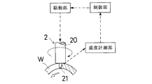
後者のオンラインによる方法では、図4に示すように、接合中のワーク(W)の接合部又はその近傍の温度を温度計測部で継続的に計測し、この計測値を制御部へ逐一入力し、制御部において予め設定した基準温度と計測値との差から必要とする入熱の加減量を求めると共に、前記制御手段の駆動部へ入熱を加減するための駆動信号を出力し、この駆動部の作動によって接合中のワーク(W)に対する入熱量を補正する。なお、このような自動制御によらず、前記温度の計測値に基づいて人為的に前記制御手段の駆動部を調整して、接合中のワーク(W)に対する入熱量を補正するようにしてもよい。しかして、上記の温度計測には、熱放射を測定するセンサー等を利用した非接触型の温度計測装置が好適であるが、接触型の温度計測装置も利用可能である。
【0019】
かくして摩擦攪拌接合におけるワークへの入熱量を均一化すれば、入熱状況の変化に起因した接合部位による接合状態の変動が抑えられるから、塑性流動化した素材の硬化による摩擦攪拌組織の違いが少なくなり、接合の始端から終端まで均等な接合品位となり、とりわけ小径のパイプ材や棒材等の周方向接合において好結果が得られる。
【0020】
一方、ワークへの入熱量を摩擦攪拌接合ツールの回転数の変化にて制御する方式を採用する場合、該ツールの先端部(プローブ)をワークに埋入させる際、ならびに埋入後に接合のためにツール側又はワーク側の送りを開始する際に、ツールの回転数を上げることにより、上記埋入の速度及び接合開始速度が速まるから、この時間短縮によって加工能率が向上する。またワークへの入熱量の制御に上記ツールの回転数又は接合速度を変化させる方式を採用すれば、加熱や冷却を行うための格別な外部装置が不要であるから、設備コスト的に有利である。
【0021】
【実施例】
6063−T5のアルミニウム材からなる直径50mm,厚さ4.0mmのパイプを接合対象とし、摩擦攪拌接合ツールとしてプローブ径が4mmのものを使用し、該ツールの回転数を接合の開始部位における1300rpmから終了部位における1000rpmまで漸減することにより、接合部位の温度を常時約480℃に維持してパイプの周方向に沿う摩擦攪拌接合を行った。そして、得られた接合品の接合部の組織を調べたところ、接合部の全体にわたって均質な摩擦攪拌組織を有しており、接合部位による品位の差がないことが確認された。
【0022】
【比較例】
前記実施例と同様のパイプ及び摩擦攪拌接合ツールを用い、該ツールの回転数を接合の開始部位から終了部位まで1100rpmで一定として、該パイプの周方向に沿う摩擦攪拌接合を行ったところ、接合部位の温度は開始部位の460℃から終了部位の490℃まで変化した。そして、得られた接合品の接合部の組織を調べたところ、接合の開始部位と終了部位とで摩擦攪拌組織に大きな違いがあり、接合品位が不均一であることが判った。
【0023】
【発明の効果】
請求項1の発明によれば、摩擦攪拌接合において、接合の開始部位から終了部位までのワークへの入熱量を略一定に制御することから、接合部の全体にわたって安定した摩擦攪拌組織で均等な接合品位が得られ、特に小径のパイプ材や棒材の周方向接合に好適な方法が提供される。
【0024】
請求項2の発明によれば、上記の摩擦攪拌接合方法において、ワークへの入熱量を摩擦攪拌接合ツールの回転数の変化にて制御することから、該入熱量の制御を加熱や冷却を行う場合のような格別な外部装置が不要で設備コスト的に有利である上、該ツールの先端部をワークに埋入させる際や、その埋入後にツール側又はワーク側の送りを開始する際の速度を速めて加工能率を向上できる。
【0025】
請求項3の発明によれば、上記の摩擦攪拌接合方法において、ワークへの入熱量を接合速度の変化にて制御することから、該入熱量の制御を加熱や冷却を行う場合のような格別な外部装置が不要となり、設備コスト的に有利になる。
【0026】
請求項4及び5の発明によれば、上記の摩擦攪拌接合方法において、ワークもしくは摩擦攪拌接合ツールの加熱又は冷却により、接合の開始部位から終了部位までのワークへの入熱量を略一定に制御できる。
【0027】
請求項6の発明によれば、上記の摩擦攪拌接合方法において、接合中のワークの接合部又はその近傍の温度の計測値から直接的にフィードバックして当該ワークへの入熱量を制御することから、接合状況に即応して入熱量を補正して接合開始から終了までの入熱量を均等化できる。
【図面の簡単な説明】
【図1】摩擦攪拌接合による金属板同士の接合を示す斜視図である。
【図2】摩擦攪拌接合によるパイプ材の接合を示す縦断側面図である。
【図3】この発明の摩擦攪拌接合方法におけるワークへの入熱量の制御手段を例示するものであり、(イ)図はヒーターによる加熱方式の摩擦攪拌接合ツールの概略縦断側面図、(ロ)図は流体による加熱又は冷却を行う同ツールの概略縦断側面図である。
【図4】この発明の摩擦攪拌接合方法におけるワークへの入熱量の制御手段を例示する模式図である。
【符号の説明】
1・・・・金属板
2・・・・摩擦攪拌接合ツール
20・・・円筒部
21・・・プローブ(先端部)
3・・・・ジャケット
4・・・・ヒーター
W・・・・ワーク[0001]
The present invention relates to a friction stir welding method in which workpieces are joined and integrated by relatively advancing the tip of a friction stir welding tool along a joining line between the workpieces while rotating in an embedded state.
[0002]
[Prior art]
In recent years, a friction stir welding method has appeared as a new joining means that replaces welding and brazing of metal materials. This joining method is, for example, as disclosed in Japanese Patent Publication No. 7-505090, when a probe made of a material harder than the workpiece (rod-like object) is slidably contacted with the workpiece, Because the workpiece material is plastically fluidized by the frictional heat and pressure generated at the sliding contact part, the probe is embedded in the workpiece and can be moved through the workpiece in this embedded state. It is a thing that makes use of.
[0003]
For example, as shown in FIG. 1, when a metal plate (1) (1) is abutted and joined as a workpiece, a protruding probe (21) is attached to the tip of a cylindrical portion (20) as a friction stir welding tool (2). ), Press the tool (2) against the starting end of the joining line (L) while rotating the tool (2) at a high speed to embed the probe (21), and follow the joining line (L) as indicated by the arrow. To move. As a result, the material of the metal plate (1) (1) is plastically flowed by the frictional heat and pressure on the front side of the traveling probe (21), and gradually moves to the rear side of the probe (21) while being stirred and kneaded. Since this rear side loses frictional heat and rapidly cools and solidifies, the two metal plates (1) and (1) are joined in a state where the raw metal is agitated and kneaded and is completely integrated.
[0004]
In this case, the temperature at which the metal material plastically flows is considerably lower than the melting point, and joining is in the category of solid-phase joining, so the amount of heat input to the workpiece is small throughout the joining process, and no stress is generated due to solidification shrinkage. There is an advantage that deformation and cracking due to thermal strain in the vicinity of the joint are unlikely to occur. In addition, instead of moving the friction stir welding tool (2) side as shown in FIG. 1, the workpiece may be joined by a machining head arranged at a fixed position while moving the workpiece side.
[0005]
Conventionally, in such friction stir welding, depending on the material and thickness of workpieces to be joined, the specifications of the friction stir welding tool, the rotational speed of the tool, the joining speed, the penetration depth of the tool, etc. The machining conditions were selected to be optimum, and the joining was performed while maintaining these machining conditions constant from the start to the end of the joining.
[0006]
[Problems to be solved by the invention]
However, in the conventional friction stir welding method, when workpieces that accumulate heat more easily than their form and material are to be joined, the amount of heat input to the joining portion gradually increases with the progress of joining, so the start of joining There is a problem in that there is a difference in bonding quality between the part and the end part. In particular, as shown in FIG. 2, when the workpiece (W) such as a pipe material or a bar material having a small diameter φ of 60 mm or less is friction stir welded along the circumferential direction, the difference in the joining quality is particularly remarkable. Since it appears, it is a big problem in practical use. Further, in the conventional friction stir welding method, it takes time to embed the tip of the tool in the work and start feeding on the tool side or work side for joining, and there is a problem that the machining efficiency is poor. It was.
[0007]
In view of the above-described circumstances, an object of the present invention is to provide a friction stir welding method capable of obtaining a uniform joining quality from a joining start site to an end site and achieving a high working efficiency.
[0008]
[Means for Solving the Problems]
In order to achieve the above object, the friction stir welding method according to
[0009]
Thus, as means for controlling the amount of heat input to the workpiece as described above, the invention according to
[0010]
Moreover, in invention of Claim 6, in the friction stir welding method in any one of the said Claims 1-5, the temperature of the junction part of the workpiece | work in joining or its vicinity is measured, Based on this measured value, it is in joining The amount of heat input to the workpiece is controlled. In this case, the amount of heat input to the workpiece is controlled by directly feeding back from the temperature measurement value during joining, so the amount of heat input from the start to the end of the joining can be equalized by correcting the amount of heat input according to the joining situation. .
[0011]
DETAILED DESCRIPTION OF THE INVENTION
In the friction stir welding method of the present invention, the heat input to the workpiece from the start part to the end part of the joint is controlled to be substantially constant. In the friction stir welding, the main factors involved in the heat input are as follows: a) friction stir The shape of the joining tool, b) the number of rotations of the tool, c) the joining speed, and d) the penetration depth of the tool (contact area between the tool and the workpiece). Thus, a) the shape of the friction stir welding tool and d) the penetration depth of the tool are determined by the thickness and form of the joining portion of the workpieces to be joined, but b) the rotational speed of the tool and c) the joining speed. Can be used as a control factor of heat input.
[0012]
That is, when the heat input is insufficient, the amount of heat input can be increased by increasing the number of rotations of the tool or decreasing the joining speed. On the contrary, when the heat input is excessive, the amount of heat input can be reduced by lowering the rotation speed of the tool or increasing the joining speed. However, in order to enable friction stir welding, there is an allowable range of the ratio between the rotational speed of the tool and the welding speed. Therefore, both are changed within this allowable range to control the heat input.
[0013]
In order to change the rotation speed of the tool, the rotation of the main shaft in the friction stir welding machine may be controlled. In order to change the joining speed, the moving speed of the spindle is controlled in the joining method in which the tool side is moved, and the moving speed of the workpiece is controlled in the joining method in which the workpiece side is moved.
[0014]
Moreover, in this invention, the method of heating or cooling a workpiece | work and the method of heating or cooling the friction stir welding tool side are also employable as a control means of the heat input amount to a workpiece | work. Thus, heater heating, hot air blowing, etc. can be used for heating the work, and methods for promoting exhaust heat by heat exchange by contacting a low temperature fluid can be applied for cooling the work. A cooling mechanism can be used.
[0015]
For heating on the tool side, for example, as shown in FIG. 3 (a), a jacket (3) surrounding the cylindrical portion (20) of the friction stir welding tool (2) is provided, and a heater is provided inside the jacket (3). (4) is installed, or a method of circulating a heating fluid in the same jacket (3) as shown in FIG. In addition, for cooling on the tool side, a low-temperature fluid is circulated in the jacket (3) in the same figure (b), or a coolant distribution method is used inside the tool by the center-through method used in cutting tools. it can.
[0016]
In order to control the amount of heat input to the workpiece from the start part to the end part of the joint with these control means, the control index is set off-line and the on-line feedback method is used to promptly input the heat. There is a method of correcting the amount of heat.
[0017]
In the former off-line method, the joining state of the sample that was actually subjected to friction stir welding was examined by structure observation, etc., and the optimum heat input conditions for each part that appropriately separated from the starting part to the ending part of the joining were trial and error. The heat input control at the time of joining may be performed by the control means described above based on the heat input conditions obtained and found.
[0018]
In the latter on-line method, as shown in FIG. 4, the temperature measurement unit continuously measures the temperature of the bonded portion of the workpiece (W) being bonded or the vicinity thereof, and this measured value is input to the control unit one by one. The controller calculates a required heat input / output amount from the difference between the reference temperature set in advance and the measured value, and outputs a drive signal for adjusting the heat input to the drive unit of the control means. The heat input to the workpiece (W) being joined is corrected by the operation of the part. Instead of such automatic control, the drive unit of the control means is artificially adjusted based on the measured value of the temperature to correct the heat input to the workpiece (W) being joined. Good. For the above temperature measurement, a non-contact type temperature measurement device using a sensor or the like for measuring thermal radiation is suitable, but a contact type temperature measurement device can also be used.
[0019]
Thus, if the heat input to the workpiece in friction stir welding is made uniform, fluctuations in the joining state due to the joining site due to changes in the heat input situation can be suppressed, so there is a difference in the friction stir structure due to hardening of the plastic fluidized material. As a result, the joint quality is uniform from the beginning to the end of the joining, and particularly good results can be obtained in the circumferential joining of small-diameter pipes and rods.
[0020]
On the other hand, when adopting a method that controls the amount of heat input to the workpiece by changing the rotation speed of the friction stir welding tool, it is necessary to bond the tip (probe) of the tool to the workpiece and after the implantation. When the feed on the tool side or the workpiece side is started, the embedding speed and the joining start speed are increased by increasing the number of rotations of the tool. Therefore, the machining efficiency is improved by shortening this time. In addition, if a method of changing the rotation speed or joining speed of the tool is used to control the amount of heat input to the workpiece, a special external device for heating and cooling is unnecessary, which is advantageous in terms of equipment cost. .
[0021]
【Example】
A pipe having a diameter of 50 mm and a thickness of 4.0 mm made of 6063-T5 aluminum material is used as a welding target, and a friction stir welding tool having a probe diameter of 4 mm is used. The rotation speed of the tool is 1300 rpm at the welding start site. The temperature at the joining portion was constantly maintained at about 480 ° C., and friction stir welding was performed along the circumferential direction of the pipe. And when the structure | tissue of the junction part of the obtained joining goods was investigated, it has a homogeneous friction stirring structure | tissue over the whole joining part, and it was confirmed that there is no difference in the quality by a joining part.
[0022]
[Comparative example]
Using the same pipe and friction stir welding tool as in the above example, the number of rotations of the tool was kept constant at 1100 rpm from the start part to the end part of the joint, and friction stir welding along the circumferential direction of the pipe was performed. The temperature of the site changed from 460 ° C. at the start site to 490 ° C. at the end site. And when the structure | tissue of the junction part of the obtained bonded article was investigated, it turned out that there is a big difference in a friction stir structure | tissue in the joining start part and completion | finish part, and joining quality is non-uniform | heterogenous.
[0023]
【The invention's effect】
According to the first aspect of the present invention, in the friction stir welding, the amount of heat input to the workpiece from the start part to the end part of the joint is controlled to be substantially constant. A bonding quality is obtained, and a method suitable for the circumferential bonding of small diameter pipe materials and bar materials is provided.
[0024]
According to the invention of
[0025]
According to the invention of
[0026]
According to the fourth and fifth aspects of the present invention, in the friction stir welding method described above, the amount of heat input to the work from the start part to the end part of the work is controlled to be substantially constant by heating or cooling the work or the friction stir welding tool. it can.
[0027]
According to the invention of claim 6, in the friction stir welding method described above, the amount of heat input to the workpiece is controlled by directly feeding back from the measured value of the temperature at or near the bonded portion of the workpiece being joined. The amount of heat input from the start to the end of welding can be equalized by correcting the amount of heat input in response to the joining situation.
[Brief description of the drawings]
FIG. 1 is a perspective view showing joining of metal plates by friction stir welding.
FIG. 2 is a longitudinal side view showing joining of pipe materials by friction stir welding.
FIG. 3 exemplifies a means for controlling the amount of heat input to a workpiece in the friction stir welding method of the present invention. FIG. 3A is a schematic longitudinal side view of a heating type friction stir welding tool using a heater. The figure is a schematic longitudinal side view of the tool for heating or cooling with a fluid.
FIG. 4 is a schematic view illustrating a means for controlling the amount of heat input to the workpiece in the friction stir welding method of the present invention.
[Explanation of symbols]
DESCRIPTION OF
3 ...
Claims (5)
Priority Applications (1)
| Application Number | Priority Date | Filing Date | Title |
|---|---|---|---|
| JP11411199A JP4286962B2 (en) | 1999-04-21 | 1999-04-21 | Friction stir welding method |
Applications Claiming Priority (1)
| Application Number | Priority Date | Filing Date | Title |
|---|---|---|---|
| JP11411199A JP4286962B2 (en) | 1999-04-21 | 1999-04-21 | Friction stir welding method |
Publications (3)
| Publication Number | Publication Date |
|---|---|
| JP2000301361A JP2000301361A (en) | 2000-10-31 |
| JP2000301361A5 JP2000301361A5 (en) | 2006-06-08 |
| JP4286962B2 true JP4286962B2 (en) | 2009-07-01 |
Family
ID=14629414
Family Applications (1)
| Application Number | Title | Priority Date | Filing Date |
|---|---|---|---|
| JP11411199A Expired - Fee Related JP4286962B2 (en) | 1999-04-21 | 1999-04-21 | Friction stir welding method |
Country Status (1)
| Country | Link |
|---|---|
| JP (1) | JP4286962B2 (en) |
Cited By (1)
| Publication number | Priority date | Publication date | Assignee | Title |
|---|---|---|---|---|
| KR20180023003A (en) | 2015-08-06 | 2018-03-06 | 가부시키가이샤 히타치 파워 솔루션즈 | Friction stir welding device and friction stir welding control method |
Families Citing this family (23)
| Publication number | Priority date | Publication date | Assignee | Title |
|---|---|---|---|---|
| DE10139687C1 (en) | 2001-08-11 | 2003-02-20 | Eads Deutschland Gmbh | Stirring tool for friction welding, has control which uses temperature values from the welding zone acquired by a sensor arranged with a measuring site in tool pin |
| US6780525B2 (en) * | 2001-12-26 | 2004-08-24 | The Boeing Company | High strength friction stir welding |
| US6776328B2 (en) * | 2002-09-17 | 2004-08-17 | The Boeing Company | Radiation assisted friction welding |
| JP2005074451A (en) * | 2003-08-29 | 2005-03-24 | Toyota Motor Corp | Friction stir welding method and friction stir welding apparatus |
| US6913186B2 (en) * | 2003-09-11 | 2005-07-05 | The Boeing Company | Apparatus and method for friction stir welding with a variable speed pin |
| JP4085988B2 (en) * | 2004-02-20 | 2008-05-14 | マツダ株式会社 | Rotating tool for friction welding equipment |
| WO2008023500A1 (en) * | 2006-08-21 | 2008-02-28 | Osaka University | Process for working metal members and structures |
| CN102814588B (en) | 2006-10-02 | 2015-03-04 | 日本轻金属株式会社 | Joining method |
| JP4957161B2 (en) * | 2006-10-02 | 2012-06-20 | 日本軽金属株式会社 | Friction stirring method |
| JP4740289B2 (en) * | 2008-06-23 | 2011-08-03 | 川崎重工業株式会社 | Friction stir welding equipment |
| JP5304583B2 (en) | 2009-10-09 | 2013-10-02 | 日本軽金属株式会社 | Rotating tool for inner corner joining and inner corner joining method using the same |
| JP5631162B2 (en) * | 2010-11-16 | 2014-11-26 | カルソニックカンセイ株式会社 | Friction stir welding method |
| JP5022502B2 (en) * | 2011-02-07 | 2012-09-12 | 川崎重工業株式会社 | Friction stir welding equipment |
| FR2971889B1 (en) * | 2011-02-18 | 2013-12-20 | Batscap Sa | METHOD FOR SEALING AN IMPREGNATION ORIFICE FROM AN ENERGY STORAGE ASSEMBLY |
| JP5966118B2 (en) * | 2011-08-17 | 2016-08-10 | 国立大学法人大阪大学 | Metal material processing method and metal material processing apparatus |
| US9751153B2 (en) * | 2012-03-30 | 2017-09-05 | Brigham Young University | Effort modulation for process control of friction stir operations |
| US8556156B1 (en) * | 2012-08-30 | 2013-10-15 | Apple Inc. | Dynamic adjustment of friction stir welding process parameters based on weld temperature |
| WO2014132335A1 (en) * | 2013-02-26 | 2014-09-04 | 株式会社 日立製作所 | Friction stir welding device and welding method |
| KR101534779B1 (en) * | 2014-04-08 | 2015-07-08 | 화천기공 (주) | controlling system of friction stir welding equipment and controlling methods thereby |
| JP6554029B2 (en) * | 2015-11-24 | 2019-07-31 | 川崎重工業株式会社 | Friction stir spot welding device and friction stir spot welding method |
| JP6624127B2 (en) * | 2017-03-13 | 2019-12-25 | Jfeスチール株式会社 | Surface modification apparatus, surface modification method, and method for producing metal material |
| EP3450082B1 (en) * | 2017-08-31 | 2020-12-16 | Mazak Corporation | Devices and methods for increased wear resistance during low temperature friction stir processing |
| CN111805106A (en) * | 2020-08-07 | 2020-10-23 | 张洪涛 | Stirring induction welding method and stirring head |
-
1999
- 1999-04-21 JP JP11411199A patent/JP4286962B2/en not_active Expired - Fee Related
Cited By (1)
| Publication number | Priority date | Publication date | Assignee | Title |
|---|---|---|---|---|
| KR20180023003A (en) | 2015-08-06 | 2018-03-06 | 가부시키가이샤 히타치 파워 솔루션즈 | Friction stir welding device and friction stir welding control method |
Also Published As
| Publication number | Publication date |
|---|---|
| JP2000301361A (en) | 2000-10-31 |
Similar Documents
| Publication | Publication Date | Title |
|---|---|---|
| JP4286962B2 (en) | Friction stir welding method | |
| US8011560B2 (en) | Apparatus and method of solid-state welding | |
| AU2016298789B2 (en) | Repair of pipeline welds using friction stir processing | |
| US6789722B2 (en) | Joining method and apparatus using frictional agitation | |
| JP4468125B2 (en) | Friction stir welding method and apparatus | |
| De Backer et al. | Temperature control of robotic friction stir welding using the thermoelectric effect | |
| TWI540012B (en) | Friction stir welding with temperature control | |
| JP5739804B2 (en) | Method for controlling tool temperature during friction stir welding using modifiable tool control parameters | |
| KR20040048426A (en) | Method For Friction Stir Welding | |
| US7455210B2 (en) | Processing operation control method, processing operation controller, computer program for carrying out the method, information storage medium storing the computer program | |
| EP1614497A1 (en) | Method and apparatus for repairing or building up surfaces on a workpiece while the workpiece is mounted on a machine tool | |
| JP2000301361A5 (en) | ||
| JP2007532314A (en) | Laser welding method and apparatus for parts formed from superalloys | |
| CN110524105B (en) | Rotary welding tool for friction welding and welding method | |
| KR102000691B1 (en) | A friction stir spot joining device and a friction stir spot joining method | |
| KR20140141700A (en) | Effort modulation for process control of friction stir operations | |
| Wei et al. | Understanding the behaviour of workpieces' bulk temperature during laser-assisted turning of Ti6Al4V alloy and heating of Al-SiC metal-matrix composite rods | |
| KR101366961B1 (en) | Laser assisted machining | |
| JP2005288474A (en) | Friction stir welding device and method | |
| JP4768418B2 (en) | Friction stir welding method | |
| Able et al. | Laser-assisted friction stir lap welding of aluminum | |
| JP3735298B2 (en) | Friction stir welding apparatus and friction stir welding method | |
| JP2004337860A (en) | Friction stir joining method and friction stir joining apparatus | |
| JP3724943B2 (en) | Main roller for multi-wire saw and manufacturing method thereof | |
| CN111889874A (en) | Stirring welding method for aluminum alloy and stainless steel |
Legal Events
| Date | Code | Title | Description |
|---|---|---|---|
| A521 | Written amendment |
Free format text: JAPANESE INTERMEDIATE CODE: A523 Effective date: 20060412 |
|
| A621 | Written request for application examination |
Free format text: JAPANESE INTERMEDIATE CODE: A621 Effective date: 20060412 |
|
| A977 | Report on retrieval |
Free format text: JAPANESE INTERMEDIATE CODE: A971007 Effective date: 20080910 |
|
| A131 | Notification of reasons for refusal |
Free format text: JAPANESE INTERMEDIATE CODE: A131 Effective date: 20080930 |
|
| A521 | Written amendment |
Free format text: JAPANESE INTERMEDIATE CODE: A523 Effective date: 20081128 |
|
| TRDD | Decision of grant or rejection written | ||
| A01 | Written decision to grant a patent or to grant a registration (utility model) |
Free format text: JAPANESE INTERMEDIATE CODE: A01 Effective date: 20090303 |
|
| A01 | Written decision to grant a patent or to grant a registration (utility model) |
Free format text: JAPANESE INTERMEDIATE CODE: A01 |
|
| A61 | First payment of annual fees (during grant procedure) |
Free format text: JAPANESE INTERMEDIATE CODE: A61 Effective date: 20090326 |
|
| FPAY | Renewal fee payment (event date is renewal date of database) |
Free format text: PAYMENT UNTIL: 20120403 Year of fee payment: 3 |
|
| R150 | Certificate of patent or registration of utility model |
Ref document number: 4286962 Country of ref document: JP Free format text: JAPANESE INTERMEDIATE CODE: R150 Free format text: JAPANESE INTERMEDIATE CODE: R150 |
|
| FPAY | Renewal fee payment (event date is renewal date of database) |
Free format text: PAYMENT UNTIL: 20120403 Year of fee payment: 3 |
|
| RD02 | Notification of acceptance of power of attorney |
Free format text: JAPANESE INTERMEDIATE CODE: R3D02 |
|
| FPAY | Renewal fee payment (event date is renewal date of database) |
Free format text: PAYMENT UNTIL: 20120403 Year of fee payment: 3 |
|
| FPAY | Renewal fee payment (event date is renewal date of database) |
Free format text: PAYMENT UNTIL: 20150403 Year of fee payment: 6 |
|
| LAPS | Cancellation because of no payment of annual fees |