JP4286536B2 - Isomerization method - Google Patents
Isomerization method Download PDFInfo
- Publication number
- JP4286536B2 JP4286536B2 JP2002534460A JP2002534460A JP4286536B2 JP 4286536 B2 JP4286536 B2 JP 4286536B2 JP 2002534460 A JP2002534460 A JP 2002534460A JP 2002534460 A JP2002534460 A JP 2002534460A JP 4286536 B2 JP4286536 B2 JP 4286536B2
- Authority
- JP
- Japan
- Prior art keywords
- reactor
- triptan
- process according
- reaction
- catalyst
- Prior art date
- Legal status (The legal status is an assumption and is not a legal conclusion. Google has not performed a legal analysis and makes no representation as to the accuracy of the status listed.)
- Expired - Fee Related
Links
Images
Classifications
-
- C—CHEMISTRY; METALLURGY
- C07—ORGANIC CHEMISTRY
- C07C—ACYCLIC OR CARBOCYCLIC COMPOUNDS
- C07C5/00—Preparation of hydrocarbons from hydrocarbons containing the same number of carbon atoms
- C07C5/22—Preparation of hydrocarbons from hydrocarbons containing the same number of carbon atoms by isomerisation
- C07C5/27—Rearrangement of carbon atoms in the hydrocarbon skeleton
- C07C5/2702—Catalytic processes not covered by C07C5/2732 - C07C5/31; Catalytic processes covered by both C07C5/2732 and C07C5/277 simultaneously
- C07C5/271—Catalytic processes not covered by C07C5/2732 - C07C5/31; Catalytic processes covered by both C07C5/2732 and C07C5/277 simultaneously with inorganic acids; with salts or anhydrides of acids
- C07C5/2718—Acids of halogen; Salts thereof; complexes thereof with organic compounds
-
- C—CHEMISTRY; METALLURGY
- C07—ORGANIC CHEMISTRY
- C07C—ACYCLIC OR CARBOCYCLIC COMPOUNDS
- C07C9/00—Aliphatic saturated hydrocarbons
- C07C9/14—Aliphatic saturated hydrocarbons with five to fifteen carbon atoms
- C07C9/16—Branched-chain hydrocarbons
- C07C9/21—2, 2, 4-Trimethylpentane
-
- C—CHEMISTRY; METALLURGY
- C10—PETROLEUM, GAS OR COKE INDUSTRIES; TECHNICAL GASES CONTAINING CARBON MONOXIDE; FUELS; LUBRICANTS; PEAT
- C10G—CRACKING HYDROCARBON OILS; PRODUCTION OF LIQUID HYDROCARBON MIXTURES, e.g. BY DESTRUCTIVE HYDROGENATION, OLIGOMERISATION, POLYMERISATION; RECOVERY OF HYDROCARBON OILS FROM OIL-SHALE, OIL-SAND, OR GASES; REFINING MIXTURES MAINLY CONSISTING OF HYDROCARBONS; REFORMING OF NAPHTHA; MINERAL WAXES
- C10G45/00—Refining of hydrocarbon oils using hydrogen or hydrogen-generating compounds
- C10G45/58—Refining of hydrocarbon oils using hydrogen or hydrogen-generating compounds to change the structural skeleton of some of the hydrocarbon content without cracking the other hydrocarbons present, e.g. lowering pour point; Selective hydrocracking of normal paraffins
-
- C—CHEMISTRY; METALLURGY
- C07—ORGANIC CHEMISTRY
- C07C—ACYCLIC OR CARBOCYCLIC COMPOUNDS
- C07C2527/00—Catalysts comprising the elements or compounds of halogens, sulfur, selenium, tellurium, phosphorus or nitrogen; Catalysts comprising carbon compounds
- C07C2527/06—Halogens; Compounds thereof
- C07C2527/133—Compounds comprising a halogen and vanadium, niobium, tantalium, antimonium or bismuth
Abstract
Description
【0001】
本発明は炭化水素の異性化方法に関するものである。特に本発明は、炭化水素を選択的に異性化させてトリプタン(2,2,3−トリメチルブタン)を得るための方法に関するものである。
【0002】
トリプタンは高分枝鎖の炭化水素であって、その高オクタン価によりモーターガソリンおよび航空ガソリンのための燃料添加剤として使用することができる。これは一般に脂肪族、脂環式および/またはアルキル芳香族の炭化水素を異性化触媒の存在下に異性化または反応させて製造される。この種の方法の例は米国特許第3766286号明細書(特許文献1)に記載されている。この特許公報は−30〜100℃の反応温度および0.1〜10時間の接触時間の使用を記載している。たとえば好適具体例は25℃にて5〜6時間にわたるn−へプタンの異性化を記載している。得られるトリプタン収率は0.4〜1.4重量%である。
【0003】
今回、反応温度および接触時間の慎重な選択によりトリプタンへの異性化法の選択率を増大させうることが突き止められた。
【0004】
【特許文献1】
米国特許第3766286号明細書
【0005】
本発明によればトリプタンの製造方法が提供され、前記方法は炭化水素供給原料を−50〜25℃の反応温度および0.01〜150時間の接触時間で異性化触媒と接触させて、異性化反応のトリプタン選択率を前記炭化水素供給原料の比率として少なくとも5%にすることにより炭化水素供給原料を異性化させることからなっている。
【0006】
好ましくは、反応温度は−30〜15℃、より好ましくは−25〜10℃、一層好ましくは−15〜5℃、特に好ましくは−10〜0℃である。
【0007】
接触時間は0.05〜50時間、好ましくは0.08〜24時間、より好ましくは0.1〜15時間、一層好ましくは1〜10時間、さらに好ましくは2〜7時間、特に好ましくは4〜6時間とすることができる。
【0008】
好ましくはトリプタン選択率は少なくとも7%、より好ましくは少なくとも9%である。たとえばトリプタン選択率は初期炭化水素供給原料の9〜60%とすることができる。
【0009】
用いる異性化触媒は好ましくはスーパー酸である。適するスーパー酸は式MXnのルイス酸からなるものを包含し、ここでMは遷移金属系、すなわち周期律表の第13、14、15もしくは16族から選択される元素であり、Xはハロゲンまたはフルオロ硫酸、トリフルオロメタンスルホン酸もしくはトリフルオロ酢酸から選択されるアニオンであり、nは3〜6の整数である。HX(ここでXは上記と同じ意味を有する)から選択されるブレンステッド酸およびその混合物も使用することができる。
【0010】
好ましくはMは周期律表の第13および15族から選択される。より好ましくはMはSbである。XはF、Cl、BrもしくはIとすることができ、好ましくはFもしくはClである。本発明の好適具体例においてMはその最高原子価状態で選択ハロゲンと共に使用される。たとえば最も好ましい本発明の具体例において、ルイス酸はSbF5である。
【0011】
Mは代案として遷移金属系から選択することもできる。Mが遷移金属である場合、これは好ましくは遷移金属系の第IVもしくはV族からの金属である。好適遷移金属はTi、Zr、Hf、V、Nb、Taを包含する。より好ましくはMはTi、NbおよびTaから選択され、特に好ましくはMはTaである。
【0012】
好ましくはブレンステッド酸はHF、トリフルオロメタンスルホン酸およびフルオロ硫酸から選択される。
【0013】
適する異性化触媒の好適例はHSO3F−SbF5およびSbF5−HFである。
【0014】
ブレンステッド酸とルイス酸とのモル比は約20:1〜1:5の範囲とすることができる。好ましくは5:1〜1:1のモル比が使用される。炭化水素の全使用量に対し用いられる触媒の量は炭化水素1重量部当たり約0.01〜100重量部の触媒の範囲とすることができる。好ましくは使用する触媒の量は炭化水素1重量部当たり1〜10重量部の触媒である。
【0015】
触媒はストレート液としてもしくは希釈溶液として使用することができ或いは固体支持体に吸着させることもできる。希釈触媒に関し、反応条件下にて不活性である任意の希釈剤を使用することができる。最適結果を得るには、希釈剤を予備処理してたとえば水、不飽和化合物などの触媒毒を除去することができる。典型的希釈剤は塩化スルフリルフルオライド、弗化スルフリル、弗素化炭化水素およびその混合物を包含する。フルオロ硫酸、硫酸、トリフルオロメタンスルホン酸などを包含するプロトン酸自身も希釈剤として使用することができる。希釈剤:触媒の容量比は約50:1〜1:1、好ましくは10:1〜2:1の範囲とすることができる。
【0016】
触媒は代案として適する固体キャリヤもしくは支持体と一体化させることもできる。反応条件下で触媒に対し実質的に不活性である任意の固体触媒支持体を使用することができる。支持体をたとえば加熱、化学処理もしくは被覆により予備処理して、存在しうる実質上全ての水および/またはヒドロキシル部位を除去することができる。活性支持体をたとえば三弗化アンチモンもしくは三弗化アルミニウムのような不活性材料で被覆することにより、活性支持体を不活性にすることができる。適する固体支持体は炭素(たとえばグラファイト)、たとえばスルホン化陽イオン交換樹脂のような弗化物処理もしくは被覆された樹脂、たとえばアルミナおよびアルミノシリケートのような弗化物処理された酸性カルサイド、およびたとえばゼオライト(たとえばフォージャサイト)のような酸耐性分子篩、を包含する。支持触媒は任意適する方法にて、たとえば乾燥混合、共沈もしくは含浸を包含する従来法により作成することができる。一つの具体例において、支持触媒は適する失活支持体にたとえば五弗化アンチモンのような金属弗化物を含浸させ、次いでたとえばフルオロ硫酸のようなブレンステッド酸を含浸させることにより作成される。
【0017】
支持触媒を用いる場合、ルイス酸と支持体との重量比は1:100〜1:10、好ましくは1:50〜1:35の範囲とすることができる。ブレンステッド酸と支持体との重量比は1:100〜1:10、好ましくは1:50〜1:35の範囲とすることができる。
【0018】
本発明の方法にて使用しうる炭化水素供給原料はパラフィン、アルキル置換芳香族炭化水素およびその混合物を包含する。ここに規定したパラフィンは、室温にて実質的に液相である脂肪族および脂環式の炭化水素を包含する。脂肪族炭化水素(直鎖および分枝鎖の材料)は1分子当たり4〜20個の炭素原子、好ましくは4〜8個の炭素原子を有することができ、n−ブタン、n−ペンタン、メチルペンタン、メチルヘキサンなどにより例示することができる。脂環式炭化水素(ナフテン類)は1分子当たり6〜20個の炭素原子、好ましくは6〜12個の炭素原子を有することができ、メチルシクロペンタン、ジメチルシクロペンタン、エチルシクロヘキサン、n−ペンチルシクロヘキサンなどにより例示することができる。反応条件に応じ、環の概要(すなわち環拡大もしくは縮小)を側鎖異性化と競合させることができる。アルキル置換芳香族炭化水素は1分子当たり7〜20個の炭素原子、好ましくは7〜12個の炭素原子を有することができ、原理的にたとえばキシレン、n−ブチルベンゼンなどの全ての異性化しうるアルキル芳香族もしくはポリアルキル芳香族炭化水素を包含することができる。環にて置換されたアルキル基の位置異性化および側鎖異性化の両者が反応条件に応じて生じうる。一般に従来の石油系炭化水素軽質ナフサ流にて見られる他の脂肪族もしくは非環式炭化水素も存在させることができる。
【0019】
本発明の好適具体例において、炭化水素供給原料はC5〜C9アルカン、たとえばC7アルカンで構成される。たとえばC7ナフサ流を用いることができる。適するC7アルカンの例はn−ヘプタン、2−メチルヘキサン、3−メチルヘキサン、エチルペンタン、2,3−ジメチルペンタン、3,3−ジメチルペンタン、2,2−ジメチルペンタンおよび2,4−ジメチルペンタンを包含する。炭化水素供給原料は実質上これらC7アルカンの1種で構成することができ、或いはこれらの2種もしくはそれ以上の混合物で構成することもできる。適するアルカン混合物は3−メチルへキサンと2,3−ジメチルペンタンとの混合物およびへプタンと2,4−ジメチルペンタンとの混合物を包含する。C7アルカンを、たとえばナフテン類(たとえば0〜40%、好ましくは30〜36%)のような他の数種の炭化水素およびたとえばトルエン(たとえば0〜10%、好ましくは2〜5%)のような芳香族物質と組合わせて存在させることができる。この種の組合せ物の例は25〜40%、好ましくは32〜38%のn−へプタン;10〜28%、好ましくは15〜23%のモノ−分枝鎖へプタン;5〜15%、好ましくは7〜11%の二分枝鎖へプタン;20〜40%、好ましくは32〜38%のナフテン類および0〜5%、たとえば2〜3%の芳香族物質からなっている。しかしながら好ましくは、供給物の芳香族含有量は低く、たとえば1%未満である。さらにC7アルカンをたとえばC5、C6およびC8アルカンのような他のアルカン類と一緒に供給物に存在させることもできる。この種の混合物の例は2〜6%、好ましくは4%のi−C5;3〜7%、好ましくは5%のC6;50〜70%、好ましくは60〜62%の2,3−ジメチルペンタン;20〜30%、好ましくは22〜26%の2,4−ジメチルペンタンおよび2〜8%、好ましくは4〜6%のC8からなるアルキレート−C7流である。
【0020】
炭化水素供給原料はたとえば水素および/またはイソブタンのような各種のクラッキング阻止剤もしくは調整剤を含有することができる。阻止剤は、異性化に際し生じうる過度の開裂反応を抑圧するよう作用する。水素もしくはイソブタンを使用する場合、これは好ましくは炭化水素供給物に基づき1〜3モル%の範囲の量で使用される。
【0021】
本発明の方法はバッチ式もしくは連続式の操作として行うことができる。一般に炭化水素相と触媒相との間の接触面積を増大させるべく抽出プロセスで常用される各種の手段を使用することができる。本発明の一つの具体例においては、炭化水素相と触媒相とを実質的に液相で接触させることができる。使用する装置は慣用のものとすることができる。たとえば装置は単一反応器たとえば流動床反応器または機械的攪拌器、超音波攪拌器、制限内径のジェットおよびターボミキサなどの効率的攪拌装置が設けられた多重反応器を備えることができる。炭化水素相と触媒相とを並流、交差流もしくは向流にて1個もしくはそれ以上の反応器に通過させることができる。未反応の反応体、触媒、阻止剤および反応のより重い生成物を所望の異性生成物から並びに相互に蒸留により分離して、全体的または部分的に異性化反応に戻すことができる。得られる生成物をたとえばアルキル化などによりさらに処理することもでき、或いは高オクタンガソリン配合剤として直接使用することもできる。
【0022】
トリプタン生成物は、任意適する技術を用いて生成混合物から回収することができる。その例は蒸留、抽出蒸留および選択的結晶化を包含する。膜も使用することができる。
【0023】
本発明の他面によればトリプタンの連続製造方法が提供され、前記方法は:
炭化水素供給原料を反応器中へ供給し、
供給原料をトリプタンからなる生成混合物を生成させるのに効果的な反応条件下で異性化触媒と接触させる
ことからなり、前記方法は生成混合物が少なくとも2つの液相からなり、一方の液相が他方よりも濃密であることを特徴とする。
【0024】
2つの液相を、たとえばデカンテーションのような単一の分離技術により分離することができる。この分離工程は連続式に或いは定期的間隔で行うことができる。
【0025】
2つの液相のうち、より濃密な液相は典型的には、異性化触媒と必要に応じ反応に用いられる任意の触媒希釈剤および/または触媒支持体とからなる極性もしくはイオン性の相である。より濃密な液相は反応器に保持することができる。代案として、より濃密な液相は反応器から回収して、好ましくは触媒希釈剤の少なくとも幾分かが回収相から除去された後に循環することもできる。さらに触媒は循環前に再生することもできる。2つの相のうち、より濃密な液相はエマルジョンとして存在させうることに注目すべきである。
【0026】
2つの液相の密度の低い方は典型的には、トリプタン生成物からなる極性の低いまたは非極性の相である。必要に応じ、たとえば反応の副生物のような他の油性生成物も第2相に存在することができる。可能な副生物の例は脂肪族炭化水素、たとえば3〜10個の炭素原子を有するものを包含する。他の副生物は芳香族および重合体の種類(C12以上)を包含する。この種の物質は弗素化し、或いはスルホン化することができる。好適具体例において、より密度の低い相はより密度の高い相から分離して反応器から回収される。
【0027】
2つの液相に加え、生成混合物はさらに蒸気相をも含むことができる。蒸気相はトリプタンと他の軽質脂肪族および芳香族炭化水素(たとえばC1〜C9)と水素とイソブタンとも含むことができる。好適具体例においては、蒸気相の少なくとも幾分かを反応器から抜き取る。蒸気相を縮合および蒸留により精製して、トリプタン含有流を生成することができる。
【0028】
蒸気相から回収されたトリプタンはモーターガソリンもしくは航空ガソリン、特に鉛除去モーターガソリンもしくは鉛除去航空ガソリンの製造に使用することができる。好適具体例においては、縮合蒸気をさらにたとえば蒸留により精製して、そのトリプタン濃度を増大させる。縮合蒸気の残部は反応器まで循環させることができる。次いで、少なくとも1種のモーターガソリンもしくは航空ガソリン添加剤をトリプタン向上生成物に添加することができる。得られた混合物をモーターガソリンもしくは航空ガソリン、好ましくは鉛除去モーターガソリンもしくは航空ガソリンのための添加剤として用いることができる。
【0029】
反応器の内容物を混合することもできる。この混合工程は、任意適する技術を用いて、たとえば機械攪拌器、超音波攪拌器を用いておよび/または気体もしくは液体を反応器中へ導入して行うことができる。任意適する機械攪拌器を用いることができる。反応器に通過させバブリングさせてその内容物を攪拌するガスは窒素、アルゴン、水素および軽質炭化水素(たとえばメタン、イソブタン)を包含する。追加として或いは代案として、混合は単に反応体および/または触媒が反応器中へ導入される結果として達成することもできる。
【0030】
混合は反応を容易化させるのに重要であるが、これは2つの液相の分離を阻止することもある。この問題は、攪拌の割合を減少させて軽減することができる。しかしながら好ましくは、生成混合物の少なくとも1部を少なくとも部分的に充分な攪拌力から遮蔽して、少なくとも2つの液相まで分離しうるようにする。
【0031】
従って好適具体例によればトリプタンの連続製造方法が提供され、前記方法は:
反応帯域と分離帯域とを有する反応器を設け、
炭化水素供給原料を反応器中へ供給し、
供給原料をトリプタンからなる生成混合物を生成させるのに効果的な反応条件下で異性化触媒と接触させる
ことからなり、前記方法は生成混合物の少なくとも1部を分離帯域に有して、これを少なくとも2つの液相まで分離させうることを特徴とする。
【0032】
反応帯域と分離帯域とは、好ましくは互いに流体連通する。反応帯域および分離帯域は装置の単一ピースに、たとえば反応帯域と分離帯域とを有する反応器を用いて、設けることができる。この配置の利点は、配管作業の要件を最小限に保って全反応器の材料コストを減少させることである。しかしながら、たとえば反応器を分離タンクに連結することにより装置の別々のピースを用いて反応帯域と分離帯域とを設けうることに注目すべきである。多重反応帯域および/または分離帯域を使用することができる。たとえば反応帯域と分離帯域とを有する反応器を別の分離タンクに連結することができる。
【0033】
本発明の好適具体例において、少なくとも1つの反応帯域と少なくとも1つの分離帯域とを有する反応器が用いられる。たとえば反応帯域と分離帯域とを、1つもしくはそれ以上のグリッドおよび/または多孔プレートを用いて分離することもできる。使用に際し生成混合物を反応帯域と分離帯域との間にグリッド/プレートにおける開孔もしくは目穴を介し自由流動させる。プレート/グリッドの一方の側における反応器の内容物を混合する場合、プレート/グリッドの反対側における反応器内容物を少なくとも部分的に充分な混合力から遮蔽する。かくして、グリッドの反対側における反応器内容物は分離帯域に存在し、少なくとも2つの相に分離することができる。攪拌器を1つもしくはそれ以上の邪魔板と組み合わせて用いることができ、邪魔板は反応器に位置せしめて反応帯域の混合作用を向上させることができる。
【0034】
グリッドもしくは多孔プレートを反応器に位置せしめて、水平に対し0〜60゜、好ましくは0〜45゜、より好ましくは0〜30゜、特に好ましくは0〜15゜に設置することができる。一つの具体例においては、グリッドもしくはプレートを実質上水平に位置せしめる。グリッドもしくはプレートより下の反応器内容物を攪拌して、分離帯域をグリッドもしくはプレート上方に形成させる。好ましくはグリッドもしくはプレートの縁部を反応器の内壁部に隣接させる。各縁部を離間させ或いは反応器の内壁部と物理係合させることもできる。
【0035】
上記具体例においては、反応器の内容物をグリッド/プレートの開口部もしくは目穴に比較的自由に流動させる。代案具体例においては、反応帯域から分離帯域への生成混合物の流れを機械インペラにより或いは反応器における任意の気泡のガス上昇作用により駆動させることができる。この方式における分離帯域への流過は、たとえば邪魔板もしくは堰を反応帯域と分離帯域との間に位置せしめると共にこれを横ぎる駆動力をどちらかの側における液体/蒸気または液体/液体界面レベルの制御により調節して制御することができる。かくして、生成混合物は反応帯域から分離帯域まで連続的または定期的間隔で流動する。
【0036】
炭化水素供給原料は、連続的または定期的間隔で導入することができる。好ましくは供給原料を反応器に連続的に供給する。供給原料は、触媒1kg当たり毎時25gより多い炭化水素の速度、たとえば触媒1kg当たり毎時50〜2500gの炭化水素の速度で反応器中へ供給することができる。
【0037】
本発明のこれらおよび他の局面を図面を参照して以下説明する。
【0038】
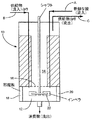
図1を参照して装置は反応器10を備え、これは反応帯域12と分離帯域14とにグリッド16により分割される。反応器には1対の邪魔板18、20と機械攪拌器22とを設ける。攪拌器22は反応帯域12中へ延びる。
【0039】
操作に際し、反応帯域12にはライン「A」を介しFSO3Hにおける30モル%のSbF5を充填する。ナフサからなる反応体流をもライン「B」を介し反応帯域12に連続供給すると共に、反応帯域12における内容物を機械撹拌器22により攪拌する。反応帯域12を−30〜10℃に維持すると共に、圧力を50バール未満に維持する。反応条件下でナフサを異性化してトリプタンからなる生成混合物を形成させる。
【0040】
反応器10の内容物を反応帯域12と分離帯域14との間にグリッド16の開口部(図示せず)を介し自由流動させる。しかしながら、グリッド16は分離帯域における生成混合物を少なくとも部分的に、攪拌器12によって生ずる攪拌力から遮蔽する。かくして、分離帯域14における生成混合物を沈降させると共に、より密度の低い相および濃密相に分離させる。より密度の低い相はトリプタン生成物を含有し、ライン「C」を介し分離帯域から連続回収される。濃密相は、反応帯域12における攪拌力のためエマルジョンとして存在することができる。
【0041】
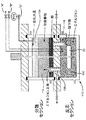
図2は本発明の実施例を実施するための代案装置を示す。この装置は反応器110を備え、これは反応帯域112と分離帯域114とにセパレータ116により分割される。セパレータ116は入り口118と出口120とを備える。反応器110には機械攪拌器122をも設け、これは反応帯域112中へ延びる。
【0042】
操作に際し、反応帯域112にはライン「A」を介しFSO3Hにおける30モル%のSbF5を充填する。ナフサを含む反応体流をもライン「B」を介し反応帯域112に連続供給すると共に、反応帯域112の内容物を機械攪拌器122により攪拌する。反応帯域112を−30〜10℃および50バール未満の圧力に維持する。反応条件下でナフサを異性化して、トリプタンを含む生成混合物を生成させる。
【0043】
反応帯域112の反応混合物は、攪拌器122により生じた攪拌力によりエマルジョンとして存在する。しかしながら、反応帯域112の反応混合物は反応帯域112から分離帯域114までセパレータ116の出口120を介し自由流動する。分離帯域にて反応混合物は、攪拌器122によって生ずる充分な攪拌力から遮蔽される。かくして、反応混合物を沈降させると共に3つの相(すなわち密度の低い相124、中間相126および濃密相128)に分離させる。より密度の低い相124はトリプタン生成物を含有すると共に、ライン「C」を介し分離帯域から連続回収される。濃密相128は酸触媒(FSO3Hにおける30モル%のSbF5)を含む。この相128の幾分かを入口118を介し反応帯域112中へ逆流させる。
【0044】
実施例
炭化水素(100ミリリットル)を、FSO3Hにおける30モル%のSbF5よりなる濃密触媒と−30〜10℃の温度にてバッチ式オートクレーブで均質混合した。良好な混合を確保するため邪魔板を用い、反応混合物を2000rpmにて撹拌した。試料を一定間隔にて反応混合物から除去すると共にガスクロマトグラフィーにより分析した。その結果を下表1に示す。
【0045】
【表1】

表から見られるように、トリプタンへのプロセスの選択率は用いる反応条件下にて少なくとも8.0%である。
【図面の簡単な説明】
【図1】 本発明による方法の実施例を行うのに適する装置の概略図である。
【図2】 本発明による方法の実施例を行うのに適する代案装置の概略図である。[0001]
The present invention relates to a hydrocarbon isomerization method. In particular, the present invention relates to a method for selectively isomerizing a hydrocarbon to obtain triptan (2,2,3-trimethylbutane).
[0002]
Triptan is a highly branched hydrocarbon and can be used as a fuel additive for motor gasoline and aviation gasoline due to its high octane number. This is generally produced by isomerizing or reacting aliphatic, alicyclic and / or alkyl aromatic hydrocarbons in the presence of an isomerization catalyst. An example of this type of method is described in US Pat. No. 3,766,286. This patent publication describes the use of a reaction temperature of -30 to 100 ° C and a contact time of 0.1 to 10 hours. For example, a preferred embodiment describes the isomerization of n-heptane at 25 ° C for 5-6 hours. The resulting triptan yield is 0.4-1.4% by weight.
[0003]
It has now been found that the selectivity of the isomerization process to triptan can be increased by careful selection of reaction temperature and contact time.
[0004]
[Patent Document 1]
US Pat. No. 3,766,286
According to the present invention there is provided a process for producing triptan, wherein the process comprises contacting a hydrocarbon feedstock with an isomerization catalyst at a reaction temperature of −50 to 25 ° C. and a contact time of 0.01 to 150 hours. The hydrocarbon feedstock is isomerized by setting the triptan selectivity of the reaction to at least 5% as a proportion of the hydrocarbon feedstock.
[0006]
Preferably, the reaction temperature is −30 to 15 ° C., more preferably −25 to 10 ° C., still more preferably −15 to 5 ° C., and particularly preferably −10 to 0 ° C.
[0007]
The contact time is 0.05 to 50 hours, preferably 0.08 to 24 hours, more preferably 0.1 to 15 hours, more preferably 1 to 10 hours, still more preferably 2 to 7 hours, and particularly preferably 4 to 4 hours. It can be 6 hours.
[0008]
Preferably the triptan selectivity is at least 7%, more preferably at least 9%. For example, the triptan selectivity can be 9-60% of the initial hydrocarbon feed.
[0009]
The isomerization catalyst used is preferably a super acid. Suitable super acids include those consisting of a Lewis acid of formula MX n , where M is a transition metal system, ie an element selected from
[0010]
Preferably M is selected from Groups 13 and 15 of the Periodic Table. More preferably, M is Sb. X can be F, Cl, Br or I, preferably F or Cl. In a preferred embodiment of the invention, M is used with a selected halogen in its highest valence state. For example, in the most preferred embodiment of the invention, the Lewis acid is SbF 5 .
[0011]
M can alternatively be selected from transition metal systems. When M is a transition metal, this is preferably a metal from group IV or V of the transition metal system. Suitable transition metals include Ti, Zr, Hf, V, Nb, Ta. More preferably M is selected from Ti, Nb and Ta, and particularly preferably M is Ta.
[0012]
Preferably the Bronsted acid is selected from HF, trifluoromethanesulfonic acid and fluorosulfuric acid.
[0013]
Preferred examples of suitable isomerisation catalysts are HSO 3 F-SbF 5 and SbF 5 -HF.
[0014]
The molar ratio of Bronsted acid to Lewis acid can range from about 20: 1 to 1: 5. Preferably a molar ratio of 5: 1 to 1: 1 is used. The amount of catalyst used relative to the total amount of hydrocarbon used can range from about 0.01 to 100 parts by weight of catalyst per part by weight of hydrocarbon. Preferably the amount of catalyst used is 1 to 10 parts by weight of catalyst per part by weight of hydrocarbon.
[0015]
The catalyst can be used as a straight liquid or as a dilute solution or can be adsorbed on a solid support. With respect to the diluted catalyst, any diluent that is inert under the reaction conditions can be used. For optimal results, the diluent can be pretreated to remove catalyst poisons such as water, unsaturated compounds, and the like. Typical diluents include sulfuryl chloride fluoride, sulfuryl fluoride, fluorinated hydrocarbons and mixtures thereof. Protonic acids themselves including fluorosulfuric acid, sulfuric acid, trifluoromethanesulfonic acid and the like can also be used as diluents. The volume ratio of diluent: catalyst can range from about 50: 1 to 1: 1, preferably 10: 1 to 2: 1.
[0016]
The catalyst can alternatively be integrated with a suitable solid carrier or support. Any solid catalyst support that is substantially inert to the catalyst under the reaction conditions can be used. The support can be pretreated, for example by heating, chemical treatment or coating, to remove substantially all water and / or hydroxyl sites that may be present. By coating the active support with an inert material such as antimony trifluoride or aluminum trifluoride, the active support can be rendered inactive. Suitable solid supports are carbon (eg graphite), eg fluoride treated or coated resins such as sulfonated cation exchange resins, fluoride treated acid calsides such as alumina and aluminosilicates, and zeolites (eg Acid resistant molecular sieves such as faujasite). The supported catalyst can be made by any suitable method, for example by conventional methods including dry mixing, coprecipitation or impregnation. In one embodiment, the supported catalyst is made by impregnating a suitable deactivated support with a metal fluoride such as antimony pentafluoride and then with a Bronsted acid such as fluorosulfuric acid.
[0017]
When using a supported catalyst, the weight ratio of Lewis acid to support can be in the range of 1: 100 to 1:10, preferably 1:50 to 1:35. The weight ratio of Bronsted acid to support can be in the range of 1: 100 to 1:10, preferably 1:50 to 1:35.
[0018]
Hydrocarbon feedstocks that can be used in the process of the present invention include paraffins, alkyl-substituted aromatic hydrocarbons and mixtures thereof. Paraffin as defined herein includes aliphatic and alicyclic hydrocarbons that are substantially in the liquid phase at room temperature. Aliphatic hydrocarbons (straight and branched materials) can have 4 to 20 carbon atoms, preferably 4 to 8 carbon atoms per molecule, and include n-butane, n-pentane, methyl Examples thereof include pentane and methylhexane. The alicyclic hydrocarbons (naphthenes) can have 6 to 20 carbon atoms per molecule, preferably 6 to 12 carbon atoms, methylcyclopentane, dimethylcyclopentane, ethylcyclohexane, n-pentyl. Examples thereof include cyclohexane. Depending on the reaction conditions, the ring profile (ie ring expansion or contraction) can be made to compete with side chain isomerization. Alkyl-substituted aromatic hydrocarbons can have 7 to 20 carbon atoms, preferably 7 to 12 carbon atoms per molecule, and can in principle be all isomerized, for example xylene, n-butylbenzene, etc. Alkyl aromatic or polyalkyl aromatic hydrocarbons can be included. Both positional and side chain isomerization of alkyl groups substituted on the ring can occur depending on the reaction conditions. Other aliphatic or acyclic hydrocarbons commonly found in conventional petroleum hydrocarbon light naphtha streams can also be present.
[0019]
In a preferred embodiment of the present invention, the hydrocarbon feedstock is comprised of C 5 -C 9 alkanes, for example C 7 alkane. For example it is possible to use a C 7 naphtha stream. Examples of suitable C 7 alkanes n- heptane, 2-methyl hexane, 3-methyl hexane, ethyl pentane, 2,3-dimethyl pentane, 3,3-dimethyl pentane, 2,2-dimethyl pentane and 2,4-dimethyl Includes pentane. Hydrocarbon feed may be constituted by one substantially these C 7 alkanes, or may be constituted by these two or more thereof. Suitable alkane mixtures include a mixture of 3-methylhexane and 2,3-dimethylpentane and a mixture of heptane and 2,4-dimethylpentane. The C 7 alkanes, e.g. naphthenes (eg 0-40%, preferably 30-36%) several other hydrocarbons and such as toluene (eg 0 to 10%, preferably 2-5% is) such as the Can be present in combination with such aromatic substances. Examples of such combinations are 25-40%, preferably 32-38% n-heptane; 10-28%, preferably 15-23% mono-branched heptane; 5-15%, Preferably 7-11% bi-branched heptane; 20-40%, preferably 32-38% naphthenes and 0-5%, for example 2-3% aromatics. Preferably, however, the aromatic content of the feed is low, for example less than 1%. Further it may be present in the other of the feed with alkanes such as the C 7 alkanes e.g. C 5, C 6 and C 8 alkanes. Examples of such mixtures is 2-6%, preferably 4% i-C 5; 3~7%, preferably 5% C 6; 50-70% 2,3 preferably from 60 to 62% - dimethyl pentane; 20% to 30%, preferably 22 to 26% of 2,4-dimethyl pentane and 2% to 8%, alkylate -C 7 stream which preferably consists of 4% to 6% of C 8.
[0020]
The hydrocarbon feedstock can contain various cracking inhibitors or modifiers such as hydrogen and / or isobutane. Inhibitors act to suppress excessive cleavage reactions that can occur during isomerization. If hydrogen or isobutane is used, it is preferably used in an amount ranging from 1 to 3 mol% based on the hydrocarbon feed.
[0021]
The process of the present invention can be carried out as a batch or continuous operation. In general, various means commonly used in extraction processes can be used to increase the contact area between the hydrocarbon phase and the catalyst phase. In one embodiment of the present invention, the hydrocarbon phase and the catalyst phase can be contacted in a substantially liquid phase. The equipment used can be conventional. For example, the apparatus may comprise a single reactor such as a fluidized bed reactor or a mechanical stirrer, an ultrasonic stirrer, a multi-reactor provided with an efficient stirrer such as a limited bore jet and a turbomixer. The hydrocarbon phase and the catalyst phase can be passed through one or more reactors in cocurrent, crossflow or countercurrent. Unreacted reactants, catalysts, inhibitors and heavier products of the reaction can be separated from the desired isomeric product and from each other by distillation and returned to the isomerization reaction in whole or in part. The resulting product can be further processed, such as by alkylation, or can be used directly as a high-octane gasoline blend.
[0022]
The triptan product can be recovered from the product mixture using any suitable technique. Examples include distillation, extractive distillation and selective crystallization. Membranes can also be used.
[0023]
According to another aspect of the present invention, there is provided a process for the continuous production of triptan, the process comprising:
Feed hydrocarbon feedstock into the reactor,
The feedstock is contacted with an isomerization catalyst under reaction conditions effective to produce a product mixture consisting of triptan, wherein the process comprises at least two liquid phases, one liquid phase being the other It is characterized by being denser.
[0024]
The two liquid phases can be separated by a single separation technique such as decantation. This separation step can be carried out continuously or at regular intervals.
[0025]
Of the two liquid phases, the denser liquid phase is typically a polar or ionic phase consisting of an isomerization catalyst and optionally any catalyst diluent and / or catalyst support used in the reaction. is there. A denser liquid phase can be retained in the reactor. Alternatively, the denser liquid phase can be recovered from the reactor and preferably recycled after at least some of the catalyst diluent has been removed from the recovery phase. Furthermore, the catalyst can be regenerated before circulation. It should be noted that the denser liquid phase of the two phases can exist as an emulsion.
[0026]
The lower of the two liquid phases is typically a less polar or non-polar phase consisting of a triptan product. If desired, other oily products such as reaction by-products can also be present in the second phase. Examples of possible by-products include aliphatic hydrocarbons, such as those having 3 to 10 carbon atoms. Other by-products include the type of aromatic and the polymer (C 12 or higher). This type of material can be fluorinated or sulfonated. In a preferred embodiment, the less dense phase is separated from the more dense phase and recovered from the reactor.
[0027]
In addition to the two liquid phases, the product mixture can further comprise a vapor phase. The vapor phase can also contain triptan and other light aliphatic and aromatic hydrocarbons (eg C 1 -C 9 ), hydrogen and isobutane. In a preferred embodiment, at least some of the vapor phase is withdrawn from the reactor. The vapor phase can be purified by condensation and distillation to produce a triptan containing stream.
[0028]
Triptan recovered from the vapor phase can be used for the production of motor gasoline or aviation gasoline, in particular lead removal motor gasoline or lead removal aviation gasoline. In a preferred embodiment, the condensation vapor is further purified, for example by distillation, to increase its triptan concentration. The remainder of the condensation vapor can be circulated to the reactor. At least one motor gasoline or aviation gasoline additive can then be added to the triptan enhancement product. The resulting mixture can be used as an additive for motor gasoline or aviation gasoline, preferably lead removal motor gasoline or aviation gasoline.
[0029]
It is also possible to mix the contents of the reactor. This mixing step can be performed using any suitable technique, for example using a mechanical stirrer, ultrasonic stirrer and / or introducing a gas or liquid into the reactor. Any suitable mechanical stirrer can be used. Gases that are bubbled through the reactor and agitating the contents include nitrogen, argon, hydrogen and light hydrocarbons (eg, methane, isobutane). Additionally or alternatively, mixing can be achieved simply as a result of reactants and / or catalysts being introduced into the reactor.
[0030]
Mixing is important to facilitate the reaction, but this may prevent the separation of the two liquid phases. This problem can be alleviated by reducing the rate of stirring. Preferably, however, at least a portion of the product mixture is at least partially shielded from sufficient agitation so that it can be separated into at least two liquid phases.
[0031]
Thus, according to a preferred embodiment, a continuous process for the production of triptan is provided, said process comprising:
Providing a reactor having a reaction zone and a separation zone;
Feed hydrocarbon feedstock into the reactor,
Comprising contacting the feedstock with an isomerization catalyst under reaction conditions effective to produce a product mixture comprising triptan, the process comprising at least a portion of the product mixture in a separation zone, which is at least It can be separated into two liquid phases.
[0032]
The reaction zone and the separation zone are preferably in fluid communication with each other. The reaction zone and separation zone can be provided in a single piece of equipment, for example using a reactor having a reaction zone and a separation zone. The advantage of this arrangement is that it reduces the material costs of the entire reactor while keeping plumbing requirements to a minimum. However, it should be noted that the reaction zone and the separation zone can be provided using separate pieces of equipment, for example by connecting the reactor to a separation tank. Multiple reaction zones and / or separation zones can be used. For example, a reactor having a reaction zone and a separation zone can be connected to another separation tank.
[0033]
In a preferred embodiment of the invention, a reactor having at least one reaction zone and at least one separation zone is used. For example, the reaction zone and the separation zone can be separated using one or more grids and / or perforated plates. In use, the product mixture is allowed to flow freely between the reaction zone and the separation zone through apertures or eye holes in the grid / plate. When mixing reactor contents on one side of the plate / grid, the reactor contents on the opposite side of the plate / grid are at least partially shielded from sufficient mixing force. Thus, the reactor contents on the opposite side of the grid are in the separation zone and can be separated into at least two phases. A stirrer can be used in combination with one or more baffles, which can be positioned in the reactor to improve the mixing action of the reaction zone.
[0034]
A grid or a perforated plate can be placed in the reactor and installed at 0 to 60 °, preferably 0 to 45 °, more preferably 0 to 30 °, particularly preferably 0 to 15 ° with respect to the horizontal. In one embodiment, the grid or plate is positioned substantially horizontally. The reactor contents below the grid or plate are agitated to form a separation zone above the grid or plate. Preferably the edge of the grid or plate is adjacent to the inner wall of the reactor. Each edge can be spaced apart or physically engaged with the inner wall of the reactor.
[0035]
In the above embodiment, the contents of the reactor are allowed to flow relatively freely into the grid / plate openings or eye holes. In alternative embodiments, the flow of the product mixture from the reaction zone to the separation zone can be driven by a mechanical impeller or by the gas raising action of any bubbles in the reactor. The flow into the separation zone in this way is, for example, placing a baffle or weir between the reaction zone and the separation zone and the driving force across it on the liquid / vapor or liquid / liquid interface level on either side It is possible to adjust and control by controlling. Thus, the product mixture flows from the reaction zone to the separation zone at continuous or regular intervals.
[0036]
The hydrocarbon feed can be introduced continuously or at regular intervals. Preferably, the feed is continuously fed to the reactor. The feed can be fed into the reactor at a rate of greater than 25 grams per hour per kilogram of catalyst, for example, between 50 and 2500 grams per hour per kilogram of catalyst.
[0037]
These and other aspects of the invention are described below with reference to the drawings.
[0038]
With reference to FIG. 1, the apparatus comprises a
[0039]
In operation,
[0040]
The contents of the
[0041]
FIG. 2 shows an alternative device for implementing an embodiment of the present invention. The apparatus comprises a
[0042]
In operation,
[0043]
The reaction mixture in the
[0044]
EXAMPLE <br/> hydrocarbon (100 mL) were intimately mixed in a batch autoclave at a temperature of FSO 3 consists of SbF 5 of 30 mol% in H dense catalyst and -30~10 ℃. A baffle was used to ensure good mixing and the reaction mixture was stirred at 2000 rpm. Samples were removed from the reaction mixture at regular intervals and analyzed by gas chromatography. The results are shown in Table 1 below.
[0045]
[Table 1]
As can be seen from the table, the selectivity of the process to triptan is at least 8.0% under the reaction conditions used.
[Brief description of the drawings]
FIG. 1 is a schematic diagram of an apparatus suitable for carrying out an embodiment of the method according to the invention.
FIG. 2 is a schematic diagram of an alternative apparatus suitable for carrying out an embodiment of the method according to the invention.
Claims (19)
炭化水素供給原料を反応器中へ供給し、
供給原料をトリプタンからなる生成混合物を生成させるのに有効な反応条件下で異性化触媒と接触させることからなり、
生成混合物は少なくとも2つの液相からなり、一方の液相が他方よりも濃密であることを特徴とする請求項8記載の方法。The process is a continuous production of triptan, said process further feeding a hydrocarbon feedstock into the reactor;
Contacting the feedstock with an isomerization catalyst under reaction conditions effective to produce a product mixture comprising triptan;
9. The method of claim 8, wherein the product mixture comprises at least two liquid phases, one liquid phase being denser than the other.
炭化水素供給原料を反応器中へ供給し、
供給原料をトリプタンからなる生成混合物を生成されるのに有効な反応条件下で異性化触媒と接触させることからなり、
前記方法は分離帯域に生成混合物の少なくとも1部を有して、これを少なくとも2つの液相に分離しうることを特徴とする請求項9〜14のいずれか一項に記載の連続法。Providing one reactor having a reaction zone and a separation zone;
Feed hydrocarbon feedstock into the reactor,
Contacting the feedstock with an isomerization catalyst under reaction conditions effective to produce a product mixture comprising triptan;
15. A continuous process according to any one of claims 9 to 14, wherein the process comprises at least a part of the product mixture in a separation zone, which can be separated into at least two liquid phases.
Applications Claiming Priority (3)
| Application Number | Priority Date | Filing Date | Title |
|---|---|---|---|
| GB0024888A GB0024888D0 (en) | 2000-10-11 | 2000-10-11 | Isomerisation process |
| GB0117829A GB0117829D0 (en) | 2001-07-21 | 2001-07-21 | Isomerisation process |
| PCT/GB2001/004461 WO2002031089A1 (en) | 2000-10-11 | 2001-10-05 | Isomerisation process |
Publications (3)
| Publication Number | Publication Date |
|---|---|
| JP2004511493A JP2004511493A (en) | 2004-04-15 |
| JP2004511493A5 JP2004511493A5 (en) | 2005-12-22 |
| JP4286536B2 true JP4286536B2 (en) | 2009-07-01 |
Family
ID=26245137
Family Applications (1)
| Application Number | Title | Priority Date | Filing Date |
|---|---|---|---|
| JP2002534460A Expired - Fee Related JP4286536B2 (en) | 2000-10-11 | 2001-10-05 | Isomerization method |
Country Status (10)
| Country | Link |
|---|---|
| US (1) | US6855857B2 (en) |
| EP (1) | EP1326947B1 (en) |
| JP (1) | JP4286536B2 (en) |
| CN (1) | CN1238472C (en) |
| AT (1) | ATE277147T1 (en) |
| AU (1) | AU2001292117A1 (en) |
| CA (1) | CA2425390A1 (en) |
| DE (1) | DE60105835T2 (en) |
| ES (1) | ES2227273T3 (en) |
| WO (1) | WO2002031089A1 (en) |
Families Citing this family (3)
| Publication number | Priority date | Publication date | Assignee | Title |
|---|---|---|---|---|
| GB0121105D0 (en) | 2001-08-31 | 2001-10-24 | Bp Oil Int | An improved process for the production of triptane |
| US20060270885A1 (en) * | 2005-05-31 | 2006-11-30 | Boyer Christopher C | Normal heptane isomerization |
| US7825287B2 (en) * | 2008-03-28 | 2010-11-02 | The Regents Of The University Of California | Process for production of triptane and triptene |
Family Cites Families (14)
| Publication number | Priority date | Publication date | Assignee | Title |
|---|---|---|---|---|
| US2583739A (en) | 1946-01-22 | 1952-01-29 | California Research Corp | Catalytic isomerization of isoheptanes to triptane |
| US3766286A (en) | 1971-06-25 | 1973-10-16 | Exxon Research Engineering Co | Process for the isomerization of hydrocarbons |
| BE789430A (en) | 1971-10-15 | 1973-03-29 | Inst Francais Du Petrole | LOW TEMPERATURE SATURATED HYDROCARBONS ISOMERIZATION PROCESS |
| US3839489A (en) * | 1972-02-28 | 1974-10-01 | Phillips Petroleum Co | Isomerization with asf5 and/or sbf5 and with trifluoromethanesulfonic acid or hf and high h2 partial pressure |
| US3962133A (en) | 1974-12-12 | 1976-06-08 | Mobil Oil Corporation | Graphite intercalation |
| FR2300749A1 (en) | 1975-02-14 | 1976-09-10 | Inst Francais Du Petrole | Low temp. isomerisation of alkanes and naphthalenes - with catalyst contg. Lewis acid, perfluoroalkane sulphonic acid and hydrofluoric acid |
| US4025459A (en) | 1975-05-14 | 1977-05-24 | Exxon Research And Engineering Company | Noble metal hydrogenation catalysts promoted by fluoride containing acids |
| JPS5910258B2 (en) | 1978-11-21 | 1984-03-07 | 三菱瓦斯化学株式会社 | Hydrocarbon conversion methods |
| IT1129809B (en) | 1979-03-26 | 1986-06-11 | Ugine Kuhlmann | CATALYTIC COMPOSITION FOR THE CONVERSION OF HYDROCARBONS AND PROCEDURE FOR THE DEHYDRATION OF PERFLUOROALCANSOLPHONIC ACIDS INTENDED TO BE PART OF THE BEAUTIFUL COMPOSITION |
| US4229611A (en) * | 1979-04-11 | 1980-10-21 | Exxon Research & Engineering Co. | Isomerization alkylation systems |
| US4246094A (en) * | 1979-06-11 | 1981-01-20 | Standard Oil Company (Indiana) | Process for upgrading naphtha hydrocarbons |
| US4472268A (en) * | 1983-01-18 | 1984-09-18 | El Paso Products Company | Upgrading of natural gasoline with trifluoromethane sulfonic acid, hydrofluoric acid and Lewis acid catalyst |
| FR2771419B1 (en) | 1997-11-25 | 1999-12-31 | Inst Francais Du Petrole | HIGH-INDEX OCTANE ESSENCES AND THEIR PRODUCTION BY A PROCESS COMBINING HYDRO-ISOMERIZATION AND SEPARATION |
| ITMI981630A1 (en) | 1998-07-16 | 2000-01-16 | Agip Petroli | SUPERACID CATALYST FOR THE HYDROISOMERIZATION OF N-PARAFFIN |
-
2001
- 2001-10-05 JP JP2002534460A patent/JP4286536B2/en not_active Expired - Fee Related
- 2001-10-05 WO PCT/GB2001/004461 patent/WO2002031089A1/en active IP Right Grant
- 2001-10-05 ES ES01972341T patent/ES2227273T3/en not_active Expired - Lifetime
- 2001-10-05 US US10/398,765 patent/US6855857B2/en not_active Expired - Fee Related
- 2001-10-05 CN CNB018202101A patent/CN1238472C/en not_active Expired - Fee Related
- 2001-10-05 EP EP01972341A patent/EP1326947B1/en not_active Expired - Lifetime
- 2001-10-05 AT AT01972341T patent/ATE277147T1/en not_active IP Right Cessation
- 2001-10-05 AU AU2001292117A patent/AU2001292117A1/en not_active Abandoned
- 2001-10-05 DE DE60105835T patent/DE60105835T2/en not_active Expired - Lifetime
- 2001-10-05 CA CA002425390A patent/CA2425390A1/en not_active Abandoned
Also Published As
| Publication number | Publication date |
|---|---|
| EP1326947A1 (en) | 2003-07-16 |
| AU2001292117A1 (en) | 2002-04-22 |
| DE60105835T2 (en) | 2005-02-10 |
| WO2002031089A1 (en) | 2002-04-18 |
| CA2425390A1 (en) | 2002-04-18 |
| CN1479774A (en) | 2004-03-03 |
| DE60105835D1 (en) | 2004-10-28 |
| US6855857B2 (en) | 2005-02-15 |
| EP1326947B1 (en) | 2004-09-22 |
| ATE277147T1 (en) | 2004-10-15 |
| US20030187316A1 (en) | 2003-10-02 |
| JP2004511493A (en) | 2004-04-15 |
| CN1238472C (en) | 2006-01-25 |
| ES2227273T3 (en) | 2005-04-01 |
Similar Documents
| Publication | Publication Date | Title |
|---|---|---|
| JP4542427B2 (en) | Paraffin alkylation | |
| US20110319693A1 (en) | Ionic liquid catalyzed alkylation with ethylene in ethylene containing gas streams | |
| US10369556B2 (en) | Integrated process for gasoline production | |
| US4094924A (en) | Process for the alkylation of light paraffins with lower olefins | |
| EP0584760B1 (en) | Alkylation catalyst regeneration | |
| JP4286536B2 (en) | Isomerization method | |
| PL90268B1 (en) | ||
| US3911043A (en) | Plural stages of HF alkylation of isoparaffin with a mono-olefin | |
| US3867473A (en) | Two stages of isoparaffin-olefin alkylation with recycle of alkylate-containing hydrocarbon | |
| US11643373B1 (en) | Integrated reactor for ionic liquid alkylation using bio-ethylene feedstock | |
| TWI790441B (en) | Flexible production of gasoline and jet fuel in alkylation reactor | |
| US5345027A (en) | Alkylation process using co-current downflow reactor with a continuous hydrocarbon phase | |
| RU2102369C1 (en) | Method of alkylation of paraffin stock with olefins | |
| CN1040872C (en) | Process for upgrading a paraffinic feedstock | |
| US3985823A (en) | Isoparaffin-olefin alkylation with HF alkylation and isomerization in a soaking zone | |
| NO309857B1 (en) | Process for the preparation of an isobutane- and isohexane-containing product | |
| US5969206A (en) | Reverse emulsion aliphatic alkylation process with catalyst-olefin premixing | |
| EP0725770B1 (en) | Process for upgrading a paraffinic feedstock | |
| US9096483B2 (en) | Catalytic isomerization of hexanes using ionic liquids | |
| US2570407A (en) | Reactions involving the use of hydrogen halides | |
| USRE28724E (en) | Isoparaffin alkylation with a lighter olefin and subsequently with a heavier olefin | |
| SU799642A3 (en) | Method of producing high octane component of motor fuel | |
| CA1064971A (en) | Hydrogen fluoride alkylation process | |
| US3538175A (en) | Hf alkyation process | |
| JP3589669B2 (en) | Paraffin raw material reforming method |
Legal Events
| Date | Code | Title | Description |
|---|---|---|---|
| A521 | Request for written amendment filed |
Free format text: JAPANESE INTERMEDIATE CODE: A523 Effective date: 20041004 |
|
| A621 | Written request for application examination |
Free format text: JAPANESE INTERMEDIATE CODE: A621 Effective date: 20041004 |
|
| A977 | Report on retrieval |
Free format text: JAPANESE INTERMEDIATE CODE: A971007 Effective date: 20080905 |
|
| A131 | Notification of reasons for refusal |
Free format text: JAPANESE INTERMEDIATE CODE: A131 Effective date: 20080917 |
|
| A521 | Request for written amendment filed |
Free format text: JAPANESE INTERMEDIATE CODE: A523 Effective date: 20081216 |
|
| TRDD | Decision of grant or rejection written | ||
| A01 | Written decision to grant a patent or to grant a registration (utility model) |
Free format text: JAPANESE INTERMEDIATE CODE: A01 Effective date: 20090304 |
|
| A01 | Written decision to grant a patent or to grant a registration (utility model) |
Free format text: JAPANESE INTERMEDIATE CODE: A01 |
|
| A61 | First payment of annual fees (during grant procedure) |
Free format text: JAPANESE INTERMEDIATE CODE: A61 Effective date: 20090325 |
|
| FPAY | Renewal fee payment (event date is renewal date of database) |
Free format text: PAYMENT UNTIL: 20120403 Year of fee payment: 3 |
|
| R150 | Certificate of patent or registration of utility model |
Free format text: JAPANESE INTERMEDIATE CODE: R150 |
|
| LAPS | Cancellation because of no payment of annual fees |