JP4283039B2 - Automobile traveling control device and automobile - Google Patents
Automobile traveling control device and automobile Download PDFInfo
- Publication number
- JP4283039B2 JP4283039B2 JP2003156618A JP2003156618A JP4283039B2 JP 4283039 B2 JP4283039 B2 JP 4283039B2 JP 2003156618 A JP2003156618 A JP 2003156618A JP 2003156618 A JP2003156618 A JP 2003156618A JP 4283039 B2 JP4283039 B2 JP 4283039B2
- Authority
- JP
- Japan
- Prior art keywords
- brake
- vehicle
- pedal
- force
- mode
- Prior art date
- Legal status (The legal status is an assumption and is not a legal conclusion. Google has not performed a legal analysis and makes no representation as to the accuracy of the status listed.)
- Expired - Lifetime
Links
Images


Description
【0001】
【発明の属する技術分野】
本発明は、自動車の走行制御装置およびその方法、およびそれを用いた自動車に関し、特に渋滞時などの緩加減速走行を含む車間距離制御オートクルーズに関連する。
【0002】
【従来の技術】
自車両と前方車両(含む障害物など)との距離をレーダにより検出し、安全な車間距離になるようにエンジン,モータ,変速機,ブレーキなどを自動制御する技術の開発が進んでいる。渋滞時の緩加減速走行を含む車間距離制御オートクルーズ(以下、「ACC」:Adaptive Cruise Controlとする)がその例である。
【0003】
その場合の安全性をより高く確保するために、発進・加速のみ自動制御を実行し、減速・停止は運転者の意思によるというシステムが考えられている。
【0004】
その一例として、現行の油圧ブレーキシステムを用いてブレーキペダルのみの操作により減速・停止および発進・加速を行うシステムが考えられている。
【0005】
例えば特開平4-38600号公報には、渋滞時などの緩加減速走行モードに設定された場合に、ブレーキ操作のみの1ペダル走行によって車両を停止・発進を実現するものが開示されている。つまり、ブレーキ操作が無い場合は、車両の走行速度を目標の走行速度になるよう駆動力を制御し、ブレーキ操作がある場合は、前記駆動力が進行方向に加わらないよう制御するようにしたものである。
【0006】
【発明が解決しようとする課題】
前記従来技術によれば、現行のブレーキ操作機構を用いて、車両の停止・発進をブレーキ操作のみの1ペダルで実現するために、ブレーキペダル操作により減速・停止を実行し、ブレーキペダルを離すと発進・加速するというような、いわばON−OFF的な使い方しかできなかった。
【0007】
右折や左折時において、ブレーキをかけて減速・停止した後に右折または左折方向への移動は、素早く実現できることが安全性の観点で望ましい。
【0019】
【課題を解決するための手段】
本発明は、道路上における自動車の通行帯が進行方向の左側と定められている国または地域における前記ワンペダルモードで走行中の右折または右転回の場合または自動車の通行帯が進行方向の右側と定められている国または地域における前記ワンペダルモードで走行中の左折または左転回の場合は設定加速度が直進の場合から、予め設定された直進より大きな加速度に遷移するように構成する。
【0020】
本発明の走行制御装置を搭載した自動車は一般道路でも適用できるため、交差点などでの右折、左折する状況が生まれる。その場合、日本のような左側通行の国においては右折する場合、対向車線を走行してくる自動車の間隔をぬって安全を確かめつつ素早い右折が必要とされる場合が多い。そういった場合、本発明のように右折時に、予め右折用に設定された直進より大きな加速度に遷移するようにした方がより安全に右折できる。また、右側通行の国あるいは地域においては逆に左折時に、予め左折用に設定された直進より大きな加速度に遷移するようにした方がより安全に左折することができる。
【0021】
また、本発明は、ワンペダルモードで走行中の右折または右転回、左折または左転回の場合は設定加速度が直進の場合から、予め設定された直進より大きな加速度に遷移するように構成する。このような設定とすることにより、自動車の通行帯が進行方向の左側と定められている国または地域における信号のない交差点、例えば一時停止地点で左折する場合は、右折の場合と同様に、安全を確かめつつ素早い左折が必要とされる場合が多い。そういった場合、本発明のように左折時にも、予め右折または左折用に設定された直進より大きな加速度に遷移するようにした方がより安全に左折することができる。また、右側通行の国あるいは地域においては逆に右折時に、予め右折または左折用に設定された直進より大きな加速度に遷移するようにした方がより安全に右折することができる。
【0022】
好ましくは上記設定加速度が遷移する時期は、前記右折または左折の進行方向への方向指示器のスイッチを入れたときである。これにより運転者の簡単な操作で加速度をそのときだけ変更することができる。
【0031】
【発明の実施の形態】
図1は、本発明の一実施の形態を示す自動車の機能ブロック図である。
【0032】
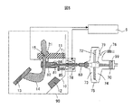
自動車1には、ブレーキ操作機構2と、エンジン3,モータ4を含む変速機5,ブレーキ装置6a〜6dおよびタイヤ7a〜7dから成る制動駆動システム8と、入力信号(後述)に対応して前記制動駆動システム8を制御する制御装置9が搭載されている。
【0033】
まず、前記ブレーキ操作機構2について説明する。自動車1のボディ10には支持部11およびストッパー12が取り付けられている。ボディ10に取り付けられた支持部11には、ブレーキペダル13の操作により動作する第1レバー14に固定された回転軸15が前記支持部11に対して回動可能に支持されている。また、前記回転軸15に対して回動可能な第2レバー16が設けられている。
【0034】
前記ブレーキペダル13の操作により、第2レバー16と第1レバー14に取り付けられた部材17の爪18が接触した場合、第2レバー16が動作する。第2レバー16とボディ10には、第1ペダル反力機構(リターンスプリング)19が設けられている。また、前記第1レバー14と第2レバー16の間にも第2ペダル反力機構(リターンスプリング)20が設けられており、第1ペダル反力機構19の反力は第2ペダル反力機構20の反力よりも大きく設定する。
【0035】
つまり、運転者(図示省略)がブレーキペダル13を第2ペダル反力機構20の反力より大きく、且つ第1ペダル反力機構19の反力より小さく操作した場合、第2レバー16は動作せずに第1レバー14のみが動作し、部材17の爪18と第2レバー16が接触して停止している。ここで、「第2レバー16は動作せず」とは、第2レバー16が全く動かない場合を意味するのではなく、制動力が発生しない限りにおいては第2レバー16の多少の動きを許容する。
【0036】
その後、運転者が第1ペダル反力機構19の反力に打ち勝つようにブレーキペダル13を操作した場合は、接触していた爪18と第2レバー16が一体となって回動し、前記第1レバー14が前記ストッパー12に接触するまで動作する。
【0037】
また、回転軸15の回転角度を検出するためのブレーキペダル操作量センサ21が第2レバー16に取り付けられており、部材17の爪18と第2レバー16が接触するまでの操作量および第1レバー14がストッパー12に接触するまでの操作量を出力する。
【0038】
ここでは、ブレーキの操作量を検出する操作量センサ21を用いた例で説明するが、ブレーキペダル13の踏み込み力(踏力)を検出するブレーキ操作力(踏力)センサを用いても良い。
【0039】
次に、前記エンジン3,モータ4を含む変速機5,ブレーキ装置6a〜6dおよびタイヤ7から成る制動駆動システム8の構成について説明する。
【0040】
エンジン3には、吸入空気量を制御する電子制御スロットル22,目標の空燃比(吸入空気量/供給燃料量)を達成するように吸入空気量に見合う燃料量を供給する燃料噴射弁23およびエンジン3が効率良く燃焼するための点火を実行する点火装置24が設けられている。
【0041】
ここでは、ガソリンエンジンの例を示すが、その他、ディーゼルエンジン,ガスタービンなどのエンジンを適用することも可能である。また、ガソリンエンジンも、吸気管に燃料を噴射するポート燃料噴射エンジン,筒内に直接燃料を噴射する筒内燃料噴射エンジン,吸排気弁の電子制御により燃焼効率を向上するミラーエンジンなどが実用化されており、どのエンジンを適用しても問題はない。但し、地球環境問題の点から、燃費低減と排気ガス低減が両立するエンジンシステムが最も適していることは言うまでもない。
【0042】
変速機5は、2軸・常時かみ合い式歯車をベースとしたモータ4付きの自動変速機である。モータ4は、ジェネレータ機能を有しており、バッテリ25から電気エネルギーを与えることにより運動エネルギーを放出してエンジン3の始動およびタイヤ7の駆動を実行し、エネルギー回生などにより運動エネルギーを与え電気エネルギーに変換してバッテリ25に貯蔵する。
【0043】
高速時は、高速用ドライブギア26と高速用ドリブンギア27によりエンジン3とモータ4の出力トルクをタイヤ7に伝達する。高速用ドライブギア26は、変速機入力軸4に固定されている。高速用ドリブンギア27は、ギア切換アシストクラッチ29により変速機出力軸30との締結・解放が可能になっている。
【0044】
同様に、中速および低速時は、中速用ドライブギア31,低速用ドライブギア33と中速用ドリブンギア32,低速用ドリブンギア34によりエンジン3とモータ4の出力トルクをタイヤ7に伝達する。中速用ドライブギア31および低速用ドライブギア33は、変速機入力軸4に固定されている。また、中速と低速のギア切り換えおよびモータ4の締結・解放は、それぞれ第1ドッグクラッチ35および第2ドッグクラッチ36により実行する。
【0045】
一般に、これらのドッグクラッチは、締結時の滑り損失がなく、伝達効率が高いことで知られている。特に、中速と低速のギア切り換え時は、エンジン3あるいはモータ4のトルクが変速機出力軸30に伝達されずに変速ショック(トルク低下)が発生するために、ギア切換アシストクラッチ29を滑り制御して高速用歯車列を介してトルク伝達を実行する。
【0046】
また、モータ4のみの走行の場合には、エンジン3を切り離す必要があり、また、エンジン3による発進のために、発進クラッチ37を変速機入力軸28に設けた。この発進クラッチ37は、クラッチディスクをフライホイール(図示省略)とプレッシャープレート(図示省略)との間に挟みつけてトルクを伝達する形式のいわゆる乾式クラッチを用いることができる。
【0047】
前記全てのクラッチの操作は、油圧アクチュエータ38によって行われる。なお、前記全てのクラッチに湿式多板クラッチや電磁クラッチなどの従来から知られているものを任意に選択して使用することができる。
【0048】
また、ここでは、クラッチの操作に油圧アクチュエータを用いているが、超音波モータ,直流モータ,交流モータなどの電気アクチュエータを用いても良い。
【0049】
更に、変速機5は、車両を停止させるためのブレーキクラッチ39を有している。
【0050】
ブレーキ装置6a〜6dは、車輪軸40a〜41dに固定したブレーキディスク41a〜41しおよびブレーキパッド(図示省略)を設けたキャリパー42a〜42dとブレーキ駆動モータ43a〜43dを備える。このブレーキ装置6a〜6dは、環境の変化、例えば、雨、長時間の放置などにより前記ブレーキディスク41a〜41dとブレーキパッド間の摩擦係数が大幅に変化する。よって、低速,停止時の車間距離制御オートクルーズの性能が低下し、スムースな停止と目標車間距離精度の両立が困難になる。
【0051】
これに対して、変速機5に設けたブレーキクラッチ39は、環境変化が生じた場合でも摩擦係数の変化がほとんどなく良好な低速,停止時の車間距離制御オートクルーズ性能が得られる。
【0052】
次に、制動駆動システム8を制御する制御装置9について説明する。
【0053】
制御装置9は、エンジン3,変速機5,ブレーキ装置6a〜6dを制御する制御ユニット(図示省略)および制動駆動システム8の全体を管理する制御ユニット(図示省略)を有し、それぞれがネットワークで通信するように接続されている。
【0054】
また、制御装置9は、ブレーキペダル操作量センサ21の信号β,走行モード設定スイッチ44の信号,駆動力(加速度)設定スイッチ45の信号,アクセルペダル操作量センサの信号α,右前輪回転センサ信号Nfr,左前輪回転センサ信号Nfl,右後輪回転センサ信号Nrr,左後輪回転センサ信号Nrl,エンジン回転数信号Ne,モータ回転数信号Nm,ミリ波レーダシステム80などから得られる前方車両との車間距離信号Sおよび前方車両との相対速度信号Vr,運転者自ら目標速度を設定可能な速度設定スイッチ50の信号などを入力する。
【0055】
そして、制御装置9は、これらの入力信号に基づき、エンジン3,変速機5およびブレーキ装置6a〜6dを制御して車両の加速,減速,発進,停止および定速走行を実現する。
【0056】
次に、図2のブレーキ操作量(力)に対する制動・駆動力の関係を示す特性図および図3の制御フローチャートを用いてブレーキ操作機構2の機能を説明する。 制御装置9は、図3における処理ステップ60において、前述したようにブレーキペダル操作量センサ21の信号β,走行モード設定スイッチ44の信号,駆動力(加速度)設定スイッチ45の信号,アクセルペダル操作量センサの信号α,右前輪回転センサ信号Nfr,左前輪回転センサ信号Nfl,右後輪回転センサ信号Nrr,左後輪回転センサ信号Nrl,エンジン回転数信号Ne,モータ回転数信号Nm,ミリ波レーダシステム80などから得られる前方車両との車間距離信号Sおよび前方車両との相対速度信号Vr,運転者自ら目標速度を設定可能な速度設定スイッチ50の信号などを入力して制御処理を実行する。この制御処理で使用する車速Noは、右前輪回転センサ信号Nfr,左前輪回転センサ信号Nfl,右後輪回転センサ信号Nrr,左後輪回転センサ信号Nrlを平均した値に基づいて求めるようにしているが、別途、車速センサを使用して入力するようにしても良い。
【0057】
本発明は、ブレーキペダル13から運転者が足を離すことなく車両の発進・停止を実現することを目的としている。つまり、前記走行モード切換スイッチ44に追従モード(車間距離制御オートクルーズ)を設定した場合(図3における処理ステップ61の判定結果がYのとき)を想定している。
【0058】
まず、ブレーキ操作量の機能の1つとしてフットレスト機能範囲(図2におけるA範囲)を持たせた。つまり、第2ペダル反力機構20の反力をブレーキペダル荷重(ブレーキペダル13+回転軸15までの第1レバー14)に運転者の足荷重を加えた力よりも小さく設定する。反対に、第1ペダル反力機構19の反力は、ブレーキペダル荷重に運転者の足荷重を加えた力よりも大きく、あるいは以上に設定する。これにより、運転者は、ブレーキペダル13の上に足を置いていても制動力を発生することがないので、車間距離制御オートクルーズ実行(加速,定速)時の運転負担が軽減する。
【0059】
その後、例えば、緩減速(図2におけるB範囲)が必要な場合、運転者はブレーキペダル13を第1ペダル反力機構19の反力に打ち勝つように踏み込む。この図2のB範囲では、駆動力の低下機能を実行する。つまり、エンジントルクをアイドリング状態あるいは変速比を制御することによりエンジンブレーキを働かせる。
【0060】
また、図1に示すように、モータ4を搭載した車両(HEV:ハイブリッド自動車)では、モータ4によるエネルギー回生を行って緩減速度を得ることも可能である。
【0061】
更に、ブレーキペダル13の操作量を大きく(図2におけるC範囲)すると、ブレーキ装置6a〜6d(ブレーキクラッチ39)が作動して大きな制動力(減速度)が得られる。
【0062】
以上の制動力は、ラインFを通る制動力増加ライン(図3における処理ステップ62の判定結果がNのとき)である。ラインFでの制動は、図3における処理ステップ62に示すようにブレーキ操作量βがゼロでなく、且つ処理ステップ63のΔβ(前回のβ−今回のβ)が予め設定したGラインへの変更値(−k1:k1は正の値)より大きい場合(Gラインへの変更がない場合)に実行される。そして、処理ステップ64において目標制動力Deがブレーキ操作量β,車速No,ブレーキパッド・ディスク間の摩擦係数μの関数f1により演算される。
【0063】
次に、処理ステップ63の判定においてΔβが−k1より小さくなった場合、つまりラインGに移行した場合について説明する。
【0064】
この場合には処理ステップ65に進み、Δβが予め設定したFライン変更値(k2:k2は正の値)より小さい場合には、処理ステップ66に進む。処理ステップ66では、図2におけるB,C範囲においてGラインをベースとし、目標制動力Deをブレーキ操作量β,車速No,ブレーキパッド・ディスク間の摩擦係数μの関数f2により演算する。
【0065】
また、図2におけるA範囲では、加速するための目標駆動力Acをブレーキ操作量β,車速No,前記駆動力設定スイッチ45で設定された目標駆動力Ttar,前記速度設定スイッチ50で設定された目標最大速度Vtar,車間距離Sおよび相対速度Vr,前記摩擦係数μの関数f3により演算する。
【0066】
また、ラインFおよびGの傾斜などは、それぞれ運転者が任意に決定することができ、運転者の意図する加速・減速感が実現できるようにする。最大制動力は、安全性優先のために変更できないようにする。
【0067】
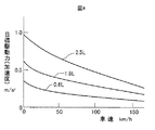
図4は、駆動力設定スイッチ45により設定される目標駆動力(加速度)特性を示している。この特性は、前方に車両がない場合、つまり車速一定制御(クルーズコントロール)を想定している。また、車速に応じて変化し、エンジン3の排気量が2.5Lの場合は、例えば3段階(2.5L:最大駆動力,1.8L,0.6L)の駆動力特性が選択できる。
【0068】
これらの駆動力特性は、ナビゲーション・VICS(Vehicle Information and Communication System)などのインフラ情報・HEO(長楕円軌道衛星)システムなどから得られる道路環境、例えば高速道路,山岳道路,市街地などの変化でも設定可能にしている。
【0069】
図5は、油圧ブレーキシステムをベースにして構成したブレーキ操作機構2の実施の形態を示している。前述のシステムのブレーキ制御は、ブレーキペダル13の操作量(力)を制御装置9に入力し、この制御装置9内で目標の制動力を演算してブレーキ装置6a〜6dを操作する、いわゆるBBW(Brake By Wire)である。これに対して、図5に示したシステムは、従来から存在する油圧ブレーキを利用したものである。ブレーキ操作機構90の基本部分は、図1に示したブレーキ操作機構2の構成と同一であり、重複する説明は省略する。ここでは、マスタシリンダ70の駆動により油圧を発生させ車両を制動する油圧ブレーキシステムに、ブレーキ操作機構90を付加した場合の実施例について説明する。
【0070】
ブレーキ操作機構90の第1レバー14には、ブレーキペダル13の操作に相応して水平方向に動作するオペレーティングロッド71(ペダル側ロッド82,ブレーキ側ロッド83)が取り付けられている。オペレーティングロッド71の先端部には、ダイヤフラム72により2室(第1室73および第2室74)に分けられたシリンダ駆動装置75が設けられている。
【0071】
第2室74は、エンジンの吸気管(図示省略)にチェックバルブ76を介して連結されており、エンジンが始動されると負圧になる。また、第1室73と第2室74を区切るダイヤフラム72には穴79を設け、2室の圧力が同一になっている。よって、マスタシリンダ70のピストン99は停止している。
【0072】
運転者がブレーキペダル13を踏み込むと、オペレーティングロッド71が図5における右側に移動し、ロッド71のブレーキ側ロッド83の先端部とシリンダ駆動装置75との間に隙間ができる。また、破線で示すように、オペレーティングロッド71のブレーキ側ロッド83がダイヤフラム72と接触し、結果的に穴79による空気の移動を遮断する。よって、第1室73の圧力が大気圧となり、第2室74との圧力差によりダイヤフラム72が右側に移動し、ピストン99の動作によりマスタシリンダ70の油圧が上昇する。これにより、運転者は小さなブレーキ操作力にてブレーキを操作することができる。
【0073】
また、オペレーティングロッド71には、比例ソレノイド78が設けられており、制御装置9からの信号によって自動的にブレーキがかけられるようになっている。
【0074】
更に、図2に示したブレーキ操作範囲Aではオペレーティングロッド71の先端部とシリンダ駆動装置75との間に隙間ができないような遅れ機構81を設けている。この遅れ機構81は、ペダル側ロッド82とブレーキ側ロッド83の間に第3ペダル反力機構84を設けている。また、ブレーキ側ロッド83には、第4ペダル反力機構85を設けている。
【0075】
第3ペダル反力機構84の反力は、ブレーキペダル荷重(ブレーキペダル13+回転軸15までの第1レバー14+ペダル側ロッド82)に運転者の足荷重を加えた力よりも小さく設定する。反対に、第4ペダル反力機構85の反力は、ブレーキペダル荷重に運転者の足荷重を加えた力よりも大きく、あるいは以上に設定する。これにより、運転者は、ブレーキペダル13の上に足を置いていても制動力を発生することがない(フットレスト機能)ので車間距離制御オートクルーズ実行(加速、定速)時の運転負担が軽減する。
【0076】
つまり、図1に示した実施の形態と同様にこの実施の形態でもブレーキペダル13から運転者が足を離すことなく車両の発進・停止を実現することができる。
【0077】
図6は、追従モードからマニュアルモードへの切り換え手法である。本発明では、制御装置9に入力される走行モード設定スイッチ44の設定により追従モードとマニュアルモードの切り換えが可能である。
【0078】
人間は、一般的に、連続で一つの行動を実行し、その行動に慣れた後に別の行動を実行する場合には、この別の行動に慣れるまで時間がかかる。よって、追従モードで長時間運転した後にマニュアルモードに急に移行すると、運転者は、前の走行モードの走行感覚から抜けきれず、誤った操作を実行する可能性があり危険である。
【0079】
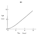
そこで、図6に示すように、追従モードON時間の長さ(Ton)に応じて、追従モードスイッチがOFFしてから実際に追従モードがOFFされるまでの時間(Toff)を変化させるようにする。つまり、追従モード時間が長い場合は、Toffを長く設定し、このToffに設定された期間は、追従モードにおける運転支援を継続するようにした。また、マニュアルモードから追従モードへ切り換える際は、安全運転制御への切り換えとなるので、マニュアルモードスイッチがOFFしてから実際にOFFするまでの時間は、Toffよりも短くて良い(時間ゼロを含む)。
【0080】
このようにすることにより、追従モードで長時間運転した後にマニュアルモードに移行した場合の運転者の誤操作が低減し、安全なモード切り換えを実現することができる。
【0081】
図7は、表示部における表示内容の一例である。本発明のような追従モードとマニュアルモードなどの複数の走行モードが存在する場合には、運転者は現在どのような運転を実行しているか、本当に故障していないのかなどが認識できないと不安になる可能性がある。
【0082】
そこで、運転席の前方のダッシュボード(図示省略)に表示部90を設け、制御装置9からの信号によって図7に示すような内容を表示して運転者に安心感を与えることが望ましい。表示部90には、走行路91,前方の認識物体92(車両など),自車両93,現在の走行モード94,故障内容95,前方物体との車間距離97および現在車速96などを表示する。
【0083】
車間距離97の表示は、運転者の目測とレーダなどで検出した距離がほぼ合っていれば運転者に安心感を与えることができる。この車間距離は、かなり重要な信号であり表示部90の中心部に表示することが望ましい。
【0084】
次に、運転者は、現在、自車両がどのような運転をしているかを知りたいはずである。例えば、自車両93の表示の中に、運転者が設定した走行モード(追従orマニュアル)、現在、加速中なのか、定速度走行なのか、前方物体に追従中なのか、また、前記運転状態の実際値などを表示することが望ましい。
【0085】
また、ブレーキ操作中に、運転者支援が実行されているか否かを表示し、現在、危険走行状態にあることを運転者に知らせることも重要である。更に、制御系が故障した場合は、追従モードへの切り換えができないことを故障内容95により表示することが望ましい。これがない場合には、運転者は、走行モード設定スイッチ44で追従モードを設定する操作をしたときに該追従モードを設定することができたと勘違いし、運転支援に頼り過ぎる危険があるからである。
【0086】
表示は運転者と機械(車両)とのコミュニケーションを実行する上で必要なものであり、運転者が安心、且つ安全に走行するための重要な手段の1つである。
【0087】
以上のように、前方車両あるいは障害物を検出し、前方物体との距離を安全に保つ車間距離制御オートクルーズを用いて本発明の実施の形態を説明してきた。しかし、本発明による1つのペダルで制動・駆動を実現するシステムは、以前から実用化されている車速一定制御(オートクルーズ)にも適用することが可能である。つまり、前方の物体を検出するか否かの違いであり、前方の物体を検出しない車速一定制御では、前方物体の挙動に応じた設定(目標加速度,目標速度)および操作(ブレーキ操作機構2による制動力設定)を運転者が実行すれば良いだけである。
【0088】
図8は、本発明の他の実施の形態の自動車の走行制御装置における機械的制限止め機構を含んだブレーキペダルのフットレスト装置を示している。
【0089】
図8に示すフットレスト装置は、ブレーキペダル13,第1レバー14,支持部11,オペレーティングロッド71,シリンダ駆動装置75,ボルト101a,101b,円盤102,ローラストッパ103,磁性体104,押し付けばね105,ソレノイド106から構成される。ここで、ブレーキペダル13,第1レバー14,円盤102は一体に結合され、円盤102は外周にローラストッパ103の嵌合が可能なように溝を持つ。
【0090】
フットレスト装置作動時は、図8に示すように、ローラストッパ103は磁性体104を介して押し付けばね105により円盤102の溝中に押し付けられる。このときの押し付け力と溝の形状を調整することにより、ブレーキペダル13に足を置くことにより加わる力がある値に達するまではブレーキペダル13の動きを規制することができる。ブレーキペダル13に加わる力がある値を越えると円盤102の回転力はローラストッパ103の押し付け力に打ち勝つため、円盤102は回転するようになる。従って、ブレーキペダル13は移動可能となりピンを介して一体に結合されたオペレーティングロッド71が移動し、ブレーキ力を発生させることができる。緊急時にはソレノイド106に通電することにより磁性体104を吸引してローラストッパ103を円盤102の溝から離間してブレーキ操作を通常時と同じように行うことができるようにする。運転者が限定されている場合は、初めにばね定数を選定しておけば、故障しない限り交換の必要はない。なお、ここで、ストッパは、ローラストッパ103のようなローラータイプの他にベーンのような滑りタイプのストッパを使用することもできる。
【0091】
図9,図10は、この実施の形態の自動車の走行制御装置における機械的制限止め機構を含んだブレーキペダルのフットレスト装置の変形例を示している。この変形例は、図8に示した実施の形態に対して、シャッター107,ソレノイド108によるシャッター機構が追加されている。
【0092】
フットレスト機能を作動させるには、図9に示すように、ソレノイド108を作動させてシャッター107を開く。そうすると、フリーになったローラーストッパ103が押し付けばね105の押し付け力により押されて円盤102の溝に嵌合するために、フットレスト機能を実現することができる。
【0093】
このフットレスト機能状態から、図10に示すように、通常時のブレーキペダルの形態に戻す方法を以下に述べる。
【0094】
まず、ソレノイド106を作動させて磁性体104を吸引することによりローラストッパ103は円盤102の溝から離れる。離れきったところでシャッター107を吸引しているソレノイド108への電流を遮断する。そうすると、シャッター107は重力あるいは戻しばね(図示省略)などにより下方に移動してローラストッパ103の通路を遮蔽する。このようにして通常時のブレーキペダルの形態に戻す。なお、円盤102は、完全な円盤である必要はなく、楕円形状,扇形形状などのように外周に滑らかな曲線部を一部に持っていれば良い。
【0095】
図11は、本発明の更に他の実施の形態の自動車の走行制御装置におけるソレノイド機構を含んだブレーキペダルのフットレスト装置を示している。
【0096】
図11に示すフットレスト装置は、ブレーキペダル13,第1レバー14,支持部11,オペレーティングロッド71,シリンダ駆動装置75,ボルト101a,101b,土台109,コア110,磁性移動体111,ソレノイド112,案内溝113から構成される。
【0097】
コア110は土台109と一体となっており、磁性移動体111は第1レバー14と一体となっている。ソレノイド112に非通電時は、第1レバー14の動きと合わせて磁性移動体111は案内溝113に案内されながら動く。
【0098】
ここで、フットレスト機能を作動させるには、ソレノイドに通電する。これにより、磁気による吸引力が発生してコア110と磁性移動体111は結合するために、ブレーキペダル13に足を置くことにより加わる力がある値に達するまではブレーキペダル13の動きを規制することができる。ブレーキペダル13に加わる力がある値を越えるとソレノイド112による吸引力に打ち勝つために、磁性移動体111は移動可能になる。従って、ブレーキペダル13は移動可能となり、ピンを介して一体に結合されたオペレーティングロッド71が移動し、ブレーキ力を発生させることができるようになる。なお、ソレノイド112の磁気吸引力は、通電量を変えて強弱をつけることを可能にすることにより、ブレーキペダル13に加わる力の変化、例えば運転者がいろいろ変わる場合に簡単に対応することができる。
【0099】
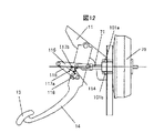
図12は、本発明の更に他の実施の形態の自動車の走行装置における複数個のばねと複数個のクランク軸の組み合わせを含んだブレーキペダルのフットレスト装置を示している。
【0100】
図12に示すフットレスト装置は、ブレーキペダル13,第1レバー14,支持部11,オペレーティングロッド71,シリンダ駆動装置75,ボルト101a,101b,クランクばね114,第1クランク軸115,第2クランク軸116,第1ストッパ117a,117bおよび第2ストッパ118から構成される。
【0101】
第1クランク軸115と第2クランク軸116は、ピンを介して互いの端部が回転可能に結合されている。第2クランク軸116の他の一端はピンを介して第1レバー14に回転可能に結合され、第1クランク軸115の他の一端がピンを介してオペレーティングロッド71に回転可能に結合されている。また、前記2つのクランク軸115,116にはクランクばね114および第1ストッパ117a,117bが結合されている。また、第1レバー14にも第2ストッパ118が結合されている。
【0102】
ここで、ブレーキペダル13に足を置いて力を加えると、第1クランク軸115と第2クランク軸116はピンを中心に幾何学的に角度が閉じる方向に動くために、クランクばね114に力が加わる。このとき、オペレーティングロッド71の軸方向には幾何学的にほとんど力は加わらないために、オペレーティングロッド71の軸方向の移動を規制することができる。ある程度まで閉じると、ストッパ117a,118b同士の接触あるいは第2クランク軸116と第2ストッパ118の接触により、それ以上は閉じなくなる。更に力を加えると、オペレーティングロッド71の軸方向にブレーキペダル13に加わる力の全て加わって普通のブレーキと同様の動作をするようになる。
【0103】
このように、クランクばね114のばね定数を適当に設定することによりフットレスト機能を与えることができる。運転者が限定されている場合は、初めにばね定数を選定しておけば、故障しない限り交換の必要はない。また、ストッパ117a,117b,118は、場合によっては、どちらか1つでも良い。また、クランク軸115,116は、3つ以上にしても良い。
【0104】
図13は、本発明の他の実施の形態を示す自動車の機能ブロック図である。
【0105】
自動車1は、エンジン3,変速機5,変速機5を管理する制御ユニット38,ブレーキ装置6および駆動システム8の全体を管理する制御装置9を有し、それぞれがネットワークを介して通信可能に構成される。
【0106】
また、第1のペダルであるブレーキペダル操作量センサ122,モード選択手段120,第2のペダルであるアクセルペダル操作量センサ123,動力源起動・停止手段121,ブレーキペダル操作量センサ122に基づいて第1の駆動力指令を演算する第1の駆動力指令手段124と、アクセルペダル操作量センサ123に基づく駆動力指令を演算する第2の駆動力指令手段125を備える。
【0107】
自動車1を動かす場合には、まず、動力源(たとえばエンジン3またはモータ4)を起動する必要がある。
【0108】
図14は、この実施の形態において動力源を起動するのに必要な手順のフローチャートをしている。自動車1の制御装置9は、図14に示したフローチャートに従った処理を所定の時間間隔(たとえば100[ms])で実行する。
【0109】
処理ステップ131においては、動力源(たとえばエンジン3またはモータ4)が起動しているか否かを判定する。動力源が起動している場合には、処理ステップ132において現状維持する。
【0110】
自動車1は、ワンペダルモードと通常モードの少なくとも2つのモードで機能する。この2つのモードは、運転者がモード選択手段120を操作していずれか一方を選択する。処理ステップ133は、モード選択手段120においてワンペダルモードが選択されているか否かを判定する。ワンペダルモードが選択されている場合には処理ステップ132において現状維持とする。言い換えれば、動力源が起動していないときにワンペダルモードを選択した場合には、動力源の起動を禁止する。
【0111】
処理ステップ134は、モード選択手段120において通常モードが選択されているか否かを判定する。通常モードが選択されている場合には処理ステップ135において動力源起動・停止手段121が運転者により操作されているか否かを判定する。操作されている場合には処理ステップ136に進み、自動車1に搭載してある動力源、たとえばエンジン3やモータ4を起動する。また、動力源ではないが、走行するのに必要なアクセルペダル操作量センサ123やブレーキペダル操作量センサ122に電源を供給する。
【0112】
動力源起動・停止手段121が操作されていない場合には処理ステップ137に進み、現状維持とする。すなわち、動力源を起動しない。
【0113】
処理ステップ134において通常モードが選択されていない場合は、モード選択手段120が故障していると判断し、処理ステップ138において現状維持とする。すなわち、動力源が起動している場合には起動したままに、停止しているときには停止したままとする。
【0114】
このように、動力源を起動する場合には、モードを必ず通常モードにしてから動力源を起動する。これにより、第1のペダルを操作していないときに動力源を起動して、自動車が発進するのを防ぐことができる。
【0115】
次に、自動車1を停止した場合には、動力源(たとえばエンジン3またはモータ4)を停止する必要がある。図15は、動力源を停止する手順のフローチャートを示している。自動社1の制御装置9は、図15に示したフローチャートに従った処理を所定の時間間隔(たとえば100[ms])で定期的に実行する。
【0116】
処理ステップ141において、動力源が起動しているか否かを判定する。動力源が起動している場合には、処理ステップ142に進む。動力源が起動していない場合には処理150に進んで現状維持とする。
【0117】
処理ステップ142において、モード選択手段120がワンペダルモードか否かを判定する。ワンペダルモードの場合には処理ステップ143へ進む。
【0118】
処理ステップ143では、運転者が動力源起動・停止手段121をオフ操作しているか否かを判定する。オフ操作している場合には、ワンペダルモードから通常モードに変更し、その後、処理ステップ145に進む。
【0119】
処理ステップ142でモード選択手段120が通常モードと判定された場合と、処理ステップ143で動力源起動・停止手段121をオフ操作していない場合には、ワンペダルモードのまま処理ステップ145に進む。
【0120】
処理ステップ145においては、モード選択手段120が通常モードであるか否かを判定する。通常モードである場合には処理ステップ146に進む。
【0121】
処理ステップ146は、運転者が動力源起動・停止手段121をオフ操作しているか否かを判定する。運転者がオフ操作をしている場合には、処理ステップ147において、動力源の停止を行う。オフ操作をしていない場合には、現状維持とする。
【0122】
また、処理ステップ145において通常モードでない場合には、モード選択手段120が故障していると判断し、処理ステップ149において現状維持とする。すなわち、動力源が起動している場合には起動したままに、停止しているときには停止したままとする。
【0123】
このように、動力源を停止する場合には、モードを必ず通常モードにしてから動力源を停止する。これにより、次に動力源を起動するときには必ず通常モードになっており、運転者が動力源起動・停止手段121を操作したときには直ちに動力源を起動することができる効果がある。
【0124】
図16は、この実施の形態において動力源を起動するのに必要な手順のフローチャートの変形例を示している。基本的な考え方は、ワンペダルモードにおいて、第1のペダルを操作しているときに、動力源の起動を行なえるようにしたことである。制御装置9は、図16に示したフローチャートに従った処理を所定の時間間隔で定期的に実行する。
【0125】
処理ステップ151においては、動力源が起動しているか否かを判定する。起動している場合には処理ステップ152に進んで現状維持とする。起動していない場合には処理ステップ153に進み、モード選択手段120がワンペダルモードか否かを判定する。ワンペダルモードである場合には処理ステップ154に進み、動力源起動・停止手段121を運転者がオン操作しているか否かを判定する。オン操作していない場合には処理ステップ152へ進んで現状維持とする。すなわち、動力源は起動しない。
【0126】
一方、オン操作している場合には処理ステップ155に進み、第1のペダルの操作量に基づく第1の駆動力指令手段124の出力が制動力であるか否かを判定する。第1の駆動力指令手段124の出力が制動力でない(駆動力である)場合には、処理ステップ152に進んで現状維持とする。すなわち、動力源は起動しない。
【0127】
また、第1のペダルの操作量に基づく第1の駆動力指令手段124の出力が制動力である場合には、処理ステップ136に進んで動力源を起動する。その他の処理ステップは、図14における処理ステップ134〜138における処理と同様である。
【0128】
このようにすることにより、ワンペダルモードのときにも、第1のペダルを操作して制動力をかけながら動力源を起動できるようにすることで、安全に停止して動力源を起動することができる。
【0129】
【表1】

表1は、本発明の実施の形態における自動車の走行制御装置のワンペダルモードでの走行条件を示している。表1に示す実施の形態は、自動車等が左側通行の国または地域を対象に3つのモードが設定されており、それぞれ最高速度,車間距離,加速度が設定されている。ここで、それぞれのモードにおいて、加速度は直進・左折の場合と右折の場合の2種類が設定されている。このような走行条件を組み込んだシステムとすることにより、右折時に設定加速度を直進・左折より大きな値に遷移させることができる。ここで、モード3の場合は、右折も左折もない高速道路の場合であり、加速度に差を設ける必要はないため同じとなっている。なお、車間距離は、最高速度に対する設定値であり、実際の制御では最高速度以下の速度においては速度にリンクさせて変わるように設定しても良い。また、それぞれの値は、運転者が自由に設定できるようにするが、安全上、車間距離は最高速度の設定値に応じて下限値を持たせ、下限値以下の車間距離に設定することがきないようにするのが望ましい。また、この実施の形態では、直進と左折を同じ設定としているが別でも良い。なお、自動車等が右側通行の国または地域の場合は、表1において右折と左折を入れ替えれば成立する。
【0131】
【表2】
表2は、本発明の実施の形態における自動車の走行制御装置のワンペダルモードでの走行条件の他の例を示している。表2にの示す実施の形態は、自動車等が左側通行の国または地域を対象に3つのモードが設定されており、それぞれ最高速度,車間距離,加速度が設定されている。ここで、それぞれのモードにおいて、加速度は直進の場合と右折・左折の場合の2種類が設定されている。このような走行条件を組み込んだシステムとすることにより、右折・左折時に設定加速度を直進より大きな値に遷移させることができる。しかし、モード3の場合は、表1の場合と同様に、右折も左折もない高速道路の場合であり、加速度に差を設ける必要はないため同じとなっている。なお、車間距離は最高速度に対する設定値であり、実際の制御では最高速度以下の速度においては速度にリンクさせて変わるように設定しても良い。また、表1と同様に、それぞれの値は運転者が自由に設定できるが、安全上、車間距離は最高速度の設定値に応じて下限値を持たせ、下限値以下の車間距離に設定することができないようにするのが望ましい。
【0133】
図17は、本発明の実施の形態の自動車の走行制御装置における加速度を方向指示器により遷移させるための手順のフローチャートを示している。制御装置9は、図17に示したフローチャートに従った処理を所定の時間間隔で定期的に実行する。この実施の形態では、右折時に加速度が右折用加速度に遷移する場合を示している。
【0134】
処理ステップ161で右折方向に方向指示器を入れたと判定した場合は処理ステップ162に進んで予め設定された右折加速度に遷移する。
【0135】
遷移後に処理ステップ163により方向指示器を戻したと判定した場合は処理ステップ164により予め設定された直進用加速度に遷移する。このようにして右折時に加速度を遷移させることができる。
【0136】
図18は、本発明の実施の形態のワンペダルモードを備えた自動車の走行制御装置における時間と速度および時間と制動力のパターンの一例を示している。速度曲線170と制動力曲線172、速度曲線171と制動力曲線173がそれぞれ対応している。図18における速度曲線170は、制御装置9で制動が必要との判断が発生してから目標制止地点に制止するための減速パターンを示している。そのときの制動力曲線172は、制御装置9の演算により路面状態,車両状態から計算された、少なくとも車輪がロックすることのない制動力の値となっている。ところが、制御装置9で判断が発生しても、運転者がこのような制動操作を怠った場合は、制御装置9により運転者の健康を害さない程度の制動力曲線173のような強い制動力を作用させることにより、制動に伴う軽いショックを発生させ運転者に警告を与える。このときの制動力は、車輪がロックすることのないような制動力とする。また、この警告のための制動力は、図19に示す制動力曲線174のように、強弱をつけたパターンでも良い。
【0137】
図20は、本発明の自動車の走行制御装置で制動力を発生させる場合の制御処理手順のフローチャートを示している。この処理は、制御装置9が実行する。
【0138】
まず始めに、処理ステップ181の勾配計測で自車がいる地点の道路の勾配を計測する。処理ステップ182におけるエンジンブレーキ設定は、エンジンによる制動力の設定を行う。処理ステップ183の摩擦ブレーキ設定は、各車輪に付いている摩擦ブレーキによる制動力の指令を設定する。処理ステップ184の油圧設定は、摩擦ブレーキを操作する液圧を保持あるいは解除の設定を行う。
【0139】
図21は、本発明の実施の形態において、図20における勾配演算で燃料タンク内にある燃料残量を計測するフロートを用いて道路の勾配を計測する場合の処理の手順を示すフローチャートである。
【0140】
処理ステップ201において、現在のフロート位置情報を取得する。
【0141】
処理ステップ202は、自車速度が0[m/s]以下か否で自車が停車しているか否かを判定する。自車速度が0[m/s]以下で停車していると判断した場合は、処理ステップ204に進み、停車していないと判断した場合は処理ステップ203に進む。
【0142】
処理ステップ204では、ステップ201で取得した現在のフロート位置情報と前回の周期で取得したフロート位置情報に基づいてフロート位置の変化量を演算する。
【0143】
処理ステップ203では、処理ステップ201で取得したフロート位置情報に基づいて勾配を演算する。
【0144】
処理ステップ205では、処理ステップ204で演算したフロート位置の変化量が予め設定した値x0より大きいか否かを判定する。大きければ処理ステップ206に進み、そうでなければ処理ステップ208に進む。
【0145】
処理ステップ208では、処理ステップ203の勾配演算と同様の処理を行って勾配を演算する。
【0146】
処理ステップ206では、処理ステップ204で演算したフロート位置の変化量が予め設定した値x1より小さいか否かを判定する。予め設定した値x1より小さければ処理ステップ207に進み、そうでなければ処理ステップ209に進む。
【0147】
ガソリンスタンドは水平な位置と仮定し、自車両が給油しているか否かで、ガソリンスタンドにいるか否かを判断する。給油しているときのフロート位置の変化量は勾配が変化するとかきのフロート位置の変化量より小さいので、処理ステップ205および処理ステップ206の判定で、ガソリンスタンドで給油しているか否かを判定している。すなわち、処理ステップ205および処理ステップ206の判定は、自車が水平な位置にいるか否かを判定している。
【0148】
処理ステップ207は、勾配が0[%]のときのフロート位置を設定する。
【0149】
処理ステップ209は、処理ステップ203の勾配演算と同様の処理を行って勾配を演算する。
【0150】
処理ステップ210では、処理ステップ201で取得した現在のフロート位置を前回のフロート位置に設定し、このルーチンを終了する。
【0151】
この実施の形態のように、どの自動車にも付いている燃料残量計を用いて勾配を計測することで、新たに勾配を計測するためのセンサを設けなくても勾配を計測することができ、コストアップを防ぐことができる。
【0152】
図22は、図21における勾配計測処理を説明するための模式図である。図22の(a)は、フロートの水平位置を校正している状態、(b)は勾配を計測している状態である。
【0153】
フロートの水平位置を校正する場合は、ガソリンスタンドは水平な場所であると仮定して、ガソリンスタンドで給油したときのフロート位置を水平の位置と判断する。給油しているときのフロート位置の変化量は、勾配が変化したときのフロート位置の変化量より小さい。そのため、フロート位置の変化量を見れば、自車が給油中か否かを判定して、自車が水平な位置にいるか否かを判断することができる。(b)のように、自車が坂道にいると、燃料タンクは自車に合わせて傾くが、燃料の表面は水平を維持するので、フロートは燃料の表面の位置に合わせて移動する。そこで、水平時のフロート位置と坂道時のフロート位置との偏差から坂道の勾配の大きさを計測することができる。
【0154】
図23および図24は、本発明の実施の形態における主ブレーキ作動を判定するための処理手順のフローチャートである。この処理も制御装置9が実行する。
【0155】
図23は、図20における処理ステップ182のエンジンブレーキ設定のフローチャートである。
【0156】
処理テップ301では、目標制動力Ftarが0[N]より大きいか否かを判定し、目標制動力Ftarが0[N]より大きければ処理ステップ305に進み、そうでなければ処理ステップ302に進む。
【0157】
処理ステップ302では、エンジンブレーキを行うか否かを設定するエンジンブレーキ実行フラグをOFFにして、エンジンブレーキを行わないように設定する。
【0158】
処理ステップ303では、エンジンブレーキ力Fbeの指令値を0[N]に設定する。
【0159】
処理ステップ304では、予め算出された変速機のギヤ位置をそのままのギヤ位置に設定して、このルーチンを終了する。
【0160】
処理ステップ305では、エンジンブレーキ実行フラグをONにして、エンジンブレーキを行うようにする。
【0161】
処理ステップ306では、目標制動力Ftarに基づいて、エンジンブレーキ力Fbeを演算する。
【0162】
ステップ307では、ステップ306で演算したエンジンブレーキ力Fbeに基づいて変速機のギヤ位置を演算し、このルーチンを終了する。
【0163】
こみのように、ギヤ位置を変更してエンジンブレーキを行うことにより、エンジンブレーキでより大きな制動力を得ることができる。
【0164】
図24は、図20における処理ステップ183の摩擦ブレーキ力設定のフローチャートである。
【0165】
処理ステップ401では、目標制動力Ftarが0[N]より大きいか否かを判定し、目標駆動力Ftarが0[N]より大きければ処理ステップ404に進み、そうでなければ処理ステップ402に進む。
【0166】
処理ステップ402では、摩擦ブレーキによる制動力Fbdを0[N]に設定する。
【0167】
処理ステップ403では、摩擦ブレーキへの指令値を0[N]に設定する。
【0168】
処理ステップ404では、目標制動力Ftarとエンジンブレーキ力Fbeに基づいて摩擦ブレーキによる制動力Fbdを(数1)により演算する。
【0169】
Fbd=Ftar−Fbe …(数1)
処理ステップ405では、ブレーキ力を補正するためにブレーキパットの温度を計測する。
【0170】
処理ステップ406では、処理ステップ405で計測したブレーキパットの温度に基づいて摩擦ブレーキへの指令値を設定し、このルーチンを終了する。ブレーキパットの温度に基づいて摩擦ブレーキへの指令値を設定することで、ブレーキパットの温度によらずに安定した制動力を得ることができる。
【0171】
図25は、坂道で減速するときの例を説明する模式図である。図25の(a)は上り坂で減速するときの例であり、(b)は下り坂で減速するときの例である。
【0172】
上り坂では、車重による勾配方向の力の成分が車両を減速させる方向に働くので、小さな制動力で済む。上り坂で制動力を発生させるときには、目標制動力Ftarがエンジンブレーキで発生できる最大の制動力より小さければ、エンジンブレーキだけで制動力Fbdを発生させる。下り坂では、車重による勾配方向の力の成分が車両を加速させる方向に働くので、車両を減速させるには大きな制動力が必要になる。下り坂で制動力を発生させるときには、目標制動力Ftarがエンジンブレーキで発生できる最大の制動力より大きければ、エンジンブレーキで最大の制動力Fbeを発生させ、エンジンブレーキだけでは足りない制動力Fedを摩擦ブレーキで発生させる。エンジンブレーキで出せる制動力の範囲内であれば、エンジンブレーキを使うことにより、摩擦ブレーキによる制動力を抑え、エンジンブレーキ中は燃料を噴射しないので、ブレーキパットの摩耗と燃料消費を抑えることができる。
【0173】
図26は、本発明の実施の形態における図20の処理ステップ184の油圧設定の処理手順のフローチャートである。
【0174】
処理ステップ501では、現在の自車速度が0[m/s]以下か否かで、自車が停車しているか否かを判定する。自車速度が0[m/s]以下で停車していると判断した場合は処理ステップ502に進み、そうでなければ処理ステップ510に進む。
【0175】
処理ステップ502では、前回の自車速度が0[m/s]より大きいか否かで、自車が前回までは走行していたか否かを判定する。前回の自車速度が0[m/s]より大きく自車は走行していたと判断した場合は処理ステップ503に進み、そうでなければ処理ステップ504に進む。
【0176】
処理ステップ503では、勾配の大きさに基づいて停車を維持させるためのブレーキ油圧を設定する。ブレーキ油圧は、勾配の絶対値が大きいほど油圧を大きく設定する。
【0177】
処理ステップ504では、運転モードから駐車モードに移ったか否かを判定し、運転モードから駐車モードに移った場合は処理ステップ508に進み、そうでなければ処理ステップ505に進む。
【0178】
処理ステップ505では、ペダル踏力が駆動力発生踏力以下か否かを判定する。ペダル踏力が駆動力発生踏力以下になった場合は処理ステップ507に進み、そうでなければ処理ステップ506に進む。
【0179】
処理ステップ506では、運転者がペダル踏力を弱めても、処理ステップ503で設定したブレーキ油圧を保持する。
【0180】
処理ステップ507では、保持していたブレーキ油圧を解除する。処理ステップ508でも、処理ステップ507と同様に、保持していたブレーキ油圧を解除する。停車中に保持していたブレーキ油圧を開放することで、ブレーキ油圧を保持するために使っていたエネルギを節約することができる。
【0181】
処理ステップ510では、前述したように勾配に基づいて上り坂と判断した場合は、ブレーキ油圧を解除しても自車両が後ろに下がらない駆動力を発生させるためにスロットル開度を補正する。
【0182】
図27は、図26に示したフローチャートに従った制御処理により上り坂を発進する場合のタイムチャートを示している。
【0183】
自車が停車後に時刻T1で運転者がペダル踏力を弱めてもブレーキ油圧は停車したときの油圧を維持する。時刻T2でシフトレンジをDレンジからPレンジに変更するとブレーキ油圧を解除する。ブレーキ油圧を解除しても、Pレンジのため自動車は動き出さない。時刻T3でPレンジからDレンジに変更すると、自車が後ろに下がらないようにスロットルを開けて駆動力を発生させる。ペダル踏力が駆動力発生踏力より小さくなった時刻T4で、自車は発進するためにスロットルを開いていく。スロットルを開けても駆動力が道路に伝わるまでに遅れがあり、時刻T5で自車は動き出しはじめる。
【0184】
図28は、本発明の実施の形態における図20の処理ステップ184の油圧設定の処理手順を示すフローチャートである。
【0185】
処理ステップ601では、現在の自車速度が0[m/s]以下か否かで自車が停車しているか否かを判定する。自車速度が0[m/s]以下で停車していると判断した場合は処理ステップ602に進み、そうでなければ処理ステップ610に進む。
【0186】
処理ステップ602では、前回の自車速度が0[m/s]より大きいか否かで、自車が前回までは走行していたか否かを判定する。前回の自車速度が0[m/s]より大きく自車は走行していたと判断した場合は処理ステップ603に進み、そうでなければ処理ステップ604に進む。
【0187】
処理ステップ603では、勾配の大きさに基づいて停車を維持させるためのブレーキ油圧を設定する。ブレーキ油圧は、勾配の絶対値が大きいほど油圧を大きく設定する。
【0188】
処理ステップ604では、運転モードに移ったか否かを判定し、運転モードに移った場合は処理ステップ608に進み、そうでなければ処理ステップ605に進む。
【0189】
ステップ605では、ペダル踏力が駆動力発生踏力以下か否かを判定する。ペダル踏力が駆動力発生踏力以下になった場合は、処理ステップ607に進み、そうでなければ処理ステップ606に進む。
【0190】
処理ステップ606では、運転者がペダル踏力を弱めても、処理ステップ603で設定したブレーキ油圧を保持する。
【0191】
処理ステップ607では、保持していたブレーキ油圧を解除する。処理ステップ608も、処理ステップ607と同様に、保持していたブレーキ油圧を解除する。
【0192】
処理ステップ610では、勾配に基づいて上り坂と判断した場合は、ブレーキ油圧を解除しても自車が後ろに下がらない駆動力を発生させるためにスロットル開度を補正する。
【0193】
図29は、図28に示したフローチャートに従った制御処理により上り坂を発進する場合のタイムチャートを示している。
【0194】
自車が停車後に時刻T1で運転者がペダル踏力を弱めてもブレーキ油圧は停車したときの油圧を維持する。時刻T2でシフトレンジをDレンジからNレンジに変更してもブレーキ油圧を保持する。時刻T3でNレンジからDレンジに変更すると、ブレーキ油圧を解除し自車が後ろに下がらないようにスロットルを開けて駆動力を発生させる。ペダル踏力が駆動力発生踏力より小さくなった時刻T4で、自車を発進させるためにスロットルを開いていく。スロットルを開けても駆動力が道路に伝わるまでに遅れがあり、時刻T5で自車は動き出しはじめる。
【0195】
図30は、図26および図28に示したフローチャートに従った制御処理により、シフトレンジを変更しないで上り坂を発進する場合のタイムチャートを示している。
【0196】
自車が停車後に時刻T1で運転者がペダル踏力を弱めても、ブレーキ油圧は停車したときの油圧を維持する。ペダル踏力がフットレスト踏力より小さくなった時刻T4で、自車は発進させるためにスロットルを開いていく。スロットルを開けても駆動力が道路に伝わるまでに遅れがあり、時刻T5で自車は動き出しはじめる。
【0197】
本発明は、前述した各実施の形態の構成に限定されるものではなく、例えば走行モード数および各設定項目は限定されたものではなく、他の設定値を入れても、あるいは加速度以外の設定項目がなくても何ら影響を及ぼすものではない。
【0198】
また、本発明の範囲内であれば、前述した各実施の形態の一部を組み合わせた構成、例えばフットレスト装置ではソレノイド方式と制限止め方式の組み合わせなどとしても良い。また、この実施の形態では、主ブレーキ手段として油圧ブレーキを用いたが、電気ブレーキなどの他のブレーキであっても電気量などを制御することにより同じ効果が得られる。
【0199】
【発明の効果】
本発明によれば、右折や左折時において、ブレーキをかけて減速・停止した後にブレーキペダルを離すことにより右折または左折方向へ直進より大きな加速度で素早く移動(発進・加速)することができ、安全性を高めることができる。
【図面の簡単な説明】
【図1】本発明の一実施の形態を示す自動車の機能ブロック図である。
【図2】ブレーキ操作量(力)に対する制動・駆動力の関係を示す特性図である。
【図3】制御装置が実行する制御処理のフローチャートである。
【図4】駆動力設定スイッチにて設定される目標駆動力特性図である。
【図5】油圧ブレーキシステムをベースにして構成したブレーキ操作機構の一実施の形態を示す模式図である。
【図6】追従モードからマニュアルモードへの切り換え手法を示す特性図である。
【図7】表示内容の一例を示す図である。
【図8】本発明の他の実施の形態の自動車の走行制御装置における機械的制限止め機構を含んだブレーキペダルのフットレスト装置を示す側面図である。
【図9】本発明の図8に示す実施の形態におけるフットレスト装置の変形例を示す側面図である。
【図10】本発明の図8に示した実施の形態におけるフットレスト装置の変形例を示す側面図である。
【図11】本発明の他の実施の形態の自動車の走行制御装置におけるソレノイド機構を含んだブレーキペダルのフットレスト装置の側面図である。
【図12】本発明の他の実施の形態の自動車の走行制御装置におけるばねとクランク軸の組み合わせを含んだブレーキペダルのフットレスト装置の側面図である。
【図13】本発明の他の実施の形態を示す自動車の機能ブロック図である。
【図14】本発明の他の実施の形態の動力源を起動するための手順のフローチャートである。
【図15】本発明の他の実施の形態の動力源を停止するための手順のフローチャートである。
【図16】本発明の図14に示した手順の変形例を示すフローチャートである。
【図17】本発明の実施の形態の自動車の走行制御装置における加速度を方向指示器により遷移させるための手順のフローチャートである。
【図18】本発明の実施の形態のワンペダルモードを備えた自動車の走行制御装置における時間と速度および時間と制動力のパターンの一例を示している。
【図19】本発明の実施の形態のワンペダルモードを備えた自動車の走行制御装置における時間と速度および時間と制動力のパターンの他の例を示している。
【図20】本発明の自動車の走行制御装置で制動力を発生させる場合の制御手順のフローチャートである。
【図21】本発明の実施の形態における道路の勾配を計測する手順のフローチャートである。
【図22】勾配計測の模式図である。
【図23】本発明の実施の形態におけるエンジンブレーキ設定の手順のフローチャートである。
【図24】本発明の実施の形態における摩擦ブレーキ力設定の手順のフローチャートである。
【図25】坂道で減速するときの模式図である。
【図26】本発明の実施の形態における油圧設定の手順のフローチャートである。
【図27】上り坂を発進する場合のタイムチャートである。
【図28】本発明の実施の形態における油圧設定の手順のフローチャートである。
【図29】上り坂を発進する場合のタイムチャートである。
【図30】上り坂を発進する場合のタイムチャートである。
【符号の説明】
9…制御装置、13…ブレーキペダル、14…第1レバー、15…回転軸、16…第2レバー、17…部材、18…爪、19…第1ペダル反力機構、20…第2ペダル反力機構、21…ブレーキペダル操作量センサ。[0001]
BACKGROUND OF THE INVENTION
The present invention relates to an automobile travel control apparatus and method, and an automobile using the same, and particularly relates to inter-vehicle distance control auto-cruise including slow acceleration / deceleration traveling such as in a traffic jam.
[0002]
[Prior art]
Development of technology for detecting the distance between the host vehicle and the vehicle ahead (including obstacles) using a radar and automatically controlling the engine, motor, transmission, brake, etc. so that a safe inter-vehicle distance is achieved. An example is inter-vehicle distance control auto-cruise (hereinafter referred to as “ACC”: Adaptive Cruise Control) that includes slow acceleration / deceleration driving in a traffic jam.
[0003]
In order to ensure higher safety in such a case, a system is considered in which automatic control is executed only for start and acceleration, and deceleration and stop are performed by the driver's intention.
[0004]
As an example, a system that uses a current hydraulic brake system to perform deceleration / stop and start / acceleration by operating only the brake pedal is considered.
[0005]
For example, Japanese Patent Application Laid-Open No. 4-38600 discloses a vehicle that stops and starts a vehicle by one-pedal traveling only with a brake operation when a slow acceleration / deceleration traveling mode such as a traffic jam is set. In other words, when there is no braking operation, the driving force is controlled so that the vehicle traveling speed becomes the target traveling speed, and when there is a braking operation, the driving force is controlled not to be applied in the traveling direction. It is.
[0006]
[Problems to be solved by the invention]
According to the above-described prior art, in order to realize the stop / start of the vehicle with only one brake operation using the existing brake operation mechanism, the vehicle is decelerated / stopped by operating the brake pedal, and the brake pedal is released. It could only be used in an ON-OFF manner, such as starting and accelerating.
[0007]
When turning right or left, it is desirable from the viewpoint of safety that movement in the right or left turn direction can be realized quickly after braking and decelerating and stopping.
[0019]
[Means for Solving the Problems]
The present invention relates to a right turn or a right turn while driving in the one-pedal mode in a country or region where the vehicle's traffic zone on the road is defined as the left side of the traveling direction, or the vehicle's traffic zone is the right side of the traveling direction. In the case of a left turn or a left turn while driving in the one-pedal mode in the specified country or region, the preset acceleration is set in advance from the case where the set acceleration is straight.Bigger than straight aheadConfigure to transition to acceleration.
[0020]
Since a vehicle equipped with the travel control device of the present invention can be applied to a general road, a situation where a right turn or a left turn at an intersection or the like is created. In that case, in a left-handed country like Japan, when making a right turn, it is often necessary to make a quick right turn while ensuring safety by keeping the distance between cars traveling in the opposite lane. In such a case, when turning right as in the present invention, it was previously set for right turn.Bigger than straight aheadYou can make a right turn more safely if you make the transition to acceleration. On the other hand, in the right-hand traffic country or region, the left turn is set in advance when turning left.Bigger than straight aheadIt is safer to turn to the left if the transition is made to acceleration.
[0021]
In the present invention, in the case of turning right or turning right while driving in the one-pedal mode, turning left or turning left is set in advance from the case where the set acceleration is straight.Bigger than straight aheadConfigure to transition to acceleration. With this setting, when making a left turn at an intersection without a signal in a country or region where the vehicle's traffic zone is defined as the left side of the direction of travel, for example, when turning left at a temporary stop, It is often necessary to make a quick left turn while confirming. In such a case, when turning left as in the present invention, it was set for right or left turn in advance.Bigger than straight aheadIt is safer to turn to the left if the transition is made to acceleration. On the other hand, in right-passing countries or regions, on the contrary, when turning right, it was set in advance for right or left turn.Bigger than straight aheadIt is safer to make a right turn if you change to acceleration.
[0022]
Preferably, when the set acceleration changes,Turn right or leftWhen the direction indicator is turned on in the direction of travel. Thereby, the acceleration can be changed only at that time by a simple operation of the driver.
[0031]
DETAILED DESCRIPTION OF THE INVENTION
FIG. 1 is a functional block diagram of an automobile showing an embodiment of the present invention.
[0032]
The
[0033]
First, the
[0034]
When the second lever 16 and the claw 18 of the
[0035]
That is, when the driver (not shown) operates the
[0036]
Thereafter, when the driver operates the
[0037]
Further, a brake pedal
[0038]
Here, although an example using the
[0039]
Next, the configuration of the
[0040]
The
[0041]
Here, an example of a gasoline engine is shown, but other engines such as a diesel engine and a gas turbine can also be applied. As for gasoline engines, port fuel injection engines that inject fuel into the intake pipe, in-cylinder fuel injection engines that inject fuel directly into the cylinder, and mirror engines that improve combustion efficiency through electronic control of intake and exhaust valves are put into practical use. There is no problem to apply any engine. However, it goes without saying that an engine system that achieves both a reduction in fuel consumption and a reduction in exhaust gas is most suitable from the viewpoint of global environmental problems.
[0042]
The
[0043]
At high speed, the output torque of the
[0044]
Similarly, at medium speed and low speed, the output torque of the
[0045]
In general, these dog clutches are known to have no slip loss at the time of engagement and high transmission efficiency. In particular, when the gears are switched between the medium speed and the low speed, the torque of the
[0046]
Further, in the case of traveling only by the
[0047]
All the clutches are operated by the
[0048]
In this embodiment, a hydraulic actuator is used to operate the clutch. However, an electric actuator such as an ultrasonic motor, a DC motor, or an AC motor may be used.
[0049]
Furthermore, the
[0050]
The brake devices 6a to 6d include
[0051]
On the other hand, the brake clutch 39 provided in the
[0052]
Next, the control device 9 that controls the
[0053]
The control device 9 has a control unit (not shown) for controlling the
[0054]
The control device 9 also includes a signal β of the brake pedal
[0055]
Based on these input signals, the control device 9 controls the
[0056]
Next, the function of the
[0057]
An object of the present invention is to realize start and stop of a vehicle without a driver taking his / her foot off the
[0058]
First, a footrest function range (A range in FIG. 2) was provided as one of the functions of the brake operation amount. That is, the reaction force of the second pedal
[0059]
Thereafter, for example, when slow deceleration (B range in FIG. 2) is required, the driver steps on the
[0060]
Further, as shown in FIG. 1, in a vehicle (HEV: hybrid vehicle) equipped with a
[0061]
Further, when the operation amount of the
[0062]
The above braking force is a braking force increasing line passing through the line F (when the determination result of processing
[0063]
Next, a case where Δβ becomes smaller than −k1 in the determination of the
[0064]
In this case, the process proceeds to process
[0065]
In the range A in FIG. 2, the target driving force Ac for acceleration is set by the brake operation amount β, the vehicle speed No, the target driving force Ttar set by the driving
[0066]
Further, the inclination of the lines F and G can be arbitrarily determined by the driver, and the acceleration / deceleration feeling intended by the driver can be realized. The maximum braking force should not be changed for safety reasons.
[0067]
FIG. 4 shows a target driving force (acceleration) characteristic set by the driving
[0068]
These driving force characteristics are also set by changes in the road environment obtained from navigation, infrastructure information such as VICS (Vehicle Information and Communication System), HEO (long elliptical orbit satellite) system, such as highways, mountain roads, and urban areas. Making it possible.
[0069]
FIG. 5 shows an embodiment of a
[0070]
An operating rod 71 (
[0071]
The
[0072]
When the driver steps on the
[0073]
The operating
[0074]
Further, in the brake operation range A shown in FIG. 2, a
[0075]
The reaction force of the third pedal
[0076]
That is, similarly to the embodiment shown in FIG. 1, in this embodiment, the vehicle can be started and stopped without the driver releasing his / her foot from the
[0077]
FIG. 6 shows a switching method from the follow mode to the manual mode. In the present invention, the tracking mode and the manual mode can be switched by setting the travel
[0078]
In general, when a person performs one action continuously, and performs another action after getting used to the action, it takes time to get used to this another action. Therefore, if the driver suddenly shifts to the manual mode after driving for a long time in the follow-up mode, the driver cannot complete the driving sensation in the previous driving mode, and there is a possibility that an erroneous operation may be executed.
[0079]
Therefore, as shown in FIG. 6, the time (Toff) from when the tracking mode switch is turned off to when the tracking mode is actually turned off is changed according to the length of the tracking mode ON time (Ton). To do. That is, when the follow-up mode time is long, Toff is set to be long, and the driving support in the follow-up mode is continued during the period set to Toff. Further, when switching from manual mode to follow-up mode, switching to safe driving control is performed, so the time from when the manual mode switch is turned off to when it is actually turned off may be shorter than Toff (including time zero). ).
[0080]
By doing so, the driver's erroneous operation when shifting to the manual mode after driving for a long time in the follow-up mode is reduced, and safe mode switching can be realized.
[0081]
FIG. 7 is an example of display contents on the display unit. When there are a plurality of driving modes such as the following mode and the manual mode as in the present invention, the driver is uneasy if he / she cannot recognize what kind of driving is currently being executed or whether it is not really malfunctioning. There is a possibility.
[0082]
Therefore, it is desirable to provide a
[0083]
The display of the
[0084]
Next, the driver should want to know what the vehicle is currently driving. For example, in the display of the
[0085]
It is also important to display whether or not driver assistance is being performed during the brake operation and to inform the driver that the vehicle is currently in a dangerous driving state. Furthermore, when the control system fails, it is desirable to display the
[0086]
The display is necessary for communication between the driver and the machine (vehicle), and is one of important means for the driver to travel safely and safely.
[0087]
As described above, the embodiments of the present invention have been described using the inter-vehicle distance control auto-cruise that detects the vehicle ahead or an obstacle and keeps the distance from the front object safe. However, the system that achieves braking and driving with one pedal according to the present invention can be applied to vehicle speed constant control (auto cruise) that has been put into practical use. In other words, the difference is whether or not a forward object is detected. In vehicle speed constant control that does not detect a forward object, settings (target acceleration and target speed) and operations (depending on the brake operation mechanism 2) according to the behavior of the forward object. The driver only needs to execute (braking force setting).
[0088]
FIG. 8 shows a footrest device for a brake pedal including a mechanical limit stop mechanism in a traveling control device for an automobile according to another embodiment of the present invention.
[0089]
The footrest device shown in FIG. 8 includes a
[0090]
When the footrest device is operated, the
[0091]
FIGS. 9 and 10 show a modification of the footrest device for the brake pedal including the mechanical limit stop mechanism in the automobile travel control device of this embodiment. In this modification, a shutter mechanism using a
[0092]
In order to operate the footrest function, as shown in FIG. 9, the
[0093]
A method for returning to the normal brake pedal form from the footrest function state as shown in FIG. 10 will be described below.
[0094]
First, the
[0095]
FIG. 11 shows a footrest device for a brake pedal including a solenoid mechanism in an automobile travel control device according to still another embodiment of the present invention.
[0096]
The footrest device shown in FIG. 11 includes a
[0097]
The
[0098]
Here, to operate the footrest function, the solenoid is energized. As a result, a magnetic attraction force is generated and the
[0099]
FIG. 12 shows a footrest device for a brake pedal including a combination of a plurality of springs and a plurality of crankshafts in an automobile traveling device according to still another embodiment of the present invention.
[0100]
The footrest device shown in FIG. 12 includes a
[0101]
The
[0102]
Here, when a force is applied with the foot placed on the
[0103]
Thus, the footrest function can be provided by appropriately setting the spring constant of the
[0104]
FIG. 13 is a functional block diagram of an automobile showing another embodiment of the present invention.
[0105]
The
[0106]
Further, based on a brake pedal
[0107]
When the
[0108]
FIG. 14 is a flowchart of a procedure necessary for starting the power source in this embodiment. The control device 9 of the
[0109]
In
[0110]
The
[0111]
The
[0112]
If the power source starting / stopping means 121 is not operated, the process proceeds to processing
[0113]
If the normal mode is not selected in the
[0114]
Thus, when starting the power source, the power source is started after the mode is always set to the normal mode. Thus, it is possible to prevent the automobile from starting by starting the power source when the first pedal is not operated.
[0115]
Next, when the
[0116]
In
[0117]
In
[0118]
In
[0119]
When the
[0120]
In
[0121]
Processing
[0122]
If it is not the normal mode in
[0123]
Thus, when stopping the power source, the power source is stopped after the mode is always set to the normal mode. Thus, the next time the power source is started, the normal mode is always set. When the driver operates the power source start / stop means 121, the power source can be started immediately.
[0124]
FIG. 16 shows a modification of the flowchart of the procedure necessary to start the power source in this embodiment. The basic idea is that the power source can be activated when operating the first pedal in the one-pedal mode. The control device 9 periodically executes processing according to the flowchart shown in FIG. 16 at predetermined time intervals.
[0125]
In
[0126]
On the other hand, when the on-operation is performed, the process proceeds to processing
[0127]
When the output of the first driving force command means 124 based on the operation amount of the first pedal is a braking force, the process proceeds to processing
[0128]
In this way, even in the one-pedal mode, the power source can be started while operating the first pedal while applying a braking force, so that the power source can be safely stopped and started. Can do.
[0129]
[Table 1]
Table 1 shows traveling conditions in the one-pedal mode of the traveling control device for an automobile in the embodiment of the present invention. In the embodiment shown in Table 1, three modes are set for a country or region in which a car or the like passes on the left side, and a maximum speed, an inter-vehicle distance, and an acceleration are set, respectively. Here, in each mode, two types of acceleration are set for straight / left turn and for right turn. By adopting a system that incorporates such driving conditions, the set acceleration can be set when turning right.A value larger than straight / left turnTransition can be made. Here, the case of
[0131]
[Table 2]
Table 2 shows another example of the traveling condition in the one-pedal mode of the traveling control device for an automobile in the embodiment of the present invention. In the embodiment shown in Table 2, three modes are set for a country or region in which a car or the like passes on the left side, and a maximum speed, an inter-vehicle distance, and an acceleration are set, respectively. Here, in each mode, two types of acceleration are set: straight acceleration and right / left turn. By adopting a system that incorporates such driving conditions, the set acceleration can be set when turning right or left.To a value larger than straightTransition can be made. However, in the case of
[0133]
FIG. 17 shows a flowchart of a procedure for causing the direction indicator to transition the acceleration in the automobile travel control apparatus according to the embodiment of the present invention. The control device 9 periodically executes processing according to the flowchart shown in FIG. 17 at predetermined time intervals. In this embodiment, the case where the acceleration changes to the acceleration for right turn at the time of right turn is shown.
[0134]
If it is determined in
[0135]
If it is determined that the direction indicator has been returned in
[0136]
FIG. 18 shows an example of a pattern of time, speed, time, and braking force in the travel control device for an automobile having the one pedal mode according to the embodiment of the present invention. The
[0137]
FIG. 20 shows a flowchart of a control processing procedure when a braking force is generated in the automobile travel control apparatus of the present invention. This process is executed by the control device 9.
[0138]
First, the slope of the road where the host vehicle is located is measured by the slope measurement in
[0139]
FIG. 21 is a flowchart showing a processing procedure when the road gradient is measured using the float that measures the remaining amount of fuel in the fuel tank by the gradient calculation in FIG. 20 in the embodiment of the present invention.
[0140]
In
[0141]
Processing
[0142]
In
[0143]
In
[0144]
In processing step 205, it is determined whether or not the amount of change in the float position calculated in processing
[0145]
In the
[0146]
In
[0147]
The gas station is assumed to be in a horizontal position, and whether or not the vehicle is at the gas station is determined based on whether or not the vehicle is refueling. Since the amount of change in the float position when refueling is smaller than the amount of change in the float position of oysters when the gradient changes, it is determined in processing step 205 and
[0148]
Processing
[0149]
The
[0150]
In
[0151]
As in this embodiment, by measuring the gradient using a fuel fuel gauge attached to any vehicle, the gradient can be measured without providing a new sensor for measuring the gradient. , Can prevent cost increase.
[0152]
FIG. 22 is a schematic diagram for explaining the gradient measurement process in FIG. 22A shows a state where the horizontal position of the float is calibrated, and FIG. 22B shows a state where the gradient is being measured.
[0153]
When calibrating the horizontal position of the float, it is assumed that the gas station is a horizontal place, and the float position when refueling at the gas station is determined as the horizontal position. The amount of change in the float position when refueling is smaller than the amount of change in the float position when the gradient changes. Therefore, by looking at the amount of change in the float position, it can be determined whether or not the own vehicle is being refueled and whether or not the own vehicle is in a horizontal position. As shown in (b), when the own vehicle is on a slope, the fuel tank is tilted in accordance with the own vehicle, but the surface of the fuel is kept horizontal, so that the float moves in accordance with the position of the surface of the fuel. Therefore, the slope gradient can be measured from the deviation between the horizontal float position and the slope float position.
[0154]
23 and 24 are flowcharts of processing procedures for determining the main brake operation in the embodiment of the present invention. This process is also executed by the control device 9.
[0155]
FIG. 23 is a flowchart of engine brake setting in
[0156]
In
[0157]
In
[0158]
In
[0159]
In
[0160]
In
[0161]
In processing step 306, the engine braking force Fbe is calculated based on the target braking force Ftar.
[0162]
In
[0163]
As described above, when the engine is braked by changing the gear position, a larger braking force can be obtained by the engine brake.
[0164]
FIG. 24 is a flowchart of friction brake force setting in
[0165]
In
[0166]
In
[0167]
In
[0168]
In
[0169]
Fbd = Ftar−Fbe (Equation 1)
In
[0170]
In
[0171]
FIG. 25 is a schematic diagram for explaining an example when decelerating on a slope. (A) of FIG. 25 is an example when decelerating on an uphill, and (b) is an example when decelerating on a downhill.
[0172]
On the uphill, the force component in the gradient direction due to the vehicle weight acts in the direction of decelerating the vehicle, so a small braking force is sufficient. When the braking force is generated uphill, if the target braking force Ftar is smaller than the maximum braking force that can be generated by the engine brake, the braking force Fbd is generated only by the engine brake. On the downhill, the force component in the gradient direction due to the vehicle weight acts in the direction of accelerating the vehicle, so a large braking force is required to decelerate the vehicle. When the braking force is generated on the downhill, if the target braking force Ftar is larger than the maximum braking force that can be generated by the engine brake, the maximum braking force Fbe is generated by the engine brake, and the braking force Fed that is not sufficient only by the engine brake is generated. Generate with friction brake. If it is within the range of braking force that can be produced by the engine brake, the braking force by the friction brake is suppressed by using the engine brake, and fuel is not injected during the engine braking, so that wear of the brake pad and fuel consumption can be suppressed. .
[0173]
FIG. 26 is a flowchart of a processing procedure for hydraulic pressure setting in
[0174]
In
[0175]
In
[0176]
In
[0177]
In
[0178]
In
[0179]
In the
[0180]
In
[0181]
In
[0182]
FIG. 27 shows a time chart in the case of starting uphill by the control process according to the flowchart shown in FIG.
[0183]
Even when the driver weakens the pedal depression force at time T1 after the own vehicle stops, the brake hydraulic pressure maintains the hydraulic pressure when the vehicle stops. When the shift range is changed from the D range to the P range at time T2, the brake hydraulic pressure is released. Even if the brake oil pressure is released, the car does not start because of the P range. When the range is changed from the P range to the D range at time T3, the throttle is opened so that the driving force is generated so that the host vehicle does not fall backward. At time T4 when the pedal depression force becomes smaller than the driving force generation depression force, the host vehicle opens the throttle to start. Even if the throttle is opened, there is a delay until the driving force is transmitted to the road, and the vehicle starts to move at time T5.
[0184]
FIG. 28 is a flowchart showing a processing procedure for hydraulic pressure setting in
[0185]
In
[0186]
In
[0187]
In
[0188]
In
[0189]
In
[0190]
In process step 606, even if the driver weakens the pedal effort, the brake hydraulic pressure set in
[0191]
In
[0192]
In
[0193]
FIG. 29 shows a time chart in the case of starting uphill by the control process according to the flowchart shown in FIG.
[0194]
Even when the driver weakens the pedal depression force at time T1 after the own vehicle stops, the brake hydraulic pressure maintains the hydraulic pressure when the vehicle stops. Even if the shift range is changed from the D range to the N range at time T2, the brake hydraulic pressure is maintained. When the N range is changed to the D range at time T3, the brake hydraulic pressure is released, and the throttle is opened to generate the driving force so that the vehicle does not fall backward. At time T4 when the pedal depression force becomes smaller than the driving force generation depression force, the throttle is opened in order to start the vehicle. Even if the throttle is opened, there is a delay until the driving force is transmitted to the road, and the vehicle starts to move at time T5.
[0195]
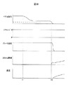
FIG. 30 shows a time chart when starting uphill without changing the shift range by the control processing according to the flowcharts shown in FIGS. 26 and 28.
[0196]
Even if the driver weakens the pedal depression force at time T1 after the own vehicle stops, the brake hydraulic pressure maintains the hydraulic pressure when the vehicle stops. At time T4 when the pedal depression force becomes smaller than the footrest depression force, the vehicle opens the throttle to start. Even if the throttle is opened, there is a delay until the driving force is transmitted to the road, and the vehicle starts to move at time T5.
[0197]
The present invention is not limited to the configuration of each of the embodiments described above. For example, the number of driving modes and each setting item are not limited, and other setting values may be entered or settings other than acceleration may be set. The absence of an item has no effect.
[0198]
Further, within the scope of the present invention, a configuration in which a part of each of the above-described embodiments is combined, for example, a combination of a solenoid system and a limit stop system may be used in a footrest device. Further, in this embodiment, the hydraulic brake is used as the main brake means, but the same effect can be obtained by controlling the amount of electricity even with other brakes such as an electric brake.
[0199]
【The invention's effect】
According to the present invention,When turning right or left, you can brake (decelerate and stop), release the brake pedal, and then move quickly (start / accelerate) in a right turn or left turn direction with a greater acceleration than starting straight, increasing safety.be able to.
[Brief description of the drawings]
FIG. 1 is a functional block diagram of an automobile showing an embodiment of the present invention.
FIG. 2 is a characteristic diagram showing the relationship of braking / driving force to braking operation amount (force).
FIG. 3 is a flowchart of control processing executed by the control device.
FIG. 4 is a target driving force characteristic diagram set by a driving force setting switch.
FIG. 5 is a schematic view showing an embodiment of a brake operation mechanism configured based on a hydraulic brake system.
FIG. 6 is a characteristic diagram showing a method for switching from the follow-up mode to the manual mode.
FIG. 7 is a diagram illustrating an example of display content.
FIG. 8 is a side view showing a footrest device for a brake pedal including a mechanical limit stop mechanism in an automobile travel control device according to another embodiment of the present invention.
FIG. 9 is a side view showing a modification of the footrest device in the embodiment shown in FIG. 8 of the present invention.
FIG. 10 is a side view showing a modification of the footrest device in the embodiment shown in FIG. 8 of the present invention.
FIG. 11 is a side view of a footrest device for a brake pedal including a solenoid mechanism in a vehicle travel control device according to another embodiment of the present invention.
FIG. 12 is a side view of a footrest device for a brake pedal including a combination of a spring and a crankshaft in a vehicle travel control device according to another embodiment of the present invention.
FIG. 13 is a functional block diagram of an automobile showing another embodiment of the present invention.
FIG. 14 is a flowchart of a procedure for starting a power source according to another embodiment of the present invention.
FIG. 15 is a flowchart of a procedure for stopping a power source according to another embodiment of the present invention.
16 is a flowchart showing a modification of the procedure shown in FIG. 14 of the present invention.
FIG. 17 is a flowchart of a procedure for causing the direction indicator to transition acceleration in the automobile travel control apparatus according to the embodiment of the present invention.
FIG. 18 shows an example of a pattern of time, speed, time, and braking force in the vehicle travel control apparatus having the one-pedal mode according to the embodiment of the present invention.
FIG. 19 shows another example of a pattern of time, speed, time, and braking force in the vehicle travel control apparatus having the one-pedal mode according to the embodiment of the present invention.
FIG. 20 is a flowchart of a control procedure in the case where a braking force is generated in the vehicle travel control apparatus of the present invention.
FIG. 21 is a flowchart of a procedure for measuring a road gradient according to the embodiment of the present invention.
FIG. 22 is a schematic diagram of gradient measurement.
FIG. 23 is a flowchart of an engine brake setting procedure in the embodiment of the present invention.
FIG. 24 is a flowchart of a friction brake force setting procedure in the embodiment of the present invention.
FIG. 25 is a schematic diagram when decelerating on a slope.
FIG. 26 is a flowchart of a hydraulic pressure setting procedure according to the embodiment of the present invention.
FIG. 27 is a time chart when starting uphill.
FIG. 28 is a flowchart of a hydraulic pressure setting procedure according to the embodiment of the present invention.
FIG. 29 is a time chart when starting uphill.
FIG. 30 is a time chart when starting uphill.
[Explanation of symbols]
DESCRIPTION OF SYMBOLS 9 ... Control apparatus, 13 ... Brake pedal, 14 ... 1st lever, 15 ... Rotating shaft, 16 ... 2nd lever, 17 ... Member, 18 ... Nail | claw, 19 ... 1st pedal reaction force mechanism, 20 ... 2nd pedal reaction Force mechanism, 21 ... Brake pedal operation amount sensor.
Claims (3)
前記制御装置は、道路上における自動車の通行帯が進行方向の左側と定められている国または地域における前記ワンペダルモードで走行中の一般道路での右折または右転回の場合、または自動車の通行帯が進行方向の右側と定められている国または地域における前記ワンペダルモードで走行中の一般道路での左折または左転回の場合は、設定加速度が直進の場合から、予め設定された直進より大きな加速度に遷移することを特徴とする自動車の走行制御装置。A first pedal, a second pedal, and a control device that executes a one-pedal mode control that controls both the braking force and the driving force of the vehicle in accordance with the operation amount or the operation force of the first pedal. In the driving control device of an automobile,
In the case of a right turn or a right turn on a general road running in the one-pedal mode in a country or region where the vehicle's traffic zone on the road is defined as the left side of the traveling direction, or the vehicle's traffic zone When turning left or turning left on a general road that is running in the one-pedal mode in a country or region where is defined as the right side of the direction of travel, the acceleration is greater than the preset straight travel from the case where the set acceleration is straight A travel control device for an automobile characterized by transitioning to
Priority Applications (1)
| Application Number | Priority Date | Filing Date | Title |
|---|---|---|---|
| JP2003156618A JP4283039B2 (en) | 1999-07-01 | 2003-06-02 | Automobile traveling control device and automobile |
Applications Claiming Priority (2)
| Application Number | Priority Date | Filing Date | Title |
|---|---|---|---|
| JP18724799 | 1999-07-01 | ||
| JP2003156618A JP4283039B2 (en) | 1999-07-01 | 2003-06-02 | Automobile traveling control device and automobile |
Related Parent Applications (1)
| Application Number | Title | Priority Date | Filing Date |
|---|---|---|---|
| JP2000056050A Division JP2001071794A (en) | 1999-07-01 | 2000-02-28 | Automobile running control device and automobile |
Publications (3)
| Publication Number | Publication Date |
|---|---|
| JP2004042890A JP2004042890A (en) | 2004-02-12 |
| JP2004042890A5 JP2004042890A5 (en) | 2006-10-05 |
| JP4283039B2 true JP4283039B2 (en) | 2009-06-24 |
Family
ID=31719100
Family Applications (1)
| Application Number | Title | Priority Date | Filing Date |
|---|---|---|---|
| JP2003156618A Expired - Lifetime JP4283039B2 (en) | 1999-07-01 | 2003-06-02 | Automobile traveling control device and automobile |
Country Status (1)
| Country | Link |
|---|---|
| JP (1) | JP4283039B2 (en) |
Families Citing this family (14)
| Publication number | Priority date | Publication date | Assignee | Title |
|---|---|---|---|---|
| JP4969905B2 (en) * | 2006-05-09 | 2012-07-04 | 本田技研工業株式会社 | Mode switching device for vehicle |
| JP4765766B2 (en) | 2006-05-23 | 2011-09-07 | 日産自動車株式会社 | VEHICLE DRIVE OPERATION ASSISTANCE DEVICE AND VEHICLE WITH VEHICLE DRIVE OPERATION ASSISTANCE DEVICE |
| JP4985110B2 (en) * | 2007-06-01 | 2012-07-25 | 住友電気工業株式会社 | Vehicle driving support system, driving support device, vehicle, and vehicle driving support method |
| JP4725565B2 (en) * | 2007-09-11 | 2011-07-13 | 住友電気工業株式会社 | Information providing apparatus, information providing system, and information providing method |
| JP4715826B2 (en) * | 2007-09-28 | 2011-07-06 | 住友電気工業株式会社 | Vehicle driving support system, driving support device, vehicle, and vehicle driving support method |
| US9216740B2 (en) * | 2010-06-15 | 2015-12-22 | Toyota Jidosha Kabushiki Kaisha | Driving support system |
| JP5639611B2 (en) * | 2012-03-21 | 2014-12-10 | 富士重工業株式会社 | Vehicle control device |
| JP6070045B2 (en) * | 2012-10-16 | 2017-02-01 | 日産自動車株式会社 | Vehicle travel control device |
| US10640113B2 (en) | 2013-08-20 | 2020-05-05 | Ge Global Sourcing Llc | System and method for controlling a vehicle |
| EP3092145A4 (en) * | 2014-01-10 | 2017-09-13 | General Electric Company | Control system and method for a vehicle |
| JP2017001635A (en) | 2015-06-16 | 2017-01-05 | ローベルト ボッシュ ゲゼルシャフト ミット ベシュレンクテル ハフツング | Vehicle body behavior control device and vehicle body behavior control method |
| JP2017001636A (en) | 2015-06-16 | 2017-01-05 | ローベルト ボッシュ ゲゼルシャフト ミット ベシュレンクテル ハフツング | Vehicle body behavior control device and vehicle body behavior control method |
| DE102017218660A1 (en) * | 2017-10-19 | 2019-04-25 | Robert Bosch Gmbh | Automatic braking device for a vehicle and method for automatically braking a vehicle |
| JP2020026269A (en) * | 2019-08-17 | 2020-02-20 | 典政 佐々木 | Pedal as control device of automobile |
-
2003
- 2003-06-02 JP JP2003156618A patent/JP4283039B2/en not_active Expired - Lifetime
Also Published As
| Publication number | Publication date |
|---|---|
| JP2004042890A (en) | 2004-02-12 |
Similar Documents
| Publication | Publication Date | Title |
|---|---|---|
| US7209821B2 (en) | Apparatus for controlling run of a car, and car using the apparatus | |
| CN106467107B (en) | Method for controlling vehicle | |
| US10611376B2 (en) | Methods and system for decelerating a vehicle | |
| JP4283039B2 (en) | Automobile traveling control device and automobile | |
| US7502679B2 (en) | Deceleration control apparatus and method for a vehicle | |
| RU2561658C1 (en) | Vehicle control device | |
| US10960882B2 (en) | Method and system for creep torque control | |
| US9199645B2 (en) | Vehicle control apparatus | |
| CN103687770B (en) | Drive assist system | |
| US20060108868A1 (en) | Braking force retaining unit | |
| EP3575130A1 (en) | Vehicle control system and method of controlling the same, and braking device | |
| JP2001354126A (en) | Vehicular brake device | |
| US20130066508A1 (en) | Hybrid vehicle accelerator pedal depressing force control device | |
| JP2012214181A (en) | Vehicle control system | |
| JP2000351340A (en) | Vehicle with brake force holding device | |
| US6622078B1 (en) | Vehicle running control device and vehicle | |
| JP2006213287A (en) | Brake controlling device of vehicle | |
| WO2009022968A1 (en) | Cruise control system and method for a vehicle | |
| JP2001071794A (en) | Automobile running control device and automobile | |
| CN112776806B (en) | Vehicle and control method thereof | |
| CN114802188A (en) | Control device for hybrid vehicle | |
| JP4462046B2 (en) | Brake control device for vehicle | |
| JP3783550B2 (en) | Vehicle travel control device | |
| WO2019111397A1 (en) | Control method and control device for vehicle | |
| JP2015000578A (en) | Vehicular travel control device |
Legal Events
| Date | Code | Title | Description |
|---|---|---|---|
| A521 | Written amendment |
Free format text: JAPANESE INTERMEDIATE CODE: A523 Effective date: 20060822 |
|
| A621 | Written request for application examination |
Free format text: JAPANESE INTERMEDIATE CODE: A621 Effective date: 20060822 |
|
| A131 | Notification of reasons for refusal |
Free format text: JAPANESE INTERMEDIATE CODE: A131 Effective date: 20080902 |
|
| A521 | Written amendment |
Free format text: JAPANESE INTERMEDIATE CODE: A523 Effective date: 20081023 |
|
| TRDD | Decision of grant or rejection written | ||
| A01 | Written decision to grant a patent or to grant a registration (utility model) |
Free format text: JAPANESE INTERMEDIATE CODE: A01 Effective date: 20090317 |
|
| A01 | Written decision to grant a patent or to grant a registration (utility model) |
Free format text: JAPANESE INTERMEDIATE CODE: A01 |
|
| A61 | First payment of annual fees (during grant procedure) |
Free format text: JAPANESE INTERMEDIATE CODE: A61 Effective date: 20090318 |
|
| R150 | Certificate of patent or registration of utility model |
Ref document number: 4283039 Country of ref document: JP Free format text: JAPANESE INTERMEDIATE CODE: R150 Free format text: JAPANESE INTERMEDIATE CODE: R150 |
|
| FPAY | Renewal fee payment (event date is renewal date of database) |
Free format text: PAYMENT UNTIL: 20120327 Year of fee payment: 3 |
|
| FPAY | Renewal fee payment (event date is renewal date of database) |
Free format text: PAYMENT UNTIL: 20120327 Year of fee payment: 3 |
|
| S111 | Request for change of ownership or part of ownership |
Free format text: JAPANESE INTERMEDIATE CODE: R313111 |
|
| FPAY | Renewal fee payment (event date is renewal date of database) |
Free format text: PAYMENT UNTIL: 20120327 Year of fee payment: 3 |
|
| R350 | Written notification of registration of transfer |
Free format text: JAPANESE INTERMEDIATE CODE: R350 |
|
| FPAY | Renewal fee payment (event date is renewal date of database) |
Free format text: PAYMENT UNTIL: 20120327 Year of fee payment: 3 |
|
| FPAY | Renewal fee payment (event date is renewal date of database) |
Free format text: PAYMENT UNTIL: 20130327 Year of fee payment: 4 |
|
| FPAY | Renewal fee payment (event date is renewal date of database) |
Free format text: PAYMENT UNTIL: 20130327 Year of fee payment: 4 |
|
| FPAY | Renewal fee payment (event date is renewal date of database) |
Free format text: PAYMENT UNTIL: 20140327 Year of fee payment: 5 |
|
| EXPY | Cancellation because of completion of term |