JP2017001636A - Vehicle body behavior control device and vehicle body behavior control method - Google Patents
Vehicle body behavior control device and vehicle body behavior control method Download PDFInfo
- Publication number
- JP2017001636A JP2017001636A JP2015120768A JP2015120768A JP2017001636A JP 2017001636 A JP2017001636 A JP 2017001636A JP 2015120768 A JP2015120768 A JP 2015120768A JP 2015120768 A JP2015120768 A JP 2015120768A JP 2017001636 A JP2017001636 A JP 2017001636A
- Authority
- JP
- Japan
- Prior art keywords
- vehicle body
- wheel
- behavior control
- road surface
- body behavior
- Prior art date
- Legal status (The legal status is an assumption and is not a legal conclusion. Google has not performed a legal analysis and makes no representation as to the accuracy of the status listed.)
- Pending
Links
Images


Classifications
-
- B—PERFORMING OPERATIONS; TRANSPORTING
- B60—VEHICLES IN GENERAL
- B60T—VEHICLE BRAKE CONTROL SYSTEMS OR PARTS THEREOF; BRAKE CONTROL SYSTEMS OR PARTS THEREOF, IN GENERAL; ARRANGEMENT OF BRAKING ELEMENTS ON VEHICLES IN GENERAL; PORTABLE DEVICES FOR PREVENTING UNWANTED MOVEMENT OF VEHICLES; VEHICLE MODIFICATIONS TO FACILITATE COOLING OF BRAKES
- B60T8/00—Arrangements for adjusting wheel-braking force to meet varying vehicular or ground-surface conditions, e.g. limiting or varying distribution of braking force
- B60T8/17—Using electrical or electronic regulation means to control braking
- B60T8/1701—Braking or traction control means specially adapted for particular types of vehicles
- B60T8/1706—Braking or traction control means specially adapted for particular types of vehicles for single-track vehicles, e.g. motorcycles
-
- B—PERFORMING OPERATIONS; TRANSPORTING
- B60—VEHICLES IN GENERAL
- B60T—VEHICLE BRAKE CONTROL SYSTEMS OR PARTS THEREOF; BRAKE CONTROL SYSTEMS OR PARTS THEREOF, IN GENERAL; ARRANGEMENT OF BRAKING ELEMENTS ON VEHICLES IN GENERAL; PORTABLE DEVICES FOR PREVENTING UNWANTED MOVEMENT OF VEHICLES; VEHICLE MODIFICATIONS TO FACILITATE COOLING OF BRAKES
- B60T8/00—Arrangements for adjusting wheel-braking force to meet varying vehicular or ground-surface conditions, e.g. limiting or varying distribution of braking force
- B60T8/17—Using electrical or electronic regulation means to control braking
- B60T8/171—Detecting parameters used in the regulation; Measuring values used in the regulation
-
- B—PERFORMING OPERATIONS; TRANSPORTING
- B60—VEHICLES IN GENERAL
- B60T—VEHICLE BRAKE CONTROL SYSTEMS OR PARTS THEREOF; BRAKE CONTROL SYSTEMS OR PARTS THEREOF, IN GENERAL; ARRANGEMENT OF BRAKING ELEMENTS ON VEHICLES IN GENERAL; PORTABLE DEVICES FOR PREVENTING UNWANTED MOVEMENT OF VEHICLES; VEHICLE MODIFICATIONS TO FACILITATE COOLING OF BRAKES
- B60T8/00—Arrangements for adjusting wheel-braking force to meet varying vehicular or ground-surface conditions, e.g. limiting or varying distribution of braking force
- B60T8/17—Using electrical or electronic regulation means to control braking
- B60T8/172—Determining control parameters used in the regulation, e.g. by calculations involving measured or detected parameters
-
- B—PERFORMING OPERATIONS; TRANSPORTING
- B60—VEHICLES IN GENERAL
- B60T—VEHICLE BRAKE CONTROL SYSTEMS OR PARTS THEREOF; BRAKE CONTROL SYSTEMS OR PARTS THEREOF, IN GENERAL; ARRANGEMENT OF BRAKING ELEMENTS ON VEHICLES IN GENERAL; PORTABLE DEVICES FOR PREVENTING UNWANTED MOVEMENT OF VEHICLES; VEHICLE MODIFICATIONS TO FACILITATE COOLING OF BRAKES
- B60T8/00—Arrangements for adjusting wheel-braking force to meet varying vehicular or ground-surface conditions, e.g. limiting or varying distribution of braking force
- B60T8/17—Using electrical or electronic regulation means to control braking
- B60T8/1755—Brake regulation specially adapted to control the stability of the vehicle, e.g. taking into account yaw rate or transverse acceleration in a curve
-
- B—PERFORMING OPERATIONS; TRANSPORTING
- B60—VEHICLES IN GENERAL
- B60T—VEHICLE BRAKE CONTROL SYSTEMS OR PARTS THEREOF; BRAKE CONTROL SYSTEMS OR PARTS THEREOF, IN GENERAL; ARRANGEMENT OF BRAKING ELEMENTS ON VEHICLES IN GENERAL; PORTABLE DEVICES FOR PREVENTING UNWANTED MOVEMENT OF VEHICLES; VEHICLE MODIFICATIONS TO FACILITATE COOLING OF BRAKES
- B60T8/00—Arrangements for adjusting wheel-braking force to meet varying vehicular or ground-surface conditions, e.g. limiting or varying distribution of braking force
- B60T8/18—Arrangements for adjusting wheel-braking force to meet varying vehicular or ground-surface conditions, e.g. limiting or varying distribution of braking force responsive to vehicle weight or load, e.g. load distribution
- B60T8/1837—Arrangements for adjusting wheel-braking force to meet varying vehicular or ground-surface conditions, e.g. limiting or varying distribution of braking force responsive to vehicle weight or load, e.g. load distribution characterised by the load-detecting arrangements
- B60T8/185—Arrangements for detecting vehicle level
-
- B—PERFORMING OPERATIONS; TRANSPORTING
- B60—VEHICLES IN GENERAL
- B60T—VEHICLE BRAKE CONTROL SYSTEMS OR PARTS THEREOF; BRAKE CONTROL SYSTEMS OR PARTS THEREOF, IN GENERAL; ARRANGEMENT OF BRAKING ELEMENTS ON VEHICLES IN GENERAL; PORTABLE DEVICES FOR PREVENTING UNWANTED MOVEMENT OF VEHICLES; VEHICLE MODIFICATIONS TO FACILITATE COOLING OF BRAKES
- B60T8/00—Arrangements for adjusting wheel-braking force to meet varying vehicular or ground-surface conditions, e.g. limiting or varying distribution of braking force
- B60T8/24—Arrangements for adjusting wheel-braking force to meet varying vehicular or ground-surface conditions, e.g. limiting or varying distribution of braking force responsive to vehicle inclination or change of direction, e.g. negotiating bends
- B60T8/245—Longitudinal vehicle inclination
-
- B—PERFORMING OPERATIONS; TRANSPORTING
- B60—VEHICLES IN GENERAL
- B60T—VEHICLE BRAKE CONTROL SYSTEMS OR PARTS THEREOF; BRAKE CONTROL SYSTEMS OR PARTS THEREOF, IN GENERAL; ARRANGEMENT OF BRAKING ELEMENTS ON VEHICLES IN GENERAL; PORTABLE DEVICES FOR PREVENTING UNWANTED MOVEMENT OF VEHICLES; VEHICLE MODIFICATIONS TO FACILITATE COOLING OF BRAKES
- B60T8/00—Arrangements for adjusting wheel-braking force to meet varying vehicular or ground-surface conditions, e.g. limiting or varying distribution of braking force
- B60T8/26—Arrangements for adjusting wheel-braking force to meet varying vehicular or ground-surface conditions, e.g. limiting or varying distribution of braking force characterised by producing differential braking between front and rear wheels
- B60T8/261—Arrangements for adjusting wheel-braking force to meet varying vehicular or ground-surface conditions, e.g. limiting or varying distribution of braking force characterised by producing differential braking between front and rear wheels specially adapted for use in motorcycles
-
- B—PERFORMING OPERATIONS; TRANSPORTING
- B60—VEHICLES IN GENERAL
- B60T—VEHICLE BRAKE CONTROL SYSTEMS OR PARTS THEREOF; BRAKE CONTROL SYSTEMS OR PARTS THEREOF, IN GENERAL; ARRANGEMENT OF BRAKING ELEMENTS ON VEHICLES IN GENERAL; PORTABLE DEVICES FOR PREVENTING UNWANTED MOVEMENT OF VEHICLES; VEHICLE MODIFICATIONS TO FACILITATE COOLING OF BRAKES
- B60T2240/00—Monitoring, detecting wheel/tire behaviour; counteracting thereof
- B60T2240/06—Wheel load; Wheel lift
Landscapes
- Engineering & Computer Science (AREA)
- Transportation (AREA)
- Mechanical Engineering (AREA)
- Regulating Braking Force (AREA)
- Control Of Driving Devices And Active Controlling Of Vehicle (AREA)
- Hydraulic Control Valves For Brake Systems (AREA)
Abstract
Description
本発明は、車体挙動制御装置及び車体の挙動の制御方法に関するものである。 The present invention relates to a vehicle body behavior control device and a vehicle body behavior control method.
モーターサイクル(自動二輪車又は自動三輪車)等の車両には、車体の挙動を制御する車体挙動制御装置が組み込まれている。例えば、車体挙動制御装置は、車体の減速度に基づいて連動ブレーキ動作を制御する(特許文献1を参照)。 Vehicles such as motorcycles (motorcycles or motorcycles) have a vehicle body behavior control device that controls the behavior of the vehicle body. For example, the vehicle body behavior control device controls the interlocking brake operation based on the deceleration of the vehicle body (see Patent Document 1).
従来の車体挙動制御装置では、車体が走行する路面の状態が変化する場合等においても、車体の減速度に基づいて連動ブレーキ動作が制御される。そのため、例えば、各車輪における制動力の過大又は不足が生じることとなって、車体の挙動が不安定になる場合がある。また、連動ブレーキ動作を伴わない場合の、ABS制御、トラクションコントロール等においても、路面の状態が加味されないことに起因して、車体の挙動が不安定になる場合がある。 In the conventional vehicle body behavior control device, the interlocking brake operation is controlled based on the deceleration of the vehicle body even when the road surface on which the vehicle body travels changes. Therefore, for example, the braking force at each wheel may be excessive or insufficient, and the behavior of the vehicle body may become unstable. In addition, even in ABS control, traction control, and the like when no interlocking brake operation is involved, the behavior of the vehicle body may become unstable due to the fact that the road surface state is not taken into account.
本発明は、上記のような課題を背景としてなされたものであり、車体の挙動が不安定になることを抑制することができる車体挙動制御装置及び車体の挙動の制御方法を提供することを目的としている。 The present invention has been made against the background of the above problems, and an object of the present invention is to provide a vehicle body behavior control device and a vehicle body behavior control method capable of suppressing the behavior of the vehicle body from becoming unstable. It is said.
本発明に係る車体挙動制御装置は、複数の車輪を含む車体に組み込まれる車体挙動制御装置であって、前記車体の挙動を制御する挙動制御機構と、路面の勾配値を用いて算出された車輪の軸荷重に基づいて、前記挙動制御機構の動作を制御する制御部と、を備えているものである。 A vehicle body behavior control device according to the present invention is a vehicle body behavior control device incorporated in a vehicle body including a plurality of wheels, and a wheel calculated using a behavior control mechanism for controlling the behavior of the vehicle body and a gradient value of a road surface. And a control unit for controlling the operation of the behavior control mechanism based on the axial load.
本発明に係る車体の挙動の制御方法は、複数の車輪を含む車体の挙動の制御方法であって、前記車体の挙動を制御する挙動制御機構の動作を、路面の勾配値を用いて算出された車輪の軸荷重に基づいて制御するものである。 The vehicle body behavior control method according to the present invention is a vehicle body behavior control method including a plurality of wheels, and the operation of the behavior control mechanism for controlling the vehicle body behavior is calculated using a road surface gradient value. It controls based on the axial load of the wheel.
本発明に係る車体挙動制御装置及び車体の挙動の制御方法では、路面の勾配値を用いて算出された車輪の軸荷重に基づいて挙動制御機構の動作が制御されるため、路面の状態が変化する場合等においても、車体の挙動を安定化することが可能である。 In the vehicle body behavior control device and the vehicle body behavior control method according to the present invention, the behavior of the behavior control mechanism is controlled based on the wheel axial load calculated using the slope value of the road surface. Even in such a case, the behavior of the vehicle body can be stabilized.
以下、本発明に係る車体挙動制御装置及び車体の挙動の制御方法について、図面を用いて説明する。
なお、以下では、本発明に係る車体挙動制御装置及び車体の挙動の制御方法が、モーターサイクルに用いられる場合を説明しているが、他の車両に用いられてもよく、例えば、自転車(電動自転車及び電動アシスト自転車を含む)等に用いられてもよい。
また、以下で説明する構成、動作等は、一例であり、本発明に係る車体挙動制御装置及び車体の挙動の制御方法は、そのような構成、動作等である場合に限定されない。
また、各図において、詳細部分の図示が適宜簡略化又は省略されている。
Hereinafter, a vehicle body behavior control device and a vehicle body behavior control method according to the present invention will be described with reference to the drawings.
In the following, the case where the vehicle body behavior control device and the vehicle body behavior control method according to the present invention are used in a motorcycle is described, but the vehicle body behavior control device and the vehicle body behavior control method may be used in other vehicles. (Including bicycles and electrically assisted bicycles).
The configuration, operation, and the like described below are examples, and the vehicle body behavior control device and the vehicle body behavior control method according to the present invention are not limited to the configuration, operation, and the like.
Moreover, in each figure, illustration of a detailed part is simplified or abbreviate | omitted suitably.
実施の形態1.
<液圧制御システム100の全体構成>
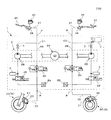
図1は、本実施の形態1に係る車体挙動制御装置1を含む液圧制御システム100の概要構成図である。
液圧制御システム100は、モーターサイクルに搭載され、車体の挙動を制御する車体挙動制御装置1を備えている。
<Overall configuration of hydraulic
FIG. 1 is a schematic configuration diagram of a hydraulic
The
モーターサイクルは、前輪20及び後輪30(単に車輪Wとも称する)を含む車体を備えている。前輪20の車軸及び後輪30の車軸は、車体に回転自在に固定されている。
モーターサイクルは、ユーザー等が操作するハンドルレバー24及びフットペダル34を備えている。このハンドルレバー24を操作すると前輪20の制動力が変化し、フットペダル34を操作すると後輪30の制動力が変化する。ハンドルレバー24は、運転者の手で操作され、フットペダル34は運転者の足で操作される。
The motorcycle includes a vehicle body including
The motorcycle includes a
液圧制御システム100は、前輪20の制動力の発生に利用されるブレーキ液が流れる前輪液圧回路C1と、後輪30の制動力の発生に利用されるブレーキ液が流れる後輪液圧回路C2とを含む。
The
液圧制御システム100は、前輪20に付設されるフロントブレーキパッド21と、フロントブレーキパッド21を動かすフロントブレーキピストン(図示省略)が摺動自在に設けられているフロントホイールシリンダ22と、フロントホイールシリンダ22に接続されたブレーキ液管23とを備えている。
The
液圧制御システム100は、ハンドルレバー24に付設される第1マスターシリンダ25と、ブレーキ液を貯留する第1リザーバ26と、第1マスターシリンダ25に接続されたブレーキ液管27とを備えている。なお、第1マスターシリンダ25には、マスターシリンダピストン(図示省略)が摺動自在に設けられている。ハンドルレバー24が操作されると、第1マスターシリンダ25内のマスターシリンダピストンが動く。
The hydraulic
液圧制御システム100は、後輪30に付設されるリアブレーキパッド31と、リアブレーキパッド31を動かすリアブレーキピストン(図示省略)が摺動自在に設けられているリアホイールシリンダ32と、リアホイールシリンダ32に接続されたブレーキ液管33とを備えている。
The
液圧制御システム100は、フットペダル34に付設される第2マスターシリンダ35と、ブレーキ液を貯留する第2リザーバ36と、第2マスターシリンダ35に接続されたブレーキ液管37とを備えている。なお、第2マスターシリンダ35には、マスターシリンダピストン(図示省略)が摺動自在に設けられている。フットペダル34が操作されると、第2マスターシリンダ35内のマスターシリンダピストンが動く。
The hydraulic
<車体挙動制御装置1の各部の構成>
車体挙動制御装置1は、ブレーキ液が流れる内部流路4と、内部流路4内のブレーキ液を第1マスターシリンダ25及び第2マスターシリンダ35側に搬送するのに用いられるポンプ装置2と、前輪液圧回路C1及び後輪液圧回路C2に設けられた開閉自在の調整弁3とを含む。なお、調整弁3は、第1増圧弁3A及び第1減圧弁3Bと、第2増圧弁3C及び第2減圧弁3Dとを含む。調整弁3は、例えば、ソレノイドを備えた電磁弁である。
ここで、本発明の挙動制御機構としてのブレーキ機構は、例えば調整弁3及びポンプ装置2等に対応し、それらの機構によって内部流路4の液圧が制御されて、車体の挙動が制御される。
<Configuration of each part of the vehicle body
The vehicle body
Here, the brake mechanism as the behavior control mechanism of the present invention corresponds to, for example, the regulating
また、車体挙動制御装置1は、調整弁3の開閉、ポンプ装置2の回転数等を制御する制御部7を含む。なお、制御部7の一部又は全ては、例えば、マイコン、マイクロプロセッサユニット等で構成されていてもよく、また、ファームウェア等の更新可能なもので構成されていてもよく、また、CPU等からの指令によって実行されるプログラムモジュール等であってもよい。
The vehicle body
さらに、車体挙動制御装置1は、制御部7に検出信号を出力する検出部8を含む。検出部8は、内部流路4に設けられた第1圧力センサ8A及び第2圧力センサ8Bと、車体の加速度を算出するのに用いられる前輪速度センサ8C及び後輪速度センサ8Dと(図5参照)、車体に設けられている加速度センサ8Eとを含む。
Furthermore, the vehicle body
車体挙動制御装置1は、ブレーキ液管23、27、33、37にそれぞれ接続される各種ポートPを含む。また、車体挙動制御装置1は、内部流路4を流れるブレーキ液の流量を規制するフロートリストリクタ5と、ブレーキ液を貯留可能なアキュムレータ6とを含む。
The vehicle body
なお、以下では、前輪速度及び後輪速度をまとめて車輪速度と称し、また、前輪速度センサ8C及び後輪速度センサ8Dをまとめて車輪速度センサWSと称する場合がある。
Hereinafter, the front wheel speed and the rear wheel speed may be collectively referred to as a wheel speed, and the front
内部流路4は、前輪液圧回路C1の一部を構成する第1内部流路4Aと、後輪液圧回路C2の一部を構成する第2内部流路4Bとを含む。
第1内部流路4Aには、第1増圧弁3A、第1減圧弁3B、及び第1圧力センサ8A等が設けられている。第1内部流路4Aは、ポートPを介してブレーキ液管23及びブレーキ液管27に接続されている。第2内部流路4Bには、第2増圧弁3C、第2減圧弁3D及び第2圧力センサ8B等が設けられている。第2内部流路4Bは、ポートPを介してブレーキ液管33及びブレーキ液管37に接続されている。
The
The first
ポンプ装置2は、例えばDCモーター等で構成することができる駆動機構2Aと、駆動機構2Aによって駆動力が与えられる2つのポンプエレメント2Bとを含む。駆動機構2Aは、固定子及び回転子等を含み、その回転数が制御部7によって制御される。一方のポンプエレメント2Bは、前輪液圧回路C1内のブレーキ液の搬送に用いられ、第1内部流路4Aに設けられている。他方のポンプエレメント2Bは、後輪液圧回路C2内のブレーキ液の搬送に用いられ、第2内部流路4Bに設けられている。
The
制御部7は、車体挙動制御のために、連動ブレーキ動作を実行する。
連動ブレーキ動作は、ハンドルレバー24によって前輪20に制動力を発生させる操作、又は、フットペダル34によって後輪30に制動力を発生させる操作が行われた際に、前輪20及び後輪30の両方に制動力を発生させる動作である。
つまり、制御部7は、別々の操作系統に接続されている複数の車輪Wのうちの一部の車輪Wを、その操作系統におけるユーザー等の操作に応じて制動する際に、その車輪Wと、それと異なる操作系統に接続されている他の車輪Wと、に制動力を生じさせる連動ブレーキ動作を実行する。
The
The interlocking brake operation is performed when both the
That is, when the
そして、制御部7は、路面の勾配値θを用いて算出された車輪Wの軸荷重に基づいて、連動ブレーキ動作を制御する。具体的には、制御部7は、ブレーキ機構である調整弁3の開閉、ポンプ装置2の回転数等を制御して、連動ブレーキ動作を実行する。
なお、制御部7は、路面の勾配値θを用いて、車輪Wの軸荷重を算出してもよく、また、路面の勾配値θに換算できる他の物理量を用いて、車輪Wの軸荷重を算出してもよい。また、制御部7は、車輪Wの軸荷重を用いて、連動ブレーキ動作を実行してもよく、また、車輪Wの軸荷重に換算できる他の物理量を用いて、連動ブレーキ動作を実行してもよい。
And the
The
<前輪20及び後輪30の軸荷重>
図2は、平地を走行するモーターサイクルの前輪20の軸荷重及び後輪30の軸荷重の説明図である。
質量mは、モーターサイクルの質量である。重心Gは、モーターサイクルの重心である。高さhは、路面からの重心Gまでの高さである。位置Cxは、水平方向における重心Gの位置である。位置Fxは、水平方向における前輪20の軸の位置である。位置Rxは、水平方向における後輪30の軸の位置である。荷重Fは、重心Gに作用するモーターサイクルの荷重である。荷重Fn_FAは、前輪20の軸荷重である。荷重Fn_RAは、後輪30の軸荷重である。モーターサイクルに搭乗している人の成分(質量、重心等)が加味されてもよい。また、モーターサイクルの加減速に起因する加速度成分が加味されてもよい。
<Axial load of
FIG. 2 is an explanatory diagram of the axial load of the
Mass m is the mass of the motorcycle. The center of gravity G is the center of gravity of the motorcycle. The height h is the height from the road surface to the center of gravity G. The position Cx is the position of the center of gravity G in the horizontal direction. The position Fx is the position of the axis of the
長さx1は、位置Cxと位置Fxとの間の長さである。長さx2は、位置Cxと位置Rxとの間の長さである。
なお、説明の便宜上、平坦な路面において、x1=x2が成立するように、モーターサイクルが設計されているものとする。まず、図2に示すように、モーターサイクルが、平坦な路面上にある場合について考える。
The length x1 is a length between the position Cx and the position Fx. The length x2 is a length between the position Cx and the position Rx.
For convenience of explanation, it is assumed that the motorcycle is designed so that x1 = x2 holds on a flat road surface. First, consider the case where the motorcycle is on a flat road as shown in FIG.
重力加速度をgとすると、モーターサイクルには下向きにm×gの荷重Fが掛かる。荷重Fを前輪20の軸にかかる成分及び後輪30の軸にかかる成分に分ける。前輪20の軸に掛かる荷重Fn_FA及び後輪30の軸に掛かる荷重Fn_RAは、次の式(1)及び式(2)のようになる。
If the gravitational acceleration is g, a load F of m × g is applied to the motorcycle downward. The load F is divided into a component applied to the
[数1]
Fn_FA=[1−{x1/(x1+x2)}]×m×g=m×g/2 ・・・(1)
[Equation 1]
Fn_FA = [1- {x1 / (x1 + x2)}] × m × g = m × g / 2 (1)
[数2]
Fn_RA=[1−{x2/(x1+x2)}]×m×g=m×g/2 ・・・(2)
[Equation 2]
Fn_RA = [1- {x2 / (x1 + x2)}] × m × g = m × g / 2 (2)
つまり、平坦な路面上において、荷重Fn_FA及び荷重Fn_RAの大きさは等しい。 That is, the magnitudes of the loads Fn_FA and Fn_RA are equal on a flat road surface.
図3は、上り勾配の路面を走行するモーターサイクルの前輪20の軸荷重及び後輪30の軸荷重の説明図である。次に、図3に示すように、モーターサイクルが、上り勾配の路面上にある場合を考える。
路面の勾配値θは、水平面を基準とする角度であり、上り勾配では正の値となり、下り勾配では負の値となる。高さhは、上り勾配の路面に直交する方向における、重心Gの高さである。位置Cx'は、水平方向における重心Gの位置である。位置Fx'は、水平方向における前輪20の軸の位置である。位置Rx'は、水平方向における後輪30の軸の位置である。荷重Fn_FA'は、前輪20の軸荷重である。荷重Fn_RA'は、後輪30の軸荷重である。
FIG. 3 is an explanatory diagram of the axial load of the
The slope value θ of the road surface is an angle with respect to the horizontal plane, and is a positive value for an ascending slope and a negative value for a descending slope. The height h is the height of the center of gravity G in the direction orthogonal to the road surface of the upward slope. The position Cx ′ is the position of the center of gravity G in the horizontal direction. The position Fx ′ is the position of the axis of the
長さx1'は、位置Cx'と位置Fx'との間の長さである。長さx2'は、位置Cx'と位置Rx'との間の長さである。長さx1'及び長さx2'は次のように計算することができる。 The length x1 ′ is a length between the position Cx ′ and the position Fx ′. The length x2 ′ is a length between the position Cx ′ and the position Rx ′. The length x1 ′ and the length x2 ′ can be calculated as follows.
[数3]
x1' = x1×cosθ + h×sinθ ・・・(3)
[Equation 3]
x1 ′ = x1 × cos θ + h × sin θ (3)
[数4]
x2' = x2×cosθ − h×sinθ ・・・(4)
[Equation 4]
x2 ′ = x2 × cos θ−h × sin θ (4)
したがって、前輪20の軸に掛かる荷重Fn_FA及び後輪30の軸に掛かる荷重Fn_RAは、次の式(5)及び式(6)のようになる。
Therefore, the load Fn_FA applied to the shaft of the
[数5]
Fn_FA'=[1−{x1'/(x1'+x2')}]×m×g
=[1−{(x1×cosθ+h×sinθ)/((x1+x2)×cosθ)}]×m×g ・・・(5)
[Equation 5]
Fn_FA ′ = [1- {x1 ′ / (x1 ′ + x2 ′)}] × m × g
= [1-{(x1 × cos θ + h × sin θ) / ((x1 + x2) × cos θ)}] × m × g (5)
[数6]
Fn_RA'=[1−{x2' / (x1'+x2')}]×m×g
=[1−{(x2×cosθ−h×sinθ)/((x1+x2)×cosθ)}]×m×g ・・・(6)
[Equation 6]
Fn_RA ′ = [1− {x2 ′ / (x1 ′ + x2 ′)}] × m × g
= [1-{(x2 × cos θ−h × sin θ) / ((x1 + x2) × cos θ)}] × m × g (6)
つまり、x1=x2である場合には、上り勾配の路面上において、荷重Fn_FA'よりも荷重Fn_RA'の方が大きくなる。また、路面の勾配値θが大きい(つまり上り勾配の勾配が大きい)程、荷重Fn_RA'が大きくなり、荷重Fn_FA'が小さくなる。 That is, when x1 = x2, the load Fn_RA ′ is larger than the load Fn_FA ′ on the road surface with an upward slope. In addition, the load Fn_RA ′ increases and the load Fn_FA ′ decreases as the road surface gradient value θ increases (that is, the ascending gradient increases).
図4は、下り勾配の路面を走行するモーターサイクルの前輪20の軸荷重及び後輪30の軸荷重の説明図である。下り勾配の路面を走行するモーターサイクルの前輪20の軸荷重及び後輪30の軸荷重も、図3で説明したことと同様の要領で、算出することができる。
FIG. 4 is an explanatory diagram of the axial load of the
つまり、x1=x2である場合には、下り勾配の路面上において、荷重Fn_RA'よりも荷重Fn_FA'の方が大きくなる。また、路面の勾配値θが小さい(つまり下り勾配の勾配が大きい)程、荷重Fn_FA'が大きくなり、荷重Fn_RA'が小さくなる。 That is, when x1 = x2, the load Fn_FA ′ is larger than the load Fn_RA ′ on the road surface having a downward slope. Further, the load Fn_FA ′ increases and the load Fn_RA ′ decreases as the road surface gradient value θ decreases (that is, the descending gradient increases).
軸荷重が小さい車輪Wよりも軸荷重が大きい車輪Wに、より大きな制動力を発生させることで、車体の挙動を安定化することができる。また、上述のとおり、各車輪Wの軸荷重は、路面の勾配値θから求めることができる。 By generating a larger braking force on the wheel W having a larger axial load than the wheel W having a smaller axial load, the behavior of the vehicle body can be stabilized. Further, as described above, the axial load of each wheel W can be obtained from the slope value θ of the road surface.
車体挙動制御装置1では、路面の勾配値θを算出し、その路面の勾配値θを用いて各車輪Wの軸荷重を取得する。そして、車体挙動制御装置1は、その軸荷重に基づいて、連動ブレーキ動作を実行することで、車体の挙動を安定化する。
The vehicle body
<制御部7の構成例>
図5は、本実施の形態1に係る車体挙動制御装置1を含む液圧制御システム100が備えている各種センサ、制御部7及び各種アクチュエータの機能ブロック図である。図6は、本実施の形態1に係る車体挙動制御装置1に含まれる制御部7の機能ブロック図である。図5及び図6を参照して、制御部7の構成例について説明する。
<Configuration Example of
FIG. 5 is a functional block diagram of various sensors, a
制御部7は、検出部8からの信号を受ける入力部7Aと、検出部8からの信号に基づいて車体が走行する路面の勾配値θを算出し、調整弁3の開閉、ポンプ装置2の回転数等の制御を実行するプロセッサ部7Bと、算出された路面の勾配値θ、各車輪Wの軸荷重等の各種のデータが格納される記憶部7Cとを含む。
The
(入力部7A)
入力部7Aは、例えば検出部8からの信号を受ける入力回路等を含む回路で構成されるものである。入力部7Aで受けた信号は、プロセッサ部7Bに出力される。
(
The
(プロセッサ部7B)
プロセッサ部7Bは、演算部T1と、アクチュエータ制御部T2とを含む。演算部T1は、車体速度算出部7B1と、勾配算出部7B2と、判定部7B3と、軸荷重算出部7B4と、車体挙動制御実行部7B5とを含む。プロセッサ部7Bは、例えばマイクロコントローラ等で構成することができる。
(Processor unit 7B)
The processor unit 7B includes a calculation unit T1 and an actuator control unit T2. The calculation unit T1 includes a vehicle body speed calculation unit 7B1, a gradient calculation unit 7B2, a determination unit 7B3, an axial load calculation unit 7B4, and a vehicle body behavior control execution unit 7B5. The processor unit 7B can be configured by, for example, a microcontroller.
車体速度算出部7B1は、車輪速度センサWSの検出信号に基づいて車体速度vVehを算出する。 The vehicle body speed calculation unit 7B1 calculates the vehicle body speed vVeh based on the detection signal of the wheel speed sensor WS.
勾配算出部7B2は、加速度センサ8Eの検出信号と、車輪速度センサWSの検出信号とに基づいて路面の勾配値θを算出する。ここで、本実施の形態1における路面の勾配値θの算出方法例について説明する。
The gradient calculation unit 7B2 calculates the road gradient value θ based on the detection signal of the
加速度センサ8Eの検出信号から得られる車体の進行方向における加速度成分aXは、車体の進行方向における加減速に起因する加速度成分aVehと、路面の勾配値θに起因する加速度成分aSlopeと、の和と看做すことができる。そのため、制御部7は、式(7)の演算によって、路面の勾配値θに起因する加速度成分aSlopeを推定することができる。なお、加減速に起因する加速度成分aVehは、車輪速度の微分値として求めることができ、例えば、制御部7は、車輪速度を車輪速度センサWSの検出信号から算出し、算出した車輪速度の微分値を、加減速に起因する加速度成分aVehとする。なお、路面の勾配値θに起因する加速度成分aSlopeは、上り勾配を走行中は正の値になり、下り勾配を走行中は負の値になる。
The acceleration component aX in the traveling direction of the vehicle body obtained from the detection signal of the
[数7]
aSlope = aX − aVeh ・・・(7)
[Equation 7]
aSlope = aX−aVeh (7)
そして、制御部7は、路面の勾配値θに起因する加速度成分aSlopeを用いて、式(8)を演算することで、路面の勾配値θを得ることができる。なお、路面の勾配値θは、上り勾配を走行中は正の値になり、下り勾配を走行中は負の値になる。
Then, the
[数8]
θ = arcsin( aSlope / g ) ・・・(8)
[Equation 8]
θ = arcsin (aSlope / g) (8)
このように、勾配算出部7B2は、加速度センサ8Eの検出信号と、車輪速度センサWSの検出信号とに基づいて、モーターサイクルが走行中の路面の勾配値θを算出することができる。
As described above, the gradient calculation unit 7B2 can calculate the gradient value θ of the road surface on which the motorcycle is traveling based on the detection signal of the
なお、制御部7の路面の勾配値θの算出方法は、上記に限定されるものではない。例えば、車体挙動制御装置1は、加速度センサ8Eとは別に勾配センサを備え、制御部7は、該勾配センサの検出信号から路面の勾配値θを取得してもよい。そのような場合には、上記の勾配算出部7B2の演算を行わないでよい分、制御部7の負荷を軽減することができる。
また、制御部7は、例えば、モーターサイクルが走行中の路面の勾配値θの情報を、GPS情報を元に取得してもよい。そのような場合でも、上記の勾配算出部7B2の演算を行わないでよい分、制御部7の負荷を軽減することができる。
The method of calculating the road surface gradient value θ of the
Moreover, the
判定部7B3は、勾配算出部7B2が算出した路面の勾配値θに基づいて、モーターサイクルが走行中の路面が上り勾配であるか、下り勾配であるか、又は、平坦であるかを判定する。これらの判定部7B3の判定は、後述される制動力配分フローに用いられる。 The determination unit 7B3 determines whether the road surface on which the motorcycle is traveling is an ascending slope, a descending slope, or a flat surface based on the slope value θ of the road surface calculated by the slope calculating unit 7B2. . These determinations by the determination unit 7B3 are used in a braking force distribution flow described later.
軸荷重算出部7B4は、勾配算出部7B2が算出した路面の勾配値θを用いて各車輪Wの軸荷重を算出する。なお、先述した式(1)〜(6)を考慮することで、各車輪Wの軸荷重を算出することができる。 The axial load calculation unit 7B4 calculates the axial load of each wheel W using the road gradient value θ calculated by the gradient calculation unit 7B2. In addition, the axial load of each wheel W is computable by considering Formula (1)-(6) mentioned above.
車体挙動制御実行部7B5は、軸荷重算出部7B4が算出した各車輪Wの軸荷重に基づいて、車体挙動制御としての連動ブレーキ動作を実行するための制御信号を生成し、アクチュエータ制御部T2に出力する。
路面の勾配値θに応じて各車輪Wにかかる軸荷重は変化する。したがって、車体挙動制御実行部7B5は、後述される制動力配分フローを実行して、各車輪Wの軸荷重に応じて各車輪Wに発生させる制動力の比率を変化させることで、モーターサイクルの挙動が不安定になることを抑制する。
The vehicle body behavior control execution unit 7B5 generates a control signal for executing the interlocking brake operation as the vehicle body behavior control based on the axial load of each wheel W calculated by the axial load calculation unit 7B4, and sends it to the actuator control unit T2. Output.
The axial load applied to each wheel W changes according to the gradient value θ of the road surface. Therefore, the vehicle body behavior control execution unit 7B5 executes a braking force distribution flow, which will be described later, and changes the ratio of the braking force generated in each wheel W according to the axial load of each wheel W, thereby Suppresses unstable behavior.
アクチュエータ制御部T2は、駆動機構制御部7B6と、弁制御部7B7とを含む。
連動ブレーキ動作の実行時に、弁制御部7B7は、調整弁3の開閉動作を制御し、駆動機構制御部7B6は、弁制御部7B7と協働して駆動機構2Aの回転数を制御する。
The actuator control unit T2 includes a drive mechanism control unit 7B6 and a valve control unit 7B7.
During execution of the interlocking brake operation, the valve control unit 7B7 controls the opening / closing operation of the regulating
(記憶部7C)
記憶部7Cには、前輪20及び後輪30の車輪速度の情報、プロセッサ部7Bで算出された情報、基準値等が格納されている。記憶部7Cは、例えばRAM(Random Access Memory)等で構成することができる。
(
The
<連動ブレーキ動作における制動力配分>
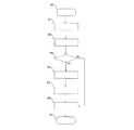
図7は、本実施の形態1に係る車体挙動制御装置1の前輪20及び後輪30の制動力配分フローの一例である。
<Brake force distribution in interlocking brake operation>
FIG. 7 is an example of a braking force distribution flow for the
(ステップS0:スタート)
制御部7は、制動力配分フローを開始する。
(Step S0: Start)
The
(ステップS1:制動力の基準値の取得)
制御部7の車体挙動制御実行部7B5は、例えば、車体速度算出部7B1が算出した車体速度vVehを用いて、前輪20及び後輪30に配分する制動力の基準値を設定する。なお、前輪20及び後輪30の制動力の基準値は、逐次算出されてもよいし、記憶部7Cに予め記憶されていてもよい。
(Step S1: Acquisition of braking force reference value)
The vehicle body behavior control execution unit 7B5 of the
(ステップS2:路面の勾配値θの算出)
制御部7の勾配算出部7B2は、加速度センサ8Eの検出信号及び車輪速度センサWSの検出信号に基づいて、車体が走行中の路面の勾配値θを算出する。
(Step S2: Calculation of the slope value θ of the road surface)
The gradient calculation unit 7B2 of the
(ステップS3:路面の勾配に関する判定)
制御部7の判定部7B3は、勾配算出部7B2が算出した路面の勾配値θに基づいて、路面が上り勾配であるか、下り勾配であるか、又は、平坦であるかを判定する。
路面が上り勾配又は下り勾配である場合には、ステップS4に移る。
路面が平坦である場合には、ステップS5に移る。
(Step S3: Determination regarding road surface gradient)
The determination unit 7B3 of the
If the road surface is uphill or downhill, the process proceeds to step S4.
If the road surface is flat, the process proceeds to step S5.
(ステップS4:各車輪Wの軸荷重の算出)
制御部7の軸荷重算出部7B4は、判定部7B3が上り勾配又は下り勾配であると判定していると、勾配算出部7B2が算出した路面の勾配値θに基づいて各車輪Wの軸荷重を算出する。
(Step S4: Calculation of the axial load of each wheel W)
The axial load calculation unit 7B4 of the
(ステップS5:制動力配分の修正)
制御部7の車体挙動制御実行部7B5は、軸荷重算出部7B4が算出した各車輪Wの軸荷重に基づいて、ステップS1で設定した前輪20の制動力及び後輪30の制動力の数値を修正する。
(Step S5: Correction of braking force distribution)
The vehicle body behavior control execution unit 7B5 of the
例えば、車体挙動制御実行部7B5は、路面が上り勾配である状態において、後輪30の軸荷重が大きい(路面の勾配値θが大きい)程、後輪30に配分される制動力の比率を大きくする。また、車体挙動制御実行部7B5は、路面が下り勾配である状態において、前輪20の軸荷重が大きい(路面の勾配値θが小さい)程、前輪20に配分される制動力の比率を大きくする。前輪20に配分される制動力の比率を大きくするにあたり、車体挙動制御実行部7B5は、後輪30に生じさせる制動力を低下させずに、前輪20に配分される制動力の比率を大きくするとよい。
For example, the vehicle body behavior control execution unit 7B5 sets the ratio of the braking force distributed to the
(ステップS6:制動力配分の設定)
制御部7は、ステップS3を経てきた場合にはステップS1で設定した前輪20及び後輪30の制動力の基準値を、制動力配分の設定値とする。
また、制御部7は、ステップS5を経てきた場合にはステップS5で修正した前輪20及び後輪30の制動力の数値を、制動力配分の設定値とする。
(Step S6: Setting of braking force distribution)
When the
Moreover, the
(ステップS7:エンド)
制御部7は、制動力配分フローを終了する。
(Step S7: End)
The
<本実施の形態1に係る車体挙動制御装置1の有する効果>
本実施の形態1に係る車体挙動制御装置1は、車体の挙動を制御する挙動制御機構と、路面の勾配値θを用いて算出された車輪Wの軸荷重に基づいて挙動制御機構の動作を制御する制御部7と、を備えている。このため、路面の勾配が変化する場合であっても、車体の挙動が不安定になることを抑制することができる。
<Effects of the vehicle body
The vehicle body
好ましくは、本実施の形態1に係る車体挙動制御装置1の挙動制御機構は、ブレーキ機構であり、制御部7は、挙動制御機構の動作として、ブレーキ機構が実行する車輪Wを制動する動作を、制御する。そして、この車輪Wを制動する動作は、ハンドルレバー24又はフットペダル34を介して、いずれかの車輪Wを制動する操作が行われた際に複数の車輪Wに制動力を発生させる連動ブレーキ動作である。このように、車体挙動制御装置1は、軸荷重を加味した上で、車輪Wを制動する連動ブレーキ動作を実行するため、連動ブレーキ動作の有効性を向上することができる。
Preferably, the behavior control mechanism of the vehicle body
好ましくは、本実施の形態1に係る車体挙動制御装置1の制御部7は、車輪Wの軸荷重に基づいて、連動ブレーキ動作における、複数の車輪Wのそれぞれに配分される制動力の比率を変化させる。
Preferably, the
例えば、本実施の形態1に係る車体挙動制御装置1の制御部7は、路面が上り勾配である状態において、後輪30の軸荷重が大きい(路面の勾配値θが大きい)程、後輪30に配分される制動力の比率を大きくする。上り勾配の路面の勾配が大きい(路面の勾配値θが大きい)程、後輪30の軸荷重が大きくなるので、それを踏まえて後輪30に発生させる制動力をより大きくすることで、モーターサイクルの挙動が不安定になることをより確実に抑制することができる。
For example, the
例えば、本実施の形態1に係る車体挙動制御装置1の制御部7は、路面が下り勾配である状態において、前輪20の軸荷重が大きい(路面の勾配値θが小さい)程、前輪20に配分される制動力の比率を大きくする。下り勾配の路面の勾配が大きい(路面の勾配値θが小さい)程、前輪20の軸荷重が大きくなるので、それを踏まえて前輪20に発生させる制動力をより大きくすることで、モーターサイクルの挙動が不安定になることをより確実に抑制することができる。
For example, the
例えば、本実施の形態1に係る車体挙動制御装置1の制御部7は、路面が下り勾配である状態において、後輪30に生じさせる制動力を低下させずに、前輪20に配分される制動力の比率を大きくする。下り勾配の路面を走行している場合には、モーターサイクルの自重がモーターサイクルの速度を上昇させるように作用するため、上り勾配の路面や平坦な路面を走行している場合と比較して、要求される制動力の総和が大きくなる。そのため、制御部7は、路面が下り勾配である場合の連動ブレーキ動作において、後輪30の制動力を低下させずに、前輪20に配分される制動力の比率を大きくして、制動力の不足が生じてしまうことを抑制する。
For example, the
実施の形態2.
以下では、実施の形態1と重複する説明を省略し、異なる部分のみを説明する。
Below, the description which overlaps with
<車体挙動制御装置1の各部の構成>
制御部7は、各車輪Wの軸荷重に基づいて各車輪Wに浮き上がりが生じているか否かを判定する。そして、制御部7は、その判定結果を、車体挙動制御としての、例えば、ABS制御、トラクションコントロール等に用いる。
ここで、ABS制御は、モーターサイクルの減速中に、車輪Wのロックを抑制する制御である。制御部7は、路面の勾配値θを用いて算出した車輪Wの軸荷重に基づいて、車輪Wの浮き上がりを判定し、ABS制御において、その判定結果を用いる。
また、トラクションコントロールは、モーターサイクルの走行中に、車輪Wの空転を抑制する制御である。制御部7は、路面の勾配値θを用いて算出した車輪Wの軸荷重に基づいて、車輪Wの浮き上がりを判定し、トラクションコントロールにおいて、その判定結果を用いる。
<Configuration of each part of the vehicle body
The
Here, the ABS control is a control for suppressing the lock of the wheel W during the deceleration of the motorcycle. The
In addition, the traction control is a control that suppresses idling of the wheels W while the motorcycle is traveling. The
例えば、下り勾配の路面を走行しているときにブレーキ操作がされ、車輪Wがロックしそうになっている状況を考える。下り勾配の路面を走行するモーターサイクルでは、前輪20の軸荷重が増加し、後輪30が浮き上がりやすくなる。制御部7は、そのような状況で、車輪Wの軸荷重に基づいて後輪30に浮き上がりが生じているか否かを判定する。制御部7は、後輪30の軸荷重のみを用いて、後輪30の浮き上がりを判定してもよく、また、車輪速度及び車体速度vVehから算出される後輪30のスリップ率と、後輪30の軸荷重と、を用いて、後輪30の浮き上がりを判定してもよい。制御部7は、後輪30の軸荷重を用いてもよく、また、後輪30の軸荷重に換算できる他の物理量(例えば、前輪20の軸荷重等)を用いてもよい。
For example, consider a situation in which a brake operation is performed while the vehicle is traveling on a downhill road surface and the wheels W are about to lock. In a motorcycle traveling on a downhill road surface, the axial load of the
仮に、制御部7が、車輪速度及び車体速度vVehから算出される後輪30のスリップ率のみを使用して後輪30の浮き上がりを判定する場合には、下り勾配によって後輪30が浮き上がりやすくなっていることが加味されず、後輪30の浮き上がりの判定が不正確となって、ABS制御の有効性が低減されてしまう。一方、上述のように、制御部7が、車輪Wの軸荷重に基づいて後輪30に浮き上がりが生じているか否かを判定する場合には、下り勾配によって後輪30が浮き上がりやすくなっていることが加味されて、後輪30の浮き上がりの判定が正確化され、ABS制御の有効性が向上される。
If the
なお、ここでは、モーターサイクルが下り勾配の路面を走行しているときのABS制御について説明しているが、モーターサイクルが上り勾配の路面を走行しているときのABS制御においても、車輪Wの軸荷重を用いることで、車輪Wに浮き上がりが生じているか否かの判定が正確化される。モーターサイクルが下り勾配の路面を走行しているときには、その有効性が一層高まる。 Here, the ABS control when the motorcycle is traveling on a downhill road surface has been described, but the ABS control when the motorcycle is traveling on an uphill road surface is also described. By using the axial load, it is possible to accurately determine whether or not the wheel W is lifted. When the motorcycle is traveling on a downhill road surface, its effectiveness is further enhanced.
例えば、上り勾配の路面を走行しているときにモーターサイクルが加速され、車輪Wが空転しそうになっている状況を考える。上り勾配の路面を走行するモーターサイクルでは、後輪30の軸荷重が増加し、前輪20が浮き上がりやすくなる。制御部7は、そのような状況で、車輪Wの軸荷重に基づいて前輪20に浮き上がりが生じているか否かを判定する。制御部7は、前輪20の軸荷重のみを用いて、前輪20の浮き上がりを判定してもよく、また、車輪速度及び車体速度vVehから算出される前輪20のスリップ率と、前輪20の軸荷重と、を用いて、前輪20の浮き上がりを判定してもよい。制御部7は、前輪20の軸荷重を用いてもよく、また、前輪20の軸荷重に換算できる他の物理量(例えば、後輪30の軸荷重等)を用いてもよい。
For example, consider a situation in which the motorcycle is accelerated when traveling on an uphill road surface and the wheels W are about to slip. In a motorcycle that travels on an ascending road surface, the axial load of the
仮に、制御部7が、車輪速度及び車体速度vVehから算出される前輪20のスリップ率のみを使用して前輪20の浮き上がりを判定する場合には、上り勾配によって前輪20が浮き上がりやすくなっていることが加味されず、前輪20の浮き上がりの判定が不正確となって、トラクションコントロールの有効性が低減されてしまう。一方、上述のように、制御部7が、車輪Wの軸荷重に基づいて前輪20に浮き上がりが生じているか否かを判定する場合には、上り勾配によって前輪20が浮き上がりやすくなっていることが加味されて、前輪20の浮き上がりの判定が正確化され、トラクションコントロールの有効性が向上される。
If the
なお、ここでは、モーターサイクルが上り勾配の路面を走行しているときのトラクションコントロールについて説明しているが、モーターサイクルが下り勾配の路面を走行しているときのトラクションコントロールにおいても、車輪Wの軸荷重を用いることで、車輪Wに浮き上がりが生じているか否かの判定が正確化される。モーターサイクルが上り勾配の路面を走行しているときには、その有効性が一層高まる。 In addition, although the traction control when the motorcycle is traveling on an uphill road surface is described here, the traction control when the motorcycle is traveling on a downhill road surface is also described. By using the axial load, it is possible to accurately determine whether or not the wheel W is lifted. When the motorcycle is traveling on an uphill road surface, its effectiveness is further enhanced.
<本実施の形態2に係る車体挙動制御装置1の有する効果>
本実施の形態2に係る車体挙動制御装置1の制御部7は、車輪Wの軸荷重に基づいて車輪Wの浮き上がりを検出する。そのため、車輪Wの浮き上がりの判定が正確化されて、車体の挙動が不安定になることを抑制することができる。
<Effects of the vehicle body
The
以上、実施の形態1及び実施の形態2について説明したが、本発明は各実施の形態の説明に限定されない。例えば、各実施の形態の全て又は一部が組み合わされてもよい。
As mentioned above, although
1 車体挙動制御装置、2 ポンプ装置、2A 駆動機構、2B ポンプエレメント、3 調整弁、3A 第1増圧弁、3B 第1減圧弁、3C 第2増圧弁、3D 第2減圧弁、4 内部流路、4A 第1内部流路、4B 第2内部流路、5 フロートリストリクタ、6 アキュムレータ、7 制御部、7A 入力部、7B プロセッサ部、7B1 車体速度算出部、7B2 勾配算出部、7B3 判定部、7B4 軸荷重算出部、7B5 車体挙動制御実行部、7B6 駆動機構制御部、7B7 弁制御部、7C 記憶部、8 検出部、8A 第1圧力センサ、8B 第2圧力センサ、8C 前輪速度センサ、8D 後輪速度センサ、8E 加速度センサ、20 前輪、21 フロントブレーキパッド、22 フロントホイールシリンダ、23 ブレーキ液管、24 ハンドルレバー、25 第1マスターシリンダ、26 第1リザーバ、27 ブレーキ液管、30 後輪、31 リアブレーキパッド、32 リアホイールシリンダ、33 ブレーキ液管、34 フットペダル、35 第2マスターシリンダ、36 第2リザーバ、37 ブレーキ液管、100 液圧制御システム、C1 前輪液圧回路、C2 後輪液圧回路、G 重心、P ポート、T1 演算部、T2 アクチュエータ制御部、W 車輪、WS 車輪速度センサ。 DESCRIPTION OF SYMBOLS 1 Vehicle body behavior control apparatus, 2 pump apparatus, 2A drive mechanism, 2B pump element, 3 adjustment valve, 3A 1st pressure increase valve, 3B 1 pressure reduction valve, 3C 2nd pressure increase valve, 3D 2nd pressure reduction valve, 4 internal flow path 4A 1st internal flow path, 4B 2nd internal flow path, 5 float restrictor, 6 accumulator, 7 control section, 7A input section, 7B processor section, 7B1 vehicle body speed calculation section, 7B2 gradient calculation section, 7B3 determination section, 7B4 Axial load calculation unit, 7B5 Car body behavior control execution unit, 7B6 Drive mechanism control unit, 7B7 Valve control unit, 7C Storage unit, 8 detection unit, 8A first pressure sensor, 8B second pressure sensor, 8C front wheel speed sensor, 8D Rear wheel speed sensor, 8E acceleration sensor, 20 front wheel, 21 front brake pad, 22 front wheel cylinder, 23 brake fluid pipe, 2 4 Handle lever, 25 First master cylinder, 26 First reservoir, 27 Brake fluid pipe, 30 Rear wheel, 31 Rear brake pad, 32 Rear wheel cylinder, 33 Brake fluid pipe, 34 Foot pedal, 35 Second master cylinder, 36 Second reservoir, 37 Brake fluid pipe, 100 Fluid pressure control system, C1 Front wheel fluid pressure circuit, C2 Rear wheel fluid pressure circuit, G Center of gravity, P port, T1 calculation unit, T2 Actuator control unit, W wheel, WS Wheel speed sensor .
Claims (9)
前記車体の挙動を制御する挙動制御機構と、
路面の勾配値を用いて算出された車輪の軸荷重に基づいて、前記挙動制御機構の動作を制御する制御部と、
を備えている、
車体挙動制御装置。 A vehicle body behavior control device incorporated in a vehicle body including a plurality of wheels,
A behavior control mechanism for controlling the behavior of the vehicle body;
A control unit that controls the operation of the behavior control mechanism, based on the wheel load calculated using the gradient value of the road surface;
With
Body behavior control device.
前記制御部は、前記挙動制御機構の動作としての、前記ブレーキ機構が実行する車輪を制動する動作を、制御する、
請求項1に記載の車体挙動制御装置。 The behavior control mechanism is a brake mechanism,
The control unit controls an operation of braking the wheel executed by the brake mechanism as an operation of the behavior control mechanism.
The vehicle body behavior control device according to claim 1.
請求項2に記載の車体挙動制御装置。 The operation of braking the wheel is an interlocking brake operation that generates a braking force on a plurality of wheels when an operation of braking any of the wheels is performed.
The vehicle body behavior control device according to claim 2.
車輪の前記軸荷重に基づいて、前記連動ブレーキ動作における、複数の車輪のそれぞれに配分される前記制動力の比率を変化させる、
請求項3に記載の車体挙動制御装置。 The controller is
Based on the wheel load of the wheel, the ratio of the braking force distributed to each of the plurality of wheels in the interlock brake operation is changed.
The vehicle body behavior control device according to claim 3.
前記路面が上り勾配である状態において、後輪の前記軸荷重が大きい程、後輪に配分される前記制動力の比率を大きくする、
請求項4に記載の車体挙動制御装置。 The controller is
In the state where the road surface is ascending, the ratio of the braking force distributed to the rear wheel is increased as the axial load of the rear wheel is larger.
The vehicle body behavior control device according to claim 4.
前記路面が下り勾配である状態において、前輪の前記軸荷重が大きい程、前輪に配分される前記制動力の比率を大きくする、
請求項4又は5に記載の車体挙動制御装置。 The controller is
In the state where the road surface is in a downward slope, the ratio of the braking force distributed to the front wheels is increased as the axial load of the front wheels is increased.
The vehicle body behavior control device according to claim 4 or 5.
前記路面が下り勾配である状態において、後輪に生じさせる前記制動力を低下させずに、前輪に配分される前記制動力の比率を大きくする、
請求項6に記載の車体挙動制御装置。 The controller is
In a state where the road surface is in a downward slope, the ratio of the braking force distributed to the front wheels is increased without reducing the braking force generated on the rear wheels.
The vehicle body behavior control device according to claim 6.
車輪の前記軸荷重に基づいて車輪の浮き上がりを検出する、
請求項1〜7のいずれか一項に記載の車体挙動制御装置。 The controller is
Detecting the lifting of the wheel based on the wheel load of the wheel,
The vehicle body behavior control apparatus according to any one of claims 1 to 7.
前記車体の挙動を制御する挙動制御機構の動作を、
路面の勾配値を用いて算出された車輪の軸荷重に基づいて制御する、
車体の挙動の制御方法。
A method for controlling the behavior of a vehicle body including a plurality of wheels,
The operation of the behavior control mechanism that controls the behavior of the vehicle body,
Control based on the wheel load calculated using the slope value of the road surface,
Control method for vehicle behavior.
Priority Applications (6)
| Application Number | Priority Date | Filing Date | Title |
|---|---|---|---|
| JP2015120768A JP2017001636A (en) | 2015-06-16 | 2015-06-16 | Vehicle body behavior control device and vehicle body behavior control method |
| TW105112795A TWI694947B (en) | 2015-06-16 | 2016-04-25 | Vehicle body behavior control device and method of controlling behavior of vehicle body |
| US15/735,392 US10668903B2 (en) | 2015-06-16 | 2016-06-02 | Vehicle body behavior control device and method of controlling behavior of vehicle body |
| PCT/IB2016/053235 WO2017037549A1 (en) | 2015-06-16 | 2016-06-02 | Vehicle body behavior control device and method of controlling behavior of vehicle body |
| EP16731971.4A EP3312064B1 (en) | 2015-06-16 | 2016-06-02 | Vehicle body behavior control device and method of controlling behavior of vehicle body |
| JP2017537030A JP6491340B2 (en) | 2015-06-16 | 2016-06-02 | Car body behavior control device and car body behavior control method |
Applications Claiming Priority (1)
| Application Number | Priority Date | Filing Date | Title |
|---|---|---|---|
| JP2015120768A JP2017001636A (en) | 2015-06-16 | 2015-06-16 | Vehicle body behavior control device and vehicle body behavior control method |
Publications (1)
| Publication Number | Publication Date |
|---|---|
| JP2017001636A true JP2017001636A (en) | 2017-01-05 |
Family
ID=56203433
Family Applications (2)
| Application Number | Title | Priority Date | Filing Date |
|---|---|---|---|
| JP2015120768A Pending JP2017001636A (en) | 2015-06-16 | 2015-06-16 | Vehicle body behavior control device and vehicle body behavior control method |
| JP2017537030A Active JP6491340B2 (en) | 2015-06-16 | 2016-06-02 | Car body behavior control device and car body behavior control method |
Family Applications After (1)
| Application Number | Title | Priority Date | Filing Date |
|---|---|---|---|
| JP2017537030A Active JP6491340B2 (en) | 2015-06-16 | 2016-06-02 | Car body behavior control device and car body behavior control method |
Country Status (5)
| Country | Link |
|---|---|
| US (1) | US10668903B2 (en) |
| EP (1) | EP3312064B1 (en) |
| JP (2) | JP2017001636A (en) |
| TW (1) | TWI694947B (en) |
| WO (1) | WO2017037549A1 (en) |
Cited By (4)
| Publication number | Priority date | Publication date | Assignee | Title |
|---|---|---|---|---|
| JP2018149996A (en) * | 2017-03-14 | 2018-09-27 | 日信工業株式会社 | Brake hydraulic control device for bar handle vehicle |
| JPWO2021165774A1 (en) * | 2020-02-17 | 2021-08-26 | ||
| JPWO2022074581A1 (en) * | 2020-10-09 | 2022-04-14 | ||
| CN115158255A (en) * | 2022-07-27 | 2022-10-11 | 深圳哲轮科技有限公司 | Bicycle brake control method and device, electronic equipment and medium |
Families Citing this family (3)
| Publication number | Priority date | Publication date | Assignee | Title |
|---|---|---|---|---|
| TWI758301B (en) | 2016-06-28 | 2022-03-21 | 美商陶氏全球科技有限責任公司 | Multilayer films, articles comprising the same, methods of manufacturing multilayer films |
| JP6830882B2 (en) * | 2017-10-20 | 2021-02-17 | 株式会社シマノ | Brake control and brake system |
| JP7404000B2 (en) * | 2019-09-04 | 2023-12-25 | カワサキモータース株式会社 | Wheelie suppression control device |
Family Cites Families (16)
| Publication number | Priority date | Publication date | Assignee | Title |
|---|---|---|---|---|
| JP3457190B2 (en) | 1998-09-03 | 2003-10-14 | 株式会社ボッシュオートモーティブシステム | Motorcycle brake control device |
| JP4283039B2 (en) * | 1999-07-01 | 2009-06-24 | 株式会社日立製作所 | Automobile traveling control device and automobile |
| JP4565757B2 (en) * | 2001-03-05 | 2010-10-20 | トヨタ自動車株式会社 | Vehicle running state control device |
| FR2843350B1 (en) | 2002-08-06 | 2005-04-01 | Renault Sa | METHOD FOR CONTROLLING THE BRAKING OF WHEELS OF A MOTOR VEHICLE, DEVICE FOR CONTROLLING THE DISTRIBUTION OF BRAKE EFFORTS AND VEHICLE EQUIPPED WITH SUCH A DEVICE |
| DE102004034067A1 (en) * | 2004-07-15 | 2006-02-09 | Bayerische Motoren Werke Ag | Method for stabilizing vehicle during braking operation on inclined surface, comprising shifting of activation point of torque regulating device |
| DE102007025272A1 (en) | 2006-06-14 | 2007-12-27 | Continental Teves Ag & Co. Ohg | Detection method for initiation of starting process of motorcycle by rider, involves measuring state variables e.g. throttle flap angle and engine rotational speed of motorcycle |
| DE102006031231B4 (en) | 2006-07-06 | 2021-09-23 | Bayerische Motoren Werke Aktiengesellschaft | Brake control system for motor vehicles |
| DE102007009860B4 (en) * | 2007-02-28 | 2022-05-25 | Zf Active Safety Gmbh | Method and device for speed control when driving downhill |
| JP2009051310A (en) * | 2007-08-24 | 2009-03-12 | Advics:Kk | Vehicle traveling controller |
| JP5156717B2 (en) | 2009-10-26 | 2013-03-06 | 日立オートモティブシステムズ株式会社 | Brake control device for motorcycles |
| DE102011079134A1 (en) | 2011-07-14 | 2013-01-17 | Continental Teves Ag & Co. Ohg | Method for speed control of motorcycle when driving on sloping ground, involves controlling brake after activation request by driver of motorcycle where predetermined target speed of motorcycle is established |
| US9090232B2 (en) | 2011-11-08 | 2015-07-28 | Toyota Jidosha Kabushiki Kaisha | Vehicle braking/driving force control device |
| JP5457495B2 (en) * | 2012-05-02 | 2014-04-02 | 富士重工業株式会社 | Vehicle control device |
| DE102013217593A1 (en) | 2013-09-04 | 2015-03-05 | Robert Bosch Gmbh | Method for determining a maximum permissible braking deceleration of a single-track vehicle |
| JP6257273B2 (en) | 2013-11-05 | 2018-01-10 | ボッシュ株式会社 | Brake control device |
| JP5997735B2 (en) * | 2014-08-08 | 2016-09-28 | 本田技研工業株式会社 | Braking force control device for saddle riding type vehicle |
-
2015
- 2015-06-16 JP JP2015120768A patent/JP2017001636A/en active Pending
-
2016
- 2016-04-25 TW TW105112795A patent/TWI694947B/en active
- 2016-06-02 US US15/735,392 patent/US10668903B2/en active Active
- 2016-06-02 WO PCT/IB2016/053235 patent/WO2017037549A1/en active Application Filing
- 2016-06-02 EP EP16731971.4A patent/EP3312064B1/en active Active
- 2016-06-02 JP JP2017537030A patent/JP6491340B2/en active Active
Cited By (7)
| Publication number | Priority date | Publication date | Assignee | Title |
|---|---|---|---|---|
| JP2018149996A (en) * | 2017-03-14 | 2018-09-27 | 日信工業株式会社 | Brake hydraulic control device for bar handle vehicle |
| JPWO2021165774A1 (en) * | 2020-02-17 | 2021-08-26 | ||
| JP7419493B2 (en) | 2020-02-17 | 2024-01-22 | ロベルト・ボッシュ・ゲゼルシャフト・ミト・ベシュレンクテル・ハフツング | Control device and control method |
| JPWO2022074581A1 (en) * | 2020-10-09 | 2022-04-14 | ||
| JP7531601B2 (en) | 2020-10-09 | 2024-08-09 | ロベルト・ボッシュ・ゲゼルシャフト・ミト・ベシュレンクテル・ハフツング | Control device and control method |
| CN115158255A (en) * | 2022-07-27 | 2022-10-11 | 深圳哲轮科技有限公司 | Bicycle brake control method and device, electronic equipment and medium |
| CN115158255B (en) * | 2022-07-27 | 2024-03-22 | 深圳哲轮科技有限公司 | Bicycle brake control method and device, electronic equipment and medium |
Also Published As
| Publication number | Publication date |
|---|---|
| WO2017037549A1 (en) | 2017-03-09 |
| JP6491340B2 (en) | 2019-03-27 |
| TW201706171A (en) | 2017-02-16 |
| JPWO2017037549A1 (en) | 2018-03-15 |
| TWI694947B (en) | 2020-06-01 |
| EP3312064A1 (en) | 2018-04-25 |
| US20180178768A1 (en) | 2018-06-28 |
| US10668903B2 (en) | 2020-06-02 |
| EP3312064B1 (en) | 2021-01-20 |
Similar Documents
| Publication | Publication Date | Title |
|---|---|---|
| JP6491340B2 (en) | Car body behavior control device and car body behavior control method | |
| JP6491335B2 (en) | Car body behavior control device and car body behavior control method | |
| JP6262202B2 (en) | Brake control device and straddle-type vehicle equipped with the same | |
| JPWO2018185578A1 (en) | Control device, control method, and brake system | |
| US12043236B2 (en) | Controller and control method | |
| JP5456526B2 (en) | Motorcycle braking device | |
| JPWO2017109613A1 (en) | Control apparatus and control method | |
| JP7531601B2 (en) | Control device and control method | |
| EP4378769A1 (en) | Controller for a saddled vehicle and control method for maneuvering a saddled vehicle | |
| JP5797573B2 (en) | Vehicle control device | |
| JP2016222209A (en) | Driving control device and driving control method | |
| JP2022062851A (en) | Control device and control method | |
| JP2013028258A (en) | Device for estimating longitudinal acceleration |