JP4282994B2 - Method and apparatus for catheter-based annuloplasty using local plication - Google Patents
Method and apparatus for catheter-based annuloplasty using local plication Download PDFInfo
- Publication number
- JP4282994B2 JP4282994B2 JP2002582832A JP2002582832A JP4282994B2 JP 4282994 B2 JP4282994 B2 JP 4282994B2 JP 2002582832 A JP2002582832 A JP 2002582832A JP 2002582832 A JP2002582832 A JP 2002582832A JP 4282994 B2 JP4282994 B2 JP 4282994B2
- Authority
- JP
- Japan
- Prior art keywords
- catheter
- tissue
- mitral valve
- plication
- heart
- Prior art date
- Legal status (The legal status is an assumption and is not a legal conclusion. Google has not performed a legal analysis and makes no representation as to the accuracy of the status listed.)
- Expired - Lifetime
Links
Images


Classifications
-
- A—HUMAN NECESSITIES
- A61—MEDICAL OR VETERINARY SCIENCE; HYGIENE
- A61B—DIAGNOSIS; SURGERY; IDENTIFICATION
- A61B17/00—Surgical instruments, devices or methods, e.g. tourniquets
- A61B17/064—Surgical staples, i.e. penetrating the tissue
- A61B17/0644—Surgical staples, i.e. penetrating the tissue penetrating the tissue, deformable to closed position
-
- A—HUMAN NECESSITIES
- A61—MEDICAL OR VETERINARY SCIENCE; HYGIENE
- A61B—DIAGNOSIS; SURGERY; IDENTIFICATION
- A61B17/00—Surgical instruments, devices or methods, e.g. tourniquets
- A61B17/04—Surgical instruments, devices or methods, e.g. tourniquets for suturing wounds; Holders or packages for needles or suture materials
- A61B17/0401—Suture anchors, buttons or pledgets, i.e. means for attaching sutures to bone, cartilage or soft tissue; Instruments for applying or removing suture anchors
-
- A—HUMAN NECESSITIES
- A61—MEDICAL OR VETERINARY SCIENCE; HYGIENE
- A61B—DIAGNOSIS; SURGERY; IDENTIFICATION
- A61B17/00—Surgical instruments, devices or methods, e.g. tourniquets
- A61B17/04—Surgical instruments, devices or methods, e.g. tourniquets for suturing wounds; Holders or packages for needles or suture materials
- A61B17/0487—Suture clamps, clips or locks, e.g. for replacing suture knots; Instruments for applying or removing suture clamps, clips or locks
-
- A—HUMAN NECESSITIES
- A61—MEDICAL OR VETERINARY SCIENCE; HYGIENE
- A61B—DIAGNOSIS; SURGERY; IDENTIFICATION
- A61B17/00—Surgical instruments, devices or methods, e.g. tourniquets
- A61B17/064—Surgical staples, i.e. penetrating the tissue
-
- A—HUMAN NECESSITIES
- A61—MEDICAL OR VETERINARY SCIENCE; HYGIENE
- A61B—DIAGNOSIS; SURGERY; IDENTIFICATION
- A61B17/00—Surgical instruments, devices or methods, e.g. tourniquets
- A61B17/064—Surgical staples, i.e. penetrating the tissue
- A61B17/0643—Surgical staples, i.e. penetrating the tissue with separate closing member, e.g. for interlocking with staple
-
- A—HUMAN NECESSITIES
- A61—MEDICAL OR VETERINARY SCIENCE; HYGIENE
- A61B—DIAGNOSIS; SURGERY; IDENTIFICATION
- A61B17/00—Surgical instruments, devices or methods, e.g. tourniquets
- A61B17/08—Wound clamps or clips, i.e. not or only partly penetrating the tissue ; Devices for bringing together the edges of a wound
-
- A—HUMAN NECESSITIES
- A61—MEDICAL OR VETERINARY SCIENCE; HYGIENE
- A61B—DIAGNOSIS; SURGERY; IDENTIFICATION
- A61B17/00—Surgical instruments, devices or methods, e.g. tourniquets
- A61B2017/00004—(bio)absorbable, (bio)resorbable, resorptive
-
- A—HUMAN NECESSITIES
- A61—MEDICAL OR VETERINARY SCIENCE; HYGIENE
- A61B—DIAGNOSIS; SURGERY; IDENTIFICATION
- A61B17/00—Surgical instruments, devices or methods, e.g. tourniquets
- A61B17/00234—Surgical instruments, devices or methods, e.g. tourniquets for minimally invasive surgery
- A61B2017/00238—Type of minimally invasive operation
- A61B2017/00243—Type of minimally invasive operation cardiac
-
- A—HUMAN NECESSITIES
- A61—MEDICAL OR VETERINARY SCIENCE; HYGIENE
- A61B—DIAGNOSIS; SURGERY; IDENTIFICATION
- A61B17/00—Surgical instruments, devices or methods, e.g. tourniquets
- A61B2017/00743—Type of operation; Specification of treatment sites
- A61B2017/00778—Operations on blood vessels
- A61B2017/00783—Valvuloplasty
-
- A—HUMAN NECESSITIES
- A61—MEDICAL OR VETERINARY SCIENCE; HYGIENE
- A61B—DIAGNOSIS; SURGERY; IDENTIFICATION
- A61B17/00—Surgical instruments, devices or methods, e.g. tourniquets
- A61B2017/00831—Material properties
- A61B2017/00867—Material properties shape memory effect
-
- A—HUMAN NECESSITIES
- A61—MEDICAL OR VETERINARY SCIENCE; HYGIENE
- A61B—DIAGNOSIS; SURGERY; IDENTIFICATION
- A61B17/00—Surgical instruments, devices or methods, e.g. tourniquets
- A61B17/04—Surgical instruments, devices or methods, e.g. tourniquets for suturing wounds; Holders or packages for needles or suture materials
- A61B17/0401—Suture anchors, buttons or pledgets, i.e. means for attaching sutures to bone, cartilage or soft tissue; Instruments for applying or removing suture anchors
- A61B2017/0406—Pledgets
-
- A—HUMAN NECESSITIES
- A61—MEDICAL OR VETERINARY SCIENCE; HYGIENE
- A61B—DIAGNOSIS; SURGERY; IDENTIFICATION
- A61B17/00—Surgical instruments, devices or methods, e.g. tourniquets
- A61B17/04—Surgical instruments, devices or methods, e.g. tourniquets for suturing wounds; Holders or packages for needles or suture materials
- A61B17/0401—Suture anchors, buttons or pledgets, i.e. means for attaching sutures to bone, cartilage or soft tissue; Instruments for applying or removing suture anchors
- A61B2017/0409—Instruments for applying suture anchors
-
- A—HUMAN NECESSITIES
- A61—MEDICAL OR VETERINARY SCIENCE; HYGIENE
- A61B—DIAGNOSIS; SURGERY; IDENTIFICATION
- A61B17/00—Surgical instruments, devices or methods, e.g. tourniquets
- A61B17/04—Surgical instruments, devices or methods, e.g. tourniquets for suturing wounds; Holders or packages for needles or suture materials
- A61B17/0401—Suture anchors, buttons or pledgets, i.e. means for attaching sutures to bone, cartilage or soft tissue; Instruments for applying or removing suture anchors
- A61B2017/0417—T-fasteners
-
- A—HUMAN NECESSITIES
- A61—MEDICAL OR VETERINARY SCIENCE; HYGIENE
- A61B—DIAGNOSIS; SURGERY; IDENTIFICATION
- A61B17/00—Surgical instruments, devices or methods, e.g. tourniquets
- A61B17/04—Surgical instruments, devices or methods, e.g. tourniquets for suturing wounds; Holders or packages for needles or suture materials
- A61B17/0401—Suture anchors, buttons or pledgets, i.e. means for attaching sutures to bone, cartilage or soft tissue; Instruments for applying or removing suture anchors
- A61B2017/0419—H-fasteners
-
- A—HUMAN NECESSITIES
- A61—MEDICAL OR VETERINARY SCIENCE; HYGIENE
- A61B—DIAGNOSIS; SURGERY; IDENTIFICATION
- A61B17/00—Surgical instruments, devices or methods, e.g. tourniquets
- A61B17/04—Surgical instruments, devices or methods, e.g. tourniquets for suturing wounds; Holders or packages for needles or suture materials
- A61B17/0401—Suture anchors, buttons or pledgets, i.e. means for attaching sutures to bone, cartilage or soft tissue; Instruments for applying or removing suture anchors
- A61B2017/0464—Suture anchors, buttons or pledgets, i.e. means for attaching sutures to bone, cartilage or soft tissue; Instruments for applying or removing suture anchors for soft tissue
-
- A—HUMAN NECESSITIES
- A61—MEDICAL OR VETERINARY SCIENCE; HYGIENE
- A61B—DIAGNOSIS; SURGERY; IDENTIFICATION
- A61B17/00—Surgical instruments, devices or methods, e.g. tourniquets
- A61B17/04—Surgical instruments, devices or methods, e.g. tourniquets for suturing wounds; Holders or packages for needles or suture materials
- A61B17/0469—Suturing instruments for use in minimally invasive surgery, e.g. endoscopic surgery
- A61B2017/0472—Multiple-needled, e.g. double-needled, instruments
-
- A—HUMAN NECESSITIES
- A61—MEDICAL OR VETERINARY SCIENCE; HYGIENE
- A61B—DIAGNOSIS; SURGERY; IDENTIFICATION
- A61B17/00—Surgical instruments, devices or methods, e.g. tourniquets
- A61B17/04—Surgical instruments, devices or methods, e.g. tourniquets for suturing wounds; Holders or packages for needles or suture materials
- A61B17/0469—Suturing instruments for use in minimally invasive surgery, e.g. endoscopic surgery
- A61B2017/048—Suturing instruments for use in minimally invasive surgery, e.g. endoscopic surgery for reducing heart wall tension, e.g. sutures with a pad on each extremity
-
- A—HUMAN NECESSITIES
- A61—MEDICAL OR VETERINARY SCIENCE; HYGIENE
- A61B—DIAGNOSIS; SURGERY; IDENTIFICATION
- A61B17/00—Surgical instruments, devices or methods, e.g. tourniquets
- A61B17/04—Surgical instruments, devices or methods, e.g. tourniquets for suturing wounds; Holders or packages for needles or suture materials
- A61B17/0487—Suture clamps, clips or locks, e.g. for replacing suture knots; Instruments for applying or removing suture clamps, clips or locks
- A61B2017/0488—Instruments for applying suture clamps, clips or locks
-
- A—HUMAN NECESSITIES
- A61—MEDICAL OR VETERINARY SCIENCE; HYGIENE
- A61B—DIAGNOSIS; SURGERY; IDENTIFICATION
- A61B17/00—Surgical instruments, devices or methods, e.g. tourniquets
- A61B17/04—Surgical instruments, devices or methods, e.g. tourniquets for suturing wounds; Holders or packages for needles or suture materials
- A61B2017/0496—Surgical instruments, devices or methods, e.g. tourniquets for suturing wounds; Holders or packages for needles or suture materials for tensioning sutures
-
- A—HUMAN NECESSITIES
- A61—MEDICAL OR VETERINARY SCIENCE; HYGIENE
- A61B—DIAGNOSIS; SURGERY; IDENTIFICATION
- A61B17/00—Surgical instruments, devices or methods, e.g. tourniquets
- A61B17/08—Wound clamps or clips, i.e. not or only partly penetrating the tissue ; Devices for bringing together the edges of a wound
- A61B2017/081—Tissue approximator
-
- A—HUMAN NECESSITIES
- A61—MEDICAL OR VETERINARY SCIENCE; HYGIENE
- A61F—FILTERS IMPLANTABLE INTO BLOOD VESSELS; PROSTHESES; DEVICES PROVIDING PATENCY TO, OR PREVENTING COLLAPSING OF, TUBULAR STRUCTURES OF THE BODY, e.g. STENTS; ORTHOPAEDIC, NURSING OR CONTRACEPTIVE DEVICES; FOMENTATION; TREATMENT OR PROTECTION OF EYES OR EARS; BANDAGES, DRESSINGS OR ABSORBENT PADS; FIRST-AID KITS
- A61F2/00—Filters implantable into blood vessels; Prostheses, i.e. artificial substitutes or replacements for parts of the body; Appliances for connecting them with the body; Devices providing patency to, or preventing collapsing of, tubular structures of the body, e.g. stents
- A61F2/02—Prostheses implantable into the body
- A61F2/24—Heart valves ; Vascular valves, e.g. venous valves; Heart implants, e.g. passive devices for improving the function of the native valve or the heart muscle; Transmyocardial revascularisation [TMR] devices; Valves implantable in the body
- A61F2/2442—Annuloplasty rings or inserts for correcting the valve shape; Implants for improving the function of a native heart valve
- A61F2/2445—Annuloplasty rings in direct contact with the valve annulus
- A61F2/2448—D-shaped rings
Description
(関連出願の相互参照)
本発明は、2001年4月24日出願の、同時係属中の米国特許出願番号09/841,968、表題「Method and Apparatus for Catheter−Based Annuloplasty」(これは、本明細書中でその全体が参考として援用される)の部分継続である。
(Cross-reference of related applications)
The present invention is a co-pending U.S. patent application Ser. No. 09 / 841,968, filed Apr. 24, 2001, entitled “Method and Apparatus for Catheter-Based Annuloplasty” (which is incorporated herein in its entirety). Partial continuation), which is incorporated by reference.
(発明の背景)
(1.発明の分野)
本発明は、一般に、僧帽弁漏出のような僧帽弁機能不全を処置するための技術に関する。より具体的には、本発明は、最小限侵襲性の様式で、漏出性僧帽弁を処置するためのシステムおよび方法に関する。
(Background of the Invention)
(1. Field of the Invention)
The present invention relates generally to techniques for treating mitral valve dysfunction, such as mitral valve leakage. More specifically, the invention relates to systems and methods for treating leaky mitral valves in a minimally invasive manner.
(2.関連分野の記載)
うっ血性心不全(CHF)(これは、しばしば、心臓の拡張を伴う)は、主要な死亡原因である。結果として、CHFの処置についての市場は、ますます拡大している。例えば、CHFの処置は、米国において医療保険および国民医療保障のドルの主要な出費である。代表的に、CHFの処置は、CHFに罹患した多数の人が、改善された生活の質を楽しむことを可能にする。
(2. Description of related fields)
Congestive heart failure (CHF), which often involves dilation of the heart, is a leading cause of death. As a result, the market for the treatment of CHF is increasingly expanding. For example, the treatment of CHF is a major expense of medical insurance and national medical security dollars in the United States. Typically, CHF treatment allows a large number of people with CHF to enjoy an improved quality of life.
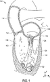
図1を最初に参照して、心臓の解剖学的構造、特に心臓の左側が記載されている。心臓104の左側は、左心房108および左心室112を含む。大動脈114は、大動脈弁120を通じて左心室112から血液を受け、この大動脈弁120は、血液が左心室112へと逆流することを防止するために働く。僧帽弁116は、左心房108と左心室112との間に位置し、そして左心房108と左心室112との間の血流を効果的に制御する。
Referring initially to FIG. 1, the anatomy of the heart, particularly the left side of the heart, is described. The left side of the
僧帽弁116(これは、図2aに関して、以下でより詳細に記載される)は、僧帽弁116の小尖が見境なく開くことを防止する「張力部材」として働く腱索124に連結される、前尖および後尖を含む。左心室112が収縮する場合、腱索124は、前尖を、その動きが腱索124によって制限されるまで、上方に向けて開かせる。通常、開口部の上方の制限は、前尖と後尖との接触部および逆流の防止に対応する。腱索124は、肉柱128から、より具体的には肉柱128の乳頭筋から生じる。
The mitral valve 116 (which will be described in more detail below with respect to FIG. 2a) is coupled to a
左心室112は、左心室112の壁134に付随した結合組織の繊維性の索である小柱132を含む。小柱132はまた、心臓104の右心室(示さず)から左心室112を隔てる心室中隔136に付随する。小柱132は、一般に、左心室112中の肉柱128の下に位置する。
The
図2aは、僧帽弁116および大動脈弁120の切り取り上部透視図である。大動脈弁120は、繊維性物質の骨格208aによって取り囲まれる弁壁204を有する。骨格208aは、一般に、大動脈弁120の周りの環を効果的に形成する繊維性構造とみなされ得る。骨格208aと実質的に同じ型構造である繊維性環208bは、僧帽弁116の周りに広がる。僧帽弁116は、上記のように、前尖212および後尖216を備える。前尖212および後尖216は、一般に、薄く柔軟な膜である。僧帽弁116が閉じている場合(図2aに示されるように)、前尖212および後尖216は、一般に、互いに整列して接触し、密封を形成する。あるいは、僧帽弁116が開いている場合、血液は、前尖212と後尖216との間に形成された開口部を通って流れ得る。
FIG. 2 a is a cutaway top perspective view of the
僧帽弁116に関する多くの問題が生じ得、これらの機能不全は、多くの型の病気を引き起こし得る。このような問題としては、僧帽弁逆流が挙げられるが、これに限定されない。僧帽弁逆流または漏出は、僧帽弁116の不完全な閉鎖に起因する左心室112から左心室108への血液の逆流である。すなわち、漏出は、間隙が前尖212と後尖216との間に形成される場合にしばしば生じる。
Many problems with the
一般に、比較的有意な間隙が、種々の異なる理由のために、(図2bに示されるように)前尖212と後尖216との間に存在し得る。例えば、間隙は、先天奇形に起因して、虚血疾患に起因して、または心臓が以前の心臓発作によって損傷を受けているために、存在し得る。間隙はまた、先天的心不全(例えば、心筋症)またはいくつかの他の型の苦痛が、心臓の拡張を引き起こす場合にも生じ得る。心臓が拡張される場合、心臓壁(例えば、左心室の壁134)は、伸びるかまたは拡張して、後尖216の伸びを引き起こし得る。前尖212は、一般に伸びないことが理解されるべきである。図2bに示されるように、前尖212と伸びた後尖216’との間の間隙220は、壁134’が伸びた場合に作成される。従って、間隙220の存在に起因して、僧帽弁116は、適切に閉じることができず、漏れ始め得る。
In general, a relatively significant gap may exist between the
僧帽弁116を通る漏出は、一般に、心臓をあまり効果的に作動させなくするので、心臓は、心臓を通る適切な量の血流を維持するためにより激しくはたらかなければならない。僧帽弁116を通る漏出、または一般な僧帽弁機能不全は、しばしば、CHFへの前駆状態とみなされる。一般に、心不全に関連する異なるレベルの症状が存在する。このようなレベルは、New York Heart Association(NYHA)の基本的分類システムによって分類されている。このレベルは、クラス1レベル(これは、身体的制限を実質的に有さない無症状の患者に関するレベルである)からクラス4レベル(これは、いずれの身体活動をも不快感なく行うことができず、そして安静時にさえ心不全の症状を有する患者に関するレベルである)までの範囲である。一般に、僧帽弁漏出についての矯正は、患者のNYHA分類の等級を低下させることを可能にすることにおいて成功し得る。例えば、クラス4分類を有する患者は、その分類をクラス3へと低下させ得、従って、安静時に比較的快適であり得る。
Because leakage through the
僧帽弁漏出またはより具体的にはCHFについて矯正するために使用される処置は、代表的には高度に侵襲性の心臓開放外科手順である。心室補助デバイス(例えば、人工心臓)は、心臓に欠陥がある患者に移植され得る。心室補助デバイスの移植は、しばしば費用がかかり、そして心室補助デバイスを有する患者は、延長された抗凝固治療を受けなければならない。当業者に理解されるように、抗凝固治療は、例えば、心室補助デバイス内に、血餅が形成される危険性を低減する。心室補助デバイスに伴う血栓の危険性を減少させることは所望であるが、抗凝固治療は、患者における、望まれない制御不能な出血(例えば、落下の結果としての)の危険性を増大させ得る。 The procedure used to correct for mitral valve leakage or more specifically CHF is typically a highly invasive open heart surgical procedure. A ventricular assist device (eg, an artificial heart) can be implanted in a patient with a defective heart. Implantation of ventricular assist devices is often expensive and patients with ventricular assist devices must receive extended anticoagulant therapy. As will be appreciated by those skilled in the art, anticoagulant therapy reduces the risk of clots forming, for example, in ventricular assist devices. While it is desirable to reduce the risk of blood clots associated with ventricular assist devices, anticoagulant therapy can increase the risk of unwanted uncontrollable bleeding (eg, as a result of a fall) in a patient .
心室補助デバイスを移植するのではなく、ペースメーカーに類似する二心室ペーシングデバイスが、いくつかの場合(例えば、特定の非同調様式で心臓が非効果的に拍動する場合)に移植され得る。二心室ペーシングデバイスの移植は、有効であり得るが、全ての心臓患者が二心室ペーシングデバイスを受容するのに適切であるわけではない。さらに、二心室ペーシングデバイスの移植は、高価である。 Rather than implanting a ventricular assist device, a biventricular pacing device similar to a pacemaker can be implanted in some cases (eg, when the heart beats ineffectively in a particular asynchronous manner). Although implantation of a biventricular pacing device can be effective, not all heart patients are suitable for receiving a biventricular pacing device. Furthermore, implantation of biventricular pacing devices is expensive.
僧帽弁漏出を矯正するために意図される開放心臓外科手順は、特に、置換弁の移植を含む。動物(例えば、ブタ)由来の弁は、ヒトにおいて僧帽弁116を置換するために使用され得る。ブタの弁の使用は、比較的首尾よく僧帽弁を置換し得るが、このような弁は、一般に消耗し、それによって後日にさらなる開放手術を必要とする。あまり消耗しなさそうな機械弁もまた、漏出性僧帽弁を置換するために使用され得る。しかし、機械弁が移植される場合、血栓塞栓症の危険性が増大し、そして患者は一般に、延長した抗凝固治療を受ける必要がある。
Open heart surgical procedures intended to correct mitral valve leakage include, in particular, replacement valve implantation. Valves from animals (eg, pigs) can be used to replace
侵襲性の少ない外科手術手順は、ポートアクセス手順に関連する心臓バイパス外科手術を含む。ポートアクセス手順について、心臓は、患者の胸全体を開胸することとは対照的に、少数の肋骨を切断することによってアクセスされ得る。言い換えれば、患者の胸骨を開口するのではなくて、少数の肋骨が、ポートアクセス手順で切断され得る。 Less invasive surgical procedures include cardiac bypass surgery associated with port access procedures. For port access procedures, the heart can be accessed by cutting a few ribs as opposed to opening the entire patient's chest. In other words, rather than opening the patient's sternum, a few ribs can be cut with a port access procedure.
僧帽弁漏出、さらに僧帽弁逆流の矯正において特に成功している1つの開放心臓外科手術手順は、輪状形成手順である。輪状形成手順の間に、弁形成リングを僧帽弁に移植して、伸縮した僧帽弁116のサイズが相対的に正常なサイズまで減少されるようにし得る。図3は、弁形成リングの略図である。弁形成リング304は、ほぼ正常な僧帽弁の外形のように成形される。すなわち、弁形成リング304は、実質的に文字「D」のように成形される。代表的には、弁形成リング304は、生体適合材料(例えば、プラスチック)(これは、DACRON網状被膜(mesh covering)を有する)のロッドまたは管から形成され得る。
One open heart surgical procedure that has been particularly successful in correcting mitral valve leakage and mitral regurgitation is an annuloplasty procedure. During the annuloplasty procedure, an annuloplasty ring may be implanted into the mitral valve so that the size of the stretched
弁成形リング304を移植するために、外科医は、僧帽弁の心房側上の僧帽弁に、弁成形リング304を外科的に装着する。リング304を導入するための従来の方法は、患者の胸骨を開口して、患者に心臓バイパス機を設置することを伴う開放心臓外科手術を必要とする。図4中に示されるように、弁成形304は、僧帽弁316の頂上部分の後尖318および前尖320に縫合される。僧帽弁316上に弁成形リング304を縫合する際に、外科医は、一般的に、針および糸を使用して僧帽弁組織から比較的大量の組織(例えば、組織の1/8インチのバイト)を、続いて、弁成形リング304からより小さいバイトを交互に獲得する。一旦糸が弁成形リング304と僧帽弁組織とを緩く連結させると、弁成形304は、僧帽弁316上に滑り、その結果、以前に(うっ積した心臓に起因して)伸びた組織は、例えば、弁成形リング304、および弁成形リング304を僧帽弁組織に結合させる糸により加えられる張力を使用して、効率的に引っ張られる。結果として、前尖320と後尖318との間の間隙(例えば、図2bの間隙220)は、実質的に閉鎖され得る。僧帽弁がリング304によって成形される後、前尖320および後尖318は、新しい接触線(contact line)を作製するように再形成して、そして、僧帽弁318が正常な僧帽弁のように見え、そして、そのように機能することを可能にする。
To implant the
一旦移植されると、組織は、一般に、弁成形リング304を超えて増殖して、弁成形リング304と僧乏弁16との間の接触線は、本質的に、僧帽弁316が正常な僧帽弁のように見え、そしてそのように機能することを可能にする。弁成形リング304を収容する患者は、抗凝固性治療に供され得るが、患者およそ数週間(例えば、組織が、弁成形リング304を超えて増殖するまで)、治療に供されるのみであるので、治療は、大規模ではない。
Once implanted, the tissue generally grows beyond the
僧帽弁漏出を減少させる際に一般的に有効である第2の外科手術手順は、僧帽弁中の単一の縁から縁への縫合を配置することを伴う。図5aを参照にして、このような外科手術手順(例えば、Alfieriステッチ手順またはボウタイ修復手順)が記載される。縁から縁へのステッチ404は、僧帽弁416の前尖420と後尖418との間で規定された間隙408のほぼ中心で領域を一緒にステッチするために使用される。一旦ステッチ404が所定の位置でなされると、ステッチ404は、示されるように、後尖418に対して前尖420を保持する縫合を形成するために引っ張られる。間隙408のサイズを減少させることで、僧帽弁416を通った漏出の量は、実質的に減少され得る。
A second surgical procedure that is generally effective in reducing mitral valve leakage involves placing a single edge-to-edge suture in the mitral valve. With reference to FIG. 5a, such a surgical procedure (eg, Alfieri stitch procedure or bowtie repair procedure) will be described. Edge-to-
縁から縁へのステッチ404の配置は、一般的に、間隙408を通った僧帽弁漏出の量を減少させることに成功するが、縁から縁へのステッチ404は、慣習的に、開放心臓外科手術を介してなされる。さらに、縁から縁へのステッチ404の使用は、一般的に、うっ積して拡張した心臓を有する患者に適切でない。なぜならば、血圧が心臓を外向きに拡張させて、縁から縁へのステッチ404対して比較的多量のストレスを及ぼし得るからである。例えば、約120/80またはそれより高い血圧は、代表的に、縁から縁へのステッチ404が、破壊したかまたは僧帽弁組織を裂く程度まで心臓を外側に拡張させるのに、十分である。
While the edge-to-
僧帽弁漏出を減少させる別の外科手術手順は、後尖の周囲の僧帽弁環に沿って縫合を配置することを伴う。僧帽弁に沿って縫合を配置する外科手術手順が、図5bに関して記載される。縫合504は、僧帽弁516の後尖518の周囲の僧帽弁516の環540に沿って形成され、そして、縫合材料の単一のストランドからダブルトラックとして(例えば、2つの「列」で)形成され得る。縫合504は、後尖518のほぼ中央の点506にて結紮される。綿球546は、しばしば、(例えば、中央の点506にて)選択された縫合504の下に位置付けられ、縫合504が環540を介して裂けるのを予防する。縫合504が結紮される場合、環540は、所望のサイズに効果的に締められ得、その結果、後尖518と前尖520との間の間隙508のサイズは減少され得る。
Another surgical procedure that reduces mitral valve leakage involves placing a suture along the mitral valve ring around the posterior leaflet. A surgical procedure for placing a suture along the mitral valve is described with respect to FIG. The
縫合504を締めることに加えて、環540に沿った縫合504の配置は、一般に、僧帽弁漏出を減少させることに成功する。しかし、構造504の配置は、慣習的に、開放心臓外科手術手順を介して達成される。すなわち、他の従来の手順と同様に、縫合ベースの輪状形成手順は、侵襲的である。
In addition to tightening the
侵襲性外科手術手順が、僧帽弁漏出の処置に効果的であることが証明されている一方で、侵襲性外科手術手順は、しばしば、重要な欠点を有する。患者が開放心臓外科手術を受けるときはいつでも、感染の危険がある。胸骨を切断して、心肺バイパス機を使用することはまた、短期神経欠損および長期神経欠損の両方の顕著な発生を生じることが示されている。さらに、開放心臓外科手術の複雑さおよび付随する大幅な回復時間を考えると、CHF症候群によって極度に不自由ではない人々(例えば、クラス1分類の人々)は、矯正外科手術を受けないように選択され得る。さらに、開放心臓外科手術が最も必要な人々(例えば、クラス4分類の人々)は、痩せすぎか、または衰弱しすぎてのいずれかで外科手術を受けられ得ない。従って、外科手術的に修復されている僧帽弁により改善され得る多くの人々は、外科手術を受けられ得ない。 While invasive surgical procedures have proven effective in the treatment of mitral valve leakage, invasive surgical procedures often have significant drawbacks. Whenever a patient undergoes open heart surgery, there is a risk of infection. Cutting the sternum and using a cardiopulmonary bypass machine has also been shown to produce significant occurrences of both short-term and long-term neurological deficits. In addition, given the complexity of open heart surgery and the associated significant recovery time, people who are not extremely crippled by CHF syndrome (eg, those in the Class 1 category) choose not to undergo corrective surgery Can be done. In addition, people most in need of open heart surgery (eg, those in the Class 4 category) cannot be operated on either because they are too thin or too weak. Thus, many people who can be improved with a mitral valve that has been surgically repaired cannot undergo surgery.
従って、必要とされることは、僧帽弁漏出のための最小限の侵襲性処置である。詳細には、所望されることは、従来の外科手術侵襲を必要としない、僧帽弁の前尖と後尖との間の漏出を減少する方法である。 Therefore, what is needed is a minimally invasive procedure for mitral valve leakage. In particular, what is desired is a method of reducing leakage between the mitral anterior and posterior leaflets that does not require conventional surgical invasion.
(発明の要旨)
本発明は、輪状形成を実施する非侵襲性の方法に関する。本発明の1つの局面に従って、輪状形成を実施するための方法は、心臓の左心室にアクセスしてこの左心室に別個のひだ形成要素(discrete plication element)を提供する工程、およびこのひだ形成要素を心臓の僧帽弁付近の組織に係合する工程を包含する。ひだ形成要素を係合する工程は、このひだ形成要素を、組織の一部を集めてひだを作製する工程を包含する。1つの実施形態において、心臓の左心室にアクセスしてひだ形成要素を提供する工程は、カテーテル配置を使用して、この心臓の左心室にアクセスする工程を包含する。
(Summary of the Invention)
The present invention relates to a non-invasive method for performing annuloplasty. In accordance with one aspect of the present invention, a method for performing annuloplasty includes accessing a left ventricle of the heart and providing a discrete pleat formation element to the left ventricle, and the pleat formation element. Engaging the tissue near the mitral valve of the heart. Engaging the pleating element includes gathering a portion of the tissue to create the pleat. In one embodiment, accessing the left ventricle of the heart to provide a plication element includes accessing the left ventricle of the heart using a catheter placement.
別の実施形態において、ひだ形成要素を僧帽弁付近の組織に係合する工程は、このひだ形成要素を使用して組織を穿刺する工程を包含し、このことで、このひだ形成要素の第1の部分は、僧帽弁の心房側上に位置付けられ、そして、ひだ形成要素の第2の部分は、僧帽弁の心室側上に位置付けられる。このような実施形態において、送達カテーテルは、このひだ形成要素の第1の部分が僧帽弁の心房側上に位置付けられるように配置され得る。 In another embodiment, engaging the plication element with tissue near the mitral valve includes puncturing the tissue using the plication element, whereby the plication element's first step. One portion is positioned on the atrial side of the mitral valve and the second portion of the plication element is positioned on the ventricular side of the mitral valve. In such an embodiment, the delivery catheter may be positioned such that the first portion of the plication element is positioned on the atrial side of the mitral valve.
例えばカテーテルを使用して、心臓の左心室にアクセスすることで、僧帽弁上で輪状形成を実施することは、僧帽弁漏出を処置する場合に、複雑な外科手術手順を回避するのを可能にする。開放心臓外科手術手順を回避することによって、一般的に、輪状形成により改善され得る患者は、輪状形成をより利用しやすくなる。僧帽弁漏出は、しばしばうっ血性心不全の初期徴候と見なされるので、漏出問題を矯正する最小の侵襲性輪状形成手順(例えば、僧帽弁周囲の線維組織における別個のひだ形成を位置付けることに関する手順)は、侵襲性輪状形成手順に適し得ない多くの患者の生活の質を非常に改善し得る。 Performing an annuloplasty on the mitral valve, for example using a catheter to access the left ventricle of the heart, avoids complex surgical procedures when treating mitral valve leakage. enable. By avoiding open heart surgical procedures, patients who can generally be improved by annuloplasty become more accessible to annuloplasty. Because mitral valve leakage is often considered an early sign of congestive heart failure, a minimally invasive annuloplasty procedure that corrects the leakage problem (eg, a procedure involving positioning separate plications in the fibrous tissue around the mitral valve) ) Can greatly improve the quality of life of many patients who may not be suitable for invasive annuloplasty procedures.
本発明の別の局面に従って、輪状形成を実施するための方法は、心臓の僧帽弁付近に位置する組織にアクセスする工程、および第1のひだ形成要素を使用して組織中で第1の別個のひだ形成を作製する工程を包含する。この第1の別個のひだ形成は、僧帽弁のアーク長が、この僧帽弁の周囲の環のサイズを効果的に縮めることによって減少されるのを引き起こす。1つの実施形態において、組織にアクセスする工程は、カテーテルを使用して心臓の左心室を通って組織にアクセスする工程を包含する。このような実施形態において、第1のひだ形成要素は、カテーテルを介して提供され得る。 In accordance with another aspect of the present invention, a method for performing annuloplasty includes a step of accessing tissue located near a mitral valve of a heart and a first in tissue using a first plication element. Creating a separate pleat formation. This first separate pleat formation causes the mitral valve arc length to be reduced by effectively reducing the size of the ring around the mitral valve. In one embodiment, accessing the tissue includes accessing the tissue through the left ventricle of the heart using a catheter. In such embodiments, the first plication element can be provided via a catheter.
他の実施形態において、第1のひだ形成要素は、クリップ要素、ロッキング要素またはバー部分、糸およびロックを含む要素であり得る。糸は、一般に、張力要素、可撓性張力要素、または縫合であり得る。クリップ要素を使用して組織中で第1の別個のひだ形成を作製する工程は、このクリップ要素を使用して組織を係合する工程を包含する。第1のひだ形成要素がロッキング要素(例えば、2つの部分を含むロッキング要素)である場合、第1の別個のひだ形成を作製する工程は、第1の部分の一部および第2の部分の一部を使用して組織を貫入する工程および第1の部分と第2の部分との間に組織を係合する工程を包含する。あるいは、第1のひだ形成要素がバー部分、糸およびロックを含む場合、第1の別個のひだ形成を作製する工程は、組織の心房側上のバー部分を位置付けるためにこの組織を貫入する工程、組織の心房側に対してバー部分を位置付けるために糸を貫通させる工程、および、バー部分とロックとの間に第1の別個のひだ形成を作製するためにこの組織の心室側に対してロックをロックする工程を包含する。 In other embodiments, the first pleating element can be an element including a clip element, a locking element or bar portion, a thread and a lock. The thread can generally be a tension element, a flexible tension element, or a suture. Creating a first discrete pleat formation in the tissue using the clip element includes engaging the tissue using the clip element. If the first pleat forming element is a locking element (eg, a locking element comprising two parts), the step of creating the first separate pleat formation may comprise a portion of the first part and a part of the second part. Using a portion to penetrate the tissue and engaging the tissue between the first and second portions. Alternatively, if the first pleat forming element includes a bar portion, a thread and a lock, creating the first separate pleat formation includes penetrating the tissue to position the bar portion on the atrial side of the tissue. Piercing the thread to position the bar portion relative to the atrial side of the tissue, and against the ventricular side of the tissue to create a first separate pleat between the bar portion and the lock. Locking the lock.
本発明のなお別の局面に従って、輪状形成手順での使用に適切なシステムは、カテーテルアセンブリおよび可屈曲部材を備える。このカテーテルアセンブリは、心臓の大動脈から心臓の左心室への挿入のために配置され、僧帽弁の実質的に下の左心室領域に達し、そして、可屈曲部材は、カテーテルアセンブリを通って左心室への挿入のための第1の位置と第2の位置の間で移動可能である。可屈曲部材はまた、第2の位置にある場合、僧帽弁付近の組織においてひだを作製するように配置される。 In accordance with yet another aspect of the present invention, a system suitable for use in an annuloplasty procedure comprises a catheter assembly and a bendable member. The catheter assembly is positioned for insertion from the aorta of the heart into the left ventricle of the heart, reaching the left ventricular region substantially below the mitral valve, and the bendable member is left through the catheter assembly. Moveable between a first position and a second position for insertion into the ventricle. The bendable member is also positioned to create a fold in the tissue near the mitral valve when in the second position.
本発明のさらに別の局面に従って、輪状形成手順における使用に適したシステムは、カテーテルアセンブリおよび縫合構造を備える。このカテーテルアセンブリは、心臓の大動脈から心臓の左心室までの挿入のために配置され、僧帽弁の実質的に下の左心室の領域に達する。縫合構造は、第1のバー部材、第2のバー部材、糸およびロック要素を備え、このロック要素は、糸を超えて移動するかまたは滑る。カテーテルアセンブリはさらに、第1のバー部材および第2のバー部材が僧帽弁付近の組織に貫入するように、そして、ロック要素が、この僧帽弁の心室側上の組織と接触するように糸を超えて移動するように配置される。ひだ形成は、実質的に、第1のバー部材、第2のバー部材およびロック要素との間の組織で作製される。 In accordance with yet another aspect of the present invention, a system suitable for use in an annuloplasty procedure comprises a catheter assembly and a suture structure. The catheter assembly is positioned for insertion from the heart aorta to the left ventricle of the heart and reaches the region of the left ventricle substantially below the mitral valve. The suturing structure comprises a first bar member, a second bar member, a thread and a locking element that moves or slides over the thread. The catheter assembly is further configured so that the first bar member and the second bar member penetrate tissue near the mitral valve and the locking element contacts tissue on the ventricular side of the mitral valve. It is arranged to move beyond the yarn. The pleat formation is made essentially of tissue between the first bar member, the second bar member and the locking element.
本発明の別の局面に従って、心臓の僧帽弁上で輪状形成を行うためのシステムは、カテーテルアセンブリ、ガイド要素およびひだ形成要素を備える。カテーテルアセンブリは、心臓の大動脈を通って心臓の左心室への挿入のために配置されて、僧帽弁の実質的に下の左心室の領域に達する。ガイド要素は、カテーテルアセンブリへの挿入のために成形され、そして、ひだ形成要素は、カテーテルアセンブリを使用してガイド要素を超えて、実質的に僧帽弁の下の左心室への挿入のために形成される。このひだ形成要素は、心臓の組織を集めてこの組織中にひだ形成を作製するために配置される。 In accordance with another aspect of the present invention, a system for performing annuloplasty on a mitral valve of a heart includes a catheter assembly, a guide element, and a plication element. The catheter assembly is positioned for insertion into the left ventricle of the heart through the aorta of the heart and reaches the region of the left ventricle substantially below the mitral valve. The guide element is shaped for insertion into the catheter assembly, and the plication element is beyond the guide element using the catheter assembly, substantially for insertion into the left ventricle under the mitral valve Formed. The plication elements are arranged to collect heart tissue and create plications in the tissue.
本発明のこれらの利点および他の利点は、以下の詳細な説明を読解して、図面の様々な図を研究することで理解される。 These and other advantages of the present invention will be understood by reading the following detailed description and studying the various figures of the drawings.
本発明は、添付の図面とともに以下の説明を参照することによって最も良く理解され得る。 The invention may best be understood by referring to the following description in conjunction with the accompanying drawings.
(実施形態の詳細な説明)
侵襲性の開放心臓外科手術は、一般的に僧帽弁漏出の処置において効果的である。しかし、開放心臓外科手術は、幾人かの患者(例えば、非常に不健康であるとみなされる虚弱な患者)にとって特に有害となり得、そして他の患者(例えば、無症候性の患者および外科的手順の実施を望まない患者)にとって所望され得ない。従って、僧帽弁の漏出またはより一般的な僧帽弁不全を矯正するための開放心臓外科手術は、僧帽弁漏出を減少させるか、または排除することより改善される可能性のあるを得る多くの患者にとって適切ではない。
(Detailed description of embodiment)
Invasive open heart surgery is generally effective in the treatment of mitral valve leakage. However, open heart surgery can be particularly harmful to some patients (eg, fragile patients that are considered very unhealthy) and other patients (eg, asymptomatic patients and surgical procedures). May not be desirable for patients who do not want to perform Thus, open heart surgery to correct mitral valve leakage or more common mitral valve failure would potentially be improved by reducing or eliminating mitral valve leakage Not suitable for many patients.
カテーテルベースの輪状形成手順は、患者が心臓切開外科手術を受けることも、心肺バイパスを配置されることも必要とせずに、患者において輪状形成を実施し得る。カテーテルは、ガイドワイヤおよびひだ形成移植物を僧帽弁の心室側(すなわち、僧帽弁の下)に位置付けるために、大動脈を通って心臓の左心室内に挿入され得る。またカテーテルを用いて、ひだ形成移植物を、僧帽弁周囲の心臓の骨格と結合している線維組織に連結し得る。 A catheter-based annuloplasty procedure can perform annuloplasty in a patient without requiring the patient to undergo open-heart surgery or a cardiopulmonary bypass. The catheter can be inserted through the aorta and into the left ventricle of the heart to position the guidewire and plication implants on the ventricular side of the mitral valve (ie, below the mitral valve). A catheter may also be used to connect the plication implant to the fibrous tissue associated with the heart skeleton around the mitral valve.
送達することおよびひだ形成挿入物またはひだ形成構造体を係合することにより、輪状形成手順を実行するためのカテーテルの使用は、心臓切開を伴わずに、かつバイパス手順を伴わずに輪状形成手順が実行されることを可能にする。輪状形成に関連する回復時間、および輪状形成に付随する危険は、輪状形成がカテーテルベースの場合に、実質的に最小になり得る。結果として、輪状形成はよりアクセス可能な手順となる。なぜなら、僧帽弁漏出に対する処置を今までに受けていない多くの患者(例えば、虚弱な患者および無症候性の患者)は、カテーテルベースの輪状形成の実施を選択し得るからである。 The use of a catheter to perform an annuloplasty procedure by delivering and engaging a pleat insert or plication structure is not involved in an angiotomy and without a bypass procedure. Allows to be executed. The recovery time associated with annuloplasty and the risks associated with annuloplasty can be substantially minimized when the annuloplasty is catheter based. As a result, ring formation is a more accessible procedure. This is because many patients (e.g., weak and asymptomatic patients) who have not previously been treated for mitral valve leakage may choose to perform a catheter-based annuloplasty.
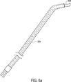
カテーテルベースの輪状形成手順を始めるために、送達管およびJ字型カテーテルは、大動脈を通って心臓の左心室内に挿入され得る。大動脈を通る送達管およびJ字型カテーテルの挿入は、心臓の左心室が柵状織または腱索(cordae tendonae)と接触することなく、左心室内に実質的に到達されることを可能にする。図6aは、本発明の実施形態に従う図式的な送達管およびJ字型カテーテルの概略図である。送達管604は実質的に環状の断面を有し、そしてJ字型カテーテル608を受け取るように構成される。必要ならば、J字型カテーテル608は、送達管604を通って長軸方向に移動させるためにアレンジされ、送達管604において開口される。
To begin the catheter-based annuloplasty procedure, the delivery tube and J-shaped catheter can be inserted through the aorta and into the left ventricle of the heart. Insertion of a delivery tube and J-shaped catheter through the aorta allows the left ventricle of the heart to be substantially reached into the left ventricle without contact with the palisade or chordae tendonae . FIG. 6a is a schematic illustration of a schematic delivery tube and J-shaped catheter according to an embodiment of the present invention.
一般的に、送達管604は細長の本体であり、これは、可撓性で、耐久性で、生体適合性の、例えば、ナイロン、ウレタンまたはナイロンとウレタンのブレンド(例えば、PEBAX(登録商標))から形成され得る。同様に、J字型カテーテル608(これもまた、細長本体である)はまた、生体適合性材料から形成され得る。J字型カテーテル608を形成するために使用される材料はまた、代表的に、比較的可撓性である。記載される実施形態において、J字型カテーテル608の上部は、J字型カテーテル608の先端部が比較的湾曲した形状(例えば、「J」字型)を維持するのを可能にするために十分剛体である。図7a〜7cについて以下に記載されるように、J字型カテーテル608の湾曲は、溝カテーテルの位置決めを容易にするように構成される。
In general,
図6bは、本発明の実施形態に従って心臓内で位置決めされた、送達管604およびJ字型カテーテル608の概略図である。示されるように、送達管604およびJ字型カテーテル608が大腿動脈を通って効果的に「蛇行」または挿入された後に、送達管604およびJ字型カテーテル608の位置は、心臓616の大動脈620内で位置決めされる。J字型カテーテル608の先端626(これは、J字型カテーテル608の本体から実質的に直角に配向している)および送達管604の端部は、これらが大動脈弁630を通過するように配向される。従って、送達管604の端部および先端626は、左心室624の頂部に位置決めされ、この位置では、左心室624の壁632は比較的平滑である。左心室624の頂部が比較的平滑であることにより、カテーテルは、壁632に沿ってカテーテルの先端を案内することによって、左心室624内で適切に位置決めされることが可能になる。1つの実施形態において、先端626は、僧帽弁628の心室側で、僧帽弁628のおよそすぐ下に位置決めされるように、配向される。
FIG. 6b is a schematic illustration of a
一旦、左心室624内で位置決めされると、J字型カテーテル608は、送達管604内で回転され得、その結果、先端626は、そこを通して供給される溝カテーテルが壁632の輪郭に沿うことを可能にし得る。代表的に、溝カテーテルは、乳頭筋640に関する平面、僧帽弁628の後尖に関する平面、腱索642、および壁632の間に効果的に規定される領域で、壁632の輪郭に沿って延びる。「溝」は、このような領域(area)または領域(region)に位置し、そしてより具体的には、比較的わずかな量の小柱が存在する、僧帽弁628の実質的に右下に位置する。
Once positioned within the
図7a〜7cを参照して、溝カテーテルが、本発明の実施形態に従って記載される。溝カテーテル704(これは、図7aに示されるように、カテーテルアセンブリ702の一部である)は、J字型カテーテル626を通って延びるように配置され、その結果、溝カテーテル704は、僧帽弁のすぐ下の左心室内に進められ得る。バルーン先端(図示せず)を備え得る溝カテーテル704は、代表的に、ナイロン、ウレタン、またはPEBAX(登録商標)のような、可撓性の材料から形成される。1つの実施形態において、操縦可能である溝カテーテル740は、形状記憶金属を使用して形成され得る。
With reference to FIGS. 7a-7c, a groove catheter is described in accordance with an embodiment of the present invention. Groove catheter 704 (which is part of
図7aおよび図7b(これらは、位置710においてとったカテーテルアセンブリ702の断面を表す)に示されるように、溝カテーテル704は、少なくとも部分的に、J字型カテーテル608の内部に位置決めされ、このJ字型カテーテルは、次に、送達管604内に少なくとも部分的に位置決めされる。溝カテーテル704は、J字型カテーテル608の内部で自由に回転し得、そしてJ字型カテーテル608を通って延び得、一方でJ字型カテーテル608は、送達管604の内部で自由に回転し得、そして送達管604を通って延び得る。
As shown in FIGS. 7a and 7b (which represent a cross section of the
次に、図7cを参照して、心臓の左心室内での溝カテーテル704の位置決めが、本発明の実施形態に従って記載される。説明を簡単にし、そして議論を簡単にするために、左心室720内での溝カテーテル704の表現は、同一縮尺では描かれていないことが、理解されるべきである。例えば、左心室720の壁724と僧帽弁728との間の距離は、誇張されている。さらに、大動脈弁732内での送達管604の位置決め、ならびに従って、J字型カテーテル608および溝カテーテル704の位置決めが変動し得ることもまた、理解されるべきである。
Referring now to FIG. 7c, positioning of the
溝カテーテル704は、J字型カテーテル608の先端626を通って突出し、そして操縦によって、僧帽弁728のすぐ下の左心室720の壁724の輪郭に沿って(すなわち、左心室720の溝に沿って)、僧帽弁728の円弧形状と類似の円弧形状を、実質的に形成する。左心室720の壁724は、僧帽弁728のすぐ下において、比較的平滑である(すなわち、一般的に小柱を含まない)。従って、大動脈弁732を通して左心室720の上部にカテーテルアセンブリ702を挿入することによって、溝カテーテル704は、実質的に小柱または腱索によって閉塞されることなく、壁724に沿って僧帽弁720内で誘導されることが可能になる。
溝カテーテル704は、一般に、開口部または管腔(図示せず)を備え、これは、ガイドワイヤを収容するような大きさにされ、ここを通してガイドワイヤが挿入され得る。この開口部は、溝カテーテル704の中心軸(すなわち、図7aに示されるような中心軸730)に沿って位置し得る。溝カテーテル704を通してガイドワイヤを送達することによって、ガイドワイヤが壁724の輪郭に効果的に従うことが可能となる。一般に、ガイドワイヤは、係留先端を備え、これは、ガイドワイヤが壁724に実質的に係留されることを可能にする。図8は、ガイドワイヤが本発明の実施形態に従って位置決めされた、心臓の左側の図式的な切取り上面図である。議論を簡単にするために、図8における心臓の左側の表現は、同一縮尺では描かれていないこと、および種々の特徴が誇張されていることが、理解されるべきである。ガイドワイヤ802は、左心室720の壁724に沿って位置決めされる。一旦、ガイドワイヤ802が図7a〜7cの溝カテーテル704を通して挿入され、そして係留先端806を使用して壁724に係留されると、溝カテーテル704は、J字型カテーテル708と共に、患者の身体から引き抜かれる。ガイドワイヤ802が壁724に係留された後は、送達管604は、代表的に、大動脈内で位置決めされたままであることが、理解されるべきである。
ガイドワイヤ802(これは、ステンレス鋼または形状記憶材料のような材料から形成され得る)は、一般に、ガイドワイヤ802が壁724の大部分に沿って効果的に通過するように、係留される。代表的に、ガイドワイヤ802は、軌道として働き、これを覆って、ひだ形成構造体を運ぶカテーテルが位置決めされ得る(すなわち、ひだ形成要素を送達するカテーテルの管腔が、ガイドワイヤ802を覆って通り得る)。このようなカテーテルは、バルーン構造体(図示せず)または膨張可能構造体を備え得、これは、実質的に、僧帽弁の周囲の線維組織に局所ひだ形成構造体を押し付けることによって、局所ひだ形成構造体の位置決めを容易にし得る。
A guide wire 802 (which can be formed from a material such as stainless steel or shape memory material) is generally anchored so that the
局所ひだを形成することによって、僧帽弁の周囲の線維組織の束が捕捉されるかまたは集められ、これによって、僧帽弁の後尖の拡張が減少される。一般に、局所ひだは、縫合構造体または不連続な機械的要素を使用して、僧帽弁の周囲の線維組織に形成される、不連続なひだである。図9aは、心臓の左心室の、上から下に見た切取り図の表現であり、ここで、局所ひだ形成縫合構造体が、本発明の実施形態に従って、移植されている。縫合構造体(これは、T字型バー904および糸907を備える)は、僧帽弁916の近くの組織(例えば、僧帽弁916の輪)に移植される。代表的に、縫合構造体が移植される組織は、僧帽弁916の実質的に周囲に位置する線維組織940である。適切な縫合構造体としては、図10a、10b、11、および12a〜cを参照して以下に記載されるような、T字型バー904および糸907を備える構造体が挙げられるが、これらに限定されない。
By forming a local pleat, a bundle of fibrous tissue around the mitral valve is captured or collected, thereby reducing dilation of the mitral valve posterior leaflet. In general, a local pleat is a discontinuous fold that is formed in the fibrous tissue around the mitral valve using a suture structure or discontinuous mechanical elements. FIG. 9a is a top-down cutaway representation of the left ventricle of the heart, where a local plication suture structure has been implanted in accordance with an embodiment of the present invention. The suture structure (which comprises a T-shaped
T字型バー904または類似の構造体は、移植される場合、組織940を切り通すので、外科用綿撤糸905は、心室側部の組織940に当たり、T字型バー904を効果的に「保護」し得る。従って、T字型バー904の一部は、僧帽弁916の上(すなわち、僧帽弁916の動脈側)に位置決めされ、一方で外科用綿撤糸905は、僧帽弁916の心室側に位置決めされる。さらなる綿撤糸または代替の綿撤糸が、僧帽弁916の動脈側に、実質的に組織940とT字型バー904との間に位置決めされ得ることが、理解されるべきである。僧帽弁916の心室側から僧帽弁916の動脈側に縫合構造体904を送達するカテーテルは、図13a〜cに関して以下に議論される。
The T-
記載される実施形態において、T字型バー904は、2つずつのT字型バー(例えば、T字形バー904a)が糸(例えば、糸907a)によって結合されるように、結合される。糸907aは、T字型バー904aが一緒に緊張し、そして組織940に対して固定され得るように、構成される。T字型バー904aを固定することによって、組織940は束ねられるかまたはわずかに集められ得、これによって、組織940に関する円弧の長さを減少させることによって、僧帽弁916の大きさ(例えば、円弧長さ)を効果的に制限する。換言すれば、糸907と協働して実質的に縫合糸として機能するT字型バー904の存在は、前尖920と後尖918との間の間隙908が減少し、そしてさらに、増加することを実質的に防止されることを可能にする。当業者によって理解されるように、時間が経つにつれて、瘢痕組織(図示せず)が、外科用綿撤糸905およびT字型バー904の周囲に形成され得る。
In the described embodiment, the T-shaped
一般に、組織940を局所的に束ねるかまたは集めるために使用されるT字型バー904の数は、広く変動し得る。例えば、実質的にほんの小さな局所的な逆流ジェットが僧帽弁916において起こる場合、ほんの少数のT字型バー904が、この逆流ジェットの近位に移植され得る。あるいは、間隙908の大きさが有意であり、そして比較的多量の僧帽弁漏出が存在する場合、比較的多数のT字型バー904および従って外科用綿撤糸905が使用され、僧帽弁916の円弧長さを減少させることによって、間隙908の大きさを減少させ得る。いくらかの外科用綿撤糸905は、少なくとも部分的に重なるように配置され得る。僧帽弁916のほんの1部分に集中する逆流ジェットを矯正するためには、T字型バー904は、逆流ジェットの近くにひだ形成要素として、そして逆流ジェットから離れた補強要素として(例えば、実質的な間隙が最終的に形成されることを僧帽弁疾患の進行が引き起こすことを予防するために)、移植され得る。
In general, the number of T-
2つのT字型バー904aを糸907aで結合することが記載されたが、糸907によって結合されるT字型バー904の数は変動し得ることが、理解されるべきである。例えば、複数のT字型バー904が複数の糸907で結合される場合、より多くの線維組織を、より少ない総数のT字型バー904で集めることが可能であり得る。図9bを参照して、複数の糸907で結合された複数のT字型バー904が記載される。T字型バー904cは、糸907cによって結合され、一方でT字型バー904dは、糸907dによって結合される。同様に、T字型バー904eは、糸907eによって結合される。T字型バー904d’は、さらに、糸907fによって、T字型バー904c”に結合され、そしてT字型バー904d”はまた、糸907gによって、T字型バー904e’に結合される。以下に議論されるように、糸907は、T字型バー904が外科用綿撤糸905および従って組織940に対して引かれることを可能にする。T字型バー904をこのように結合することによって、組織940におけるひだが、T字型バー904c間、T字型バー904d間、およびT字型バー904e間で作製され、一方で組織が、T字型バー904c”とT字型バー904d’との間、およびT字型バー904d”とT字型バー904e’との間で、少なくともいくらか集められることが可能になる。
Although it has been described that two T-
一般に、T字型バー904および糸907を備える縫合構造体の構成は、変化し得る。適切な縫合構造体の1つの実施形態が、図10aおよび10bに示される。図10aおよび10bは、T字型バーが、本発明の実施形態に従って、僧帽弁の近くの線維組織の動脈側に導入された後の、縫合構造体の表現である。説明の目的で、図10aおよび10b、ならびに実質的に全ての他の図に示される要素および構造体は、同一縮尺では描かれていないことが、理解されるべきである。縫合構造体1000は、糸907に結合されたT字型バー904(すなわち補強要素)を備え、その結果、糸907が引かれる場合、T字型バー904は、組織940に効果的に押し付けられる。図10bに示されるように、糸907を引き、そしてロッキング要素1002を押すことによって、ロッキング要素1002は、組織940の心室側に接触し、そしてT字型バー904を組織940に対して効果的に保持する。具体的には、糸907のループ1004を引き、同時にロッキング要素1002を押すことによって、T字型バー904が組織940に対して締まり、その結果、ロッキング要素1002が適所に固定されてT字型バー904を適所に固定する場合に、ひだ1006が組織940に形成され得る。
In general, the configuration of the suturing structure comprising the T-shaped
外科用綿撤糸905は、当業者によって理解されるように、T字型バー904(これは、本質的に、縫合糸として機能する)に対するひだアンカーとして働き得る。すなわち、外科用綿撤糸905は、T字型バー904が組織940を切り通すことを防止し得る。一般に、外科用綿撤糸905の構成は、広く変化し得る。例えば、外科用綿撤糸905は、実質的に管状の形状を有し得、そして外科用メッシュ(例えば、Dacronメッシュ)のような材料から形成され得る。しかし、外科用綿撤糸905は、それを通しての瘢痕組織の成長を促進または支持する、実質的に任意の形状で、そして実質的に任意の材料から形成され得ることが、理解されるべきである。適切な材料としては、絹および実質的に任意の生体適合性の多孔性または繊維性の材料が挙げられるが、これらに限定されない。
ロッキング要素1002は、生体適合性ポリマーから形成された、一方向ロッキング要素(例えば、一旦固定されると容易には固定を解除され得ない要素)であり得る。ロッキング要素1002の構成は、広く変化し得る。ロッキング要素1002の代替の構成は、図11および図12a〜cを参照して、以下に記載される。ロッキング要素1002を外科用綿撤糸905に係合させるために、T字型バー904を送達するために使用されるカテーテルが使用されて、ロッキング要素1002を固定位置に押し得る。T字型バー904を送達し、そしてまたロッキング要素1002を係合し得るカテーテルは、図13a〜cを参照して、以下に議論される。
The
ロッキング要素1002と同様に、T字型バー904もまた、生体適合性ポリマーから形成され得る。糸907(これは、T字型バー904を糸907に結ぶことによって、またはT字型バー904を糸907の上に成形することによって、T字型バー904を結合し得る)は、縫合糸を形成するために代表的に使用される実質的に任意の材料から形成され得る。適切な材料としては、絹、プロレン(prolene)、編組Dacron、およびポリテトラフルオロエチレン(PTFE、またはGoreTex)が挙げられるが、これらに限定されない。
Similar to locking
上記のように、ロッキング要素1002の構成は、変化し得る。例えば、ロッキング要素は、図11に示されるようなばね要素を備え得る。縫合構造体1100は、T字型バー1104、糸1107、およびロッキング要素1102を備える。説明を簡単にするために、縫合構造体1100の要素は、同一縮尺では描かれていない。縫合構造体1100は、外科用綿撤糸を備えるように示されていないが、縫合構造体1100は、外科用綿撤糸を備え得、これらが、瘢痕組織の成長を一般的に支持する補強要素として働くことが、理解されるべきである。
As described above, the configuration of the
ロッキング要素1102は、中実要素1102aおよびばね要素1102bを備える。中実要素1102aは、生体適合性ポリマーから形成され得るが、中実要素1102aはまた、外科用綿撤糸を形成するために代表的に使用される材料から形成され得る。ばね要素1102bは、糸1107のループ1114が引かれている間に、示されるように、伸長位置に保持されるように配置される。一旦、T字型バー1104が組織1140と接触すると、中実要素1102aは組織1140と接触し得、そしてばね要素1102bは収縮してばね力を生じ得、このばね力が、中実要素1102aを互いの方へと引く。換言すれば、一旦、T字型バー1104が組織1140に対して適切に位置決めされると、ロッキング要素1102が固定されて、組織1140のひだまたは局所的な束を形成し得る。
The locking element 1102 includes a
1つの実施形態において、僧帽弁の近位の線維組織における瘢痕組織の形成は、ひだが形成される前、または線維組織が集められて僧帽弁の不全を代償する前に、促進され得る。図12a〜cを参照して、ひだ形成の前に瘢痕組織の成長を促進するロッキング要素が、本発明の実施形態に従って記載される。図12aに示されるように、縫合構造体1200(これは、同一縮尺では描かれていない)は、ロッキング要素1204、糸1207、およびT字型バー1204を備える。ロッキング要素1204(これは、中実要素1202a、ばね要素1202b、およびばね要素1202bの上に形成された再吸収性ポリマーのオーバーモールド(overmold)1202cを備える)は、組織1240の心室側で、糸1207に結合される。
In one embodiment, the formation of scar tissue in the fibrous tissue proximal to the mitral valve can be promoted before plication is formed or before the fibrous tissue is collected to compensate for mitral valve failure. . With reference to FIGS. 12a-c, a locking element that promotes the growth of scar tissue prior to plication is described in accordance with an embodiment of the present invention. As shown in FIG. 12 a, the suturing structure 1200 (which is not drawn to scale) includes a
オーバーモールド1202c(これは、再吸収性のラクチドポリマー(例えば、Lincolnshire,IllinoisのPURAC Americaから入手可能なPURASORB)から形成され得、ばね要素1202bが伸長位置にある間に、ばね要素1202bの上に形成される。オーバーモールド1202cは、瘢痕組織1250が中実要素1202aの上に形成される間、インタクトなままであるように配置される。1つの実施形態において、瘢痕組織の形成を容易にするために、中実要素1202aは、多孔性または繊維性の材料(例えば、「外科用綿撤糸材料」)から形成され得る。
一旦、瘢痕組織が中実要素1202aの上に形成されると、オーバーモールド1202cは破壊され(例えば、分解し)、図12bに示されるように、ばね要素1202bを露出させる。当業者によって理解されるように、オーバーモールド1202cの化学組成は、オーバーモールド1202cが破壊されるまでに経過する時間の量が制御され得るように(例えば、所望の量の瘢痕組織が形成されると予測された後に分解するように)、調整され得る。従って、一旦、オーバーモールド1202cが破壊され、そして図12cに示されるようにばね要素1202bが接触されると、十分な瘢痕組織1250が、一般に、中実要素1202aの上に形成されて、中実要素1202aを組織1240に効果的に結合し、組織1240の比較的強力なひだまたはギャザーを形成することを可能にする。
Once scar tissue is formed on
糸1207のループ1214は、心臓の左心室内に延びたままにされ得るが、糸1207は、切断され(すなわち、ループ1214は、効果的に除去され)、心臓内にたるんだ糸1207の量を減少させ得る。あるいは、たるんだ糸1207は、ロッキング要素1202の上に位置する円筒形の配置(図示せず)の周りに糸1207を集めることによって、効果的に排除され得る。すなわち、スプールまたは類似の要素が、縫合構造体1200の一部として含まれて、たるんだ糸1207がスプール内に集められること、またはスプールの外側の周りに集められることのいずれかを可能にし得る。
The
オーバーモールド1202cを使用することによって、T字型バー1204およびロッキング要素1202を適所に保持する係留力を比較的低くすることが可能である。なぜなら、瘢痕組織または組織の内方発育が作製されるまでは、組織1240に対して作用する有意な力が、実質的に存在しないからである。一旦、瘢痕組織が作製され、そしてオーバーモールド1202cが分解すると、ばね1202bが圧縮する。この時点で発生する係留力は、比較的高くあり得る。しかし、瘢痕組織が形成されているので、この時点でT字型バー1204が組織1240に切り込む可能性は、一般に比較的に低い。
By using the
上記のように、縫合構造体を心臓に送達するため、および縫合構造体を心臓の僧帽弁の周囲に係合させるために、カテーテルが使用され得る。局所ひだ形成を使用する、カテーテルに基づく輪状形成術における使用に適切な、縫合構造体送達カテーテルの1つの実施形態は、図13aに関して記載される。送達カテーテル1300は、ガイドワイヤ(例えば、図8に示されるようなガイドワイヤ802)を覆って位置決めされ得、このガイドワイヤは、送達カテーテル1300が心臓の溝に送達されることを可能にする軌道として働く。送達カテーテル1302の要素は、同一縮尺では描かれていないことが、理解されるべきである。送達カテーテル1300内に、ワイヤ1308があり、これは、縫合構造体のT字型バー1304を運ぶ。1つの実施形態において、T字型バー1300は、糸1307およびロッキング要素1300に結合され、縫合構造体を形成する。代表的に、ワイヤ1308の尖った端部または鋭利な端部1311は、組織(図示せず)(例えば、僧帽弁の近くの心臓の線維組織)を穿刺するように構成される。一旦、端部1311およびT字型バー1304が線維組織の上(例えば、僧帽弁の動脈側)に位置すると、ワイヤ1308は引き込まれ、再配置され得る。ワイヤ1308が再配置された後に、端部1311は、再度、組織を穿刺して、T字型バー1304を、僧帽弁の動脈側で、組織の上に効果的に配置し得る。
As described above, a catheter can be used to deliver the suture structure to the heart and to engage the suture structure around the mitral valve of the heart. One embodiment of a suture structure delivery catheter suitable for use in catheter-based annuloplasty using local plication is described with respect to FIG. 13a. The
ワイヤ1308、またはより具体的には、端部1311は、僧帽弁の近くの組織に対して適切な位置に、糸1307を引き、そしてロッキング要素1302を押すために使用され得る。例として、端部1311は、T字型バー1304が組織に接触するまで、糸1307を引き得る。次いで、端部1311は、ロッキング要素1302を組織に対して固定し、その結果、組織にひだを作製して、僧帽弁の輪を効果的に収縮させるために、使用され得る。
The
さらなるひだを作製するために、ワイヤ1308、および1つの実施形態において、送達カテーテル1300は、患者から完全に引き抜かれて、さらなるT字型バーがワイヤ1308上に装填されることを可能にし得る。一旦、さらなるT字型バーがワイヤ1308上に位置決めされると、ワイヤ1308は、送達カテーテル1300内に再挿入され得、そして送達カテーテル1300は、別のひだが、僧帽弁の近くに位置する組織に形成されることを可能にするために、使用され得る。
To create additional pleats, the
図13bは、本発明の実施形態に従って縫合構造体を送達するために適切な、第二のカテーテルの表現である。カテーテル1340(これは、同一縮尺では描かれておらず、そしてガイドワイヤの上に挿入されるように配置された管腔(図示せず)を備え得る)は、2つのワイヤ1348を備え、これらは、協働して縫合構造体を運ぶように配置される。示されるように、ワイヤ1348aは、T字型バー1344aを運び、一方でワイヤ1348bは、T字型バー1344bを運び、これらのT字型バーは、糸1347によって結合され、そしてロッキング要素1342と一緒になって、縫合構造体を形成する。ワイヤ1348の先端1351は、僧帽弁の近くの組織を通って、T字型バー1344を僧帽弁の上に配置する。一旦、T字型バー1344が配置されると、先端1351は、T字型バー1344を組織に対して引くため、およびロッキング要素1342をこの組織の反対側に対して固定するために、使用され得る。例として、先端1351bは、先端1351aがロッキング要素1342を押し付ける間に、糸1347を引くように構成され得る。
FIG. 13b is a representation of a second catheter suitable for delivering a suture structure according to an embodiment of the present invention. Catheter 1340 (which is not drawn to scale and may include a lumen (not shown) arranged to be inserted over the guide wire) includes two
図13cを参照して、T字型バーをその先端から展開し得るカテーテル配置が、本発明の実施形態に従って記載される。カテーテル配置1360は、2つのカテーテルを備え、これらの各々が、T字型バー1364を運ぶ。図13cの要素は、説明を容易にするために、同一縮尺では描かれていないことが、理解されるべきである。具体的には、カテーテル1360aは、T字型バー1364aをその先端において運び、一方で、カテーテル1360bは、T字型バー1364bを、その先端において運ぶ。糸1367が、T字型バー1364を一緒に結合し、その結果、ロッキング要素1362(これを、糸1367が通過する)は、T字型バー1364を心臓の組織に対して実質的に固定し得る。
Referring to FIG. 13c, a catheter arrangement that can deploy a T-bar from its tip is described in accordance with an embodiment of the present invention. Catheter arrangement 1360 comprises two catheters, each of which carries a T-shaped bar 1364. It should be understood that the elements of FIG. 13c are not drawn to scale for ease of explanation. Specifically, the
1つの実施形態において、カテーテル配置1360は、カテーテル1360aおよびカテーテル1360bの各々を心臓の溝に案内するために、2つのガイドワイヤの使用を必要とし得る。あるいは、カテーテル1360aおよびカテーテル1360bは、カテーテル1360aとカテーテル1360bとの両方が、単一のガイドワイヤの使用によって、心臓の溝を通して案内され得るように、配置され得る。
In one embodiment, the catheter arrangement 1360 may require the use of two guide wires to guide each of the
カテーテル1360aは、心臓の僧帽弁の近くの組織を通してT字型バー1364aを押し、そして一旦、T字型バー1364aが僧帽弁の心室側に配置されると、T字型バー1364aを離すように構成される。同様に、カテーテル1360bは、組織を通してT字型バー1364bを押し、そしてT字型バー1364bを離すように、構成される。T字型バー1364は、例えば、熱が、カテーテル1360に付随する誘電材料に適用される場合に離され得、これにより、T字型バー1364が効果的に外れる。あるいは、T字型バー1364をカテーテル1360に係合させる機械的機構(図示せず)が脱係合されて、T字型バー1354を離し得る。一旦、T字型バー1364が僧帽弁の心室側に位置決めされると、カテーテル1360は、糸1367を引き、そしてロッキング要素1362を押すために使用され得る。
図14aおよび14bを参照して、僧帽弁の近くの組織に縫合構造体を移植する、カテーテルに基づくシステムを使用する輪状形成術の手順の実施が、本発明の実施形態に従って記載される。一旦、患者が準備されると(例えば、鎮静されると)、輪状形成術手順1400は、送達管およびJ字型カテーテルを、患者の心臓の左心室に挿入することで開始し得る。これらの送達管およびJ字型カテーテルは、大腿動脈を通して患者の身体に挿入され、そして大腿動脈および大動脈を通され、そして心臓の左心室に入り得る。一般に、J字型カテーテルは、送達管内に位置決めされる。送達管およびJ字型カテーテルの1つの実施形態は、図6aおよび6bに関して上で記載された。当業者によって理解されるように、送達管およびJ字型カテーテルは、代表的に、それぞれ、大動脈弁を通して左心室に到る。
With reference to FIGS. 14a and 14b, performing an annuloplasty procedure using a catheter-based system for implanting a suture structure in tissue near a mitral valve will be described in accordance with an embodiment of the present invention. Once the patient is prepared (eg, sedated), the
一旦、送達管およびJ字型カテーテルが左心室内で位置決めされると、工程1408において、溝カテーテルが、J字型カテーテルを通して延ばされ得る。図7a〜cに関して上で議論されたように、溝カテーテルは、僧帽弁の実質的にすぐ下の左心室の壁の溝に対して効果的に延びるように配置される。具体的には、溝カテーテルは、僧帽弁と乳頭筋(musculi papillares,or papillary muscles)との間の、左心室の空間に位置決めされ得る。溝カテーテルは、しばしば、操縦可能な可撓性の先端を有する。1つの実施形態において、溝カテーテルの先端は、膨張可能なバルーンに結合され得る。J字型カテーテルは、他の目的のうちでもとりわけ、溝カテーテルが最初に、溝カテーテルが左心室の壁に沿って位置決めされ得るような適切な方向に配向されることを可能にするように働く。
Once the delivery tube and the J-shaped catheter are positioned in the left ventricle, in
工程1412において、係留装置を備えるガイドワイヤは、溝カテーテル(gutter catheter)を通して(例えば、溝カテーテルの管腔または開口を通して)送達され得る。ガイドワイヤは、左心室の壁に対して溝ワイヤの輪郭に続くように、溝カテーテルを通して送達される。ガイドワイヤが送達された後、ガイドワイヤの係留装置は、工程1416において、左心室の壁に対して係留される。左心室の壁に対してガイドワイヤを係留すること、またはそうでなければガイドワイヤを移植することにより、ガイドワイヤが、左心室内のその位置に維持されることが可能になる。
In
J字型カテーテルおよび溝カテーテルは、図8に関して上述されたように、工程1420において、ガイドワイヤを左心室に係留したまま、大腿動脈を通して左心室から引き抜かれる。次いで、工程1436において、T字型バーアセンブリを保有するT字型バーアセンブリ送達カテーテルが、ガイドワイヤ全体にわたり、大腿動脈を通して左心室に挿入される。1つの実施形態において、T字型バーアセンブリ送達カテーテルは、未膨張バルーンを保有する。
The J-shaped catheter and the sulcus catheter are withdrawn from the left ventricle through the femoral artery in
T字型バーアセンブリ送達カテーテルが左心室に挿入された後、このバルーンは、工程1428において、膨張される。このバルーン(例えば、エラストマーバルーン)が、例えば、T字型バーアセンブリ送達カテーテルを通してバルーンに連結された空気供給源を用いて比較的穏やかな圧力で膨張されることにより、ガイドワイヤをトラックとして使用する実質的に任意のカテーテルが、僧帽弁の周囲の線維組織を押し上げることを可能にするよう作用する。一般的に、膨張したバルーンは、僧帽弁と乳頭筋との間の空間を実質的に占有する。1つの実施形態において、1つよりも多いバルーンが、左心室において膨張され得る。
After the T-bar assembly delivery catheter is inserted into the left ventricle, the balloon is inflated at
一度、工程1428において、バルーンは膨張される。T字型バーアセンブリ送達カテーテルは、T字型バーまたは類似の機構、外科用綿撒糸、および僧帽弁の輪(例えば、僧帽弁の周囲の骨の線維組織)に付着するか、そうでなければそれに連結するようにされた糸に効果的に送達し、ひだが作製される。適切なカテーテルは、図13a〜cに関して上記された。工程1440において、ひだは、僧帽弁付近の実質的に任意の適切な組織において、T字型バーアセンブリを用いて作製される。例えば、ひだは、組織を通してT字型バーを本質的に押し込み、次いで、T字型バーアセンブリの固定機構を用いてその組織に対してT字型バーを固定することにより作製され得る。詳細には、組織のひだ形成または数珠つなぎ(bunching)は、T字型バーのような要素を保有する先の尖ったワイヤを組織を通して伸ばし、次いで、その先の尖ったワイヤを引っ込め、そしてT字型バーを適所に配置することにより作製され得る。T字型バーの配置および固定機構の固定により、T字型バーと固定機構との間の組織が、一緒に数珠つなぎされ得る。
Once in
一旦、工程1440において、ひだが作製されると、バルーンは、一般的に、工程1442において収縮される。次いで、T字型バーアセンブリ送達カテーテルは、工程1444において、大腿動脈を通して除去され得る。さらなるひだが作製されるか否かに関する決定は、工程1448において、T字型バーアセンブリ送達カテーテルが除去された後になされる。さらなるひだが作製されることが決定される場合、次いで、プロセスの流れは、工程1436に戻り、T字型バーアセンブリまたは縫合構造を保有するT字型バーアセンブリ送達カテーテルが、大腿動脈に再挿入される。
Once the pleat is created at
あるいは、工程1448において、それ以上ひだが作製されないことが決定される場合、次いで、プロセスの流れは、工程1456に進み、ガイドワイヤが除去され得る。ガイドワイヤが除去された後、送達管は、工程1460において除去され得る。一旦、送達管が除去されると、輪状形成手順が完結する。
Alternatively, if it is determined at
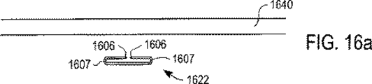
局所的なひだを作製するためにT字型バーアセンブリのような縫合構造を用いる代わりに、他の要素もまた、輪状形成手順の間に僧帽弁付近の線維組織において局所的なひだを作製するために使用され得る。図15は、本発明の実施形態に従って個々の分離した要素を用いて局所的なひだが作製された心臓の左側を示す切り抜き平面図である。局所的ひだ形成要素1522は、前尖1520と後尖1518との間の隙間1508の大きさを減少させるために(例えば、後尖1518に関連する弧の長さを減少させるために)、僧帽弁1516の部分周囲の線維組織1540に効果的に移植される。局所的ひだ形成要素1522は、組織1540の小片を集めて局所的なひだを作製するように配置されている。局所的ひだ形成要素1522(一般的に、機械的要素である)により作製される局所的なひだは、僧帽弁環の大きさを減少させ、従って、隙間1508の大きさを減少させる。当業者に理解されるように、経時的に、瘢痕組織が局所的ひだ形成要素1522の周囲またはその上で成長し得る。
Instead of using a suture structure such as a T-bar assembly to create local folds, other elements also create local folds in the fibrous tissue near the mitral valve during the annuloplasty procedure. Can be used to FIG. 15 is a cutaway plan view showing the left side of a heart that has been locally pleated with individual discrete elements in accordance with an embodiment of the present invention.
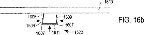
局所的ひだ形成要素1522の構成は、広範に変化し得る。例えば、局所的ひだ形成要素1522は、ばね様特性を有する金属製要素か、または形状記憶特性を有する変形可能な金属製要素であり得る。あるいは、各々の局所的ひだ形成要素1522は、物理的に一緒に固定されてひだを形成し得る別々の片から形成され得る。図16a〜dを参照すると、ばね様特性を有する局所的ひだ形成要素の1つの実施形態が、本発明の実施形態に従って記載される。局所的ひだ形成要素1622は、僧帽弁の付近に位置する組織1640の心室側または底側に送達され得る。送達される場合(例えば、カテーテルを通して)、要素1622は、図16aに示すように、実質的に折り畳まれ、閉じられる向きにある。言い換えると、要素1622は、カテーテルを通した要素1622の送達を容易にする閉じられた構成にある。初期圧縮力が、要素1622の角1607に付与された後、要素1622の端または鋭利先端1609は、折り畳まれなくなるかまたは開かれ得る。鋭利先端1609が開く場合、鋭利先端1609の端1606は、図16bに示されるように、組織1640に対して押さえ付けられ得る。鋭利先端1609への圧縮力の付与、および要素1622の底1611への押し出し力(pushing force)は、端1606(従って、鋭利先端1609)が組織1640を掴むのを可能にする。なぜならば、図16cに示されるように、先端1606が組織1640を通して押し込むからである。鋭利先端1609に付与される圧縮力に起因する鋭利先端1609の閉鎖により、組織1640が、鋭利先端1609の間に集められ、結果として、図16dに示されるように、ひだ1630が形成される。1つの実施形態において、要素1622を送達するカテーテル(示されていない)が、要素1622に力を付与するために使用され得る。
The configuration of the
上記のように、局所的なひだを作製するために使用される要素は、形状記憶材料から作製され得る。ひだ形成要素を作製するために形状記憶材料を使用することにより、このひだ形成要素が自己固定することを可能にする。図17aは、本発明の実施形態に従って形状記憶材料から形成された1つのひだ形成エレメントの図である。クリップ1704(形状記憶材料から形成され得る(すなわち、ニッケルとチタンとの合金))は、左心室の溝(gutter)に導入される(例えば、カテーテルにより)際には、拡張状態または開放状態であるように配置される。代表的に、拡張状態にある保持クリップ1704は、クリップ1704への力の付与に関与する。1つの実施形態において、カテーテルは、クリップ1704を拡張状態で維持するために、クリップ1704の側面1708を保持し得る。
As described above, the elements used to create the local folds can be made from a shape memory material. Using a shape memory material to make the pleating element allows the pleating element to self-fix. FIG. 17a is an illustration of one pleating element formed from a shape memory material in accordance with an embodiment of the present invention. Clip 1704 (which can be formed from a shape memory material (ie, an alloy of nickel and titanium)) is in an expanded or open state when introduced into a left ventricular gutter (eg, via a catheter). Arranged to be. Typically, the
一旦、先端1706が僧帽弁の心房側に位置するように、クリップ1704の先端1706が心臓の僧帽弁付近の繊維組織を通して押し込まれると、力は、クリップ1704から除去され得る。クリップ1704は、形状記憶材料から形成されるので、一旦、力が除去されると、クリップ1704は、図17bに示されるように、それ自身をその「休止」状態の形状に形成する。その休止状態または好ましい状態において、クリップ1704は、クリップ1704により規定される開口1712に組織を集めるように配置されている。すなわち、初期状態のクリップ1704は、閉じられた構成であり、局所的なひだを作製するために組織を数珠つなぎするのに有効である。
Once the
局所的なひだを作製するのに適切な、別の異なる自己固定ひだ形成エレメントは、一旦、クリップを開口位置で保持するために付与された力が除去されると、開口位置から閉鎖位置または係合位置に向かってねじれ得るクリップである。図18aは、本発明の実施形態に従って閉鎖位置で示される別の自己固定ひだ形成エレメントの図である。ステンレス鋼または形状記憶材料のような材料から形成され得るクリップエレメント1800は、一旦、組織1830が鋭利先端1806と鋭利先端(time)1808との間の隙間1810に位置されると、クリップエレメント1800が、組織1830を隙間または空間1810内で摘み取る状態に戻され得るように、予め充填される。
Another different self-locking plication element suitable for creating a local pleat is a closed or engaged position from the open position once the force applied to hold the clip in the open position is removed. The clip can be twisted toward the mating position. FIG. 18a is an illustration of another self-locking plication element shown in a closed position in accordance with an embodiment of the present invention.
鋭利先端1806および鋭利先端1808は、最初に、組織1830(例えば、僧帽弁環の組織)を貫通する。鋭利先端1806および鋭利先端1808が、ひだを作製するために一緒に引き寄せられる場合、それによって、距離1820を減少させることにより隙間1810の大きさを減少するので、クリップエレメント1800の底部分1812は、クリップエレメント1800の形状記憶特性により効果的にねじられる(例えば、4回織り返しで)。従って、組織1830が局所的なひだを形成するよう集められるように、鋭利先端1806および鋭利先端1808を閉鎖位置に保持する有効な固定が得られる。
予め充填されたクリップ要素の代わりに、クリップ要素は、力が付与された場合に係合する固定機構を備え得る。図18aは、本発明の実施形態に従ってスライド固定(sliding lock)を備える自己固定ひだ形成要素の図である。クリップ要素1850は、本体1852および本体1852の少なくとも一部の上をスライドするように配置されたスライダ1862を備える。ステンレス鋼または形状記憶材料のような材料から形成され得るクリップ要素1850は、スライダ1862が非固定位置にある場合に隙間1852により実質的に隔てられる先端1856および先端1858を備える。示されるように、スライダ1862は、スライダ1862が、本体1852のテーパ状首部1854の付近に位置する場合、非固定位置または開放位置にある。
Instead of a pre-filled clip element, the clip element may comprise a locking mechanism that engages when a force is applied. FIG. 18a is an illustration of a self-fixing pleating element with a sliding lock according to an embodiment of the present invention.
クリップ要素1850が左心室に送達される場合(例えば、カテーテルを用いて)、クリップ要素1850は、先端1856および先端1858が僧帽弁付近の繊維組織1880を通して効果的に貫通するよう左心室内に配置される。先端1856および先端1858が、実質的に、組織1880の心房側に配置された後、本体1852上をy方向1870bにスライダ1862を移動させるために、スライダ1862に対して力が付与され得る。スライダは、テーパ状首部1854からy方向1870bに離れて移動するので、スライダ1862は、先端1856および先端1858に、一緒に隙間1860を閉じさせる(すなわち、先端1856および先端1858が互いに対してx方向1870aに移動する)。先端1856および先端1858は、協調して隙間1860を閉じる場合、組織1880はクリップ要素1850内に集められ、それによって、局所的なひだが形成される。
When the
1つの実施形態において、先端1856および先端1858が協調して隙間1856を閉じるようにスライダ1862が閉鎖位置にある場合、スライダ1862は、組織1880と接触し得る。従って、クリップ要素1850(またはより詳細には、スライダ1862)の部分にわたる瘢痕組織の成長を促進するために、スライダ1862の少なくとも上表面が、綿撒糸材料(例えば、そこを通る瘢痕組織の成長を支持するメッシュ)で覆われ得る。
In one embodiment,
局所的なひだを形成するロッキング要素は、2つ以上の実質的に隔てられた、組織の周囲で一緒に固定する小片を有する要素を備え得る。2つの隔てられた小片を備えるロッキング要素の例を、図19に示す。図19に示すように、ロッキング要素2000は、受容小片2002および固定小片2004を備え得、これらは、一般的に、実質的に任意の適切な材料(たとえば、生体適合性プラスチック材料)から形成され得る。受容小片2002および固定小片2004は各々、鋭利先端2006を備える。鋭利先端2006は、局所的なひだを作製するために、組織を貫通し、そして組織に係合するようにされている。
The locking element that forms the local pleat may comprise two or more substantially spaced elements having pieces secured together around the tissue. An example of a locking element comprising two separated pieces is shown in FIG. As shown in FIG. 19, the
固定小片2004のケーブル結び部分2010は、ケーブル結び部分2010に係合する開口2008を通して引き抜かれるよう設計されている。開口2008は、ケーブル結び部分2010が、開口2008を通して引っ張られ、そして適所に固定されることを可能にし、そしてケーブル結び部分2010が、実質的に、開口2008から押し出されるのを防止する特徴を備える(示されていない)。ケーブル結び部分2010は、斜面2012が接触し、そして効果的に、鋭利先端2006を締め付られる場合、開口2008に固定される。一旦、鋭利先端2006が締め付けられると、固定小片2004が受容小片2002に対して固定され、局所的なひだが形成される。
The
ロッキング要素2000の操作は、本発明の実施形態に従う図20a〜dに関して記載される。図20aに示すように、受容小片2002および固定小片2004は、僧帽弁付近の繊維組織2050の実質的に下に送達され得る(示していない)。受容小片2002および固定小片2004は、上表面2054を備えるカテーテルを用いて送達され得る。このカテーテルの上表面2054は、鋭利先端2006が、カテーテルにより送達される間、効果的に非展開位置(例えば、部分的に曲げられた位置または部分的に折り畳まれた位置)で維持されるように、鋭利先端2006に力を付与するように配置されている。
Operation of the
一旦、受容小片2002および固定小片2004が、ひだが形成される位置付近の組織2050の下に配置されると、図20bに示されるように、受容小片2002および固定小片2004に、受容小片2002および固定小片2004を一緒に、そしてカテーテルの上表面2054の開口2058を効果的に通して押し出すための力が付与される。この力は、代表的に、カテーテルに付随する機構(示していない)により付与される。鋭利先端2006が開口2058を通過する場合、鋭利先端2006は、組織2050を貫通するために、「開かれる」かまたは展開する。
Once the receiving
組織2050を貫通した後、鋭利先端2006は、受容小片2002および固定小片2004が一緒に押し出される間、組織2050を貫通し続け、そして組織2050を集め続ける。受容小片2002および固定小片2004が一緒に押し出されるので、ケーブル結び部分2010は、図20cに示されるように、受容部分2002の開口2008(図19に示される)に挿入される。ケーブル結び部分2010は、最終的に、斜面2012が接触する場合に、開口2008に関して固定する。斜面2012が接触する場合、鋭利先端2006は、内側に閉じ、組織2050が捕捉される(すなわち、局所的なひだ2060が形成される)。一旦、局所的なひだが形成され、そして受容小片2002および固定小片2004を一緒に押し出すのに力が必要とされなくなると、受容小片2002および固定小片2004を送達するカテーテルは、左心室から除去され得る。
After penetrating
次に、図21aおよび21bを参照すると、別個の要素を用いて僧帽弁付近の組織に局所的なひだを作製するためにカテーテルに基づくシステムを使用する環状形成手順が、本発明の実施形態に従って記載される。患者が準備された後、環状形成手順2100が、工程2104において、患者の心臓の左心室への送達管およびJ字型カテーテルの挿入により開始し得る。一旦、送達管およびJ字型カテーテルが、左心室内に配置されると、溝カテーテルが、工程2108において、J字型カテーテルを通して伸長され得る。上記のような溝カテーテルは、左心室の壁の溝(例えば、僧帽弁と乳頭筋との間)に対して効果的に操作される。溝カテーテルは、しばしば、操作可能かつ可撓性の先端を有する。
Referring now to FIGS. 21a and 21b, an annuloplasty procedure that uses a catheter-based system to create local folds in tissue near the mitral valve using separate elements is an embodiment of the present invention. Is described according to After the patient is prepared, the
工程2112において、係留装置を有するガイドワイヤは、溝カテーテルを通して(例えば、溝カテーテルの管腔または開口を通して)送達され得る。ガイドワイヤは、左心室の壁に対して溝カテーテルの輪郭に続くように、溝カテーテルを通して送達される。ガイドワイヤが送達された後、ガイドワイヤの係留装置は、工程2116において、左心室の壁に係留される。
In
J字型カテーテルおよび溝カテーテルは、図8に関して上述されたように、工程2120において、ガイドワイヤを左心室に係留したまま、大腿動脈を通して左心室から引き抜かれる。ひだ形成要素を保有し、1つの実施形態において、ひだ形成要素を僧帽弁の周囲の繊維組織に係合するようにされたひだ形成要素送達カテーテルが、工程2132において、ガイドワイヤにわたり、大腿動脈を通して左心室へと挿入される。ひだ形成要素送達カテーテルは、記載される実施形態において、非膨張バルーンに連結され、このバルーンは、工程2134において、ひだ形成要素送達カテーテルが繊維組織の実質的に直下に配置されることを効果的に可能にするために膨張される。一旦、ひだ形成要素送達カテーテルが左心室に配置され(例えば、左心室の溝中のガイドワイヤにわたって)、そしてバルーンが膨張されると、送達カテーテルにより送達されるひだ形成要素は、工程2136において繊維組織に係合される。すなわち、ひだ形成要素は、繊維組織と連結され、その結果、局所的なひだが繊維組織において形成される。
The J-shaped catheter and the sulcus catheter are withdrawn from the left ventricle through the femoral artery in
工程2136において、ひだ形成要素を用いて組織と係合することにより、局所的なひだが作製された後、バルーンは、工程2138において収縮される。バルーンを収縮する際に、ひだ形成要素送達カテーテルは、工程2140において大腿動脈を通して取り除かれ得る。次いで、さらなる局所的なひだが作製されるか否かの決定が、工程2142においてなされる。すなわち、他のひだ形成要素が左心室に導入されるか否かが決定される。さらなる局所的なひだが作製されることが決定される場合、プロセスの流れは、工程2132に戻り、別のひだ形成要素を保有するひだ形成要素送達カテーテルが大腿動脈に再挿入される。
In
あるいは、工程2142において、それ以上局所的なひだが作製されないことが決定される場合、十分な数の局所的なひだがすでに作製されたということの指標である。従って、工程2148において、ガイドワイヤが取り除かれ得、そして、工程2152において、送達管が取り除かれ得る。送達管が取り除かれた後、輪状形成手順が完結する。
Alternatively, if it is determined in
本発明のいくつかの実施形態のみが記載されているが、本発明は、本発明の意図または範囲から逸脱することなく多くの他の特定の形式で具現化され得ることが理解されるべきである。例示として、僧帽弁の漏出または僧帽弁の不全を矯正するために左心室にひだ形成要素または縫合構造を導入する方法は、他の弁における漏出を矯正するひだ形成要素または縫合構造を導入することに適用され得る。例えば、上記の手順は、右心室に関連する漏出弁を修復する上で使用するのに適合され得る。 Although only some embodiments of the invention have been described, it should be understood that the invention can be embodied in many other specific forms without departing from the spirit or scope of the invention. is there. By way of example, a method of introducing a pleating element or suture structure in the left ventricle to correct mitral valve leakage or mitral valve failure introduces a pleating element or suture structure that corrects leakage in other valves Can be applied to. For example, the above procedure can be adapted for use in repairing a leak valve associated with the right ventricle.
心臓の僧帽弁に関連する繊維組織において局所的なひだ形成を作製することが、一般的に記載されているが、このひだはまた、僧帽弁の付近、周囲、近位、またはそれを含む他の型の組織においても作製され得る。ひだが形成され得る他の組織としては、心筋に関連する組織、または左心室壁に関連する組織が挙げられる。1つの実施形態において、ひだは、僧帽弁の小尖に実質的に直接形成され得る。 Although it has been generally described to create local folds in the fibrous tissue associated with the mitral valve of the heart, this fold can also be near, surrounding, proximal, or that of the mitral valve. It can also be made in other types of tissues including. Other tissues that can be pleated include tissue associated with the myocardium or tissue associated with the left ventricular wall. In one embodiment, the folds can be formed substantially directly on the mitral leaflet.
ガイドワイヤは、ガイドワイヤを左心室の壁に係留するための係留先端を含むように記載されているが、ガイドワイヤは、左心室に対して実質的に任意の適切な様式で係留され得ることが理解されるべきである。例として、ガイドワイヤは、ガイドワイヤの先端から離れた場所に位置する係留装置を含み得る。さらに、ガイドワイヤは、より一般的には、移植片の設置を容易にするよう設計された任意の適切なガイド要素であり得る。 Although the guidewire is described as including an anchoring tip for anchoring the guidewire to the left ventricular wall, the guidewire can be anchored in substantially any suitable manner relative to the left ventricle. Should be understood. As an example, the guidewire may include a mooring device located at a location remote from the tip of the guidewire. In addition, the guidewire may more generally be any suitable guide element designed to facilitate placement of the implant.
左心室の溝に対する利用は、局所的なひだが形成される最小侵襲性カテーテル輪状形成手順と関連するよう記載されているが、左心室の溝もまた、例えば、輪状形成手順について、局所的なひだが形成される外科手順の一部として利用され得ることが理解されるべきである。例えば、心臓の大動脈は、カテーテルが大動脈に挿入されて左心室に達する前に、開胸外科手順を通して利用され得る。あるいは、縫合構造またはひだ形成要素は、開胸外科手順を通して利用される心室壁を通して、僧帽弁の心室側に導入され得る。 Although the use for the left ventricular groove has been described in connection with a minimally invasive catheter annuloplasty procedure that is locally pleated, the left ventricular groove can also be applied locally, eg, for an annuloplasty procedure. It should be understood that it can be utilized as part of a surgical procedure for plication. For example, the aorta of the heart can be utilized throughout an open surgical procedure before a catheter is inserted into the aorta to reach the left ventricle. Alternatively, a suture structure or plication element can be introduced to the ventricular side of the mitral valve through the ventricular wall utilized throughout the open surgical procedure.
綿撒糸は、輪状形成手順の結果としての瘢痕組織の成長を促進するために、縫合構造と組み合わせてかまたはその一部として使用されるように記載されている。しかし、綿撒糸の使用が任意であることが理解されるべきである。さらに、綿撒糸は、一般的に、局所的なひだを作製するクリップ要素と共に使用されるように記載されていないが、綿撒糸はまた、クリップ要素に関しても実行され得ることが理解されるべきである。例として、本発明の意図または範囲から逸脱することなく、鋭利先端を含むクリップ要素は、鋭利先端が、組織と係合する前に綿撒糸を通して貫通するよう構成され得る。 Pledgets are described to be used in combination with or as part of a suture structure to promote the growth of scar tissue as a result of an annuloplasty procedure. However, it should be understood that the use of pledget is optional. Furthermore, although pledgets are generally not described for use with clip elements that create local pleats, it is understood that pledgets can also be implemented with clip elements. Should. By way of example, without departing from the spirit or scope of the present invention, a clip element that includes a sharp tip may be configured to penetrate the pledget before engaging the tissue.
クリップ要素が、組織と係合する前に綿撒糸を通して貫通するようにされた鋭利先端を有する場合、綿撒糸は、綿撒糸が、左心室の溝に配置されたガイドワイヤにわたり左心室に送達されることを可能にする中空の、実質的に円錐形状の綿撒糸であり得る。次いで、クリップ要素は、綿撒糸を通してカテーテルにより送達され得る。縫合構造と共に使用される実質的に円錐形状の中空の綿撒糸はまた、ガイドワイヤにわたり送達され得、次いで、縫合構造は、綿撒糸を通して送達され得る。綿撒糸を通した縫合構造の送達により、縫合構造が適所に固定された後に維持される糸のループが、実質的に綿撒糸内に維持されることが可能となり得る。 If the clip element has a sharp tip that is allowed to penetrate through the pledget before engaging the tissue, the pledget is threaded across the guidewire placed in the groove of the left ventricle. It can be a hollow, substantially conical pledget that can be delivered to the skin. The clip element can then be delivered by a catheter through the pledget. A substantially conical hollow pledget used with the suture structure can also be delivered over the guidewire, and then the suture structure can be delivered through the pledget. Delivery of the suture structure through the pledget may allow the thread loop that is maintained after the suture structure is secured in place to be substantially maintained within the pledget.
クリップ要素の構成は、一般的に、広く変化し得る。詳細には、クリップ要素の形状、クリップ要素の大きさ、およびクリップ要素が形成される材料は、広く変化し得る。例えば、機械的構造を用いて予め充填されたかまたは自己固定された形状記憶材料から形成されるクリップ要素に加えて、クリップ要素はまた、熱膨張可能材料から形成され得る。すなわち、クリップは、左心室に送達される際に、開放位置または平坦位置にあるように形成され得る。このようなクリップは、比較的高い熱膨張係数を有する外部要素または「底部」要素、および熱が適用され外部要素が曲がった場合に外部要素により生成される付加の下で変形する内部要素または「上部」要素を有し得る。このようなクリップは、一旦、熱の適用を通じて曲がったり変形したりすると、組織を貫通し得る。より多くの熱が適用される場合、クリップは、より曲がり得、その結果、組織は、クリップの端部または側部の間で係合して局所的なひだを形成する。このようなシステムにおいて、内部材料は、一旦、熱がそれ以上適用されなくなると、その変形した形状を維持するようにされ得、そして熱はカテーテルを通して適用され得る。 The configuration of the clip element can generally vary widely. In particular, the shape of the clip element, the size of the clip element, and the material from which the clip element is formed can vary widely. For example, in addition to clip elements formed from a shape memory material that is pre-filled or self-fixed using a mechanical structure, the clip elements can also be formed from a thermally expandable material. That is, the clip can be formed to be in an open or flat position when delivered to the left ventricle. Such clips are external or “bottom” elements that have a relatively high coefficient of thermal expansion, and internal elements that deform under the addition created by the external element when heat is applied and the external element bends or “ It may have a “top” element. Such clips can penetrate tissue once bent or deformed through the application of heat. If more heat is applied, the clip can bend more so that the tissue engages between the ends or sides of the clip to form local folds. In such a system, the internal material can be made to maintain its deformed shape once heat is no longer applied, and heat can be applied through the catheter.
縫合構造およびひだ形成要素は、僧帽弁不全を矯正するために使用されるように記載されている。一般的に、縫合構造およびひだ形成要素はまた、僧帽弁不全の発症を本質的に防止するために使用され得る。すなわち、局所的なひだは、僧帽弁周囲の環の周界を強化する僧帽弁不全の進行を効果的にせき止めるために作製され得る。 Suture structures and plication elements are described as used to correct mitral valve insufficiency. In general, suture structures and plication elements can also be used to inherently prevent the development of mitral valve failure. That is, local pleats can be created to effectively stop the progression of mitral valve insufficiency that strengthens the perimeter of the ring around the mitral valve.
T字型バー、糸、およびロッキング要素を備え、そしてカテーテルを用いて左心室に送達される縫合構造が、僧帽弁周囲の繊維組織において別個のひだを形成するために使用され得る場合、縫合はまた、繊維組織にも縫い付けられ得ることが理解されるべきである。例えば、大動脈を通して左心室に挿入されるカテーテルは、カテーテルにより保持される機構を用いて、繊維組織に縫合糸を縫い付けるよう構成され得る。繊維組織に縫い付けられるこのような縫合糸は、任意の従来の方向に(例えば、僧帽弁の後尖の周界に沿って円弧に)縫い付けられ得る。 When a suture structure comprising a T-bar, thread, and locking element and delivered to the left ventricle using a catheter can be used to form separate pleats in the fibrous tissue around the mitral valve, the suture It should be understood that can also be sewn into the fibrous structure. For example, a catheter inserted into the left ventricle through the aorta can be configured to sew sutures to the fibrous tissue using a mechanism held by the catheter. Such sutures that are sewn into the fibrous tissue can be sewn in any conventional direction (eg, in an arc along the perimeter of the mitral posterior leaflet).
T字型バーを備える縫合構造は、一般的に、例えば、図10aに示されるように、糸の端部に配置された2つのT字型バー、それと共に、それらの間に配置されたロッキング要素および綿撒糸を備えるように記載されている。しかし、縫合構造の構成は、広く変化し得る。例として、2つのT字型バーを有する縫合構造は、糸の1つの端の1つのT字型バーおよび糸に沿って位配置された第2のT字型バーを備え得、その結果、糸の解放端部上での引っ張りが2つのT字型バーを一緒に引っ張る。あるいは、縫合構造は、2つより多いT字型バーを備え得る。 A suture structure comprising a T-shaped bar generally has two T-shaped bars disposed at the end of the thread, together with a locking disposed between them, for example as shown in FIG. 10a. It is described to include elements and pledgets. However, the configuration of the suture structure can vary widely. As an example, a suture structure having two T-shaped bars may comprise one T-shaped bar at one end of the thread and a second T-shaped bar positioned along the thread, so that Pulling on the open end of the yarn pulls the two T-bars together. Alternatively, the suture structure may comprise more than two T-shaped bars.
一般的に、輪状形成手順の間に局所的なひだを作製するために、単一の要素型の使用が記載されている。1つの実施形態において、異なる要素型が、単一の輪状形成手順において使用され得ることが理解されるべきである。例えば、クリップ要素および縫合要素の両方が、単一の輪状形成手順の間にひだを作製するために使用され得る。あるいは、異なる型のクリップ要素または異なる型の縫合要素は、特定の輪状形成手順の間に使用され得る。 In general, the use of a single element type has been described for creating local pleats during an annuloplasty procedure. It should be understood that in one embodiment, different element types can be used in a single annuloplasty procedure. For example, both clip elements and suture elements can be used to create pleats during a single annuloplasty procedure. Alternatively, different types of clip elements or different types of suturing elements can be used during a particular annuloplasty procedure.
カテーテルに基づく輪状形成を実施するのに関連する工程は、広く変化し得る。工程は、一般的に、本発明の意図または範囲から逸脱することなく追加、除去、順番換え、および変更され得る。従って、本発明の実施例は、例示であって限定ではないとみなされ、そして本発明は、本明細書中に与えられる詳細に限定されず、添付の特許請求の範囲内で改変され得る。 The processes associated with performing catheter-based annuloplasty can vary widely. Steps may generally be added, removed, reordered, and changed without departing from the spirit or scope of the present invention. Accordingly, the embodiments of the invention are to be regarded as illustrative and not restrictive, and the invention is not limited to the details provided herein but may be modified within the scope of the appended claims.
Claims (3)
カテーテルおよび第一ひだ形成要素を含み、該第一ひだ形成要素は、複数のバー部分と、糸と、ロックとを含み、前記パー部品およびロックは、前記糸に結合されており、前記方法は、
心臓の左心室を通して心臓の僧帽弁の近傍に位置する組織に前記カテーテルを使用してアクセスし、
前記カテーテルを通して前記第一ひだ形成要素を提供し、
前記第一ひだ形成要素およびカテーテルを使用して前記組織に第一別個のひだ形成を生じさせ、前記第一ひだ形成要素は、僧帽弁の弧長を小さくするように位置決めされ、前記第一ひだ形成要素およびカテーテルを使用して前記組織に第一別個のひだ形成を生じさせるシステムにおいて、前記方法は、
(a)前記組織を貫通して前記組織の心房側に前記バー部分を位置決めし、
(b)前記糸を緊張させて前記組織の心房側に当てて前記バー部分を位置決めし、
(c)前記組織の心室側に当てて前記ロックを位置決めし、前記組織の心室側に当てて前記ロックを位置決めすることによって、実質的に前記バー部分と前記ロックとの間に前記第一ひだ形成を生じさせることを特徴とするシステム。A system for use in a method for performing an annuloplasty comprising:
A catheter and a first plication element, wherein the first plication element includes a plurality of bar portions, a thread, and a lock, wherein the par part and the lock are coupled to the thread; ,
Using the catheter to access tissue located near the mitral valve of the heart through the left ventricle of the heart,
Providing the first plication element through the catheter;
Using the first plication element and catheter to produce a first separate plication in the tissue, the first plication element being positioned to reduce the arc length of the mitral valve; In a system for producing a first separate plication in the tissue using a plication element and a catheter, the method comprises:
(A) penetrating the tissue and positioning the bar portion on the atrial side of the tissue;
(B) tensioning the thread and placing it against the atrial side of the tissue to position the bar portion;
(C) positioning the lock against the ventricular side of the tissue and positioning the lock against the ventricular side of the tissue so that the first pleat is substantially between the bar portion and the lock. A system characterized by causing formation.
前記第二ひだ形成要素を使用して前記組織に第二別個のひだ形成を生じさせ、前記第二ひだ形成要素は、前記第一ひだ形成要素から実質的に分離されていることを特徴とする請求項1に記載のシステム。The system further includes a second plication element, and the method comprises:
Using the second pleat forming element to produce a second separate pleat formation in the tissue, wherein the second pleat forming element is substantially separated from the first pleat forming element. The system of claim 1.
Applications Claiming Priority (3)
| Application Number | Priority Date | Filing Date | Title |
|---|---|---|---|
| US09/841,968 US6619291B2 (en) | 2001-04-24 | 2001-04-24 | Method and apparatus for catheter-based annuloplasty |
| US09/866,550 US6718985B2 (en) | 2001-04-24 | 2001-05-25 | Method and apparatus for catheter-based annuloplasty using local plications |
| PCT/US2002/011375 WO2002085252A1 (en) | 2001-04-24 | 2002-04-11 | Method and apparatus for catheter-based annuloplasty using local plications |
Related Child Applications (1)
| Application Number | Title | Priority Date | Filing Date |
|---|---|---|---|
| JP2008271073A Division JP2009039556A (en) | 2001-04-24 | 2008-10-21 | Method and apparatus for catheter-based annuloplasty using local plication |
Publications (3)
| Publication Number | Publication Date |
|---|---|
| JP2004535852A JP2004535852A (en) | 2004-12-02 |
| JP2004535852A5 JP2004535852A5 (en) | 2005-12-22 |
| JP4282994B2 true JP4282994B2 (en) | 2009-06-24 |
Family
ID=27126308
Family Applications (1)
| Application Number | Title | Priority Date | Filing Date |
|---|---|---|---|
| JP2002582832A Expired - Lifetime JP4282994B2 (en) | 2001-04-24 | 2002-04-11 | Method and apparatus for catheter-based annuloplasty using local plication |
Country Status (7)
| Country | Link |
|---|---|
| EP (1) | EP1389076A4 (en) |
| JP (1) | JP4282994B2 (en) |
| AU (1) | AU2002338418B2 (en) |
| BR (1) | BR0209094A (en) |
| CA (1) | CA2453277A1 (en) |
| IL (1) | IL158231A0 (en) |
| WO (1) | WO2002085252A1 (en) |
Families Citing this family (70)
| Publication number | Priority date | Publication date | Assignee | Title |
|---|---|---|---|---|
| US7618426B2 (en) | 2002-12-11 | 2009-11-17 | Usgi Medical, Inc. | Apparatus and methods for forming gastrointestinal tissue approximations |
| US7744613B2 (en) | 1999-06-25 | 2010-06-29 | Usgi Medical, Inc. | Apparatus and methods for forming and securing gastrointestinal tissue folds |
| US8641727B2 (en) | 2002-06-13 | 2014-02-04 | Guided Delivery Systems, Inc. | Devices and methods for heart valve repair |
| US7753924B2 (en) | 2003-09-04 | 2010-07-13 | Guided Delivery Systems, Inc. | Delivery devices and methods for heart valve repair |
| AU2003245507A1 (en) | 2002-06-13 | 2003-12-31 | Guided Delivery Systems, Inc. | Devices and methods for heart valve repair |
| US20060122633A1 (en) | 2002-06-13 | 2006-06-08 | John To | Methods and devices for termination |
| US9949829B2 (en) | 2002-06-13 | 2018-04-24 | Ancora Heart, Inc. | Delivery devices and methods for heart valve repair |
| JP4660714B2 (en) * | 2002-09-06 | 2011-03-30 | シー・アール・バード・インク | Endoscopic tissue acquisition system |
| EP1555949A4 (en) * | 2002-10-21 | 2009-07-01 | Mitralign Inc | Method and apparatus for performing catheter-based annuloplasty using local plications |
| US8979923B2 (en) | 2002-10-21 | 2015-03-17 | Mitralign, Inc. | Tissue fastening systems and methods utilizing magnetic guidance |
| US7942898B2 (en) | 2002-12-11 | 2011-05-17 | Usgi Medical, Inc. | Delivery systems and methods for gastric reduction |
| US7942884B2 (en) | 2002-12-11 | 2011-05-17 | Usgi Medical, Inc. | Methods for reduction of a gastric lumen |
| EP1608297A2 (en) * | 2003-03-18 | 2005-12-28 | St. Jude Medical, Inc. | Body tissue remodeling apparatus |
| US8216252B2 (en) | 2004-05-07 | 2012-07-10 | Usgi Medical, Inc. | Tissue manipulation and securement system |
| US8308765B2 (en) | 2004-05-07 | 2012-11-13 | Usgi Medical, Inc. | Apparatus and methods for positioning and securing anchors |
| US7347863B2 (en) | 2004-05-07 | 2008-03-25 | Usgi Medical, Inc. | Apparatus and methods for manipulating and securing tissue |
| US7361180B2 (en) | 2004-05-07 | 2008-04-22 | Usgi Medical, Inc. | Apparatus for manipulating and securing tissue |
| EP2745805B2 (en) * | 2003-12-23 | 2022-05-18 | Boston Scientific Scimed, Inc. | Repositionable heart valve |
| US7703459B2 (en) | 2004-03-09 | 2010-04-27 | Usgi Medical, Inc. | Apparatus and methods for mapping out endoluminal gastrointestinal surgery |
| US8257394B2 (en) | 2004-05-07 | 2012-09-04 | Usgi Medical, Inc. | Apparatus and methods for positioning and securing anchors |
| US7736374B2 (en) | 2004-05-07 | 2010-06-15 | Usgi Medical, Inc. | Tissue manipulation and securement system |
| US8206417B2 (en) | 2004-06-09 | 2012-06-26 | Usgi Medical Inc. | Apparatus and methods for optimizing anchoring force |
| US7695493B2 (en) | 2004-06-09 | 2010-04-13 | Usgi Medical, Inc. | System for optimizing anchoring force |
| US7736379B2 (en) | 2004-06-09 | 2010-06-15 | Usgi Medical, Inc. | Compressible tissue anchor assemblies |
| WO2006097931A2 (en) | 2005-03-17 | 2006-09-21 | Valtech Cardio, Ltd. | Mitral valve treatment techniques |
| US8870916B2 (en) | 2006-07-07 | 2014-10-28 | USGI Medical, Inc | Low profile tissue anchors, tissue anchor systems, and methods for their delivery and use |
| AU2007330338A1 (en) | 2006-12-05 | 2008-06-12 | Valtech Cardio, Ltd. | Segmented ring placement |
| US9883943B2 (en) | 2006-12-05 | 2018-02-06 | Valtech Cardio, Ltd. | Implantation of repair devices in the heart |
| WO2010004546A1 (en) | 2008-06-16 | 2010-01-14 | Valtech Cardio, Ltd. | Annuloplasty devices and methods of delivery therefor |
| US11660190B2 (en) | 2007-03-13 | 2023-05-30 | Edwards Lifesciences Corporation | Tissue anchors, systems and methods, and devices |
| WO2009100242A2 (en) | 2008-02-06 | 2009-08-13 | Guided Delivery Systems, Inc. | Multi-window guide tunnel |
| CA2723810C (en) | 2008-05-07 | 2015-06-30 | Guided Delivery Systems, Inc. | Deflectable guide |
| AU2009302169B2 (en) | 2008-10-10 | 2016-01-14 | Ancora Heart, Inc. | Termination devices and related methods |
| US10517719B2 (en) | 2008-12-22 | 2019-12-31 | Valtech Cardio, Ltd. | Implantation of repair devices in the heart |
| US8545553B2 (en) | 2009-05-04 | 2013-10-01 | Valtech Cardio, Ltd. | Over-wire rotation tool |
| US8926697B2 (en) | 2011-06-23 | 2015-01-06 | Valtech Cardio, Ltd. | Closed band for percutaneous annuloplasty |
| US8147542B2 (en) | 2008-12-22 | 2012-04-03 | Valtech Cardio, Ltd. | Adjustable repair chords and spool mechanism therefor |
| US8926696B2 (en) | 2008-12-22 | 2015-01-06 | Valtech Cardio, Ltd. | Adjustable annuloplasty devices and adjustment mechanisms therefor |
| US9011530B2 (en) | 2008-12-22 | 2015-04-21 | Valtech Cardio, Ltd. | Partially-adjustable annuloplasty structure |
| US8715342B2 (en) | 2009-05-07 | 2014-05-06 | Valtech Cardio, Ltd. | Annuloplasty ring with intra-ring anchoring |
| US8940044B2 (en) | 2011-06-23 | 2015-01-27 | Valtech Cardio, Ltd. | Closure element for use with an annuloplasty structure |
| US20100198192A1 (en) | 2009-01-20 | 2010-08-05 | Eugene Serina | Anchor deployment devices and related methods |
| US8353956B2 (en) | 2009-02-17 | 2013-01-15 | Valtech Cardio, Ltd. | Actively-engageable movement-restriction mechanism for use with an annuloplasty structure |
| US9968452B2 (en) | 2009-05-04 | 2018-05-15 | Valtech Cardio, Ltd. | Annuloplasty ring delivery cathethers |
| US9011520B2 (en) | 2009-10-29 | 2015-04-21 | Valtech Cardio, Ltd. | Tissue anchor for annuloplasty device |
| US8690939B2 (en) | 2009-10-29 | 2014-04-08 | Valtech Cardio, Ltd. | Method for guide-wire based advancement of a rotation assembly |
| US10098737B2 (en) | 2009-10-29 | 2018-10-16 | Valtech Cardio, Ltd. | Tissue anchor for annuloplasty device |
| US9180007B2 (en) | 2009-10-29 | 2015-11-10 | Valtech Cardio, Ltd. | Apparatus and method for guide-wire based advancement of an adjustable implant |
| EP2506777B1 (en) | 2009-12-02 | 2020-11-25 | Valtech Cardio, Ltd. | Combination of spool assembly coupled to a helical anchor and delivery tool for implantation thereof |
| US8870950B2 (en) | 2009-12-08 | 2014-10-28 | Mitral Tech Ltd. | Rotation-based anchoring of an implant |
| US11653910B2 (en) | 2010-07-21 | 2023-05-23 | Cardiovalve Ltd. | Helical anchor implantation |
| US9861350B2 (en) | 2010-09-03 | 2018-01-09 | Ancora Heart, Inc. | Devices and methods for anchoring tissue |
| US9918840B2 (en) | 2011-06-23 | 2018-03-20 | Valtech Cardio, Ltd. | Closed band for percutaneous annuloplasty |
| US8858623B2 (en) | 2011-11-04 | 2014-10-14 | Valtech Cardio, Ltd. | Implant having multiple rotational assemblies |
| US9724192B2 (en) | 2011-11-08 | 2017-08-08 | Valtech Cardio, Ltd. | Controlled steering functionality for implant-delivery tool |
| US9949828B2 (en) | 2012-10-23 | 2018-04-24 | Valtech Cardio, Ltd. | Controlled steering functionality for implant-delivery tool |
| US10376266B2 (en) | 2012-10-23 | 2019-08-13 | Valtech Cardio, Ltd. | Percutaneous tissue anchor techniques |
| WO2014087402A1 (en) | 2012-12-06 | 2014-06-12 | Valtech Cardio, Ltd. | Techniques for guide-wire based advancement of a tool |
| EP2948103B1 (en) | 2013-01-24 | 2022-12-07 | Cardiovalve Ltd | Ventricularly-anchored prosthetic valves |
| US10449333B2 (en) | 2013-03-14 | 2019-10-22 | Valtech Cardio, Ltd. | Guidewire feeder |
| US10070857B2 (en) | 2013-08-31 | 2018-09-11 | Mitralign, Inc. | Devices and methods for locating and implanting tissue anchors at mitral valve commissure |
| US10299793B2 (en) | 2013-10-23 | 2019-05-28 | Valtech Cardio, Ltd. | Anchor magazine |
| US9610162B2 (en) | 2013-12-26 | 2017-04-04 | Valtech Cardio, Ltd. | Implantation of flexible implant |
| CN110141399B (en) | 2015-02-05 | 2021-07-27 | 卡迪尔维尔福股份有限公司 | Prosthetic valve with axially sliding frame |
| EP3265004B1 (en) | 2015-03-05 | 2023-06-28 | Ancora Heart, Inc. | Devices of visualizing and determining depth of penetration in cardiac tissue |
| WO2016183386A1 (en) | 2015-05-12 | 2016-11-17 | Guided Delivery Systems Inc. | Device and method for releasing catheters from cardiac structures |
| US10531866B2 (en) | 2016-02-16 | 2020-01-14 | Cardiovalve Ltd. | Techniques for providing a replacement valve and transseptal communication |
| EP3496664B1 (en) | 2016-08-10 | 2021-09-29 | Cardiovalve Ltd | Prosthetic valve with concentric frames |
| CN116746975A (en) | 2016-11-18 | 2023-09-15 | 复心公司 | Myocardial implant load sharing apparatus and method for promoting LV function |
| WO2021011659A1 (en) | 2019-07-15 | 2021-01-21 | Ancora Heart, Inc. | Devices and methods for tether cutting |
Family Cites Families (4)
| Publication number | Priority date | Publication date | Assignee | Title |
|---|---|---|---|---|
| US5450860A (en) * | 1993-08-31 | 1995-09-19 | W. L. Gore & Associates, Inc. | Device for tissue repair and method for employing same |
| US5593424A (en) * | 1994-08-10 | 1997-01-14 | Segmed, Inc. | Apparatus and method for reducing and stabilizing the circumference of a vascular structure |
| US6071292A (en) * | 1997-06-28 | 2000-06-06 | Transvascular, Inc. | Transluminal methods and devices for closing, forming attachments to, and/or forming anastomotic junctions in, luminal anatomical structures |
| ATE484241T1 (en) * | 1999-04-09 | 2010-10-15 | Evalve Inc | METHOD AND DEVICE FOR HEART VALVE REPAIR |
-
2002
- 2002-04-11 IL IL15823102A patent/IL158231A0/en unknown
- 2002-04-11 CA CA002453277A patent/CA2453277A1/en not_active Abandoned
- 2002-04-11 JP JP2002582832A patent/JP4282994B2/en not_active Expired - Lifetime
- 2002-04-11 WO PCT/US2002/011375 patent/WO2002085252A1/en active IP Right Grant
- 2002-04-11 BR BR0209094-5A patent/BR0209094A/en not_active Application Discontinuation
- 2002-04-11 AU AU2002338418A patent/AU2002338418B2/en not_active Ceased
- 2002-04-11 EP EP02764186A patent/EP1389076A4/en not_active Withdrawn
Also Published As
| Publication number | Publication date |
|---|---|
| CA2453277A1 (en) | 2003-10-31 |
| AU2002338418B2 (en) | 2007-03-15 |
| JP2004535852A (en) | 2004-12-02 |
| IL158231A0 (en) | 2004-05-12 |
| WO2002085252A1 (en) | 2002-10-31 |
| EP1389076A1 (en) | 2004-02-18 |
| EP1389076A4 (en) | 2007-02-28 |
| BR0209094A (en) | 2004-07-27 |
Similar Documents
| Publication | Publication Date | Title |
|---|---|---|
| JP4282994B2 (en) | Method and apparatus for catheter-based annuloplasty using local plication | |
| JP2009039556A (en) | Method and apparatus for catheter-based annuloplasty using local plication | |
| US8202315B2 (en) | Catheter-based annuloplasty using ventricularly positioned catheter | |
| US7037334B1 (en) | Method and apparatus for catheter-based annuloplasty using local plications | |
| AU2003282982B2 (en) | Method and apparatus for performing catheter-based annuloplasty using local plications | |
| AU2002338418A1 (en) | Method and apparatus for catheter-based annuloplasty using local plications | |
| JP2020127779A (en) | Systems and methods for anchoring implant | |
| US9861475B2 (en) | Devices, systems, and methods for reshaping a heart valve annulus | |
| JP2019516518A (en) | Posterior mitral valve cusp | |
| JP2009543610A (en) | Annuloplasty system and surgical method | |
| WO2007062054A2 (en) | Percutaneous cardiac valve repair with adjustable artificial chordae | |
| JP2008538937A (en) | Apparatus and method for endovascular annuloplasty | |
| US11890193B2 (en) | System and method for reducing tricuspid regurgitation |
Legal Events
| Date | Code | Title | Description |
|---|---|---|---|
| A711 | Notification of change in applicant |
Free format text: JAPANESE INTERMEDIATE CODE: A711 Effective date: 20040930 |
|
| A521 | Request for written amendment filed |
Free format text: JAPANESE INTERMEDIATE CODE: A523 Effective date: 20050408 |
|
| A621 | Written request for application examination |
Free format text: JAPANESE INTERMEDIATE CODE: A621 Effective date: 20050408 |
|
| A131 | Notification of reasons for refusal |
Free format text: JAPANESE INTERMEDIATE CODE: A131 Effective date: 20080421 |
|
| A601 | Written request for extension of time |
Free format text: JAPANESE INTERMEDIATE CODE: A601 Effective date: 20080702 |
|
| A602 | Written permission of extension of time |
Free format text: JAPANESE INTERMEDIATE CODE: A602 Effective date: 20080709 |
|
| A521 | Request for written amendment filed |
Free format text: JAPANESE INTERMEDIATE CODE: A523 Effective date: 20081021 |
|
| TRDD | Decision of grant or rejection written | ||
| A01 | Written decision to grant a patent or to grant a registration (utility model) |
Free format text: JAPANESE INTERMEDIATE CODE: A01 Effective date: 20090223 |
|
| A01 | Written decision to grant a patent or to grant a registration (utility model) |
Free format text: JAPANESE INTERMEDIATE CODE: A01 |
|
| A61 | First payment of annual fees (during grant procedure) |
Free format text: JAPANESE INTERMEDIATE CODE: A61 Effective date: 20090318 |
|
| R150 | Certificate of patent or registration of utility model |
Ref document number: 4282994 Country of ref document: JP Free format text: JAPANESE INTERMEDIATE CODE: R150 Free format text: JAPANESE INTERMEDIATE CODE: R150 |
|
| FPAY | Renewal fee payment (event date is renewal date of database) |
Free format text: PAYMENT UNTIL: 20120327 Year of fee payment: 3 |
|
| FPAY | Renewal fee payment (event date is renewal date of database) |
Free format text: PAYMENT UNTIL: 20120327 Year of fee payment: 3 |
|
| FPAY | Renewal fee payment (event date is renewal date of database) |
Free format text: PAYMENT UNTIL: 20130327 Year of fee payment: 4 |
|
| R250 | Receipt of annual fees |
Free format text: JAPANESE INTERMEDIATE CODE: R250 |
|
| FPAY | Renewal fee payment (event date is renewal date of database) |
Free format text: PAYMENT UNTIL: 20130327 Year of fee payment: 4 |
|
| FPAY | Renewal fee payment (event date is renewal date of database) |
Free format text: PAYMENT UNTIL: 20140327 Year of fee payment: 5 |
|
| R250 | Receipt of annual fees |
Free format text: JAPANESE INTERMEDIATE CODE: R250 |
|
| R250 | Receipt of annual fees |
Free format text: JAPANESE INTERMEDIATE CODE: R250 |
|
| R250 | Receipt of annual fees |
Free format text: JAPANESE INTERMEDIATE CODE: R250 |
|
| R250 | Receipt of annual fees |
Free format text: JAPANESE INTERMEDIATE CODE: R250 |
|
| R250 | Receipt of annual fees |
Free format text: JAPANESE INTERMEDIATE CODE: R250 |
|
| R250 | Receipt of annual fees |
Free format text: JAPANESE INTERMEDIATE CODE: R250 |
|
| R250 | Receipt of annual fees |
Free format text: JAPANESE INTERMEDIATE CODE: R250 |
|
| R250 | Receipt of annual fees |
Free format text: JAPANESE INTERMEDIATE CODE: R250 |