JP4281563B2 - Wheel support hub unit and manufacturing method thereof - Google Patents

Wheel support hub unit and manufacturing method thereof Download PDF

Info

Publication number
JP4281563B2
JP4281563B2 JP2004020108A JP2004020108A JP4281563B2 JP 4281563 B2 JP4281563 B2 JP 4281563B2 JP 2004020108 A JP2004020108 A JP 2004020108A JP 2004020108 A JP2004020108 A JP 2004020108A JP 4281563 B2 JP4281563 B2 JP 4281563B2
Authority
JP
Japan
Prior art keywords
shape
inner ring
circumferential direction
shaft member
caulking portion
Prior art date
Legal status (The legal status is an assumption and is not a legal conclusion. Google has not performed a legal analysis and makes no representation as to the accuracy of the status listed.)
Expired - Fee Related
Application number
JP2004020108A
Other languages
Japanese (ja)
Other versions
JP2005212561A5 (en
JP2005212561A (en
Inventor
健一 柴崎
Current Assignee (The listed assignees may be inaccurate. Google has not performed a legal analysis and makes no representation or warranty as to the accuracy of the list.)
NSK Ltd
Original Assignee
NSK Ltd
Priority date (The priority date is an assumption and is not a legal conclusion. Google has not performed a legal analysis and makes no representation as to the accuracy of the date listed.)
Filing date
Publication date
Application filed by NSK Ltd filed Critical NSK Ltd
Priority to JP2004020108A priority Critical patent/JP4281563B2/en
Publication of JP2005212561A publication Critical patent/JP2005212561A/en
Publication of JP2005212561A5 publication Critical patent/JP2005212561A5/ja
Application granted granted Critical
Publication of JP4281563B2 publication Critical patent/JP4281563B2/en
Anticipated expiration legal-status Critical
Expired - Fee Related legal-status Critical Current

Links

Images

Classifications

    • FMECHANICAL ENGINEERING; LIGHTING; HEATING; WEAPONS; BLASTING
    • F16ENGINEERING ELEMENTS AND UNITS; GENERAL MEASURES FOR PRODUCING AND MAINTAINING EFFECTIVE FUNCTIONING OF MACHINES OR INSTALLATIONS; THERMAL INSULATION IN GENERAL
    • F16CSHAFTS; FLEXIBLE SHAFTS; ELEMENTS OR CRANKSHAFT MECHANISMS; ROTARY BODIES OTHER THAN GEARING ELEMENTS; BEARINGS
    • F16C43/00Assembling bearings
    • F16C43/04Assembling rolling-contact bearings
    • FMECHANICAL ENGINEERING; LIGHTING; HEATING; WEAPONS; BLASTING
    • F16ENGINEERING ELEMENTS AND UNITS; GENERAL MEASURES FOR PRODUCING AND MAINTAINING EFFECTIVE FUNCTIONING OF MACHINES OR INSTALLATIONS; THERMAL INSULATION IN GENERAL
    • F16CSHAFTS; FLEXIBLE SHAFTS; ELEMENTS OR CRANKSHAFT MECHANISMS; ROTARY BODIES OTHER THAN GEARING ELEMENTS; BEARINGS
    • F16C19/00Bearings with rolling contact, for exclusively rotary movement
    • F16C19/02Bearings with rolling contact, for exclusively rotary movement with bearing balls essentially of the same size in one or more circular rows
    • F16C19/14Bearings with rolling contact, for exclusively rotary movement with bearing balls essentially of the same size in one or more circular rows for both radial and axial load
    • F16C19/18Bearings with rolling contact, for exclusively rotary movement with bearing balls essentially of the same size in one or more circular rows for both radial and axial load with two or more rows of balls
    • F16C19/181Bearings with rolling contact, for exclusively rotary movement with bearing balls essentially of the same size in one or more circular rows for both radial and axial load with two or more rows of balls with angular contact
    • F16C19/183Bearings with rolling contact, for exclusively rotary movement with bearing balls essentially of the same size in one or more circular rows for both radial and axial load with two or more rows of balls with angular contact with two rows at opposite angles
    • F16C19/184Bearings with rolling contact, for exclusively rotary movement with bearing balls essentially of the same size in one or more circular rows for both radial and axial load with two or more rows of balls with angular contact with two rows at opposite angles in O-arrangement
    • F16C19/186Bearings with rolling contact, for exclusively rotary movement with bearing balls essentially of the same size in one or more circular rows for both radial and axial load with two or more rows of balls with angular contact with two rows at opposite angles in O-arrangement with three raceways provided integrally on parts other than race rings, e.g. third generation hubs
    • FMECHANICAL ENGINEERING; LIGHTING; HEATING; WEAPONS; BLASTING
    • F16ENGINEERING ELEMENTS AND UNITS; GENERAL MEASURES FOR PRODUCING AND MAINTAINING EFFECTIVE FUNCTIONING OF MACHINES OR INSTALLATIONS; THERMAL INSULATION IN GENERAL
    • F16CSHAFTS; FLEXIBLE SHAFTS; ELEMENTS OR CRANKSHAFT MECHANISMS; ROTARY BODIES OTHER THAN GEARING ELEMENTS; BEARINGS
    • F16C2326/00Articles relating to transporting
    • F16C2326/01Parts of vehicles in general
    • F16C2326/02Wheel hubs or castors

Description

この発明は、自動車の車輪を懸架装置に対して回転自在に支持する為に使用する車輪支持用ハブユニットとその製造方法に関する。   The present invention relates to a wheel support hub unit used for rotatably supporting a vehicle wheel with respect to a suspension device and a method of manufacturing the same.

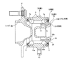
自動車の車輪は、車輪支持用ハブユニットにより懸架装置に支持する。図8〜9は、この様な車輪支持用ハブユニットの従来構造の第1例として、従動輪(FF車の後輪、FR車及びRR車の前輪)用のものを示している。この車輪支持用ハブユニット1は、軸部材であるハブ2と、内輪3と、外輪4と、複数個の転動体5、5とを備える。   The wheels of the automobile are supported on the suspension device by a wheel supporting hub unit. 8 to 9 show a first example of such a conventional wheel support hub unit for a driven wheel (rear wheel of FF vehicle, front wheel of FR vehicle and RR vehicle). The wheel support hub unit 1 includes a hub 2 that is a shaft member, an inner ring 3, an outer ring 4, and a plurality of rolling elements 5 and 5.

このうちのハブ2の外周面の外端(軸方向に関して「外」とは、自動車への組み付け状態で車両の幅方向外側を言い、図1、8、10〜14の左側。反対に軸方向に関して「内」とは、車両の幅方向中央側を言い、図1、8、10〜14の右側。本明細書全体で同じ。)寄り部分には、車輪を支持する為のフランジ6を、同じく中間部には第一の内輪軌道7aを、同じく内端部にはこの第一の内輪軌道7aを形成した部分よりも外径寸法が小さくなった小径段部8を、それぞれ形成している。尚、上記第一の内輪軌道7aは、図示の様にハブ2の中間部外周面に直接形成する場合の他、ハブの中間部に外嵌した別体の内輪の外周面に形成する場合もある。この場合には、このハブの外周面の内端部で上記別体の内輪よりも突出した部分が小径段部となり、この別体の内輪の内端面が、次述する段差面となる。   Of these, the outer end of the outer peripheral surface of the hub 2 ("outside" with respect to the axial direction refers to the outside in the width direction of the vehicle in the assembled state in the automobile, and is the left side of Figs. 1, 8, 10-14. “Inside” means the center side in the width direction of the vehicle, and the right side of FIGS. 1, 8 and 10 to 14. The same applies to the whole of this specification. Similarly, a first inner ring raceway 7a is formed in the intermediate portion, and a small diameter step portion 8 having an outer diameter smaller than that of the portion where the first inner ring raceway 7a is formed is formed in the inner end portion. . The first inner ring raceway 7a may be formed directly on the outer peripheral surface of the intermediate portion of the hub 2 as shown in the figure, or may be formed on the outer peripheral surface of a separate inner ring that is externally fitted to the intermediate portion of the hub. is there. In this case, a portion of the inner end portion of the outer peripheral surface of the hub that protrudes from the separate inner ring is a small-diameter stepped portion, and the inner end surface of the separate inner ring is a step surface described below.

又、上記内輪3は、上記小径段部8に外嵌している。この様な内輪3は、上記ハブ2の内端部に設けた円筒部10のうち、この内輪3の内端面から軸方向に突出した部分を径方向外方に塑性変形させて形成したかしめ部11により、上記小径段部8の基端部に存在する段差面9に抑え付けている。この様な内輪3の外周面には、第二の内輪軌道7bを形成している。   The inner ring 3 is externally fitted to the small diameter step 8. Such an inner ring 3 is a caulking portion formed by plastically deforming a portion protruding in the axial direction from the inner end surface of the inner ring 3 out of the cylindrical portion 10 provided at the inner end of the hub 2. 11, the stepped surface 9 is suppressed to the base end portion of the small-diameter stepped portion 8. A second inner ring raceway 7b is formed on the outer peripheral surface of such an inner ring 3.

又、上記外輪4は、外周面に外向フランジ状の取付部12を、内周面に第一、第二の外輪軌道13a、13bを、それぞれ形成している。そして、これら第一、第二の各外輪軌道13a、13bと、上記第一、第二の各内輪軌道7a、7bとの間に、それぞれ複数個ずつの転動体5、5を設けている。尚、図示の例では、これら各転動体5、5として玉を使用しているが、重量の嵩む自動車用の車輪支持用ハブユニットの場合には、これら転動体としてテーパころを使用する場合もある。又、上記各転動体5、5には、上述したかしめ部11による抑え付け力により、予圧を付与している。   The outer ring 4 has an outward flange-shaped mounting portion 12 on the outer peripheral surface and first and second outer ring raceways 13a and 13b on the inner peripheral surface. A plurality of rolling elements 5, 5 are provided between the first and second outer ring raceways 13a, 13b and the first and second inner ring raceways 7a, 7b. In the illustrated example, balls are used as the rolling elements 5 and 5. However, in the case of a heavy wheel supporting hub unit for automobiles, tapered rollers may be used as the rolling elements. is there. Further, a preload is applied to each of the rolling elements 5 and 5 by the pressing force by the caulking portion 11 described above.

次に、図10は、従動輪用の車輪支持用ハブユニットの第2例を示している。この第2例の車輪支持用ハブユニット1aは、外輪4aの外端寄り部外周面に車輪を支持固定する為のフランジ6を設けると共に、この外輪4aの径方向内側に設けた軸部材14の内端部に、懸架装置を構成するナックルに結合固定する為の取付部12を設けている。又、第二の内輪軌道7bを上記軸部材14の中間部外周面に直接形成すると共に、第一の内輪軌道7aを、この軸部材14の外端部に設けた小径段部8に外嵌した内輪3の外周面に形成している。又、この内輪3は、上記軸部材14の外端部に設けた円筒部10のうち、この小径段部8に外嵌した内輪3よりも軸方向外方に突出した部分を径方向外方に塑性変形させて形成したかしめ部11により、上記小径段部8の段差面9に向け抑え付けている。そして、このかしめ部11による抑え付け力により、複数個の転動体5、5に予圧を付与している。   Next, FIG. 10 shows a second example of a wheel support hub unit for a driven wheel. The wheel support hub unit 1a of the second example is provided with a flange 6 for supporting and fixing the wheel on the outer peripheral surface near the outer end of the outer ring 4a, and the shaft member 14 provided on the radially inner side of the outer ring 4a. A mounting portion 12 is provided at the inner end for coupling and fixing to a knuckle constituting the suspension device. Further, the second inner ring raceway 7b is formed directly on the outer peripheral surface of the intermediate portion of the shaft member 14, and the first inner ring raceway 7a is externally fitted to the small diameter step portion 8 provided at the outer end portion of the shaft member 14. The inner ring 3 is formed on the outer peripheral surface. The inner ring 3 has a cylindrical portion 10 provided at the outer end portion of the shaft member 14, and a portion projecting outward in the axial direction from the inner ring 3 fitted on the small diameter step portion 8 is radially outward. It is suppressed toward the step surface 9 of the small-diameter step portion 8 by a caulking portion 11 formed by plastic deformation. A preload is applied to the plurality of rolling elements 5 and 5 by the pressing force of the caulking portion 11.

次に、図11は、駆動輪(FF車の前輪、FR車及びRR車の後輪、4WD車の全車輪)用の車輪支持用ハブユニットの1例を示している。この駆動輪用の車輪支持用ハブユニット1bの場合、軸部材であるハブ2aの中心部に、駆動軸であるスプライン軸を係合させる為の、スプライン孔15を設けている。その他の部分の構造及び作用は、前述の図8に示した車輪支持用ハブユニット1の場合とほぼ同様である。   Next, FIG. 11 shows an example of a wheel support hub unit for driving wheels (front wheels of FF vehicles, rear wheels of FR vehicles and RR vehicles, all wheels of 4WD vehicles). In the case of this wheel supporting hub unit 1b for driving wheels, a spline hole 15 for engaging a spline shaft as a driving shaft is provided at the center of the hub 2a as a shaft member. The structure and operation of the other parts are substantially the same as in the case of the wheel supporting hub unit 1 shown in FIG.

上述した様な各車輪支持用ハブユニット1、1a、1bは何れも、内輪3を段差面9に向け、かしめ部11により抑え付ける構造を採用している。この様な構造の場合、このかしめ部11の径方向の高さを大きくした方が、このかしめ部11から上記内輪3に加えるべき力を軽減できる。即ち、図12〜13に詳示する様に、上記内輪3の内端面の径方向内端部には、この内端面の径方向中間部乃至外端部に存在する円輪状平面と上記内輪3の内周面である円筒面とを互いに滑らかに連続させる、凸曲面状の面取り部16が存在する。この為、図12に示す様に、上記内輪3の内周面を基準とする、上記かしめ部11の径方向の高さhが小さく、このかしめ部11が上記面取り部16の内径側部分のみを抑え付けている場合には、このかしめ部11から上記内輪3に加わる力Fの径方向分力Fr が大きくなり、軸方向分力Fa が小さくなる。従って、上記かしめ部11から上記内輪3に、前記各転動体5、5に適切な予圧を付与する為に必要な軸方向分力Fa を加える為には、上記力Fを相当に大きくする必要がある。ところが、この様に力Fを相当に大きくすると、上記内輪3に加わる径方向分力Fr も相当に大きくなる。この結果、この内輪3の変形量が大きくなって、内輪軌道7bの形状が崩れたり、或は予圧量が過大となる事により、寿命低下を招く可能性がある。又、上記かしめ部11の高さhが小さい為、荷重負荷時に予圧抜けが発生し、やはり寿命低下を招く可能性がある。 Each of the wheel supporting hub units 1, 1 a, 1 b as described above employs a structure in which the inner ring 3 faces the stepped surface 9 and is held down by the caulking portion 11. In the case of such a structure, the force to be applied from the caulking portion 11 to the inner ring 3 can be reduced by increasing the radial height of the caulking portion 11. That is, as shown in detail in FIGS. 12 to 13, the radially inner end portion of the inner end surface of the inner ring 3 includes an annular flat surface existing in the radially intermediate portion or outer end portion of the inner end surface and the inner ring 3. There is a chamfered portion 16 having a convex curved surface that smoothly and continuously connects the cylindrical surface that is the inner peripheral surface of each other. Therefore, as shown in FIG. 12, the radial height h of the caulking portion 11 with respect to the inner peripheral surface of the inner ring 3 is small, and the caulking portion 11 is only the inner diameter side portion of the chamfered portion 16. Is suppressed, the radial component force F r of the force F applied to the inner ring 3 from the caulking portion 11 is increased, and the axial component force F a is decreased. Thus, the inner ring 3 from the crimped portion 11, the to apply an axial force component F a need to impart the proper preload to the rolling elements 5 is increased considerably the force F There is a need. However, when the force F is considerably increased in this way, the radial component force F r applied to the inner ring 3 is also considerably increased. As a result, the amount of deformation of the inner ring 3 increases, and the shape of the inner ring raceway 7b collapses, or the preload amount becomes excessive, which may lead to a decrease in life. In addition, since the height h of the caulking portion 11 is small, preload loss occurs when a load is applied, which may also lead to a decrease in life.

これに対し、図13に示す様に、上記内輪3の内周面を基準とする、かしめ部11の径方向の高さhが大きく、このかしめ部11が上記面取り部16の全体及び上記円輪状平面の一部を抑え付けている場合には、このかしめ部11から上記内輪3に加わる力Fの径方向分力Fr が十分に小さくなり、その分、軸方向分力Fa が当該力Fとほぼ同程度に大きくなる。従って、上記かしめ部11から上記内輪3に、上記予圧を付与する為に必要な軸方向分力Fa を加える場合にも、上記かしめ部11から上記内輪3に加えるべき力Fを軽減できる。又、この様に力Fを軽減できる事と、上述の様に力Fの径方向分力Fr が十分に小さくなる事とにより、上記かしめ部11から上記内輪3に加わる径方向分力Fr を十分に小さくできる。従って、この内輪3の変形を抑える事ができる。又、上記かしめ部11の高さhが大きい為、荷重負荷時に予圧抜けを発生しにくくできる。この結果、寿命が低下する事を有効に防止できる。ところが、図13に示した構造の場合には、上記かしめ部11の径方向の高さhを大きくする為に、軸部材17の端部を径方向外方に向けて塑性変形させる量を多くする必要がある。この為、上記かしめ部11を形成するのに非常に大きな力が必要となる。従って、このかしめ部11の成形を行なうのが難しくなり、特に、このかしめ部11を狙い通りの形状に成形するのが困難となる。 On the other hand, as shown in FIG. 13, the radial height h of the caulking portion 11 with respect to the inner peripheral surface of the inner ring 3 is large, and this caulking portion 11 is the whole of the chamfered portion 16 and the circle. When a part of the annular plane is suppressed, the radial component force F r of the force F applied from the caulking portion 11 to the inner ring 3 is sufficiently small, and the axial component force F a is correspondingly reduced. It becomes almost the same as the force F. Thus, the inner ring 3 from the crimped portion 11, when applying an axial force component F a need to impart the preload can also reduce the force F to be applied to the inner ring 3 from the crimped portion 11. In addition, since the force F can be reduced in this way and the radial component force F r of the force F becomes sufficiently small as described above, the radial component force F applied to the inner ring 3 from the caulking portion 11. r can be made sufficiently small. Therefore, deformation of the inner ring 3 can be suppressed. Further, since the height h of the caulking portion 11 is large, it is difficult to cause preload loss when a load is applied. As a result, it is possible to effectively prevent the life from decreasing. However, in the case of the structure shown in FIG. 13, in order to increase the radial height h of the caulking portion 11, the amount of plastic deformation of the end portion of the shaft member 17 toward the radially outer side is increased. There is a need to. For this reason, a very large force is required to form the caulking portion 11. Therefore, it becomes difficult to mold the caulking portion 11, and in particular, it is difficult to mold the caulking portion 11 into a desired shape.

そこで、上述の様な不都合を解消できる様にすべく、特許文献1には、図14〜15に示す様な車輪支持用ハブユニットが記載されている。この車輪支持用ハブユニットの場合、図14(A)→(B)に示す様に、軸部材17aの端部(図14の右端部)のうち内輪3の端面(図14の右端面)から軸方向に突出した部分の径方向外端部を、全周に亙ってポンチ等により軸方向に加圧する事により、この径方向外端部を径方向外方に塑性変形させ、かしめ部11aを形成している。そして、このかしめ部11aにより上記内輪3の端面を抑え付けている。特に、この特許文献1に記載された車輪支持用ハブユニットの場合には、上記かしめ部11aに、径方向の高さが比較的小さい第一領域18、18と、径方向の高さが比較的大きい第二領域19、19とを、円周方向に関して交互に設けている。即ち、この様なかしめ部11aを形成する為に、上記かしめ部11aを形成する際の上記径方向外端部の軸方向への加圧量(押し込み量)を、上記各第二領域19、19に対応する部分で、上記各第一領域18、18に対応する部分よりも多くしている。これにより、上記径方向外端部に存在する肉の径方向外方への流動量が、上記各第二領域19、19に対応する部分で、上記各第一領域18、18に対応する部分よりも多くなる様にして、上記各第二領域19、19の径方向の高さを、上記各第一領域18、18の径方向の高さよりも大きくしている。   Therefore, in order to solve the above inconveniences, Patent Document 1 describes a wheel support hub unit as shown in FIGS. In the case of this wheel support hub unit, as shown in FIGS. 14A to 14B, from the end surface of the inner ring 3 (the right end surface in FIG. 14) of the end portion (the right end portion in FIG. 14) of the shaft member 17a. By pressing the radially outer end portion of the portion protruding in the axial direction in the axial direction with a punch or the like over the entire circumference, the radially outer end portion is plastically deformed radially outward, and the caulking portion 11a. Is forming. And the end surface of the said inner ring | wheel 3 is suppressed by this caulking part 11a. In particular, in the case of the wheel supporting hub unit described in Patent Document 1, the caulking portion 11a is compared with the first regions 18 and 18 having a relatively small radial height and the radial height. The large second regions 19 and 19 are alternately provided in the circumferential direction. That is, in order to form such a caulking portion 11a, the amount of pressurization (pushing amount) in the axial direction of the radially outer end when the caulking portion 11a is formed is set to each of the second regions 19, The number corresponding to 19 is greater than the number corresponding to each of the first regions 18, 18. As a result, the amount of flow of the meat present in the radially outer end portion in the radially outward direction is a portion corresponding to each of the second regions 19, 19 and a portion corresponding to each of the first regions 18, 18. The height in the radial direction of each of the second regions 19, 19 is set to be larger than the height in the radial direction of each of the first regions 18, 18.

上述の様に、特許文献1に記載された車輪支持用ハブユニットの場合には、上記かしめ部11aに、径方向の高さが比較的小さい第一領域18、18だけでなく、径方向の高さが比較的大きい第二領域19、19を設けている。この為、かしめ部の径方向の高さを全周に亙って小さくしている構造に比べて、上記かしめ部11aから上記内輪3に加えるべき力を軽減できる。これと共に、このかしめ部11aからこの内輪3に加わる径方向外方に向く力を軽減できる。この為、この内輪3に作用する円周方向の引っ張り応力を小さくする事ができる。又、径方向の高さが比較的大きい、上記各第二領域19、19は、上記かしめ部11aのうち、円周方向に関して互いに離隔した複数個所にのみ設けられており、このかしめ部11aの全周に亙って設けられてはいない。この為、かしめ部の径方向の高さを全周に亙って大きくしている構造に比べて、上記かしめ部11aを形成する際の塑性変形量を少なくできる。従って、このかしめ部11aを形成する為の力を軽減する事ができると共に、このかしめ部11aに加わる円周方向の引っ張り応力を小さくする事ができる。   As described above, in the case of the wheel support hub unit described in Patent Document 1, not only the first regions 18 and 18 having a relatively small radial height but also the radial direction in the caulking portion 11a. Second regions 19 and 19 having a relatively high height are provided. For this reason, the force to be applied from the caulking portion 11a to the inner ring 3 can be reduced as compared with the structure in which the radial height of the caulking portion is reduced over the entire circumference. At the same time, it is possible to reduce the radially outward force applied to the inner ring 3 from the caulking portion 11a. For this reason, the tensile stress in the circumferential direction acting on the inner ring 3 can be reduced. In addition, the second regions 19 and 19 having a relatively large radial height are provided only at a plurality of locations in the caulking portion 11a that are spaced apart from each other in the circumferential direction. It is not provided all around. For this reason, the amount of plastic deformation at the time of forming the caulking portion 11a can be reduced as compared with a structure in which the radial height of the caulking portion is increased over the entire circumference. Accordingly, the force for forming the caulking portion 11a can be reduced, and the tensile stress in the circumferential direction applied to the caulking portion 11a can be reduced.

上述した様な作用効果を十分に得られる様にする為には、上記各第二領域19、19の径方向の高さを、上記各第一領域18、18の径方向の高さに比べて、十分に大きくできる様にする事が望まれる。ところが、上述した様な、特許文献1に記載された車輪支持用ハブユニットの場合には、この様な要望に応える事が難しい。即ち、この特許文献1に記載された車輪支持用ハブユニットの場合には、上記各第二領域19、19の、軸方向に関する肉厚を犠牲にして、これら各第二領域19、19の径方向の高さを大きくしている。一方、これら各第二領域19、19部分の耐久性を十分に確保すべく、これら各第二領域19、19の軸方向の肉厚を所定量確保する必要がある。この為、これら各第二領域19、19の径方向の高さを十分に大きくする事はできない。従って、上述した要望に応える事が難しい。   In order to sufficiently obtain the effects as described above, the radial heights of the second regions 19 and 19 are compared with the radial heights of the first regions 18 and 18, respectively. Therefore, it is desirable to make it large enough. However, in the case of the wheel support hub unit described in Patent Document 1 as described above, it is difficult to meet such a demand. That is, in the case of the wheel supporting hub unit described in Patent Document 1, the diameters of the second regions 19 and 19 are sacrificed at the sacrifice of the thickness of the second regions 19 and 19 in the axial direction. The height of the direction is increased. On the other hand, it is necessary to secure a predetermined amount of the thickness in the axial direction of each of the second regions 19 and 19 in order to sufficiently ensure the durability of each of the second regions 19 and 19. For this reason, the radial height of each of the second regions 19, 19 cannot be made sufficiently large. Therefore, it is difficult to meet the above-mentioned demand.

特開2000−168307号公報JP 2000-168307 A

本発明の車輪支持用ハブユニットとその製造方法は、上述の様な事情に鑑み、かしめ部の径方向の高さを円周方向複数個所で他の個所に比べて十分に大きくする事ができ、しかもこれら径方向の高さを大きくした部分の耐久性を十分に確保できる様にすべく発明したものである。   In view of the circumstances as described above, the wheel support hub unit and the manufacturing method thereof according to the present invention can make the height of the caulking portion in the radial direction sufficiently larger than that at other locations at a plurality of locations in the circumferential direction. In addition, the present invention has been invented so as to ensure sufficient durability of the portion where the height in the radial direction is increased.

本発明の車輪支持用ハブユニットとその製造方法のうち、請求項1及び3に記載した車輪支持用ハブユニットは何れも、軸部材の一端部に設けた小径段部に内輪を外嵌すると共に、この内輪の一端面を、この軸部材の一端部のうちこの内輪の一端面から突出した部分を径方向外方に塑性変形させて形成したかしめ部により抑え付ける事で、上記内輪を上記軸部材に結合固定している。   Of the wheel support hub unit and the manufacturing method thereof according to the present invention, the wheel support hub unit described in claims 1 and 3 both externally fits the inner ring to a small-diameter step provided at one end of the shaft member. The inner ring is restrained by a caulking portion formed by plastically deforming one end surface of the inner ring out of one end surface of the inner ring from the one end surface of the inner ring in a radially outward direction. It is fixedly connected to the member.

特に、請求項1に記載した車輪支持用ハブユニットに於いては、上記かしめ部を形成する以前の上記軸部材の一端面の形状を、軸方向に凹んだ切り欠きを円周方向複数個所に設けた形状である、円周方向に関する第一の凹凸形状とする事により、この軸部材の一端部のうち上記内輪の一端面から突出した、上記各切り欠きの深さ寸法よりも大きな軸方向寸法を有する部分を径方向外方に塑性変形させて形成したかしめ部の外周縁の形状を、径方向内方に凹んだ凹部を円周方向複数個所に設けた形状である、円周方向に関する第二の凹凸形状としている。
一方、請求項3に記載した車輪支持用ハブユニットに於いては、上記かしめ部を形成する以前の上記軸部材の一端部を円筒部(「円筒部」の語は、凡そ円筒状である事を言い、内外両周面が完全な円筒面である場合は勿論、内外両周面の一方又は双方が、円すい面等、円筒面と異なる形状である場合も含む。本明細書及び特許請求の範囲の全体で同じ。)とし、且つ、この円筒部の内周面を円周方向に関する凹凸面とすると共に、上記かしめ部を形成する際の上記円筒部の径方向外方への塑性変形量を、上記凹凸面の各凸部に対応する部分で各凹部に対応する部分よりも多くする事により、上記かしめ部の外周縁の形状を円周方向に関する凹凸形状としている。
In particular, in the wheel supporting hub unit according to claim 1, the shape of the one end surface of the shaft member before the caulking portion is formed , and notches recessed in the axial direction are formed at a plurality of positions in the circumferential direction. An axial direction larger than the depth dimension of each notch protruding from one end surface of the inner ring out of one end of the shaft member by adopting the first uneven shape in the circumferential direction , which is the provided shape The shape of the outer peripheral edge of the caulking portion formed by plastically deforming a portion having a dimension radially outward is a shape in which concave portions recessed radially inward are provided at a plurality of locations in the circumferential direction. The second uneven shape is used.
On the other hand, in the wheel support hub unit described in claim 3 , one end portion of the shaft member before the formation of the caulking portion is a cylindrical portion (the term “cylindrical portion” is approximately cylindrical). In addition to the case where both the inner and outer peripheral surfaces are completely cylindrical surfaces, it includes the case where one or both of the inner and outer peripheral surfaces have a shape different from the cylindrical surface such as a conical surface. And the inner peripheral surface of the cylindrical portion is an uneven surface in the circumferential direction, and the amount of plastic deformation radially outward of the cylindrical portion when the caulking portion is formed. Is increased in the portion corresponding to each convex portion of the uneven surface than the portion corresponding to each concave portion, so that the shape of the outer peripheral edge of the caulking portion is an uneven shape in the circumferential direction.

又、請求項2に記載した車輪支持用ハブユニットの製造方法は、上述の請求項1に記載した車輪支持用ハブユニットを製造する方法であって、上記かしめ部を形成する以前の上記軸部材の一端面の形状を、軸方向に凹んだ切り欠きを円周方向複数個所に設けた形状である、円周方向に関する第一の凹凸形状とし、この軸部材の一端部のうち内輪の一端面から突出した、上記各切り欠きの深さ寸法よりも大きな軸方向寸法を有する部分を径方向外方に塑性変形させる事で上記かしめ部を形成する事により、このかしめ部の外周縁の形状を、径方向内方に凹んだ凹部を円周方向複数個所に設けた形状である、円周方向に関する第二の凹凸形状とする。 A method for manufacturing the wheel support hub unit according to claim 2 is a method for manufacturing the wheel support hub unit according to claim 1 described above, wherein the shaft member is formed before the caulking portion is formed. The shape of the one end surface of the inner ring is the first uneven shape in the circumferential direction , which is a shape in which notches recessed in the axial direction are provided at a plurality of locations in the circumferential direction, and one end surface of the inner ring among the one end portions of the shaft member The shape of the outer peripheral edge of the caulking portion is formed by forming the caulking portion by plastically deforming a portion having an axial dimension larger than the depth dimension of each notch protruding radially outward. The second concave-convex shape in the circumferential direction is a shape in which concave portions recessed radially inward are provided at a plurality of locations in the circumferential direction.

更に、請求項4に記載した車輪支持用ハブユニットの製造方法は、上述の請求項3に記載した車輪支持用ハブユニットを製造する方法であって、上記かしめ部を形成する以前の上記軸部材の一端部を円筒部とし、且つ、この円筒部の内周面を円周方向に関する凹凸面とすると共に、上記かしめ部を形成する際の上記円筒部の径方向外方への塑性変形量を、上記凹凸面の各凸部に対応する部分で各凹部に対応する部分よりも多くする事により、上記かしめ部の外周縁の形状を円周方向に関する凹凸形状とする。   Furthermore, the manufacturing method of the hub unit for wheel support described in claim 4 is a method of manufacturing the hub unit for wheel support described in claim 3, and the shaft member before the caulking portion is formed. One end portion of the cylindrical portion is a cylindrical portion, and the inner peripheral surface of the cylindrical portion is an uneven surface in the circumferential direction, and the amount of plastic deformation radially outward of the cylindrical portion when the caulking portion is formed is The shape of the outer peripheral edge of the caulking portion is made uneven in the circumferential direction by increasing the portion corresponding to each convex portion of the concave and convex surface than the portion corresponding to each concave portion.

上述の様に、本発明の車輪支持用ハブユニットの場合、完成後のかしめ部の外周縁の形状を円周方向に関する凹凸形状(請求項1、2に記載した発明の場合には、第二の凹凸形状)としている。この為、このかしめ部には、このかしめ部の外周縁の凹部に対応する、径方向の高さが小さい部分と、同じく凸部に対応する、径方向の高さが大きい部分とが、円周方向に関して交互に存在する。従って、本発明のかしめ部の場合には、径方向の高さが全周に亙って小さいかしめ部に比べて、円周方向複数個所に上記径方向の高さが大きい部分が存在する分だけ、当該かしめ部から内輪に加えるべき力を軽減できる。言い換えれば、この様にかしめ部から内輪に加えるべき力を軽減しても、このかしめ部からこの内輪に加えるべき軸方向の力を確保できる。特に、本発明のうち、請求項1に記載した(請求項2に記載した製造方法により造られた)車輪支持用ハブユニットの場合には、軸部材の一端面のうち、(第一の凹凸形状の)各凸部に対応する部分の軸方向長さを大きくする事により、請求項3に記載した(請求項4に記載した製造方法により造られた)車輪支持用ハブユニットの場合には、円筒部の内周面のうち、各凸部に対応する部分の径方向高さを大きくする事により、完成後のかしめ部のうち、このかしめ部の外周縁の各凸部に対応する部分の径方向高さを、同じく各凹部に対応する部分の径方向高さよりも十分に大きくする事ができる。この為、上記かしめ部から上記内輪に加えるべき力を十分に軽減する事ができる。これと共に、上記かしめ部から上記内輪に加わる径方向外方に向く力を十分に小さくできる。この為、この内輪に加わる円周方向の引っ張り応力を十分に小さくする事ができ、この内輪に過度な変形等が生じる事を有効に防止できる。 As described above, in the case of the hub unit for supporting a wheel according to the present invention, the shape of the outer peripheral edge of the caulked portion after completion is the uneven shape in the circumferential direction (in the case of the invention described in claims 1 and 2, the second Concavo-convex shape) . For this reason, the caulking portion includes a portion having a small radial height corresponding to the concave portion of the outer peripheral edge of the caulking portion and a portion having a large radial height corresponding to the convex portion. It exists alternately in the circumferential direction. Therefore, in the case of the caulking portion of the present invention, compared to the caulking portion where the radial height is small over the entire circumference, there are portions where the radial height is large at a plurality of locations in the circumferential direction. Only the force to be applied to the inner ring from the caulking portion can be reduced. In other words, even if the force to be applied from the caulking portion to the inner ring is reduced in this way, the axial force to be applied from the caulking portion to the inner ring can be ensured. In particular, of the present invention, set forth in claim 1 in the case of (the built by the manufacturing method according to claim 2) for supporting a wheel hub unit, of the end face of the shaft member, (the first irregularity In the case of the wheel supporting hub unit described in claim 3 (made by the manufacturing method described in claim 4), by increasing the axial length of the part corresponding to each convex part (of the shape) Of the inner circumferential surface of the cylindrical portion, by increasing the radial height of the portion corresponding to each convex portion, the portion corresponding to each convex portion on the outer peripheral edge of this crimped portion of the crimped portion after completion The height in the radial direction can be made sufficiently larger than the radial height of the portion corresponding to each recess. For this reason, the force to be applied to the inner ring from the caulking portion can be sufficiently reduced. At the same time, it is possible to sufficiently reduce the radially outward force applied from the caulking portion to the inner ring. For this reason, the tensile stress in the circumferential direction applied to the inner ring can be sufficiently reduced, and excessive deformation and the like can be effectively prevented from occurring in the inner ring.

又、本発明の場合、上記かしめ部には、円周方向に関して互いに隣り合う、径方向の高さが大きい部分同士の間に、それぞれ径方向の高さが小さい部分が存在する。この為、本発明のかしめ部の場合、径方向高さが全周に亙って大きいかしめ部に比べて、当該かしめ部を形成する為に必要となる力を十分に小さくする事ができる。これと共に、このかしめ部に加わる円周方向の引っ張り応力を十分に小さくできる。この為、このかしめ部の成形性が向上し、このかしめ部を狙い通りの形状に成形するのが容易となる。   In the case of the present invention, the caulking portion has a portion having a small radial height between portions having a large radial height that are adjacent to each other in the circumferential direction. For this reason, in the case of the caulking portion of the present invention, the force required to form the caulking portion can be sufficiently reduced as compared with the caulking portion whose radial height is large over the entire circumference. At the same time, the tensile stress in the circumferential direction applied to the caulking portion can be sufficiently reduced. For this reason, the moldability of this caulking part is improved, and it becomes easy to form this caulking part into a desired shape.

又、本発明の場合には、上記かしめ部のうち、このかしめ部の外周縁の各凸部に対応する、径方向の高さが大きい部分の肉厚を十分に確保できる。
即ち、請求項1に記載した(請求項2に記載した製造方法により造られた)車輪支持用ハブユニットの場合には、軸部材の一端部を径方向外方に塑性変形させる事に伴い、この軸部材の一端部のうち、この軸部材の一端面の各凸部に対応する部分が、それぞれ上記かしめ部のうち径方向の高さが大きい部分となる。この様に、請求項1に記載した(請求項2に記載した製造方法により造られた)車輪支持用ハブユニットの場合には、上記かしめ部のうち径方向の高さが大きい部分を形成する為に、当該部分の軸方向に関する肉厚を小さくすると言った手段を採用していない。この為、上記かしめ部のうち径方向の高さが大きい部分の、軸方向に関する肉厚を十分に確保できる。
又、請求項3に記載した(請求項4に記載した製造方法により造られた)車輪支持用ハブユニットの場合には、円筒部の径方向外方への塑性変形量を、凹凸面の各凸部に対応する部分で各凹部に対応する部分よりも多くする事に伴い、これら各凸部に対応する部分が、それぞれ上記かしめ部のうち径方向の高さが大きい部分となる。この様な請求項3に記載した(請求項4に記載した製造方法により造られた)車輪支持用ハブユニットの場合、塑性変形に伴う上記円筒部の肉厚の減少量は、上記各凸部に対応する部分で上記各凹部に対応する部分よりも多くなる。但し、塑性変形前の上記円筒部の肉厚は、上記各凸部に対応する部分で上記各凹部に対応する部分よりも大きくなっている。従って、上述の様に塑性変形に伴う円筒部の肉厚の減少量が上記各凸部に対応する部分で上記各凹部に対応する部分よりも多くなっても、塑性変形前のこれら各凸部に対応する部分の肉厚を調節すると共に、これら各凸部に対応する部分の肉厚の減少量を規制する事により、上記かしめ部のうち径方向の高さが大きい部分の肉厚を十分に確保できる。
この様に本発明の場合には、上記かしめ部のうち径方向の高さが大きい部分の肉厚を十分に確保できる為、このかしめ部の耐久性を十分に確保できる。
Moreover, in the case of this invention, the thickness of the part with a large radial direction corresponding to each convex part of the outer periphery of this caulking part is fully securable among the said caulking parts.
That is, in the case of the wheel supporting hub unit described in claim 1 (made by the manufacturing method described in claim 2), along with plastically deforming one end portion of the shaft member radially outward, Of the one end portion of the shaft member, a portion corresponding to each convex portion on one end surface of the shaft member is a portion having a large radial height in the caulking portion. Thus, in the case of the wheel supporting hub unit described in claim 1 (made by the manufacturing method described in claim 2), a portion having a large radial height is formed in the caulking portion. Therefore, the means of reducing the thickness of the portion in the axial direction is not adopted. For this reason, it is possible to sufficiently secure the thickness in the axial direction of the caulking portion where the radial height is large.
Further, in the case of the wheel supporting hub unit described in claim 3 (made by the manufacturing method described in claim 4), the amount of plastic deformation in the radially outward direction of the cylindrical portion is determined for each uneven surface. As the portions corresponding to the convex portions are made larger than the portions corresponding to the respective concave portions, the portions corresponding to the respective convex portions become the portions having a large radial height in the caulking portion. In the case of such a wheel-supporting hub unit described in claim 3 (made by the manufacturing method described in claim 4), the amount of reduction in the thickness of the cylindrical portion due to plastic deformation is such that each convex portion is In the portion corresponding to the above, more than the portion corresponding to each of the recesses. However, the thickness of the cylindrical portion before plastic deformation is larger at the portions corresponding to the convex portions than at the portions corresponding to the concave portions. Therefore, as described above, even if the amount of reduction in the thickness of the cylindrical portion due to plastic deformation is greater in the portion corresponding to each of the convex portions than in the portion corresponding to the respective concave portions, these convex portions before the plastic deformation. By adjusting the wall thickness of the part corresponding to the above and the amount of reduction in the wall thickness of the part corresponding to each of these convex parts, the thickness of the caulking part with a large radial height is sufficient. Can be secured.
Thus, in the case of this invention, since the thickness of a part with a large radial direction among the said crimping parts can be ensured enough, the durability of this crimping part can fully be ensured.

図1〜3は、請求項1〜2に対応する、本発明の実施例1を示している。尚、本実施例の特徴は、軸部材であるハブ2bの内端部に設けるかしめ部11bの構造にある。その他の部分の構造及び作用は、前述の図8〜9に示した従来構造の第1例の場合と同様であるから、同等部分には同一符号を付して重複する説明を省略若しくは簡略にし、以下、本実施例の特徴部分を中心に説明する。   1 to 3 show Embodiment 1 of the present invention corresponding to claims 1 and 2. The feature of this embodiment is the structure of the caulking portion 11b provided at the inner end portion of the hub 2b which is a shaft member. The structure and operation of the other parts are the same as in the case of the first example of the conventional structure shown in FIGS. 8 to 9 described above. Hereinafter, the characteristic part of the present embodiment will be mainly described.

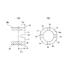
図3に示す様に、上記かしめ部11bを形成する以前の上記ハブ2bの内端部には、円筒部10aを設けている。これと共に、この円筒部10aの円周方向複数個所(図示の例では、円周方向等間隔の4個所)に、それぞれこの円筒部10aの内端縁に開口する(軸方向外方に凹んだ)切り欠き20、20を形成している。これにより、これら各切り欠20、20同士の間に舌片21、21を設けて、上記円筒部10aの内端縁の形状を、円周方向に関する第一の凹凸形状としている。又、本実施例の場合には、上記各切り欠き20、20(上記各舌片21、21)の軸方向長さ{図3(A)の左右方向長さ}L20を、上記円筒部10aの内端部のうち、内輪3の内端面から軸方向内方に突出して、上記かしめ部11bを形成する際に径方向外方に塑性変形させる部分(かしめ代22)の軸方向長さL22よりも小さく(L20<L22)している。 As shown in FIG. 3, a cylindrical portion 10a is provided at the inner end of the hub 2b before the caulking portion 11b is formed. At the same time, the cylindrical portion 10a has openings at a plurality of locations in the circumferential direction (in the illustrated example, four locations at equal intervals in the circumferential direction), each opening at the inner end edge of the cylindrical portion 10a (dented outward in the axial direction). ) Notches 20 and 20 are formed. Thereby, the tongue pieces 21 and 21 are provided between these notches 20 and 20, and the shape of the inner edge of the said cylindrical part 10a is made into the 1st uneven | corrugated shape regarding the circumferential direction. In the case of the present embodiment, the axial length {the lateral length in FIG. 3A} L 20 of the notches 20 and 20 (the tongue pieces 21 and 21) is set to the cylindrical portion. Of the inner end portion of 10a, the axial length of the portion that protrudes inward in the axial direction from the inner end surface of the inner ring 3 and is plastically deformed radially outward when the caulking portion 11b is formed. is smaller (L 20 <L 22) than L 22.

そして、上記かしめ代22を全周に亙って径方向外方に塑性変形させる事により、図1〜2に示す様な、外周縁の形状が、径方向内方に凹んだ凹部23、23を円周方向複数個所に設けた形状で、円周方向に関する第二の凹凸形状であるかしめ部11bを形成している。そして、このかしめ部11bにより内輪3を、上記ハブ2bの内端寄り部に設けた段差面9に向け抑え付けている。 Then, by plastically deforming radially outward across the caulking margin 22 all around, such as shown in FIGS. 1-2, the shape of the outer periphery, recesses radially recessed inwardly 23 Are formed at a plurality of locations in the circumferential direction, and the caulking portion 11b is formed as a second uneven shape in the circumferential direction. The caulking portion 11b holds the inner ring 3 toward the step surface 9 provided near the inner end of the hub 2b.

上述の様に、本実施例の車輪支持用ハブユニットの場合、完成後のかしめ部11bの外周縁の形状を円周方向に関する第二の凹凸形状としている。この為、このかしめ部11bには、このかしめ部11bの外周縁の上記各凹部23、23に対応する、径方向の高さが小さい部分と、同じく凸部24、24に対応する、径方向の高さが大きい部分とが、円周方向に関して交互に存在する。従って、本実施例のかしめ部11bの場合には、径方向の高さが全周に亙って小さいかしめ部に比べて、円周方向複数個所に上記各凸部24、24に対応する部分が存在する分だけ、当該かしめ部11bから上記内輪3に加えるべき力を軽減できる。言い換えれば、この様にかしめ部11bから内輪3に加えるべき力を軽減しても、このかしめ部11bからこの内輪3に加えるべき軸方向の力を確保できる。 As described above, in the case of the wheel supporting hub unit of the present embodiment, the shape of the outer peripheral edge of the crimped portion 11b after completion is the second uneven shape in the circumferential direction. Therefore, the caulking portion 11b, corresponding to the respective recesses 23, 23 of the outer peripheral edge of the caulking portion 11b, a height small portion of the radial, also corresponding to the convex portions 24 and 24, radially The portions having a large height are alternately present in the circumferential direction. Therefore, in the case of the caulking portion 11b according to the present embodiment, compared with the caulking portion whose height in the radial direction is small over the entire circumference, portions corresponding to the convex portions 24 and 24 at a plurality of positions in the circumferential direction. Therefore, the force to be applied to the inner ring 3 from the caulking portion 11b can be reduced by the amount that exists. In other words, even if the force to be applied to the inner ring 3 from the caulking portion 11b is reduced in this way, the axial force to be applied to the inner ring 3 from the caulking portion 11b can be secured.

特に、本実施例の場合には、上記円筒部10aの内端部のうち、上記各舌片21、21の軸方向長さを大きくする事により、完成後のかしめ部11aのうち、上記各凸部24、24に対応する部分の径方向高さを、上記各凹部23、23に対応する部分の径方向高さよりも十分に大きくする事ができる。この為、各転動体5、5に付与する予圧を確保すべく、上記かしめ部11bから上記内輪3に加えるべき力を十分に低減する事ができる。これと共に、上記かしめ部11bから上記内輪3に加わる、径方向外方に向く力Fr を十分に小さくできる。この為、この内輪3に加わる円周方向の引っ張り応力を十分に小さくする事ができ、この内輪3に過度な変形等が生じる事を有効に防止できる。 In particular, in the case of the present embodiment, by increasing the axial length of each of the tongue pieces 21 and 21 in the inner end portion of the cylindrical portion 10a, each of the above-described caulking portions 11a among the above-described caulking portions 11a. The radial height of the portion corresponding to the convex portions 24, 24 can be made sufficiently larger than the radial height of the portion corresponding to the concave portions 23, 23. For this reason, it is possible to sufficiently reduce the force to be applied to the inner ring 3 from the caulking portion 11b in order to ensure the preload applied to the rolling elements 5 and 5. At the same time, it is possible to sufficiently reduce the radially outward force F r applied to the inner ring 3 from the caulking portion 11b. For this reason, the tensile stress in the circumferential direction applied to the inner ring 3 can be made sufficiently small, and it is possible to effectively prevent the inner ring 3 from being excessively deformed.

又、本実施例の場合、上記かしめ部11bには、上記各凸部24、24に対応する、径方向の高さが大きい部分同士の間に、上記各凹部23、23に対応する、径方向の高さが小さい部分が存在する。この為、本実施例のかしめ部11bの場合、径方向高さが全周に亙って大きいかしめ部に比べて、当該かしめ部11bを形成する為に必要となる力を十分に小さくする事ができる。これと共に、このかしめ部11bに加わる円周方向の引っ張り応力を十分に小さくできる。この為、このかしめ部11bの成形性が向上し、このかしめ部11を狙い通りの形状に成形するのが容易となる。又、このかしめ部11に過度な変形等が生じる事を有効に防止できる。   In the case of the present embodiment, the caulking portion 11b has a diameter corresponding to each of the concave portions 23 and 23 between the portions having a large radial height corresponding to the convex portions 24 and 24. There is a portion with a small height in the direction. For this reason, in the case of the caulking portion 11b of the present embodiment, the force required to form the caulking portion 11b is made sufficiently smaller than that of the caulking portion whose radial height is large over the entire circumference. Can do. At the same time, the tensile stress in the circumferential direction applied to the caulking portion 11b can be sufficiently reduced. For this reason, the moldability of the caulking portion 11b is improved, and it becomes easy to form the caulking portion 11 into a desired shape. Further, it is possible to effectively prevent the caulking portion 11 from being excessively deformed.

又、本実施例の場合、上記かしめ部11bのうち、上記各凸部24、24に対応する、径方向の高さが大きい部分の、軸方向に関する肉厚を十分に確保できる。即ち、本実施例の場合には、上記円筒部10aの内端部を径方向外方に塑性変形させる事に伴い、この円筒部10aの内端部のうち、上記各舌片21、21に対応する部分が、それぞれ上記かしめ部11bのうち径方向の高さが大きい部分となる。この様に、本実施例の場合には、上記かしめ部11bのうち径方向の高さが大きい部分を形成する為に、当該部分の軸方向に関する肉厚を小さくすると言った手段を採用していない。この為、上記かしめ部11bのうち径方向の高さが大きい部分の、軸方向に関する肉厚を十分に確保できる。
この様に本実施例の場合には、上記かしめ部11bのうち径方向の高さが大きい部分の、軸方向に関する肉厚を十分に確保できる為、このかしめ部11bの強度、剛性、耐久性を、何れも十分に確保できる。
In the case of the present embodiment, it is possible to sufficiently secure the thickness in the axial direction of the caulking portion 11b corresponding to the convex portions 24 and 24 and having a large radial height. That is, in the case of the present embodiment, as the inner end portion of the cylindrical portion 10a is plastically deformed radially outward, among the inner end portions of the cylindrical portion 10a, Corresponding portions are portions of the caulking portion 11b having a large radial height. Thus, in the case of the present embodiment, in order to form a portion having a large radial height in the caulking portion 11b, means for reducing the thickness of the portion in the axial direction is adopted. Absent. For this reason, the thickness in the axial direction of the portion having a large radial height in the caulking portion 11b can be sufficiently secured.
Thus, in the case of the present embodiment, since the thickness in the axial direction of the portion having a large radial direction in the caulking portion 11b can be sufficiently secured, the strength, rigidity, and durability of the caulking portion 11b are ensured. Can be sufficiently secured.

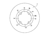
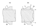
次に、図4〜5は、請求項3〜4に対応する、本発明の実施例2を示している。本実施例の場合、図4に示す様に、かしめ部11c(図5)を形成する以前のハブ2cの内端部に、円筒部10bを設けている。又、この円筒部10bの外周面を単なる円筒面とすると共に、この円筒部10bの内周面を円周方向に関する凹凸面としている。これにより、この円筒部10bのうち、この凹凸面の各凸部25、25に対応する部分を、各凹部26、26に対応する部分よりも径方向の肉厚が大きい部分としている。尚、請求項3〜4に記載した発明を実施する場合、上記凹凸面を構成する各凸部25、25及び各凹部26、26の個数や円周方向に関する配置の位相は任意であるが、図示の例では、それぞれ4個ずつ、円周方向に関して交互に且つ等間隔で設けている。   Next, FIGS. 4-5 has shown Example 2 of this invention corresponding to Claims 3-4. In the case of the present embodiment, as shown in FIG. 4, a cylindrical portion 10b is provided at the inner end of the hub 2c before the caulking portion 11c (FIG. 5) is formed. The outer peripheral surface of the cylindrical portion 10b is a simple cylindrical surface, and the inner peripheral surface of the cylindrical portion 10b is an uneven surface in the circumferential direction. Thereby, the part corresponding to each convex part 25 of this cylindrical surface 10b of this cylindrical part 10b is made into the part whose radial thickness is larger than the part corresponding to each recessed part 26,26. In the case of carrying out the invention described in claims 3 to 4, the number of the convex portions 25, 25 and the concave portions 26, 26 constituting the concave and convex surface and the phase of arrangement in the circumferential direction are arbitrary. In the illustrated example, four each are provided alternately at equal intervals in the circumferential direction.

上記かしめ部11cを形成する際には、上記円筒部10bの内端部を径方向外方に塑性変形させるが、本実施例の場合には、この際の円筒部10bの径方向外方への塑性変形量(及び軸方向に関する圧縮量)を、この円筒部10bの内周面のうち、上記各凸部25、25に対応する部分で上記各凹部26、26に対応する部分よりも多くする。これにより、図5に示す様に、上記かしめ部11cの外周縁の形状を、円周方向に関する凹凸形状とする。即ち、この様にして形成した本実施例のかしめ部11cの場合も、このかしめ部11cの外周縁の凸部24a、24aに対応する、径方向の高さが大きい部分と、同じく凹部23a、23aに対応する、径方向の高さが小さい部分とが、円周方向に関して交互に存在する。   When the caulking portion 11c is formed, the inner end portion of the cylindrical portion 10b is plastically deformed radially outward. In this embodiment, the cylindrical portion 10b is moved radially outward. The amount of plastic deformation (and the amount of compression in the axial direction) of the inner peripheral surface of the cylindrical portion 10b is larger at the portion corresponding to the convex portions 25 and 25 than at the portion corresponding to the concave portions 26 and 26. To do. Thereby, as shown in FIG. 5, the shape of the outer periphery of the said caulking part 11c is made into the uneven | corrugated shape regarding the circumferential direction. That is, in the case of the caulking portion 11c of the present embodiment formed in this way, a portion having a large radial height corresponding to the convex portions 24a and 24a on the outer peripheral edge of the caulking portion 11c, and the concave portion 23a, The portions corresponding to 23a and having a small radial height alternately exist in the circumferential direction.

上述の様に、本実施例の場合も、完成後のかしめ部11cの外周縁の形状を円周方向に関する凹凸形状にしている。又、本実施例の場合には、上記円筒部10bの内周面のうち、上記各凸部25、25に対応する部分の径方向高さを大きくする事により、完成後のかしめ部11cのうち、このかしめ部11cの外周縁の各凸部24a、24aに対応する部分の径方向高さを、同じく各凹部23a、23aに対応する部分の径方向高さよりも十分に大きくしている。更に、本実施例の場合も、上記かしめ部11cのうち、このかしめ部11cの外周縁の各凸部24a、24aに対応する、径方向の高さが大きい部分の、軸方向に関する肉厚を十分に確保できる。即ち、本実施例の場合、上記かしめ部11cを形成する際の塑性変形に伴う、上記円筒部10bの、軸方向に関する肉厚の減少量は、この円筒部10bの内周面の各凸部25、25(上記各凸部24a、24a)に対応する部分で、同じく各凹部26、26(上記各凹部23a、23a)に対応する部分よりも多くなる。但し、塑性変形前の上記円筒部10bの、径方向に関する肉厚は、上記各凸部25、25に対応する部分で上記各凹部26、26に対応する部分よりも大きくなっている。従って、塑性変形前の上記各凸部25、25に対応する部分の、径方向に関する肉厚や、これら各凸部25、25に対応する部分の肉厚の減少量を規制する事により、上記かしめ部11cのうち径方向の高さが大きい部分の、軸方向に関する肉厚を十分に確保できる。
従って、本実施例の場合も、上記かしめ部に関して、上述した実施例1の場合と同様の作用効果を奏する事ができる。
As described above, also in the case of the present embodiment, the shape of the outer peripheral edge of the caulking portion 11c after completion is an uneven shape in the circumferential direction. Further, in the case of the present embodiment, by increasing the radial height of the portion corresponding to each of the convex portions 25, 25 in the inner peripheral surface of the cylindrical portion 10b, the crimped portion 11c after completion is completed. Among these, the radial height of the portion corresponding to the convex portions 24a, 24a on the outer peripheral edge of the caulking portion 11c is made sufficiently larger than the radial height of the portion corresponding to the concave portions 23a, 23a. Furthermore, also in the present embodiment, the thickness in the axial direction of the caulking portion 11c corresponding to the convex portions 24a and 24a on the outer peripheral edge of the caulking portion 11c is large. Enough can be secured. That is, in the case of the present embodiment, the thickness reduction amount in the axial direction of the cylindrical portion 10b due to the plastic deformation at the time of forming the caulking portion 11c is the convex portion of the inner peripheral surface of the cylindrical portion 10b. 25 and 25 (the respective convex portions 24a and 24a) are larger than the portions corresponding to the respective concave portions 26 and 26 (the respective concave portions 23a and 23a). However, the thickness in the radial direction of the cylindrical portion 10b before plastic deformation is larger at the portions corresponding to the convex portions 25 and 25 than at the portions corresponding to the concave portions 26 and 26. Therefore, by regulating the thickness in the radial direction of the portions corresponding to the respective convex portions 25, 25 before plastic deformation and the amount of decrease in the thickness of the portions corresponding to the respective convex portions 25, 25, A sufficient thickness in the axial direction can be secured at a portion of the caulking portion 11c having a large radial height.
Therefore, also in the case of the present embodiment, the same effects as those of the above-described first embodiment can be achieved with respect to the caulking portion.

次に、図6〜7は、やはり請求項3、4に対応する、本発明の実施例3を示している。本実施例の場合には、かしめ部11d(図7)を形成する以前の円筒部10cの内周面である、円周方向に関する凹凸面を構成する凸部25、25及び凹部26、26の個数を、それぞれ上述した実施例2の場合よりも多くしている(図示の例では、それぞれ7個ずつとしている)。その他の部分の構造及び作用は、上述した実施例2の場合と同様である為、同等部分には同一符号を付して重複する説明は省略する。   Next, FIGS. 6 to 7 show a third embodiment of the present invention, which also corresponds to claims 3 and 4. In the case of the present embodiment, the convex portions 25 and 25 and the concave portions 26 and 26 constituting the concave-convex surface in the circumferential direction, which is the inner peripheral surface of the cylindrical portion 10c before the caulking portion 11d (FIG. 7) is formed. The number is larger than that in the above-described second embodiment (seven in the illustrated example). Since the structure and operation of the other parts are the same as in the case of the above-described second embodiment, the same parts are denoted by the same reference numerals, and redundant description is omitted.

尚、上述した各実施例を実施する場合、かしめ部を形成する以前の円筒部10a〜10cは、従来構造の円筒部(外周面が単なる円筒面であると共に、内周面が単なる円筒面若しくは円すい面であり、且つ、内端面が全周に亙り単一の仮想平面上に存在する円筒部)の場合と同様、鍛造加工や切削加工等により形成する事ができる。この場合、加工コストを抑える観点から、上記各円筒部10a〜10cと上記従来構造の円筒部とで、それぞれ加工工数が等しくなる様にする事が好ましい。この様な目的を達成する為に、例えば、上記各円筒部10a〜10cの内端面又は内周面に対し、これら各面の形状に合わせた押型を用いて鍛造加工を施したり、或は、波形に動く事ができる工具を用いて旋削加工を施す事ができる。   In addition, when implementing each Example mentioned above, cylindrical part 10a-10c before forming a caulking part is a cylindrical part of a conventional structure (The outer peripheral surface is a mere cylindrical surface, and an inner peripheral surface is a mere cylindrical surface or It can be formed by forging, cutting, or the like, as in the case of a conical surface and an inner end surface extending over the entire circumference on a single virtual plane). In this case, from the viewpoint of reducing the processing cost, it is preferable that the processing man-hours are equal in each of the cylindrical portions 10a to 10c and the cylindrical portion having the conventional structure. In order to achieve such an object, for example, the inner end surface or the inner peripheral surface of each of the cylindrical portions 10a to 10c is subjected to forging using a die that matches the shape of each surface, or It can be turned with a tool that can move in a wave shape.

本発明の実施例1を示す断面図。Sectional drawing which shows Example 1 of this invention. 要部のみを取り出して示す、図1の右側から見た図。The figure seen from the right side of FIG. 1 which takes out and shows only the principal part. かしめ部を形成する以前の円筒部の、(A)は断面図、(B)は(A)の右側から見た図。The cylindrical part before forming a crimp part, (A) is sectional drawing, (B) is the figure seen from the right side of (A). 本発明の実施例2を示す、かしめ部を形成する以前の要部の状態を軸方向から見た図。The figure which looked at the state of the principal part before forming the crimping part from the axial direction which shows Example 2 of this invention. 同じく、かしめ部を形成した後の要部の状態を軸方向から見た図。Similarly, the figure which looked at the state of the principal part after forming a caulking part from the axial direction. 本発明の実施例3を示す、図4と同様の図。The figure similar to FIG. 4 which shows Example 3 of this invention. 同じく、図5と同様の図。Similarly, the same figure as FIG. 従来構造の第1例を示す断面図。Sectional drawing which shows the 1st example of a conventional structure. 要部のみを取り出して示す、図8の右側から見た図。The figure seen from the right side of FIG. 従来構造の第2例を示す断面図。Sectional drawing which shows the 2nd example of a conventional structure. 同第3例を示す断面図。Sectional drawing which shows the 3rd example. 径方向の高さhが小さいかしめ部から内輪に加わる力Fを説明する為の要部断面図。The principal part sectional drawing for demonstrating the force F added to an inner ring | wheel from the crimping part where the height h of radial direction is small. 径方向の高さhが大きいかしめ部から内輪に加わる力Fを説明する為の要部断面図。The principal part sectional drawing for demonstrating the force F added to an inner ring | wheel from the crimping part where the height h of radial direction is large. 従来構造の第4例の、かしめ部を形成する工程を示す要部断面図。The principal part sectional drawing which shows the process of forming the crimping part of the 4th example of conventional structure. 図14(B)の右側から見た図。The figure seen from the right side of FIG.

符号の説明Explanation of symbols

1、1a、1b 車輪支持用ハブユニット
2、2a、2b、2c ハブ
3 内輪
、4a 外輪
5 転動体
6 フランジ
7a、7b 内輪軌道
8 小径段部
9 段差面
10、10a〜10c 円筒部
11、11a〜11d かしめ部
12 取付部
13a、13b 外輪軌道
14 軸部材
15 スプライン孔
16 面取り部
17、17a 軸部材
18 第一領域
19 第二領域
20 切り欠き
21 舌片
22 かしめ代
23、23a 凹部
24、24a 凸部
25 凸部
26 凹部
DESCRIPTION OF SYMBOLS 1, 1a, 1b Wheel support hub unit 2, 2a, 2b, 2c Hub 3 Inner ring 4 , 4a Outer ring 5 Rolling element 6 Flange 7a, 7b Inner ring track 8 Small diameter step part 9 Step surface 10, 10a-10c Cylindrical part 11, 11a to 11d Caulking portion 12 Mounting portion 13a, 13b Outer ring raceway 14 Shaft member 15 Spline hole 16 Chamfered portion 17, 17a Shaft member 18 First region 19 Second region 20 Notch 21 Tongue piece 22 Caulking allowance 23, 23a Recessed portion 24, 24a convex part 25 convex part 26 concave part

Claims (4)

軸部材の一端部に設けた小径段部に内輪を外嵌すると共に、この内輪の一端面を、この軸部材の一端部のうちこの内輪の一端面から突出した部分を径方向外方に塑性変形させて形成したかしめ部により抑え付ける事で、上記内輪を上記軸部材に結合固定している車輪支持用ハブユニットに於いて、上記かしめ部を形成する以前の上記軸部材の一端面の形状を、軸方向に凹んだ切り欠きを円周方向複数個所に設けた形状である、円周方向に関する第一の凹凸形状とする事により、この軸部材の一端部のうち上記内輪の一端面から突出した、上記各切り欠きの深さ寸法よりも大きな軸方向寸法を有する部分を径方向外方に塑性変形させて形成したかしめ部の外周縁の形状を、径方向内方に凹んだ凹部を円周方向複数個所に設けた形状である、円周方向に関する第二の凹凸形状とした事を特徴とする車輪支持用ハブユニット。 The inner ring is externally fitted to a small-diameter step provided at one end of the shaft member, and one end surface of the inner ring is plasticized radially outward from the end of the end of the shaft member. In the wheel support hub unit in which the inner ring is coupled and fixed to the shaft member by being restrained by a deformed caulking portion, the shape of one end surface of the shaft member before the caulking portion is formed From the one end surface of the inner ring among the one end portions of the shaft member, by making the first concave-convex shape in the circumferential direction , which is a shape provided with a plurality of notches recessed in the axial direction in the circumferential direction . A protruding concave portion formed by plastically deforming a portion having an axial dimension larger than the depth dimension of each notch in the radially outward direction, and having a concave portion recessed inward in the radial direction. a shape provided in the circumferential direction a plurality of locations, the circumferential Wheel supporting hub unit, characterized in that the the second uneven shape related direction. 請求項1に記載した車輪支持用ハブユニットの製造方法であって、かしめ部を形成する以前の軸部材の一端面の形状を、軸方向に凹んだ切り欠きを円周方向複数個所に設けた形状である、円周方向に関する第一の凹凸形状とし、この軸部材の一端部のうち内輪の一端面から突出した、上記各切り欠きの深さ寸法よりも大きな軸方向寸法を有する部分を径方向外方に塑性変形させる事で上記かしめ部を形成する事により、このかしめ部の外周縁の形状を、径方向内方に凹んだ凹部を円周方向複数個所に設けた形状である、円周方向に関する第二の凹凸形状とする、車輪支持用ハブユニットの製造方法。 The wheel support hub unit manufacturing method according to claim 1, wherein the shape of one end surface of the shaft member before forming the caulking portion is provided with notches recessed in the axial direction at a plurality of locations in the circumferential direction. The shape is a first concavo-convex shape in the circumferential direction , and a portion having an axial dimension larger than the depth dimension of each of the notches protruding from one end face of the inner ring of one end portion of the shaft member is a diameter. By forming the caulking portion by plastic deformation outward in the direction, the shape of the outer peripheral edge of the caulking portion is a shape in which concave portions recessed radially inward are provided at a plurality of locations in the circumferential direction, A method for manufacturing a wheel-supporting hub unit having a second uneven shape in the circumferential direction. 軸部材の一端部に設けた小径段部に内輪を外嵌すると共に、この内輪の一端面を、この軸部材の一端部のうちこの内輪の一端面から突出した部分を径方向外方に塑性変形させて形成したかしめ部により抑え付ける事で、上記内輪を上記軸部材に結合固定している車輪支持用ハブユニットに於いて、上記かしめ部を形成する以前の上記軸部材の一端部を円筒部とし、且つ、この円筒部の内周面を円周方向に関する凹凸面とすると共に、上記かしめ部を形成する際の上記円筒部の径方向外方への塑性変形量を、上記凹凸面の各凸部に対応する部分で各凹部に対応する部分よりも多くする事により、上記かしめ部の外周縁の形状を円周方向に関する凹凸形状とした事を特徴とする車輪支持用ハブユニット。   The inner ring is externally fitted to a small-diameter step provided at one end of the shaft member, and one end surface of the inner ring is plasticized radially outward from the end of the end of the shaft member. In the hub unit for supporting the wheel, in which the inner ring is coupled and fixed to the shaft member by restraining it with a deformed caulking portion, one end portion of the shaft member before forming the caulking portion is cylindrical. And the inner circumferential surface of the cylindrical portion is an uneven surface in the circumferential direction, and the amount of plastic deformation radially outward of the cylindrical portion when forming the caulking portion is A wheel support hub unit characterized in that the shape of the outer peripheral edge of the caulking portion is an uneven shape in the circumferential direction by increasing the portion corresponding to each convex portion more than the portion corresponding to each concave portion. 請求項3に記載した車輪支持用ハブユニットの製造方法であって、かしめ部を形成する以前の軸部材の一端部を円筒部とし、且つ、この円筒部の内周面を円周方向に関する凹凸面とすると共に、上記かしめ部を形成する際の上記円筒部の径方向外方への塑性変形量を、上記凹凸面の各凸部に対応する部分で各凹部に対応する部分よりも多くする事により、上記かしめ部の外周縁の形状を円周方向に関する凹凸形状とする、車輪支持用ハブユニットの製造方法。   The wheel support hub unit manufacturing method according to claim 3, wherein one end portion of the shaft member before forming the caulking portion is a cylindrical portion, and the inner peripheral surface of the cylindrical portion is uneven in the circumferential direction. And the amount of plastic deformation in the radially outward direction of the cylindrical portion when forming the caulking portion is larger than the portion corresponding to each concave portion at the portion corresponding to each convex portion of the concave and convex surface. The manufacturing method of the hub unit for wheel support which makes the shape of the outer periphery of the said crimping part the uneven | corrugated shape regarding the circumferential direction by the thing.
JP2004020108A 2004-01-28 2004-01-28 Wheel support hub unit and manufacturing method thereof Expired - Fee Related JP4281563B2 (en)

Priority Applications (1)

Application Number Priority Date Filing Date Title
JP2004020108A JP4281563B2 (en) 2004-01-28 2004-01-28 Wheel support hub unit and manufacturing method thereof

Applications Claiming Priority (1)

Application Number Priority Date Filing Date Title
JP2004020108A JP4281563B2 (en) 2004-01-28 2004-01-28 Wheel support hub unit and manufacturing method thereof

Publications (3)

Publication Number Publication Date
JP2005212561A JP2005212561A (en) 2005-08-11
JP2005212561A5 JP2005212561A5 (en) 2006-10-12
JP4281563B2 true JP4281563B2 (en) 2009-06-17

Family

ID=34904126

Family Applications (1)

Application Number Title Priority Date Filing Date
JP2004020108A Expired - Fee Related JP4281563B2 (en) 2004-01-28 2004-01-28 Wheel support hub unit and manufacturing method thereof

Country Status (1)

Country Link
JP (1) JP4281563B2 (en)

Families Citing this family (1)

* Cited by examiner, † Cited by third party
Publication number Priority date Publication date Assignee Title
JP2007069838A (en) * 2005-09-09 2007-03-22 Jtekt Corp Rolling bearing device

Also Published As

Publication number Publication date
JP2005212561A (en) 2005-08-11

Similar Documents

Publication Publication Date Title
EP1566286B1 (en) Race member in hub unit and method of producing the same
JP3855315B2 (en) Manufacturing method of wheel bearing rolling bearing unit
JP4936712B2 (en) Wheel bearing device
JP2003074571A (en) Srolling bearing unit for driving wheel and driving unit for car wheel
JP4299957B2 (en) Manufacturing method of bearing device
JP4604634B2 (en) Rolling bearing device and manufacturing method thereof
EP3546777B1 (en) Hub unit bearing, method for manufacturing same, motor vehicle, and method for manufacturing same
JP5228343B2 (en) Double row rolling bearing unit for wheel support and manufacturing method thereof
JP2002225503A (en) Method of producing hub unit for supporting wheel and pressing die for producing the same
JP4281563B2 (en) Wheel support hub unit and manufacturing method thereof
JP4078945B2 (en) Rolling bearing device
JP4239249B2 (en) Manufacturing method of bearing device
JP4239542B2 (en) Rolling bearing device
JP5182144B2 (en) Method for manufacturing bearing ring member
JP4538844B2 (en) Wheel bearing device
EP1889734B1 (en) Axle bearing apparatus and method of producing hub shaft for driving wheel bearing apparatus
JP2007192342A (en) Bearing unit for vehicle
JP4059268B2 (en) Rolling bearing unit for wheel support and manufacturing method thereof
JP2005090613A (en) Wheel supporting hub unit
JP4178669B2 (en) Manufacturing method of bearing device
JP2006144990A (en) Rolling bearing device
JP2003056580A (en) Bearing device for axle
JP5150990B2 (en) Manufacturing method of axle bearing device
JP4193353B2 (en) Axle bearing device and manufacturing method thereof
JP5592661B2 (en) Manufacturing method of bearing device

Legal Events

Date Code Title Description
A521 Written amendment

Free format text: JAPANESE INTERMEDIATE CODE: A523

Effective date: 20060824

A621 Written request for application examination

Free format text: JAPANESE INTERMEDIATE CODE: A621

Effective date: 20060824

RD04 Notification of resignation of power of attorney

Free format text: JAPANESE INTERMEDIATE CODE: A7424

Effective date: 20060824

A977 Report on retrieval

Free format text: JAPANESE INTERMEDIATE CODE: A971007

Effective date: 20080709

A131 Notification of reasons for refusal

Free format text: JAPANESE INTERMEDIATE CODE: A131

Effective date: 20080722

A521 Written amendment

Free format text: JAPANESE INTERMEDIATE CODE: A523

Effective date: 20080912

TRDD Decision of grant or rejection written
A01 Written decision to grant a patent or to grant a registration (utility model)

Free format text: JAPANESE INTERMEDIATE CODE: A01

Effective date: 20090224

A01 Written decision to grant a patent or to grant a registration (utility model)

Free format text: JAPANESE INTERMEDIATE CODE: A01

A61 First payment of annual fees (during grant procedure)

Free format text: JAPANESE INTERMEDIATE CODE: A61

Effective date: 20090309

R150 Certificate of patent or registration of utility model

Free format text: JAPANESE INTERMEDIATE CODE: R150

FPAY Renewal fee payment (event date is renewal date of database)

Free format text: PAYMENT UNTIL: 20120327

Year of fee payment: 3

LAPS Cancellation because of no payment of annual fees