JP4279719B2 - Failure diagnosis device for fuel vapor purge system, and fuel vapor purge device and combustion engine provided with the same - Google Patents
Failure diagnosis device for fuel vapor purge system, and fuel vapor purge device and combustion engine provided with the same Download PDFInfo
- Publication number
- JP4279719B2 JP4279719B2 JP2004119062A JP2004119062A JP4279719B2 JP 4279719 B2 JP4279719 B2 JP 4279719B2 JP 2004119062 A JP2004119062 A JP 2004119062A JP 2004119062 A JP2004119062 A JP 2004119062A JP 4279719 B2 JP4279719 B2 JP 4279719B2
- Authority
- JP
- Japan
- Prior art keywords
- fuel vapor
- failure diagnosis
- amount
- canister
- purge
- Prior art date
- Legal status (The legal status is an assumption and is not a legal conclusion. Google has not performed a legal analysis and makes no representation as to the accuracy of the status listed.)
- Expired - Fee Related
Links
Images


Classifications
-
- F—MECHANICAL ENGINEERING; LIGHTING; HEATING; WEAPONS; BLASTING
- F02—COMBUSTION ENGINES; HOT-GAS OR COMBUSTION-PRODUCT ENGINE PLANTS
- F02M—SUPPLYING COMBUSTION ENGINES IN GENERAL WITH COMBUSTIBLE MIXTURES OR CONSTITUENTS THEREOF
- F02M25/00—Engine-pertinent apparatus for adding non-fuel substances or small quantities of secondary fuel to combustion-air, main fuel or fuel-air mixture
- F02M25/08—Engine-pertinent apparatus for adding non-fuel substances or small quantities of secondary fuel to combustion-air, main fuel or fuel-air mixture adding fuel vapours drawn from engine fuel reservoir
- F02M25/0809—Judging failure of purge control system
- F02M25/0818—Judging failure of purge control system having means for pressurising the evaporative emission space
-
- F—MECHANICAL ENGINEERING; LIGHTING; HEATING; WEAPONS; BLASTING
- F02—COMBUSTION ENGINES; HOT-GAS OR COMBUSTION-PRODUCT ENGINE PLANTS
- F02M—SUPPLYING COMBUSTION ENGINES IN GENERAL WITH COMBUSTIBLE MIXTURES OR CONSTITUENTS THEREOF
- F02M25/00—Engine-pertinent apparatus for adding non-fuel substances or small quantities of secondary fuel to combustion-air, main fuel or fuel-air mixture
- F02M25/08—Engine-pertinent apparatus for adding non-fuel substances or small quantities of secondary fuel to combustion-air, main fuel or fuel-air mixture adding fuel vapours drawn from engine fuel reservoir
- F02M25/089—Layout of the fuel vapour installation
Description
この発明は、燃料タンクで発生した燃料蒸気を吸気系へパージする燃料蒸気パージシステムの故障診断装置、ならびにそれを備えた燃料蒸気パージ装置および燃焼機関に関する。 The present invention relates to a failure diagnosis device for a fuel vapor purge system that purges fuel vapor generated in a fuel tank into an intake system, and a fuel vapor purge device and a combustion engine equipped with the failure diagnosis device.
揮発性液体燃料の燃料タンクを備えた車両においては、燃料タンクで発生した燃料蒸気を吸気系へパージする燃料蒸気パージシステムが一般的に備えられている。このような燃料蒸気パージシステムにおいては、燃料タンクで発生した燃料蒸気は、ベーパ通路を介して燃料タンクと接続されるキャニスタで一旦吸着されて捕集され、その後、パージ通路を介してキャニスタと接続されるエンジンの吸気通路にパージされる。 2. Description of the Related Art A vehicle equipped with a volatile liquid fuel fuel tank is generally equipped with a fuel vapor purge system that purges fuel vapor generated in the fuel tank into an intake system. In such a fuel vapor purge system, the fuel vapor generated in the fuel tank is once adsorbed and collected by a canister connected to the fuel tank via the vapor passage, and then connected to the canister via the purge passage. Purged into the intake passage of the engine.
このような燃料蒸気パージシステムの多くにおいては、システムの信頼性を確保するために、燃料タンク、ベーパ通路、キャニスタおよびパージ通路を含む経路(以下、この経路を「エバポ経路」とも称する。)の孔あきや裂傷などに起因する燃料蒸気の漏れを発見するための故障診断装置が設けられている。このような故障診断装置においては、電動ポンプを用いてエバポ経路内に外部と差圧を発生させてエバポ経路内の圧力を測定し、その測定された圧力を所定の基準圧と比較することによって、エバポ経路における漏れの有無が診断される。 In many of such fuel vapor purge systems, in order to ensure the reliability of the system, a route including a fuel tank, a vapor passage, a canister, and a purge passage (hereinafter, this route is also referred to as an “evaporation route”). A failure diagnosis device is provided to detect fuel vapor leaks due to perforations or lacerations. In such a fault diagnosis device, an electric pump is used to generate a differential pressure with the outside in the evaporation path, measure the pressure in the evaporation path, and compare the measured pressure with a predetermined reference pressure. The presence or absence of leakage in the evaporation path is diagnosed.
特開2003−269265号公報は、このような燃料蒸気パージシステムの故障診断装置を開示する。この故障診断装置においては、燃料蒸気の発生によるエバポ経路内圧への影響を考慮して、異常判定すべき孔の径からなる基準孔に対して加圧されたときの基準圧を事前に検出された燃料蒸気発生時の圧力を用いて補正し、その補正された基準圧を用いてエバポ経路における漏れの有無が判定される(特許文献1参照)。 Japanese Patent Laying-Open No. 2003-269265 discloses a failure diagnosis apparatus for such a fuel vapor purge system. In this failure diagnosis device, in consideration of the influence on the evaporation path internal pressure due to the generation of fuel vapor, the reference pressure when the pressure is applied to the reference hole made up of the diameter of the hole to be determined as abnormal is detected in advance. Correction is made using the pressure at the time of fuel vapor generation, and the presence or absence of leakage in the evaporation path is determined using the corrected reference pressure (see Patent Document 1).
この特開2003−269265号公報に開示された故障診断装置によれば、エバポ経路の漏れ故障の判定精度を向上させることができる。
しかしながら、特開2003−269265号公報に開示された故障診断装置では、キャニスタ内が燃料蒸気で満たされているときに故障診断が行なわれると、エバポ経路内に圧力を与えた際に、キャニスタ内に吸着されている燃料蒸気が外部へ放出され、あるいは、燃料タンク内に存在する燃料蒸気がキャニスタで吸着されずに外部へ放出されてしまう。 However, in the failure diagnosis device disclosed in Japanese Patent Application Laid-Open No. 2003-269265, if failure diagnosis is performed when the canister is filled with fuel vapor, the inside of the canister The fuel vapor adsorbed on the fuel is released to the outside, or the fuel vapor existing in the fuel tank is released to the outside without being adsorbed by the canister.
そこで、この発明は、かかる課題を解決するためになされたものであり、その目的は、故障診断中に外部へ放出される燃料蒸気量を低減する燃料蒸気パージシステムの故障診断装置を提供することである。 Accordingly, the present invention has been made to solve such a problem, and an object thereof is to provide a failure diagnosis device for a fuel vapor purge system that reduces the amount of fuel vapor released to the outside during failure diagnosis. It is.
また、この発明の別の目的は、故障診断中に外部へ放出される燃料蒸気量を低減する故障診断装置を備えた燃料蒸気パージ装置を提供することである。 Another object of the present invention is to provide a fuel vapor purge apparatus including a failure diagnosis device that reduces the amount of fuel vapor released to the outside during failure diagnosis.
また、この発明の別の目的は、故障診断中に外部へ放出される燃料蒸気量を低減する故障診断装置を備えた燃焼機関を提供することである。 Another object of the present invention is to provide a combustion engine equipped with a failure diagnosis device that reduces the amount of fuel vapor released to the outside during failure diagnosis.
この発明によれば、燃料蒸気パージシステムの故障診断装置は、燃料タンクにおいて発生した燃料蒸気をキャニスタ内で吸着させ、その吸着された燃料蒸気を吸気系へパージする燃料蒸気パージシステムの故障診断装置であって、故障診断の実行時、燃料タンクおよびキャニスタを含む燃料蒸気の経路内に外部との圧力差を発生させる差圧発生手段と、差圧発生手段によって圧力差を発生させたときの経路内の圧力を所定の基準圧と比較し、その比較結果に基づいて故障の有無を診断する故障診断手段と、経路内における燃料蒸気量が所定の基準量よりも少ないか否かによって、差圧発生手段および故障診断手段による故障診断を実行するか否かを決定する実行判定手段とを備える。 According to the present invention, a failure diagnosis apparatus for a fuel vapor purge system causes a fuel vapor generated in a fuel tank to be adsorbed in a canister and purges the adsorbed fuel vapor to an intake system. And a differential pressure generating means for generating a pressure difference with the outside in the path of the fuel vapor including the fuel tank and the canister, and a path when the pressure difference is generated by the differential pressure generating means when performing the failure diagnosis The pressure difference is determined by a failure diagnosis means for diagnosing the presence or absence of a failure based on the comparison result and whether or not the amount of fuel vapor in the path is smaller than the predetermined reference amount. And an execution determination means for determining whether or not to execute failure diagnosis by the generation means and the failure diagnosis means.
好ましくは、実行判定手段は、キャニスタに吸着されている燃料蒸気量が第1の所定量よりも少ないとき、経路内における燃料蒸気量が所定の基準量よりも少ないと判断する。 Preferably, the execution determination unit determines that the amount of fuel vapor in the path is less than a predetermined reference amount when the amount of fuel vapor adsorbed on the canister is smaller than the first predetermined amount.
好ましくは、実行判定手段は、燃料蒸気のパージ量に基づいて、キャニスタに吸着されている燃料蒸気量を推定する。 Preferably, the execution determination unit estimates the amount of fuel vapor adsorbed on the canister based on the purge amount of fuel vapor.
好ましくは、パージ量は、故障診断前の燃焼機関動作時における累積パージ量である。 Preferably, the purge amount is a cumulative purge amount during operation of the combustion engine before failure diagnosis.
好ましくは、実行判定手段は、燃料蒸気のパージ量が第2の所定量よりも多いとき、キャニスタに吸着されている燃料蒸気量が第1の所定量よりも少ないと判断する。 Preferably, the execution determination unit determines that the amount of fuel vapor adsorbed on the canister is smaller than the first predetermined amount when the purge amount of the fuel vapor is larger than the second predetermined amount.
好ましくは、第2の所定量は、燃料蒸気パージシステムの温度が高いほど多い。 Preferably, the second predetermined amount is higher as the temperature of the fuel vapor purge system is higher.
好ましくは、第2の所定量は、燃料蒸気パージシステムの温度上昇が大きいほど多い。 Preferably, the second predetermined amount is larger as the temperature rise of the fuel vapor purge system is larger.
好ましくは、実行判定手段は、キャニスタを吸気系と接続するパージ通路に設けられるパージ制御弁の開弁時間に基づいてパージ量を算出する。 Preferably, the execution determination unit calculates the purge amount based on a valve opening time of a purge control valve provided in a purge passage connecting the canister to the intake system.
また、この発明によれば、燃料蒸気パージシステムの故障診断装置は、燃料タンクにおいて発生した燃料蒸気をキャニスタ内で吸着させ、その吸着された燃料蒸気を吸気系へパージする燃料蒸気パージシステムの故障診断装置であって、故障診断の実行時、燃料タンクおよびキャニスタを含む燃料蒸気の経路内に外部との圧力差を発生させる差圧発生手段と、差圧発生手段によって圧力差を発生させたときの経路内の圧力を所定の基準圧と比較し、その比較結果に基づいて故障の有無を診断する故障診断手段と、経路内の燃料蒸気濃度を検出する濃度検出手段と、濃度検出手段によって検出された燃料蒸気濃度が所定値よりも低いか否かによって、差圧発生手段および故障診断手段による故障診断を実行するか否かを決定する実行判定手段とを備える。 According to the present invention, the failure diagnosis device for the fuel vapor purge system causes the fuel vapor generated in the fuel tank to be adsorbed in the canister, and the failure of the fuel vapor purge system purges the adsorbed fuel vapor to the intake system. A diagnostic device for generating a pressure difference with the differential pressure generating means for generating a pressure difference with the outside in the fuel vapor path including the fuel tank and the canister when performing the fault diagnosis, and when the pressure differential is generated by the differential pressure generating means The pressure in the path is compared with a predetermined reference pressure, and a failure diagnosis means for diagnosing the presence or absence of a failure based on the comparison result, a concentration detection means for detecting the fuel vapor concentration in the path, and detection by the concentration detection means Execution determination means for determining whether or not to perform failure diagnosis by the differential pressure generation means and the failure diagnosis means depending on whether or not the fuel vapor concentration is lower than a predetermined value; Provided.
好ましくは、差圧発生手段は、外気に対して経路内に負圧を発生させる。 Preferably, the differential pressure generating means generates a negative pressure in the path with respect to the outside air.
また、この発明によれば、燃料蒸気パージ装置は、上述したいずれかの燃料蒸気パージシステムの故障診断装置を備える。 Further, according to the present invention, the fuel vapor purge device includes any of the above-described failure diagnosis devices for the fuel vapor purge system.
また、この発明によれば、燃焼機関は、上述したいずれかの燃料蒸気パージシステムの故障診断装置を備える。 According to the invention, the combustion engine includes any one of the above-described failure diagnosis devices for the fuel vapor purge system.
この発明による燃料蒸気パージシステムの故障診断装置においては、実行判定手段は、エバポ経路内における燃料蒸気量に基づいて故障診断を実行するか否かを決定し、エバポ経路における燃料蒸気量が多いときは、故障診断を実行しない。 In the fuel vapor purge system failure diagnosis apparatus according to the present invention, the execution determination means determines whether or not to execute failure diagnosis based on the amount of fuel vapor in the evaporation path, and when the amount of fuel vapor in the evaporation path is large. Does not perform fault diagnosis.
したがって、この発明によれば、燃料蒸気の外部への放出を防止することができる。 Therefore, according to the present invention, it is possible to prevent the fuel vapor from being released to the outside.
また、この発明による燃料蒸気パージシステムの故障診断装置においては、実行判定手段は、キャニスタに吸着されている燃料蒸気量に基づいて、経路内における燃料蒸気量が所定の基準量よりも少ないか否かを判断する。そして、実行判定手段は、燃料蒸気のパージ量に基づいて、キャニスタに吸着されている燃料蒸気量を推定する。 In the failure diagnosis apparatus for a fuel vapor purge system according to the present invention, the execution determination means determines whether the fuel vapor amount in the path is smaller than a predetermined reference amount based on the fuel vapor amount adsorbed on the canister. Determine whether. The execution determining means estimates the amount of fuel vapor adsorbed on the canister based on the purge amount of fuel vapor.
したがって、この発明によれば、直接の測定が難しいキャニスタの吸着量を検出することなく、故障診断の実行を判定できる。 Therefore, according to the present invention, it is possible to determine the execution of the failure diagnosis without detecting the adsorption amount of the canister that is difficult to directly measure.
また、この発明による燃料蒸気パージシステムの故障診断装置においては、燃料蒸気パージシステムの温度が高いほど、または温度上昇が大きいほど、事前の燃料蒸気のパージ量が必要とされる。 In the failure diagnosis apparatus for a fuel vapor purge system according to the present invention, the fuel vapor purge system needs to be purged in advance as the temperature of the fuel vapor purge system is higher or as the temperature rises.
したがって、この発明によれば、燃料蒸気パージシステムの温度を考慮した、より精度の高い故障診断実行判定を行なうことができる。 Therefore, according to the present invention, it is possible to perform failure diagnosis execution determination with higher accuracy in consideration of the temperature of the fuel vapor purge system.
また、この発明によれば、実行判定手段は、パージ制御弁の開弁時間に基づいてパージ量を算出するので、パージ量を検出する装置を別途設ける必要がない。 Further, according to the present invention, the execution determining means calculates the purge amount based on the valve opening time of the purge control valve, so that it is not necessary to separately provide a device for detecting the purge amount.
また、この発明による燃料蒸気パージシステムの故障診断装置においては、実行判定手段は、濃度検出手段によって検出された燃料蒸気濃度に基づいて故障診断を実行するか否かを決定し、エバポ経路における燃料蒸気濃度が高いときは、故障診断を実行しない。 In the failure diagnosis apparatus for a fuel vapor purge system according to the present invention, the execution determination means determines whether or not to execute failure diagnosis based on the fuel vapor concentration detected by the concentration detection means, and determines the fuel in the evaporation path. When the vapor concentration is high, failure diagnosis is not performed.
したがって、この発明によっても、燃料蒸気の外部への放出を防止することができる。 Therefore, according to the present invention, release of fuel vapor to the outside can be prevented.
以下、本発明の実施の形態について、図面を参照しながら詳細に説明する。なお、図中同一または相当部分には同一符号を付してその説明は繰返さない。 Hereinafter, embodiments of the present invention will be described in detail with reference to the drawings. In the drawings, the same or corresponding parts are denoted by the same reference numerals and description thereof will not be repeated.
[実施の形態1]
図1は、この発明による故障診断装置を備えた燃料蒸気パージシステムの概略構成図である。
[Embodiment 1]
FIG. 1 is a schematic configuration diagram of a fuel vapor purge system equipped with a failure diagnosis apparatus according to the present invention.
図1を参照して、燃料蒸気パージシステム20は、燃料タンク22と、キャニスタ24と、ベーパ通路26と、パージ通路28と、内圧弁50と、パージ制御弁64と、大気導入通路30と、防塵フィルタ68と、電動ポンプモジュール70と、ECU(Electronic Control Unit)72とを備える。燃料タンク22は、ベーパ通路26を介してキャニスタ24と接続される。キャニスタ24は、パージ通路28を介してサージタンク12と接続される。内圧弁50は、ベーパ通路26に設けられ、パージ制御弁64は、パージ通路28に設けられる。また、大気導入通路30は、電動ポンプモジュール70を介してキャニスタ24に接続され、防塵フィルタ68は、大気導入通路30に設けられる。
Referring to FIG. 1, a fuel
この燃料蒸気パージシステム20によって燃料が供給されるエンジン10は、サージタンク12と接続される。サージタンク12は、エンジン10に吸入空気を導く吸気通路16およびパージ通路28と接続され、パージ通路28から供給される燃料蒸気を吸気通路16から供給される吸入空気と混合してエンジン10に供給する。吸気通路16のサージタンク12上流側には、スロットルバルブ18が設けられ、そのさらに上流にはエアクリーナ14が設けられている。
The
燃料タンク22は、フロート弁40,46と、液溜め部42,48と、絞り44とを含む。フロート弁40、液溜め部42および絞り44は、燃料タンク22の上部壁に接続され、かつ、燃料タンク22内で分岐されたベーパ通路26の一方に接続される。フロート弁46および液溜め部48は、その分岐されたベーパ通路26の他方に接続される。
The
また、燃料タンク22は、給油管32と接続される。給油管32の給油口には、キャップ34が設けられ、給油口32の出口には、逆止弁36が設けられている。さらに、給油管32には、循環路38が分岐して設けられており、循環路38の開口端は、燃料タンク22内の上部空間に開口している。
The
ベーパ通路26は、燃料タンク22内で発生した燃料蒸気をキャニスタ24へ送るための通路である。内圧弁50は、ベーパ通路26のキャニスタ24近傍に設けられ、内部にダイアフラムおよび絞り52を有する。燃料タンク22内の内圧が内圧弁50の開弁圧よりも低いとき、ダイアフラムは閉弁位置にあり、内圧弁50は、絞り52を介して燃料タンク22をキャニスタ24と連通する。一方、燃料タンク22内の内圧が内圧弁50の開弁圧に達しているとき、ダイアフラムは開弁位置に移動し、内圧弁50は、絞り52を介さずに燃料タンク22をキャニスタ24と連通する。
The
キャニスタ24は、吸着材を含み、燃料タンク22からベーパ通路26を介して供給される燃料蒸気を吸着材に吸着させて一時的に蓄積する。そして、キャニスタ24は、パージ通路28を介して接続されるサージタンク12によって負圧が与えられると、吸着材に吸着されている燃料蒸気をパージ通路28を介してサージタンク12へ放出(パージ)する。
The
キャニスタ24は、仕切板54と、吸着材室56,58と、通気フィルタ60と、ガイド部62とを含む。吸着材室56,58は、吸着材で内部が満たされており、仕切板54によって互いに区画され、通気フィルタ60を介して互いに連通している。吸着材室56は、ベーパ通路26を介して燃料タンク22と連通しており、さらに、パージ通路28を介してサージタンク12とも連通している。吸着材室58は、大気導入通路30を介して外部と連通している。ガイド部62は、燃料タンク22からベーパ通路26を介してキャニスタ24内に流入した燃料蒸気が一旦は吸着材に吸着された後にパージ通路28へパージされるようにするために設けられている。
The
パージ制御弁64は、ECU72からの制御指令に応じて動作し、パージ制御弁64が開弁すると、エンジン10の運転中にサージタンク12内に発生する吸気負圧がパージ通路28を介してキャニスタ24内に与えられる。
The
大気導入通路30は、給油用開口部に設けられたインレット口元66から入る空気を電動ポンプモジュール70を介してキャニスタ24内に供給するための通路である。防塵フィルタ68は、インレット口元66から供給される空気に含まれる粉塵を除去する。
The
電動ポンプモジュール70は、電動式エアポンプと、切換弁と、基準孔と、圧力センサとを含む(いずれも図示せず)。電動ポンプモジュール70は、ECU72からの制御指令に応じて動作し、エンジン10の動作中は、電動式エアポンプを動作させることなく、キャニスタ24を大気導入通路30と連通させる。
The
一方、電動ポンプモジュール70は、燃料蒸気パージシステム20の故障診断時は、ECU72からの制御指令に応じて電動式エアポンプを動作させ、故障診断の判定値を得るための基準孔およびキャニスタ24内に負圧を発生させる。そして、電動ポンプモジュール70は、負圧を発生させたときの基準孔およびキャニスタ24内の圧力を圧力センサによって検出し、その検出した圧力値をECU72へ出力する。なお、この燃料蒸気パージシステム20の故障診断時の動作については、後ほど詳しく説明する。
On the other hand, the
ECU72は、CPU(Central Processing Unit)、ROM(Read Only Memory)、RAM(Random Access Memory)、A/D(Analog/Digital)変換器および入出力インターフェース等を含む。ECU72は、図示されない各種センサによって検出されるエンジン10の回転速度や、吸入空気量、排気系の空燃比、車速などの情報に基づいて、燃料噴射制御などエンジン10の運転に係る各種制御を実行する。また、ECU72は、パージ制御弁64を駆動制御し、燃料蒸気パージシステム20のパージ制御を実行する。さらに、ECU72は、電動ポンプユニット70を駆動制御し、電動ポンプユニット70の圧力センサから受ける圧力検出値に基づいて、燃料蒸気パージシステム20の故障診断を実行する。
The
この燃料蒸気パージシステム20においては、エンジン10の運転中に燃料タンク22内で発生した燃料蒸気は、ベーパ通路26を介してキャニスタ24内に流入し、キャニスタ24内の吸着材に一旦吸着される。そして、ECU72からの制御指令に応じてパージ制御弁64が開弁すると、サージタンク12からパージ通路28を介してキャニスタ24内に吸気負圧が導入される。そうすると、キャニスタ24内に吸着されていた燃料蒸気がキャニスタ24からパージ通路28を介してサージタンク12へパージされる。
In the fuel
次に、この燃料蒸気パージシステム20の故障診断について説明する。電動ポンプモジュール70およびECU72は、燃料蒸気パージシステム20の故障診断装置を構成する。燃料蒸気パージシステム20の故障診断時、まず、電動ポンプモジュール70は、ECU72からの制御指令に基づいて切換弁を移動させ、大気導入通路30、電動式エアポンプ、基準孔および大気導入通路30からなる経路を構成する。次に、電動ポンプモジュール70は、ECU72からの制御指令に基づいて電動式エアポンプを駆動し、基準孔に負圧を発生させる。そして、電動ポンプモジュール70は、電動式エアポンプと基準孔との間の圧力を圧力センサによって検出し、その検出した圧力をECU72へ出力する。
Next, failure diagnosis of the fuel
ここで、基準孔は、燃料蒸気パージシステム20におけるエバポ経路において検出すべき孔の大きさに設定されており、このときに圧力センサによって検出された第1の圧力がエバポ経路における故障診断の判定値となる。
Here, the reference hole is set to the size of the hole to be detected in the evaporation path in the fuel
基準孔を用いて故障診断の判定値が決定されると、電動ポンプモジュール70は、ECU72からの制御指令に基づいて切換弁を移動させ、キャニスタ24、電動式エアポンプおよび大気導入通路30からなる経路を構成する。そして、電動ポンプモジュール70は、ECU72からの制御指令に基づいて電動式エアポンプを駆動し、キャニスタ24内に負圧を発生させる。そして、電動ポンプモジュール70は、キャニスタ24内の第2の圧力を圧力センサによって検出し、その検出した圧力をECU72へ出力する。
When the determination value for failure diagnosis is determined using the reference hole, the
ECU72は、エンジン10および車両の停止後、所定時間(たとえば5時間)経過すると、燃料蒸気パージシステム20の故障診断に先立ち、故障診断を実行するか否かを判定する。すなわち、上述したように、燃料蒸気パージシステム20の故障診断時は、電動ポンプモジュール70によってキャニスタ24内に負圧が導入されるところ、キャニスタ24における燃料蒸気の吸着量が飽和状態に近いときは、燃料タンク22から発生した燃料蒸気をキャニスタ24が吸着できず、大量の燃料蒸気が大気に放出されてしまう。そこで、ECU72は、キャニスタ24の吸着量が所定量以上のときは、故障診断を実行しない。
The
一方、キャニスタ24の吸着能力に余裕があるときは、電動ポンプモジュール70による負圧導入時に燃料タンク22から発生する燃料蒸気をキャニスタ24が吸着するので、燃料蒸気が大気へ放出されることはない。そこで、ECU72は、キャニスタ24の吸着量が所定量よりも少ないときは、故障診断を実行する。
On the other hand, when the
ECU72は、故障診断の実行を判断すると、電動ポンプモジュール70へ電動式エアポンプおよび切換弁の動作指令を出力し、電動ポンプモジュール70の圧力センサから上述した第1および第2の圧力を受ける。そして、ECU72は、この第1および第2の圧力検出値をそれぞれ故障診断の判定圧Prefおよび測定圧Pとして故障診断処理を実行する。
When the
なお、ECU72は、燃料蒸気パージシステム20の故障診断実行中、パージ制御弁64が閉弁するようにパージ制御弁64に制御指令を出力し、これによって、エバポ経路内は、閉鎖された空間となっている。
The
なお、上記において、電動ポンプモジュール70は、「差圧発生手段」を構成する。
In the above, the
図2は、燃料蒸気パージシステム20の故障診断実行時における圧力変化を示す図である。この図2では、時刻t2以降において、エバポ経路が正常時の圧力変化が実線L1で示され、エバポ経路が異常(孔有り)時の圧力変化が点線L2で示されている。
FIG. 2 is a diagram illustrating a pressure change when the failure diagnosis of the fuel
図2を参照して、時刻t1において、故障診断の実行が開始される。電動ポンプモジュール70は、ECU72からの動作指令に応じて、基準孔を用いた判定圧Prefの測定を開始する。そして、ECU72は、電動ポンプモジュール70から受ける圧力検出値の変化が十分に小さくなったときの圧力を故障診断の判定圧Prefとする。
Referring to FIG. 2, at time t1, execution of failure diagnosis is started. The
時刻t2において、電動ポンプモジュール70は、ECU72からの動作指令に応じて、キャニスタ24への負圧の付与を開始する。そして、エバポ経路が正常のとき、すなわち、エバポ経路に基準孔よりも大きい孔がないとき、キャニスタ24内の圧力は、判定圧Prefよりも低くなり、これによって、ECU72は、エバポ経路が正常であると診断する。一方、エバポ経路に異常があるとき、すなわち、エバポ経路に基準孔よりも大きい孔があるとき、キャニスタ24内の圧力は、判定圧Prefまで下がらず、これによって、ECU72は、エバポ経路が異常であると診断する。
At time t <b> 2, the
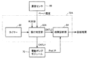
図3は、図1に示したECU72の故障診断処理に関する構成を示す機能ブロック図である。
FIG. 3 is a functional block diagram showing a configuration relating to failure diagnosis processing of the
図3を参照して、ECU72は、タイマー80と、実行判定部82と、故障診断部84とを含む。タイマー80は、エンジン10および車両の停止後、燃料蒸気パージシステム20の故障診断の実行が開始されるまでの時間を計時する。また、タイマー80のカウント値は、実行判定部82によって、パージ制御弁64の累積開弁時間の算出にも用いられる。
Referring to FIG. 3,
実行判定部82は、エンジン10の動作中、パージ通路28に設けられたパージ制御弁64の開弁指令(または開弁実績)に基づいてパージ制御弁64の累積開弁時間をカウントし、その累積開弁時間に基づいてエンジン10の動作中における累積パージ量を算出する。また、実行判定部82は、タイマー80からエンジン10および車両の停止後所定時間を経過した旨の通知を受けると、たとえばエンジン水温計を用いてそのときの温度を取得する。
The
さらに、実行判定部82は、図示されないROMから必要パージ量テーブルを読出す。ここで、必要パージ量は、故障診断実行時におけるキャニスタ24内のベーパ吸着量が相当量か否かを判定するためのものであって、実行判定部82は、算出したエンジン10の動作中における累積パージ量を必要パージ量と比較し、累積パージ量が必要パージ量G1よりも多いと判断したときは、故障診断の実行が可能であると判断する。一方、実行判定部82は、累積パージ量が必要パージ量G1以下であると判断したときは、故障診断を実行しない。
Furthermore, the
すなわち、故障診断前のエンジン10の動作時に相当量のパージがなされていれば、キャニスタ24内における燃料蒸気の吸着量は減少しており、故障診断を実行してもキャニスタ24には十分な吸着能力があるので燃料蒸気が大気に大量放出されることはないものとして、実行判定部82は、故障診断の実行開始を電動ポンプモジュール70および故障診断部84に指示する。
That is, if a considerable amount of purge is performed during operation of the
一方、故障診断前のエンジン10の動作時におけるパージ量が十分でなければ、キャニスタ24内は燃料蒸気で満たされており、故障診断を実行すると、キャニスタ24には吸着能力に余裕がないので燃料蒸気が大気に大量放出されるものとして、実行判定部82は、故障診断を実行しない。
On the other hand, if the purge amount during the operation of the
そして、実行判定部82は、故障診断の実行が可能であると判断すると、制御指令CNTL1、CNTL2をそれぞれ電動ポンプモジュール70および故障診断部84へ出力する。
When the
ここで、温度が高いほど、燃料タンク22から発生する燃料蒸気の量が多くなるのでキャニスタ24の吸着量は増加し、故障診断時におけるキャニスタ24の吸着能力に余裕がなくなる。そこで、温度が高いときほど、事前に十分にパージされている必要があるため、必要パージ量は、温度に依存した値からなる。
Here, as the temperature increases, the amount of fuel vapor generated from the
図4は、図3に示した実行判定部82によって故障診断の実行可否判定に用いられる必要パージ量の温度依存を示す図である。図4を参照して、温度が高くなるにつれて必要パージ量が多くなっており、温度が高いときほど、事前に十分なパージがなされている必要がある。なお、この図4では、必要パージ量の値の一例が示されており、故障診断の実行可否判定に用いられる必要パージ量は、これらの値に限られるものではない。
FIG. 4 is a diagram showing the temperature dependence of the required purge amount used for determining whether or not failure diagnosis can be executed by the
再び図3を参照して、故障診断部84は、電動ポンプモジュール70から受ける判定圧Prefおよびキャニスタ24内に負圧が付与されたときの測定圧Pに基づいて、エバポ経路の故障診断を行なう。故障診断部84は、測定圧Pが判定圧Prefよりも低いと判断したときは、エバポ経路を正常であると判定し、測定圧Pが判定圧Pref以上であると判断したときは、エバポ経路に異常があると判定する。そして、故障診断部84は、その判定結果に基づく診断結果を出力する。
Referring to FIG. 3 again,
なお、上記において、実行判定部82は、「実行判定手段」を構成し、故障診断部84は、「故障診断手段」を構成する。
In the above description, the
図5は、図3に示したECU72による燃料蒸気パージシステム20の故障診断処理を示すフローチャートである。
FIG. 5 is a flowchart showing a failure diagnosis process of the fuel
図5を参照して、ECU72の実行判定部82は、エンジン10の停止後、故障診断を行なうまでの所定時間が経過したか否かを判断する(ステップS1)。実行判定部82は、所定時間が経過していないと判断すると、故障診断を実行せず、処理を終了する。
Referring to FIG. 5,
一方、実行判定部82は、タイマー80からの通知に基づいて所定時間が経過したと判断すると、エンジン10の停止前の動作時に算出した累積パージ量をRAMから読込む(ステップS2)。そして、実行判定部82は、必要パージ量テーブルをROMから読込み(ステップS3)、さらに、たとえばエンジン水温計によって検出されるこのときの温度をそのエンジン水温計から取得する(ステップS4)。
On the other hand, when determining that the predetermined time has elapsed based on the notification from the
実行判定部82は、読込んだ必要パージ量テーブルに基づいて、検出された温度における必要パージ量を算出し(ステップS5)、累積パージ量が必要パージ量よりも多いか否かを判断する(ステップS6)。実行判定部82は、累積パージ量が必要パージ量以下であると判断すると、処理を終了する。
The
一方、実行判定部82は、累積パージ量が必要パージ量よりも多いと判断すると、電動ポンプモジュール70および故障診断部84へ制御指令を出力する。そうすると、電動ポンプモジュール70および故障診断部84によって故障診断が実行され(ステップS7)、電動ポンプモジュール70によって測定された基準孔による判定圧Prefおよびエバポ経路への負圧導入時の測定圧Pに基づいて、故障診断部84により故障診断が行なわれる。
On the other hand, when the
図6は、燃料蒸気パージシステム20の故障診断前におけるキャニスタ24の吸着量の変動例を示した図である。この図6では、エンジン10の動作時における累積パージ量が異なる2つの場合について、キャニスタ24の吸着量の変動が示されている。
FIG. 6 is a view showing a variation example of the adsorption amount of the
図6を参照して、実線L1は、温度変化を示す。実線L2は、故障診断が実行されるときのキャニスタ24の吸着量の変動を示し、一点鎖線L3は、故障診断が実行されないときのキャニスタ24の吸着量の変動を示す。
Referring to FIG. 6, a solid line L1 indicates a temperature change. A solid line L2 indicates a change in the adsorption amount of the
まず、実線L2で示される、故障診断が実行されたときのキャニスタ24の吸着量の変動について説明する。時刻t1〜t2において、エンジン10は動作しており、キャニスタ24から燃料蒸気がパージされることによってキャニスタ吸着量が減少する。時刻t2以降は、エンジン10が停止しており、所定時間経過後(たとえば5時間経過後)の時刻t3において、故障診断の実行判定が実行判定部82によって行なわれる。
First, the fluctuation of the adsorption amount of the
ここで、温度が高いほど、燃料タンク22から発生する燃料蒸気量は多くなるので、実線L1で示される時刻t2以降の温度上昇に応じて、時刻t2以降のキャニスタ24の吸着量も増加する。しかしながら、故障診断の実行判定が行なわれる時刻t3において、キャニスタ24の吸着量(P2)は、故障診断を実行するか否かの判定値を下回っており、キャニスタ24は吸着力に余裕があるので、故障診断が実行される。
Here, as the temperature is higher, the amount of fuel vapor generated from the
すなわち、故障診断の実行可否を判断するためのキャニスタ24の吸着量の判定値に基づいて、そのときの温度(P1)に対応する必要パージ量G1が決定されるところ、エンジン10の動作時における累積パージ量G2が必要パージ量G1よりも多いので、時刻t3において、キャニスタ24の吸着量(P2)は、判定値を下回ることとなる。
That is, the required purge amount G1 corresponding to the temperature (P1) at that time is determined based on the determination value of the adsorption amount of the
一方、一点鎖線L3で示されるキャニスタ24の吸着量の変動についてみると、エンジン10の動作時における累積パージ量G3が必要パージ量G1よりも少ないので、時刻t3において、キャニスタ24の吸着量(P3)は、判定値を上回ってしまう。したがって、燃料蒸気パージシステム20の故障診断は実行されない。
On the other hand, regarding the fluctuation of the adsorption amount of the
図7は、燃料蒸気パージシステム20の故障診断前におけるキャニスタ24の吸着量の他の変動例を示した図である。この図7では、故障診断時の温度が異なる2つの場合について、キャニスタ24の吸着量の変動が示されている。
FIG. 7 is a diagram showing another variation example of the adsorption amount of the
図7を参照して、実線L11は、故障診断が実行されるときの温度変化を示し、一点鎖線L12は、故障診断が実行されないときの温度変化を示す。実線L21は、実線L11に対応し、故障診断が実行されるときのキャニスタ24の吸着量の変動を示す。一点鎖線L22は、一点鎖線L12に対応し、故障診断が実行されないときのキャニスタ24の吸着量の変動を示す。
Referring to FIG. 7, solid line L11 indicates a temperature change when failure diagnosis is executed, and alternate long and short dash line L12 indicates a temperature change when failure diagnosis is not executed. A solid line L21 corresponds to the solid line L11, and shows a change in the adsorption amount of the
まず、実線L11,L21で示される、故障診断が実行されたときのキャニスタ24の吸着量の変動について説明する。時刻t1〜t2において、エンジン10は動作しており、キャニスタ24から燃料蒸気がパージされることによってキャニスタ吸着量が減少する。時刻t2以降は、エンジン10が停止しており、所定時間経過後の時刻t3において、故障診断の実行判定が実行判定部82によって行なわれる。
First, the fluctuation of the adsorption amount of the
ここで、実線L11で示される時刻t2以降の温度上昇に応じて、実線L21で示される時刻t2以降のキャニスタ24の吸着量も増加しているが、故障診断の実行判定が行なわれる時刻t3において、キャニスタ24の吸着量(P21)は、故障診断を実行するか否かの判定値を下回っており、キャニスタ24は吸着力に余裕があるので、故障診断が実行される。
Here, as the temperature rises after time t2 indicated by the solid line L11, the amount of adsorption of the
すなわち、故障診断の実行可否を判断するためのキャニスタ24の吸着量の判定値に基づいて、そのときの温度(P11)に対応する必要パージ量G11が決定されるところ、エンジン10の動作時における累積パージ量G4が必要パージ量G11よりも多いので、時刻t3において、キャニスタ24の吸着量(P21)は、判定値を下回ることとなる。
That is, the required purge amount G11 corresponding to the temperature (P11) at that time is determined based on the determination value of the adsorption amount of the
一方、一点鎖線L12,L22で示されるキャニスタ24の吸着量の変動についてみると、時刻t2以降における温度上昇が実線L11,L21で示される場合よりも大きく、時刻t3における温度(P12)は、実線L11,L21で示される場合の温度(P11)よりも高い。
On the other hand, regarding the change in the adsorption amount of the
そして、故障診断の実行可否を判断するためのキャニスタ24の吸着量の判定値に基づいて、そのときの温度(P12)に対応する必要パージ量G12が決定されるところ、温度が高い分、事前の必要パージ量G12は、実線L11,L21で示される場合の必要パージ量G11よりも多くなる。そして、エンジン10の動作時における累積パージ量G4は、必要パージ量G12よりも少ないため、時刻t3において、キャニスタ24の吸着量(P22)は、判定値を上回る。したがって、燃料蒸気パージシステム20の故障診断は実行されない。
Then, the necessary purge amount G12 corresponding to the temperature (P12) at that time is determined based on the determination value of the adsorption amount of the
以上のように、この実施の形態1によれば、実行判定部82は、故障診断前のエンジン10の動作時におけるパージ量に基づいて、キャニスタ24の吸着量が所定の判定値よりも少ないか否かを推定し、キャニスタ24の吸着量が所定の判定値よりも少ないと判断したときに電動ポンプモジュール70および故障診断部84に故障診断の実行を指示するので、キャニスタ24の吸着量が多いときは、故障診断が実行されず、燃料蒸気の外部への放出を防止することができる。
As described above, according to the first embodiment, the
また、この実施の形態1によれば、実行判定部82は、燃料蒸気パージシステム20の温度が高いときほど、故障診断前のエンジン10の動作時における必要パージ量を多く要求するので、燃料蒸気パージシステム20の温度を考慮した、より精度の高い故障診断実行判定を行なうことができる。
Further, according to the first embodiment, the higher the temperature of the fuel
また、この実施の形態1によれば、実行判定部82は、パージ制御弁64の開弁時間に基づいてパージ量を算出するので、パージ量を検出する装置を別途設ける必要がなく、大きなコストの増加を招くことはない。
Further, according to the first embodiment, the
なお、上記においては、事前の必要パージ量を故障診断時の温度に基づいて決定するものとしたが、エンジン10の停止後から故障診断開始前までの温度変化量も考慮して必要パージ量を決定するようにしてもよい。すなわち、キャニスタ24の吸着量は、温度の絶対値のみならず温度変化量に応じても変動するので、この温度変化量を正確に測定できれば、必要パージ量をより精度よく決定できる。しかしながら、キャニスタ24や燃料タンク22の温度を直接測定することができず、上記のように、たとえばエンジン水温計を用いて温度を測定する場合には、キャニスタ24や燃料タンク22における実際の温度変化を誤測定する可能性があるので、この実施の形態1においては、故障診断時の温度のみに基づいて必要パージ量が決定される。
In the above description, the required purge amount in advance is determined based on the temperature at the time of failure diagnosis. However, the necessary purge amount is also considered in consideration of the amount of temperature change from when the
[実施の形態2]
実施の形態1では、故障診断前のエンジン動作中におけるパージ量に基づいて、キャニスタ24の吸着量が所定の判定値よりも少ないか否かを推定して故障診断の実行可否が判定されたが、実施の形態2では、故障診断時におけるキャニスタ24内のベーパ濃度を実際に測定し、その測定結果に基づいて故障診断の実行可否が判定される。
[Embodiment 2]
In the first embodiment, whether or not failure diagnosis can be performed is determined by estimating whether or not the adsorption amount of the
図8は、実施の形態2におけるECUの故障診断処理に関する構成を示す機能ブロック図である。 FIG. 8 is a functional block diagram showing a configuration related to a failure diagnosis process of the ECU according to the second embodiment.
図8を参照して、この実施の形態2におけるECU72Aは、実施の形態1におけるECU72の構成において、実行判定部82に代えて実行判定部82Aを含む。
Referring to FIG. 8,
ECU72Aへベーパ濃度の検出値を出力する濃度センサ86は、キャニスタ24に設けられ、キャニスタ24内のベーパ濃度を検出し、その検出したベーパ濃度をECU72Aへ出力する。なお、この濃度センサ86は、「濃度検出手段」を構成する。
A concentration sensor 86 that outputs a detected value of the vapor concentration to the
実行判定部82Aは、エンジン10および車両の停止後所定時間を経過した旨の通知をタイマー80から受けると、キャニスタ24内のベーパ濃度を濃度センサ86から取得する。また、実行判定部82Aは、故障診断を行なうか否かを判定するためのベーパ濃度の判定値を図示されないROMから読出す。
When the
そして、実行判定部82Aは、濃度センサ86によって検出されたベーパ濃度がROMから読出した判定値よりも低いとき、故障診断を実行しても燃料蒸気が大気に大量放出されることはないものとして、故障診断の実行が可能であると判断する。一方、実行判定部82Aは、濃度センサ86によって検出されたベーパ濃度が判定値以上のときは、故障診断の実行によって燃料蒸気が大気に大量放出されるものとして、故障診断を実行しない。
When the vapor concentration detected by the concentration sensor 86 is lower than the determination value read from the ROM, the
なお、上記において、実行判定部82Aは、さらに、たとえばエンジン水温計を用いてそのときの温度を取得し、その温度に基づいてベーパ濃度の判定値を補正してもよい。すなわち、温度が高いほど、燃料タンク22から発生する燃料蒸気量は多くなり、キャニスタ24内のベーパ吸着量も多くなるので、たとえば、故障診断時の温度が高いほど、判定値を低く補正するなどしてもよい。
In the above, the
以上のように、この実施の形態2によれば、実行判定部82Aは、濃度センサ86によって検出されたベーパ濃度が所定量よりも少ないときに電動ポンプモジュール70および故障診断部84に故障診断の実行を指示するので、キャニスタ24の吸着量が多いときは故障診断が実行されず、燃料蒸気の外部への放出を防止することができる。
As described above, according to the second embodiment, the
なお、上記の各実施の形態においては、故障診断時、電動ポンプモジュール70は、エバポ経路内部に負圧を発生させるものとしたが、故障診断時にエバポ経路内部に与える圧力は、必ずしも負圧に限定されるものではない。この発明の適用範囲は、外気に対して加圧する場合も含むものであるが、特に、エバポ経路内から気体を吸出して負圧を与える場合にその効果を発揮する。
In each of the above embodiments, the
また、上記の実施の形態1においては、パージ制御弁64の開弁時間に基づいてパージ量を算出するものとしたが、この発明は、パージ量の算出方法が上記方法のものに限られるものではなく、その他の算出方法についてもこの発明を適用することができる。
In the first embodiment, the purge amount is calculated based on the opening time of the
また、上記においては、温度測定手段としてエンジン10の水温計を用いるものとしたが、温度センサを別途設けるなどして温度を測定してもよい。
In the above description, the water temperature gauge of the
今回開示された実施の形態は、すべての点で例示であって制限的なものではないと考えられるべきである。本発明の範囲は、上記した実施の形態の説明ではなくて特許請求の範囲によって示され、特許請求の範囲と均等の意味および範囲内でのすべての変更が含まれることが意図される。 The embodiment disclosed this time should be considered as illustrative in all points and not restrictive. The scope of the present invention is shown not by the above description of the embodiments but by the scope of claims for patent, and is intended to include meanings equivalent to the scope of claims for patent and all modifications within the scope.
10 エンジン、12 サージタンク、14 エアクリーナ、16 吸気通路、18 スロットルバルブ、20 燃料蒸気パージシステム、22 燃料タンク、24 キャニスタ、26 ベーパ通路、28 パージ通路、30 大気導入通路、32 給油口、34 キャップ、36 逆止弁、38 循環路、40,46 フロート弁、42,48 液溜め部、44,52 絞り、50 内圧弁、54 仕切板、56,58 吸着材室、60 通気フィルタ、62 外部部材、64 パージ制御弁、66 インレット口元、68 防塵フィルタ、70 電動ポンプモジュール、72,72A ECU、80 タイマー、82,82A 実行判定部、84 故障診断部。
10 Engine, 12 Surge tank, 14 Air cleaner, 16 Air intake passage, 18 Throttle valve, 20 Fuel vapor purge system, 22 Fuel tank, 24 Canister, 26 Vapor passage, 28 Purge passage, 30 Air introduction passage, 32 Fuel supply port, 34
Claims (7)
燃焼機関の停止中に行なわれる故障診断の実行時、前記燃料タンクおよび前記キャニスタを含む燃料蒸気の経路内に外部との圧力差を発生させる差圧発生手段と、
前記差圧発生手段によって前記圧力差を発生させたときの前記経路内の圧力を所定の基準圧と比較し、その比較結果に基づいて故障の有無を診断する故障診断手段と、
前記経路内における燃料蒸気量が所定の基準量よりも少ないか否かによって、前記差圧発生手段および前記故障診断手段による前記故障診断を実行するか否かを決定する実行判定手段とを備え、
前記実行判定手段は、前記故障診断の実行時に前記キャニスタに吸着されている燃料蒸気量が第1の所定量よりも少ないとき、前記経路内における燃料蒸気量が前記所定の基準量よりも少ないと判断し、
前記実行判定手段は、前記燃焼機関の動作中における前記燃料蒸気のパージ量が第2の所定量よりも多いとき、前記故障診断の実行時に前記キャニスタに吸着されている燃料蒸気量が前記第1の所定量よりも少ないと判断し、
前記第2の所定量は、前記故障診断の実行時における前記燃料蒸気パージシステムの温度が高いほど多い、燃料蒸気パージシステムの故障診断装置。 A fuel vapor purge system failure diagnosis device that adsorbs fuel vapor generated in a fuel tank in a canister and purges the adsorbed fuel vapor to an intake system,
Differential pressure generating means for generating a pressure difference with the outside in a path of fuel vapor including the fuel tank and the canister when performing a failure diagnosis performed while the combustion engine is stopped ;
A failure diagnosis unit that compares the pressure in the path when the pressure difference is generated by the differential pressure generation unit with a predetermined reference pressure, and diagnoses the presence or absence of a failure based on the comparison result;
Execution determination means for determining whether or not to execute the failure diagnosis by the differential pressure generation means and the failure diagnosis means depending on whether or not the amount of fuel vapor in the path is smaller than a predetermined reference amount;
When the fuel vapor amount adsorbed on the canister is smaller than a first predetermined amount at the time of executing the failure diagnosis , the execution determination means determines that the fuel vapor amount in the path is smaller than the predetermined reference amount. judges,
When the fuel vapor purge amount during the operation of the combustion engine is greater than a second predetermined amount, the execution determination means determines the amount of fuel vapor adsorbed to the canister when the failure diagnosis is performed. Is determined to be less than the predetermined amount of
The fuel vapor purge system failure diagnosis apparatus, wherein the second predetermined amount is increased as the temperature of the fuel vapor purge system is higher when the failure diagnosis is performed .
燃焼機関の停止中に行なわれる故障診断の実行時、前記燃料タンクおよび前記キャニスタを含む燃料蒸気の経路内に外部との圧力差を発生させる差圧発生手段と、
前記差圧発生手段によって前記圧力差を発生させたときの前記経路内の圧力を所定の基準圧と比較し、その比較結果に基づいて故障の有無を診断する故障診断手段と、
前記経路内における燃料蒸気量が所定の基準量よりも少ないか否かによって、前記差圧発生手段および前記故障診断手段による前記故障診断を実行するか否かを決定する実行判定手段とを備え、
前記実行判定手段は、前記故障診断の実行時に前記キャニスタに吸着されている燃料蒸気量が第1の所定量よりも少ないとき、前記経路内における燃料蒸気量が前記所定の基準量よりも少ないと判断し、
前記実行判定手段は、前記燃焼機関の動作中における前記燃料蒸気のパージ量が第2の所定量よりも多いとき、前記故障診断の実行時に前記キャニスタに吸着されている燃料蒸気量が前記第1の所定量よりも少ないと判断し、
前記第2の所定量は、前記燃焼機関の停止中における前記燃料蒸気パージシステムの温度上昇が大きいほど多い、燃料蒸気パージシステムの故障診断装置。 A fuel vapor purge system failure diagnosis device that adsorbs fuel vapor generated in a fuel tank in a canister and purges the adsorbed fuel vapor to an intake system,
Differential pressure generating means for generating a pressure difference with the outside in a path of fuel vapor including the fuel tank and the canister when performing a failure diagnosis performed while the combustion engine is stopped ;
A failure diagnosis unit that compares the pressure in the path when the pressure difference is generated by the differential pressure generation unit with a predetermined reference pressure, and diagnoses the presence or absence of a failure based on the comparison result;
Execution determination means for determining whether or not to execute the failure diagnosis by the differential pressure generation means and the failure diagnosis means depending on whether or not the amount of fuel vapor in the path is smaller than a predetermined reference amount;
When the fuel vapor amount adsorbed on the canister is smaller than a first predetermined amount at the time of executing the failure diagnosis , the execution determination means determines that the fuel vapor amount in the path is smaller than the predetermined reference amount. judges,
When the fuel vapor purge amount during the operation of the combustion engine is greater than a second predetermined amount, the execution determination means determines the amount of fuel vapor adsorbed to the canister when the failure diagnosis is performed. Is determined to be less than the predetermined amount of
The failure diagnosis apparatus for a fuel vapor purge system, wherein the second predetermined amount is greater as the temperature rise of the fuel vapor purge system is larger while the combustion engine is stopped .
Priority Applications (2)
| Application Number | Priority Date | Filing Date | Title |
|---|---|---|---|
| JP2004119062A JP4279719B2 (en) | 2004-04-14 | 2004-04-14 | Failure diagnosis device for fuel vapor purge system, and fuel vapor purge device and combustion engine provided with the same |
| US11/099,614 US7165447B2 (en) | 2004-04-14 | 2005-04-06 | Failure diagnostic apparatus for fuel vapor purge system and fuel vapor purge apparatus and combustion engine having failure diagnostic apparatus |
Applications Claiming Priority (1)
| Application Number | Priority Date | Filing Date | Title |
|---|---|---|---|
| JP2004119062A JP4279719B2 (en) | 2004-04-14 | 2004-04-14 | Failure diagnosis device for fuel vapor purge system, and fuel vapor purge device and combustion engine provided with the same |
Publications (3)
| Publication Number | Publication Date |
|---|---|
| JP2005299560A JP2005299560A (en) | 2005-10-27 |
| JP2005299560A5 JP2005299560A5 (en) | 2006-10-19 |
| JP4279719B2 true JP4279719B2 (en) | 2009-06-17 |
Family
ID=35094889
Family Applications (1)
| Application Number | Title | Priority Date | Filing Date |
|---|---|---|---|
| JP2004119062A Expired - Fee Related JP4279719B2 (en) | 2004-04-14 | 2004-04-14 | Failure diagnosis device for fuel vapor purge system, and fuel vapor purge device and combustion engine provided with the same |
Country Status (2)
| Country | Link |
|---|---|
| US (1) | US7165447B2 (en) |
| JP (1) | JP4279719B2 (en) |
Families Citing this family (10)
| Publication number | Priority date | Publication date | Assignee | Title |
|---|---|---|---|---|
| JP2007231813A (en) * | 2006-02-28 | 2007-09-13 | Denso Corp | Fuel property judgment device, leak inspection device, and fuel injection quantity control device |
| DE102008001447A1 (en) * | 2008-04-29 | 2009-11-05 | Robert Bosch Gmbh | Diagnosis of the functionality of fuel vapor tanks |
| US7980342B2 (en) * | 2008-06-27 | 2011-07-19 | Ford Global Technologies, Llc | Plug-in hybrid electric vehicle |
| JP2010071199A (en) * | 2008-09-18 | 2010-04-02 | Fts:Kk | Device and method for diagnosing failure of in-tank canister system |
| US8177006B2 (en) | 2009-05-28 | 2012-05-15 | Ford Global Technologies, Llc | Plug-in hybrid electric vehicle |
| US20150085894A1 (en) * | 2013-09-24 | 2015-03-26 | Ford Global Technologies, Llc. | Method for diagnosing fault within a fuel vapor system |
| JP6384164B2 (en) * | 2014-07-15 | 2018-09-05 | 浜名湖電装株式会社 | Abnormality detection device for fuel evaporative gas purge system |
| US9771884B2 (en) * | 2014-10-31 | 2017-09-26 | GM Global Technology Operations LLC | System and method for controlling the amount of purge fluid delivered to cylinders of an engine based on an operating parameter of a purge pump |
| US11149698B2 (en) * | 2018-06-19 | 2021-10-19 | Ford Global Technologies, Llc | Systems and methods for fuel system recirculation valve diagnostics |
| US11319886B1 (en) * | 2020-10-20 | 2022-05-03 | Ford Global Technologies, Llc | System and method for purging a canister purge valve filter |
Family Cites Families (7)
| Publication number | Priority date | Publication date | Assignee | Title |
|---|---|---|---|---|
| JP3503584B2 (en) * | 2000-02-14 | 2004-03-08 | トヨタ自動車株式会社 | Failure diagnosis device for fuel vapor purge system |
| JP3776811B2 (en) | 2002-01-11 | 2006-05-17 | トヨタ自動車株式会社 | Failure diagnosis device for fuel vapor purge system |
| JP2004162685A (en) * | 2002-09-18 | 2004-06-10 | Nippon Soken Inc | Vaporized fuel leak inspecting device |
| US7028674B2 (en) * | 2003-01-17 | 2006-04-18 | Siemens Vdo Automotive Inc. | Flow sensor integrated with leak detection for purge valve diagnostic |
| JP2005002965A (en) * | 2003-06-16 | 2005-01-06 | Hitachi Unisia Automotive Ltd | Leak diagnostic device of evaporated fuel treating device |
| JP4322799B2 (en) * | 2004-03-25 | 2009-09-02 | 株式会社日本自動車部品総合研究所 | Evaporative fuel processing device for internal combustion engine |
| JP4210626B2 (en) * | 2004-04-14 | 2009-01-21 | トヨタ自動車株式会社 | Failure diagnosis device for fuel vapor purge system, and fuel vapor purge device and combustion engine provided with the same |
-
2004
- 2004-04-14 JP JP2004119062A patent/JP4279719B2/en not_active Expired - Fee Related
-
2005
- 2005-04-06 US US11/099,614 patent/US7165447B2/en active Active
Also Published As
| Publication number | Publication date |
|---|---|
| US20050229689A1 (en) | 2005-10-20 |
| US7165447B2 (en) | 2007-01-23 |
| JP2005299560A (en) | 2005-10-27 |
Similar Documents
| Publication | Publication Date | Title |
|---|---|---|
| JP4607770B2 (en) | Evaporative fuel processing equipment | |
| US5245973A (en) | Failure detection device for evaporative fuel purge system | |
| JP3503584B2 (en) | Failure diagnosis device for fuel vapor purge system | |
| JP4361889B2 (en) | Leak inspection device and fuel vapor processing device | |
| JP3073010B2 (en) | Vehicle tank ventilation system and method for checking its functional normality | |
| JP4640133B2 (en) | Evaporative fuel treatment device leak diagnosis device | |
| JP5880158B2 (en) | Evaporative fuel processor diagnostic device | |
| US7165447B2 (en) | Failure diagnostic apparatus for fuel vapor purge system and fuel vapor purge apparatus and combustion engine having failure diagnostic apparatus | |
| US7165446B2 (en) | Failure diagnostic apparatus for fuel vapor purge system and fuel vapor purge apparatus and combustion engine having failure diagnostic apparatus | |
| JP2635270B2 (en) | Failure detection device for evaporative fuel control device | |
| JP3776811B2 (en) | Failure diagnosis device for fuel vapor purge system | |
| JP3253994B2 (en) | Tank ventilation device and method of checking its airtightness | |
| JP4319794B2 (en) | Failure diagnosis device for fuel evaporative gas processing equipment | |
| JP3198865B2 (en) | Failure diagnosis device for evaporation purge system | |
| JPH10169516A (en) | Diagnostic device for evaporative system | |
| JP3669305B2 (en) | Fuel vapor gas processing equipment | |
| JP4239716B2 (en) | Evaporative fuel processing device for internal combustion engine | |
| JP3428506B2 (en) | Failure diagnosis device for evaporation purge system | |
| JPH06159158A (en) | Vaporized fuel leak diagnostic device of internal combustion engine | |
| JP3948002B2 (en) | Abnormality diagnosis device for evaporative gas purge system | |
| JPH06235354A (en) | Trouble diagnosing device for evaporated fuel dispersion preventing device and protecting device for evaporated fuel feeding system | |
| JP3613667B2 (en) | Evaporation system abnormality diagnosis device | |
| JPH05180098A (en) | Diagnostic device for vaporized fuel control system of vehicle | |
| JP4304826B2 (en) | Abnormality diagnosis device for fuel vapor purge system | |
| KR101240936B1 (en) | Disorder diagnosis method for fuel system of vehicle because of fuel's overflowing |
Legal Events
| Date | Code | Title | Description |
|---|---|---|---|
| A521 | Written amendment |
Free format text: JAPANESE INTERMEDIATE CODE: A523 Effective date: 20060904 |
|
| A621 | Written request for application examination |
Free format text: JAPANESE INTERMEDIATE CODE: A621 Effective date: 20060904 |
|
| A977 | Report on retrieval |
Free format text: JAPANESE INTERMEDIATE CODE: A971007 Effective date: 20080930 |
|
| A131 | Notification of reasons for refusal |
Free format text: JAPANESE INTERMEDIATE CODE: A131 Effective date: 20081007 |
|
| A521 | Written amendment |
Free format text: JAPANESE INTERMEDIATE CODE: A523 Effective date: 20081208 |
|
| TRDD | Decision of grant or rejection written | ||
| A01 | Written decision to grant a patent or to grant a registration (utility model) |
Free format text: JAPANESE INTERMEDIATE CODE: A01 Effective date: 20090303 |
|
| A01 | Written decision to grant a patent or to grant a registration (utility model) |
Free format text: JAPANESE INTERMEDIATE CODE: A01 |
|
| A61 | First payment of annual fees (during grant procedure) |
Free format text: JAPANESE INTERMEDIATE CODE: A61 Effective date: 20090312 |
|
| FPAY | Renewal fee payment (event date is renewal date of database) |
Free format text: PAYMENT UNTIL: 20120319 Year of fee payment: 3 |
|
| FPAY | Renewal fee payment (event date is renewal date of database) |
Free format text: PAYMENT UNTIL: 20120319 Year of fee payment: 3 |
|
| FPAY | Renewal fee payment (event date is renewal date of database) |
Free format text: PAYMENT UNTIL: 20120319 Year of fee payment: 3 |
|
| FPAY | Renewal fee payment (event date is renewal date of database) |
Free format text: PAYMENT UNTIL: 20130319 Year of fee payment: 4 |
|
| FPAY | Renewal fee payment (event date is renewal date of database) |
Free format text: PAYMENT UNTIL: 20130319 Year of fee payment: 4 |
|
| FPAY | Renewal fee payment (event date is renewal date of database) |
Free format text: PAYMENT UNTIL: 20140319 Year of fee payment: 5 |
|
| R250 | Receipt of annual fees |
Free format text: JAPANESE INTERMEDIATE CODE: R250 |
|
| R250 | Receipt of annual fees |
Free format text: JAPANESE INTERMEDIATE CODE: R250 |
|
| LAPS | Cancellation because of no payment of annual fees |