JP4279255B2 - Method and apparatus for signaling activation of a smoke detection alarm - Google Patents
Method and apparatus for signaling activation of a smoke detection alarm Download PDFInfo
- Publication number
- JP4279255B2 JP4279255B2 JP2004542013A JP2004542013A JP4279255B2 JP 4279255 B2 JP4279255 B2 JP 4279255B2 JP 2004542013 A JP2004542013 A JP 2004542013A JP 2004542013 A JP2004542013 A JP 2004542013A JP 4279255 B2 JP4279255 B2 JP 4279255B2
- Authority
- JP
- Japan
- Prior art keywords
- period
- amplitude
- audible
- sample
- periods
- Prior art date
- Legal status (The legal status is an assumption and is not a legal conclusion. Google has not performed a legal analysis and makes no representation as to the accuracy of the status listed.)
- Expired - Lifetime
Links
Images


Classifications
-
- G—PHYSICS
- G08—SIGNALLING
- G08B—SIGNALLING SYSTEMS, e.g. PERSONAL CALLING SYSTEMS; ORDER TELEGRAPHS; ALARM SYSTEMS
- G08B29/00—Checking or monitoring of signalling or alarm systems; Prevention or correction of operating errors, e.g. preventing unauthorised operation
- G08B29/18—Prevention or correction of operating errors
- G08B29/185—Signal analysis techniques for reducing or preventing false alarms or for enhancing the reliability of the system
- G08B29/188—Data fusion; cooperative systems, e.g. voting among different detectors
-
- G—PHYSICS
- G08—SIGNALLING
- G08B—SIGNALLING SYSTEMS, e.g. PERSONAL CALLING SYSTEMS; ORDER TELEGRAPHS; ALARM SYSTEMS
- G08B1/00—Systems for signalling characterised solely by the form of transmission of the signal
- G08B1/08—Systems for signalling characterised solely by the form of transmission of the signal using electric transmission ; transformation of alarm signals to electrical signals from a different medium, e.g. transmission of an electric alarm signal upon detection of an audible alarm signal
-
- G—PHYSICS
- G08—SIGNALLING
- G08B—SIGNALLING SYSTEMS, e.g. PERSONAL CALLING SYSTEMS; ORDER TELEGRAPHS; ALARM SYSTEMS
- G08B17/00—Fire alarms; Alarms responsive to explosion
- G08B17/10—Actuation by presence of smoke or gases, e.g. automatic alarm devices for analysing flowing fluid materials by the use of optical means
-
- G—PHYSICS
- G08—SIGNALLING
- G08B—SIGNALLING SYSTEMS, e.g. PERSONAL CALLING SYSTEMS; ORDER TELEGRAPHS; ALARM SYSTEMS
- G08B3/00—Audible signalling systems, e.g. audible personal calling systems
- G08B3/10—Audible signalling systems, e.g. audible personal calling systems using electric transmission; using electromagnetic transmission
-
- G—PHYSICS
- G08—SIGNALLING
- G08B—SIGNALLING SYSTEMS, e.g. PERSONAL CALLING SYSTEMS; ORDER TELEGRAPHS; ALARM SYSTEMS
- G08B6/00—Tactile signalling systems, e.g. tactile personal calling systems
-
- G—PHYSICS
- G08—SIGNALLING
- G08B—SIGNALLING SYSTEMS, e.g. PERSONAL CALLING SYSTEMS; ORDER TELEGRAPHS; ALARM SYSTEMS
- G08B7/00—Signalling systems according to two or more of groups G08B3/00 - G08B6/00
- G08B7/06—Signalling systems according to two or more of groups G08B3/00 - G08B6/00 using electric transmission, e.g. involving audible and visible signalling through the use of sound and light sources
-
- G—PHYSICS
- G09—EDUCATION; CRYPTOGRAPHY; DISPLAY; ADVERTISING; SEALS
- G09B—EDUCATIONAL OR DEMONSTRATION APPLIANCES; APPLIANCES FOR TEACHING, OR COMMUNICATING WITH, THE BLIND, DEAF OR MUTE; MODELS; PLANETARIA; GLOBES; MAPS; DIAGRAMS
- G09B19/00—Teaching not covered by other main groups of this subclass
-
- G—PHYSICS
- G09—EDUCATION; CRYPTOGRAPHY; DISPLAY; ADVERTISING; SEALS
- G09B—EDUCATIONAL OR DEMONSTRATION APPLIANCES; APPLIANCES FOR TEACHING, OR COMMUNICATING WITH, THE BLIND, DEAF OR MUTE; MODELS; PLANETARIA; GLOBES; MAPS; DIAGRAMS
- G09B21/00—Teaching, or communicating with, the blind, deaf or mute
- G09B21/009—Teaching or communicating with deaf persons
Landscapes
- Physics & Mathematics (AREA)
- General Physics & Mathematics (AREA)
- Engineering & Computer Science (AREA)
- Business, Economics & Management (AREA)
- Theoretical Computer Science (AREA)
- Educational Technology (AREA)
- Educational Administration (AREA)
- General Health & Medical Sciences (AREA)
- Audiology, Speech & Language Pathology (AREA)
- Health & Medical Sciences (AREA)
- Electromagnetism (AREA)
- Chemical & Material Sciences (AREA)
- Analytical Chemistry (AREA)
- Emergency Management (AREA)
- Entrepreneurship & Innovation (AREA)
- Computer Security & Cryptography (AREA)
- Fire-Detection Mechanisms (AREA)
- Fire Alarms (AREA)
- Alarm Systems (AREA)
- Audible And Visible Signals (AREA)
Abstract
Description
本願は、2002年10月2日に出願された米国仮出願連続番号第60/415,127号からの優先権を主張する。この仮出願の全文が引用によってここに援用される。 This application claims priority from US Provisional Application Serial No. 60 / 415,127, filed October 2,2002. The entire text of this provisional application is incorporated herein by reference.
発明の背景
発明の分野
本発明は、可聴の煙感知警報器の作動を感知するための方法および装置に関する。
Background of the Invention
The present invention relates to a method and apparatus for sensing the activation of an audible smoke sensing alarm.
技術背景
火災の際、建物にいる人は、被害なく避難するまでほんの数分しかない場合がある。避難時間が潜在的に短いので、燃えている建物にいる人に十分な警告を与えることが不可欠である。防災業者によって販売されているほとんどの装置は、住居用建物にいる人に警告するために、可聴警報に依存している。残念ながら、これらの装置は聴覚障害者の助けにはならない。したがって、火災緊急時に聴覚障害者に十分な保護を与える装置の必要性が発生する。
Technical background In the event of a fire, a person in a building may take only a few minutes to evacuate without damage. Because the evacuation time is potentially short, it is essential to give sufficient warning to those in the burning building. Most devices sold by disaster prevention companies rely on audible alerts to alert people in residential buildings. Unfortunately, these devices do not help deaf people. Therefore, a need arises for a device that provides adequate protection for the hearing impaired in the event of a fire emergency.
当該技術で知られるのは、可視信号を使って聴覚障害者に火災緊急時の警告をする装置である。このような装置の例が、米国特許第4,227,191号および第4,287,509号で説明される。これらの装置は、感知器および可視警報器を単一の装置に組合せたものである。他の可視警告装置が米国特許第5,012,223号に開示される。この装置は遠隔の煙感知器からの音を感知し、それに応答して光を発する。これらの可視警報装置は、睡眠中の聴覚障害者に警告する効果はないという重大な欠点を有する。 Known in the art is a device that uses a visible signal to alert a hearing impaired person in case of a fire emergency. Examples of such devices are described in US Pat. Nos. 4,227,191 and 4,287,509. These devices combine a sensor and a visual alarm in a single device. Another visual warning device is disclosed in US Pat. No. 5,012,223. The device senses sound from a remote smoke detector and emits light in response. These visual alarm devices have the serious drawback of not having the effect of warning the hearing impaired during sleep.
この必要性に応えるために、触知性の刺激を組合わせたシステム(たとえば振動機およびベッドシェイカ)が提案されてきた。このような装置の1つが米国特許第4,380,759号に説明される。この装置は煙感知器に隣接して設置される振動センサを含む。煙感知器が作動すると、可聴警報器からの振動が振動リード(reed)を起動し、肌に軽い刺激を起こす。このような装置は、ユーザが、しばしば天井または他の届きにくい場所にある煙感知器と物理的に接触するよう送信ユニットを設置しなければならないので、(特に装置がホテルの部屋などで一時的にのみ用いられる場合)、使用が面倒である。聴覚障害者ための他の装置(たとえば米国特許第5,917,420号に開示される装置)は、感知器から家具シェイカへ、または他の触知性刺激装置への信号送信を伴う。このような装置は正しい方向に向う一歩ではあるが、通常はかなり高価であり、さらに重要なことに、特別なハードウェアを必要とする。 To meet this need, systems that combine tactile stimuli (eg, vibrators and bed shakers) have been proposed. One such device is described in US Pat. No. 4,380,759. The device includes a vibration sensor installed adjacent to the smoke detector. When the smoke detector is activated, the vibration from the audible alarm activates the vibration reed and causes a mild irritation to the skin. Such a device has to be placed in a transmitting unit so that the user will be in physical contact with smoke detectors, often on the ceiling or other hard-to-reach places (especially when the device is temporarily in a hotel room, etc.). Use it only). Other devices for the hearing impaired (eg, the device disclosed in US Pat. No. 5,917,420) involve signal transmission from the sensor to the furniture shaker or to other tactile stimulators. While such devices are a step in the right direction, they are usually quite expensive and, more importantly, require special hardware.
米国特許第5,651,070号は、玄関ベルおよび煙感知器などの装置が出す音を「聞き取って」、腕時計の形状をした触知性刺激装置を作動させる警告装置を記載している。この装置は所望の可聴警報音を録音し、マイクが拾った周囲の雑音と、録音された警報音とを絶えず比較する。その一致を宣言するために4ビットのコンパレータが用いられるが、一致を宣言するためにコンパレータにどのような基準が入力されるのかは開示されていない。加えてこの装置は、ユーザが使用前に所望の音を録音する必要がある点で、使いづらい。これはたとえば、ユーザが夜遅くホテルの部屋に入った場合、問題となり得る。なぜなら、録音する目的で煙感知警報器を作動させると他の客に迷惑だからである。 US Pat. No. 5,651,070 describes a warning device that “listens” for sounds produced by devices such as doorbells and smoke detectors and activates a tactile stimulator in the shape of a wristwatch. The device records the desired audible alarm sound and constantly compares the ambient noise picked up by the microphone with the recorded alarm sound. A 4-bit comparator is used to declare the match, but it is not disclosed what criteria are input to the comparator to declare a match. In addition, this device is difficult to use in that the user needs to record the desired sound before use. This can be a problem if, for example, the user enters a hotel room late at night. This is because it is annoying to other customers to activate the smoke detection alarm for the purpose of recording.
上記の懸念に加えて、このような装置においては誤報の問題が重要な課題である。煙感知器の可聴警報の作動を感知することは比較的単純な問題であるが、家庭で普通に見かける他の装置を誤って感知することなくこのような警報音が感知できることは、全く別の問題である。このような装置は持続的な広帯域雑音を作り出す場合があり(たとえば電気掃除機および料理用ミキサ)、また、煙感知警報器の周波数と同じか、またはそれに近い、はっきり区別される周波数の間欠音を作り出すこともある(たとえば、目覚し時計、電話機、携帯電話機など)。ユーザが大量の誤報をもたらす警報装置を無視することを素早く学び、このような装置を無用とすることはよく知られている。 In addition to the above concerns, the problem of false alarms is an important issue in such devices. Sensing the activation of an audible alarm on a smoke detector is a relatively simple problem, but the ability to sense such an audible alarm without falsely sensing other devices normally found in the home is quite different. It is a problem. Such devices may produce sustained broadband noise (eg vacuum cleaners and cooking mixers), and intermittent sounds with distinct frequencies that are the same as or close to the frequency of smoke detector alarms (For example, an alarm clock, a telephone, a mobile phone, etc.). It is well known that users quickly learn to ignore alarm devices that cause a large amount of false alarms and make such devices useless.
発明の概要
上述の問題は、連続的煙警報音および間欠的煙警報音の双方に対応する音の存在を感知するための方法および装置を提供する本発明により、相当程度解消される。警報を決定することは、音データの少なくとも2つのパラメータのアルゴリズム的解析と、煙感知警報器の信号を感知した後に警報装置をトリガすることとを含む。好ましい実施例においては、警報装置を用いて触知性の刺激を与える。
SUMMARY OF THE INVENTION The above-described problems are substantially eliminated by the present invention which provides a method and apparatus for sensing the presence of sounds corresponding to both continuous and intermittent smoke warning sounds. Determining the alarm includes algorithmic analysis of at least two parameters of the sound data and triggering the alarm device after sensing a smoke detection alarm signal. In a preferred embodiment, an alarm device is used to provide a tactile stimulus.
好ましい実施例において、煙感知器の可聴警報音の時間的に繰返す音パターンの、少なくとも1期間全体を含むよう十分に長い時間期間にわたって、時間的に間隔をあけた一連のサンプルが取得される。各サンプルについて分析される2つのパラメータは、そのサンプルの最大音の周波数および振幅である。警報音の感知が宣言されるためには、これらのパラメータの双方が所望の時間的パターンに一致しなければならない。間欠的な可聴の煙感知警報音の感知に向けられた本発明の実施例において、パターンは時間につれて変動する。持続的な可聴の煙感知警報音の感知に向けられた実施例においては、パターンは時間につれて変動しない。 In a preferred embodiment, a series of temporally spaced samples are acquired over a sufficiently long time period to include at least one entire period of the temporally repeating sound pattern of the audible alarm sound of the smoke detector. The two parameters analyzed for each sample are the maximum sound frequency and amplitude of that sample. Both of these parameters must match the desired temporal pattern for alarm sound sensing to be declared. In embodiments of the present invention directed to the detection of intermittent audible smoke sensing alarm sounds, the pattern varies over time. In embodiments directed to sensing a persistent audible smoke sensing alarm, the pattern does not vary with time.
本発明の、聴覚障害者向けの警告装置を含み得るが含まなくてもよい、他の局面においては、アルゴリズム的解析の開始は、アルゴリズム的解析で消費される電力量に相対してより低い電力量を利用するよう設計される検出アルゴリズムによってトリガされる。これは特にバッテリによって動く装置で重要である。 In other aspects of the present invention that may or may not include a warning device for the hearing impaired, the initiation of the algorithmic analysis is a lower power relative to the amount of power consumed by the algorithmic analysis. Triggered by a detection algorithm designed to take advantage of the quantity. This is especially important in devices powered by batteries.
本発明のさらに他の局面において、上述の感知装置が従来の煙感知器に統合され、煙と他の煙感知器からの警報との両方を感知する煙感知器を提供する。代替的な実施例において、煙感知器は送受信機を含み、送受信機は、火災を示す煙が感知されると近くにある煙感知器に作動信号を送信し、また、近くにある煙感知器から作動信号を受取る。近くにある煙感知器から作動信号を受取ると、煙感知器は警告装置(可聴性、触知性、および/または可視性)を作動させる。このような実施例は、(たとえば建物のコードによる)局から局への(station-to-station)作動が必要なとき、特に有用である。なぜなら、この実施例は配線を必要とすることなく局から局への作動を達成するための手段を提供するからである。 In yet another aspect of the present invention, the above-described sensing device is integrated into a conventional smoke sensor to provide a smoke sensor that senses both smoke and alarms from other smoke sensors. In an alternative embodiment, the smoke detector includes a transceiver that transmits an activation signal to a nearby smoke detector when smoke indicative of a fire is sensed, and the nearby smoke detector. Receive an activation signal from. Upon receiving an activation signal from a nearby smoke detector, the smoke detector activates a warning device (audible, tactile, and / or visibility). Such an embodiment is particularly useful when station-to-station operation is required (eg, by building code). This is because this embodiment provides a means to achieve station-to-station operation without the need for wiring.
本発明ならびに付随する特徴および利点の多くは、添付の図面との関連で考慮されると、下記の詳細な説明を参照してよりよく理解されるので、それらについてのより完全な理解が容易に得られるであろう。 Many of the features of the present invention and attendant features and advantages will be better understood with reference to the following detailed description when considered in conjunction with the accompanying drawings, so that a more complete understanding thereof can be facilitated. Will be obtained.
詳細な説明
本発明は、可聴の煙感知警報音を感知するための装置の好ましい実施例を参照して説明される。本発明の完全な理解を提供するために具体的詳細が説明される。ここに説明される好ましい実施例は本発明を限定すると理解されてはならない。さらに、理解を容易にする
ために、ある方法ステップは個別のステップとして区別されるが、これらのステップは、その実行において必ず区別されると見なされてはならず、順序に依存するとも見なされてはならない。
DETAILED DESCRIPTION The present invention will be described with reference to a preferred embodiment of an apparatus for sensing an audible smoke sensing alarm. Specific details are set forth in order to provide a thorough understanding of the present invention. The preferred embodiments described herein should not be understood as limiting the invention. Furthermore, for ease of understanding, certain method steps are distinguished as individual steps, but these steps should not necessarily be considered distinct in their execution and are also considered order dependent. must not.
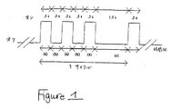
1996年以前は、煙感知器の可聴警報音は、製造会社によってパターンが異なっていた。ある可聴警報音は持続的であり、他は異なる間欠的な時間的パターンを示していた。しかしながら、1996年以降に製造された煙感知器は、煙感知器が図1に示される時間的パターンを有する可聴警報信号を発することを規定した、全国防火協会(National Fire Protection Association)の規格であるNFPA72に従うよう求められている。このパターンは、3セットの短いオン/オフ期間と、それに続く、より長いオフ期間とからなる。短いオンおよびオフ期間の長さは、「オン」が0.5秒+/−10%、続く「オフ」が0.5秒+/−10%に特定される。長いオフ期間は、1.5秒+/−10%に特定される。出願人が数個の煙感知器で行った試験によれば、すべてではないがほとんどの感知器がこの仕様を満たす。 Prior to 1996, the audible alarm sound of smoke detectors had different patterns depending on the manufacturer. Some audible alert sounds were persistent and others showed different intermittent temporal patterns. However, smoke detectors manufactured after 1996 are a National Fire Protection Association standard that stipulates that smoke detectors emit audible alarm signals having the temporal pattern shown in FIG. It is required to follow some NFPA72. This pattern consists of three sets of short on / off periods followed by longer off periods. The length of the short on and off periods are specified as “on” 0.5 seconds +/− 10%, followed by “off” 0.5 seconds +/− 10%. The long off period is specified as 1.5 seconds +/− 10%. According to tests conducted by the applicant on several smoke detectors, most if not all detectors meet this specification.
図1の時間的パターンに加えて、NFPA72はさらに、プライベートモードで動作するよう意図される可聴警報信号は以下を有しなければならないと特定している。
−可聴機器から10ftで少なくとも45dBAの音響レベル、または最小聴取距離で120dBA超の音響レベル、
−床上5ftで計測して、平均的な周囲音響レベルより少なくとも15dBA高い音響レベル、または少なくとも60秒の長さを有する最大音響レベルより5dBA高い音響レベルの、いずれか大きいレベル。
NFPA72はさらに、睡眠場所においては可聴警報信号は以下を有しなければならないと特定している。
−睡眠場所における枕のレベルで計測して、平均的な周囲の音響レベルより少なくとも15dBA高い音響レベル、または、少なくとも60秒の長さを有する最大音響レベルより5dBA高い音響レベル、または少なくとも70dBAの音響レベルの、いずれか大きいレベル。
In addition to the temporal pattern of FIG. 1, NFPA 72 further specifies that an audible alarm signal intended to operate in a private mode must have:
An acoustic level of at least 45 dBA at 10 ft from an audible device, or an acoustic level of more than 120 dBA at a minimum listening distance;
A sound level measured at 5 ft above the floor, which is at least 15 dBA higher than the average ambient sound level, or 5 dBA higher than the maximum sound level with a length of at least 60 seconds, whichever is greater.
The NFPA 72 further specifies that in sleep places, the audible alert signal should have:
-An acoustic level at least 15 dB higher than the average ambient acoustic level, or an
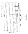
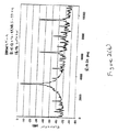
NFPA72は可聴警報音の周波数は特定していない。しかしながら、出願人は約18種の現在入手可能な煙感知器について試験を行ない、1996年以降に製造された(1996年以前に製造された数種を含む)、現在市場で入手可能な煙感知器のほとんどは、その可聴警報音が約3200Hz+/−約10%ではっきり区別される周波数ピークを有し、対応する調和(harmonic)周波数においてもピークを有することを発見した。3200Hzの周波数は、通常の聴力を有するほとんどの人に容易に聴こえる音に対応する。図2aに、典型的な煙感知器、この場合はセントリー社(Fire Sentry)の0914モデルの煙感知器において、発泡体(foam)で内張りされた箱の中で取得された、警報音の振幅対周波数の例示的なプロットが示される。図2bに、内張りのない箱の中における同じ感知器の振幅対周波数のプロットが示される。表2に、出願人が試験を行った18種の煙感知器の結果のまとめが示される。 The NFPA 72 does not specify the frequency of the audible alarm sound. However, Applicants have tested about 18 currently available smoke detectors and have been manufactured since 1996 (including some manufactured before 1996) and currently available on the market. Most of the vessels have found that the audible alarm sound has a distinct frequency peak at about 3200 Hz +/− about 10% and also has a peak at the corresponding harmonic frequency. A frequency of 3200 Hz corresponds to a sound that can be easily heard by most people with normal hearing. FIG. 2a shows the alarm sound amplitude obtained in a foam-lined box in a typical smoke detector, in this case a Fire Sentry 0914 model smoke detector. An exemplary plot of frequency versus frequency is shown. In FIG. 2b a plot of the amplitude vs. frequency of the same sensor in a box without a lining is shown. Table 2 provides a summary of the results for the 18 smoke detectors tested by the applicant.
多くの煙感知器の製造会社がほぼ10年で煙感知器を取替えるよう推奨しているので、依然稼動している1996年以前の煙感知器の数は急速に減っている。したがって、本発明は、主に1996年製およびそれより新しい煙感知器の可聴警報器を認識するというコンテキストで説明される。しかしながら、本発明はそのように限定されると理解されるべきではない。 As many smoke detector manufacturers recommend replacing smoke detectors in nearly 10 years, the number of smoke detectors still in operation prior to 1996 is rapidly decreasing. Thus, the present invention will be described primarily in the context of recognizing audible alarms made in 1996 and newer smoke detectors. However, it should not be understood that the present invention is so limited.
図3は、煙感知器の可聴警報音を感知し、第2の警報装置を作動させるための、本発明の実施例による装置300を示す。装置300は周囲の音を感知するためのマイク310を含む。マイク310は任意で増幅器320(図3では点線で示される)に接続される。増幅器320は、マイク310からのアナログ信号を周囲の音を表わすデジタル信号へ変換するための、アナログデジタル(A/D)コンバータ330に接続される。A/Dコンバータ330からのデジタル化された音データは、可聴の煙感知警報音を感知するためのプロセッサ340に入力される。プロセッサ340は、マイクロプロセッサ、デジタル信号プロセッサ、または他のいかなるタイプのプロセッサでもよい。図3ではプロセッサ340は単一の箱で示されるが、プロセッサ340は複数の装置を含み得ることが理解されるべきである。一実施例において、プロセッサ340はフーリエ変換を計算するための専用装置と汎用マイクロプロセッサとを含む。メモリ350がプロセッサ340に接続される。
FIG. 3 shows an
プロセッサ340は電源360によって動く。好ましい実施例において、電源360はバッテリである。代替として、電源は、交流電源に接続するための変換器および整流器を含んでもよい。さらに他の実施例において、電源360は、交流電源が入手可能な場合には交流電源から、交流電源が入手可能でない場合にはバッテリから、当該技術において周知の態様でプロセッサ340に電力を供給するように適合されてもよい。
The
プロセッサが煙感知器からの可聴警報音を感知すると、プロセッサ340は警報装置370に信号を出力する。警報装置370は好ましい実施例では触知性警報器である。本発明で用いられ得る触知性警報器には、振動する腕時計、振動するポケットベル、および、SONIC ALERTS(登録商標)の商標で販売されているスーパーベッドバイブレータ(Super Bed Vibrator)、速度が可変のスーパーベッドバイブレータなどのベッドシェイカがある。スーパーバイブレータは、3.5インチの直径、1.25インチの厚みを有し、不平衡
な質量とモータとを有する。この装置は、マットレスまたは枕の下に置くことができる。他の触知性警報器もまた用いることができる。
When the processor senses an audible alarm from the smoke detector, the
図4は、本発明の一実施例においてプロセッサ340によって実行される処理のフロー図400である。ステップ402において、マイク310を用いて周囲の音がある時間期間サンプリングされる。この時間期間は、いくつかの実施例では2秒と選択される。この期間は、NFPA72規格で特定される、1.5秒の長いオフ期間を超えるよう選択される。ステップ403において、プロセッサ340は、A/Dコンバータ330によって出力されたデジタル化された音データについてフーリエ変換を実行する。次にステップ404において、低周波しきい値より低い周波数のデータを消去することによりデータがフィルタされる。当業者は、ハイパスアナログフィルタをA/Dコンバータ330より前に挿入することによって、このフィルタするステップが置換され得ることを認識するであろう。
FIG. 4 is a flow diagram 400 of processing performed by the
ステップ404においてデータがフィルタされた後、ステップ406において、フィルタされたデータの最大振幅が決定される。ステップ408において、この最大振幅が煙感知警報音の予想周波数に対応する周波数、すなわち、3200Hz+/−10%(2880から3520Hz)であれば、ステップ410において取得ルーチンに入る。取得ルーチンが完了した後、またはステップ406で特定されたピークがステップ408で正しい周波数にないとき(すなわち、煙感知器以外の何らかの装置がその時点で最大の雑音を出しているとき)、プロセッサ340はステップ412においてある時間期間遅延し、ステップ402が繰返される。好ましい実施例において、ステップ412の遅延期間は10秒である。
After the data is filtered at
図4のフロー図400に示されるルーチンは、煙感知警報音が鳴っている可能性があるか否かを決定するために周期的(periodic)に実行されるモニタリングルーチンとして機能する。この文脈において「周期的」とは、時々、を意味し、固定間隔および変動する間隔の双方でルーチンを実行することを含む。2秒間のモニタリング期間および10秒間の遅延期間の選択は、約17%のデューティサイクルに対応する。代替として、連続した2秒間のモニタリング期間ではなく、1.5秒の「オフ」期間(または目標となる時間的パターンの最長のオフ期間)よりも長い期間にわたって連続して間隔をあけた、より短いサンプルが用いられてもよい。連続的なモニタリングよりも、周期的なモニタリングルーチンが電力を節約するよう実行され、それは特にバッテリで動く装置では重要である。壁のコンセントからの従来の家庭用の交流電力で動く装置など、本発明の他の実施例においては、このモニタリングルーチン400が省略されて取得ルーチン410が連続して実行されてもよい。
The routine shown in the flow diagram 400 of FIG. 4 functions as a monitoring routine that is executed periodically to determine if a smoke detection alarm may be sounding. “Periodic” in this context means from time to time and includes running routines at both fixed and variable intervals. The choice of a 2 second monitoring period and a 10 second delay period corresponds to a duty cycle of about 17%. Alternatively, instead of a continuous 2 second monitoring period, more continuously spaced over a longer period than the 1.5 second "off" period (or the longest off period of the target temporal pattern) Short samples may be used. Rather than continuous monitoring, a periodic monitoring routine is performed to save power, which is particularly important in battery-powered devices. In other embodiments of the present invention, such as a conventional household powered device from a wall outlet, the
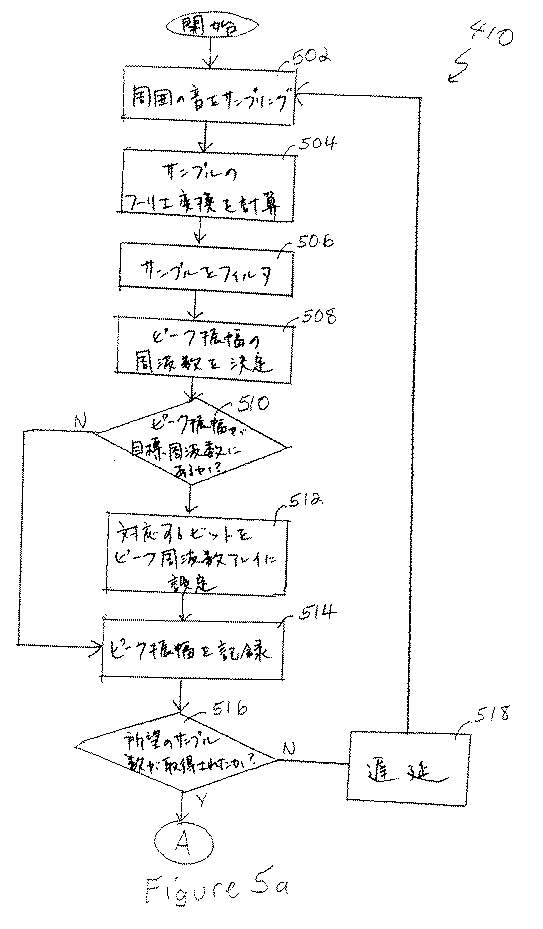
モニタリングルーチン410の詳細は図5aおよび図5bに示される。このルーチンは、ステップ502において、周囲の音を短時間期間サンプリングすることで開始する。いくつかの実施例において、このサンプリング期間は50ミリ秒である。サンプリング期間の最小の長さは、データのフーリエ変換から良好な周波数分解能を得るのに、取得されるサンプル数が十分であるように選択されなければならない。したがって、サンプリング期間の最小の長さは、ハードウェアのサンプルレートに依存する。ステップ504において、プロセッサ340はフーリエ変換を行うことによってサンプルを周波数領域に変換し、ステップ506において、サンプルは、ある周波数しきい値(好ましい実施例では500Hz)より低いデータを除外することによってハイパスでフィルタされる。次にステップ508において、ピーク振幅の周波数が決定される。ピーク振幅が煙感知警報音の予想周波数(上述のように、3200Hz+/−10%、すなわち2880Hzから3520Hz)にある場合、ステップ512において、対応するビットがメモリ350のピーク周波数アレイに設定される。さもなければ、対応するビットは「0」のままである。ピーク周
波数アレイは、好ましくはビットの一次元アレイであり、ビットの総数は総サンプル期間中のサンプル総数(たとえば12個)に等しい。ステップ512の後(または、ピーク振幅の周波数がステップ510において煙感知警報音の予想周波数でない場合、ステップ510の後)、サンプルのピーク振幅はステップ514においてメモリに記録される。
Details of the
下記にさらに説明されるように、ピーク周波数アレイはピーク振幅アレイと相関され、次に、予想される時間的パターンと比較される。これによりNFPA72パターンの各「オン」期間のピーク周波数は、煙感知器の可聴警報音の予想周波数に確実に一致する。「オフ」期間のピーク振幅の周波数が目標周波数にあるか否かは重要ではなく、煙感知警報音の目標周波数にピーク周波数を有する「オフ」期間は、結果として、宣言されない一致とはなるわけではない。なぜなら、周囲の雑音が、「オフ」期間中に、煙感知警報音と同じ周波数にピークを有する可能性があるからである。 As described further below, the peak frequency array is correlated with the peak amplitude array and then compared to the expected temporal pattern. This ensures that the peak frequency of each “on” period of the NFPA 72 pattern matches the expected frequency of the audible alarm sound of the smoke detector. It is not important whether the peak amplitude frequency of the “off” period is at the target frequency, and an “off” period having a peak frequency at the target frequency of the smoke detection alarm will result in an undeclared match. is not. This is because the ambient noise may have a peak at the same frequency as the smoke-sensing alarm during the “off” period.
ステップ514で所望のサンプル数が取得されていない場合、ステップ518においてプロセッサ340はある時間期間遅延し、ステップ502で他のサンプルが取得される。好ましい実施例において遅延期間は最後のサンプル期間の開始から0.5秒と選択され、それはNFPA72によって規定された時間的パターンの、0.5秒の「オン」期間および0.5秒の「オフ」期間に対応する。好ましい実施例ではサンプルの総数は12個と選択され、それは、サンプル期間の間に0.5秒の間隔をおいた、5.5秒の総サンプル期間と対応する。図6に示されるように、5.5秒は、NFPA72で規定される3つの「オン」期間および長い「オフ」期間、ならびに1つの追加の「オン」期間が確実に総サンプル期間内に存在するために必要となる、最小時間量に対応する。図7は、1つのあり得る可聴警報音信号の上に重畳された、12個のサンプル期間を示す。
If the desired number of samples has not been acquired at
再び図5aを参照して、ステップ516において総サンプル期間について所望のサンプル数が取得されると、ステップ518において総期間中の全サンプルの最大振幅が決定される。次に、ステップ520において、最大振幅に基づいて振幅しきい値が設定される。振幅しきい値は「オン」条件に対応するしきい値振幅を決定するのに用いられる。いくつかの実施例において、振幅しきい値は最大振幅の80%に選択される。振幅しきい値は音源(すなわち煙感知器の可聴警報音)の変動の予想振幅に依存する。したがって、振幅しきい値は、「目標」となる煙感知器の範囲および所望の誤報率に依存して異なり得る。
Referring again to FIG. 5a, once the desired number of samples is obtained for the total sample period at
振幅しきい値を最大しきい値の関数として設定することは、本発明の誤報制御にとって重要な局面であると考えられることに注意されるべきである。このしきい値の選択では、煙感知警報音の最大振幅は装置300と煙感知器との間の距離の自乗の関数として変動するので、最大振幅はわからないであろうが、煙感知警報音は「オン」期間中は一定のレベルであって、装置300と煙感知器との間の距離は通常は変化しないので、最大振幅は「オン」期間中、通常は同じであろう、と認識する。さらに、振幅しきい値は、雑音に対する最大振幅、または雑音信号に対する最大振幅の関数としてではなく、最大振幅の関数として選択されることも注意されるべきである。なぜなら、背景の雑音は変化していることがあり、そのため煙感知警報音の振幅が一定であっても信号対雑音比は一定ではないためである。この振幅しきい値は、振幅が変動する間欠音を発するテレビなど他の装置から煙感知警報音を区別することを助けるので、誤報防止に重要な役割を果たす。
It should be noted that setting the amplitude threshold as a function of the maximum threshold is considered an important aspect for false alarm control of the present invention. In this threshold selection, the maximum amplitude of the smoke detection alarm will vary as a function of the square of the distance between the
ステップ520でしきい値振幅が決定された後、ステップ522において、最大振幅がしきい値振幅を超える各サンプルについて、ピーク振幅アレイに、対応するビットが設定される。ピーク振幅アレイは、ピーク周波数アレイと同様、好ましくはビットの一次元アレイであって、ビットの総数は総サンプル期間におけるサンプル総数(たとえば12個)に等しい。例として、総サンプル期間中に感知される最大振幅が下記のようであるとする。
After the threshold amplitude is determined at
この場合において、最大振幅は9.5である。振幅しきい値は9.5×0.80=7.6である。したがって、サンプル1,3,5,9および11における振幅のみがしきい値を超え、結果としてピーク振幅アレイは101010001010となる。
In this case, the maximum amplitude is 9.5. The amplitude threshold is 9.5 × 0.80 = 7.6. Thus, only the amplitudes in
いくつかの実施例において、振幅しきい値がそれ以下に設定できない最底値がある。この最底値はNFPA72によって規定された周囲雑音レベルより15dB高いレベルに対応する。しかしながらこの最小値15dBは、建物に応じて正しい数の煙感知器が設置されている(すなわち煙感知器が最大許容距離内にある)と仮定している。他の実施例においては、このような規格外の設置に合わせて最小値は10dBにすぎない。この最小振幅しきい値は、周囲の雑音によって誤報がトリガされないことを確実にする。 In some embodiments, there is a bottom value that the amplitude threshold cannot be set below. This bottom value corresponds to a level 15 dB above the ambient noise level defined by NFPA 72. However, this minimum value of 15 dB assumes that the correct number of smoke detectors are installed according to the building (ie the smoke detector is within the maximum allowable distance). In other embodiments, the minimum value is only 10 dB for such non-standard installations. This minimum amplitude threshold ensures that false alarms are not triggered by ambient noise.
次にステップ524において、ピーク振幅アレイはピーク周波数アレイと相関される。上述のように、ピーク周波数アレイはビットのアレイであって、最大振幅が3200Hzの周波数に対応している各サンプルについて、1つの1を有する。好ましい実施例において、この相関関係は、ピーク周波数アレイおよびピーク振幅アレイのビット単位のANDを取ることを含む。相関するアレイも、サンプル数と等しい数のビットを有する一次元アレイであり、ピーク振幅が振幅しきい値を超え、AND(かつ)、煙感知器の予想周波数と一致する周波数、すなわち約3200Hzにピーク振幅がある各サンプルについて、1つのビットが設定される。低雑音環境において、ピーク周波数アレイおよびピーク振幅アレイは一致し得る。しかしながら、それは常に起こるわけではない。たとえば、出願人が実際に行った試験によると、ピーク周波数アレイでは、ピーク振幅アレイにおいてはビットが設定されないサンプルについてビットが設定され得る、ということが明らかとなった。これは、NFPA72の時間的パターンにおける「オフ」期間中に感知される、煙感知警報音と当然同じ周波数を有する「オン」期間からのわずかな反響によると考えられる。ピーク周波数アレイとピーク振幅アレイとを相関させることで、これらの反響が「オン」信号と誤認されることを防ぐ。
Next, at
次にステップ526において、相関後のアレイがNFPA72の時間的パターンと比較される。上述のように、サンプルの総期間は、NFPA72の時間的パターンの「オン」期間が少なくとも4つあるように選択される。4つの「オン」期間のうち3つは0.5秒の「オフ」期間によって分離され、他の「オン」期間は1.5秒の「オフ」期間によって分離される。しかしながら、3つの「オン」期間が4つ目の「オン」期間に先立つかどうかはわからない。したがって、これらの4つの「オン」期間に対応する2つのあり得るパ
ターンは以下のようになる(ここで1は「オン」を示し、0は「オフ」を示す):(a)100010101、または(b)101010001。したがって、これら2つのあり得る9ビットのパターンの各々は、12ビットの相関アレイと、12ビットアレイの第1、第2、第3および第4のビットを開始位置として比較される(換言すると、パターンは、相関アレイの最初の4ビットのいずれからも開始し得る)。ステップ526においていずれかのパターンが相関アレイ内で見つかると、ステップ528において警告装置が作動される。
Next, in
ピーク周波数アレイとは異なり、ピーク振幅アレイが、NFPA72の時間的パターンの「オフ」期間に対応するサンプル中で「オフ」を示すことが重要である。ピーク周波数アレイ(ここでは「オフ」期間に対応するサンプルの状態は重要ではない)をピーク振幅アレイとANDすることで、2つのアレイをNFPAの時間的パターンと比較することが容易になる。 Unlike the peak frequency array, it is important that the peak amplitude array show “off” in the sample corresponding to the “off” period of the NFPA 72 temporal pattern. ANDing the peak frequency array (here, the state of the sample corresponding to the “off” period is not important) with the peak amplitude array makes it easy to compare the two arrays to the temporal pattern of NFPA.
これらの2つのパターンが、NFPA72に規定されるパターンの完全な1「期間」よりも多くを含むことに注意されるべきである。これはすなわち、NFPA72のパターンの完全な1期間が含む「オン」期間は3つのみであるということである。上記のパターンにおける第4の「オン」期間は、NFPA72のパターンの第2の期間に対応し、これは、誤報防止のための追加の方策を提供するために含まれている。いくつかの実施例において、第4の「オン」期間は目標のパターンに含まれない。 It should be noted that these two patterns contain more than the full one “period” of the pattern defined in NFPA 72. This means that a complete period of the NFPA 72 pattern includes only three “on” periods. The fourth “on” period in the above pattern corresponds to the second period of the NFPA 72 pattern, which is included to provide an additional measure to prevent false alarms. In some embodiments, the fourth “on” period is not included in the target pattern.
ステップ526においてパターンが相関アレイ内で見つからない場合、ステップ530において、試行の総回数が、相関試行しきい値の総数と比較される。好ましい実施例において、相関試行しきい値の総回数は10回と選択される。したがって、プロセッサ340は、5.5秒の期間を10回にわたり、合計55秒、すなわち約1分間にわたって、時間的パターンを見つけるよう試行する。ステップ530において相関試行しきい値の総回数が達成されていない場合、ステップ502以降が繰返される。ステップ530において相関試行しきい値の総数が達成されるとサブルーチンは終了し、制御はステップ412(図4)に戻る。
If the pattern is not found in the correlation array at
上述のように、装置300は1996年以前の煙感知器を感知するためにも用いられ得る。たとえば、1996年以前のいくつかの煙感知器は、一連のオンおよびオフのパルスからなる時間的パターンで可聴警報音を発する。このような煙感知器を感知するために、サンプルレートはオン/オフのパルスのタイミングに対応するよう調整され、ステップ526のパターンは1と0とが交代する数列に変更される。他の1996年以前の煙感知器は連続的な音を発する。これらの感知器については、パターンは1の数列に変更される。単一の1(すなわち、振幅しきい値より高い振幅を有する単一のサンプル)ではなく1の数列が用いられ、いずれの信号の持続時間も確実に、短い、短期の音(たとえばテレビの音)が煙感知器の可聴警報音と誤認されるのを防ぐために十分に長くされる。
As mentioned above, the
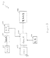
図8は、本発明の第2の実施例による煙感知器800を示す。煙感知器800は、従来の煙感知器と類似の態様で壁または天井に設置するのに適している。しかしながら、下記にさらに詳細に述べるように、煙感知器800は、遠隔の触知性警報の作動および局から局への作動ができるよう適合される。
FIG. 8 shows a
煙感知器800は、増幅器820に接続されるマイク810を含む。増幅器820はA/Dコンバータ830に接続される。A/Dコンバータ830はプロセッサ840に接続される。プロセッサ840は、上述の態様で、A/Dコンバータ830からのデジタル化された音のサンプル内の可聴警報音を感知するよう構成される。同様に、メモリ850および電源860は、図3のメモリ350および電源360と同じ機能を実行する。
煙感知器800は、プロセッサ840に接続される煙感知回路805をさらに含む。煙感知回路は当該技術で知られるいかなる従来の型でもよい。同じくプロセッサ840に接続されるのは、他の煙感知器(図8では示されない)と通信することが可能な送受信機880(典型的にはRF送受信機)である。プロセッサ840が他の煙感知器(図8では示されない)からの可聴警報音を感知するか、または、煙感知回路805が火災を感知すると、または、他の煙感知器から送受信機880を介して作動が受取られると、プロセッサ840は可聴の(および/または可視性の)警報器895を鳴らす。加えて、プロセッサ840は、触知性警報装置870および追加の煙感知器890に対して作動メッセージを発信する。
煙感知器800のプロセッサ840は、他の煙感知器から送受信機880を介して作動メッセージを受取ったとき、または他の煙感知器の可聴警報音が感知されたとき、警報装置870および895を作動させる。代替的な実施例において、警報装置870および895が作動するにはそれら双方の条件が満たされなければならない。これは誤報を減じることに役立つが、感知器800が、RF、または聴覚的な干渉から、より影響を受けやすくする。
The processor 840 of the
他の感知器から作動メッセージを受取るとすぐ作動メッセージを送ることが望ましいということを、当業者は理解するであろう。なぜならそれは、3つ以上の感知器が1つの場所に設置されている場合に、感知器800が中継機として作動することを可能にするからである。したがって、たとえば第1の煙感知器は、感知器800に受取られるが第3の煙感知器には受取られない作動メッセージを送り得る。この場合、第1の感知器から作動メッセージを受取ってすぐ感知器800が送った作動メッセージが、第3の感知器に達し得る。
One skilled in the art will appreciate that it is desirable to send an activation message as soon as it receives an activation message from another sensor. This is because when more than two sensors are installed at one location, the
いくつかの実施例においては、煙感知器800は図8のすべての構成要素を含むわけではないことが理解されるべきである。たとえば、煙感知器800は、聴覚障害者に対して警告する必要がない場合には触知性警報装置870とともには用いられない。このような実施例は、配線を必要とせずに局から局への作動を提供する目的で用いられ得る。さらに、このような実施例は、他の感知器からの可聴警報音を感知するためのマイク810、増幅器820およびA/Dコンバータ830を含まなくてもよく、その代わり、他の感知器からのRF作動信号および煙感知回路805に依存して作動が引起され得る。代替として、他の実施例は、送受信機880を介して他の感知器から作動装置を受取るよう適合されておらず、その代わり、煙感知回路805および/または他の感知器からの可聴警報音の感知に依存して、可聴警報器895および触知性警報器870をトリガする。
It should be understood that in some embodiments,
本発明は、煙感知器と、煙感知器の可聴警報音を感知する方法および装置との具体的な実施例を参照して説明されたが、当業者によれば本発明の精神を逸脱することなく多くの変形および変更がなされ得ることが理解されるであろう。したがって、付随する請求項によって本発明の真の精神および範囲の中にあるこのようなすべての変形および変更を網羅することが意図される。 Although the present invention has been described with reference to specific embodiments of smoke detectors and methods and apparatus for sensing audible alarm sounds of smoke detectors, those skilled in the art will depart from the spirit of the invention. It will be understood that many variations and modifications may be made without it. Accordingly, the appended claims are intended to cover all such modifications and changes as fall within the true spirit and scope of the invention.
Claims (14)
複数のサンプル期間の各々のピーク振幅を感知するステップを含み、サンプル期間の各々は単一の警報期間における予想されたオンまたはオフ期間のうち1つと対応し、さらに、
ピーク振幅から最大ピーク振幅を選択するステップと、
振幅しきい値を設定するステップとを含み、振幅しきい値は最大ピーク振幅の関数であり、さらに、
いずれのサンプル期間が振幅しきい値を超えるピーク振幅を有するかを決定するために、サンプル期間の各々についてピーク振幅の各々と振幅しきい値とを比較するステップと、
ピーク振幅が振幅しきい値を超えるサンプル期間の時間的パターンが、予め決定された時間的パターンと一致するか否かに少なくとも部分的に基づいて、可聴警報が活性であるか否かを決定するステップとを含む、方法。A method for sensing whether an audible alarm generated by a smoke detector is active, the audible alarm comprising a plurality of on periods and a plurality of off periods arranged in a predetermined temporal pattern Each of the on periods is a period in which an audible alarm sound is generated by the smoke sensor, and each of the off periods is a period in which no audible sound is generated by the smoke sensor, the method comprising:
Sensing the peak amplitude of each of the plurality of sample periods, each of the sample periods corresponding to one of the expected on or off periods in a single alarm period;
Selecting the maximum peak amplitude from the peak amplitude;
Setting an amplitude threshold, the amplitude threshold being a function of the maximum peak amplitude, and
Comparing each of the peak amplitudes to the amplitude threshold for each of the sample periods to determine which sample period has a peak amplitude that exceeds the amplitude threshold;
Determining whether an audible alert is active based at least in part on whether the temporal pattern of the sample period where the peak amplitude exceeds the amplitude threshold matches a predetermined temporal pattern Including a step.
決定するステップは、予め決定された時間的パターンのオン期間に対応するサンプル期間の各々のピーク振幅に対応する周波数が、可聴警報音の各々が生成される警報音周波数に対応するか否かにさらに基づく、請求項1に記載の方法。Determining the frequency corresponding to the peak amplitude of each of the sample periods corresponding to the on period of the predetermined temporal pattern;
The step of determining whether the frequency corresponding to the peak amplitude of each of the sample periods corresponding to the on period of the predetermined temporal pattern corresponds to the alarm sound frequency at which each of the audible alarm sounds is generated. The method of claim 1 further based.
可聴警報音が存在するか否かを決定するために、周囲音サンプルのパラメータを検査するステップと、
可聴警報音が存在し得る可能性がない場合には、ある時間期間だけ遅延して、得るステップおよび検査するステップを繰り返すステップとをさらに含み、
感知するステップ、設定するステップ、選択するステップ、比較するステップ、および決定するステップは、可聴警報音が存在し得る可能性があるときに実行される、請求項1に記載の方法。Obtaining an ambient sound sample prior to the sensing step;
Examining the parameters of the ambient sound sample to determine whether an audible alert sound is present;
If there is no possibility that an audible audible alarm may be present, the method further includes the steps of delaying by a period of time, and repeating the obtaining and examining steps;
The method of claim 1, wherein the sensing, setting, selecting, comparing, and determining steps are performed when an audible audible alert may be present.
マイクと、
マイクに接続されるプロセッサとを含み、
プロセッサは、
複数のサンプル期間の各々のピーク振幅を感知するステップを実行し、サンプル期間の各々は単一の警報期間における予想されたオンまたはオフ期間のうち1つと対応し、さらに、
ピーク振幅から最大ピーク振幅を選択するステップと、
振幅しきい値を設定するステップとを実行し、振幅しきい値は最大ピーク振幅の関数であり、さらに、
いずれのサンプル期間が振幅しきい値を超えるピーク振幅を有するかを決定するために、サンプル期間の各々についてピーク振幅の各々と振幅しきい値とを比較するステップと、
ピーク振幅が振幅しきい値を超えるサンプル期間の時間的パターンが、予め決定された時間的パターンと一致するか否かに少なくとも部分的に基づいて、可聴警報が活性であるか否かを決定するステップとを実行するよう構成される、装置。An apparatus for sensing whether an audible alarm generated by a smoke sensor is active, wherein the audible alarm is arranged in a plurality of on periods and a plurality of off periods arranged in a predetermined temporal pattern. Each of the on periods is a period in which an audible alarm sound is generated by the smoke sensor, and each of the off periods is a period in which no audible sound is generated by the smoke sensor,
With a microphone,
A processor connected to a microphone,
Processor
Sensing the peak amplitude of each of the plurality of sample periods, each of the sample periods corresponding to one of the expected on or off periods in a single alarm period;
Selecting the maximum peak amplitude from the peak amplitude;
Setting an amplitude threshold, wherein the amplitude threshold is a function of the maximum peak amplitude;
Comparing each of the peak amplitudes to the amplitude threshold for each of the sample periods to determine which sample period has a peak amplitude that exceeds the amplitude threshold;
Determining whether an audible alert is active based at least in part on whether the temporal pattern of the sample period where the peak amplitude exceeds the amplitude threshold matches a predetermined temporal pattern An apparatus configured to perform the steps.
予め決定された時間的パターンのオン期間に対応するサンプル期間の各々のピーク振幅に対応する周波数を決定するステップを実行するようさらに構成され、
決定するステップは、予め決定された時間的パターンのオン期間に対応するサンプル期間の各々のピーク振幅に対応する周波数が、可聴警報音の各々が生成される警報音周波数に対応するか否かにさらに基づく、請求項8に記載の装置。Processor
Further configured to perform a step of determining a frequency corresponding to each peak amplitude of the sample period corresponding to an on period of the predetermined temporal pattern;
The step of determining whether the frequency corresponding to the peak amplitude of each of the sample periods corresponding to the on period of the predetermined temporal pattern corresponds to the alarm sound frequency at which each of the audible alarm sounds is generated. 9. The apparatus according to claim 8, further based.
感知するステップの前に周囲音サンプルを得るステップと、
可聴警報音が存在するか否かを決定するために、周囲音サンプルのパラメータを検査するステップと、
可聴警報音が存在し得る可能性がない場合には、ある時間期間だけ遅延して、得るステップおよび検査するステップを繰り返すステップとを実行するようさらに構成され、
感知するステップ、設定するステップ、選択するステップ、比較するステップ、および決定するステップは、可聴警報音が存在し得る可能性があるときに実行される、請求項8に記載の装置。Processor
Obtaining an ambient sound sample prior to the sensing step;
Examining the parameters of the ambient sound sample to determine whether an audible alert sound is present;
If there is no possibility that an audible audible alarm may be present, further configured to perform a step of delaying for a period of time and repeating the steps of obtaining and examining
9. The apparatus of claim 8, wherein the sensing, setting, selecting, comparing, and determining steps are performed when an audible audible alarm may be present.
Applications Claiming Priority (2)
| Application Number | Priority Date | Filing Date | Title |
|---|---|---|---|
| US41512702P | 2002-10-02 | 2002-10-02 | |
| PCT/US2003/031128 WO2004032078A2 (en) | 2002-10-02 | 2003-10-02 | Method and apparatus for indicating activation of a smoke detector alarm |
Publications (3)
| Publication Number | Publication Date |
|---|---|
| JP2006502483A JP2006502483A (en) | 2006-01-19 |
| JP2006502483A5 JP2006502483A5 (en) | 2006-11-16 |
| JP4279255B2 true JP4279255B2 (en) | 2009-06-17 |
Family
ID=32069814
Family Applications (1)
| Application Number | Title | Priority Date | Filing Date |
|---|---|---|---|
| JP2004542013A Expired - Lifetime JP4279255B2 (en) | 2002-10-02 | 2003-10-02 | Method and apparatus for signaling activation of a smoke detection alarm |
Country Status (15)
| Country | Link |
|---|---|
| US (1) | US7015807B2 (en) |
| EP (1) | EP1547041B1 (en) |
| JP (1) | JP4279255B2 (en) |
| AT (1) | ATE369598T1 (en) |
| BR (2) | BRPI0315050B1 (en) |
| CA (1) | CA2501140C (en) |
| DE (1) | DE60315482T2 (en) |
| DK (1) | DK1547041T3 (en) |
| ES (1) | ES2291707T3 (en) |
| IL (1) | IL167827A (en) |
| MX (1) | MXPA05003527A (en) |
| NO (1) | NO331226B1 (en) |
| NZ (1) | NZ539363A (en) |
| WO (1) | WO2004032078A2 (en) |
| ZA (1) | ZA200503069B (en) |
Families Citing this family (68)
| Publication number | Priority date | Publication date | Assignee | Title |
|---|---|---|---|---|
| US20070096931A1 (en) * | 2003-12-22 | 2007-05-03 | Runciman Dunstan W | Alarm device |
| US7148797B2 (en) * | 2004-07-23 | 2006-12-12 | Innovalarm Corporation | Enhanced fire, safety, security and health monitoring and alarm response method, system and device |
| US7170404B2 (en) * | 2004-07-23 | 2007-01-30 | Innovalarm Corporation | Acoustic alert communication system with enhanced signal to noise capabilities |
| US7173525B2 (en) * | 2004-07-23 | 2007-02-06 | Innovalarm Corporation | Enhanced fire, safety, security and health monitoring and alarm response method, system and device |
| WO2006012460A2 (en) * | 2004-07-23 | 2006-02-02 | Innovalarm Corporation | Enhanced acoustic monitoring and alarm response |
| US7129833B2 (en) * | 2004-07-23 | 2006-10-31 | Innovalarm Corporation | Enhanced fire, safety, security and health monitoring and alarm response method, system and device |
| US7126467B2 (en) | 2004-07-23 | 2006-10-24 | Innovalarm Corporation | Enhanced fire, safety, security, and health monitoring and alarm response method, system and device |
| US7656287B2 (en) * | 2004-07-23 | 2010-02-02 | Innovalarm Corporation | Alert system with enhanced waking capabilities |
| WO2006010197A1 (en) * | 2004-07-30 | 2006-02-02 | Elmar Trefz | System and apparatus for alerting a user in response to environmental conditions |
| US8248226B2 (en) * | 2004-11-16 | 2012-08-21 | Black & Decker Inc. | System and method for monitoring security at a premises |
| US7170397B2 (en) * | 2004-12-03 | 2007-01-30 | Combustion Science & Engineering, Inc. | Method and apparatus for waking a person |
| US7644078B2 (en) * | 2005-02-28 | 2010-01-05 | Gm Global Technology Operations, Inc. | System and method for mining of temporal data |
| US7319402B1 (en) * | 2006-01-26 | 2008-01-15 | Sudderth Randy D | Combined doorbell and smoke detection device |
| US7501958B2 (en) * | 2006-07-12 | 2009-03-10 | Innovalarm Corporation | Strobe light alarm detection and alert system |
| US7852971B2 (en) * | 2006-07-21 | 2010-12-14 | Qualcomm, Incorporated | False channel detection for wireless communication |
| US8155326B2 (en) * | 2007-10-09 | 2012-04-10 | Schweitzer Engineering Laboratories, Inc. | System, method, and apparatus for using the sound signature of a device to determine its operability |
| US7733235B2 (en) * | 2007-10-30 | 2010-06-08 | Herbert Baker | Wireless smoke and fire detection system and method |
| JP2010061423A (en) * | 2008-09-04 | 2010-03-18 | Nittan Co Ltd | Fire alarm for dwelling house |
| GB0909077D0 (en) * | 2009-05-27 | 2009-07-01 | Wilson Derek A | Safety device |
| US8269625B2 (en) * | 2009-07-29 | 2012-09-18 | Innovalarm Corporation | Signal processing system and methods for reliably detecting audible alarms |
| US20110102133A1 (en) * | 2009-11-03 | 2011-05-05 | Thomas G. Shaffer | Programmable security system with transmitter |
| CN102109594B (en) * | 2009-12-28 | 2014-04-30 | 深圳富泰宏精密工业有限公司 | System and method for sensing and notifying voice |
| US8242899B2 (en) * | 2010-02-09 | 2012-08-14 | InnovAlaem Corporation | Supplemental alert generation device for retrofit applications |
| US8237577B2 (en) * | 2010-02-09 | 2012-08-07 | Innovalarm Corporation | Supplemental alert generation device |
| US8558708B2 (en) | 2010-02-09 | 2013-10-15 | Innovalarm Corporation | Supplemental alert generation device with speaker enclosure assembly |
| US20110234396A1 (en) * | 2010-03-24 | 2011-09-29 | Safeawake, Llc | Fire and emergency warning and locator system |
| US20140098445A1 (en) | 2011-08-17 | 2014-04-10 | Donald Randolph Hooper | Signal Activated Circuit Interrupter |
| US9846413B2 (en) | 2011-09-08 | 2017-12-19 | Fire Avert, Llc. | Safety shut-off device and method of use |
| US8836522B2 (en) * | 2011-09-08 | 2014-09-16 | Fire Avert, Llc | Safety shut-off device and method of use |
| KR101255657B1 (en) * | 2012-08-23 | 2013-04-17 | (주)건융아이비씨 | Fire alarm system for hearing-impaired person |
| US9130945B2 (en) | 2012-10-12 | 2015-09-08 | Schweitzer Engineering Laboratories, Inc. | Detection and response to unauthorized access to a communication device |
| US9087447B2 (en) | 2013-02-05 | 2015-07-21 | Encore Controls, Llc | Method and apparatus for detecting a hazard alarm signal |
| US20140257588A1 (en) * | 2013-03-06 | 2014-09-11 | LifeSmart Electronics, LLC | Appliance Shut-Off Device and Method |
| US9852656B2 (en) | 2014-01-13 | 2017-12-26 | Barbara Ander | Alarm monitoring system |
| US10274908B2 (en) | 2014-01-13 | 2019-04-30 | Barbara Ander | System and method for alerting a user |
| US9685052B2 (en) | 2014-01-13 | 2017-06-20 | Alexis Ander Kashar | System and method for alerting a user |
| US10600291B2 (en) | 2014-01-13 | 2020-03-24 | Alexis Ander Kashar | System and method for alerting a user |
| US8917186B1 (en) * | 2014-03-04 | 2014-12-23 | State Farm Mutual Automobile Insurance Company | Audio monitoring and sound identification process for remote alarms |
| US9858784B2 (en) | 2014-09-29 | 2018-01-02 | Roost, Inc. | Battery-powered device having a battery and loud sound detector using passive sensing |
| US9865157B2 (en) | 2014-09-09 | 2018-01-09 | Adt Us Holdings, Inc. | Device interface for alarm monitoring systems |
| US9852620B1 (en) * | 2014-09-19 | 2017-12-26 | Thomas John Hoeft | System and method for detecting sound and performing an action on the detected sound |
| CN104269011A (en) * | 2014-09-26 | 2015-01-07 | 珠海保税区光联通讯技术有限公司 | Sound wave and temperature sensor and working method thereof |
| US9754465B2 (en) * | 2014-10-30 | 2017-09-05 | International Business Machines Corporation | Cognitive alerting device |
| CN104332079A (en) * | 2014-11-26 | 2015-02-04 | 重庆欧派信息科技有限责任公司 | Wall-mounted type fire alarm virtual science popularization experience terminal |
| TW201709155A (en) * | 2015-07-09 | 2017-03-01 | 美高森美半導體美國公司 | Acoustic alarm detector |
| AT517657B1 (en) * | 2015-09-08 | 2021-08-15 | Siemens Mobility Austria Gmbh | Method and device for warning road users for a rail vehicle by means of sound or light signals |
| CN109074707B (en) | 2016-04-20 | 2020-07-03 | 美高森美半导体(美国)股份有限公司 | Glass breakage detection system |
| US9772671B1 (en) * | 2016-07-07 | 2017-09-26 | Climax Technology Co., Ltd. | Low-power alarm detector |
| US9836947B1 (en) * | 2016-08-02 | 2017-12-05 | Ecolink Intelligent Technology, Inc. | Method and apparatus for detecting a hazard detector signal in the presence of interference |
| US11151853B2 (en) | 2016-11-11 | 2021-10-19 | Carrier Corporation | High sensitivity fiber optic based detection |
| CN109964259B (en) | 2016-11-11 | 2022-03-25 | 开利公司 | Detection based on high sensitivity fiber |
| WO2018089668A2 (en) | 2016-11-11 | 2018-05-17 | Carrier Corporation | High sensitivity fiber optic based detection |
| CA3043500A1 (en) | 2016-11-11 | 2018-05-17 | Carrier Corporation | High sensitivity fiber optic based detection |
| CA3043587A1 (en) | 2016-11-11 | 2018-05-17 | Carrier Corporation | High sensitivity fiber optic based detection |
| EP3349195A1 (en) * | 2017-01-16 | 2018-07-18 | Repsol, S.A. | Device for reporting alarm produced by a portable gas detector |
| WO2019222785A1 (en) * | 2018-05-21 | 2019-11-28 | Ristovski Sash | Sleep safe alarm device |
| CN110009863A (en) * | 2019-04-19 | 2019-07-12 | 汉威科技集团股份有限公司 | A kind of vertical double light path smoke detection labyrinth and its detection method |
| DE102020112575A1 (en) | 2020-05-08 | 2021-11-11 | Your Home Guides GmbH | Device and method for the detection of acoustic events, in particular acoustic information and / or warning signals |
| EP4232781A1 (en) * | 2020-10-20 | 2023-08-30 | Google LLC | Barometer adaptive sampling by tight integration with other sensors and actuators |
| US11756531B1 (en) | 2020-12-18 | 2023-09-12 | Vivint, Inc. | Techniques for audio detection at a control system |
| US12026243B2 (en) | 2021-02-19 | 2024-07-02 | Johnson Controls Tyco IP Holdings LLP | Facial recognition by a security / automation system control panel |
| US11961377B2 (en) | 2021-02-19 | 2024-04-16 | Johnson Controls Tyco IP Holdings LLP | Security / automation system control panel with acoustic signature detection |
| US12361807B2 (en) | 2021-02-19 | 2025-07-15 | Tyco Fire & Security Gmbh | Security / automation system control panel graphical user interface |
| US12022574B2 (en) | 2021-02-19 | 2024-06-25 | Johnson Controls Tyco IP Holdings LLP | Security / automation system with cloud-communicative sensor devices |
| US12046121B2 (en) | 2021-02-19 | 2024-07-23 | Johnson Controls Tyco IP Holdings LLP | Security / automation system control panel with short range communication disarming |
| EP4057247A1 (en) | 2021-03-08 | 2022-09-14 | Carrier Corporation | A method of fire detector cover detection and corresponding fire detection apparatus |
| WO2022234636A1 (en) * | 2021-05-07 | 2022-11-10 | 日本電気株式会社 | Signal processing device, signal processing method, signal processing system, and computer-readable storage medium |
| US12112610B2 (en) | 2022-12-29 | 2024-10-08 | The Adt Security Corporation | Audible alarm signal detectors |
Family Cites Families (32)
| Publication number | Priority date | Publication date | Assignee | Title |
|---|---|---|---|---|
| US4227191A (en) * | 1978-02-21 | 1980-10-07 | Samuel Raber | Light emitting smoke detector |
| JPS6014399B2 (en) * | 1978-05-04 | 1985-04-12 | ホーチキ株式会社 | Physical change monitoring device |
| US4220857A (en) * | 1978-11-01 | 1980-09-02 | Systron-Donner Corporation | Optical flame and explosion detection system and method |
| US4287509A (en) * | 1979-03-26 | 1981-09-01 | Beggs Daniel H | Sound and light signaling system |
| US4365238A (en) * | 1979-06-08 | 1982-12-21 | Adam Kollin | Visual signalling apparatus |
| US4250500A (en) * | 1979-10-22 | 1981-02-10 | Rca Corporation | Smoke detector |
| US4297677A (en) * | 1979-12-10 | 1981-10-27 | John S. Lewis | Personal ambient sound referenced annunciator |
| US4380759A (en) * | 1980-11-05 | 1983-04-19 | Jerome Sulkoski | Apparatus to alert a deaf person |
| US4438428A (en) * | 1981-02-20 | 1984-03-20 | Omnitronics Research Corporation | Multiple function personal security alarm |
| US4417235A (en) * | 1981-03-24 | 1983-11-22 | Del Grande Donald J | Audible alarm network |
| US4853674A (en) * | 1986-07-21 | 1989-08-01 | Kiss Michael Z | Signalling apparatus for hearing impaired persons |
| US4777474A (en) * | 1987-03-26 | 1988-10-11 | Clayton Jack A | Alarm system for the hearing impaired |
| US4956866A (en) * | 1989-06-30 | 1990-09-11 | Sy/Lert System Ltd. | Emergency signal warning system |
| US5012223A (en) * | 1990-02-23 | 1991-04-30 | Black & Decker, Inc. | Sound activated device and method |
| WO1992002913A1 (en) * | 1990-07-27 | 1992-02-20 | Hill James L | Sound detection system |
| US6094134A (en) * | 1994-05-09 | 2000-07-25 | Audiogard International | Device for the verification of an alarm |
| US5666331A (en) * | 1994-09-20 | 1997-09-09 | Rhk Technology, Inc. | Alarm clock |
| US5651070A (en) * | 1995-04-12 | 1997-07-22 | Blunt; Thomas O. | Warning device programmable to be sensitive to preselected sound frequencies |
| US5691703A (en) * | 1995-06-07 | 1997-11-25 | Hughes Associates, Inc. | Multi-signature fire detector |
| US5686884A (en) * | 1996-01-03 | 1997-11-11 | Larkin; Dennis S. | Supervised alarm system |
| US5898369A (en) * | 1996-01-18 | 1999-04-27 | Godwin; Paul K. | Communicating hazardous condition detector |
| US5790050A (en) * | 1996-06-25 | 1998-08-04 | Parker; Peter | Method and apparatus for a signal translator |
| US5867105A (en) * | 1996-10-21 | 1999-02-02 | Hajel; William F. | Wireless alarm system |
| US5745040A (en) * | 1996-10-23 | 1998-04-28 | Loughridge; Lisa M. | Outdoor alerting device for smoke alarms |
| US5917420A (en) * | 1997-01-28 | 1999-06-29 | Gonzalez; Antonio | Smoke/fire detector for the hearing impaired |
| US5990797A (en) * | 1997-03-04 | 1999-11-23 | Bkk Brands, Inc. | Ultraloud smoke detector |
| US5999089A (en) * | 1997-05-13 | 1999-12-07 | Carlson; Lance K. | Alarm system |
| US5889468A (en) * | 1997-11-10 | 1999-03-30 | Banga; William Robert | Extra security smoke alarm system |
| US6087960A (en) * | 1998-06-24 | 2000-07-11 | Mitsubishi Electric Engineering Company, Limited | Accident sound detection circuit |
| US6420973B2 (en) * | 1999-01-23 | 2002-07-16 | James Acevedo | Wireless smoke detection system |
| GB9912133D0 (en) * | 1999-05-26 | 1999-07-28 | Evets Communications Ltd | Alarm system |
| US6384724B1 (en) * | 1999-12-22 | 2002-05-07 | Andre M Landais | Smoke alarm |
-
2003
- 2003-10-02 ES ES03774522T patent/ES2291707T3/en not_active Expired - Lifetime
- 2003-10-02 DK DK03774522T patent/DK1547041T3/en active
- 2003-10-02 US US10/676,779 patent/US7015807B2/en not_active Expired - Lifetime
- 2003-10-02 BR BRPI0315050A patent/BRPI0315050B1/en unknown
- 2003-10-02 JP JP2004542013A patent/JP4279255B2/en not_active Expired - Lifetime
- 2003-10-02 NZ NZ539363A patent/NZ539363A/en not_active IP Right Cessation
- 2003-10-02 BR BR0315050-0A patent/BR0315050A/en active IP Right Grant
- 2003-10-02 AT AT03774522T patent/ATE369598T1/en not_active IP Right Cessation
- 2003-10-02 WO PCT/US2003/031128 patent/WO2004032078A2/en not_active Ceased
- 2003-10-02 MX MXPA05003527A patent/MXPA05003527A/en active IP Right Grant
- 2003-10-02 EP EP03774522A patent/EP1547041B1/en not_active Expired - Lifetime
- 2003-10-02 DE DE60315482T patent/DE60315482T2/en not_active Expired - Lifetime
- 2003-10-02 ZA ZA200503069A patent/ZA200503069B/en unknown
- 2003-10-02 CA CA2501140A patent/CA2501140C/en not_active Expired - Lifetime
-
2005
- 2005-04-05 IL IL167827A patent/IL167827A/en unknown
- 2005-04-29 NO NO20052117A patent/NO331226B1/en not_active IP Right Cessation
Also Published As
| Publication number | Publication date |
|---|---|
| MXPA05003527A (en) | 2005-07-22 |
| DE60315482D1 (en) | 2007-09-20 |
| ZA200503069B (en) | 2006-11-29 |
| ES2291707T3 (en) | 2008-03-01 |
| NZ539363A (en) | 2006-04-28 |
| WO2004032078A2 (en) | 2004-04-15 |
| ATE369598T1 (en) | 2007-08-15 |
| NO331226B1 (en) | 2011-11-07 |
| IL167827A (en) | 2009-07-20 |
| NO20052117D0 (en) | 2005-04-29 |
| NO20052117L (en) | 2005-04-29 |
| US20040145467A1 (en) | 2004-07-29 |
| EP1547041B1 (en) | 2007-08-08 |
| EP1547041A4 (en) | 2005-11-02 |
| CA2501140A1 (en) | 2004-04-15 |
| US7015807B2 (en) | 2006-03-21 |
| DE60315482T2 (en) | 2008-04-30 |
| AU2003282904A1 (en) | 2004-04-23 |
| HK1080593A1 (en) | 2006-04-28 |
| BR0315050A (en) | 2005-08-16 |
| EP1547041A2 (en) | 2005-06-29 |
| BRPI0315050B1 (en) | 2018-09-18 |
| JP2006502483A (en) | 2006-01-19 |
| DK1547041T3 (en) | 2007-12-10 |
| CA2501140C (en) | 2010-04-13 |
| WO2004032078A3 (en) | 2004-08-12 |
Similar Documents
| Publication | Publication Date | Title |
|---|---|---|
| JP4279255B2 (en) | Method and apparatus for signaling activation of a smoke detection alarm | |
| US4450436A (en) | Acoustic alarm repeater system | |
| US6323780B1 (en) | Communicative environmental alarm system with voice indication | |
| US7170404B2 (en) | Acoustic alert communication system with enhanced signal to noise capabilities | |
| US9087447B2 (en) | Method and apparatus for detecting a hazard alarm signal | |
| US8830059B2 (en) | Facility and method for monitoring a defined, predetermined area using at least one acoustic sensor | |
| US8622147B1 (en) | Sound based fire alarm system and method | |
| CA2437531C (en) | Apparatus and method for providing alarm synchronization among multiple alarm devices | |
| US10733875B2 (en) | Detection device, information input device, and watching system | |
| AU4938300A (en) | Alarm system | |
| AU2003282904B2 (en) | Method and apparatus for indicating activation of a smoke detector alarm | |
| HK1080593B (en) | Method and apparatus for indicating activation of a smoke detector alarm | |
| GB2472466A (en) | System for assisting the rescue of vulnerable persons | |
| EP0403245A2 (en) | Smoke alarm systems | |
| US20080144838A1 (en) | Tamper resistant audio sound level detector and informative device |
Legal Events
| Date | Code | Title | Description |
|---|---|---|---|
| A521 | Request for written amendment filed |
Free format text: JAPANESE INTERMEDIATE CODE: A523 Effective date: 20060927 |
|
| A621 | Written request for application examination |
Free format text: JAPANESE INTERMEDIATE CODE: A621 Effective date: 20060927 |
|
| A131 | Notification of reasons for refusal |
Free format text: JAPANESE INTERMEDIATE CODE: A131 Effective date: 20080916 |
|
| TRDD | Decision of grant or rejection written | ||
| A01 | Written decision to grant a patent or to grant a registration (utility model) |
Free format text: JAPANESE INTERMEDIATE CODE: A01 Effective date: 20090217 |
|
| A01 | Written decision to grant a patent or to grant a registration (utility model) |
Free format text: JAPANESE INTERMEDIATE CODE: A01 |
|
| A61 | First payment of annual fees (during grant procedure) |
Free format text: JAPANESE INTERMEDIATE CODE: A61 Effective date: 20090311 |
|
| FPAY | Renewal fee payment (event date is renewal date of database) |
Free format text: PAYMENT UNTIL: 20120319 Year of fee payment: 3 |
|
| R150 | Certificate of patent or registration of utility model |
Ref document number: 4279255 Country of ref document: JP Free format text: JAPANESE INTERMEDIATE CODE: R150 Free format text: JAPANESE INTERMEDIATE CODE: R150 |
|
| FPAY | Renewal fee payment (event date is renewal date of database) |
Free format text: PAYMENT UNTIL: 20120319 Year of fee payment: 3 |
|
| FPAY | Renewal fee payment (event date is renewal date of database) |
Free format text: PAYMENT UNTIL: 20130319 Year of fee payment: 4 |
|
| R250 | Receipt of annual fees |
Free format text: JAPANESE INTERMEDIATE CODE: R250 |
|
| FPAY | Renewal fee payment (event date is renewal date of database) |
Free format text: PAYMENT UNTIL: 20130319 Year of fee payment: 4 |
|
| FPAY | Renewal fee payment (event date is renewal date of database) |
Free format text: PAYMENT UNTIL: 20140319 Year of fee payment: 5 |
|
| R250 | Receipt of annual fees |
Free format text: JAPANESE INTERMEDIATE CODE: R250 |
|
| S111 | Request for change of ownership or part of ownership |
Free format text: JAPANESE INTERMEDIATE CODE: R313113 |
|
| R350 | Written notification of registration of transfer |
Free format text: JAPANESE INTERMEDIATE CODE: R350 |
|
| R250 | Receipt of annual fees |
Free format text: JAPANESE INTERMEDIATE CODE: R250 |
|
| R250 | Receipt of annual fees |
Free format text: JAPANESE INTERMEDIATE CODE: R250 |
|
| R250 | Receipt of annual fees |
Free format text: JAPANESE INTERMEDIATE CODE: R250 |
|
| R250 | Receipt of annual fees |
Free format text: JAPANESE INTERMEDIATE CODE: R250 |
|
| R250 | Receipt of annual fees |
Free format text: JAPANESE INTERMEDIATE CODE: R250 |
|
| R250 | Receipt of annual fees |
Free format text: JAPANESE INTERMEDIATE CODE: R250 |
|
| R250 | Receipt of annual fees |
Free format text: JAPANESE INTERMEDIATE CODE: R250 |
|
| R250 | Receipt of annual fees |
Free format text: JAPANESE INTERMEDIATE CODE: R250 |
|
| R250 | Receipt of annual fees |
Free format text: JAPANESE INTERMEDIATE CODE: R250 |
|
| R250 | Receipt of annual fees |
Free format text: JAPANESE INTERMEDIATE CODE: R250 |
|
| EXPY | Cancellation because of completion of term |