JP4274635B2 - Bath water purification device - Google Patents
Bath water purification device Download PDFInfo
- Publication number
- JP4274635B2 JP4274635B2 JP18563299A JP18563299A JP4274635B2 JP 4274635 B2 JP4274635 B2 JP 4274635B2 JP 18563299 A JP18563299 A JP 18563299A JP 18563299 A JP18563299 A JP 18563299A JP 4274635 B2 JP4274635 B2 JP 4274635B2
- Authority
- JP
- Japan
- Prior art keywords
- water
- bathtub
- pouring
- temperature
- draft surface
- Prior art date
- Legal status (The legal status is an assumption and is not a legal conclusion. Google has not performed a legal analysis and makes no representation as to the accuracy of the status listed.)
- Expired - Fee Related
Links
- XLYOFNOQVPJJNP-UHFFFAOYSA-N water Substances O XLYOFNOQVPJJNP-UHFFFAOYSA-N 0.000 title claims description 621
- 238000000746 purification Methods 0.000 title claims description 51
- 230000001954 sterilising effect Effects 0.000 claims description 219
- 238000004659 sterilization and disinfection Methods 0.000 claims description 197
- 238000001914 filtration Methods 0.000 claims description 72
- 238000000034 method Methods 0.000 claims description 58
- 238000003756 stirring Methods 0.000 claims description 20
- 238000003303 reheating Methods 0.000 claims description 19
- 238000002347 injection Methods 0.000 claims description 15
- 239000007924 injection Substances 0.000 claims description 15
- 238000010438 heat treatment Methods 0.000 claims description 14
- 238000001514 detection method Methods 0.000 claims description 13
- 238000007599 discharging Methods 0.000 claims description 9
- 238000013019 agitation Methods 0.000 claims description 2
- 238000002485 combustion reaction Methods 0.000 description 16
- 238000011045 prefiltration Methods 0.000 description 15
- 238000004140 cleaning Methods 0.000 description 14
- 238000011001 backwashing Methods 0.000 description 10
- 238000004891 communication Methods 0.000 description 10
- 238000003287 bathing Methods 0.000 description 9
- 238000010586 diagram Methods 0.000 description 7
- 230000006870 function Effects 0.000 description 7
- 239000007789 gas Substances 0.000 description 5
- 238000010792 warming Methods 0.000 description 4
- 241000894006 Bacteria Species 0.000 description 3
- 230000007423 decrease Effects 0.000 description 3
- 239000000428 dust Substances 0.000 description 3
- 239000000567 combustion gas Substances 0.000 description 2
- 230000000694 effects Effects 0.000 description 2
- 238000009413 insulation Methods 0.000 description 2
- 230000000630 rising effect Effects 0.000 description 2
- 239000003643 water by type Substances 0.000 description 2
- 235000001537 Ribes X gardonianum Nutrition 0.000 description 1
- 235000001535 Ribes X utile Nutrition 0.000 description 1
- 235000016919 Ribes petraeum Nutrition 0.000 description 1
- 244000281247 Ribes rubrum Species 0.000 description 1
- 235000002355 Ribes spicatum Nutrition 0.000 description 1
- 244000052616 bacterial pathogen Species 0.000 description 1
- 238000007664 blowing Methods 0.000 description 1
- 238000009835 boiling Methods 0.000 description 1
- 238000005516 engineering process Methods 0.000 description 1
- 230000003203 everyday effect Effects 0.000 description 1
- 230000002070 germicidal effect Effects 0.000 description 1
- 238000005304 joining Methods 0.000 description 1
- 238000002360 preparation method Methods 0.000 description 1
- 238000004886 process control Methods 0.000 description 1
- 230000005855 radiation Effects 0.000 description 1
- 238000005406 washing Methods 0.000 description 1
- 239000002699 waste material Substances 0.000 description 1
Images


Description
【0001】
【発明の属する技術分野】
本発明は、浴槽内の水をろ過槽を通じて循環させて浄化する浴槽水浄化装置に関する。
【0002】
【従来の技術】
従来から、浴槽の水を捨てないで長期間に渡って使用できるように、浴槽水を循環させる循環用流路の途中にろ過槽を組み込んだ各種の24時間ふろ装置が提案されている。このような装置では、ろ過槽や循環用流路内に繁殖する雑菌等を死滅させるために、ヒーター等で65℃程度の高温に加熱した湯をろ過槽等に通して熱殺菌するようになっている。
【0003】
たとえば、循環用流路の途中にバイパス路と切替弁を設けることでろ過槽を含みかつ浴槽を迂回した小規模な環状経路が形成できるようにし、浴槽水の一部をこの環状経路内で循環させつつ沸かし上げて熱殺菌処理が行われる。
【0004】
【発明が解決しようとする課題】
ろ過運転時に浴槽内の水が理想的に循環されれば、浴槽の壁面に汚れが付着することはないが、喫水面部分には汚れが残って付着し易い。この喫水面近傍の浴槽壁面に付着した汚れは雑菌の温床となり、結果的に浴槽内で菌が繁殖してしまう。
【0005】
しかしながら、従来から使用されている24時間ふろ装置では、ろ過槽を含む小さな環状経路内で高温の湯を循環させて熱殺菌処理を行うので、喫水面近傍の浴槽壁面などは熱殺菌されなかった。また、ろ過運転時に浴槽水の吸入口となる部分には、ゴミを取り除くためのプレフィルタを設けてあるが、従来の装置では、このプレフィルタの部分についても熱殺菌が成されなかった。
【0006】
このように喫水面近傍部分やプレフィルタを熱殺菌するために、浴槽水全体を熱殺菌の可能な温度(65℃程度)まで昇温する方法は、多大なエネルギが消費されるとともに、浴槽の変形や過って入浴すると火傷してしまう等の問題があるので、現実的ではなく、適当な熱殺菌方法が見あたらないのが現状であった。
【0007】
本発明は、このような従来の技術が有する問題点に着目してなされたもので、喫水面付近や吸入口に取り付けたプレフィルタを効率よく熱殺菌することのできる浴槽水浄化装置を提供することを目的としている。
【0008】
【課題を解決するための手段】
かかる目的を達成するための本発明の要旨とするところは、次の各項の発明に存する。
[1]浴槽(200)内の水をろ過槽(110)を通じて循環させて浄化する浴槽水浄化装置(10)において、
前記浴槽(200)の喫水面近傍を熱殺菌する喫水面熱殺菌処理を実行する喫水面殺菌手段(252)を備え、
前記喫水面殺菌手段(252)は、前記浴槽(200)に設けた吐出口(201)から高温の水を吐出するとともに、前記喫水面熱殺菌処理の少なくとも終了段階において前記浴槽(200)内での撹拌が少なく抑えられるように高温の水をゆっくりと吐出することで前記浴槽(200)内の水面付近に高温層を形成するものであることを特徴とする浴槽水浄化装置(10)。
【0009】
[2]浴槽(200)内の水をろ過槽(110)を通じて循環させて浄化する浴槽水浄化装置(10)において、
前記浴槽(200)内の水位を検知する水位検出手段(56)と、前記浴槽(200)内の水温を検知する温度センサ(76)と、前記浴槽(200)に設けた吐出口(201)から注湯する注湯手段(255等)と、前記注湯手段(255等)によって前記浴槽(200)に注湯すべき湯の温度と注湯量とを求める注湯条件取得手段(253)と、前記浴槽(200)の喫水面近傍を熱殺菌する喫水面熱殺菌処理を実行する喫水面殺菌手段(252)とを備え、
前記注湯条件取得手段(253)は、前記水位検出手段(56)によって検知された前記浴槽(200)内の水位と前記温度センサ(76)によって検知された前記浴槽(200)内の水温とから前記浴槽(200)内の水面近傍に目標温度の水から成る高温層を形成するために前記浴槽(200)内に注湯すべき湯の温度と湯量とを求めるものであり、
前記喫水面殺菌手段(252)は、前記注湯条件取得手段(253)が求めた前記温度の湯を前記注湯条件取得手段(253)が求めた湯量だけ前記注湯手段(255等)を制御して前記浴槽(200)内に注湯するとともに、その際の注湯速度を前記喫水面熱殺菌処理の少なくとも終了段階において前記浴槽(200)内での撹拌が少なく抑えられるように遅く設定することで前記浴槽(200)内の水面付近に高温層を形成するものであることを特徴とする浴槽水浄化装置(10)。
【0010】
[3]浴槽(200)内の水をろ過槽(110)を通じて循環させて浄化する浴槽水浄化装置(10)において、
前記浴槽(200)内の水位を検知する水位検出手段(56)と、前記浴槽(200)内の水温を検知する温度センサ(76)と、前記浴槽(200)に設けた吐出口(201)から注湯する注湯手段(255等)と、前記注湯手段(255等)によって前記浴槽(200)に注湯すべき湯の温度と注湯量とを求める注湯条件取得手段(253)と、前記浴槽(200)の喫水面近傍を熱殺菌する喫水面熱殺菌処理を実行する喫水面殺菌手段(252)と、関連処理手段(254)とを備え、
前記注湯条件取得手段(253)は、前記水位検出手段(56)によって検知された前記浴槽(200)内の水位と前記温度センサ(76)によって検知された前記浴槽(200)内の水温とから前記浴槽(200)内の水面近傍に目標温度の水から成る高温層を形成するために前記浴槽(200)内に注湯すべき湯の温度と湯量とを求めるものであり、
前記喫水面殺菌手段(252)は、前記注湯条件取得手段(253)が求めた前記温度の湯を前記注湯条件取得手段(253)が求めた湯量だけ前記注湯手段(255等)を制御して前記浴槽(200)内に注湯するとともに、その際の注湯速度を前記喫水面熱殺菌処理の少なくとも終了段階において前記浴槽(200)内での撹拌が少なく抑えられるように遅く設定することで前記浴槽(200)内の水面付近に高温層を形成するものであり、
前記関連処理手段(254)は、前記浴槽(200)内の水を排水する排水手段(255、78)を有し、浴槽水を排水して水量を調整することを特徴とする浴槽水浄化装置(10)。
【0011】
[4]浴槽(200)内の水をろ過槽(110)を通じて循環させて浄化する浴槽水浄化装置(10)において、
前記浴槽(200)内の水位を検知する水位検出手段(56)と、前記浴槽(200)内の水温を検知する温度センサ(76)と、前記浴槽(200)に設けた吐出口(201)から注湯する注湯手段(255等)と、前記注湯手段(255等)によって前記浴槽(200)に注湯すべき湯の温度と注湯量とを求める注湯条件取得手段(253)と、前記浴槽(200)の喫水面近傍を熱殺菌する喫水面熱殺菌処理を実行する喫水面殺菌手段(252)と、関連処理手段(254)とを備え、
前記注湯条件取得手段(253)は、前記水位検出手段(56)によって検知された前記浴槽(200)内の水位と前記温度センサ(76)によって検知された前記浴槽(200)内の水温とから前記浴槽(200)内の水面近傍に目標温度の水から成る高温層を形成するために前記浴槽(200)内に注湯すべき湯の温度と湯量とを求めるものであり、
前記喫水面殺菌手段(252)は、前記注湯条件取得手段(253)が求めた前記温度の湯を前記注湯条件取得手段(253)が求めた湯量だけ前記注湯手段(255等)を制御して前記浴槽(200)内に注湯するとともに、その際の注湯速度を前記喫水面熱殺菌処理の少なくとも終了段階において前記浴槽(200)内での撹拌が少なく抑えられるように遅く設定することで前記浴槽(200)内の水面付近に高温層を形成するものであり、
前記関連処理手段(254)は、前記浴槽(200)内の水を排水する排水手段(255、78)と、前記浴槽(200)内に注水する注水手段(256、44、45)とを有し、
前記関連処理手段(254)は、前記排水手段(255、78)によって浴槽水を排水することで水量を調整するとともに、前記喫水面熱殺菌処理を行うことによって前記浴槽(200)内の平均水温が予め指定された設定温度より高くなるときは、前記喫水面熱殺菌処理の後に前記注水手段(256、44、45)によって前記浴槽(200)内に注水し、かつこの注水によって増大する浴槽(200)内の水量を調整する必要があるときは少なくとも前記喫水面熱殺菌処理の後に前記排水手段(255、78)によって排水することを特徴とする浴槽水浄化装置(10)。
【0012】
[5]浴槽(200)内の水をろ過槽(110)を通じて循環させて浄化する浴槽水浄化装置(10)において、
前記浴槽(200)内の水位を検知する水位検出手段(56)と、前記浴槽(200)内の水温を検知する温度センサ(76)と、前記浴槽(200)に設けた吐出口(201)から注湯する注湯手段(255等)と、前記浴槽(200)の喫水面近傍を熱殺菌する喫水面熱殺菌処理を実行する喫水面殺菌手段(252)と、関連処理手段(254)とを備え、
前記喫水面殺菌手段(252)は、予め定めた温度の湯を予め定めた湯量だけ前記注湯手段(255等)を制御して前記浴槽(200)内に注湯するとともに、その際の注湯速度を前記喫水面熱殺菌処理の少なくとも終了段階において前記浴槽(200)内での撹拌が少なく抑えられるように遅く設定することで前記浴槽(200)内の水面付近に高温層を形成するものであり、
前記関連処理手段(254)は、前記浴槽(200)内の水を排水する排水手段(255、78)を有し、浴槽水を排水することで水量を調整することを特徴とする浴槽水浄化装置(10)。
【0013】
[6]浴槽(200)内の水をろ過槽(110)を通じて循環させて浄化する浴槽水浄化装置(10)において、
前記浴槽(200)内の水位を検知する水位検出手段(56)と、前記浴槽(200)内の水温を検知する温度センサ(76)と、前記浴槽(200)に設けた吐出口(201)から注湯する注湯手段(255等)と、前記浴槽(200)の喫水面近傍を熱殺菌する喫水面熱殺菌処理を実行する喫水面殺菌手段(252)と、関連処理手段(254)とを備え、
前記喫水面殺菌手段(252)は、予め定めた温度の湯を予め定めた湯量だけ前記注湯手段(255等)を制御して前記浴槽(200)内に注湯するとともに、その際の注湯速度を前記喫水面熱殺菌処理の少なくとも終了段階において前記浴槽(200)内での撹拌が少なく抑えられるように遅く設定することで前記浴槽(200)内の水面付近に高温層を形成するものであり、
前記関連処理手段(254)は、前記浴槽(200)内の水を排水する排水手段(255、78)と、前記浴槽(200)内に注水する注水手段(256、44、45)とを有し、
前記関連処理手段(254)は、前記排水手段(255、78)によって浴槽水を排水することで水量を調整するとともに、前記喫水面熱殺菌処理を行うことによって前記浴槽(200)内の平均水温が予め指定された設定温度より高くなるときは、前記喫水面熱殺菌処理の後に前記注水手段(256、44、45)によって前記浴槽(200)内に注水し、かつこの注水によって増大する浴槽(200)内の水量を調整する必要があるときは少なくとも前記喫水面熱殺菌処理の後に前記排水手段(255、78)によって排水することを特徴とする浴槽水浄化装置(10)。
【0014】
[7]前記排水手段(255、78)は、前記喫水面熱殺菌処理が終了してから浴槽水を排水するとともに、前記浴槽水を前記ろ過槽(110)に通常のろ過運転時と逆方向に通してから排水することを特徴とする[3]、[4]、[5]または[6]に記載の浴槽水浄化装置(10)。
【0015】
[8]浴槽(200)内の水をろ過槽(110)を通じて循環させて浄化する浴槽水浄化装置(10)において、
前記浴槽(200)に設けた吸入口から浴槽水を取り込み所定の加熱手段で加熱し前記浴槽(200)に設けた吐出口(201)から排出することで浴槽水を追い焚きする追い焚き手段(258)と、前記浴槽(200)の喫水面近傍を熱殺菌する喫水面熱殺菌処理を実行する喫水面殺菌手段(252)と、関連処理手段(254)とを備え、
前記喫水面殺菌手段(252)は、前記追い焚き手段(258)を制御して前記吐出口(201)から高温の水を吐出するとともに、前記喫水面熱殺菌処理の少なくとも終了段階において前記浴槽(200)内での撹拌が少なく抑えられるように高温の水をゆっくりと吐出することで前記浴槽(200)内の水面付近に高温層を形成するものであり、
前記関連処理手段(254)は、前記浴槽(200)内の水を排水する排水手段(255、78)を有し、
前記排水手段(255、78)は、前記喫水面殺菌手段(252)による前記喫水面熱殺菌が終了したとき、所定量の浴槽水を前記ろ過槽(110)に通してから排水することを特徴とする浴槽水浄化装置(10)。
【0016】
[9]前記排水手段(255、78)は、前記ろ過槽(110)に通じる出入口が前記浴槽(200)の異なる位置に2つ以上あるとき、それらの中で上方に位置する出入口から浴槽水を取り込み前記ろ過槽(110)に通してから排水することを特徴とする[7]または[8]に記載の浴槽水浄化装置(10)。
【0017】
[10]前記浴槽(200)内の水を入浴可能な状態にすべき保温開始時刻が予約されているときは、前記保温開始時刻に喫水面の殺菌を含む一連の処理が終了して前記入浴可能な状態になるように、前記保温開始時刻から逆算して求まる時刻から前記喫水面熱殺菌処理を開始することを特徴とする[1]、[2]、[3]、[4]、[5]、[6]、[7]、[8]または[9]に記載の浴槽水浄化装置(10)。
【0018】
[11]通常のろ過運転時に浴槽水を吸い込む吸入口を前記喫水面熱殺菌処理実行時に高温の水を吐出する吐出口(201)として用いることで、前記吸入口の側に取り付けられているフィルタの熱殺菌を前記喫水面の熱殺菌と同時に行うことを特徴とする[1]、[2]、[3]、[4]、[5]、[6]、[7]、[8]、[9]または[10]に記載の浴槽水浄化装置(10)。
【0019】
前記本発明は次のように作用する。
喫水面殺菌手段(252)は、浴槽(200)に設けた吐出口(201)から高温の水を、少なくとも喫水面熱殺菌処理の終了段階において浴槽(200)内での撹拌が少なく抑えられるようにゆっくりと吐出する。これにより浴槽(200)内の水面付近に高温の湯の層が形成され、喫水面近傍を効率良く熱殺菌することができる。
【0020】
高温水は、喫水面熱殺菌処理の当初からゆっくりと吐出してもよいし、当初は、勢い良く吐出して浴槽水を攪拌して全体的に湯温を上昇させ、その後、ゆっくり吐出するように変更して、最終段階で水面付近に高温層を形成するようにしてもよい。
【0021】
また、注湯条件取得手段(253)は、水位検出手段(56)によって検知された浴槽(200)内の水位と温度センサ(76)によって検知された浴槽(200)内の水温とから浴槽(200)内の水面近傍に目標温度の水から成る高温層を形成するために、何度の湯をどれだけ注湯すべきかを求める。
【0022】
喫水面殺菌手段(252)は、注湯条件取得手段(253)が求めた温度の湯を注湯条件取得手段(253)が求めた湯量だけ、注湯手段(255等)を制御して、浴槽(200)内に注湯する。またこの際の注湯速度を、浴槽(200)内での撹拌が少なく抑えられるように遅く設定し、浴槽(200)内の水面付近に高温層を形成して喫水面近傍の熱殺菌を行う。
【0023】
浴槽(200)内の吐出口(201)からゆっくり吐出された湯は、喫水面近傍まで上昇する間に、まわりの浴槽水の影響である程度冷却される。また吐出口(201)から喫水面までの距離によってもどの程度温度が下がるかが変動する。そこで、浴槽水の温度や水位に応じて注湯温度等を変更している。
【0024】
このように、浴槽水の水温と水位を調べ、これらに基づいて注湯温度と注湯量を求めるので、喫水面近傍に目標温度の高温層を確実に形成することができ、的確に熱殺菌を行うことができる。なお注湯量は、喫水面熱殺菌処理によって浴槽水が浴槽(200)から溢れることを防止する等のために水位に基づき調整される。
【0025】
また、喫水面熱殺菌処理の前後いずれかあるいは喫水面熱殺菌処理中に、浴槽水を関連処理手段(254)の有する排水手段(255、78)によって排水することで浴槽(200)内の水量を調整する。
【0026】
たとえば、注湯前に予め注湯量に相当する浴槽水を排水しておけば、注湯終了時の喫水面の水位を当初の水位と等しくすることができる。また人が入浴すると水位が上昇するので、その分を注湯して入浴時の喫水面を熱殺菌し、その後注湯によって上昇した分だけ浴槽水を排水するようにしてもよい。また元々の浴槽水位が低い場合には排水しなくてもよい。
【0027】
さらに、喫水面の熱殺菌によって浴槽(200)内の平均水温が予め指定された設定温度より高くなるときは、喫水面殺菌処理後に注水手段(256、44、45)によって浴槽(200)内に注水し、かつこの注水によって増大する浴槽(200)内の水量を調整する必要があるときは、少なくとも喫水面熱殺菌処理の後に排水手段(255、78)によって浴槽水を排水する。
【0028】
一方、注湯量や注湯温度を浴槽水の温度や水位からその都度求めずに、一定の値に固定的に定めてもよい。このように固定的に定めるときには、浴槽水がどのような温度や水位であっても喫水面の熱殺菌が確実に行われるように、予め注湯量や注湯温度に余裕を持たせることになる。また、関連処理手段(254)を設け、必要があるときには、喫水面熱殺菌処理の前後いずれかあるいは喫水面熱殺菌処理中に、浴槽水を排水したり、注水によって浴槽水の平均温度を調整する。
【0029】
さらに排水手段(255、78)による排水を、喫水面熱殺菌処理が終了してから行うように設定し、かつこのとき、ろ過槽(110)に通常のろ過運転時とは逆方向に浴槽水を通し排水する。これにより、排水を有効利用することができる。
【0030】
このほか、喫水面を熱殺菌するための高温の湯を、浴槽水を追い焚きすることによって供給してもよい。すなわち、浴槽(200)に設けた吸入口から浴槽水を取り込み、所定の加熱手段で加熱し、浴槽(200)に設けた吐出口(201)から排出することで浴槽水を追い焚きする追い焚き手段(258)を設け、喫水面殺菌手段(252)は、この追い焚き手段(258)を制御して、先の吐出口(201)から高温の水を少なくとも熱殺菌処理の終了段階においてゆっくりと吐出させる。さらに関連処理手段(254)の有する排水手段(255、78)は、喫水面熱殺菌処理が終了したとき、所定量の浴槽水をろ過槽(110)に通常のろ過運転時と逆方向に通して排水し、ろ過槽(110)の逆洗浄に利用する。
【0031】
ろ過槽(110)に通じる出入口が浴槽(200)の異なる位置に2つ以上あるときは、それらの中で上方に位置する出入口から浴槽水を取り込み、ろ過槽(110)に、通常のろ過運転時と逆方向に通して排水する。このように高温層が形成されている喫水面にできるだけ近い出入口から浴槽水を取り込めば、高温水をろ過層の逆洗浄およびその殺菌に有効利用することもできる。なお、取り込んだ高温水を、ろ過槽(110)に順方向に流しても殺菌の効果は得られる。なお、浴槽水の取り込み口は、複数個の出入口の中でより上方のものが好ましいが、カランから湯を吐出する場合もあるので、最も上方のものに限定されない。
【0032】
さらに、浴槽(200)内の水を入浴可能な状態にすべき保温開始時刻が予約されているときは、この保温開始時刻に、喫水面の殺菌を含む一連の処理が終了して入浴可能な状態になるように、予約された保温開始時刻から逆算して求まる時刻から喫水面の殺菌動作を開始する。このようにすれば、喫水面の熱殺菌用の加熱が保温開始時の加熱を兼ねるので省エネルギ化に貢献する。
【0033】
また、通常のろ過運転時に浴槽水を吸い込む吸入口を喫水面の殺菌時に高温の水を吐出する吐出口(201)として用いることで、吸入口の側に取り付けられているフィルタの熱殺菌を喫水面の殺菌と同時に行うことができる。
【0034】
【発明の実施の形態】
各図は、本発明の各種の実施の形態を示している。
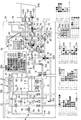
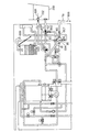
図1に示すように、本発明の第1の実施の形態にかかる浴槽水浄化装置10は、浴槽200に湯を注湯し、この湯を浄化して保温する24時間風呂機能と、台所や浴室などに設けた水栓にお湯を供給する給湯機能とを備えたものである。
【0035】
浴槽水浄化装置10は、浴槽内の水を浄化や追い焚きのために循環させる循環用流路50と、給水を加熱して出湯するための給湯流路30とを有している。給湯流路30および循環用流路50は共にバーナ11の上方に配置された共通の熱交換器12を経由しており、いわゆる一缶二水路型になっている。バーナ11の下方には、燃焼ファン14が配置されている。給排気は、燃焼ファン14によって燃焼室の下方から給気を送風することによって強制的に行われ、排気は燃焼室の上部から排出されるようになっている。
【0036】
バーナ11は、燃焼面Aとこれよりも大きな燃焼面Bとに分割されている。バーナ11の燃焼面Aの近傍には、図示していない点火装置が設けてある。またバーナ11へ供給される燃焼ガスは、ガス電磁弁16、18、元ガス電磁弁17によってオンオフ制御される。このガス電磁弁16、18によって燃焼面Aと燃焼面Bの双方同時、燃焼面Aのみ、燃焼面Bのみの3種類に燃焼面を切り替え得るようになっている。なお、バーナ11に供給する燃焼ガスのガス量は、ガス比例弁19によって調整される。
【0037】
給湯流路30は、熱交換器12のフィンプレートから受熱する配管部分である給湯系受熱管31と、一端が給湯系受熱管31の入側に接続され、他端側が給水の供給元に通じる給水管32と、給湯系受熱管31の出側から延びる給湯管33とから構成されている。給水管32の途中には、通水量を検知するための水量センサ34が設けてある。
【0038】
給湯管33のうち給湯系受熱管31の出側には、給湯流路30を通じて出湯される湯量を調整するための水量制御弁37があり、その下流には、給湯確認用の水量センサ38が取り付けられている。
【0039】
給水管32のうち熱交換器12の入側近傍箇所と給湯管33のうち熱交換器12の出側と水量制御弁37との間の所定箇所との間には、熱交換器12を迂回させて給水管32からの給水を給湯管33に直接流し込むための固定バイパス路40が設けてある。また、給水管32のうち水量センサ34より給水の流入側の所定箇所と給湯管33のうち水量制御弁37と水量センサ38の間の所定箇所との間には、熱交換器12を迂回させて給水管32からの給水を給湯管33に流し込むための可変バイパス路41が設けてある。この可変バイパス路41の途中には、給湯管33に流し込む水量を調整するための水量制御弁42が取り付けてある。
【0040】
循環用流路50は、熱交換器12のフィンプレートから受熱する配管部分である循環系受熱管51と、循環系受熱管51の入側と浴槽200に設けた吸入口201との間を接続する追い焚き戻り管52と、循環系受熱管51の出側と浴槽200に設けた吐出口202との間を接続する追い焚き往き管53とから構成されている。
【0041】
追い焚き往き管53のうち循環系受熱管51の出側近傍の所定箇所54には、可変バイパス路41の合流箇所43と水量センサ38との間で給湯管33から分岐した連絡管44が合流している。連絡管44の途中には、当該連絡管44を閉鎖するか開通させるかを切り替えるための注湯切替弁45が設けてある。注湯切替弁45を開くことで、給湯系受熱管31で加熱された湯が連絡管44を通じて合流箇所54から循環用流路50内へ流れ込み、循環用流路50を通じて浴槽200へ注湯できるようになっている。
【0042】
追い焚き往き管53の途中には、管内の通水を確認するための流水センサ55が設けてある。また追い焚き戻り管52の途中には、第1電動三方弁60と、循環ポンプ70と、電動五方弁80と、第2電動三方弁90と、逆止弁72と、流水センサ73とが吸入口201から熱交換器12の入側に向けて上述の順で配置されている。また流水センサ73には、管内の水温を検知するためのサーミスタ74が組み込まれている。また給湯系受熱管31の入側近傍および出側近傍には、サーミスタ75a、75bが設けてある。
【0043】
第1電動三方弁60は、第1接続口61と、第2接続口62と、第3接続口63とを有している。また電動五方弁80は、第4接続口81から第8接続口85の5つの接続口を有し、第2電動三方弁90は、第9接続口91と、第10接続口92と、第11接続口93とを備えている。追い焚き戻り管52は、浴槽200内の吸入口201から第1電動三方弁60の第1接続口61に入り、第1電動三方弁60の第2接続口62から循環ポンプ70を経由して電動五方弁80の第4接続口81に接続されている。さらに、電動五方弁80の第5接続口82から第2電動三方弁90の第9接続口91へと接続され、第2電動三方弁90の第11接続口93から逆止弁72、流水センサ73を通じて循環系受熱管51の入側に通じている。第1電動三方弁60の第2接続口62から循環ポンプ70に至る途中には、当該部分の配管内の水温を検知するための入側サーミスタ76が取り付けてある。
【0044】
追い焚き往き管53のうち流水センサ55よりもやや吐出口202寄りの箇所には、第3電動三方弁100が設けてある。第3電動三方弁100の第12接続口101には、流水センサ55側からの配管が接続されている。第3電動三方弁100の第13接続口102から延びる配管は追い焚き往き管53の一部を成し、吐出口202へと通じている。また第13接続口102から吐出口202に至る配管の途中から分岐した第1バイパス路121が第1電動三方弁60の第3接続口63に接続されている。第1バイパス路121が分岐する箇所と吐出口202との間の配管には、浴槽200の水位を検出するための圧力センサ56が取り付けてある。
【0045】
第3電動三方弁100の第14接続口103から延びる第2バイパス路122は、吸入口201と第1電動三方弁60の第1接続口61とを結ぶ配管に合流している。また第2電動三方弁90の第2接続口92には、追い焚き往き管53のうち流水センサ55と合流箇所54との間の所定箇所から分岐した第3バイパス路123が接続されている。電動五方弁80の有する第6接続口83はろ過槽110の順方向入側112と接続され、電動五方弁80の第7接続口84には、排水管78が接続されている。電動五方弁80の第8接続口85は、紫外線殺菌灯79を介してろ過槽110の順方向出側111に接続されている。
【0046】
ろ過槽110の内部には、ろ材が格納してあり、順方向入側112から流入した水は、ろ材を通過する際にゴミ等が除去されて浄化され、順方向出側111から排出される。循環ポンプ70は、第1電動三方弁60の第2接続口62側から電動五方弁80の第4接続口81側に向かって管内の水を送り出すようになっている。
【0047】
第1電動三方弁60、第1接続口61と第2接続口62とが連通し第3接続口63の閉鎖される第1第2連通状態と、第2接続口62と第3接続口63とが連通し第1接続口61の閉鎖される第2第3連通状態とに少なくとも電動で切り替え可能になっている。同様に第2電動三方弁90は、第9接続口91と第10接続口92とが連通し第11接続口93の閉そくされる第9第10連通状態と、第9接続口91と第11接続口93とが連通し第10接続口92の閉鎖される第9第11連通状態とに少なくとも電動で切り替え可能になっている。第3電動三方弁100は、第12接続口101と第13接続口102とが連通し第14接続口103の閉鎖される第12第13連通状態と、第12接続口101と第14接続口103とが連通し第13接続口102の閉鎖される第12第14連通状態とに少なくとも電動で切り替え可能になっている。
【0048】
電動五方弁80は、第4接続口81を第5接続口82から第8接続口85のうちのいずれかと連通させるとともに第4接続口81と連通していない残り3つの接続口のうちのいずれか2つの接続口同士の間を連通される連通状態と、いずれの接続口81〜85同士も連通させずに各接続口81〜85を閉鎖する閉鎖状態とに電動で切り替え可能になっている。
【0049】
浴槽水浄化装置10は、給湯動作、注湯動作、追い焚き動作、ろ過運転、機器内熱殺菌処理、喫水面熱殺菌処理、ろ過層の逆洗浄など各種の動作を制御するための制御部250を備えている。制御部250は、CPU(中央処理装置)と、ROM(リード・オンリ・メモリ)とRAM(ランダム・アクセス・メモリ)を主要部とする回路で構成されており、機器内熱殺菌部251と、喫水面熱殺菌部252と、注湯条件取得部253と、関連処理制御部254と、注湯制御部255と、注水制御部256と、逆洗浄制御部257と、追い焚き制御部258としての各機能を果たすようになっている。
【0050】
このうち、機器内熱殺菌部251は、バーナ11の燃焼状態、循環ポンプ70の駆動状態、各弁60、80、90、100の切り替え等を制御して、浴槽水浄化装置10の内部の配管やろ過槽110を熱殺菌する機器内熱殺菌処理を実行するものである。喫水面熱殺菌部252は、機器内熱殺菌部251と同様にバーナ11の燃焼状態、循環ポンプ70の駆動状態、各弁60、80、90、100の切り替え等を制御して、浴槽200の喫水面近傍やプレフィルタ210を熱殺菌する喫水面熱殺菌処理を実行するものである。
【0051】
注湯条件取得部253は、高温の湯を浴槽200に注湯することによって喫水面熱殺菌処理を行う場合に、適切な注湯温度と注湯量とを浴槽200内の水位と水温とに基づいて求める機能を果たす部分である。水位は圧力センサ56によって、浴槽水の水温は入側サーミスタ76によって検知される。
【0052】
注湯制御部255は、バーナ11を燃焼させ、給湯流路30の給湯系受熱管31を通じて水を加熱し、この加熱した水を、注湯切替弁45を開いて、連絡管44、循環用流路50を通じて浴槽200に注湯する動作を制御する部分である。注湯制御部255は、バーナ11を燃焼させないで、給湯流路30からの水を、注湯切替弁45を開いて、連絡管44、循環用流路50を通じて浴槽200に注水する動作を制御する部分である。
【0053】
逆洗浄制御部257は、各弁60、80、90、100および循環ポンプ70を制御して、浴槽水を、ろ過槽110を逆方向(順方向出側111から順方向入側112へ)に通過させた後、排水管78から排水する逆洗浄処理を行う部分である。関連処理制御部254は、喫水面熱殺菌処理に関連した逆洗浄処理や注水処理などの実行を制御する機能を果たす部分である。追い焚き制御部258は、浴槽水を取り込み、循環用流路50を通じて加熱し、これを再び浴槽内に戻すように循環させて、浴槽水を追い焚きする機能を果たすものである。追い焚き制御部258は、喫水面熱殺菌処理を実行する際には、吸入口201から湯を吐出するようになっている。
【0054】
制御部250には、各種の弁60、80、90、100やガス電磁弁16〜19のほか、循環ポンプ70、流水センサ55、73、圧力センサ56、各種サーミスタ74、75a、75b、76など各種の制御部品やセンサ類が簡略図示した配線259によって電気的に接続されている。また制御部250には、出湯温度の設定や、風呂の追い焚き指示等を受け付けるためのリモコン260が接続されている。リモコン260は浴室、台所等に設置されるものである。
【0055】
リモコン260は、風呂の設定温度等を変更するための各種スイッチから成る操作部261と、現時点での設定温度や各種の動作状態などを表示するための表示部262と、各種予約動作の開始時刻、終了時刻を管理するタイマ部263とを有している。
【0056】
次に作用を説明する。
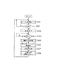
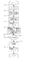
図2は、浴槽水浄化装置10が行う一連の動作の流れを示している。たとえば、一日のうち午後4時から午後11までの間、入浴可能な状態を維持するように予約されている場合には、この時間帯については、通常のろ過運転が行われる(ステップS301)。ろ過運転は、浴槽200内の水をろ過槽110を経由するように循環用流路50を循環させて浄化する運転モードである。
【0057】
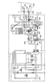
図3に示すように、ろ過運転では、第1電動三方弁60は、第1接続口61と第2接続口62とが連通し、第3接続口63の閉塞された第1第2連通状態に設定される。また電動五方弁80は、第4接続口81と第6接続口83が連通し、かつ第8接続口85と第5接続口82の連通する状態に設定される。
【0058】
さらに第2電動三方弁90は、循環中の浴槽水を加熱しながら浄化する場合には、第9接続口91と第11接続口93とが連通する状態(熱交換器12を経由する状態)に設定され、保温すべき設定温度に達し、さらに加熱する必要のない場合は、第9接続口91と第10接続口92とが連通する状態(熱交換器12を迂回する状態)に設定される。第3電動三方弁100は、第12接続口101と第13接続口102とが連通する状態に設定される。
【0059】
したがって、熱交換器12で加熱する場合は、図中の矢印381〜391で示す経路で浴槽水が循環する。非加熱の場合は、上記の経路のままでも良いが、給湯動作が開始されると、給湯系受熱管31とともに循環系受熱管51も同時に加熱され、浴槽水を設定保温温度に維持することができなくなったり、給湯動作がないときに熱交換器12での放熱により水温が低下するので、これらを避けるために第2電動三方弁90を第9接続口91と第10接続口92とが連通する状態に設定し、図中の矢印395、396で示す経路で熱交換器12を迂回するようになっている。
【0060】
上述のような経路で浴槽水を循環させてろ過槽110で浄化するろ過運転の終了時刻が到来すると(ステップS302;Y)、浴槽水の保温動作を終了する(ステップS303)。すなわち、以後は、浴槽水を循環させてろ過槽110で浄化するが、保温は行わなくなる。その後、次の保温動作の開始予定時刻(ここでは次の日の午後4時)の30分前までは、保温動作の休止した状態が継続され、開始予定時刻の30分前になると(ステップS304;Y)、まず機器内熱殺菌処理が開始される(ステップS305)。
【0061】
図4は、機器内熱殺菌処理時に循環ポンプから送り出される水の流れる経路を示している。機器内熱殺菌処理時において、電動五方弁80は、ろ過運転の場合と同じ状態に設定される。第1電動三方弁60は第3接続口63と第2接続口62とが連通する状態に設定され、第2電動三方弁90は、第9接続口91と第11接続口93とが連通する状態に設定される。さらに第3電動三方弁100は、第12接続口101と第13接続口102とが連通する状態に設定される。
【0062】
この状態で循環ポンプ70を駆動すると、当該循環ポンプ70によって送り出された水は、矢印401〜413で示すような経路を循環する。機器内熱殺菌処理は、バーナー11を適宜燃焼させることによって、環状経路401〜413内の水を約65℃に加熱した状態で維持しつつ、数分間、この環状経路内で湯を循環させるものである。
【0063】
機器内熱殺菌処理が終了すると、次に喫水面熱殺菌処理が行われる(図3、ステップS306)。図5は、浴槽水を追い焚きする場合における喫水面熱殺菌処理の流れを示している。まず循環ポンプ70を停止し(ステップS501)、各弁60、80、90、100を切り換えて喫水面殺菌経路を形成する。
【0064】
図1に示すように、喫水面殺菌経路では、第1電動三方弁60は第3接続口63と第2接続口62とが連通する状態に設定される。電動五方弁80は、第4接続口81と第5接続口82とが連通する状態に設定される。第2電動三方弁90は、第9接続口91と第11接続口93とが連通する状態に、第3電動三方弁100は、第12接続口101と第14接続口103とが連通する状態に設定される。
【0065】
喫水面殺菌経路を形成した後、循環ポンプ70を最小能力でオンにする(ステップS503)。これにより、図1の矢印521〜536で示すような経路で浴槽水が循環し追い焚きが行われる。すなわち、吐出口202から浴槽水が取り込まれ(矢印521、522)、この浴槽水は第1電動三方弁60を第3接続口63から第2接続口62へと通過し(矢印525)、循環ポンプ70を経由し(矢印526、527)、電動五方弁80を第4接続口81から第5接続口82へと通過する(矢印528)。その後、第2電動三方弁90を第9接続口91から第11接続口93へと通過し(矢印529)、熱交換器12で加熱され(矢印530、531、532、533)、さらに第3電動三方弁100を第12接続口101から第14接続口103へ通過して(矢印534)、吸入口201から浴槽内に流れ出る(矢印535、536)。
【0066】
こうして喫水面熱殺菌処理としての追い焚きが始まると熱殺菌タイマをスタートさせ(ステップS505)、当該タイマが15分を計時するまで、最小能力で循環ポンプ70を駆動する(ステップS506)。喫水面熱殺菌処理中は、吸入口201から約65℃以上(70℃くらい)の湯がゆっくりと流れ出る。15分が経過した後、循環ポンプ70を停止し(ステップS507)、各弁60、80、90、100を切り換えて(ステップS508)、図3に示すろ過運転用の経路を設定し、熱殺菌タイマをリセットする(ステップS509)。
【0067】
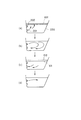
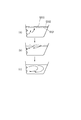
喫水面熱殺菌中は、吸入口201からゆっくりと高温の湯が吐出するので、図6aに示すように、浴槽200内での攪拌がほとんど起こらず、吸入口201から吐出した湯は、ゆっくりと上昇し、喫水面近傍に高温の湯(約65℃)からなる高温層601を形成する。
【0068】
図7は、喫水面熱殺菌処理の前後における喫水面近傍の水温と吸入口201に取り付けたプレフィルタ210の温度変化を示している。時刻t1から循環ポンプ70を最小能力で駆動して喫水面熱殺菌処理が始まると、破線701で示すように、プレフィルタ210の温度がまもなく上昇する。実線702で示した喫水面近傍の水温は、吸入口201から水面まで湯が上昇する間に、まわりの浴槽水によってある程度冷却されるので、プレフィルタ210に比べて緩やかに温度上昇する。そして時間の経過とともに喫水面近傍の水温702もほぼ60℃を越える温度まで上昇する。
【0069】
時刻t2に喫水面熱殺菌処理が終了すると、ろ過運転の状態に経路を切り替えて循環ポンプ70を通常の能力(大能力)で駆動する。これにより、図6bに示すように浴槽水が浴槽200内で攪拌され、図7に示すように喫水面近傍の水温およびプレフィルタ210の温度が浴槽水の平均温度710まで下降する(時刻t3)。このとき、攪拌後の浴槽水の平均水温710は、喫水面熱殺菌処理を行う前の水温710よりも、喫水面熱殺菌のために追い焚きを行った分だけ上昇することになる。
【0070】
喫水面熱殺菌処理が終了した後、ろ材の逆洗浄処理を行う(図2、ステップS306)。逆洗浄では、図8に示すように経路が設定される。この状態で循環ポンプ70を駆動することで、矢印801〜808で示すように、吸入口201から浴槽水が取り込まれ、これがろ過槽110を逆方向に流れ、排水管78から排出される。したがって、図6cに示すように破線で示した元の水位610に比べて、水位が実線611で示す所まで低下する。
【0071】
このように逆洗浄を行うと、元の水位610から水位が低下するので、喫水面熱殺菌処理を逆洗浄の前に行うようにしている。すなわち、雑菌繁殖の温床となるゴミは、元の喫水面の近傍に存在するので、逆洗浄の前に熱殺菌することで、元の水位における喫水面近傍が熱殺菌される。
【0072】
逆洗浄すると、水位が低下するので、その後、図6dに示すように注湯や注水あるいは通常の追い焚き動作を行うことで、浴槽水を設定温度かつ設定水位とし(ステップS308)、予約されたろ過運転開始時刻(保温開始時刻…ここでは午後4時)が到来するまでには、入浴の可能な状態となって、ろ過運転に移行する(ステップS301)。図7のグラフでは、逆洗浄等を時刻t3からt4までの間に行っている。また平均水温が設定温度より高いので、時刻t4から注水を行って水温を設定温度まで下降させている。
【0073】
なお図7のグラフでは、喫水面熱殺菌処理の開始前に既に浴槽水温が40℃であったが、通常は、熱殺菌処理を開始する前の数時間にわたって保温動作を停止しているので、浴槽水温はもっと低い温度になっている。したがって、保温開始時刻にちょうど入浴可能な状態になるように機器内熱殺菌処理や喫水面熱殺菌処理を保温開始時刻の所定時間前に行うことで、熱殺菌のために行った加熱が、保温動作の開始に備えて浴槽水温を高めるための加熱を兼ねることとなり、エネルギー節約に貢献する。
【0074】
次に、第2の実施の形態について説明する。
第1の実施の形態では、喫水面熱殺菌処理のあとに、浴槽水の攪拌を行ってから逆洗浄を行ったが、第2の実施の形態では喫水面近傍に存する高温の水を積極的に利用してろ材の逆洗浄を行うようになっている。
【0075】
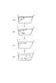
第2の実施の形態では、図9aに示すように、第1の実施の形態と同様に機器内熱殺菌処理が行われ、これに続いて喫水面熱殺菌処理が行われる。その後、同図bに示すように吐出口202から浴槽水を取り込んで逆洗浄を行う。図10は、吐出口202から浴槽水を取り込む場合における逆洗浄時の通水経路を示している。第3電動三方弁100は、第13接続口102が閉鎖された状態に設定され、第1電動三方弁60は、第3接続口63と第2接続口62とが連通した状態に設定される。電動五方弁80は、第4接続口81と第8接続口85が連通しかつ第6接続口83と第7接続口84とが連通する状態に設定される。これにより循環ポンプ70を駆動することで矢印1001〜1008で示すように浴槽水が流れる。
【0076】
このように喫水面熱殺菌処理の後、攪拌することなくすぐに逆洗浄を開始するとともに、その際、浴槽水を喫水面近くの吐出口202から取り込むので、喫水面近傍に存する高温層から高温の湯を効率良く取り込んでろ過槽110等を逆洗浄することができる。
【0077】
逆洗浄後は、水位が低下するので、図9cに示すように注湯あるいは注水によって水位を元の状態に戻し、さらに設定温度にするために追い焚き等が行われる(図9d)。
【0078】
次に、第3の実施の形態について説明する。
第1、第2の実施の形態では、浴槽水を追い焚きすることによって喫水面の熱殺菌を行ったが、第3の実施の形態では、新たな湯を注湯することで喫水面の熱殺菌処理を行うようになっている。
【0079】
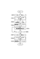
図11は、第3の実施の形態にかかる浴槽水浄化装置10が行う喫水面熱殺菌処理の流れを示している。この処理は、第1、第2の実施の形態の場合と同様に、図3の流れ図におけるステップS306にて実行される。先ず循環ポンプ70を停止し(ステップS1101)、現時点での浴槽水の水温と水位とを検知する(ステップS1102)。検知した水温と水位とに基づいて、注湯条件取得部253は、注湯温度および注湯量を決定する(ステップS1103)。
【0080】
注湯条件取得部253は、圧力センサ56によって検知された浴槽200内の水位と入側サーミスタ76によって検知された浴槽200内の水温とから、浴槽200内の水面近傍に目標温度(たとえば65℃)の高温層を形成するために、何度の湯をどれだけ注湯すべきかを求める。吸入口201からゆっくり吐出された湯は、喫水面近傍まで上昇する間に、まわりの浴槽水の影響である程度冷却される。また吸入口201から喫水面までの距離(すなわち水位)によってもどの程度温度が下がるかが変動する。そこで、浴槽水の温度や水位に応じて注湯温度が設定される。また、注湯によって湯が浴槽200から溢れることがないように、総注湯量が設定される。
【0081】
次に、喫水面熱殺菌部252は、熱殺菌タイマをスタートさせ(ステップS1104)、注湯条件取得部253が求めた温度の湯を注湯条件取得部253が求めた湯量だけ、吸入口201から浴槽200に15分間かけて注湯する(ステップS1105、ステップS1106)。また水量制御弁37やバーナ11の燃焼量を制御して、この際の注湯速度を、浴槽200内での撹拌が少なく抑えられるように遅く設定し、浴槽内の水面付近に高温層を形成して喫水面近傍の熱殺菌を行う。その後、注湯動作を停止し(ステップS1107)、熱殺菌タイマをリセットする(ステップS1108)。
【0082】
このように、浴槽水の水温と水位を調べ、これらに基づいて注湯温度と注湯量を求めるので、喫水面近傍に目標温度の高温層を確実に形成することができ、的確に熱殺菌を行うことができる。
【0083】
図12は、注湯によって喫水面熱殺菌処理を行う場合の水位の変動等を示している。喫水面熱殺菌処理に基づく注湯動作を開始する前の水位(破線1201)に比べて、喫水面熱殺菌処理実行後は、水位が実線1202で示す所まで上昇している。このように注湯によって水位が上昇する場合でも、喫水面近傍に形成される高温層1203の下端が、元の水位と同じか、わずかに低いところに来るようにすれば、元の水位における浴槽壁面部分を熱殺菌することができる。
【0084】
さらに、通常、人が入浴すると水位が上昇するので、元の喫水面1201よりも高い箇所の浴槽壁面に湯垢が付着していることが考えられる。そこで、注湯によって人が入浴している分に相当するだけ注湯より水位を高めれば、先の高い箇所の浴槽壁面に付着した湯垢等も熱殺菌することができる。
【0085】
喫水面熱殺菌処理を実行した後は、吐出口202から喫水面近傍の高温層の湯を取り込んで逆洗浄等を行い、水位を戻す(図12b)。その後、浴槽水の温度が設定温度になるように追い焚き等をさらに行う(図12c)。
【0086】
なお、喫水面熱殺菌処理の前に水位を調べた結果、その水位が既に高く、十分な量を注湯ができない場合には、喫水面熱殺菌処理に先立ってある程度の水量を浴槽200から排水管78を通じて排水してもよい。
【0087】
このほか、水位や水温に基づいて注湯温度や注湯湯量を注湯条件取得部253で毎回算出したが、浴槽水の水位や水温にかかわらず、予め定めた一定温度の湯を予め定めた一定量だけ注湯するようにしてもよい。この場合には、喫水面熱殺菌処理による注湯後に、圧力センサ56で水位を測定し、必要な量だけ逆洗浄しつつ排水して水位を調整したり、喫水面熱殺菌処理後に入側サーミスタ76で測定した浴槽水の水温に基づき、浴槽水の平均温度が設定温度になるように追い焚きや注水を行うことになる。また浴槽水の水温等を調べずに一定温度の湯を注湯する場合には、浴槽水が十分に冷えている場合や水位が高い悪条件時を想定し、余裕を持って予め注湯温度を高めに設定したり等することが望ましい。
【0088】
以上説明した実施の形態では、プレフィルタ210も同時に熱殺菌できるように喫水面熱殺菌処理時に吸入口201から湯を吐出するようにしたが、プレフィルタ210の熱殺菌を考慮しなければ、通常どおり吐出口202から、あるいは吸入口201と吐出口202の両方から高温水を吐出してもよい。また第1、第2の実施の形態では、喫水面熱殺菌処理時に循環ポンプ70を最小能力でオンにして追い焚きを行ったが、攪拌が少なく抑えられ喫水面に高温層ができるようにゆっくり吐出できれば、最小能力に限定されるものではない。また、循環ポンプ70を全くオフにした状態で自然循環による追い焚きが可能であれば、これでもよい。また循環ポンプ70のオンオフを繰り返す間欠運転を行うことで、平均の吐出速度を下げるようにしてもよい。
【0089】
このほか、実施の形態では、喫水面熱殺菌処理の当初からゆっくりと高温水を吐出するようにしたが、喫水面熱殺菌処理の当初は、勢い良く吐出して浴槽水を攪拌して全体的に湯温を上昇させ、その後、ゆっくり吐出するように変更し、少なくとも喫水面熱殺菌処理の終了段階で水面付近に高温層が形成されるようにしてもよい。このようにすれば、喫水面近傍にたまる高温水の温度をより適切に判断することができる。すなわち、浴槽水温度が平均化されることと浴槽水温度が平均的に上昇するので、吐出後、喫水面に至るまでの温度低下がどのように起こるかを的確に予測でき、喫水面の近傍に目標温度の高温層を形成することができる。
【0090】
また各実施の形態では、予約された保温動作の開始時刻に入浴可能な状態になるように、保温開始時刻の数十分前から各熱殺菌処理を開始するようにしたが、24時間、常に保温動作を行う場合や、タイマ予約の機能がない場合には、適宜のタイミングで喫水面熱殺菌処理を行えばよい。たとえば、毎日、夜中の3時に機器内熱殺菌処理と、喫水面熱殺菌処理と、逆洗浄とをこの順で行う等である。
【0091】
このほか、浴槽水を追い焚きする喫水面熱殺菌処理と注湯する喫水面熱殺菌処理とを組み合わせてもよい。すなわち、当初は、追い焚き形式で喫水面熱殺菌処理を行い、元の水位近傍を熱殺菌し、次いで、注湯形式で喫水面熱殺菌処理を行い、元の水位よりも高い箇所の浴槽壁面を熱殺菌するように構成してもよい。
【0092】
また喫水面熱殺菌処理の際にプレフィルタ210のある吸入口201側から高温水を吐出するものでは、プレフィルタに付着しているゴミ等が浴槽内に散乱しないように、吐出速度を極力低下させたり、喫水面熱殺菌処理の後でしばらくろ過運転を行って保温開始時刻が来る前に浴槽水のゴミをプレフィルタ210等で除去するようにすると良い。
【0093】
なお、実施の形態では、水位検知手段として圧力センサ56を用いたが、浴槽水の水位を他の方法によって検知してもよい。たとえば、一定量の注湯や、一定時間等の追い焚き等によって外部からの熱量を与えて、その後、循環ポンプを駆動して浴槽湯温を検出し、水温の上昇幅と与えた熱量等とから浴槽内の水量(水位)を求めるようにしてもよい。
【0094】
【発明の効果】
本発明にかかる浴槽水浄化装置によれば、浴槽に設けた吐出口から高温の水を浴槽内での撹拌が少なく抑えられるようにゆっくりと吐出するので、浴槽内の水面付近に高温の湯の層が形成され、喫水面近傍を効率良く熱殺菌することができる。
【0095】
また、注湯によって喫水面の熱殺菌を行う場合、当該処理に先立って浴槽水の水温と水位を調べ、これらに基づいて喫水面熱殺菌処理での注湯温度と注湯量を求めるので、喫水面近傍に目標温度の高温層を確実に形成することができ、的確な熱殺菌を行うことができる。
【0096】
また、喫水面熱殺菌処理の前後において排水や注水あるいは注湯を行うことで浴槽水の水位や水温を調整するので、喫水面熱殺菌処理の前後の状態を一致させたり、入浴可能な状態にすることができる。
【0097】
また、追い焚きによる喫水面熱殺菌処理後に、浴槽水でろ過槽の逆洗浄を行うものでは、逆洗浄を先に行う場合のように、喫水面熱殺菌処理時に水位が低下していないので、元の水位の喫水面近傍を的確に熱殺菌することができる。さらに高温層が形成されている喫水面にできるだけ近い出入口から浴槽水を取り込むものでは、高温水をろ過層の逆洗浄およびその殺菌に有効利用することができる。
【0098】
また浴槽内の水を入浴可能な状態にすべき保温開始時刻が予約されているとき、この保温開始時刻に、喫水面の殺菌を含む一連の処理が終了して入浴可能な状態になるように、予約された保温開始時刻から逆算した時刻から喫水面の殺菌動作等を開始するので、喫水面を熱殺菌するための加熱で保温開始時に浴槽水を設定温度に高めるための加熱を兼ねることができ、省エネルギ化に貢献することができる。
【0099】
さらに通常のろ過運転時に浴槽水を吸い込む吸入口を、喫水面の殺菌時に高温の水を吐出する吐出口として用いることで、吸入口の側に取り付けられているフィルタの熱殺菌を喫水面の熱殺菌と同時に行うことができる。
【図面の簡単な説明】
【図1】本発明の各実施の形態に係る浴槽水浄化装置の構成を示す説明図である。
【図2】本発明の各実施の形態に係る浴槽水浄化装置が行う動作の流れを示す流れ図である。
【図3】本発明の各実施の形態に係る浴槽水浄化装置がろ過運転を行う際の通水経路を示す説明図である。
【図4】本発明の各実施の形態に係る浴槽水浄化装置が機器内熱殺菌処理を行う際の通水経路を示す説明図である。
【図5】本発明の第1の実施の形態に係る浴槽水浄化装置の行う喫水面熱殺菌処理を示す流れ図である。
【図6】本発明の第1の実施の形態に係る浴槽水浄化装置が喫水面熱殺菌処理およびその後の関連処理を行う際の水位の変化を示す説明図である。
【図7】本発明の第1の実施の形態に係る浴槽水浄化装置が喫水面熱殺菌処理およびその関連処理を行う際における喫水面近傍およびプレフィルタ近傍の水温の変化を示す説明図である。
【図8】吸入口から浴槽水を取り込んでろ過槽等の逆洗浄を行う際の通水経路を示す説明図である。
【図9】本発明の第2の実施の形態に係る浴槽水浄化装置が喫水面熱殺菌処理およびその後の関連処理を行う際の水位の変化を示す説明図である。
【図10】吐出口から浴槽水を取り込んでろ過槽等の逆洗浄を行う際の通水経路を示す説明図である。
【図11】本発明の第3の実施の形態に係る浴槽水浄化装置の行う喫水面熱殺菌処理を示す流れ図である。
【図12】本発明の第3の実施の形態に係る浴槽水浄化装置が喫水面熱殺菌処理およびその後の関連処理を行う際の水位の変化を示す説明図である。
【符号の説明】
10…浴槽水浄化装置
11…バーナ
12…熱交換器
14…燃焼ファン
30…給湯流路
31…給湯系受熱管
32…給水管
33…給湯管
34、38…水量センサ
37、42…水量制御弁
40…固定バイパス路
41…可変バイパス路
44…連絡管
45…注湯切替弁
50…循環用流路
51…循環系受熱管
52…追い焚き戻り管
53…追い焚き往き管
55、73…流水センサ
56…圧力センサ
60…第1電動三方弁
61〜63…第1、第2、第3接続口
70…循環ポンプ
72…逆止弁
76…入側サーミスタ
78…排水管
80…電動五方弁
81〜85…第4、第5、第6、第7、第8接続口
90…第2電動三方弁
91〜93…第9、第10、第11接続口
100…第3電動三方弁
101〜103…第12、第13、第14接続口
110…ろ過槽
111…順方向出側
112…順方向入側
121…第1バイパス路
122…第2バイパス路
123…第3バイパス路
200…浴槽
201…吸入口
202…吐出口
210…プレフィルタ[0001]
BACKGROUND OF THE INVENTION
The present invention relates to a bathtub water purification apparatus that circulates and purifies water in a bathtub through a filtration tank.
[0002]
[Prior art]
Conventionally, various 24-hour bathing apparatuses have been proposed in which a filtration tank is incorporated in the middle of a circulation channel for circulating bathtub water so that the water in the bathtub can be used for a long period of time without being discarded. In such an apparatus, hot water heated to a high temperature of about 65 ° C. by a heater or the like is passed through the filtration tank or the like to be sterilized by heat in order to kill germs or the like that propagate in the filtration tank or the circulation channel. ing.
[0003]
For example, by providing a bypass passage and a switching valve in the middle of the circulation channel, a small annular path including a filtration tank and bypassing the bathtub can be formed, and a part of the bathtub water is circulated in the annular path. Heat sterilization is carried out by boiling.
[0004]
[Problems to be solved by the invention]
If the water in the bathtub is ideally circulated during the filtration operation, dirt does not adhere to the wall surface of the bathtub, but dirt remains on the draft surface and tends to adhere. The dirt adhering to the bathtub wall in the vicinity of the draft surface becomes a hotbed of various bacteria, and as a result, the bacteria propagate in the bathtub.
[0005]
However, in the conventionally used 24-hour bathing apparatus, since hot sterilization is performed by circulating hot water in a small annular path including the filtration tank, the bathtub wall surface near the draft surface was not thermally sterilized. . In addition, a pre-filter for removing dust is provided at the portion that serves as an inlet for bathtub water during the filtration operation. However, in the conventional apparatus, the pre-filter portion was not thermally sterilized.
[0006]
In this way, in order to thermally sterilize the vicinity of the draft surface and the pre-filter, the method of raising the temperature of the entire bath water to a temperature capable of thermal sterilization (about 65 ° C.) consumes a great deal of energy. Since there are problems such as deformation and excessive bathing, there is a problem such as burns, so it is not realistic and no suitable heat sterilization method has been found.
[0007]
The present invention has been made by paying attention to such problems of the conventional technology, and provides a bathtub water purification device capable of efficiently thermally sterilizing a pre-filter attached to the vicinity of a draft surface or a suction port. The purpose is that.
[0008]
[Means for Solving the Problems]
The gist of the present invention for achieving the object lies in the inventions of the following items.
[1] In a bathtub water purification device (10) that circulates and purifies water in a bathtub (200) through a filtration tank (110),
A draft surface sterilization means (252) for performing a draft surface thermal sterilization treatment for thermally sterilizing the vicinity of the draft surface of the bathtub (200);
The draft surface sterilization means (252) discharges high-temperature water from a discharge port (201) provided in the bathtub (200), and in the bathtub (200) at least at the end stage of the draft surface heat sterilization process. The bathtub water purification device (10) is characterized in that a high-temperature layer is formed in the vicinity of the water surface in the bathtub (200) by slowly discharging high-temperature water so that the agitation of the water is reduced.
[0009]
[2] In the bathtub water purification device (10) for circulating and purifying the water in the bathtub (200) through the filtration tank (110),
A water level detection means (56) for detecting the water level in the bathtub (200), a temperature sensor (76) for detecting the water temperature in the bathtub (200), and a discharge port (201) provided in the bathtub (200) A pouring means (255, etc.) for pouring hot water, and a pouring condition acquisition means (253) for determining the temperature and amount of hot water to be poured into the bathtub (200) by the pouring means (255, etc.) A draft surface sterilization means (252) for performing a draft surface thermal sterilization process for thermally sterilizing the vicinity of the draft surface of the bathtub (200),
The pouring condition acquisition means (253) includes a water level in the bathtub (200) detected by the water level detection means (56) and a water temperature in the bathtub (200) detected by the temperature sensor (76). The temperature and amount of hot water to be poured into the bathtub (200) in order to form a high-temperature layer made of water of a target temperature in the vicinity of the water surface in the bathtub (200),
The draft surface sterilizing means (252) uses the hot water pouring means (255, etc.) by the amount of hot water determined by the pouring condition acquisition means (253) for the hot water determined by the pouring condition acquisition means (253). Controlled and poured into the bathtub (200), and the pouring speed at that time is set to be slow so that stirring in the bathtub (200) is suppressed at least at the end of the draft surface heat sterilization treatment. Thus, the bathtub water purification device (10) is characterized in that a high temperature layer is formed in the vicinity of the water surface in the bathtub (200).
[0010]
[3] In the bathtub water purification device (10) for circulating and purifying the water in the bathtub (200) through the filtration tank (110),
A water level detection means (56) for detecting the water level in the bathtub (200), a temperature sensor (76) for detecting the water temperature in the bathtub (200), and a discharge port (201) provided in the bathtub (200) A pouring means (255, etc.) for pouring hot water, and a pouring condition acquisition means (253) for determining the temperature and amount of hot water to be poured into the bathtub (200) by the pouring means (255, etc.) A draft surface sterilization means (252) for performing a draft surface thermal sterilization process for thermally sterilizing the vicinity of the draft surface of the bathtub (200), and a related treatment means (254),
The pouring condition acquisition means (253) includes a water level in the bathtub (200) detected by the water level detection means (56) and a water temperature in the bathtub (200) detected by the temperature sensor (76). The temperature and amount of hot water to be poured into the bathtub (200) in order to form a high-temperature layer made of water of a target temperature in the vicinity of the water surface in the bathtub (200),
The draft surface sterilizing means (252) uses the hot water pouring means (255, etc.) by the amount of hot water determined by the pouring condition acquisition means (253) for the hot water determined by the pouring condition acquisition means (253). Controlled and poured into the bathtub (200), and the pouring speed at that time is set to be slow so that stirring in the bathtub (200) is suppressed at least at the end of the draft surface heat sterilization treatment. To form a high temperature layer near the water surface in the bathtub (200),
The related processing means (254) has drainage means (255, 78) for draining the water in the bathtub (200), and drains the bathtub water to adjust the amount of water. (10).
[0011]
[4] In the bathtub water purification device (10) for circulating and purifying water in the bathtub (200) through the filtration tank (110),
A water level detection means (56) for detecting the water level in the bathtub (200), a temperature sensor (76) for detecting the water temperature in the bathtub (200), and a discharge port (201) provided in the bathtub (200) A pouring means (255, etc.) for pouring hot water, and a pouring condition acquisition means (253) for determining the temperature and amount of hot water to be poured into the bathtub (200) by the pouring means (255, etc.) A draft surface sterilizing means (252) for executing a draft surface thermal sterilization process for thermally sterilizing the vicinity of the draft surface of the bathtub (200), and a related processing means (254),
The pouring condition acquisition means (253) includes a water level in the bathtub (200) detected by the water level detection means (56) and a water temperature in the bathtub (200) detected by the temperature sensor (76). The temperature and amount of hot water to be poured into the bathtub (200) in order to form a high-temperature layer made of water of a target temperature in the vicinity of the water surface in the bathtub (200),
The draft surface sterilizing means (252) uses the hot water pouring means (255, etc.) by the amount of hot water determined by the pouring condition acquisition means (253) for the hot water determined by the pouring condition acquisition means (253). Controlled and poured into the bathtub (200), and the pouring speed at that time is set to be slow so that stirring in the bathtub (200) is suppressed at least at the end of the draft surface heat sterilization treatment. To form a high temperature layer near the water surface in the bathtub (200),
The related processing means (254) includes drainage means (255, 78) for draining water in the bathtub (200) and water injection means (256, 44, 45) for pouring water into the bathtub (200). And
The related processing means (254) adjusts the amount of water by draining the bathtub water by the draining means (255, 78), and also performs an average water temperature in the bathtub (200) by performing the draft surface heat sterilization treatment. When the temperature becomes higher than a preset temperature, water is injected into the bathtub (200) by the water injection means (256, 44, 45) after the draft surface heat sterilization treatment, and the bathtub ( 200) The bathtub water purification apparatus (10) characterized in that when it is necessary to adjust the amount of water in the water, the water is drained by the drainage means (255, 78) after at least the draft surface heat sterilization treatment.
[0012]
[5] In the bathtub water purification device (10) for purifying the water in the bathtub (200) by circulating it through the filtration tank (110),
A water level detection means (56) for detecting the water level in the bathtub (200), a temperature sensor (76) for detecting the water temperature in the bathtub (200), and a discharge port (201) provided in the bathtub (200) Hot water pouring means (255, etc.) for pouring hot water, draft surface sterilization means (252) for executing draft surface thermal sterilization treatment for thermally sterilizing the vicinity of the draft surface of the bathtub (200), and related processing means (254) With
The draft surface sterilizing means (252) controls the pouring means (255, etc.) by pouring a predetermined amount of hot water into the bathtub (200) and pouring hot water at a predetermined temperature. Forming a high temperature layer in the vicinity of the water surface in the bathtub (200) by setting the hot water speed slow so that stirring in the bathtub (200) is suppressed at least at the end of the draft surface heat sterilization treatment And
The related processing means (254) has drainage means (255, 78) for draining the water in the bathtub (200), and adjusts the amount of water by draining the bathtub water. Device (10).
[0013]
[6] In the bathtub water purification device (10) for purifying the water in the bathtub (200) by circulating it through the filtration tank (110),
A water level detection means (56) for detecting the water level in the bathtub (200), a temperature sensor (76) for detecting the water temperature in the bathtub (200), and a discharge port (201) provided in the bathtub (200) Hot water pouring means (255, etc.) for pouring hot water, draft surface sterilization means (252) for executing draft surface thermal sterilization treatment for thermally sterilizing the vicinity of the draft surface of the bathtub (200), and related processing means (254) With
The draft surface sterilizing means (252) controls the pouring means (255, etc.) by pouring a predetermined amount of hot water into the bathtub (200) and pouring hot water at a predetermined temperature. Forming a high temperature layer in the vicinity of the water surface in the bathtub (200) by setting the hot water speed slow so that stirring in the bathtub (200) is suppressed at least at the end of the draft surface heat sterilization treatment And
The related processing means (254) includes drainage means (255, 78) for draining water in the bathtub (200) and water injection means (256, 44, 45) for pouring water into the bathtub (200). And
The related processing means (254) adjusts the amount of water by draining the bathtub water by the draining means (255, 78), and also performs an average water temperature in the bathtub (200) by performing the draft surface heat sterilization treatment. When the temperature becomes higher than a preset temperature, water is injected into the bathtub (200) by the water injection means (256, 44, 45) after the draft surface heat sterilization treatment, and the bathtub ( 200) The bathtub water purification apparatus (10) characterized in that when it is necessary to adjust the amount of water in the water, the water is drained by the drainage means (255, 78) after at least the draft surface heat sterilization treatment.
[0014]
[7] The drainage means (255, 78) drains bathtub water after the draft surface heat sterilization treatment is completed, and reverses the bathtub water to the filtration tank (110) during normal filtration operation. The bath water purifier (10) according to [3], [4], [5] or [6], wherein the water is drained after passing through the water.
[0015]
[8] In the bathtub water purification device (10) for circulating and purifying water in the bathtub (200) through the filtration tank (110),
Reheating means for replenishing the bathtub water by taking in the bathtub water from the suction port provided in the bathtub (200), heating it with a predetermined heating means, and discharging it from the discharge port (201) provided in the bathtub (200). 258), draft surface sterilization means (252) for performing draft surface thermal sterilization treatment for thermally sterilizing the vicinity of the draft surface of the bathtub (200), and related treatment means (254),
The draft surface sterilization means (252) controls the reheating means (258) to discharge high-temperature water from the discharge port (201), and at least at the end stage of the draft surface heat sterilization process, the bathtub ( 200) to form a high-temperature layer in the vicinity of the water surface in the bathtub (200) by slowly discharging high-temperature water so that stirring in the interior is suppressed to a low level,
The related processing means (254) has drainage means (255, 78) for draining water in the bathtub (200),
The drain means (255, 78), when the draft surface heat sterilization by the draft surface sterilization means (252) is finished, drains a predetermined amount of bath water after passing through the filtration tank (110). Bath water purification device (10).
[0016]
[9] When there are two or more entrances leading to the filtration tank (110) at different positions of the bathtub (200), the drainage means (255, 78) is arranged so that the bath water from the entrance located above them The bathtub water purification device (10) according to [7] or [8], wherein the water is taken out after passing through the filtration tank (110).
[0017]
[10] When a heat retention start time that should allow the water in the bathtub (200) to be bathed is reserved, a series of processes including sterilization of the draft surface is completed at the heat retention start time, and the bathing is performed. [1], [2], [3], [4], [4], [3], [3], [4], [4], [3], wherein the draft surface heat sterilization process is started from a time obtained by calculating backward from the heat retention start time. Bath water purification apparatus (10) according to [5], [6], [7], [8] or [9].
[0018]
[11] A filter attached to the side of the suction port by using a suction port for sucking in the bathtub water during normal filtration operation as a discharge port (201) for discharging high-temperature water when the draft surface heat sterilization process is performed. [1], [2], [3], [4], [5], [6], [7], [8], wherein the heat sterilization of [9] The bathtub water purification device (10) according to [10].
[0019]
The present invention operates as follows.
The draft surface sterilization means (252) can suppress the stirring of the hot water from the discharge port (201) provided in the bathtub (200) in the bathtub (200) at least at the end of the draft surface thermal sterilization process. Slowly dispense. Thereby, a hot water layer is formed near the water surface in the bathtub (200), and the vicinity of the draft surface can be efficiently heat sterilized.
[0020]
The hot water may be discharged slowly from the beginning of the draft surface heat sterilization treatment, or initially, the hot water may be discharged vigorously to agitate the bath water to raise the overall hot water temperature, and then slowly discharged. In this case, a high temperature layer may be formed near the water surface in the final stage.
[0021]
Further, the pouring condition acquisition means (253) calculates the bathtub (from the water level in the bathtub (200) detected by the water level detection means (56) and the water temperature in the bathtub (200) detected by the temperature sensor (76). 200), in order to form a high-temperature layer composed of water having a target temperature in the vicinity of the water surface, how many hot waters should be poured and how much should be poured.
[0022]
The draft surface sterilization means (252) controls the pouring means (255 etc.) by the amount of hot water determined by the pouring condition acquisition means (253) for the hot water determined by the pouring condition acquisition means (253), Pour hot water into the bathtub (200). In addition, the pouring speed at this time is set to be slow so that stirring in the bathtub (200) can be suppressed, and a high-temperature layer is formed in the vicinity of the water surface in the bathtub (200) to perform heat sterilization in the vicinity of the draft surface. .
[0023]
The hot water slowly discharged from the discharge port (201) in the bathtub (200) is cooled to some extent by the influence of the surrounding bathtub water while rising to the vicinity of the draft surface. Also, how much the temperature is lowered varies depending on the distance from the discharge port (201) to the draft surface. Therefore, the pouring temperature and the like are changed according to the temperature and water level of the bath water.
[0024]
Thus, the water temperature and water level of the bath water are examined, and the pouring temperature and the pouring amount are obtained based on them, so that a high temperature layer of the target temperature can be reliably formed in the vicinity of the draft surface, and heat sterilization can be performed accurately. It can be carried out. The amount of pouring is adjusted based on the water level in order to prevent the bathtub water from overflowing from the bathtub (200) by the draft surface heat sterilization treatment.
[0025]
In addition, the amount of water in the bathtub (200) is drained by the drainage means (255, 78) of the associated processing means (254) either before or after the draft surface heat sterilization process or during the draft surface heat sterilization process. Adjust.
[0026]
For example, if bath water corresponding to the amount of pouring is drained in advance before pouring, the water level on the draft surface at the end of pouring can be made equal to the initial water level. Moreover, since the water level rises when a person bathes, the amount of water poured may be poured to thermally sterilize the drafting surface during bathing, and then the bath water may be drained by the amount raised by the pouring. Moreover, when the original bathtub water level is low, it is not necessary to drain.
[0027]
Further, when the average water temperature in the bathtub (200) becomes higher than the preset temperature specified by the heat sterilization of the draft surface, the water injection means (256, 44, 45) in the bathtub (200) after the draft surface sterilization treatment. When it is necessary to add water and adjust the amount of water in the bathtub (200) that is increased by this water injection, the bathtub water is drained by the draining means (255, 78) at least after the draft surface heat sterilization treatment.
[0028]
On the other hand, the amount of pouring or the pouring temperature may be fixedly set to a constant value without being obtained from the temperature and water level of the bath water each time. Thus, when fixedly determined, the amount of pouring water and the pouring temperature are provided in advance so that the heat sterilization of the draft surface is reliably performed regardless of the temperature and water level of the bath water. . In addition, related processing means (254) is provided, and when necessary, the bath water is drained or adjusted to the average temperature of the bath water by water injection either before or after the draft surface heat sterilization treatment or during the draft surface heat sterilization treatment. To do.
[0029]
Further, the drainage by the drainage means (255, 78) is set to be performed after the draft surface heat sterilization process is completed, and at this time, the bath water in the direction opposite to the normal filtration operation is applied to the filter tank (110). Drain through. Thereby, drainage can be used effectively.
[0030]
In addition, hot water for heat sterilizing the draft surface may be supplied by chasing the bath water. In other words, retreating the bath water by taking in the bath water from the suction port provided in the bathtub (200), heating it with a predetermined heating means, and discharging it from the discharge port (201) provided in the bathtub (200). Means (258) is provided, and the draft surface sterilization means (252) controls the reheating means (258) so that high-temperature water is slowly discharged from the previous discharge port (201) at least at the end stage of the heat sterilization treatment. Discharge. Further, the drainage means (255, 78) of the related treatment means (254) allows a predetermined amount of bath water to pass through the filtration tank (110) in the reverse direction to that during normal filtration operation when the draft surface heat sterilization treatment is completed. Drained and used for back washing of the filtration tank (110).
[0031]
When there are two or more inlets / outlets leading to the filtration tank (110) at different positions of the bathtub (200), the bathtub water is taken in from the inlet / outlet located in the upper part, and the filtration tank (110) is subjected to normal filtration operation. Drain through the opposite direction. Thus, if bathtub water is taken in from the entrance / exit as close as possible to the draft surface in which the high temperature layer is formed, high temperature water can also be used effectively for back washing and sterilization of the filtration layer. In addition, even if the taken-in high temperature water is made to flow to a filtration tank (110) in the forward direction, the effect of sterilization is acquired. The bath water intake port is preferably the upper one among the plurality of entrances / exits, but is not limited to the uppermost one because hot water may be discharged from the currant.
[0032]
Furthermore, when the heat retention start time that should allow the water in the bathtub (200) to be bathed is reserved, a series of processing including sterilization of the draft surface is completed at this heat retention start time, and bathing is possible. The sterilization operation of the draft surface is started from the time obtained by calculating backward from the reserved heat retention start time so as to be in a state. If it does in this way, since the heating for heat sterilization of a draft surface will also serve as the heating at the time of a heat retention start, it contributes to energy saving.
[0033]
In addition, by using a suction port that sucks in bath water during normal filtration operation as a discharge port (201) that discharges high-temperature water during sterilization of the draft surface, thermal sterilization of a filter attached to the suction port side can be drafted. Can be performed simultaneously with surface sterilization.
[0034]
DETAILED DESCRIPTION OF THE INVENTION
Each figure shows various embodiments of the present invention.
As shown in FIG. 1, the bathtub
[0035]
The bathtub
[0036]
The burner 11 is divided into a combustion surface A and a combustion surface B larger than this. An ignition device (not shown) is provided in the vicinity of the combustion surface A of the burner 11. The combustion gas supplied to the burner 11 is on / off controlled by the
[0037]
The hot
[0038]
A water
[0039]
The
[0040]
The
[0041]
A connecting
[0042]
A running
[0043]
The first electric three-
[0044]
A third electric three-
[0045]
The
[0046]
Inside the
[0047]
The first electric three-
[0048]
The electric five-
[0049]
The bathtub
[0050]
Among these, the internal heat sterilization unit 251 controls the combustion state of the burner 11, the driving state of the
[0051]
The hot water pouring condition acquisition unit 253 performs an appropriate hot water pouring temperature and pouring amount on the basis of the water level and the water temperature in the
[0052]
The pouring
[0053]
The reverse cleaning control unit 257 controls the
[0054]
The
[0055]
The remote controller 260 includes an operation unit 261 including various switches for changing the set temperature of the bath, a display unit 262 for displaying the set temperature and various operation states at the current time, and the start times of various reservation operations. And a
[0056]
Next, the operation will be described.
FIG. 2 shows a flow of a series of operations performed by the bathtub
[0057]
As shown in FIG. 3, in the filtration operation, the first electric three-
[0058]
Further, in the case where the second electric three-
[0059]
Therefore, when heating with the
[0060]
When the end time of the filtration operation in which the bathtub water is circulated through the path as described above and purified by the
[0061]
FIG. 4 shows a path through which the water sent from the circulation pump flows during the heat sterilization treatment in the apparatus. The electric five-
[0062]
When the
[0063]
When the in-apparatus heat sterilization process ends, the draft surface heat sterilization process is performed (FIG. 3, step S306). FIG. 5 shows the flow of the draft surface heat sterilization process when the bathtub water is reclaimed. First, the
[0064]
As shown in FIG. 1, in the draft surface sterilization path, the first electric three-
[0065]
After the draft surface sterilization path is formed, the
[0066]
When reheating as draft surface heat sterilization starts in this way, the heat sterilization timer is started (step S505), and the
[0067]
During draft surface heat sterilization, hot water is slowly discharged from the
[0068]
FIG. 7 shows the water temperature near the draft surface and the temperature change of the
[0069]
When the draft surface heat sterilization process ends at time t2, the path is switched to the state of the filtration operation, and the
[0070]
After the draft surface heat sterilization process is completed, the filter medium is reversely cleaned (FIG. 2, step S306). In the reverse cleaning, a route is set as shown in FIG. By driving the
[0071]
When backwashing is performed in this way, the water level drops from the
[0072]
After reverse cleaning, the water level is lowered, and then, as shown in FIG. 6d, the bath water is set to the set temperature and the set water level by performing pouring, water pouring, or normal reheating operation (step S308), and reserved. By the time the filtration operation start time (heat retention start time ... 4 pm in this case) arrives, bathing is possible, and the flow proceeds to the filtration operation (step S301). In the graph of FIG. 7, reverse cleaning or the like is performed between time t3 and time t4. Further, since the average water temperature is higher than the set temperature, water is poured from time t4 to lower the water temperature to the set temperature.
[0073]
In the graph of FIG. 7, the bath water temperature was already 40 ° C. before the start of the draft surface heat sterilization treatment, but normally, the heat retaining operation is stopped for several hours before the heat sterilization treatment is started. The bath water temperature is much lower. Therefore, by performing the heat sterilization in the equipment and the water surface heat sterilization treatment for a predetermined time before the heat retention start time so that the bath can be put into a state that can be bathed just before the heat retention start time, In preparation for the start of operation, it also serves as heating to increase the bath water temperature, contributing to energy saving.
[0074]
Next, a second embodiment will be described.
In the first embodiment, after the draft water surface heat sterilization treatment, the bath water is stirred and then backwashed. However, in the second embodiment, high-temperature water existing in the vicinity of the draft surface is positively used. The filter media is used for backwashing.
[0075]
In the second embodiment, as shown in FIG. 9a, the in-device heat sterilization process is performed as in the first embodiment, and the draft surface heat sterilization process is subsequently performed. Thereafter, as shown in FIG. 5B, the bath water is taken from the
[0076]
In this way, after the draft surface heat sterilization treatment, the back washing is started immediately without stirring, and at that time, the bath water is taken in from the
[0077]
After the reverse cleaning, the water level decreases, so that the water level is returned to the original state by pouring or pouring as shown in FIG. 9c, and further reheating is performed to obtain the set temperature (FIG. 9d).
[0078]
Next, a third embodiment will be described.
In the first and second embodiments, the draft surface is thermally sterilized by chasing the bathtub water. In the third embodiment, the draft surface heat is poured by pouring new hot water. Sterilization treatment is performed.
[0079]
FIG. 11: has shown the flow of the draft surface heat sterilization process which the bathtub
[0080]
The pouring condition acquisition unit 253 detects a target temperature (for example, 65 ° C.) near the water surface in the
[0081]
Next, the draft surface heat sterilization unit 252 starts a heat sterilization timer (step S1104), and the
[0082]
Thus, the water temperature and water level of the bath water are examined, and the pouring temperature and the pouring amount are obtained based on them, so that a high temperature layer of the target temperature can be reliably formed in the vicinity of the draft surface, and heat sterilization can be performed accurately. It can be carried out.
[0083]
FIG. 12 shows fluctuations in the water level when the draft surface heat sterilization process is performed by pouring. Compared with the water level before starting the pouring operation based on the draft surface heat sterilization process (broken line 1201), the water level rises to the position indicated by the
[0084]
Furthermore, since the water level usually rises when a person takes a bath, it is considered that scale has adhered to the bathtub wall surface at a location higher than the
[0085]
After the draft surface heat sterilization process is executed, hot water in the high temperature layer near the draft surface is taken in from the
[0086]
As a result of examining the water level before the draft surface heat sterilization treatment, if the water level is already high and a sufficient amount of water cannot be poured, a certain amount of water is drained from the
[0087]
In addition, the pouring temperature and the amount of pouring water were calculated every time by the pouring condition acquisition unit 253 based on the water level and the water temperature, but the hot water having a predetermined constant temperature was predetermined regardless of the water level and the water temperature of the bathtub water. Only a certain amount of hot water may be poured. In this case, after pouring by the draft surface heat sterilization treatment, the water level is measured by the
[0088]
In the embodiment described above, hot water is discharged from the
[0089]
In addition, in the embodiment, high-temperature water is slowly discharged from the beginning of the draft surface heat sterilization treatment, but at the beginning of the draft surface heat sterilization treatment, the bath water is agitated and the bath water is agitated as a whole. The hot water temperature may be raised, and thereafter, the hot water temperature may be changed so as to be discharged slowly, so that a high temperature layer is formed near the water surface at least at the end of the draft surface heat sterilization treatment. If it does in this way, the temperature of the high-temperature water which accumulates in the draft surface vicinity can be judged more appropriately. In other words, since the bath water temperature is averaged and the bath water temperature rises on average, it is possible to accurately predict how the temperature will drop to the draft surface after discharge, and in the vicinity of the draft surface. A high temperature layer having a target temperature can be formed.
[0090]
In each embodiment, each heat sterilization process is started from several tens of minutes before the warming start time so that bathing is possible at the reserved warming operation start time. When performing a heat retaining operation or when there is no timer reservation function, the draft surface heat sterilization process may be performed at an appropriate timing. For example, the in-device heat sterilization process, the draft surface heat sterilization process, and the reverse cleaning are performed in this order every day at 3 o'clock in the night.
[0091]
In addition, you may combine the draft surface heat sterilization process which chases bathtub water, and the draft surface heat sterilization process which pours hot water. That is, initially, the draft surface heat sterilization is performed in a reheating manner, the vicinity of the original water level is thermally sterilized, and then the draft surface heat sterilization treatment is performed in a pouring type, so that the bathtub wall surface is higher than the original water level. May be configured to be heat sterilized.
[0092]
In addition, when discharging hot water from the
[0093]
In the embodiment, the
[0094]
【The invention's effect】
According to the bathtub water purification apparatus according to the present invention, high-temperature water is slowly discharged from the discharge port provided in the bathtub so that stirring in the bathtub can be suppressed to a low level. A layer is formed, and the vicinity of the draft surface can be efficiently thermally sterilized.
[0095]
In addition, when the draft surface is thermally sterilized by pouring, the water temperature and water level of the bathtub water are examined prior to the treatment, and the pouring temperature and amount of pouring in the draft surface thermal sterilization treatment are obtained based on these. A high temperature layer having a target temperature can be reliably formed in the vicinity of the surface, and accurate heat sterilization can be performed.
[0096]
In addition, the water level and water temperature of the bathtub water are adjusted by draining, pouring or pouring water before and after the draft surface heat sterilization treatment, so that the state before and after the draft surface heat sterilization treatment can be matched or bathed. can do.
[0097]
In addition, in the case of performing reverse cleaning of the filtration tank with bath water after draft surface heat sterilization treatment by reheating, the water level does not decrease during draft surface heat sterilization treatment as in the case of performing reverse cleaning first, The vicinity of the draft surface at the original water level can be accurately heat sterilized. Furthermore, in the case where the bath water is taken in from the entrance / exit as close as possible to the draft surface where the high temperature layer is formed, the high temperature water can be effectively used for reverse cleaning of the filtration layer and sterilization thereof.
[0098]
In addition, when a heat retention start time that should allow the water in the bathtub to be bathed is reserved, at this heat retention start time, a series of processing including sterilization of the draft surface is completed so that the bath can be bathed. Since the sterilization operation of the draft surface is started from the time calculated backward from the reserved heat retention start time, the heating for sterilizing the draft surface may be combined with the heating for raising the bath water to the set temperature at the start of the thermal insulation. Can contribute to energy saving.
[0099]
Furthermore, by using the suction port that sucks in the bathtub water during normal filtration operation as a discharge port that discharges high-temperature water when the draft surface is sterilized, the heat sterilization of the filter attached to the suction port side Can be performed simultaneously with sterilization.
[Brief description of the drawings]
FIG. 1 is an explanatory diagram showing a configuration of a bathtub water purification apparatus according to each embodiment of the present invention.
FIG. 2 is a flowchart showing a flow of operations performed by the bathtub water purification apparatus according to each embodiment of the present invention.
FIG. 3 is an explanatory view showing a water passage when the bathtub water purification apparatus according to each embodiment of the present invention performs a filtration operation.
FIG. 4 is an explanatory view showing a water passage when the bathtub water purification apparatus according to each embodiment of the present invention performs an in-device thermal sterilization treatment.
FIG. 5 is a flowchart showing a draft surface heat sterilization process performed by the bathtub water purification apparatus according to the first embodiment of the present invention.
FIG. 6 is an explanatory diagram showing changes in the water level when the bathtub water purification apparatus according to the first embodiment of the present invention performs a draft surface heat sterilization process and subsequent related processes.
FIG. 7 is an explanatory diagram showing changes in the water temperature in the vicinity of the draft surface and in the vicinity of the prefilter when the bathtub water purification apparatus according to the first embodiment of the present invention performs the draft surface heat sterilization treatment and related processing. .
FIG. 8 is an explanatory diagram showing a water passage when taking in bathtub water from the suction port and performing reverse cleaning of a filtration tank or the like.
FIG. 9 is an explanatory diagram showing changes in the water level when the bathtub water purification apparatus according to the second embodiment of the present invention performs a draft surface heat sterilization process and subsequent related processes.
FIG. 10 is an explanatory diagram showing a water passage when taking in bathtub water from a discharge port and performing reverse cleaning of a filtration tank or the like.
FIG. 11 is a flowchart showing a draft surface heat sterilization process performed by a bathtub water purification apparatus according to a third embodiment of the present invention.
FIG. 12 is an explanatory diagram showing a change in water level when a bathtub water purification apparatus according to a third embodiment of the present invention performs a draft surface heat sterilization process and subsequent related processes.
[Explanation of symbols]
10 ... Bath water purification device
11 ... Burner
12 ... Heat exchanger
14 ... Combustion fan
30 ... Hot water supply channel
31 ... Hot water supply heat pipe
32 ... Water supply pipe
33 ... Hot water supply pipe
34, 38 ... Water volume sensor
37, 42 ... Water volume control valve
40 ... Fixed bypass
41 ... Variable bypass
44 ... Communication tube
45 ... Pouring switch valve
50: Circulation channel
51. Circulation heat receiving pipe
52 ... Rebirth return pipe
53.
55, 73 ... Flowing water sensor
56 ... Pressure sensor
60 ... First electric three-way valve
61-63 ... 1st, 2nd, 3rd connection port
70 ... circulation pump
72. Check valve
76 ... Incoming thermistor
78 ... Drain pipe
80 ... Electric five-way valve
81-85 ... 4th, 5th, 6th, 7th, 8th connection port
90 ... Second electric three-way valve
91-93 ... 9th, 10th, 11th connection port
100 ... Third electric three-way valve
101-103 ... 12th, 13th, 14th connection port
110 ... filtration tank
111: Forward exit
112 ... Forward entry side
121 ... first bypass
122 ... second bypass
123 ... third bypass
200 ... bathtub
201 ... inlet
202 ... discharge port
210 ... Pre-filter
Claims (11)
前記浴槽の喫水面近傍を熱殺菌する喫水面熱殺菌処理を実行する喫水面殺菌手段を備え、
前記喫水面殺菌手段は、前記浴槽に設けた吐出口から高温の水を吐出するとともに、前記喫水面熱殺菌処理の少なくとも終了段階において前記浴槽内での撹拌が少なく抑えられるように高温の水をゆっくりと吐出することで前記浴槽内の水面付近に高温層を形成するものであることを特徴とする浴槽水浄化装置。In the bathtub water purification device that circulates and purifies the water in the bathtub through the filtration tank,
A draft surface sterilization means for performing a draft surface heat sterilization treatment for thermally sterilizing the vicinity of the draft surface of the bathtub;
The draft surface sterilization means discharges hot water from a discharge port provided in the bathtub, and supplies hot water so that stirring in the bathtub is suppressed at least at the end of the draft surface heat sterilization process. A bathtub water purification apparatus characterized by forming a high temperature layer near the water surface in the bathtub by slowly discharging.
前記浴槽内の水位を検知する水位検出手段と、前記浴槽内の水温を検知する温度センサと、前記浴槽に設けた吐出口から注湯する注湯手段と、前記注湯手段によって前記浴槽に注湯すべき湯の温度と注湯量とを求める注湯条件取得手段と、前記浴槽の喫水面近傍を熱殺菌する喫水面熱殺菌処理を実行する喫水面殺菌手段とを備え、
前記注湯条件取得手段は、前記水位検出手段によって検知された前記浴槽内の水位と前記温度センサによって検知された前記浴槽内の水温とから前記浴槽内の水面近傍に目標温度の水から成る高温層を形成するために前記浴槽内に注湯すべき湯の温度と湯量とを求めるものであり、
前記喫水面殺菌手段は、前記注湯条件取得手段が求めた前記温度の湯を前記注湯条件取得手段が求めた湯量だけ前記注湯手段を制御して前記浴槽内に注湯するとともに、その際の注湯速度を前記喫水面熱殺菌処理の少なくとも終了段階において前記浴槽内での撹拌が少なく抑えられるように遅く設定することで前記浴槽内の水面付近に高温層を形成するものであることを特徴とする浴槽水浄化装置。In the bathtub water purification device that circulates and purifies the water in the bathtub through the filtration tank,
A water level detecting means for detecting the water level in the bathtub, a temperature sensor for detecting the water temperature in the bathtub, a pouring means for pouring from a discharge port provided in the bathtub, and pouring into the bathtub by the pouring means. A pouring condition acquisition means for determining the temperature of the hot water and the amount of pouring water, and a draft surface sterilization means for performing a draft surface thermal sterilization process for thermally sterilizing the vicinity of the draft surface of the bathtub,
The hot water pouring condition acquisition means is a high temperature comprising water at a target temperature in the vicinity of the water surface in the bathtub from the water level in the bathtub detected by the water level detection means and the water temperature in the bathtub detected by the temperature sensor. The temperature and amount of hot water to be poured into the bathtub to form a layer,
The draft surface sterilizing means is configured to control the pouring means for the hot water at the temperature obtained by the pouring condition obtaining means by the amount of hot water obtained by the pouring condition obtaining means to pour into the bathtub. A high temperature layer is formed near the water surface in the bathtub by setting the slow pouring rate so that stirring in the bathtub is suppressed at least in the final stage of the draft surface heat sterilization treatment. Bathtub water purification device.
前記浴槽内の水位を検知する水位検出手段と、前記浴槽内の水温を検知する温度センサと、前記浴槽に設けた吐出口から注湯する注湯手段と、前記注湯手段によって前記浴槽に注湯すべき湯の温度と注湯量とを求める注湯条件取得手段と、前記浴槽の喫水面近傍を熱殺菌する喫水面熱殺菌処理を実行する喫水面殺菌手段と、関連処理手段とを備え、
前記注湯条件取得手段は、前記水位検出手段によって検知された前記浴槽内の水位と前記温度センサによって検知された前記浴槽内の水温とから前記浴槽内の水面近傍に目標温度の水から成る高温層を形成するために前記浴槽内に注湯すべき湯の温度と湯量とを求めるものであり、
前記喫水面殺菌手段は、前記注湯条件取得手段が求めた前記温度の湯を前記注湯条件取得手段が求めた湯量だけ前記注湯手段を制御して前記浴槽内に注湯するとともに、その際の注湯速度を前記喫水面熱殺菌処理の少なくとも終了段階において前記浴槽内での撹拌が少なく抑えられるように遅く設定することで前記浴槽内の水面付近に高温層を形成するものであり、
前記関連処理手段は、前記浴槽内の水を排水する排水手段を有し、浴槽水を排水して水量を調整することを特徴とする浴槽水浄化装置。In the bathtub water purification device that circulates and purifies the water in the bathtub through the filtration tank,
A water level detecting means for detecting the water level in the bathtub, a temperature sensor for detecting the water temperature in the bathtub, a pouring means for pouring from a discharge port provided in the bathtub, and pouring into the bathtub by the pouring means. A pouring condition acquisition means for determining the temperature of the hot water and the amount of pouring water, a draft surface sterilization means for performing a draft surface thermal sterilization process for thermally sterilizing the vicinity of the draft surface of the bathtub, and a related processing means,
The hot water pouring condition acquisition means is a high temperature comprising water at a target temperature in the vicinity of the water surface in the bathtub from the water level in the bathtub detected by the water level detection means and the water temperature in the bathtub detected by the temperature sensor. The temperature and amount of hot water to be poured into the bathtub to form a layer,
The draft surface sterilizing means is configured to control the pouring means for the hot water at the temperature obtained by the pouring condition obtaining means by the amount of hot water obtained by the pouring condition obtaining means to pour into the bathtub. Forming a high temperature layer in the vicinity of the water surface in the bathtub by setting the slow pouring speed at the end of the draft surface heat sterilization so that the stirring in the bathtub is suppressed to a low level at the end stage,
The related processing means includes drainage means for draining water in the bathtub, and drains the bathtub water to adjust the amount of water.
前記浴槽内の水位を検知する水位検出手段と、前記浴槽内の水温を検知する温度センサと、前記浴槽に設けた吐出口から注湯する注湯手段と、前記注湯手段によって前記浴槽に注湯すべき湯の温度と注湯量とを求める注湯条件取得手段と、前記浴槽の喫水面近傍を熱殺菌する喫水面熱殺菌処理を実行する喫水面殺菌手段と、関連処理手段とを備え、
前記注湯条件取得手段は、前記水位検出手段によって検知された前記浴槽内の水位と前記温度センサによって検知された前記浴槽内の水温とから前記浴槽内の水面近傍に目標温度の水から成る高温層を形成するために前記浴槽内に注湯すべき湯の温度と湯量とを求めるものであり、
前記喫水面殺菌手段は、前記注湯条件取得手段が求めた前記温度の湯を前記注湯条件取得手段が求めた湯量だけ前記注湯手段を制御して前記浴槽内に注湯するとともに、その際の注湯速度を前記喫水面熱殺菌処理の少なくとも終了段階において前記浴槽内での撹拌が少なく抑えられるように遅く設定することで前記浴槽内の水面付近に高温層を形成するものであり、
前記関連処理手段は、前記浴槽内の水を排水する排水手段と、前記浴槽内に注水する注水手段とを有し、
前記関連処理手段は、前記排水手段によって浴槽水を排水することで水量を調整するとともに、前記喫水面熱殺菌処理を行うことによって前記浴槽内の平均水温が予め指定された設定温度より高くなるときは、前記喫水面熱殺菌処理の後に前記注水手段によって前記浴槽内に注水し、かつこの注水によって増大する浴槽内の水量を調整する必要があるときは少なくとも前記喫水面熱殺菌処理の後に前記排水手段によって排水することを特徴とする浴槽水浄化装置。In the bathtub water purification device that circulates and purifies the water in the bathtub through the filtration tank,
A water level detecting means for detecting the water level in the bathtub, a temperature sensor for detecting the water temperature in the bathtub, a pouring means for pouring from a discharge port provided in the bathtub, and pouring into the bathtub by the pouring means. A pouring condition acquisition means for determining the temperature of the hot water and the amount of pouring water, a draft surface sterilization means for performing a draft surface thermal sterilization process for thermally sterilizing the vicinity of the draft surface of the bathtub, and a related processing means,
The hot water pouring condition acquisition means is a high temperature comprising water at a target temperature in the vicinity of the water surface in the bathtub from the water level in the bathtub detected by the water level detection means and the water temperature in the bathtub detected by the temperature sensor. The temperature and amount of hot water to be poured into the bathtub to form a layer,
The draft surface sterilizing means is configured to control the pouring means for the hot water at the temperature obtained by the pouring condition obtaining means by the amount of hot water obtained by the pouring condition obtaining means to pour into the bathtub. Forming a high temperature layer in the vicinity of the water surface in the bathtub by setting the slow pouring speed at the end of the draft surface heat sterilization so that the stirring in the bathtub is suppressed to a low level at the end stage,
The related processing means includes drainage means for draining water in the bathtub, and water injection means for injecting water into the bathtub,
The related processing means adjusts the amount of water by draining the bathtub water by the draining means, and when the average water temperature in the bathtub becomes higher than a preset set temperature by performing the draft surface heat sterilization treatment When the water is injected into the bathtub by the water injection means after the draft surface heat sterilization treatment and the amount of water in the bathtub increased by the water injection needs to be adjusted, the drainage is at least after the draft surface heat sterilization treatment. Bathtub water purification apparatus characterized by draining by means.
前記浴槽内の水位を検知する水位検出手段と、前記浴槽内の水温を検知する温度センサと、前記浴槽に設けた吐出口から注湯する注湯手段と、前記浴槽の喫水面近傍を熱殺菌する喫水面熱殺菌処理を実行する喫水面殺菌手段と、関連処理手段とを備え、
前記喫水面殺菌手段は、予め定めた温度の湯を予め定めた湯量だけ前記注湯手段を制御して前記浴槽内に注湯するとともに、その際の注湯速度を前記喫水面熱殺菌処理の少なくとも終了段階において前記浴槽内での撹拌が少なく抑えられるように遅く設定することで前記浴槽内の水面付近に高温層を形成するものであり、
前記関連処理手段は、前記浴槽内の水を排水する排水手段を有し、浴槽水を排水することで水量を調整することを特徴とする浴槽水浄化装置。In the bathtub water purification device that circulates and purifies the water in the bathtub through the filtration tank,
A water level detecting means for detecting the water level in the bathtub, a temperature sensor for detecting the water temperature in the bathtub, a pouring means for pouring water from a discharge port provided in the bathtub, and heat sterilization in the vicinity of the draft surface of the bathtub A draft surface sterilization means for executing a draft surface heat sterilization treatment, and a related treatment means,
The draft surface sterilization means controls the pouring means to pour hot water having a predetermined temperature by a predetermined amount of hot water into the bathtub, and the pouring speed at that time is determined by the draft surface heat sterilization treatment. A high temperature layer is formed in the vicinity of the water surface in the bathtub by setting it slowly so that stirring in the bathtub is suppressed at least at the end stage,
The related processing means has drainage means for draining water in the bathtub, and adjusts the amount of water by draining the bathtub water.
前記浴槽内の水位を検知する水位検出手段と、前記浴槽内の水温を検知する温度センサと、前記浴槽に設けた吐出口から注湯する注湯手段と、前記浴槽の喫水面近傍を熱殺菌する喫水面熱殺菌処理を実行する喫水面殺菌手段と、関連処理手段とを備え、
前記喫水面殺菌手段は、予め定めた温度の湯を予め定めた湯量だけ前記注湯手段を制御して前記浴槽内に注湯するとともに、その際の注湯速度を前記喫水面熱殺菌処理の少なくとも終了段階において前記浴槽内での撹拌が少なく抑えられるように遅く設定することで前記浴槽内の水面付近に高温層を形成するものであり、
前記関連処理手段は、前記浴槽内の水を排水する排水手段と、前記浴槽内に注水する注水手段とを有し、
前記関連処理手段は、前記排水手段によって浴槽水を排水することで水量を調整するとともに、前記喫水面熱殺菌処理を行うことによって前記浴槽内の平均水温が予め指定された設定温度より高くなるときは、前記喫水面熱殺菌処理の後に前記注水手段によって前記浴槽内に注水し、かつこの注水によって増大する浴槽内の水量を調整する必要があるときは少なくとも前記喫水面熱殺菌処理の後に前記排水手段によって排水することを特徴とする浴槽水浄化装置。In the bathtub water purification device that circulates and purifies the water in the bathtub through the filtration tank,
A water level detecting means for detecting the water level in the bathtub, a temperature sensor for detecting the water temperature in the bathtub, a pouring means for pouring water from a discharge port provided in the bathtub, and heat sterilization in the vicinity of the draft surface of the bathtub A draft surface sterilization means for executing a draft surface heat sterilization treatment, and a related treatment means,
The draft surface sterilization means controls the pouring means to pour hot water having a predetermined temperature by a predetermined amount of hot water into the bathtub, and the pouring speed at that time is determined by the draft surface heat sterilization treatment. A high temperature layer is formed in the vicinity of the water surface in the bathtub by setting it slowly so that stirring in the bathtub is suppressed at least at the end stage,
The related processing means includes drainage means for draining water in the bathtub, and water injection means for injecting water into the bathtub,
The related processing means adjusts the amount of water by draining the bathtub water by the draining means, and when the average water temperature in the bathtub becomes higher than a preset set temperature by performing the draft surface heat sterilization treatment When the water is injected into the bathtub by the water injection means after the draft surface heat sterilization treatment and the amount of water in the bathtub increased by the water injection needs to be adjusted, the drainage is at least after the draft surface heat sterilization treatment. Bathtub water purification apparatus characterized by draining by means.
前記浴槽に設けた吸入口から浴槽水を取り込み所定の加熱手段で加熱し前記浴槽に設けた吐出口から排出することで浴槽水を追い焚きする追い焚き手段と、前記浴槽の喫水面近傍を熱殺菌する喫水面熱殺菌処理を実行する喫水面殺菌手段と、関連処理手段とを備え、
前記喫水面殺菌手段は、前記追い焚き手段を制御して前記吐出口から高温の水を吐出するとともに、前記喫水面熱殺菌処理の少なくとも終了段階において前記浴槽内での撹拌が少なく抑えられるように高温の水をゆっくりと吐出することで前記浴槽内の水面付近に高温層を形成するものであり、
前記関連処理手段は、前記浴槽内の水を排水する排水手段を有し、
前記排水手段は、前記喫水面殺菌手段による前記喫水面熱殺菌が終了したとき、所定量の浴槽水をろ過槽に通してから排水することを特徴とする浴槽水浄化装置。In the bathtub water purification device that circulates and purifies the water in the bathtub through the filtration tank,
Reheating means for taking in the bathtub water by taking in the bathtub water from the inlet provided in the bathtub and heating it with a predetermined heating means and discharging it from the outlet provided in the bathtub, and heats the vicinity of the draft surface of the bathtub. Water surface sterilization means for performing water surface heat sterilization processing to sterilize, and related processing means,
The draft surface sterilization means controls the chasing means to discharge high-temperature water from the discharge port, and at the end stage of the draft surface heat sterilization treatment, agitation in the bathtub is suppressed to a low level. A high temperature layer is formed in the vicinity of the water surface in the bathtub by slowly discharging hot water,
The related processing means has drainage means for draining water in the bathtub,
The said drain means drains, after passing the predetermined amount of bathtub water through a filtration tank, when the said draft surface heat sterilization by the said draft surface sterilization means is complete | finished.
Priority Applications (1)
| Application Number | Priority Date | Filing Date | Title |
|---|---|---|---|
| JP18563299A JP4274635B2 (en) | 1999-06-30 | 1999-06-30 | Bath water purification device |
Applications Claiming Priority (1)
| Application Number | Priority Date | Filing Date | Title |
|---|---|---|---|
| JP18563299A JP4274635B2 (en) | 1999-06-30 | 1999-06-30 | Bath water purification device |
Publications (2)
| Publication Number | Publication Date |
|---|---|
| JP2001008843A JP2001008843A (en) | 2001-01-16 |
| JP4274635B2 true JP4274635B2 (en) | 2009-06-10 |
Family
ID=16174180
Family Applications (1)
| Application Number | Title | Priority Date | Filing Date |
|---|---|---|---|
| JP18563299A Expired - Fee Related JP4274635B2 (en) | 1999-06-30 | 1999-06-30 | Bath water purification device |
Country Status (1)
| Country | Link |
|---|---|
| JP (1) | JP4274635B2 (en) |
-
1999
- 1999-06-30 JP JP18563299A patent/JP4274635B2/en not_active Expired - Fee Related
Also Published As
| Publication number | Publication date |
|---|---|
| JP2001008843A (en) | 2001-01-16 |
Similar Documents
| Publication | Publication Date | Title |
|---|---|---|
| JP4274635B2 (en) | Bath water purification device | |
| JPH06221668A (en) | Hot water supplying apparatus with fully-automatic bath temperature keeping function with filter and operating method thereof | |
| JP3899610B2 (en) | Bath water heater | |
| JP2017148743A (en) | Filter | |
| JP3527689B2 (en) | Bathtub management system | |
| JP2002224511A (en) | Bathtub water circulating, filtering and heating device of two bathtubs arranged at different positions or bathtubs different in bath temperature | |
| JP4140165B2 (en) | Bath equipment | |
| JP3813323B2 (en) | Bathtub water filtration device | |
| JP2999156B2 (en) | Bath water sterilization method and device | |
| JPH10141762A (en) | Filter cleaning apparatus for circulating warm bath | |
| JP3969612B2 (en) | Bath water circulation purification device | |
| JP3803988B2 (en) | Bath water circulation filtration device | |
| JP3880120B2 (en) | Bath equipment | |
| JP4132310B2 (en) | Bath water purification device | |
| JP2001241757A (en) | Bathing system | |
| JP2698679B2 (en) | Water heater | |
| JP2002022263A (en) | Bath device and method for controlling pump | |
| JP2000171094A (en) | Circulator/purifier for bath hot water | |
| JP2002010939A (en) | Drain plug device and bath device having the same | |
| JP3818750B2 (en) | Bathtub water filtration device | |
| JP3969615B2 (en) | Bath water circulation purification device | |
| JP2000130845A (en) | One-heater-body multi-water channel type water heater with filtering function | |
| JPH0960059A (en) | Bathtub | |
| JP3884559B2 (en) | Bath water purification device that can heat wash all water | |
| JPH06221666A (en) | Method for operating hot water supplying apparatus with fully-automatic bath temperature keeping function with filter |
Legal Events
| Date | Code | Title | Description |
|---|---|---|---|
| A621 | Written request for application examination |
Free format text: JAPANESE INTERMEDIATE CODE: A621 Effective date: 20060626 |
|
| A977 | Report on retrieval |
Free format text: JAPANESE INTERMEDIATE CODE: A971007 Effective date: 20090209 |
|
| TRDD | Decision of grant or rejection written | ||
| A01 | Written decision to grant a patent or to grant a registration (utility model) |
Free format text: JAPANESE INTERMEDIATE CODE: A01 Effective date: 20090224 |
|
| A01 | Written decision to grant a patent or to grant a registration (utility model) |
Free format text: JAPANESE INTERMEDIATE CODE: A01 |
|
| A61 | First payment of annual fees (during grant procedure) |
Free format text: JAPANESE INTERMEDIATE CODE: A61 Effective date: 20090303 |
|
| R150 | Certificate of patent or registration of utility model |
Free format text: JAPANESE INTERMEDIATE CODE: R150 |
|
| FPAY | Renewal fee payment (event date is renewal date of database) |
Free format text: PAYMENT UNTIL: 20120313 Year of fee payment: 3 |
|
| LAPS | Cancellation because of no payment of annual fees |