JP4274629B2 - Press machine - Google Patents
Press machine Download PDFInfo
- Publication number
- JP4274629B2 JP4274629B2 JP13573299A JP13573299A JP4274629B2 JP 4274629 B2 JP4274629 B2 JP 4274629B2 JP 13573299 A JP13573299 A JP 13573299A JP 13573299 A JP13573299 A JP 13573299A JP 4274629 B2 JP4274629 B2 JP 4274629B2
- Authority
- JP
- Japan
- Prior art keywords
- levers
- link
- pivotally connected
- frame
- slide
- Prior art date
- Legal status (The legal status is an assumption and is not a legal conclusion. Google has not performed a legal analysis and makes no representation as to the accuracy of the status listed.)
- Expired - Fee Related
Links
Images


Classifications
-
- B—PERFORMING OPERATIONS; TRANSPORTING
- B30—PRESSES
- B30B—PRESSES IN GENERAL
- B30B1/00—Presses, using a press ram, characterised by the features of the drive therefor, pressure being transmitted directly, or through simple thrust or tension members only, to the press ram or platen
- B30B1/10—Presses, using a press ram, characterised by the features of the drive therefor, pressure being transmitted directly, or through simple thrust or tension members only, to the press ram or platen by toggle mechanism
- B30B1/14—Presses, using a press ram, characterised by the features of the drive therefor, pressure being transmitted directly, or through simple thrust or tension members only, to the press ram or platen by toggle mechanism operated by cams, eccentrics, or cranks
-
- B—PERFORMING OPERATIONS; TRANSPORTING
- B30—PRESSES
- B30B—PRESSES IN GENERAL
- B30B15/00—Details of, or accessories for, presses; Auxiliary measures in connection with pressing
- B30B15/0029—Details of, or accessories for, presses; Auxiliary measures in connection with pressing means for adjusting the space between the press slide and the press table, i.e. the shut height
-
- B—PERFORMING OPERATIONS; TRANSPORTING
- B30—PRESSES
- B30B—PRESSES IN GENERAL
- B30B15/00—Details of, or accessories for, presses; Auxiliary measures in connection with pressing
- B30B15/0064—Counterbalancing means for movable press elements
Description
【0001】
【発明の属する技術分野】
本発明は、一対のレバーをクランク軸の回転により屈伸させて、スライドを往復移動させるプレス機に関する。
【0002】
【従来の技術】
プレス機の1つとして、ナックル機構、トグル機構等のリンク機構を用いたプレス機がある(例えば、特開平10−109194号公報)。このプレス機は、駆動源により回転されるクランク軸と、固定側支点を有する上部レバー及び可動側支点を有する下部レバーを相互に枢軸的に連結したリンク機構と、両レバーをクランク軸の回転運動により屈伸させる連結機構と、固定側支点を位置調整可能にフレームに連結する位置調整機構とを備え、上部スライドを可動側支点に連結している。
【0003】
連結機構は、屈伸運動可能に連結された一対のリンクによりクランク軸と連結機構とを連結し、両リンクの枢軸連結点の移動方向を複数の補助リンクにより水平方向に規制している。位置調整機構は、固定側支点を両リンクの枢軸連結点の移動方向に移動させることにより、両レバーの屈曲角度を変更して、スライドのストローク長さを変更している。
【0004】
【解決しようとする課題】
しかし、上記従来のプレス機では、固定側支点の移動方向が水平方向であるから、ストローク長さを変更すると、固定側支点を有するレバーが両レバーの枢軸連結点の周りに角度的に回転され、両レバーの枢軸連結点が上下方向へ変位し、その結果上部スライドの下死点位置が変化してしまう。このように下死点位置が変化すると、上下の金型の位置関係が変化するから、ストローク長さを調整するたびに、上下の金型の位置関係を調整しなければならない。
【0005】
それゆえに、この種のプレス機においては、スライドのストローク長さを変更しても、下死点位置が変化しないようにすることが重要である。
【0006】
【解決手段、作用及び効果】
本発明に係るプレス機は、フレームと、第1の方向へ伸びる軸線の周りに回転可能に前記フレームに配置されたクランク軸と、前記第1の方向と交差する方向へ伸びる第2の方向へ往復運動可能に前記フレームに配置されたスライドと、前記クランク軸の回転にともなって前記スライドを往復移動させる1以上の運動変換装置とを含む。
【0007】
前記運動変換装置は、固定側支点を有する第1のレバー及び前記スライドに連結された可動側支点を有する第2のレバーを前記第1の方向へ伸びる軸線の周りに屈伸運動可能に相互に連結したリンク機構と、前記クランク軸の回転にともなって前記両レバーに屈伸運動をさせる連結機構と、前記固定側支点を前記フレームに連結する位置調整機構であって前記両レバーの連結軸線の周りにあって前記スライドの側と反対の側に凸となる円弧上における前記固定側支点の位置を調整する位置調整機構とを備える。
【0008】
両レバーが屈伸運動をすると、固定側支点は移動しないが、可動側支点は第2の方向へ往復移動をし、これによりスライドは第2の方向へ往復移動される。両レバーの連結軸線の周りにおける固定側支点の位置が変更されると、両レバーの屈伸運動の角度が変更され、これによりスライドの往復運動のストローク長さが変更される。
【0009】
ストローク長さを変更するとき、第1のレバーは両レバーの連結軸線の周りに角度的に回転されるが、固定側支点の位置が両レバーの連結軸線の周りに変更されるから、両レバーの連結軸線の位置は変化しない。これにより、ストローク長さを変更しても、下死点位置は変更されない。
【0010】
前記位置調整機構は、前記固定側支点において前記第1のレバーに枢軸的に連結された回転体であって前記第1のレバーへの枢軸連結点が前記両レバーの連結軸線の周りに回転可能の回転体と、該回転体を前記両レバーの連結軸線の周りに回転させる回転機構とを備えることができるこのようにすれば、両レバーの連結軸線の周りにおける回転体の位置を微細に調整することができるから、スライドのストローク長さを微細に調整することができる。
【0011】
前記回転体は前記両レバーの連結軸線の周りを弧状に伸びる外歯を有する歯車を備え、前記回転機構は前記歯車と噛合するウォームねじ部を備えることができる。このようにすれば、両レバーの連結軸線の周りにおける歯車の位置をウォームねじにより調整することができるから、スライドのストローク長さをより微細に調整することができる。
【0012】
前記連結機構は、前記クランク軸の偏心軸部に枢軸的に連結された第1のリンクと、該第1のリンク及び前記両レバーに枢軸的に連結された第2のリンクと、前記第2の方向における前記両リンクの枢軸連結部の位置を規制する規制具とを備えることができる。このようにすれば、第2の方向における第1及び第2のリンクの枢軸連結部の位置が規制されるから、第1及び第2のレバー及び第1及び第2のリンクの屈伸運動が円滑になり、スライドの往復運動が円滑になる。
【0013】
前記規制具は、第2の方向へ伸びる第1の補助リンクであって下端部において前記第1及び第2のリンクの枢軸連結部に枢軸的に連結された第1の補助リンクと、該第1の補助リンクの一端部に第1及び第2の方向と交差する第3の方向に間隔をおいて枢軸的に連結されていると共に、前記フレームに枢軸的に連結された一対の第2の補助リンクとを備えることができる。
【0014】
さらに、前記運動変換装置の外側に配置された一対の平衡重りを含み、各平衡重りは上端部及び下端部においてそれぞれ第3及び第4の補助リンクにより前記フレーム及び前記可動側支点に枢軸的に連結されており、各第4の補助リンクはその中間部において第5の補助リンクにより前記フレームに枢軸的に連結されている。このようにすれば、プレス機の振動が著しく小さくなる。
【0015】
【発明の実施の形態】
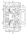
図1及び図2を参照するに、プレス機10は、フレーム12と、フレーム12の上部に前後方向(図1において、紙面に直角な方向)へ伸びる軸線の周りに回転可能に支持されたクランク軸14と、フレーム12の下部に載置されたボルスタ16と、上型を組み付けるスライド18とを含む。
【0016】
クランク軸14は、電動機のような駆動源(図示せず)により一定の速度で回転される。図示してはいないが、クランク軸14は、複数の主軸部においてフレーム16に支持されており、また一対の偏心主軸部を有する。両偏心軸部は、同じ偏心量を有するが、偏心方向がクランク軸14の周りに180度ずれている。
【0017】
スライド18は、フレーム12の中間部を上下方向へ移動可能に貫通する一対のロッド20の下端に取り付けられており、またフレーム12により上下方向への往復運動に規制されている。
【0018】
プレス機10は、また、クランク軸14の回転にともなってスライド18を上下方向へ往復移動させる一対の運動変換装置22と、一対の平衡重り24とを含む。運動変換装置22はクランク軸14を間にしてフレーム12の上部に対称的に配置されており、平衡重り24は運動変換装置22を間にしてフレーム12の上部に対称的に配置されている。
【0019】
各運動変換装置22は、屈伸可能に連結された上部及び下部レバー26,28を屈伸可能に連結された一対のリンク30,32によりクランク軸14に連結し、上部レバー26を位置調整機構34によりフレーム12に連結している。
【0020】
レバー26,28の連結軸線を形成する枢軸36及びリンク30,32の連結軸線を形成する枢軸38はクランク軸14の回転軸線と平行に伸びており、したがってレバー26,28及びリンク30,32はそれらの連結軸線に垂直な面内で屈伸可能である。上部及び下部レバー26及び28は、それぞれ、下端部及び上端部において枢軸により互いに連結されている。
【0021】
上部レバー26は、固定側支点として作用する軸線を有する枢軸40により上端部において位置調整機構34に連結されている。下部レバー28は、可動側支点として作用する軸線を有する枢軸42により下端部においてロッド22の上端部に連結されている。
【0022】
リンク30はクランク軸14の1つの偏心軸部に枢軸的に連結されており、リンク32は枢軸36により両レバー26,28の連結部に連結されている。上下方向における枢軸38の位置(すなわち、両リンク30,32の連結軸線の位置)は、規制具により水平方向に規制されている。そのような規制具は、上下方向へ伸びるT字状の補助リンク44と、補助リンク44の上端部に左右方向に間隔をおいた箇所から斜め下方へ八字状に伸びる一対の補助リンク46とを備える。
【0023】
補助リング44は、下端部において枢軸38によりリンク30,32の枢軸連結部に枢軸的に連結されている。両補助リンク46は、補助リンク44の上端部に左右方向に間隔をおいた箇所に前後方向へ伸びる枢軸により上端部において連結されており、またフレーム12に設けられたブラケット部48に前後方向へ伸びる枢軸により連結されている。
【0024】
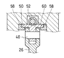
各位置調整機構34は、固定側支点を形成する枢軸40により上部レバー26の上端部に連結された回転体50と、回転体50を両レバー26,28を連結している枢軸36の周りに回転させる回転機構52とを備える。両位置調整機構34の回転機構52は、手動又は電動機により同期して同量回転される。
【0025】
図3及び図4に示す例では、回転体50は枢軸36の周りを弧状に伸びる外周面に外歯54を有する歯車を備え、回転機構52は回転体50の外歯と噛合するウォームねじ部56を有しかつブラケット部48を貫通している棒状部材を備える。
【0026】
回転体50は、上部レバー26への枢軸連結点(固定側支点)が枢軸36の周りの円弧に沿って角度的に回転移動するように、フレーム12に設けられた弧状の複数のガイドすなわち補助具58によりフレーム12に組み付けられている。
【0027】
図4に示すように、回転体50は、帯状に伸びる外周面を有しており、外歯54を外周面の幅方向の中央に形成しており、外周面の幅方向両縁部をフレーム12の円弧状の内面60と補助具58とに当接させている。
【0028】
各平衡重り24は、上下方向へ伸びており、また上端部及び下端部においてそれぞれ補助リンク62及び64によりブラケット部48及び可動側支点に枢軸的に連結されている。補助リング62及び64は、左右方向へ平行に伸びている。補助リンク64は、上下方向へ伸びる補助リンク66により長手方向中間部をフレーム12に枢軸的に連結されている。
【0029】
プレス機10において、クランク軸14が回転されると、クランク軸14の偏心軸部の回転にともなってリンク30が左右方向へ移動される。このとき、両リンク30,32の枢軸連結部の移動が補助レバー44,46により水平方向に規制されているから、リンク32が左右方向へ移動される。これにより、両レバー26,28の枢軸連結部が左右方向へ強制的に移動されて、両レバー26,28が屈伸運動をする。
【0030】
両レバー26,28が屈伸運動をすると、固定側支点(枢軸40)は移動しないが、可動側支点(枢軸42)は上下方向へ往復移動をする。これにより、スライド18は上下方向へ往復移動され、各平衡重り24はスライド18と180度移相して上下方向へ往復移動される。
【0031】
両レバー26,28の連結軸線(枢軸36)の周りにおける固定側支点の位置が変更されると、クランク軸14の回転にともなう両レバー26,28の屈曲角度範囲が変更される。これにより、スライド18の往復運動のストローク長さが変更される。
【0032】
ストローク長さを変更するとき、回転体50が回転機構52により枢軸36の周りに角度的に回転され、これにより上部レバー26は両レバー26,28の連結軸線の周りに角度的に回転される。しかし、このとき固定側支点の位置が両レバー26,28の連結軸線の周りに変更されるから、上下方向における両レバー26,28の連結軸線の位置は変化しない。これにより、ストローク長さを変更しても、下死点位置は変更されない。
【0033】
図5は、スライド18のストローク長さを変更したときのレバー26,28、リンク30,32、枢軸36,38,40,42、スライド18の位置関係を模式的に示す。図5において、(A),(C),(E)は両レバー26,28により形成される角度が最も大きくなる下死点にスライド18が変位された状態を示し、(B),(D),(F)は両レバー26,28により形成される角度が最も小さくなる上死点にスライド18が変位された状態を示す。
【0034】
図5から明らかなように、枢軸38の上下方向における位置が規制具により常に一定に規制されているから、枢軸40の位置を枢軸36の周りに変更しても、クランク軸14の回転軸線からスライド18の下端面までの距離L1は変化せず、したがって下死点位置は変化しない。
【0035】
これに対し、枢軸40の位置を変更すると、上死点位置及び下死点位置における両レバー26,28の角度が変化するから、枢軸36の周りにおける枢軸40の位置により、クランク軸14の回転軸線からスライド18の下端面までの距離L21,L22,L23が変化し、したがって上死点におけるスライド18の位置及びストローク長さは異なる。
【0036】
上記の結果、レバー26,28の枢軸連結点(枢軸36の中心)が移動されるから、クランク軸16の回転にともなうリンク30,32及びレバー26,28の屈曲位置及び屈曲角度が変更されて、スライド18の上下運動のストローク長さL01,L02,L03が変化する。それゆえに、回転機構34を回転させることにより、スライド18の上下運動のストローク長さを微細に調整することができる。
【0037】
上記実施例において、外歯歯車54を有する回転体を用いる代わりに、内歯歯車、爪車、スプロケット、タイミングプーリ等、他の平板状回転体を用いてもよい。また、ウォームねじの代わりに、回転体に応じて、小歯車、ラチェット、チェーン、タイミングプーリ、タイミングベルト等の他の部材を含む回転機構を用いてもよい。
【0038】
本発明は、上記実施例に限定されない。例えば、本発明は、上部スライドの移動方向が水平方向、斜めの方向等他の方向のプレス機にも適用することができる。それゆえに、本発明は、その趣旨を逸脱しない限り、種々変更することができる。
【図面の簡単な説明】
【図1】本発明に係るプレス機の一実施例を示す、一部を断面した正面図
【図2】図1に示すプレス機の上部の拡大図
【図3】位置調整機構の一実施例を示す図
【図4】図3におけるA−A線に沿って得た断面図である。
【図5】スライドのストローク長さを変更したときのスライドの高さ位置を説明するための図
【符号の説明】
10 プレス機
12 フレーム
14 クランク軸
16 ボルスタ
18 スライド
20 ロッド
22 スライド運動変換装置
24 平衡重り
26,28 レバー
30,32 リンク
34 位置調整機構
36,38,40,42 連結用の枢軸
44,46,62,64 補助リンク
50 回転体
52 回転機構
54 歯車
56 ウォームねじ[0001]
BACKGROUND OF THE INVENTION
The present invention relates to a press machine that reciprocates a slide by bending and stretching a pair of levers by rotation of a crankshaft.
[0002]
[Prior art]
As one of the press machines, there is a press machine using a link mechanism such as a knuckle mechanism or a toggle mechanism (for example, JP-A-10-109194). This press machine has a crankshaft rotated by a driving source, a link mechanism in which an upper lever having a fixed fulcrum and a lower lever having a movable fulcrum are pivotally connected to each other, and both levers are rotated by the crankshaft. And a position adjusting mechanism for connecting the fixed fulcrum to the frame so that the position of the fulcrum can be adjusted. The upper slide is connected to the movable fulcrum.
[0003]
The coupling mechanism couples the crankshaft and the coupling mechanism by a pair of links coupled so as to be able to bend and extend, and restricts the moving direction of the pivot coupling point of both links in the horizontal direction by a plurality of auxiliary links. The position adjusting mechanism moves the fixed fulcrum in the moving direction of the pivot connection point of both links, thereby changing the bending angle of both levers and changing the stroke length of the slide.
[0004]
[Problems to be solved]
However, in the above conventional press machine, the moving direction of the fixed fulcrum is horizontal, so when the stroke length is changed, the lever having the fixed fulcrum is rotated angularly around the pivot connection point of both levers. The pivot connecting point of both levers is displaced in the vertical direction, so that the bottom dead center position of the upper slide changes. When the bottom dead center position changes in this way, the positional relationship between the upper and lower molds changes. Therefore, the positional relationship between the upper and lower molds must be adjusted each time the stroke length is adjusted.
[0005]
Therefore, in this type of press, it is important that the bottom dead center position does not change even if the slide stroke length is changed.
[0006]
[Solution, action and effect]
The press according to the present invention includes a frame, a crankshaft disposed on the frame so as to be rotatable around an axis extending in a first direction, and a second direction extending in a direction intersecting the first direction. A slide disposed on the frame so as to be capable of reciprocating; and one or more motion converters for reciprocating the slide as the crankshaft rotates.
[0007]
The motion conversion device interconnects a first lever having a fixed fulcrum and a second lever having a movable fulcrum connected to the slide so as to be capable of bending and extending around an axis extending in the first direction. A link mechanism, a connecting mechanism for causing the levers to bend and extend as the crankshaft rotates, and a position adjusting mechanism for connecting the fixed side fulcrum to the frame, around the connecting axis of the levers. And a position adjusting mechanism that adjusts the position of the fixed-side fulcrum on an arc that is convex on the side opposite to the slide side.
[0008]
When both levers bend and extend, the fixed side fulcrum does not move, but the movable side fulcrum reciprocates in the second direction, whereby the slide is reciprocated in the second direction. When the position of the fixed fulcrum around the connecting axis of both levers is changed, the angle of the bending and stretching movements of both levers is changed, thereby changing the stroke length of the reciprocating movement of the slide.
[0009]
When changing the stroke length, the first lever is rotated angularly around the connecting axis of both levers, but the position of the fixed fulcrum is changed around the connecting axis of both levers. The position of the connecting axis does not change. Thereby, even if the stroke length is changed, the bottom dead center position is not changed.
[0010]
The position adjusting mechanism is a rotating body pivotally connected to the first lever at the fixed fulcrum, and the pivot connecting point to the first lever is rotatable around the connecting axis of the two levers. And a rotating mechanism that rotates the rotating body around the connecting axis of the two levers. In this way, the position of the rotating body around the connecting axis of the two levers can be finely adjusted. Therefore, the slide stroke length can be finely adjusted.
[0011]
The rotating body may include a gear having external teeth extending in an arc around the connecting axis of the two levers, and the rotating mechanism may include a worm screw portion that meshes with the gear. In this way, the position of the gear around the connecting axis of both levers can be adjusted by the worm screw, so that the stroke length of the slide can be adjusted more finely.
[0012]
The connection mechanism includes a first link pivotally connected to the eccentric shaft portion of the crankshaft, a second link pivotally connected to the first link and the levers, and the second link. And a restricting tool for restricting the position of the pivot connecting portion of both the links in the direction of the. In this way, the positions of the pivot connecting portions of the first and second links in the second direction are restricted, so that the bending motion of the first and second levers and the first and second links is smooth. And the reciprocating motion of the slide becomes smooth.
[0013]
The restricting tool is a first auxiliary link extending in a second direction, the first auxiliary link pivotally connected to the pivot coupling portion of the first and second links at the lower end, and the first auxiliary link A pair of second links pivotally connected to one end of one auxiliary link spaced apart in a third direction intersecting the first and second directions and pivotally connected to the frame; And an auxiliary link.
[0014]
In addition, the balance includes a pair of balance weights arranged on the outside of the motion conversion device, and each balance weight is pivotally connected to the frame and the movable side fulcrum by third and fourth auxiliary links at the upper end and the lower end, respectively. Each fourth auxiliary link is pivotally connected to the frame by a fifth auxiliary link at an intermediate portion thereof. In this way, the vibration of the press machine is remarkably reduced.
[0015]
DETAILED DESCRIPTION OF THE INVENTION
Referring to FIGS. 1 and 2, a press machine 10 includes a
[0016]
The
[0017]
The
[0018]
The press machine 10 also includes a pair of
[0019]
Each
[0020]
The
[0021]
The
[0022]
The
[0023]
The
[0024]
Each
[0025]
In the example shown in FIGS. 3 and 4, the rotating
[0026]
The rotating
[0027]
As shown in FIG. 4, the rotating
[0028]
Each
[0029]
In the press 10, when the
[0030]
When the
[0031]
When the position of the fixed fulcrum around the connecting axis (the pivot axis 36) of both
[0032]
When changing the stroke length, the rotating
[0033]
FIG. 5 schematically shows the positional relationship among the
[0034]
As apparent from FIG. 5, since the position of the
[0035]
On the other hand, when the position of the
[0036]
As a result, the pivot connecting point of the
[0037]
In the above embodiment, instead of using the rotating body having the
[0038]
The present invention is not limited to the above embodiments. For example, the present invention can be applied to a pressing machine in which the moving direction of the upper slide is in another direction such as a horizontal direction or an oblique direction. Therefore, the present invention can be variously modified without departing from the gist thereof.
[Brief description of the drawings]
FIG. 1 is a partially sectional front view showing an embodiment of a press machine according to the present invention. FIG. 2 is an enlarged view of an upper portion of the press machine shown in FIG. 1. FIG. FIG. 4 is a cross-sectional view taken along line AA in FIG.
FIG. 5 is a diagram for explaining the slide height position when the slide stroke length is changed.
DESCRIPTION OF SYMBOLS 10
Claims (6)
前記運動変換装置は、固定側支点を有する第1のレバー及び前記スライドに連結された可動側支点を有する第2のレバーを前記第1の方向へ伸びる軸線の周りに屈伸運動可能に相互に連結したリンク機構と、前記クランク軸の回転にともなって前記両レバーに屈伸運動をさせる連結機構と、前記固定側支点を前記フレームに連結する位置調整機構であって前記両レバーの連結軸線の周りにあって前記スライドの側と反対の側に凸となる円弧上における前記固定側支点の位置を調整する位置調整機構とを備える、プレス機。A frame, a crankshaft disposed on the frame for rotation about an axis extending in a first direction, and a reciprocating motion in a second direction extending in a direction intersecting the first direction. And one or more motion converters that reciprocate the slide as the crankshaft rotates,
The motion conversion device interconnects a first lever having a fixed fulcrum and a second lever having a movable fulcrum connected to the slide so as to be capable of bending and extending around an axis extending in the first direction. A link mechanism, a connecting mechanism for causing the levers to bend and extend as the crankshaft rotates, and a position adjusting mechanism for connecting the fixed side fulcrum to the frame, around the connecting axis of the levers. A press machine comprising: a position adjusting mechanism that adjusts a position of the fixed side fulcrum on an arc that is convex on the side opposite to the slide side.
Priority Applications (1)
| Application Number | Priority Date | Filing Date | Title |
|---|---|---|---|
| JP13573299A JP4274629B2 (en) | 1999-05-17 | 1999-05-17 | Press machine |
Applications Claiming Priority (1)
| Application Number | Priority Date | Filing Date | Title |
|---|---|---|---|
| JP13573299A JP4274629B2 (en) | 1999-05-17 | 1999-05-17 | Press machine |
Publications (3)
| Publication Number | Publication Date |
|---|---|
| JP2000317688A JP2000317688A (en) | 2000-11-21 |
| JP2000317688A5 JP2000317688A5 (en) | 2006-04-20 |
| JP4274629B2 true JP4274629B2 (en) | 2009-06-10 |
Family
ID=15158590
Family Applications (1)
| Application Number | Title | Priority Date | Filing Date |
|---|---|---|---|
| JP13573299A Expired - Fee Related JP4274629B2 (en) | 1999-05-17 | 1999-05-17 | Press machine |
Country Status (1)
| Country | Link |
|---|---|
| JP (1) | JP4274629B2 (en) |
Cited By (1)
| Publication number | Priority date | Publication date | Assignee | Title |
|---|---|---|---|---|
| CN102975386A (en) * | 2012-11-27 | 2013-03-20 | 南京理工大学 | High-speed precise numerical-control stamping machine mechanismstructure capable of realizing dynamic lower dead point precision compensation |
Families Citing this family (4)
| Publication number | Priority date | Publication date | Assignee | Title |
|---|---|---|---|---|
| JP5412326B2 (en) * | 2010-03-02 | 2014-02-12 | 株式会社山田ドビー | Press machine |
| JP5412327B2 (en) * | 2010-03-02 | 2014-02-12 | 株式会社山田ドビー | Press machine |
| JP5462029B2 (en) * | 2010-03-02 | 2014-04-02 | 株式会社山田ドビー | Press machine |
| CN106863875B (en) * | 2017-03-29 | 2018-12-25 | 扬力集团股份有限公司 | A kind of stroke of a press and height of packing compact regulating mechanism |
-
1999
- 1999-05-17 JP JP13573299A patent/JP4274629B2/en not_active Expired - Fee Related
Cited By (1)
| Publication number | Priority date | Publication date | Assignee | Title |
|---|---|---|---|---|
| CN102975386A (en) * | 2012-11-27 | 2013-03-20 | 南京理工大学 | High-speed precise numerical-control stamping machine mechanismstructure capable of realizing dynamic lower dead point precision compensation |
Also Published As
| Publication number | Publication date |
|---|---|
| JP2000317688A (en) | 2000-11-21 |
Similar Documents
| Publication | Publication Date | Title |
|---|---|---|
| JP3451214B2 (en) | Press machine | |
| JP4404984B2 (en) | Press machine | |
| JPH06114599A (en) | Power transmission device of press machine | |
| JP4274629B2 (en) | Press machine | |
| JP3773399B2 (en) | Press machine | |
| JP2003080397A (en) | Press | |
| JP4291896B2 (en) | Press machine | |
| JP2003048099A (en) | Press | |
| JP2003048099A5 (en) | ||
| JP2003205394A (en) | Slide driving device of press machine | |
| JPH10109194A (en) | Device for driving slide of mechanical press by using link | |
| JP3689605B2 (en) | Press machine | |
| JP2649318B2 (en) | Press machine | |
| JP5654746B2 (en) | Press machine | |
| JP3910289B2 (en) | Press machine | |
| JP3889930B2 (en) | Power transmission device for press machine | |
| JP5412326B2 (en) | Press machine | |
| JP2002066797A (en) | Press | |
| EP1043148B1 (en) | Press machine | |
| JP4233683B2 (en) | Mechanical press device | |
| CN2920636Y (en) | Punching machine double-eccentric stroke regulator | |
| JPH0644552Y2 (en) | Link press | |
| JP2002346798A (en) | Driving device for crank press | |
| JP2000288790A (en) | Press machine | |
| JPH1071619A (en) | Table driving apparatus for molding machine |
Legal Events
| Date | Code | Title | Description |
|---|---|---|---|
| A521 | Written amendment |
Free format text: JAPANESE INTERMEDIATE CODE: A523 Effective date: 20060306 |
|
| A621 | Written request for application examination |
Free format text: JAPANESE INTERMEDIATE CODE: A621 Effective date: 20060306 |
|
| A977 | Report on retrieval |
Free format text: JAPANESE INTERMEDIATE CODE: A971007 Effective date: 20081110 |
|
| A131 | Notification of reasons for refusal |
Free format text: JAPANESE INTERMEDIATE CODE: A131 Effective date: 20081118 |
|
| A521 | Written amendment |
Free format text: JAPANESE INTERMEDIATE CODE: A523 Effective date: 20090108 |
|
| TRDD | Decision of grant or rejection written | ||
| A01 | Written decision to grant a patent or to grant a registration (utility model) |
Free format text: JAPANESE INTERMEDIATE CODE: A01 Effective date: 20090210 |
|
| A01 | Written decision to grant a patent or to grant a registration (utility model) |
Free format text: JAPANESE INTERMEDIATE CODE: A01 |
|
| A61 | First payment of annual fees (during grant procedure) |
Free format text: JAPANESE INTERMEDIATE CODE: A61 Effective date: 20090303 |
|
| R150 | Certificate of patent or registration of utility model |
Ref document number: 4274629 Country of ref document: JP Free format text: JAPANESE INTERMEDIATE CODE: R150 Free format text: JAPANESE INTERMEDIATE CODE: R150 |
|
| FPAY | Renewal fee payment (event date is renewal date of database) |
Free format text: PAYMENT UNTIL: 20120313 Year of fee payment: 3 |
|
| FPAY | Renewal fee payment (event date is renewal date of database) |
Free format text: PAYMENT UNTIL: 20120313 Year of fee payment: 3 |
|
| FPAY | Renewal fee payment (event date is renewal date of database) |
Free format text: PAYMENT UNTIL: 20130313 Year of fee payment: 4 |
|
| R250 | Receipt of annual fees |
Free format text: JAPANESE INTERMEDIATE CODE: R250 |
|
| FPAY | Renewal fee payment (event date is renewal date of database) |
Free format text: PAYMENT UNTIL: 20130313 Year of fee payment: 4 |
|
| FPAY | Renewal fee payment (event date is renewal date of database) |
Free format text: PAYMENT UNTIL: 20140313 Year of fee payment: 5 |
|
| R250 | Receipt of annual fees |
Free format text: JAPANESE INTERMEDIATE CODE: R250 |
|
| R250 | Receipt of annual fees |
Free format text: JAPANESE INTERMEDIATE CODE: R250 |
|
| R250 | Receipt of annual fees |
Free format text: JAPANESE INTERMEDIATE CODE: R250 |
|
| R250 | Receipt of annual fees |
Free format text: JAPANESE INTERMEDIATE CODE: R250 |
|
| R250 | Receipt of annual fees |
Free format text: JAPANESE INTERMEDIATE CODE: R250 |
|
| R250 | Receipt of annual fees |
Free format text: JAPANESE INTERMEDIATE CODE: R250 |
|
| LAPS | Cancellation because of no payment of annual fees |