JP4268043B2 - High sensitivity particle detector - Google Patents
High sensitivity particle detector Download PDFInfo
- Publication number
- JP4268043B2 JP4268043B2 JP2003531431A JP2003531431A JP4268043B2 JP 4268043 B2 JP4268043 B2 JP 4268043B2 JP 2003531431 A JP2003531431 A JP 2003531431A JP 2003531431 A JP2003531431 A JP 2003531431A JP 4268043 B2 JP4268043 B2 JP 4268043B2
- Authority
- JP
- Japan
- Prior art keywords
- radiation
- particle
- particle detection
- detection method
- generating means
- Prior art date
- Legal status (The legal status is an assumption and is not a legal conclusion. Google has not performed a legal analysis and makes no representation as to the accuracy of the status listed.)
- Expired - Lifetime
Links
Images


Classifications
-
- G—PHYSICS
- G08—SIGNALLING
- G08B—SIGNALLING OR CALLING SYSTEMS; ORDER TELEGRAPHS; ALARM SYSTEMS
- G08B17/00—Fire alarms; Alarms responsive to explosion
- G08B17/10—Actuation by presence of smoke or gases, e.g. automatic alarm devices for analysing flowing fluid materials by the use of optical means
- G08B17/103—Actuation by presence of smoke or gases, e.g. automatic alarm devices for analysing flowing fluid materials by the use of optical means using a light emitting and receiving device
- G08B17/107—Actuation by presence of smoke or gases, e.g. automatic alarm devices for analysing flowing fluid materials by the use of optical means using a light emitting and receiving device for detecting light-scattering due to smoke
-
- G—PHYSICS
- G08—SIGNALLING
- G08B—SIGNALLING OR CALLING SYSTEMS; ORDER TELEGRAPHS; ALARM SYSTEMS
- G08B17/00—Fire alarms; Alarms responsive to explosion
- G08B17/10—Actuation by presence of smoke or gases, e.g. automatic alarm devices for analysing flowing fluid materials by the use of optical means
- G08B17/11—Actuation by presence of smoke or gases, e.g. automatic alarm devices for analysing flowing fluid materials by the use of optical means using an ionisation chamber for detecting smoke or gas
- G08B17/113—Constructional details
Abstract
Description
【0001】
[技術の分野]
本発明は、広く高感度粒子検出器に関する。本発明の実施例は、例としてだけの煙粒子の存在を検出するためのものとしてより詳細に記述される。
【0002】
[背景技術]
英国特許明細書第2330410号は、青色および赤外の放射を交互に活性化する煙粒子検出器を開示している。受信された青色および赤外の放射を表す信号は、煙の存在を決めるために比較される。
【0003】
[発明の開示]
本発明の第1の形態によれば、それぞれが作用するとき、散乱ボリュームに実質的に同様の予め定められた経路に沿って第1および第2の放射をそれぞれ発する第1の放射発生手段および第2の放射発生手段と、前記散乱ボリューム内の粒子の存在によって該散乱ボリュームから前方散乱された前記第1の放射を受信および感知すると共に、前記散乱ボリューム内の粒子の存在によって該散乱ボリュームから前方散乱された前記第2の放射を受信および感知する放射感知手段と、前記受信および感知された第1の放射に応答して該受信および感知された第1の放射に従った第1の信号を生成すると共に、前記受信および感知された第2の放射に応答して該受信および感知された第2の放射に従った第2の信号を生成する制御手段と、前記第1および第2の信号を比較し、該比較が前記粒子は予め定められたタイプであることを示し、且つ、該比較が他を示さない場合、警報出力を生成する出力手段と、を備え、前記制御手段は、前記第1の信号が予め定められた値を超えるまで、前記第2の放射発生手段が作用しないように維持するために前記第1の放射発生手段が作用させられるときに作用し、それから、前記第2の放射発生手段を作用させることを特徴とする粒子検出装置が提供される。
本発明の第2の形態によれば、第1および第2の放射を実質的に同様の予め定められた経路に沿って散乱ボリューム内にそれぞれ発するのを制御可能として行うステップと、前記散乱ボリューム内の粒子の存在によって該散乱ボリュームから前方散乱された前記第1の放射を受信および感知すると共に、前記散乱ボリューム内の粒子の存在によって該散乱ボリュームから前方散乱された前記第2の放射を受信および感知するステップと、前記受信および感知された第1の放射に応答して該受信および感知された第1の放射に従った第1の信号を生成するように処理するステップと、前記受信および感知された第2の放射に応答して該受信および感知された第2の放射に従った第2の信号を生成するように処理するステップと、前記第1および第2の信号を比較し、該比較が前記粒子は予め定められたタイプであることを示し、且つ、該比較が他を示さない場合、警報出力を生成するステップと、を備え、前記第1の放射が発せられるのが許される間、前記第1の信号が予め定められた値を超えるまで、前記第2の放射の発生を妨げ、それから、前記第2の放射の発生を許すことにより特徴付けられる粒子検出方法が提供される。
本発明によれば、それぞれが作用するとき、散乱ボリュームに実質的に同様の予め定められた経路に沿って第1および第2の放射をそれぞれ発する第1の放射発生手段および第2の放射発生手段と、前記散乱ボリューム内の粒子の存在によって該散乱ボリュームから前方散乱された前記第1の放射を受信および感知すると共に、前記散乱ボリューム内の粒子の存在によって該散乱ボリュームから前方散乱された前記第2の放射を受信および感知する放射感知手段と、前記受信および感知された第1の放射に応答して該受信および感知された第1の放射に従った第1の信号を生成すると共に、前記受信および感知された第2の放射に応答して該受信および感知された第2の放射に従った第2の信号を生成する制御手段と、前記第1および第2の信号を比較し、該比較が前記粒子は予め定められたタイプであることを示し、且つ、該比較が他を示さない場合、警報出力を生成する出力手段とを備え、前記第1の信号が予め定められた値を超えるまで、前記第2の放射発生手段が作用しないように維持するために前記第1の放射発生手段が前記第2の放射発生手段が作用するときに作用させ、それから、前記第2の放射発生手段を作用させる制御手段により特徴付けられる粒子検出装置が提供される。
【0004】
また、本発明によれば、第1および第2の放射を実質的に同様の予め定められた経路に沿って散乱ボリューム内にそれぞれ発するのを制御可能として行うステップと、前記散乱ボリューム内の粒子の存在によって該散乱ボリュームから前方散乱された前記第1の放射を受信および感知すると共に、前記散乱ボリューム内の粒子の存在によって該散乱ボリュームから前方散乱された前記第2の放射を受信および感知するステップと、前記受信および感知された第1の放射に応答して該受信および感知された第1の放射に従った第1の信号を生成するように処理するステップと、前記受信および感知された第2の放射に応答して該受信および感知された第2の放射に従った第2の信号を生成するように処理するステップと、前記第1および第2の信号を比較し、該比較が前記粒子は予め定められたタイプであることを示し、且つ、該比較が他を示さない場合、警報出力を生成するステップとを備え、前記第1の放射が発せられるのが許される間、前記第1の信号が予め定められた値を超えるまで、前記第2の放射の発生を妨げ、それから、前記第2の放射の発生を許すことにより特徴付けられる粒子検出方法も提供される。
【0005】
[発明の実施の形態]
以下、本発明に係る高感度粒子検出装置および方法が、単なる例としてだけの添付図面を参照して説明される。
【0006】
同様の装置および方法を使用して他の粒子を検出することはできるが、記述される装置および方法は、放射散乱技術を使用して空気中における煙粒子の存在を検出するためのものとして説明される。この装置および方法は、1メートル当たり少なくとも0.2%の煙密度における煙粒子の存在を検出することを狙っている。そのような装置の主たる使用は、初期火災を検出するためである。
【0007】
装置1(図1参照)は、参照符号7で示されるように、経路5に沿ってビームスプリッタ17を介して進む放射を行う2つの放射源3,3Aを備える。放射7は、ビームダンプ(beam dump)11に向かってボリューム9を介して進む。楕円形ミラー13は、ボリューム9(以下に論じられるように、予め定められた前方散乱角の範囲内)に存在する煙粒子によって散乱された放射を集めるように、且つ、そのような放射をシリコンフォトダイオードのような検出器15上にフォーカスさせるように位置決めされる。
【0008】
放射源3は、約400nm〜500nmの間の比較的短い波長、すなわち、青色の可視光で放射を行う。好ましくは、放射源3は、470nmで放射を発するLEDである。放射源3Aは、約880nmで赤外放射を発し、これもLEDであり得る。検出器15は、両方の放射源により発せられた放射に感応する。
【0009】
使用において、散乱ボリューム9における粒子の存在は、予め定められた角度範囲を介して散乱される放射7を生じる。楕円形ミラー13は、45°よりも小さい前方散乱角で、特に、約10°〜35°の間の散乱角で散乱された光がミラー13によって集められるように位置決めされる。ミラー13は、散乱ボリュームからそれらの角度で散乱された光を、対応する信号を生成するシリコンフォトダイオード15上に、入射する放射方向に垂直な全ての面にフォーカスさせる。この配置は、フォトダイオード15に入射する放射を最大限にする。
【0010】
散乱されない如何なる放射も投射されて実質的にビームダンプ11によって捕らえられ、シリコンフォトダイオード15によって対応する信号が生成されることはない。
【0011】
シリコンフォトダイオード15からの出力は、ライン18上の制御システム16に供給される。制御システム16は、LED3および3Aの通電を制御する。説明される手法において、制御システム16は、フォトダイオード15から受信された出力を処理し、それぞれLED3を起源とする散乱放射に応答するフォトダイオード15により生成された出力、および、LED3Aを起源とする散乱放射に応答するフォトダイオード15により生成された出力に対応するライン21および23上の信号を生成する。
【0012】
ライン21および23は、比較器25に供給されると共に、閾値ユニット26,28および29に供給される。
【0013】
図2における曲線Aは、青色光(すなわち、光源3からの光)の1メートル当たりで吸収された百分率として表された煙の光吸収率の異なる度合いの検出器15の出力を示す。曲線Bは、同じ散乱角だが放射の波長が880nm(すなわち、光源3Aからの光)の時の対応する検出器の出力を示す。各々の場合、前方散乱角の範囲は、同じ(約10°〜35°の間)である。テストのための煙は、綿を燻すことによって生成した。
【0014】
図2は、光源3Aからの赤外放射に応答して生成された検出器の出力と比較して、光源3からの青色の可視光に応答した検出器からの明らかに大きな出力が検出可能であり、1メートル当たり0.2%といった低い煙密度でフォトダイオード15から生成され得ることを明瞭に示している。
【0015】
図3は、異なる波長の光を使用した前方散乱角に対する煙の典型的な粒子サイズ分布の計算された散乱利得をプロットしている。散乱利得は、個々の粒子に当たる光の断片としての単位立体角(unit solid angle)に散乱する光の総量である。曲線Aは、光源3によって生成された青色の可視光に対応し、また、曲線Bは、光源3Aによって生成された赤外放射に対応する。
【0016】
図3は、散乱利得の増加は約45°よりも小さい散乱角においてはより一層明白であるが、約155°までの散乱角に対する青色の可視光(曲線A)に応答する散乱利得がどのように赤外放射(曲線B)に応答する散乱利得よりも明らかに大きいかを示している。
【0017】
従って、図2および図3における曲線Aは、青色の可視光(400nm〜500nmの間の放射)の使用および低い散乱角(約10°〜35°の間)の使用の組み合わせが、どのように感度における明らかな増加を生じるかを示している。
【0018】
煙検出器は、凝結水や埃といった大きな煙霧質の存在の影響を受けやすく誤った警報を発し易い。図4は、凝結水の霧の典型的なサイズ分布を有する粒子である点を除いて、図3に対応する。曲線Aは、光源3からの青色の可視光に応答した散乱利得を示し、また、曲線Bは、光源3Aからの赤外放射に応答した散乱利得を示す。図4における曲線AおよびBは、少なくとも約15°〜30°の散乱角では、テストされた両方の波長と実質的に等しい散乱利得を示す。従って、図3および図4の比較は、赤外放射に応答したフォトダイオード信号に対する青色に応答したフォトダイオード信号の比が、凝結水の霧のような『妨害となる(nuisance)』煙霧質に対するものよりも煙粒子に対するものの方が大きいことを示している。
【0019】
使用において、検出装置は、2つのモードの両方で動作し得る。
【0020】
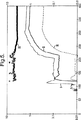
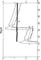
まず、検出モードにおいて、制御システム16は、異なる周波数で連続的にLED3および3Aを駆動し、そして、狭いバンドまたは固定した増幅器に分割する。増幅器は、制御システム16の一部を構成し、フォトダイオード15からの出力に応答してそれぞれ散乱青色光および散乱赤外放射に対応する信号でライン21および23を活性化する。ライン21および23上の信号は、ライン23上の信号の振幅に対するライン21上の信号の振幅の比を測定する比較器25に供給される。図5および図6は、このモードにおける装置の動作を説明する。
【0021】
図5および図6において、横軸は時間を示し、左側の縦軸は1メートル当たり吸収された光の百分率で表された可視の光吸収率を示し、そして、右側の縦軸は図1における検出器15の出力を示している。ここで、左右の軸は対数目盛である。
【0022】
図5は、煙が100秒で5秒間放出され、それから200〜300秒の間に100秒間放出されたとき、吸収が煙(この場合、綿を燻すことによって生成した灰色の煙)によって生じたときに得られた結果を示す。図6において、吸収は、非煙発生源によって、この場合、ヘアスプレーエアゾールによって生じている。100秒で1秒間スプレーし、そして、200秒で10秒間スプレーする。
【0023】
図5において、曲線Iは、吸収率をプロットしている。曲線IIは、光源3から発せられた青色光に応答する検出器15の出力をプロットしている。曲線IIIは、光源3Aから発せられた赤外放射に応答する検出器15の出力をプロットしている。ここで、散乱赤外放射(曲線III)に応答する検出器出力が、散乱青色光(曲線II)に応答する検出器出力よりも十分に小さいことが分かる。曲線IVは、発せられた放射が赤外(曲線III)の検出器出力に対する発せられた放射が青色光(曲線II)の検出器出力の比を示している。この比は、明らかに1よりも大きい。
【0024】
図6において、曲線I,II,IIIおよびIVは、図5と同様のものを示している。ここで、曲線IVで示される比が明らかに1よりも小さいことに注意されたい。
【0025】
従って、もし、比較ユニット25が、自身が測定した比が予め定められた値よりも大きいと判定するならば、これは、煙による吸収であることを示し、そして、比較ユニットがライン30に警報信号を生成する。しかしながら、もし、測定された比が1よりも小さいならば、これは、非煙による吸収であることを示し、そして、警報信号は生成されない。従って、ライン21および23の検出モードにおいて生成された信号の比を測定することによって、非煙による吸収に対して非常に優れた識別力で、非常に高感度の煙検出が生成される。比較ユニット25からライン30上に出力される警報信号は、もし、ライン21上の信号(すなわち、受信された散乱青色光に応答するフォトダイオード15によって生成された信号)の大きさが、閾値ユニット29によって固定された予め定められた閾値を超えると、ライン34上の出力を受け取るアラームユニット32に供給される。もし、アラームユニット32がライン30および34の両方の信号を受け取ると、該アラームユニットは、アラーム出力を生成する。
【0026】
しかしながら、記述されている検出装置の構成によれば、装置は、モニターモードにおいても動作することができ、事実、通常はこのモニターモードで動作する。モニターモードにおいて、制御システム16は、光源3を、スイッチオフ、或いは、ことによると非常に遅いレートのパルスに維持する。しかしながら、このモードの間、制御システム部16は、周期的に赤外光源3Aを通電する。光源3Aは、十分な強さで通電されるかも知れないが、非常に短い期間で非常に遅い発光比、例えば、1秒当たり約1回程度で通電される。光源3Aは、モニターモードの間だけ、そして、比較的に遅い発光比で短い期間だけ通電されるので、このモニターモードにおける電力消費は小さい。このように通電されるとき、赤外LEDは長い寿命を持つことが知られている。
【0027】
モニターモードにおいて、制御システム16は、検出器15からの出力をモニタする。ボリューム9内で如何なる吸収も存在しないならば、そのような出力はもちろん存在しない。しかしながら、何らかの吸収が存在する場合には、幾らかの赤外放射が検出器15上に散乱され、対応する出力がライン18上に生成されることになる。制御システム16は、対応する信号をライン23上に(好適な同期型増幅器を使用して)生成し、そして、この信号の大きさが閾値ユニット28において予め定められた閾値と比較される。もし、その予め定められた閾値が超えられると、ライン36上の信号は、制御システム16に対して、モニターモードの間、赤外の光源3Aのパルス周波数よりも大きいそれぞれ異なった周波数のパルスで両方の光源3および3Aを駆動する上述した検出モードに装置を切り替えさせる。既に説明したように、比較ユニット25は、それぞれライン21および23上に生成された信号の間の比を測定し、それにより、システムは、煙粒子の検出および非煙吸収に対する判定を極めて高感度で動作する。
【0028】
従って、このとき、青色光を生成する光源3は、高感度の煙の検出および判定が要求される状態の時にだけ通電される。従って、どうしても低い寿命の青色光発生用LED3の悪影響を低減すると共に、電力消費が最小化される。
【0029】
モニターモードにおいて、赤外用LED3Aがパルス駆動される比、および、システムを検出モードに切り替えるためにフォトダイオードの出力が超えなければならない閾値ユニット28により与えられた閾値は、装置の特別な適用において分かっているリスクに従って設定される。高感度を維持するために、この閾値は、通常、低いレベルに設定される。しかしながら、誤ったアラームに対する用心のために、制御システムは、フォトダイオード15の出力が、装置が検出モードに切り替わる前に赤外用LED3Aからの出力パルスの予め定められた数(例えば、2つ、或いは、それ以上)の閾値を超えなければならないように設定され得る。
【0030】
装置がモニターモードから検出モードに切り替えられたとき、検出器15によって受信された散乱青色光に対応するライン21上の信号が閾値ユニット26によって設定された予め定められた閾値よりも低くなる(そして、好ましくは、少なくとも予め定められた時間だけその閾値よりも低いままである)か、或いは、比較ユニット25により測定された比が、火災警報を示すアラーム出力が生成されるレベルよりも高くなるかのいずれかまで、装置は検出モードに維持される。
【0031】
装置は、比較ユニット25から出力された比が、アラームレベルより低いときには、自動的にモニターモードに復帰するように構成することができる。或いは、代わりに、マニュアルリセットが必要になる。
【0032】
ボリューム9内が一般に汚れた環境であるといった或る決まった環境において、装置は、2つのモードの間で繰り返し切り替わるようになるかも知れない。そのため、ボリューム9内に汚れが存在するが非煙である環境において、比較ユニット25の出力が、吸収は非煙の吸収であることを示すとき、装置は、モニターモードから検出モードに切り替わるが、その後、直ちにモニターモードに復帰すし、この切り替え動作の繰り返しを継続することになる。そのような環境において、制御システム16は、検出器を検出モードに切り替える前に、検出器15の出力がモニターモードを超えなければならない閾値ユニット28の閾値を自動的に増大するように構成され得る。或いは、代わりに、制御システムは、検出モードにおける時間消費を制限するような環境に配置することができる。
【0033】
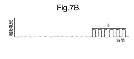
さらに、装置の動作が、図7および図8を参照して記述される。
【0034】
図7は、時間を表す縦軸およびLED3またはLED3Aを介して流れる駆動電流を表す横軸を有する図表である。ここで、プロットAは赤外用LED3Aのパルスを示す。期間Iに示されるように、装置は、LED3Aが比較的に高い電流であるがめったにないパルスで駆動されるモニターモードで動作している。時間t1において、フォトダイオード15の出力は、散乱赤外放射に応答し、閾値ユニット28によって設定された予め定められた閾値に到達し、その後、装置は、検出モードに切り替わる。従って、期間IIに示されるように、装置が検出モードになっているとき、図表は、赤外用LED3Aが低い電流振幅だがより高い周波数でパルス駆動されることを示している。同様に、同じ期間(プロットB)、青色LED3は、赤外用LED3Aの周波数とは異なる周波数でパルス駆動される。
【0035】
開始処理(ステップA)の後、装置は、最初に、赤外用LED3Aが低いレート(例えば、毎秒ごと)で駆動されるモニターモードで動作する(ステップB)。制御システム16は、何らかの受信された散乱赤外放射に応答する検出器15の出力が第1の閾値(閾値1:閾値ユニット28により適用された閾値)を超えたかどうかをチェックする(ステップC)。もし、この閾値が超えられていなければ、装置は、モニターモードにとどまる。しかしながら、もし、閾値が超えられていたならば、装置は、検出モードに入り(ステップD)、両方のLED3および3Aが異なる周波数でパルス駆動される。
【0036】
説明された手法において、制御システム16におけるロックイン増幅器は、LED3からの青色放射およびLED3Aからの赤外放射に応答する検出器出力に対応して、ライン21および23上に信号を生成する。比較ユニット25は、ライン23上の信号振幅に対するライン21上の信号振幅の比が1よりも大きいかどうかをチェックする(ステップE)。もし、その比が1を超えていなければ、制御システム16は、ライン21上の信号振幅が第2の予め定められた閾値(閾値2:閾値ユニット26により適用された閾値)を超えているかどうかをチェックする(ステップF)。もし、閾値2が超えられていたならば、装置は、検出モードにとどまる。もし、閾値2が超えられていなければ、装置は、モニターモードに復帰する。
【0037】
もし、ステップEにおいて、比較ユニット25によって測定された比が1よりも大きいと判定されると、装置は、ライン21上の信号振幅が閾値ユニット29により適用される閾値(閾値3)を超えているかどうかをチェックする(ステップG)。もし、この閾値が超えられていなければ、アラーム出力は生成されない。しかしながら、閾値3が超えられていたならば、警報が生成される(ステップH)。この信号は、アラームユニット32(図1)に適切なアラーム出力を生成させる(ステップI)。
【0038】
ステップJにおいて、警報信号がまだ生成されているかどうかのチェックが行われる。もし、警報信号がもう生成されていなければ、検出器は、モニターモードに復帰する。しかしながら、もし、警報信号がまだ生成されているならば、アラーム出力(ステップI)は維持される。
【0039】
本装置で使用される赤外放射は、必ずしも880nmである必要はない。
【0040】
変形において、図1の分割された光発生器3,3Aおよびビームスプリッタ17の代わりにデュアルLED配置が使用されるかも知れない。
【0041】
他の変形において、非常に高感度が要求されない場合には、図1の楕円形ミラー13は省かれ、散乱放射を集めるための複雑に入り組んだ配置によって取り替えることができるであろう。
【図面の簡単な説明】
【図1】 装置の一構成の概略図である。
【図2】 図1の装置の動作および長所を説明するためのグラフを示す図である。
【図3】 図1の装置の動作および長所を説明するためのグラフを示す図である。
【図4】 図1の装置の動作および長所を説明するためのグラフを示す図である。
【図5】 図1の装置の動作および長所を説明するためのグラフを示す図である。
【図6】 図1の装置の動作および長所を説明するためのグラフを示す図である。
【図7】 図1の装置の動作および長所を説明するためのグラフを示す図である。
【図8】 図1の装置の動作をさらに説明するためのフローチャートである。[0001]
[Technical field]
The present invention relates generally to highly sensitive particle detectors. Embodiments of the present invention will be described in more detail as detecting the presence of smoke particles by way of example only.
[0002]
[Background technology]
British Patent Specification 2304410 discloses a smoke particle detector that activates blue and infrared radiation alternately. The signals representing the received blue and infrared radiation are compared to determine the presence of smoke.
[0003]
[Disclosure of the Invention]
According to a first aspect of the invention, first radiation generating means for emitting first and second radiation, respectively, along a predetermined path substantially similar to the scattering volume when each acts, and Receiving and sensing second radiation generation means and the first radiation forward scattered from the scattering volume by the presence of particles in the scattering volume, and from the scattering volume by the presence of particles in the scattering volume; Radiation sensing means for receiving and sensing the forward scattered second radiation; and a first signal in accordance with the received and sensed first radiation in response to the received and sensed first radiation. And control means for generating a second signal according to the received and sensed second radiation in response to the received and sensed second radiation; Output means for generating an alarm output if the comparison indicates that the particle is of a predetermined type and if the comparison does not indicate otherwise, The control means acts when the first radiation generating means is actuated to keep the second radiation generating means from acting until the first signal exceeds a predetermined value. Then, a particle detecting apparatus is provided, wherein the second radiation generating means is operated.
According to a second aspect of the present invention, the first and second radiations are each controllably emitted into the scattering volume along substantially similar predetermined paths; and the scattering volume; Receiving and sensing the first radiation forward scattered from the scattering volume due to the presence of particles in the interior and receiving the second radiation forward scattered from the scattering volume due to the presence of particles within the scattering volume. And sensing, and processing to generate a first signal according to the received and sensed first radiation in response to the received and sensed first radiation; Processing to generate a second signal in accordance with the received and sensed second radiation in response to the sensed second radiation; Comparing said two signals, said comparison indicating that said particle is of a predetermined type, and said comparison indicates no other, generating an alarm output, While radiation is allowed to be emitted, it is characterized by preventing the generation of the second radiation until the first signal exceeds a predetermined value, and then allowing the generation of the second radiation. A particle detection method is provided.
According to the present invention, the first radiation generating means and the second radiation generation respectively emit first and second radiation along a predetermined path substantially similar to the scattering volume when each acts. Means and receive and sense the first radiation forward scattered from the scattering volume by the presence of particles in the scattering volume, and forward scattered from the scattering volume by the presence of particles in the scattering volume. Radiation sensing means for receiving and sensing a second radiation, and generating a first signal according to the received and sensed first radiation in response to the received and sensed first radiation; Control means for generating a second signal according to the received and sensed second radiation in response to the received and sensed second radiation; and the first and second Output means for generating an alarm output if the comparison indicates that the particle is of a predetermined type and if the comparison does not indicate otherwise, the first signal is Causing the first radiation generating means to act when the second radiation generating means acts to keep the second radiation generating means from acting until a predetermined value is exceeded; There is provided a particle detection device characterized by control means for actuating said second radiation generating means.
[0004]
Also, according to the present invention, it is possible to controllably emit first and second radiation into the scattering volume along substantially the same predetermined path, and particles in the scattering volume, Receiving and sensing the first radiation forward scattered from the scattering volume due to the presence of the second and receiving and sensing the second radiation forward scattered from the scattering volume due to the presence of particles in the scattering volume. Processing to generate a first signal according to the received and sensed first radiation in response to the received and sensed first radiation; and the received and sensed Processing to generate a second signal according to the received and sensed second radiation in response to the second radiation; and the first and second Generating an alarm output if the comparison indicates that the particle is of a predetermined type and if the comparison does not indicate otherwise, the first radiation is emitted. Particle detection characterized by preventing the generation of the second radiation until the first signal exceeds a predetermined value while allowed to occur, and then allowing the generation of the second radiation A method is also provided.
[0005]
[Embodiment of the Invention]
Hereinafter, a highly sensitive particle detection apparatus and method according to the present invention will be described with reference to the accompanying drawings only by way of example.
[0006]
Although similar devices and methods can be used to detect other particles, the described devices and methods are described as for detecting the presence of smoke particles in the air using radiation scattering techniques. Is done. This apparatus and method is aimed at detecting the presence of smoke particles at a smoke density of at least 0.2% per meter. The primary use of such devices is to detect early fires.
[0007]
The device 1 (see FIG. 1) comprises two
[0008]
The
[0009]
In use, the presence of particles in the scattering volume 9 results in radiation 7 being scattered through a predetermined angular range. The
[0010]
Any radiation that is not scattered is projected and substantially captured by the beam dump 11, and no corresponding signal is generated by the
[0011]
The output from the
[0012]
[0013]
Curve A in FIG. 2 shows the output of
[0014]
FIG. 2 shows that a significantly larger output from the detector in response to the blue visible light from the
[0015]
FIG. 3 plots the calculated scattering gain of a typical particle size distribution of smoke versus forward scattering angle using different wavelengths of light. Scattering gain is the total amount of light scattered at a unit solid angle as a piece of light that strikes an individual particle. Curve A corresponds to the blue visible light generated by
[0016]
FIG. 3 shows that the increase in scattering gain is even more apparent at scattering angles less than about 45 °, but what is the scattering gain in response to blue visible light (curve A) for scattering angles up to about 155 °. Figure 5 shows whether the scattering gain in response to infrared radiation (curve B) is clearly greater.
[0017]
Thus, curve A in FIGS. 2 and 3 shows how the combination of using blue visible light (radiation between 400 nm and 500 nm) and using a low scattering angle (between about 10 ° and 35 °). It shows whether there is a clear increase in sensitivity.
[0018]
Smoke detectors are susceptible to the presence of large fumes such as condensed water and dust, and are prone to false alarms. FIG. 4 corresponds to FIG. 3, except that the particles have a typical size distribution of condensed water mist. Curve A shows the scattering gain in response to blue visible light from
[0019]
In use, the detection device can operate in both two modes.
[0020]
First, in the detection mode, the
[0021]
5 and 6, the horizontal axis represents time, the left vertical axis represents the visible light absorption expressed as a percentage of light absorbed per meter, and the right vertical axis in FIG. The output of the
[0022]
FIG. 5 shows that when smoke was emitted for 5 seconds in 100 seconds and then for 100 seconds between 200 and 300 seconds, the absorption was caused by smoke (in this case, gray smoke generated by whispering cotton) Sometimes the results obtained are shown. In FIG. 6, absorption is caused by a non-smoke source, in this case by a hair spray aerosol. Spray for 1 second at 100 seconds and spray for 10 seconds at 200 seconds.
[0023]
In FIG. 5, curve I plots the absorption rate. Curve II plots the output of
[0024]
In FIG. 6, curves I, II, III, and IV indicate the same as in FIG. Note that the ratio shown by curve IV is clearly less than 1.
[0025]
Thus, if the
[0026]
However, according to the described configuration of the detection device, the device can also operate in the monitor mode and in fact normally operates in this monitor mode. In the monitor mode, the
[0027]
In the monitor mode, the
[0028]
Accordingly, at this time, the
[0029]
In monitor mode, the ratio at which the infrared LED 3A is pulsed and the threshold given by the
[0030]
When the device is switched from the monitor mode to the detection mode, the signal on the
[0031]
The apparatus can be configured to automatically return to the monitor mode when the ratio output from the
[0032]
In certain environments where the volume 9 is typically a dirty environment, the device may switch repeatedly between the two modes. Therefore, in an environment where dirt is present in the volume 9 but is non-smoke, the device switches from the monitor mode to the detection mode when the output of the
[0033]
Furthermore, the operation of the device will be described with reference to FIGS.
[0034]
FIG. 7 is a chart having a vertical axis representing time and a horizontal axis representing drive current flowing through the
[0035]
After the start process (step A), the apparatus first operates in a monitor mode in which the infrared LED 3A is driven at a low rate (for example, every second) (step B). The
[0036]
In the described approach, a lock-in amplifier in the
[0037]
If it is determined in step E that the ratio measured by the
[0038]
In step J, a check is made whether an alarm signal is still generated. If the alarm signal is no longer generated, the detector returns to the monitor mode. However, if the alarm signal is still generated, the alarm output (step I) is maintained.
[0039]
The infrared radiation used in the device does not necessarily have to be 880 nm.
[0040]
In a variant, a dual LED arrangement may be used instead of the split
[0041]
In other variations, if very high sensitivity is not required, the
[Brief description of the drawings]
FIG. 1 is a schematic diagram of one configuration of an apparatus.
FIG. 2 is a diagram illustrating a graph for explaining the operation and advantages of the apparatus of FIG. 1;
FIG. 3 is a graph showing the operation and advantages of the apparatus of FIG. 1;
4 is a graph illustrating the operation and advantages of the apparatus of FIG. 1; FIG.
FIG. 5 is a graph showing the operation and advantages of the apparatus of FIG. 1;
6 is a graph illustrating the operation and advantages of the apparatus shown in FIG. 1. FIG.
7 is a diagram illustrating a graph for explaining the operation and advantages of the apparatus of FIG. 1. FIG.
FIG. 8 is a flowchart for further explaining the operation of the apparatus of FIG. 1;
Claims (38)
前記散乱ボリューム内の粒子の存在によって該散乱ボリュームから前方散乱された前記第1の放射を受信および感知すると共に、前記散乱ボリューム内の粒子の存在によって該散乱ボリュームから前方散乱された前記第2の放射を受信および感知する放射感知手段と、
前記受信および感知された第1の放射に応答して該受信および感知された第1の放射に従った第1の信号を生成すると共に、前記受信および感知された第2の放射に応答して該受信および感知された第2の放射に従った第2の信号を生成する制御手段と、
前記第1および第2の信号を比較し、該比較が前記粒子は予め定められたタイプであることを示し、且つ、該比較が他を示さない場合、警報出力を生成する出力手段と、を備え、
前記制御手段は、前記第1の信号が予め定められた値を超えるまで、前記第2の放射発生手段が作用しないように維持するために前記第1の放射発生手段が作用させられるときに作用し、それから、前記第2の放射発生手段を作用させることを特徴とする粒子検出装置。First and second radiation generating means for emitting first and second radiation, respectively, along a predetermined path substantially similar to the scattering volume when each acts;
Receiving and sensing the first radiation forward scattered from the scattering volume by the presence of particles in the scattering volume, and the second radiation forward scattered from the scattering volume by the presence of particles in the scattering volume; Radiation sensing means for receiving and sensing radiation;
Responsive to the received and sensed first radiation to generate a first signal according to the received and sensed first radiation and in response to the received and sensed second radiation. Control means for generating a second signal according to the received and sensed second radiation;
Output means for comparing the first and second signals, wherein the comparison indicates that the particle is of a predetermined type, and if the comparison does not indicate otherwise, an output means for generating an alarm output; Prepared,
The control means acts when the first radiation generating means is actuated to keep the second radiation generating means from acting until the first signal exceeds a predetermined value. And then, the second radiation generating means is operated, and the particle detecting device.
前記第1および第2の放射発生手段が作用させられるとき、該各第1および第2の放射発生手段からの放射の発生は、該放射の発生が予め定められた周波数で断続的に行われ、且つ、
前記制御手段は、前記第2の放射発生手段からの前記放射の発生を前記予め定められた周波数よる放射の発生よりも少ない放射を発生する周波数で行うように制御することによって、前記第2の放射発生手段を作用しないように維持することを特徴とする粒子検出装置。The particle detector according to claim 1 or 2,
When the first and second radiation generating means are operated, the generation of radiation from each of the first and second radiation generating means is intermittently performed at a predetermined frequency. ,and,
The control means controls the second radiation generating means to generate the radiation at a frequency that generates less radiation than that generated by the predetermined frequency. A particle detector characterized by maintaining the radiation generating means so as not to act.
前記第1および第2の放射発生手段が両方とも作用するとき、前記第1および第2の放射発生手段の放射を発する周波数は、互いに異なる予め定められた第1および第2の周波数であることを特徴とする粒子検出装置。In the particle | grain detection apparatus of Claim 4,
When both the first and second radiation generating means act, the frequencies at which the first and second radiation generating means emit radiation are predetermined first and second frequencies different from each other. A particle detector characterized by the above.
前記第2の放射発生手段が作用しないように維持されている間、前記第1の放射発生手段による前記放射を断続的に発する周波数は、前記第1および第2の周波数よりも少ない周波数であることを特徴とする粒子検出装置。In the particle detector according to claim 6 or 7,
While the second radiation generating means is maintained so as not to act, the frequency at which the radiation by the first radiation generating means is intermittently emitted is less than the first and second frequencies. The particle | grain detection apparatus characterized by the above-mentioned.
前記収集手段は、楕円形ミラーであることを特徴とする粒子検出装置。The particle detector according to claim 15 or 16 ,
The particle detector is characterized in that the collecting means is an elliptical mirror.
前記予め定められた経路で、前記第1および第2の放射発生手段から前記散乱ボリュームよりも離れて位置決めされたビームダンプ手段を含むことを特徴とする粒子検出装置。In the particle detector according to any one of claims 1 to 20 ,
A particle detection apparatus comprising beam dump means positioned away from the scattering volume from the first and second radiation generation means along the predetermined path.
前記散乱ボリューム内の粒子の存在によって該散乱ボリュームから前方散乱された前記第1の放射を受信および感知すると共に、前記散乱ボリューム内の粒子の存在によって該散乱ボリュームから前方散乱された前記第2の放射を受信および感知するステップと、
前記受信および感知された第1の放射に応答して該受信および感知された第1の放射に従った第1の信号を生成するように処理するステップと、
前記受信および感知された第2の放射に応答して該受信および感知された第2の放射に従った第2の信号を生成するように処理するステップと、
前記第1および第2の信号を比較し、該比較が前記粒子は予め定められたタイプであることを示し、且つ、該比較が他を示さない場合、警報出力を生成するステップと、を備え、
前記第1の放射が発せられるのが許される間、前記第1の信号が予め定められた値を超えるまで、前記第2の放射の発生を妨げ、それから、前記第2の放射の発生を許すことにより特徴付けられる粒子検出方法。Performing controllably emitting first and second radiation into the scattering volume, respectively, along substantially similar predetermined paths;
Receiving and sensing the first radiation forward scattered from the scattering volume by the presence of particles in the scattering volume, and the second radiation forward scattered from the scattering volume by the presence of particles in the scattering volume; Receiving and sensing radiation; and
Processing to generate a first signal in accordance with the received and sensed first radiation in response to the received and sensed first radiation;
Processing to generate a second signal according to the received and sensed second radiation in response to the received and sensed second radiation;
Comparing the first and second signals, the comparison indicating that the particle is of a predetermined type, and generating an alarm output if the comparison does not indicate otherwise. ,
While the first radiation is allowed to be emitted, it prevents the generation of the second radiation until the first signal exceeds a predetermined value, and then allows the generation of the second radiation. A particle detection method characterized by
Applications Claiming Priority (2)
| Application Number | Priority Date | Filing Date | Title |
|---|---|---|---|
| GB0123038A GB2379977B (en) | 2001-09-25 | 2001-09-25 | High sensitivity particle detection |
| PCT/GB2002/004230 WO2003027979A1 (en) | 2001-09-25 | 2002-09-17 | High sensitivity particle detection |
Publications (3)
| Publication Number | Publication Date |
|---|---|
| JP2005504300A JP2005504300A (en) | 2005-02-10 |
| JP2005504300A5 JP2005504300A5 (en) | 2005-04-21 |
| JP4268043B2 true JP4268043B2 (en) | 2009-05-27 |
Family
ID=9922650
Family Applications (1)
| Application Number | Title | Priority Date | Filing Date |
|---|---|---|---|
| JP2003531431A Expired - Lifetime JP4268043B2 (en) | 2001-09-25 | 2002-09-17 | High sensitivity particle detector |
Country Status (11)
| Country | Link |
|---|---|
| US (1) | US7084401B2 (en) |
| EP (1) | EP1430457B1 (en) |
| JP (1) | JP4268043B2 (en) |
| CN (1) | CN1326097C (en) |
| AT (1) | ATE300072T1 (en) |
| AU (1) | AU2002329403B2 (en) |
| DE (1) | DE60205127T2 (en) |
| GB (1) | GB2379977B (en) |
| MX (1) | MXPA03004587A (en) |
| NO (1) | NO20032341L (en) |
| WO (1) | WO2003027979A1 (en) |
Families Citing this family (27)
| Publication number | Priority date | Publication date | Assignee | Title |
|---|---|---|---|---|
| US7233253B2 (en) * | 2003-09-12 | 2007-06-19 | Simplexgrinnell Lp | Multiwavelength smoke detector using white light LED |
| JP2006275998A (en) * | 2005-03-02 | 2006-10-12 | Kyoto Univ | Apparatus for measuring light scattering |
| US8108219B2 (en) * | 2005-07-11 | 2012-01-31 | Lg Electronics Inc. | Apparatus and method of encoding and decoding audio signal |
| US7999936B1 (en) * | 2008-04-03 | 2011-08-16 | N&K Technology, Inc. | Combined transmittance and angle selective scattering measurement of fluid suspended particles for simultaneous determination of refractive index, extinction coefficient, particle size and particle density |
| KR101947004B1 (en) * | 2008-06-10 | 2019-02-12 | 엑스트랄리스 테크놀로지 리미티드 | Particle detection |
| JP5306075B2 (en) * | 2008-07-07 | 2013-10-02 | キヤノン株式会社 | Imaging apparatus and imaging method using optical coherence tomography |
| GB2464105A (en) * | 2008-10-01 | 2010-04-07 | Thorn Security | A Particle Detector |
| EP2336993B1 (en) | 2008-10-09 | 2020-06-24 | Hochiki Corporation | Smoke detector |
| MY158884A (en) | 2009-05-01 | 2016-11-30 | Xtralis Technologies Ltd | Particle detectors |
| DE102009043001A1 (en) | 2009-09-25 | 2011-04-14 | Schott Ag | Method for the determination of defects in an electromagnetic wave transparent material, in particular for optical purposes, an apparatus here and the use of these materials |
| GB201006680D0 (en) * | 2010-04-21 | 2010-06-09 | Fireangel Ltd | Alarm |
| WO2012091709A1 (en) | 2010-12-30 | 2012-07-05 | Utc Fire & Security Corporation | Ionization device |
| US8785874B2 (en) | 2010-12-30 | 2014-07-22 | Walter Kidde Portable Equipment, Inc. | Ionization window |
| FR2978377B1 (en) * | 2011-07-28 | 2014-12-26 | Michelin Soc Tech | SCULPTURE FOR CIVIL ENGINE VEHICLE TIRES |
| DE102011083939B4 (en) | 2011-09-30 | 2014-12-04 | Siemens Aktiengesellschaft | Evaluating scattered light signals in an optical hazard detector and outputting both a weighted smoke density signal and a weighted dust / vapor density signal |
| GB2497295A (en) * | 2011-12-05 | 2013-06-12 | Gassecure As | Method and system for gas detection |
| EP2795271B1 (en) * | 2011-12-22 | 2021-07-28 | F. Hoffmann-La Roche AG | Light source lifetime extension in an optical system |
| US9689083B2 (en) | 2013-06-14 | 2017-06-27 | Lam Research Corporation | TSV bath evaluation using field versus feature contrast |
| GB2531495B (en) * | 2014-06-16 | 2017-04-12 | Apollo Fire Detectors Ltd | Smoke detector |
| US10094038B2 (en) | 2015-04-13 | 2018-10-09 | Lam Research Corporation | Monitoring electrolytes during electroplating |
| KR102462995B1 (en) * | 2016-01-06 | 2022-11-03 | 엘지이노텍 주식회사 | Light receiving module and Dust sensor including thereof |
| EP3287999A1 (en) | 2016-08-25 | 2018-02-28 | Siemens Schweiz AG | Method for the detection of fire based on the stray light principle with staggered connection of a further led unit for beaming additional light impulses of different wavelengths and stray light angle and such stray light smoke detectors |
| US10816449B2 (en) | 2016-10-24 | 2020-10-27 | Koninklijke Philips N.V. | Optical particle detector |
| US20180217044A1 (en) * | 2017-02-02 | 2018-08-02 | Honeywell International Inc. | Forward scatter in particulate matter sensor |
| CN109615816A (en) * | 2019-01-31 | 2019-04-12 | 中磊电子(苏州)有限公司 | It can avoid the smoke detector of false alarm |
| DE102020109296A1 (en) | 2020-04-02 | 2021-10-07 | Palas Gmbh Partikel- Und Lasermesstechnik | Method and aerosol measuring device for determining a source-dependent particle size distribution of an aerosol |
| CN113611060A (en) * | 2021-06-03 | 2021-11-05 | 深圳市派安科技有限公司 | Smoke alarm device based on wireless transmission blue light detection |
Family Cites Families (26)
| Publication number | Priority date | Publication date | Assignee | Title |
|---|---|---|---|---|
| GB1051841A (en) | ||||
| GB1306734A (en) | 1970-07-15 | 1973-02-14 | Secr Defence | Fire fighting equipment |
| US3666864A (en) * | 1970-08-31 | 1972-05-30 | Airco Inc | Compositions and methods for producing anesthesia |
| US3897502A (en) * | 1971-10-22 | 1975-07-29 | Airco Inc | Process for making fluorinated ethers |
| CH546989A (en) * | 1972-12-06 | 1974-03-15 | Cerberus Ag | METHOD AND DEVICE FOR FIRE NOTIFICATION. |
| US4237452A (en) * | 1979-01-04 | 1980-12-02 | Malinowski William J | Smoke detection system and method |
| JPS59187246A (en) * | 1983-04-08 | 1984-10-24 | Nohmi Bosai Kogyo Co Ltd | Inspecting apparatus of function of photoelectric smoke sensor |
| US5281130A (en) * | 1986-07-11 | 1994-01-25 | Lebaigue Research Limited | Domestic gas fires |
| US5141654A (en) * | 1989-11-14 | 1992-08-25 | E. I. Du Pont De Nemours And Company | Fire extinguishing composition and process |
| CH683464A5 (en) * | 1991-09-06 | 1994-03-15 | Cerberus Ag | Optical smoke detector with active surveillance. |
| US5759430A (en) * | 1991-11-27 | 1998-06-02 | Tapscott; Robert E. | Clean, tropodegradable agents with low ozone depletion and global warming potentials to protect against fires and explosions |
| GB2265309A (en) | 1992-03-21 | 1993-09-29 | Graviner Ltd Kidde | Fire extinguishing methods using fluorinated hydrocarbons |
| GB9212060D0 (en) * | 1992-06-04 | 1992-07-22 | Appleby David | Obscuration sensor |
| GB2267693A (en) * | 1992-06-05 | 1993-12-15 | Thermos Ltd | Stopper usable as container |
| MY121187A (en) * | 1992-10-20 | 2006-01-28 | Marioff Corp Oy | Method and installation for fighting fire. |
| FI98494C (en) * | 1994-04-14 | 1997-07-10 | Goeran Sundholm | Fire extinguishing device |
| DE69515168T2 (en) | 1994-04-14 | 2000-07-20 | Goeran Sundholm | Fire fighting device emitting gas and liquid mist |
| AU4977197A (en) | 1996-09-09 | 1998-03-26 | University Of New Mexico | Hydrobromocarbon blends to protect against fires and explosions |
| JPH1123458A (en) * | 1997-05-08 | 1999-01-29 | Nittan Co Ltd | Smoke sensor and monitoring control system |
| GB9721861D0 (en) * | 1997-10-15 | 1997-12-17 | Kidde Fire Protection Ltd | High sensitivity particle detection |
| DE19745671C1 (en) * | 1997-10-17 | 1999-05-06 | Porsche Ag | Method and device for thermoelastic stress analysis on vehicle wheels |
| US6010548A (en) | 1998-01-30 | 2000-01-04 | Freudenberg Nonwovens Limited Partnership | Spaced pocket filter assembly and method of manufacturing same |
| ES2230125T5 (en) | 1999-07-20 | 2016-10-04 | 3M Innovative Properties Company | Use of fluorinated ketones in fire extinguishing compositions |
| GB2370768A (en) | 2001-01-09 | 2002-07-10 | Kidde Plc | Fire and explosion suppression |
| GB2370766A (en) | 2001-01-09 | 2002-07-10 | Kidde Plc | Fire and explosion suppression system and method generating a fine mist of liquid suppressant entrained in inert gas |
| US20020118116A1 (en) * | 2001-02-28 | 2002-08-29 | Tice Lee D. | Multi-sensor detector with adjustable sensor sampling parameters |
-
2001
- 2001-09-25 GB GB0123038A patent/GB2379977B/en not_active Revoked
-
2002
- 2002-09-17 AU AU2002329403A patent/AU2002329403B2/en not_active Ceased
- 2002-09-17 DE DE60205127T patent/DE60205127T2/en not_active Expired - Lifetime
- 2002-09-17 AT AT02765029T patent/ATE300072T1/en not_active IP Right Cessation
- 2002-09-17 CN CNB028041739A patent/CN1326097C/en not_active Expired - Fee Related
- 2002-09-17 WO PCT/GB2002/004230 patent/WO2003027979A1/en active IP Right Grant
- 2002-09-17 MX MXPA03004587A patent/MXPA03004587A/en active IP Right Grant
- 2002-09-17 US US10/432,739 patent/US7084401B2/en not_active Expired - Lifetime
- 2002-09-17 EP EP02765029A patent/EP1430457B1/en not_active Expired - Lifetime
- 2002-09-17 JP JP2003531431A patent/JP4268043B2/en not_active Expired - Lifetime
-
2003
- 2003-05-23 NO NO20032341A patent/NO20032341L/en not_active Application Discontinuation
Also Published As
| Publication number | Publication date |
|---|---|
| AU2002329403B2 (en) | 2007-10-18 |
| ATE300072T1 (en) | 2005-08-15 |
| NO20032341D0 (en) | 2003-05-23 |
| WO2003027979A1 (en) | 2003-04-03 |
| US7084401B2 (en) | 2006-08-01 |
| DE60205127D1 (en) | 2005-08-25 |
| NO20032341L (en) | 2003-07-15 |
| CN1489756A (en) | 2004-04-14 |
| EP1430457A1 (en) | 2004-06-23 |
| GB2379977B (en) | 2005-04-06 |
| US20040075056A1 (en) | 2004-04-22 |
| GB0123038D0 (en) | 2001-11-14 |
| EP1430457B1 (en) | 2005-07-20 |
| GB2379977A (en) | 2003-03-26 |
| DE60205127T2 (en) | 2006-05-24 |
| CN1326097C (en) | 2007-07-11 |
| JP2005504300A (en) | 2005-02-10 |
| MXPA03004587A (en) | 2004-10-14 |
Similar Documents
| Publication | Publication Date | Title |
|---|---|---|
| JP4268043B2 (en) | High sensitivity particle detector | |
| JP2005504300A5 (en) | ||
| AU2002329403A1 (en) | High sensitivity particle detection | |
| US6967582B2 (en) | Detector with ambient photon sensor and other sensors | |
| JP3423759B2 (en) | Particle detection and smoke detection device | |
| US9116131B2 (en) | Method and monitoring device for the detection and monitoring of the contamination of an optical component in a device for laser material processing | |
| EP1023709B1 (en) | High sensitivity particle detection | |
| KR101864612B1 (en) | Method and apparatus for warning a fire cooperating with automatic vantilation system | |
| JPH10511452A (en) | Device for measuring light scattering by particles | |
| JPS6325398B2 (en) | ||
| JPH04205400A (en) | Smoke sensor | |
| JPH11509341A (en) | Improvement of photoelectric smoke detector | |
| JPH04205299A (en) | Fire detector | |
| JP2811400B2 (en) | Testing methods for environmental monitoring systems | |
| JP3923239B2 (en) | Sensor and supervisory control system | |
| RU2314569C1 (en) | Method of forming fire alarm signal | |
| JPH06259674A (en) | Smoke detector combwedly used as grain detector | |
| JPS5852182B2 (en) | Dimming smoke detector | |
| JP3873473B2 (en) | Fire detection device | |
| JPH03144897A (en) | Optical smoke detector and operation thereof |
Legal Events
| Date | Code | Title | Description |
|---|---|---|---|
| A621 | Written request for application examination |
Free format text: JAPANESE INTERMEDIATE CODE: A621 Effective date: 20050818 |
|
| A977 | Report on retrieval |
Free format text: JAPANESE INTERMEDIATE CODE: A971007 Effective date: 20071116 |
|
| A131 | Notification of reasons for refusal |
Free format text: JAPANESE INTERMEDIATE CODE: A131 Effective date: 20080520 |
|
| A521 | Request for written amendment filed |
Free format text: JAPANESE INTERMEDIATE CODE: A523 Effective date: 20080724 |
|
| A131 | Notification of reasons for refusal |
Free format text: JAPANESE INTERMEDIATE CODE: A131 Effective date: 20081007 |
|
| A521 | Request for written amendment filed |
Free format text: JAPANESE INTERMEDIATE CODE: A523 Effective date: 20081015 |
|
| TRDD | Decision of grant or rejection written | ||
| A01 | Written decision to grant a patent or to grant a registration (utility model) |
Free format text: JAPANESE INTERMEDIATE CODE: A01 Effective date: 20090120 |
|
| A01 | Written decision to grant a patent or to grant a registration (utility model) |
Free format text: JAPANESE INTERMEDIATE CODE: A01 |
|
| A61 | First payment of annual fees (during grant procedure) |
Free format text: JAPANESE INTERMEDIATE CODE: A61 Effective date: 20090219 |
|
| R150 | Certificate of patent or registration of utility model |
Ref document number: 4268043 Country of ref document: JP Free format text: JAPANESE INTERMEDIATE CODE: R150 Free format text: JAPANESE INTERMEDIATE CODE: R150 |
|
| FPAY | Renewal fee payment (event date is renewal date of database) |
Free format text: PAYMENT UNTIL: 20120227 Year of fee payment: 3 |
|
| FPAY | Renewal fee payment (event date is renewal date of database) |
Free format text: PAYMENT UNTIL: 20120227 Year of fee payment: 3 |
|
| FPAY | Renewal fee payment (event date is renewal date of database) |
Free format text: PAYMENT UNTIL: 20130227 Year of fee payment: 4 |
|
| R250 | Receipt of annual fees |
Free format text: JAPANESE INTERMEDIATE CODE: R250 |
|
| FPAY | Renewal fee payment (event date is renewal date of database) |
Free format text: PAYMENT UNTIL: 20130227 Year of fee payment: 4 |
|
| FPAY | Renewal fee payment (event date is renewal date of database) |
Free format text: PAYMENT UNTIL: 20140227 Year of fee payment: 5 |
|
| R250 | Receipt of annual fees |
Free format text: JAPANESE INTERMEDIATE CODE: R250 |
|
| R250 | Receipt of annual fees |
Free format text: JAPANESE INTERMEDIATE CODE: R250 |
|
| R250 | Receipt of annual fees |
Free format text: JAPANESE INTERMEDIATE CODE: R250 |
|
| R250 | Receipt of annual fees |
Free format text: JAPANESE INTERMEDIATE CODE: R250 |
|
| R250 | Receipt of annual fees |
Free format text: JAPANESE INTERMEDIATE CODE: R250 |
|
| R250 | Receipt of annual fees |
Free format text: JAPANESE INTERMEDIATE CODE: R250 |
|
| R250 | Receipt of annual fees |
Free format text: JAPANESE INTERMEDIATE CODE: R250 |
|
| R250 | Receipt of annual fees |
Free format text: JAPANESE INTERMEDIATE CODE: R250 |
|
| R250 | Receipt of annual fees |
Free format text: JAPANESE INTERMEDIATE CODE: R250 |
|
| R250 | Receipt of annual fees |
Free format text: JAPANESE INTERMEDIATE CODE: R250 |
|
| EXPY | Cancellation because of completion of term |