JP4265785B2 - Image reading device - Google Patents
Image reading device Download PDFInfo
- Publication number
- JP4265785B2 JP4265785B2 JP2004209395A JP2004209395A JP4265785B2 JP 4265785 B2 JP4265785 B2 JP 4265785B2 JP 2004209395 A JP2004209395 A JP 2004209395A JP 2004209395 A JP2004209395 A JP 2004209395A JP 4265785 B2 JP4265785 B2 JP 4265785B2
- Authority
- JP
- Japan
- Prior art keywords
- reading unit
- main body
- attached
- image
- image reading
- Prior art date
- Legal status (The legal status is an assumption and is not a legal conclusion. Google has not performed a legal analysis and makes no representation as to the accuracy of the status listed.)
- Expired - Fee Related
Links
Images
Landscapes
- Facsimiles In General (AREA)
- Facsimile Scanning Arrangements (AREA)
- Holders For Sensitive Materials And Originals (AREA)
- Optical Systems Of Projection Type Copiers (AREA)
Description
本発明は、読み取りユニットを移動させることにより原稿の画像を読み取る画像読み取り装置に関するものである。 The present invention relates to an image reading apparatus that reads an image of a document by moving a reading unit.
画像読み取り装置においては、透明ガラス製のプラテン上に載置し、押さえ蓋で押さえた原稿の画像を、このプラテンの下方の移動可能な読み取りユニットによって読み取るものが一般的である。自動原稿搬送装置を有し、自動的に搬送される原稿の画像を固定した読み取りユニットによって読み取る画像読み取り装置でも、同様のプラテンを備え、プラテン上の原稿の画像を、読み取りユニットを移動させて読み取ることができるようになっているものが多い。 In general, an image reading apparatus is placed on a platen made of transparent glass, and reads an image of a document pressed by a holding lid with a movable reading unit below the platen. An image reading apparatus that has an automatic document feeder and reads an image of a document that is automatically conveyed by a reading unit that is fixed is provided with a similar platen and reads an image of the document on the platen by moving the reading unit. There are many things that can be done.
読み取りユニットはミラーと露光ランプとからなり、ミラーの角度や露光ランプの配置は精密に決められている。また、読み取りユニット自体は容易に動くようになっている。よって、画像読み取り装置を移動させる際に、傾いたり、揺れたりすることにより、読み取りユニットが画像読み取り装置の内部で動いて衝撃を受け、反射鏡の角度や光源の配置がずれるおそれがある。 The reading unit is composed of a mirror and an exposure lamp, and the angle of the mirror and the arrangement of the exposure lamp are precisely determined. In addition, the reading unit itself can easily move. Therefore, when the image reading apparatus is moved, the reading unit may be tilted or shaken to move inside the image reading apparatus and receive an impact, and the angle of the reflecting mirror and the arrangement of the light sources may be shifted.
特許文献1および特許文献2では、読み取りユニット(光学系支持部材)をねじなどからなる固定部材を用いて固定する方法が提案されている。また、特許文献3では、画像読み取り装置を持ち上げたり、取っ手を手で掴んだりすること、またはソレノイドなどの電気的手段によって固定手段を動かすことにより、読み取りユニット(光学ユニット)を固定する方法が提案されている。 Patent Documents 1 and 2 propose a method of fixing a reading unit (optical system support member) using a fixing member made of a screw or the like. Patent Document 3 proposes a method of fixing the reading unit (optical unit) by lifting the image reading device, grasping the handle by hand, or moving the fixing means by an electric means such as a solenoid. Has been.
また、最近の複写機や複合機などの画像形成装置において、使用者が用途に応じて画像読み取り部の押さえ蓋が単なる一枚の板からなっているものと自動原稿搬送装置を有するものから選択できるようになっていることが多い。その場合、本体と押さえ蓋は別に梱包されたまま輸送され、使用場所に設置する際に開梱し、取り付けることとなる。
しかし、特許文献1、特許文献2で提案された固定方法では、読み取りユニットを固定するために、使用者は固定部材をねじ込んだり、回転させたりしなければならない。 However, in the fixing methods proposed in Patent Document 1 and Patent Document 2, in order to fix the reading unit, the user must screw or rotate the fixing member.
特許文献3で提案された固定方法では、使用者は固定作業を意識しなくても固定することができるものの、画像読み取り装置を持ち上げるか、取っ手を手で掴んだ状態にしなければならない。画像読み取り装置を持ち上げるものの場合は、設置した床面から離れたことを検知するための検知手段が必要であるが、床面と読み取りユニットとが離れているため装置内部での固定手段の構成が煩雑となり、また、トラックなどでの輸送の際には荷台に置くことになり、装置を持ち上げた状態にできないため、読み取りユニットを固定することができない。取っ手を手で掴むものの場合は、機械を梱包して輸送する際には取っ手をテープ留めするなどして、取っ手を手で掴んだ場合と等価な状態を作らなければならない。ソレノイドなどの電気的手段を用いる場合では、画像読み取り装置を持ち上げるなどしなくてもよいが、追加の部品を設ける必要がある。 In the fixing method proposed in Patent Document 3, the user can fix the image without being aware of the fixing operation, but must lift the image reading device or hold the handle with his / her hand. In the case of a device that lifts the image reading device, a detecting means for detecting that the image reading device is separated from the installed floor surface is necessary. However, since the floor surface and the reading unit are separated from each other, the structure of the fixing means inside the device is not sufficient. It becomes complicated, and it is put on the carrier when transporting by truck or the like, and the reading unit cannot be fixed because the apparatus cannot be lifted. In the case of gripping the handle by hand, when packing and transporting the machine, the handle must be taped, for example, so that the state equivalent to gripping the handle by hand must be created. When an electrical means such as a solenoid is used, it is not necessary to lift the image reading device, but it is necessary to provide an additional part.
そこで、本発明では、読み取りユニットを固定するにあたって、固定部材をねじ込んだり、画像読み取り装置を持ち上げたり、ソレノイドなどの追加の部品を設けたりする必要がなく、使用者が固定を意識しなくても押さえ蓋を外すと、簡単な部材の構成で読み取りユニットを固定し、取り付けると固定を解除する画像読み取り装置を提供することを目的とする。 Therefore, in the present invention, when fixing the reading unit, it is not necessary to screw the fixing member, lift the image reading device, or provide additional parts such as a solenoid, and the user does not need to be aware of the fixing. It is an object of the present invention to provide an image reading apparatus in which a reading unit is fixed with a simple member configuration when a pressing lid is removed, and the fixing is released when attached.
前記目的を達成するため、本発明の画像読み取り装置では、本体に、原稿を載置する透明ガラス製プラテンと、前記プラテンの下方に配置され、水平方向に移動して前記プラテン上に載置された原稿の画像を読み取る読み取りユニットと、一端を開閉支点として垂直面内で開閉し、閉じたときに前記プラテン上に載置された原稿を押さえる押さえ蓋とを備えた画像読み取り装置において、前記押さえ蓋は脚部により前記本体に着脱自在に取り付けられるものであり、前記読み取りユニットにはその移動をロックするロック部材が組み合わせられるとともに、このロック部材は、前記押さえ蓋の脚部が本体に取り付けられていない時には付勢手段の付勢力により読み取りユニットロック態勢を保ち、前記脚部が本体に取り付けられた時には前記脚部に押されて前記付勢力に抗し読み取りユニットロック態勢を解除する構成とする。 In order to achieve the above object, in the image reading apparatus of the present invention, a transparent glass platen on which a document is placed and a lower part of the platen are placed on the main body, and the platen is moved horizontally and placed on the platen. An image reading apparatus comprising: a reading unit that reads an image of a document that has been opened; and a pressing lid that opens and closes in a vertical plane with one end serving as an opening and closing fulcrum and presses the document placed on the platen when closed. The lid is detachably attached to the main body by a leg portion, and the reading unit is combined with a lock member for locking the movement, and the leg portion of the pressing lid is attached to the main body. maintaining the reading unit lock posture by the biasing force of the biasing means when not, said when the leg portion is attached to the body A structure for releasing the reading unit lock posture against the biasing force by being pushed by the part.
また、本発明の画像読み取り装置では、前記本体に、前記押さえ蓋が前記本体に取り付けられているかどうかを検知する検知手段と、画像読み取り装置全体の動作を制御する制御部とが設けられており、前記検知手段が前記押さえ蓋が前記本体に取り付けられていないことを検知している時は、前記制御部が前記読み取りユニットを駆動させないものとする。 In the image reading apparatus of the present invention, the main body is provided with detection means for detecting whether or not the pressing lid is attached to the main body, and a control unit for controlling the operation of the entire image reading apparatus. When the detection means detects that the pressing lid is not attached to the main body, the control unit does not drive the reading unit.
本発明による画像読み取り装置は、押さえ蓋の脚部が本体に取り付けられていないとロック部材が読み取りユニットをロックする態勢を保ち、取り付けられているとロックする態勢を解除する。よって、使用者が読み取りユニットのロックについて意識しなくても、購入時の輸送の際は押さえ蓋と本体とが別に梱包されている状態であるため、読み取りユニットはロックされた状態となっており、輸送中に読み取りユニットが動いて読み取りユニットのミラーや露光ランプの角度または位置がずれることがなくなる。また、開梱して設置場所で押さえ蓋を本体に取り付けて画像読み取り装置を組み立てると、これも使用者が意識することなく、読み取りユニットのロックは解除される。通常、画像読み取り装置において、主電源を入れた際に初期動作として読み取りユニットに所定の動作をさせるが、固定部材を使用する場合に固定部材を外し忘れると、初期動作によって読み取りユニットの駆動部に無理な負荷がかかって読み取りユニットが変形したり、駆動させるモータが脱調したりする可能性がある。しかし、これにより、押さえ蓋を取り付けていればロックが解除されているため、初期動作による無用の事故がなくなる。 In the image reading apparatus according to the present invention, the lock member keeps the posture of locking the reading unit unless the leg portion of the presser lid is attached to the main body, and releases the posture of locking when attached. Therefore, even if the user is not conscious of the lock of the reading unit, the reading lid is in a locked state because the holding lid and the main body are packed separately at the time of transportation at the time of purchase. The reading unit does not move during transportation, and the angle or position of the mirror or exposure lamp of the reading unit is not shifted. Further, when the image reading apparatus is assembled by unpacking and attaching the pressing lid to the main body at the installation location, the reading unit is unlocked without the user being aware of this. Normally, in the image reading apparatus, when the main power is turned on, the reading unit is caused to perform a predetermined operation as an initial operation. There is a possibility that the reading unit may be deformed due to an excessive load and the motor to be driven may step out. However, this eliminates unnecessary accidents due to the initial operation because the lock is released if the holding lid is attached.
また、本発明によれば、検知手段が押さえ蓋が本体に取り付けられていないことを検知している時、すなわち読み取りユニットがロックされている時は、制御部が読み取りユニットを駆動させない。よって、押さえ蓋を取り付けずに主電源を入れた場合に、上述した初期動作をさせないため、ロックされた読み取りユニットを駆動しようとすることによる無用の事故を防げる。また、主電源は入っているため、操作パネルの表示部などに押さえ蓋が取り付けられていない旨を表示させ、使用者に注意を喚起することもできる。 Further, according to the present invention, when the detecting means detects that the pressing lid is not attached to the main body, that is, when the reading unit is locked, the control unit does not drive the reading unit. Therefore, when the main power is turned on without attaching the pressing lid, the above-described initial operation is not performed, and therefore, an unnecessary accident caused by trying to drive the locked reading unit can be prevented. In addition, since the main power is on, it is possible to alert the user by displaying that the holding lid is not attached to the display part of the operation panel.
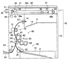
以下、本発明の実施の形態を、図を用いて説明する。図1は本発明の画像読み取り装置の実施形態に係る複写機の概略構成図である。本体ハウジング10は、上ハウジング11と下ハウジング12とを有し、上ハウジング11の上には押さえ蓋20が載置される。押さえ蓋20は紙面の奥側を開閉支点21として垂直面内で開閉自在に取り付けられている。
Hereinafter, embodiments of the present invention will be described with reference to the drawings. FIG. 1 is a schematic configuration diagram of a copying machine according to an embodiment of an image reading apparatus of the present invention. The
上ハウジング11には画像読み取り部30が内蔵されている。画像読み取り部30は、透明ガラス製のプラテン31、露光ランプ32、第1のミラー33、第2のミラー34、第3のミラー35、集光レンズ36およびイメージセンサ(例えばライン型のCCD)37を備える。露光ランプ32および第1のミラー33は読み取りユニット枠38aの内部に配置され、読み取りユニット38を構成する。読み取りユニット38は、ワイヤー39aとプーリー39bとプーリー39bに連結された図示しないモータからなる読み取りユニット駆動部39により図中左右方向に移動することができる。
An
プラテン31上に載置された図示しない原稿は、読み取りユニット駆動部39により移動する読み取りユニット38の露光ランプ32からの照射光により露光される。照射光は第1のミラー33、第2のミラー34、第3のミラー35および集光レンズ36を通じてCCD37に到達して光電変換処理を経て電気信号となるように読み取られる。
A document (not shown) placed on the
下ハウジング12の上部には排紙口14および胴内排紙トレイ15が設けられており、画像が形成された用紙Pが排出される。
A
また、下ハウジング12には、制御部40、給紙部50、画像形成部60および定着部70が内蔵されている。制御部40は複写機全体の動作を制御するものである。給紙部50は給紙カセット51、給紙ローラ52、手差し給紙トレイ53、給紙ローラ54および搬送ローラ対55からなる。給紙カセット51は、用紙Pを収容するものであり、下ハウジング12の下部に配設される。用紙Pはここから給紙ローラ52により1枚ずつ用紙搬送路56へ送り出され、搬送ローラ対55によって搬送される。また、手差し給紙トレイ53は下ハウジング12の左側面の下部に、開閉可能に備えられている。破線で示す閉じた状態から実線で示すように手で開いた手差し給紙トレイ53に置いた用紙Pを手で下ハウジング12の中に押し込んでいけば、給紙カセット51の用紙Pと同様に用紙Pは給紙ローラ54により1枚ずつ用紙搬送路56へ送り出され、搬送ローラ対55などによって搬送される。
The
次に画像形成部60について説明する。画像形成部60は、感光体ドラム61と、その周囲に配設された帯電器62、光走査ユニット63、現像器64、転写ローラ65、クリーニング器66とを備える。感光体ドラム61は図1において時計回りに回転し、まず帯電器62により感光体ドラム61の表面は均一に帯電される。次に、光走査ユニット63から感光体ドラム61の表面にレーザ光が照射されて、用紙Pに形成される画像の部分又は前記画像以外の部分に相当する電荷が消去され、感光体ドラム61の表面に静電潜像が形成される。そして現像器64によって、この静電潜像にトナーが供給され静電潜像が顕像化する。
Next, the
感光体ドラム61がさらに回転し、トナー画像が転写ローラ65と対向する位置に来たときに、それに合わせて、感光体ドラム61と転写ローラ65との間に用紙Pが搬送されてくる。このとき転写ローラ65に、トナーの帯電極性と逆極性の電圧が印加されることにより、感光体ドラム61上のトナー画像が用紙P上に転写される。感光体ドラム61上の転写されなかった残留トナーはクリーニング器66によって感光体ドラム61上から除去される。一方トナー画像が転写された用紙Pは定着ローラ71と加圧ローラ72とが圧接してなる定着部70に搬送され、ここでトナー画像は加熱・加圧されて用紙Pに定着する。その後用紙Pは排出ローラ対57により、排紙口14から胴内排紙トレイ15に排出される。
When the
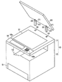
図2は本発明の実施形態に係る複写機の外観斜視図である。本発明の実施形態において、押さえ蓋20は上ハウジング11に着脱自在に取り付けられている。押さえ蓋20の開閉支点21は蝶番22によって脚部23が取り付けられており、上ハウジング11には脚部23を挿入できる脚部挿入口16および表示板18aとテンキーなどの操作ボタン18bを備えた操作パネル18が設けられている。ここで、押さえ蓋20は、押さえ蓋20と同様に上ハウジング11に着脱自在に取り付けられる自動原稿搬送装置であってもよい。
FIG. 2 is an external perspective view of the copying machine according to the embodiment of the present invention. In the embodiment of the present invention, the
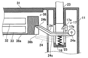
図3は読み取りユニット38と脚部挿入口16の近傍を図1の右方から見た部分断面図である。上ハウジング11にはロック部材24が、脚部挿入口16と交わるように配置され、支点24aを中心として回動するように設けられている。読み取りユニット枠38aにはロック部材24の先端24bと係合する係合部38bが設けられている。係合部38bは、ロック部材24が回動する際に先端24bがぶつからないように、先端24bのなす弧に合わせて曲線を描いている。
3 is a partial cross-sectional view of the vicinity of the
ロック部材24は、脚部挿入口16に脚部23が挿入されていない時は圧縮コイルばねなどからなる付勢手段25により上方に付勢され、実線で示す読み取りユニットロック態勢を保ち、先端24bが読み取りユニット枠38aに設けられた係合部38bに係合し、読み取りユニット38をロックする。また、脚部23が挿入されるとロック部材24のアーム部24cが脚部23に押されてロック部材24が破線で示すように下方に回動して読み取りユニットロック態勢を解除し、先端24bの係合部38bとの係合が外れて読み取りユニット38は移動可能な状態となる。
The
このように構成することにより、使用者が読み取りユニット38のロックについて意識しなくても、購入時の輸送の際は押さえ蓋20と本体ハウジング10とが別に梱包されている状態であるため、読み取りユニット38はロックされた状態となっており、輸送中に読み取りユニット38が動いて第1のミラー33または露光ランプ32の角度または位置がずれることがなくなる。その後、設置場所で開梱して押さえ蓋20を本体ハウジング10に取り付けて複写機を組み立てると、これも使用者が意識することなく、読み取りユニット38のロックは解除される。
With this configuration, even if the user is not conscious of the lock of the
通常、複写機において、主電源を入れた際に初期動作として読み取りユニット38に所定の動作をさせるが、固定部材を使用して読み取りユニット38を固定した場合に固定部材を外し忘れると、初期動作によって読み取りユニット38の図示しない駆動部に無理な負荷がかかって読み取りユニットが変形したり、図示しない駆動用のモータが脱調したりする可能性がある。しかし、押さえ蓋20を取り付けていればロックが解除されているため、初期動作による上述したような事故がなくなる。
Normally, in a copying machine, when the main power is turned on, the
脚部挿入口16の下方には脚部23が挿入されているかどうかを検知する検知手段17が設けられている。検知手段17はスイッチ本体17aとアクチュエータ17bで構成される。脚部23が挿入されていない時にはアクチュエータ17bが実線で示すように脚部挿入口16の内側に突出しているが、脚部23が挿入されるとアクチュエータ17bが脚部23に触れて破線で示すように脚部挿入口16の外側に押し出され、脚部23が挿入されていることを検知している状態となる。
Below the
検知手段17が実線で示すように脚部23が挿入されていないことを検知している時には制御部40は読み取りユニット38を駆動させない。また、操作パネルの表示部に、押さえ蓋20を取り付ける旨を表示する。一方、破線で示すように脚部23が挿入されていることを検知している時には必要に応じて読み取りユニット38を駆動する。
When the detecting
このように構成することにより、押さえ蓋20を取り付けない状態すなわち読み取りユニット38がロックされた状態で主電源を入れた場合に、上述した初期動作をさせないため、ロックされた読み取りユニット38を駆動しようとすることによる無用の事故を防ぐことができる。また、主電源が入っているので、表示板18aでの表示により使用者に押さえ蓋20の取り付けを喚起することができる。
With this configuration, when the main power supply is turned on in a state in which the
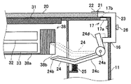
本発明の実施形態において、押さえ蓋20を本体ハウジング10に取り付ける方法は、上ハウジング11に設けられた脚部挿入口16に上方から垂直に脚部23を挿入するものに限られず、ロック部材を動作させることができるものであれば図4のように上ハウジング11の背面にねじ止めするようなものであっても構わない。図4において、押さえ蓋20の脚部23は、上ハウジング11の背面に設けられた脚部挿入口16から挿入され、ねじ26で固定される。このとき、ロック部材24のアーム部24dに接触してロック部材24を回動させ、読み取りユニット38のロックを解除する。
In the embodiment of the present invention, the method of attaching the
検知手段17を設ける位置は脚部挿入口16近傍に限られず、押さえ蓋20の構成部材が触れる位置であれば、図3のように上ハウジング11の上面の脚部23が触れる位置でも構わない。
The position where the detection means 17 is provided is not limited to the vicinity of the
検知手段17の代わりに、検知手段17と同じ場所に複写機全体への電力供給回路を開閉するスイッチを設けてもよい。このスイッチは、押さえ蓋20が本体ハウジング10に取り付けられている時は脚部23により閉状態となり、取り外されている時は開状態となるものである。この場合、押さえ蓋20を取り付けると図示しない主電源スイッチにより複写機への電力供給を操作することができるが、押さえ蓋20を取り付けずに主電源スイッチを入れても複写機には電力が供給されない。これにより、押さえ蓋20が取り付けられていない状態では上述した初期動作をさせないため、ロックされた読み取りユニット38を駆動しようとすることによる無用の事故を防ぐことができる。
Instead of the detection means 17, a switch for opening and closing the power supply circuit for the entire copying machine may be provided at the same place as the detection means 17. This switch is closed by the
本発明のロック機構は、画像読み取り装置に限られず、輸送時に複数の部材に分割し、いずれかの部材の内部に輸送時には固定したい可動部を有するものであれば利用することができる。 The locking mechanism of the present invention is not limited to an image reading device, and any locking mechanism can be used as long as it has a movable part that is divided into a plurality of members during transportation and that is desired to be fixed during transportation.
10 本体ハウジング
11 上ハウジング
12 下ハウジング
17 検知手段
20 押さえ蓋
21 開閉支点
23 脚部
24 ロック部材
30 画像読み取り部
31 透明ガラス製プラテン
38 読み取りユニット
DESCRIPTION OF
Claims (2)
前記押さえ蓋は脚部により前記本体に着脱自在に取り付けられるものであり、前記読み取りユニットにはその移動をロックするロック部材が組み合わせられるとともに、このロック部材は、前記押さえ蓋の脚部が本体に取り付けられていない時には付勢手段の付勢力により読み取りユニットロック態勢を保ち、前記脚部が本体に取り付けられた時には前記脚部に押されて前記付勢力に抗し読み取りユニットロック態勢を解除することを特徴とする画像読み取り装置。 A transparent glass platen for placing a document on the main body, a reading unit that is arranged below the platen, moves in the horizontal direction and reads an image of the document placed on the platen, and one end as an opening / closing fulcrum In an image reading apparatus comprising a pressing lid that opens and closes in a vertical plane and presses down a document placed on the platen when closed.
The pressing lid is detachably attached to the main body by a leg portion, and a locking member for locking the movement is combined with the reading unit, and the locking member includes a leg portion of the pressing lid on the main body. When not attached, the reading unit lock posture is maintained by the urging force of the urging means, and when the leg portion is attached to the main body, it is pushed by the leg portion to release the reading unit lock posture against the urging force. An image reading apparatus characterized by the above.
Priority Applications (1)
| Application Number | Priority Date | Filing Date | Title |
|---|---|---|---|
| JP2004209395A JP4265785B2 (en) | 2004-07-16 | 2004-07-16 | Image reading device |
Applications Claiming Priority (1)
| Application Number | Priority Date | Filing Date | Title |
|---|---|---|---|
| JP2004209395A JP4265785B2 (en) | 2004-07-16 | 2004-07-16 | Image reading device |
Publications (2)
| Publication Number | Publication Date |
|---|---|
| JP2006033419A JP2006033419A (en) | 2006-02-02 |
| JP4265785B2 true JP4265785B2 (en) | 2009-05-20 |
Family
ID=35899234
Family Applications (1)
| Application Number | Title | Priority Date | Filing Date |
|---|---|---|---|
| JP2004209395A Expired - Fee Related JP4265785B2 (en) | 2004-07-16 | 2004-07-16 | Image reading device |
Country Status (1)
| Country | Link |
|---|---|
| JP (1) | JP4265785B2 (en) |
Families Citing this family (2)
| Publication number | Priority date | Publication date | Assignee | Title |
|---|---|---|---|---|
| JP5197289B2 (en) | 2008-10-08 | 2013-05-15 | キヤノン株式会社 | Image reading apparatus and image reading and recording apparatus |
| JP6759671B2 (en) * | 2016-03-31 | 2020-09-23 | ブラザー工業株式会社 | Image forming device |
-
2004
- 2004-07-16 JP JP2004209395A patent/JP4265785B2/en not_active Expired - Fee Related
Also Published As
| Publication number | Publication date |
|---|---|
| JP2006033419A (en) | 2006-02-02 |
Similar Documents
| Publication | Publication Date | Title |
|---|---|---|
| US9075376B2 (en) | Automatic document feeder and image forming apparatus including the same | |
| KR930005903B1 (en) | Paper feeder with lifting tray | |
| US7894097B2 (en) | Image forming apparatus with controller to control operation based on open or closed state of upper portion of apparatus | |
| JP2020083547A (en) | Sheet feeding apparatus and image forming apparatus | |
| JP6045554B2 (en) | Image reading apparatus and image forming apparatus including image reading apparatus | |
| US20070223055A1 (en) | Multifunction apparatus | |
| JP6141231B2 (en) | Image forming apparatus | |
| JP4533443B2 (en) | Image forming apparatus | |
| JP4265785B2 (en) | Image reading device | |
| JPH1138714A (en) | Image forming device | |
| JP3467144B2 (en) | Automatic document feeder with binding document detection function | |
| JP3768848B2 (en) | Close assisting device, and automatic document feeder and image forming apparatus provided with the device | |
| JP5899157B2 (en) | Image forming apparatus | |
| CN100456150C (en) | Multifunctional product with a release mechanism to trigger the opening of the lid relative to the main body | |
| JP2009139673A (en) | Image forming apparatus | |
| JP4368766B2 (en) | Image forming apparatus | |
| US20070297831A1 (en) | Image-reading apparatus and image-forming apparatus | |
| JP5471216B2 (en) | Image forming apparatus | |
| JPH07271115A (en) | Automatic document feeder | |
| KR100717042B1 (en) | Image forming apparatus that can expand the space of delivery | |
| JP4932374B2 (en) | Image forming apparatus | |
| US9560226B2 (en) | Cover portion of image reading apparatus and image forming apparatus | |
| JP2002356002A (en) | Laser printer | |
| JPH11308385A (en) | Image reading device and image forming device | |
| JP2005049415A (en) | Image forming apparatus |
Legal Events
| Date | Code | Title | Description |
|---|---|---|---|
| A621 | Written request for application examination |
Free format text: JAPANESE INTERMEDIATE CODE: A621 Effective date: 20070627 |
|
| A131 | Notification of reasons for refusal |
Free format text: JAPANESE INTERMEDIATE CODE: A131 Effective date: 20081021 |
|
| A521 | Written amendment |
Free format text: JAPANESE INTERMEDIATE CODE: A523 Effective date: 20081216 |
|
| TRDD | Decision of grant or rejection written | ||
| A01 | Written decision to grant a patent or to grant a registration (utility model) |
Free format text: JAPANESE INTERMEDIATE CODE: A01 Effective date: 20090210 |
|
| A01 | Written decision to grant a patent or to grant a registration (utility model) |
Free format text: JAPANESE INTERMEDIATE CODE: A01 |
|
| A61 | First payment of annual fees (during grant procedure) |
Free format text: JAPANESE INTERMEDIATE CODE: A61 Effective date: 20090210 |
|
| R150 | Certificate of patent or registration of utility model |
Free format text: JAPANESE INTERMEDIATE CODE: R150 |
|
| FPAY | Renewal fee payment (event date is renewal date of database) |
Free format text: PAYMENT UNTIL: 20120227 Year of fee payment: 3 |
|
| LAPS | Cancellation because of no payment of annual fees |