JP4265784B2 - Game machine - Google Patents
Game machine Download PDFInfo
- Publication number
- JP4265784B2 JP4265784B2 JP2004177780A JP2004177780A JP4265784B2 JP 4265784 B2 JP4265784 B2 JP 4265784B2 JP 2004177780 A JP2004177780 A JP 2004177780A JP 2004177780 A JP2004177780 A JP 2004177780A JP 4265784 B2 JP4265784 B2 JP 4265784B2
- Authority
- JP
- Japan
- Prior art keywords
- light
- lens body
- condensing
- gaming machine
- disposed
- Prior art date
- Legal status (The legal status is an assumption and is not a legal conclusion. Google has not performed a legal analysis and makes no representation as to the accuracy of the status listed.)
- Expired - Fee Related
Links
- 239000000758 substrate Substances 0.000 claims description 28
- 238000009792 diffusion process Methods 0.000 claims description 16
- 238000003860 storage Methods 0.000 claims description 13
- 230000001678 irradiating effect Effects 0.000 claims description 6
- 230000003287 optical effect Effects 0.000 claims description 2
- 238000005034 decoration Methods 0.000 description 21
- 230000000694 effects Effects 0.000 description 12
- 238000004519 manufacturing process Methods 0.000 description 5
- 238000000034 method Methods 0.000 description 5
- 239000003086 colorant Substances 0.000 description 4
- 238000010276 construction Methods 0.000 description 4
- 230000002093 peripheral effect Effects 0.000 description 4
- 239000011347 resin Substances 0.000 description 4
- 229920005989 resin Polymers 0.000 description 4
- 238000012423 maintenance Methods 0.000 description 3
- 239000000853 adhesive Substances 0.000 description 2
- 230000001070 adhesive effect Effects 0.000 description 2
- 230000002708 enhancing effect Effects 0.000 description 2
- 230000004397 blinking Effects 0.000 description 1
- 238000004891 communication Methods 0.000 description 1
- 238000013461 design Methods 0.000 description 1
- 238000001514 detection method Methods 0.000 description 1
- 229910003460 diamond Inorganic materials 0.000 description 1
- 239000010432 diamond Substances 0.000 description 1
- 238000001035 drying Methods 0.000 description 1
- 239000011521 glass Substances 0.000 description 1
- 238000009434 installation Methods 0.000 description 1
- 239000000203 mixture Substances 0.000 description 1
- 238000012986 modification Methods 0.000 description 1
- 230000004048 modification Effects 0.000 description 1
- 239000003973 paint Substances 0.000 description 1
- 238000005192 partition Methods 0.000 description 1
- 230000000149 penetrating effect Effects 0.000 description 1
- 239000012466 permeate Substances 0.000 description 1
- 238000007788 roughening Methods 0.000 description 1
- 230000003746 surface roughness Effects 0.000 description 1
Images
Landscapes
- Pinball Game Machines (AREA)
Description
本発明は、発光による装飾演出を複雑にして遊技の興趣を高めたパチンコ遊技機等の遊技機に関する。 The present invention relates to a gaming machine such as a pachinko gaming machine in which the decoration effect by light emission is complicated to enhance the interest of the game.
従来の遊技機、例えばパチンコ遊技機において、所謂センターケース等の窓枠状前面構成部材に開設した開口部から変動表示ゲームが表示される画像表示領域を臨ませ、前面構成部材の上部には、装飾レンズ部材から光を透過する発光ユニットを備えたものが提案されている(例えば、特許文献1参照)。
そして、上記パチンコ遊技機は、表示領域で表示される変動表示ゲームの状態に応じて発光ユニットを発光させることで装飾演出を行えるように構成されている。
The pachinko gaming machine is configured to perform a decoration effect by causing the light emitting unit to emit light according to the state of the variable display game displayed in the display area.
しかしながら、上述したパチンコ遊技機では、発光により行う装飾演出を、発光する色や発光のタイミング、或いは発光態様(例えば点滅周期)のみに基づいて行うことしかできなかった。このため、さらに興趣性の高い演出を実現するために、発光方向を可変可能な発光ユニットを備えた遊技機が要望されている。ところが、窓枠内の限られたスペースに発光方向を可変可能な発光ユニットを配置することや、発光体への給電方法、或いは発光方向の可変構造を簡略化して組み付け性を向上させること等、様々な問題があった。 However, in the pachinko gaming machine described above, the decoration effect performed by light emission can only be performed based on the light emission color, the light emission timing, or the light emission mode (for example, the blinking cycle). For this reason, in order to realize a more interesting performance, there is a demand for a gaming machine equipped with a light emitting unit capable of changing the light emitting direction. However, arranging a light emitting unit capable of changing the light emission direction in a limited space in the window frame, improving the assembly by simplifying the power feeding method to the light emitter, or the variable structure of the light emission direction, etc. There were various problems.
そこで、本発明は、上記の事情に鑑みてなされたものであり、その目的は、簡単な構造で光の方向を変化させる装飾演出を実現して遊技の興趣を高めることができる遊技機を提供しようとするものである。 Accordingly, the present invention has been made in view of the above circumstances, and an object thereof is to provide a gaming machine capable of enhancing the fun of a game by realizing a decoration effect that changes the direction of light with a simple structure. It is something to try.
本発明は、上記目的を達成するために提案されたものであり、請求項1に記載のものは、画像表示領域が臨む開口部を開設した窓枠の上部に発光装置を備えた遊技機において、
前記発光装置は、
前端部を回動軸周りに上下回動可能とする状態で軸着された集光部と、
該集光部を上下回動駆動する駆動源と、
発光体を前記集光部の後端部に臨ませる状態で実装した発光基板と、
を備え、
前記集光部は、
前端に主レンズを形成すると共に、後端を開放した筒状のレンズ体と、
該レンズ体の後端を塞ぐと共に、前記発光体に対向し得る位置に配置される光拡散レンズ体と、
内部に前記レンズ体を収納して前方から前記主レンズを、後方から前記光拡散レンズ体をそれぞれ臨ませ、外部上端には前記回動軸が軸着される軸受部を設け、不透明な部材で成形された収納体と、
を具備し、
前記光拡散レンズ体は、透過する光を拡散するように構成され、
前記レンズ体は、前記光拡散レンズ体により後方から内部へ照射される光を拡散した状態で前方へ投光し、該投光した光を前記主レンズから前方へ向けて照射するように構成され、
前記駆動源を駆動して集光部の前端部を上下回動することで前記発光体から発光される光を、前記主レンズから前方へ向けて照射しながら上下方向へ動かすことを特徴とする遊技機である。
The present invention has been proposed in order to achieve the above object. According to the first aspect of the present invention, there is provided a gaming machine having a light emitting device on an upper portion of a window frame having an opening facing an image display area. ,
The light emitting device
A condensing part pivotally attached in a state in which the front end part can be turned up and down around the turning axis ;
A drive source for driving the condensing unit to rotate up and down;
A light-emitting substrate mounted with a light emitter facing the rear end of the light-collecting unit;
With
The condensing part is
A cylindrical lens body having a main lens at the front end and an open rear end;
A light diffusing lens body that closes the rear end of the lens body and is disposed at a position that can face the light emitter;
The main lens from the front to accommodate the lens body therein, respectively to face the light diffusing lens body from the rear, the outside upper end provided with a bearing portion where the rotating shaft is axially mounted, an opaque member Molded storage body,
Comprising
The light diffusing lens body is configured to diffuse the transmitted light;
Said lens body, projecting light and forward in a state that diffuses light emitted from the rear to the inside by the light diffusing lens body is configured so as to irradiate toward the front of the light-projecting optical from said main lens ,
The driving source is driven to move the front end of the light collecting unit up and down to move the light emitted from the light emitter up and down while irradiating the main lens forward from the main lens. It is a gaming machine.
請求項2に記載のものは、前記発光基板は、前記発光体と前記集光部との間であり、かつ、前記光拡散レンズ体に対向し得る位置に導光路を配し、
該導光路により前記発光体からの光を前記光拡散レンズ体へ導くことを特徴とする請求項1に記載の遊技機である。
According to a second aspect of the present invention, the light emitting substrate is disposed between the light emitter and the light collecting unit, and a light guide path is disposed at a position that can face the light diffusion lens body,
The gaming machine according to claim 1, wherein light from the light emitter is guided to the light diffusion lens body by the light guide path .
請求項3に記載のものは、前記集光部は、前記発光装置に取り付けられた常態で、前記光拡散レンズ体と前記発光基板とが平行となることを特徴とする請求項1または請求項2に記載の遊技機である。
そして、前記軸受部に回動軸を嵌入して前記集光部を横に並べて複数連結すると共に、複数の前記集光部の後端部を架設体によって固定することで集光機構を構成し、
前記発光装置は、
前記回動軸の両端部を支持して集光機構を上下回動可能に軸着する前側ケースと、
前記駆動源が配設されると共に、前記前側ケースの裏側を塞ぐ後側ケースと、
を備え、
前記前側ケースと前記後側ケースとの間に、前記発光基板を配設してもよい。
According to a third aspect of the present invention, the light diffusing lens body and the light emitting substrate are parallel to each other in the normal state where the light collecting unit is attached to the light emitting device. 2. The gaming machine according to 2.
Then, a rotating shaft is fitted into the bearing portion, the light collecting portions are arranged side by side and connected together, and a plurality of the light collecting portions are fixed by a construction body to constitute a light collecting mechanism. ,
The light emitting device
A front case that supports both ends of the rotating shaft and pivotally attaches the light collecting mechanism so as to be vertically rotatable;
The drive source is disposed, and a rear case that closes the back side of the front case,
With
The light emitting substrate may be disposed between the front case and the rear case.
本発明によれば、以下のような優れた効果を奏する。
請求項1に記載の発明によれば、集光部は、前端に主レンズを形成すると共に、後端を開放した筒状のレンズ体と、該レンズ体の後端を塞ぐと共に、前記発光体に対向し得る位置に配置される光拡散レンズ体と、内部に前記レンズ体を収納して前方から前記主レンズを、後方から前記光拡散レンズ体をそれぞれ臨ませ、外部上端には前記回動軸が軸着される軸受部を設け、不透明な部材で成形された収納体とを具備し、光拡散レンズ体は、透過する光を拡散するように構成され、レンズ体は、光拡散レンズ体により後方から内部へ照射される光を拡散した状態で前方へ投光し、該投光した光を主レンズから前方へ向けて照射するように構成され、駆動源を駆動して集光部の前端部を上下回動することで発光体から発光される光を、主レンズから前方へ向けて照射しながら上下方向へ動かすので、遊技状態や、画像表示領域の表示画像に応じて光を上下方向へ動かすことができる。このことから、発光色や発光態様(点滅等)による装飾演出に加えて、光の方向を変化させる装飾演出も行うことができ、遊技の興趣を高めることができる。
また、主レンズと光拡散レンズ体との間隔を一定に保つことができ、設計どおりの光の照射状態を維持することができる。したがって、遊技中の装飾演出を安定させて、遊技の興趣を維持することができる。
According to the present invention, the following excellent effects can be obtained.
According to the first aspect of the present invention, the condensing unit forms the main lens at the front end, closes the rear end of the cylindrical lens body with the rear end open, and the light emitter. A light diffusing lens body disposed at a position that can be opposed to the light source, and housing the lens body therein, facing the main lens from the front, and facing the light diffusing lens body from the rear, and turning the outer upper end to the rotation And a housing formed of an opaque member. The light diffusing lens body is configured to diffuse the transmitted light, and the lens body is a light diffusing lens body. The light emitted from the rear to the inside is projected forward in a diffused state, and the projected light is emitted forward from the main lens . the light emitted from the light emitter by the front end vertical rotation, or a main lens Since moving vertically while irradiating toward the front, and the game state, you can move the light in the vertical direction in accordance with the display image of the image display area. From this, in addition to the decoration effect by the light emission color and the light emission mode (flashing etc.), the decoration effect which changes the direction of light can also be performed and the interest of a game can be heightened.
In addition, the distance between the main lens and the light diffusing lens body can be kept constant, and the light irradiation state as designed can be maintained. Therefore, the decoration effect during the game can be stabilized and the interest of the game can be maintained.
請求項2に記載の発明によれば、発光基板は、発光体と集光部との間であり、かつ、光拡散レンズ体に対向し得る位置に導光路を配し、該導光路により発光体からの光を光拡散レンズ体へ導くので、発光体を集光部から離して設けても、発光体からの光を光拡散レンズ体まで導くことができる。したがって、集光部の配置の自由度を増すことができ、遊技内容に合わせて適切な位置に集光部を配置することができる。また、上下回動する集光部に発光体を衝突させる虞がなく、発光体が損傷する不都合を防ぐことができる。 According to the second aspect of the present invention, the light emitting substrate is disposed between the light emitter and the light condensing unit, and the light guide path is disposed at a position that can face the light diffusion lens body, and light is emitted by the light guide path. Since the light from the body is guided to the light diffusing lens body, the light from the luminescent body can be guided to the light diffusing lens body even if the light emitting body is provided away from the light condensing part. Therefore, the freedom degree of arrangement | positioning of a condensing part can be increased, and a condensing part can be arrange | positioned in a suitable position according to the game content. Moreover, there is no possibility of causing the light emitter to collide with the converging part that rotates up and down, and it is possible to prevent inconvenience that the light emitter is damaged.
請求項4に記載の発明によれば、軸受部に回動軸を嵌入して集光部を横に並べて複数連結すると共に、複数の集光部の後端部を架設体によって固定することで集光機構を構成し、発光装置は、回動軸の両端部を支持して集光機構を上下回動可能に軸着する前側ケースと、駆動源が配設されると共に、前側ケースの裏側を塞ぐ後側ケースと、を備え、前側ケースと後側ケースとの間に、発光基板を配設したので、上下回動する集光機構から発光体の配線を引き出す必要がない。したがって、発光体の配線処理が格段に容易になり、発光装置の製造効率を向上させることができる。さらに、集光機構が繰り返し上下回動することにより発光体の配線が断線する虞がなく、メンテナンス作業の軽減も図ることができる。 According to the fourth aspect of the present invention, the rotating shaft is fitted into the bearing portion, the light collecting portions are arranged side by side, and a plurality of light collecting portions are connected to each other, and the rear end portions of the plurality of light collecting portions are fixed by the installation body. The light-emitting device, which constitutes the light collecting mechanism, includes a front case that supports both ends of the rotating shaft and pivotally mounts the light collecting mechanism so that the light collecting mechanism can be turned up and down, a drive source, and the back side of the front case Since the light emitting substrate is disposed between the front case and the rear case, it is not necessary to draw out the wiring of the light emitter from the light collecting mechanism that rotates up and down. Therefore, the wiring process of the light emitter becomes much easier, and the manufacturing efficiency of the light emitting device can be improved. Furthermore, there is no possibility that the wiring of the light emitter is disconnected by repeatedly rotating the light collecting mechanism up and down, and the maintenance work can be reduced.
以下、代表的な遊技機であるパチンコ遊技機を例に挙げて本発明の実施の最良の形態を図面に基づき説明する。図1はパチンコ遊技機の遊技盤1の正面図である。 Hereinafter, the best mode for carrying out the present invention will be described with reference to the drawings, taking a pachinko gaming machine as a typical gaming machine as an example. FIG. 1 is a front view of a game board 1 of a pachinko gaming machine.
パチンコ遊技機の遊技盤1は、図1に示すように、表面にガイドレール等の区画部材2により区画された遊技領域3を形成し、該遊技領域3内の略中央には、可変表示装置の画像表示領域4を前方に臨ませたセンターケース5を配設し、該センターケース5の下方には、可変表示装置を始動するための始動入賞口6を、始動入賞口6の左右両側方には普通図柄始動ゲート7を、始動入賞口6および普通図柄始動ゲート7の下方には大入賞口8、普通図柄表示器9、普通図柄記憶表示器10を配置している。また、始動入賞口6、普通図柄始動ゲート7、大入賞口8等の入賞具やセンターケース5等の取付部分を除いた遊技領域3内に障害釘(図示せず)を植設してある。さらに、遊技盤1は、この他に、遊技球の流下方向を変える風車(図示せず)、発光により各種の装飾表示を行うランプ・LED11、及び入賞せずに流下した遊技球を回収するアウト口12を設けている。
As shown in FIG. 1, a game board 1 of a pachinko gaming machine has a
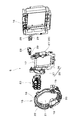
センターケース5は、図2および図3に示すように、遊技盤1の表面に取り付けられる取付ベース15(本発明の窓枠に相当)と、該取付ベース15の後方であって遊技盤1の裏側に取り付けられる制御ベース16と、該制御ベース16の前面に取り付けられる装飾ベース17とから概略構成されている。取付ベース15は、その上部に左右全幅に亘って庇状の鎧部18を前方に突設し、該鎧部18の左右端部から下方に縦長の側辺部19を延設し、左右の側辺部19の下端同士を接続する状態で底部20を設け、上記鎧部18、左右側辺部19、及び底部20に囲まれた凹室21の奥側に開口部22を開設している。また、開口部22の上縁には、遊技領域3の前方へ投光する発光装置23を備えている。なお、発光装置23については、後で詳細に説明する。
As shown in FIGS. 2 and 3, the
制御ベース16は、遊技盤1の後方へ向けて突出した額縁状の部材であり、内側の開口部分に可変表示装置(図示せず)を収納し、該可変表示装置の後側には遊技盤1の制御装置(例えば、演出制御装置)を備えている(図示せず)。なお、本実施形態の制御ベース16は、遊技球が流下可能な流路(図示せず)を設け、センターケース5の周辺の入賞具から入賞した遊技球を遊技盤1の裏側にて流下させる機能(所謂球寄せ機能)をも備えている。
The
装飾ベース17は、画像表示領域4の前方で動作する装飾ユニット25を遊技盤1に取り付けるための部材である。この装飾ベース17は、制御ベース16よりもひと回り小さい略額縁形状を呈しており、制御ベース16に収納可能な可変表示装置の画像表示領域4を囲む状態で制御ベース16の内側に取り付けられている。また、左右両側縁には、下方へ延設された多関節構造の腕部26と、該腕部26の先端に設けられた装飾部(本実施形態では、人差し指で物を指し示す状態の手を模した形状の装飾部)27とからなる装飾ユニット25をそれぞれ備えている。さらに、装飾ベース17の上部であって腕部26の基端部には、装飾部27を引き上げて画像表示領域4の前方を移動させるモータ等の装飾部駆動源28と、該装飾部駆動源28の駆動状態を検出する検出センサ29とを設けている。
The
次に、発光装置23について説明する。
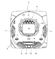
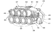
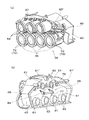
発光装置23は、図5および図6に示すように、サーチライトを模した形状の集光部35を複数(本実施形態では4つ)連設して成る集光機構36と、該集光機構36の上方に複数(本実施形態では3つ)設けられた円筒状の固定集光体37と、集光機構36及び固定集光体37の後方から光を照射する横長な発光源ボックス38とから構成されている。そして、図4に示すように、取付ベース15の後方から取り付けられ、取付ベース15の開口部22の上側から集光機構36および固定集光体37を前方へ臨ませている。
Next, the
As shown in FIGS. 5 and 6, the
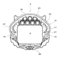
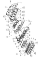
発光源ボックス38は、図6に示すように、後部を開放した箱状の前側ケース40と、該前側ケース40の後部(裏側)を塞ぐ後側ケース41と、前側ケース40と後側ケース41との間に配設され、発光体42を集光機構36および固定集光体37へ臨ませる状態で実装した発光基板43とから概略構成されている。前側ケース40は、前面に菱形状の装飾孔45を複数開設した外側ケース46と、該外側ケース46の内部に収納されて装飾孔45を後方から閉塞する内側ケース47とにより構成されている。また、当該前側ケース40の前面(すなわち外側ケース46の前面)の下側を上側よりも後方に配置して集光機構配置空間48を形成している。なお、この集光機構配置空間48は、集光機構36の後端部(すなわち集光部35の後端部)が当該前側ケース40に干渉しない程度の広さに形成する。そして、この集光機構配置空間48の左右両側であって、当該前側ケース40の前面の上側と下側との境界に位置する箇所には軸着部49を前方へ突設し、該軸着部49に、集光機構配置空間48内に配置した集光機構36を上下回動可能な状態で軸着している。さらに、集光機構配置空間48の上方に位置する前面には複数の固定集光体37を固定している。なお、集光機構36と前側ケース40との接続状態については、後で詳細に説明する。
As shown in FIG. 6, the light
後側ケース41は、前側ケース40の後方に配置される蓋部材であり、当該後側ケース41の内面(前面)には、図6に示すように、集光機構36を上下回動駆動する集光機構駆動ソレノイド51(本発明における駆動源に相当)を取り付けている。この集光機構駆動ソレノイド51は、出力軸である駆動ロッド(プランジャ)52を下方へ向けた状態で配設され、後述する集光機構36との接続部分を発光源ボックス38の内側に配置するように構成されている。したがって、パチンコ遊技機のメンテナンス時に作業員の手などが当たって誤って集光機構駆動ソレノイド51と集光機構36との接続が外れてしまう不都合を防ぐことができる。また、後側ケース41は、上端部から縦長の切欠部53を開設し、この切欠部53から集光機構駆動ソレノイド51の後部を突出させている。したがって、発光源ボックス38の奥行きを、集光機構駆動ソレノイド51が内部に収納される程の厚さで形成する必要がない。このことから、限られた取付ベース15内の空間、具体的には奥行きの空間において発光源ボックス38が占める部分を低く抑えて有効利用可能な空き空間を確保することができ、パチンコ遊技機の設計の自由度を増すことができる。
The
発光基板43は、図6に示すように、発光源ボックス38内の上側に収納される上側発光基板(固定集光体用発光基板)55と、発光源ボックス38の下側に収納される下側発光基板(集光機構用発光基板)56とに分割構成されている。上側発光基板55は、前側ケース40の前面裏側(詳しくは、内側ケース47の前面裏側)に取り付けられ、当該上側発光基板55の表面に実装した複数の発光体42を、固定集光体37の後端部に対向する部位に配設している。なお、本実施形態では、1つの固定集光体37に対向する位置毎に複数(本実施形態では4つ)の発光体42からなる発光体群57を配置するとともに、各発光体群57の左右両側方や上方にも単体の発光体42を配置している。
As shown in FIG. 6, the
また、下側発光基板56は、後側ケース41の内面(前面)に取り付けられ、当該下側発光基板56の表面に実装した複数の発光体42を、上下回動可能な集光部35の後端部に対向し得る部位に配設している。なお、本実施形態では、1つの集光部35に対応する位置毎に複数(本実施形態では4つ)の発光体42からなる発光体群58を配置するとともに、各発光体群58の上方および下方にも単体の発光体42を配置している。また、下側発光基板56の発光体群58は、発光色の異なる発光体42で構成されている。すなわち、下側発光基板56は、集光部35の後端部に対向し得る部位に発光色の異なる発光体42を複数実装している。
Further, the lower
そして、発光源ボックス38は、前側ケース40の前面のうち固定集光体37が配置される箇所、および集光機構36の集光部35の後端部が対向する箇所に、円状の導光孔60を横並びに開設して発光基板43上の発光体42を前方、すなわち固定集光体37および集光部35へ臨ませている(図6および図7(a)参照)。また、各導光孔60の縁部から後方へ円管状の導光壁61を延出し、該導光壁61により導光路62を区画形成して発光体42からの光を固定集光体37および集光部35へ導くように構成されている(図7(b)および(c)参照)。このように発光体42と集光部35との間、また発光体42と固定集光体37との間に設けられた導光路62は、発光体42が固定集光体37および集光部35から離れていても発光体42からの光を発光源ボックス38の内部に広く拡散させることなく、固定集光体37および集光部35へ導くことができる。したがって、集光部35および固定集光体37から投光される光の強さが弱くなる不都合を抑えることができる。なお、本実施形態では、固定集光体37に対向する箇所の周辺にも導光孔60′および導光壁61′を備えて、上側発光基板55上の発光体群57の周辺に設けられた単体の発光体42からの光も発光源ボックス38の前方へ投光できるように構成されている。
The light emitting
次に、発光源ボックス38に取り付けられる固定集光体37および集光機構36について説明する。
固定集光体37は、発光源ボックス38内の発光体42からの光を前方の一定方向へ照射するためのものであり、前端を凸レンズ(集光レンズ)64で閉塞するとともに後端を開放した横向きの筒状部材で形成されている。この固定集光体37は、後端を前側ケース40の導光孔60に重ねる状態で止着部材(図示せず)により止着されて当該固定集光体37の内部と導光路62とを連通し、発光体42からの光が導光路62を通じて凸レンズ64に達し、該凸レンズ64から前方へ投光するように構成されている。なお、外周面に不透明処理(例えば、不透明なカバーを取り付けたり、あるいは不透明塗料を塗装したりする処理)を施せば、固定集光体37は、凸レンズ64以外の場所から光を透過することがないので好適である。また、固定集光体37の後端を透光可能な部材(例えば透明樹脂製の光拡散レンズ板)で閉塞してもよい。
Next, the fixed condensing
The fixed condensing
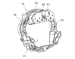
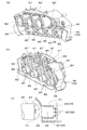
集光機構36は、発光源ボックス38内の発光体42からの光を前方へ照射しながら上下に動かすためのものであり、図8に示すように、複数の集光部35と、該集光部35を連結する回動軸66および架設体67と、当該集光機構36と集光機構駆動ソレノイド51とを連結するリンク部68とを備えている。
The
集光部35は、横向き円筒状のレンズ体70と、該レンズ体70の後端を塞ぐ光拡散レンズ体71と、内部にレンズ体70および光拡散レンズ体71を収納する収納体72とを具備している。レンズ体70は、前端に凸状の主レンズ(集光レンズ)73を形成すると共に後端を開放して、後方から内部へ照射される光を前方へ投光するように構成されている。光拡散レンズ体71は、薄い円板形状のレンズ部材であり、透過する光を拡散する構成、例えば、表面粗さを粗くして磨りガラス状に仕上げたり、あるいは、小さな四角錐状の突起(所謂ダイヤモンドカット)を表面に複数施したりしている。なお、レンズ体70および光拡散レンズ体71は、発光体42の発色をそのまま投光するために無色透明な部材(例えば、無色透明樹脂)により成形されているが、有色透明な部材や半透明の部材で成形してもよい。
The condensing
収納体72は、レンズ体70および光拡散レンズ体71よりもひと回り大きな円筒状の部材であり、前側の開放開口からレンズ体70の主レンズ73を、後側の開放開口から光拡散レンズ体71をそれぞれ臨ませている。また、不透明な部材で成形されてレンズ体70内を通過する光が集光部35の外周面から投光されることを防ぐように構成されている。さらに、外周部のうち上端には、回動軸66を嵌入する軸受部74を設け、上半部には略倒コ字状のブラケットを模した装飾部材75を外周に沿う状態で取り付けている。
The
そして、集光機構36は、複数の集光部35のうち何れかの軸受部74を後方に延設して、集光機構駆動ソレノイド51に接続するリンク部68を設けている。本実施形態では、中央2つの集光部35の軸受部74を後方に延設してリンクアーム76を形成し、両リンクアーム76の先端部の間にリンクロッド77を掛け渡してリンク部68を構成している。
The
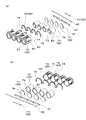
このような構成を備えた集光機構36を組み立てるには、まず、光拡散レンズ体71をレンズ体70の後端部に取り付ける。このとき、光拡散レンズ体71の縁部に形成した切欠部78をレンズ体70の後端縁から突出した位置決めピン79に嵌合して光拡散レンズ体71の位置決めを行う。光拡散レンズ体71を取り付けたならば、レンズ体70を、主レンズ73を前、光拡散レンズ体71を後に配置した姿勢で収納体72の後端部から挿入する。すると、レンズ体70の外周部前側に形成した切欠部80が収納体72の内周面に突設した位置決め突起81に嵌合し、主レンズ73が収納体72の前側開口と略同一面上に配置される状態で、レンズ体70と収納体72との位置が決まる。このようにして、レンズ体70、光拡散レンズ体71および収納体72の3つの部材をそれぞれ位置決めして、集光部35を複数仮組みする。仮組みされた集光部35は、主レンズ73と光拡散レンズ体71との間隔を一定に保つことができ、設計どおりの光の照射状態を維持することができる。したがって、遊技中の装飾演出を安定させて、遊技の興趣を維持することができる。
In order to assemble the
次に、仮組みされた各集光部35を、主レンズ73側の端部を揃えた状態で横に並べ、各軸受部74に回動軸66を嵌入して集光部35を連結する。また、各集光部35の後端部には、平板状の長尺な架設体67を、各集光部35の収納体72に形成された切欠溝82に嵌合するとともに収納体72の左右両側に突設した止着部83にビス等の止着部材(図示せず)で固定する。したがって、各集光部35は、他の集光部35から独立して回動軸66周りに回動してしまうことがない。また、各集光部35に固定された架設体67は、収納体72内の光拡散レンズ体71の後面に当接するので、レンズ体70及び光拡散レンズ体71が収納体72から脱落することを防ぐことができる。このように、集光機構36は、接着剤を一切使用せずに組み立てることができる。したがって、集光機構36の製造において接着剤の乾燥時間を見込む必要がなく、製造効率の向上を図ることができる。なお、架設体67は透明な部材により成形されているので、発光体42からの光が主レンズ73に到達するまでの間に遮られることがない。
Next, the temporarily assembled
そして、集光機構36を発光源ボックス38に組み付けるには、図9に示すように、リンクアーム76を前側ケース40のスリット84に貫通するとともに回動軸66を軸着部49に軸着して、集光機構36を集光機構配置空間48に配置する。集光機構36を配置したならば、前側ケース40に貫通したリンクアーム76の先端部にリンクロッド77を取り付け、前側ケース40と後側ケース41との間に発光基板43を配置し、集光機構駆動ソレノイド51を取り付けた後側ケース41を前側ケース40の後部に取り付ける。すると、各集光部35の後端部、すなわち光拡散レンズ体71が導光路62および下側発光基板56上の発光体群57に対向し得る位置に配置される。また、集光機構36のリンク部68のリンクロッド77が集光機構駆動ソレノイド51の駆動ロッド52に、接続部材85を介して接続される。
Then, in order to assemble the
このように集光機構36と発光源ボックス38とを接続した発光装置23は、集光機構駆動ソレノイド51を駆動して駆動ロッド52を上下動すると、集光機構36の先端(すなわち主レンズ73)を回動軸66周りに上下回動することができる。そして、発光体42を点灯状態にすれば、発光体42から発光される光を、主レンズ73から前方へ向けて照射しながら上下方向へ動かすことができる。したがって、遊技状態や、画像表示領域4の表示画像に応じて光を上下方向へ動かすことができる。このことから、発光色や発光態様(点滅等)による装飾演出に加えて、光の方向を変化させる装飾演出も行うことができ、遊技の興趣を高めることができる。
When the
また、発光体42を集光機構36ではなく、前側ケース40と後側ケース41との間、すなわち発光源ボックス38内に配設しているので、上下回動する集光機構36から発光体42の配線を引き出す必要がない。したがって、発光体42の配線処理が格段に容易になり、発光装置23の製造効率を向上させることができる。さらに、集光機構36が繰り返し上下回動することにより発光体42の配線が断線する虞がなく、メンテナンス作業の軽減も図ることができる。
Further, since the
そして、発光体42からの光は、導光路62により光拡散レンズ体71へ導かれるので、発光体42を集光部35から離して設けても、発光体42からの光を光拡散レンズ体71まで導くことができる。したがって、集光機構36の配置の自由度を増すことができ、遊技内容に合わせて適切な位置に集光機構36を配置することができる。また、上下回動する集光部35に発光体42を衝突させる虞がなく、発光体42が損傷する不都合を防ぐことができる。
The light from the
さらに、集光機構36は、下側発光基板56から発光された複数色の光を、光拡散レンズ体71により拡散して混色することができる。したがって、発光体群58のいずれの発光体42の発光色とは異なった色の発光を、色ムラを生じ難い状態で集光部35から照射することができ、遊技に伴う装飾演出を華やかに行うことができる。また、発光体群58のうち、同色の発光体42のみを点灯し、他色の発光体42を消灯すれば、混色しない状態の光、すなわち発光体42自体から発する色の光を集光機構36の集光部35から照射することができる。したがって、発光体42の発光の組み合わせを遊技の進行内容に基づいて選択して、一層華やかな遊技演出を行うことができ、遊技の興趣を高めることができる。
Further, the
なお、前側ケース40が透光可能な部材(例えば、透明樹脂製または半透明樹脂製)である場合には、発光基板43は、導光路62の後方に位置する部分以外にも発光体42を実装して発光源ボックス38の下面や前面全体に亘って光を発するようにすれば、パチンコ遊技機のセンターケース5の装飾性を一層向上させることができて好適である。
When the
また、上記実施形態では、発光装置23をセンターケース5に備えたが、本発明はこれに限定されない。例えば、センターケース5とは別に画像表示領域が臨む開口部を開設した窓枠を遊技領域3に備え、この窓枠の上部に発光装置を備えてもよい。
Moreover, in the said embodiment, although the light-emitting
前記した実施の形態は全ての点で例示であって制限的なものではないと考えられるべきである。本発明は、上記した説明に限らず特許請求の範囲によって示され、特許請求の範囲と均等の意味及び範囲内での全ての変更が含まれるものである。 The above-described embodiments are examples in all respects and should be considered not restrictive. The present invention is not limited to the above description, but is defined by the scope of the claims, and includes all modifications within the scope and meaning equivalent to the scope of the claims.
1 遊技盤
3 遊技領域
5 センターケース
15 取付ベース
16 制御ベース
17 装飾ベース
22 開口部
23 発光装置
25 装飾ユニット
35 集光部
36 集光機構
37 固定集光体
38 発光源ボックス
40 前側ケース
41 後側ケース
42 発光体
43 発光基板
48 集光機構配置空間
49 軸着部
51 集光機構駆動ソレノイド
52 駆動ロッド
55 上側発光基板
56 下側発光基板
57 発光体群
58 発光体群
60 導光孔
61 導光壁
62 導光路
64 凸レンズ
66 回動軸
67 架設体
68 リンク部
70 レンズ体
71 光拡散レンズ体
72 収納体
73 主レンズ
74 軸受部
75 装飾部材
76 リンクアーム
77 リンクロッド
DESCRIPTION OF SYMBOLS 1
Claims (4)
前記発光装置は、
前端部を回動軸周りに上下回動可能とする状態で軸着された集光部と、
該集光部を上下回動駆動する駆動源と、
発光体を前記集光部の後端部に臨ませる状態で実装した発光基板と、
を備え、
前記集光部は、
前端に主レンズを形成すると共に、後端を開放した筒状のレンズ体と、
該レンズ体の後端を塞ぐと共に、前記発光体に対向し得る位置に配置される光拡散レンズ体と、
内部に前記レンズ体を収納して前方から前記主レンズを、後方から前記光拡散レンズ体をそれぞれ臨ませ、外部上端には前記回動軸が軸着される軸受部を設け、不透明な部材で成形された収納体と、
を具備し、
前記光拡散レンズ体は、透過する光を拡散するように構成され、
前記レンズ体は、前記光拡散レンズ体により後方から内部へ照射される光を拡散した状態で前方へ投光し、該投光した光を前記主レンズから前方へ向けて照射するように構成され、
前記駆動源を駆動して集光部の前端部を上下回動することで前記発光体から発光される光を、前記主レンズから前方へ向けて照射しながら上下方向へ動かすことを特徴とする遊技機。 In a gaming machine equipped with a light emitting device on top of a window frame that has opened an opening facing the image display area,
The light emitting device
A condensing part pivotally attached in a state in which the front end part can be turned up and down around the turning axis ;
A drive source for driving the condensing unit to rotate up and down;
A light-emitting substrate mounted with a light emitter facing the rear end of the light-collecting unit;
With
The condensing part is
A cylindrical lens body having a main lens at the front end and an open rear end;
A light diffusing lens body that closes the rear end of the lens body and is disposed at a position that can face the light emitter;
The main lens from the front to accommodate the lens body therein, respectively to face the light diffusing lens body from the rear, the outside upper end provided with a bearing portion where the rotating shaft is axially mounted, an opaque member Molded storage body,
Comprising
The light diffusing lens body is configured to diffuse the transmitted light;
Said lens body, projecting light and forward in a state that diffuses light emitted from the rear to the inside by the light diffusing lens body is configured so as to irradiate toward the front of the light-projecting optical from said main lens ,
The driving source is driven to move the front end of the light collecting unit up and down to move the light emitted from the light emitter up and down while irradiating the main lens forward from the main lens. Gaming machine.
該導光路により前記発光体からの光を前記光拡散レンズ体へ導くことを特徴とする請求項1に記載の遊技機。 The light-emitting substrate is disposed between the light-emitting body and the light collecting unit, and a light guide path is disposed at a position that can face the light diffusion lens body,
The gaming machine according to claim 1, wherein light from the light emitter is guided to the light diffusion lens body by the light guide path.
前記発光装置は、
前記回動軸の両端部を支持して集光機構を上下回動可能に軸着する前側ケースと、
前記駆動源が配設されると共に、前記前側ケースの裏側を塞ぐ後側ケースと、
を備え、
前記前側ケースと前記後側ケースとの間に、前記発光基板を配設したことを特徴とする請求項1から請求項3の何れかに記載の遊技機。 With a plurality of connecting side by side the condenser part and fitted into the pivot shaft lying on the bearing portion, configures the light collecting mechanism by fixing the bridging member a rear end portion of the plurality of the condenser part,
The light emitting device
A front case that supports both ends of the rotating shaft and pivotally attaches the light collecting mechanism so as to be vertically rotatable;
The drive source is disposed, and a rear case that closes the back side of the front case,
With
The gaming machine according to any one of claims 1 to 3, wherein the light-emitting substrate is disposed between the front case and the rear case.
Priority Applications (1)
| Application Number | Priority Date | Filing Date | Title |
|---|---|---|---|
| JP2004177780A JP4265784B2 (en) | 2004-06-16 | 2004-06-16 | Game machine |
Applications Claiming Priority (1)
| Application Number | Priority Date | Filing Date | Title |
|---|---|---|---|
| JP2004177780A JP4265784B2 (en) | 2004-06-16 | 2004-06-16 | Game machine |
Publications (2)
| Publication Number | Publication Date |
|---|---|
| JP2006000251A JP2006000251A (en) | 2006-01-05 |
| JP4265784B2 true JP4265784B2 (en) | 2009-05-20 |
Family
ID=35769156
Family Applications (1)
| Application Number | Title | Priority Date | Filing Date |
|---|---|---|---|
| JP2004177780A Expired - Fee Related JP4265784B2 (en) | 2004-06-16 | 2004-06-16 | Game machine |
Country Status (1)
| Country | Link |
|---|---|
| JP (1) | JP4265784B2 (en) |
Families Citing this family (12)
| Publication number | Priority date | Publication date | Assignee | Title |
|---|---|---|---|---|
| JP4986492B2 (en) * | 2006-04-05 | 2012-07-25 | 京楽産業.株式会社 | Movable direction device for gaming machine |
| JP4560527B2 (en) * | 2007-04-16 | 2010-10-13 | 京楽産業.株式会社 | Game machine |
| JP2008307197A (en) * | 2007-06-14 | 2008-12-25 | Nippon Pachinko Buhin Kk | Game machine |
| JP4630322B2 (en) * | 2007-10-05 | 2011-02-09 | 株式会社藤商事 | Game machine |
| JP5213658B2 (en) * | 2008-11-20 | 2013-06-19 | 株式会社ニューギン | Game machine |
| JP5398277B2 (en) * | 2009-01-16 | 2014-01-29 | 株式会社ニューギン | Game machine |
| JP5398320B2 (en) * | 2009-03-27 | 2014-01-29 | 株式会社ニューギン | Game machine |
| JP5520324B2 (en) * | 2012-01-13 | 2014-06-11 | 株式会社藤商事 | Game machine |
| JP5520323B2 (en) * | 2012-01-13 | 2014-06-11 | 株式会社藤商事 | Game machine |
| JP2013255591A (en) * | 2012-06-11 | 2013-12-26 | Trust:Kk | Transparent plate unit of game machine frame |
| JP6008909B2 (en) * | 2014-07-22 | 2016-10-19 | 株式会社大一商会 | Game machine |
| JP6008910B2 (en) * | 2014-07-22 | 2016-10-19 | 株式会社大一商会 | Game machine |
-
2004
- 2004-06-16 JP JP2004177780A patent/JP4265784B2/en not_active Expired - Fee Related
Also Published As
| Publication number | Publication date |
|---|---|
| JP2006000251A (en) | 2006-01-05 |
Similar Documents
| Publication | Publication Date | Title |
|---|---|---|
| JP4012476B2 (en) | Bullet ball machine | |
| JP4265784B2 (en) | Game machine | |
| JP6181106B2 (en) | Game machine | |
| JP4749436B2 (en) | Lighting device, game board, and pachinko machine | |
| JP5039435B2 (en) | Game machine | |
| JP5247489B2 (en) | Game machine | |
| JP5252440B2 (en) | Game machine | |
| JP5388591B2 (en) | Game machine | |
| JP5588719B2 (en) | Game machine | |
| JP2012055473A (en) | Illumination unit, game board unit, and pachinko game machine | |
| JP5427004B2 (en) | Game machine | |
| JP2011104292A (en) | Game machine | |
| JP5252438B2 (en) | Game machine | |
| JP5550178B2 (en) | Game machine | |
| JP5024092B2 (en) | Pachinko machine | |
| JP5252439B2 (en) | Game machine | |
| JP5398277B2 (en) | Game machine | |
| JP4248522B2 (en) | Game machine | |
| JP2012038590A (en) | Rotating light | |
| JP5388596B2 (en) | Game machine | |
| JP5334811B2 (en) | Game machine | |
| JP5247490B2 (en) | Game machine | |
| JP5252436B2 (en) | Game machine | |
| JP5388595B2 (en) | Game machine | |
| JP5388593B2 (en) | Game machine |
Legal Events
| Date | Code | Title | Description |
|---|---|---|---|
| A977 | Report on retrieval |
Free format text: JAPANESE INTERMEDIATE CODE: A971007 Effective date: 20080229 |
|
| A131 | Notification of reasons for refusal |
Free format text: JAPANESE INTERMEDIATE CODE: A131 Effective date: 20080318 |
|
| A521 | Written amendment |
Free format text: JAPANESE INTERMEDIATE CODE: A523 Effective date: 20080513 |
|
| A131 | Notification of reasons for refusal |
Free format text: JAPANESE INTERMEDIATE CODE: A131 Effective date: 20080826 |
|
| A521 | Written amendment |
Free format text: JAPANESE INTERMEDIATE CODE: A523 Effective date: 20081022 |
|
| TRDD | Decision of grant or rejection written | ||
| A01 | Written decision to grant a patent or to grant a registration (utility model) |
Free format text: JAPANESE INTERMEDIATE CODE: A01 Effective date: 20090210 |
|
| A01 | Written decision to grant a patent or to grant a registration (utility model) |
Free format text: JAPANESE INTERMEDIATE CODE: A01 |
|
| A61 | First payment of annual fees (during grant procedure) |
Free format text: JAPANESE INTERMEDIATE CODE: A61 Effective date: 20090210 |
|
| R150 | Certificate of patent or registration of utility model |
Ref document number: 4265784 Country of ref document: JP Free format text: JAPANESE INTERMEDIATE CODE: R150 Free format text: JAPANESE INTERMEDIATE CODE: R150 |
|
| FPAY | Renewal fee payment (event date is renewal date of database) |
Free format text: PAYMENT UNTIL: 20120227 Year of fee payment: 3 |
|
| FPAY | Renewal fee payment (event date is renewal date of database) |
Free format text: PAYMENT UNTIL: 20120227 Year of fee payment: 3 |
|
| FPAY | Renewal fee payment (event date is renewal date of database) |
Free format text: PAYMENT UNTIL: 20120227 Year of fee payment: 3 |
|
| FPAY | Renewal fee payment (event date is renewal date of database) |
Free format text: PAYMENT UNTIL: 20120227 Year of fee payment: 3 |
|
| FPAY | Renewal fee payment (event date is renewal date of database) |
Free format text: PAYMENT UNTIL: 20130227 Year of fee payment: 4 |
|
| R250 | Receipt of annual fees |
Free format text: JAPANESE INTERMEDIATE CODE: R250 |
|
| FPAY | Renewal fee payment (event date is renewal date of database) |
Free format text: PAYMENT UNTIL: 20130227 Year of fee payment: 4 |
|
| FPAY | Renewal fee payment (event date is renewal date of database) |
Free format text: PAYMENT UNTIL: 20130227 Year of fee payment: 4 |
|
| FPAY | Renewal fee payment (event date is renewal date of database) |
Free format text: PAYMENT UNTIL: 20130227 Year of fee payment: 4 |
|
| FPAY | Renewal fee payment (event date is renewal date of database) |
Free format text: PAYMENT UNTIL: 20140227 Year of fee payment: 5 |
|
| R250 | Receipt of annual fees |
Free format text: JAPANESE INTERMEDIATE CODE: R250 |
|
| R250 | Receipt of annual fees |
Free format text: JAPANESE INTERMEDIATE CODE: R250 |
|
| R250 | Receipt of annual fees |
Free format text: JAPANESE INTERMEDIATE CODE: R250 |
|
| R250 | Receipt of annual fees |
Free format text: JAPANESE INTERMEDIATE CODE: R250 |
|
| R250 | Receipt of annual fees |
Free format text: JAPANESE INTERMEDIATE CODE: R250 |
|
| R250 | Receipt of annual fees |
Free format text: JAPANESE INTERMEDIATE CODE: R250 |
|
| LAPS | Cancellation because of no payment of annual fees |