JP4265782B2 - Thin film forming method and apparatus - Google Patents
Thin film forming method and apparatus Download PDFInfo
- Publication number
- JP4265782B2 JP4265782B2 JP2004170665A JP2004170665A JP4265782B2 JP 4265782 B2 JP4265782 B2 JP 4265782B2 JP 2004170665 A JP2004170665 A JP 2004170665A JP 2004170665 A JP2004170665 A JP 2004170665A JP 4265782 B2 JP4265782 B2 JP 4265782B2
- Authority
- JP
- Japan
- Prior art keywords
- thin film
- sputtering
- target
- atoms
- sub
- Prior art date
- Legal status (The legal status is an assumption and is not a legal conclusion. Google has not performed a legal analysis and makes no representation as to the accuracy of the status listed.)
- Expired - Fee Related
Links
Images
Landscapes
- Physical Vapour Deposition (AREA)
Description
本発明は、強誘電体メモリ、光変調器、波長変換デバイス、SAWデバイスなどにおいて使用されるLiNbO3(ニオブ酸リチウム)やLiTaO3(タンタル酸リチウム)のバルク単結晶に代わって使用可能な高品質な結晶薄膜をスパッタリングにより基板表面に成膜する薄膜形成方法および装置に関するものである。 The present invention can be used in place of a bulk single crystal of LiNbO 3 (lithium niobate) or LiTaO 3 (lithium tantalate) used in ferroelectric memories, optical modulators, wavelength conversion devices, SAW devices and the like. The present invention relates to a thin film forming method and apparatus for forming a quality crystal thin film on a substrate surface by sputtering.
欠陥の少ないLiNbO3やLiTaO3などの結晶薄膜を異種材料の基板表面に形成できると、リーク電流が少なく、分極特性に優れた強誘電体メモリや微小導波路型光デバイスヘの応用が開けることになる。 If crystal thin films such as LiNbO 3 and LiTaO 3 with few defects can be formed on the substrate surface of dissimilar materials, there will be less application of leakage current and excellent polarization characteristics to ferroelectric memories and micro-waveguide optical devices. Become.
従来、結晶薄膜をECR(電子サイクロトロン共鳴)スパッタリングにより作製するには、1個のターゲットを使用するのが通常であった。例えば、LiNbO3のターゲットは、一般的に、Li2CO3粉末とNb2O5粉末をある割合で混合して、アルコール系樹脂のバインダーを添加後、成形、焼結を経て作製される。このターゲットからスパッタリングされる粒子を、対向する基板表面に付着させてLiNbO3薄膜を成膜する。一方、LiTaO3の場合は、Nb2O5粉末の代わりにTa2O5粉末を用い、上記と同様の過程を経て、LiTaO3薄膜を成膜する。ECRプラズマを生成するために、アルゴンガスを導入し、酸素原子の量を調整するために、酸素ガスを導入する。成膜条件として制御可能なパラメータとしては、一般的に酸素分圧と基板温度がある。 Conventionally, in order to produce a crystalline thin film by ECR (electron cyclotron resonance) sputtering, it has been usual to use one target. For example, a LiNbO 3 target is generally produced by mixing Li 2 CO 3 powder and Nb 2 O 5 powder in a certain ratio, adding an alcohol resin binder, and then molding and sintering. A LiNbO 3 thin film is formed by attaching particles sputtered from the target to the opposing substrate surface. On the other hand, in the case of LiTaO 3 , a Ta 2 O 5 powder is used instead of the Nb 2 O 5 powder, and a LiTaO 3 thin film is formed through the same process as described above. In order to generate ECR plasma, argon gas is introduced, and oxygen gas is introduced to adjust the amount of oxygen atoms. Parameters that can be controlled as film forming conditions generally include an oxygen partial pressure and a substrate temperature.
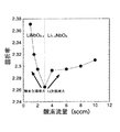
このようなECRスパッタリングにより成膜されるLiNbO3薄膜の組成は、酸素流量に敏感に依存する。図2は、あるスパッタリング装置で成膜したLiNbO3結晶薄膜の屈折率を、波長633nmのエリプソメトリーにより測定し、成膜時の酸素流量に対してプロットしたものである。 The composition of the LiNbO 3 thin film formed by such ECR sputtering sensitively depends on the oxygen flow rate. FIG. 2 is a graph in which the refractive index of a LiNbO 3 crystal thin film formed by a sputtering apparatus is measured by ellipsometry at a wavelength of 633 nm and plotted against the oxygen flow rate during film formation.
この材料では、膜中のLi原子や酸素原子の欠陥が増加するほど屈折率が大きくなる。酸素流量を低くすると薄膜中に取り込まれる酸素原子の数が減少し、酸素空孔を多く含む膜LiNbO3-Xが形成される。一方、酸素流量を高くすると、ターゲット上及び基板表面でLi原子と酸素原子が結びついてLi2O分子の形で脱離する反応が促進され、その結果Li空孔を含む膜Li1-XNbO3が形成される。 In this material, the refractive index increases as the defects of Li atoms and oxygen atoms in the film increase. When the oxygen flow rate is lowered, the number of oxygen atoms taken into the thin film is reduced, and a film LiNbO 3-X containing many oxygen vacancies is formed. On the other hand, when the oxygen flow rate is increased, a reaction in which Li atoms and oxygen atoms are combined and desorbed in the form of Li 2 O molecules on the target and the substrate surface is promoted. As a result, the film Li 1 -X NbO containing Li vacancies is promoted. 3 is formed.
図2から判断する限りでは、屈折率が最小になる酸素流量3sccmより低酸素流量側では酸素欠損の薄膜が得られ、高酸素流量側ではLi欠損の薄膜が得られる。この場合には3sccmが最適酸素流量と考えられる。ECRスパッタリングにおいて、この酸素流量の条件で得られる薄膜は、RFスパッタリングなどの他の手法によるものに比べて、C軸方向への配向が良好で、結晶内の欠陥の数が少なく、表面ラフネスも小さいという特長を有している(例えば、特許文献1参照)。
しかし、上記の手法は、他の成膜手法の場合や他の酸素流量の場合との比較において良いというだけであって、必ずしも結晶膜中に酸素とLiの空孔が存在しない訳ではない。得られる薄膜の組成は、LiNbO3に近いLi1-XNbO3-Yである。もとのターゲット組成が固定されていて、しかも酸素流量を変えることにより酸素量とLi量の両方が変化する以上、原理的に定比組成のLiNbO3薄膜を得ることは困難であった。 However, the above method is only good for comparison with other film formation methods and other oxygen flow rates, and does not necessarily mean that there are no oxygen and Li vacancies in the crystal film. The composition of the obtained thin film is Li 1-X NbO 3-Y close to LiNbO 3 . In principle, it was difficult to obtain a LiNbO 3 thin film having a stoichiometric composition as long as the original target composition was fixed and both the oxygen content and the Li content were changed by changing the oxygen flow rate.
この問題は、Li原子がNb原子よりも過剰に含まれる組成のターゲットを準備することで、多少緩和することができるが、最適なターゲット組成がいくらであるかを、前もって知る手段はなく、定比組成(Li:Nb:O=1:1:3)の薄膜を得ることは困難であった。酸素流量以外の制御可能な成膜条件としては基板温度があるが、基板温度は主にLiNbO3薄膜の結晶性に効くだけで、組成を決める主な要因ではない。また上記のことは、LiTaO3薄膜についてもそのまま当てはまる。 This problem can be alleviated somewhat by preparing a target having a composition in which Li atoms are contained in excess of Nb atoms, but there is no means to know in advance how much the optimum target composition is, and there is no fixed method. It was difficult to obtain a thin film having a specific composition (Li: Nb: O = 1: 1: 3). Controllable film forming conditions other than the oxygen flow rate include the substrate temperature, but the substrate temperature mainly affects the crystallinity of the LiNbO 3 thin film, and is not the main factor that determines the composition. The above also applies to the LiTaO 3 thin film as it is.
このような定比組成からずれた薄膜を強誘電体メモリや電気光学効果を利用した光デバイスに応用しようとすると、比較的大きなリーク電流のために印加できる電圧が制限されたり、分極反転に要する電圧が高くなるという問題点があった。 When a thin film deviating from the stoichiometric composition is applied to a ferroelectric memory or an optical device using the electro-optic effect, the voltage that can be applied is limited due to a relatively large leak current, or polarization inversion is required. There was a problem that the voltage became high.
本発明の目的は、定比組成のLiNbO3やLiTaO3の薄膜を基板表面にスパッタリングにより生成可能な薄膜形成方法および装置を提供することである。 An object of the present invention is to provide a thin film forming method and apparatus capable of forming a thin film of LiNbO 3 or LiTaO 3 having a stoichiometric composition on a substrate surface by sputtering.
請求項1にかかる発明の薄膜形成方法は、LiNbO3薄膜又はLiTaO3薄膜をスパッタリングにより基板表面に成膜する薄膜形成方法において、LiNbO3又はLiTaO3を主ターゲットとするECRスパッタリングとLi2O又はMgOを副ターゲットとするスパッタリングを同時に行って前記基板表面への前記成膜を行い、かつ前者のスパッタリング速度に対して後者のスパッタリング速度を独立に制御することを特徴とする。 Thin film forming method of the invention according to claim 1, LiNbO by 3 sputtering a thin film or LiTaO 3 thin in the thin film forming method of forming a film on the substrate surface, LiNbO 3 or LiTaO 3 of ECR sputtering and Li 2 O or whose main target Sputtering using MgO as a sub-target is performed simultaneously to form the film on the substrate surface, and the latter sputtering rate is controlled independently of the former sputtering rate.
請求項2にかかる発明の薄膜形成方法は、LiNbO3を主ターゲットとするECRスパッタリングにより基板表面にLiNbO3の成膜を行って必要な量の酸素原子が薄膜中に含まれる酸素流量の第1の条件を求め、その後、同時にLi2Oを副ターゲットとするスパッタリングを行いスパッタリング速度を制御して前記薄膜中のLiとNbが所定の含有比になる第2の条件を求め、前記求められた第1および第2の条件下で前記主ターゲットおよび副ターゲットにより同時にスパッタリングを行い、基板表面にLiNbO3薄膜を成膜することを特徴とする。
The thin film forming method of the invention according to
請求項3にかかる発明は、請求項2に記載の薄膜形成方法において、前記第2の条件を、前記薄膜中のLiとNbの含有比が1:1となる条件とし、基板表面に組成がLi:Nb:O=1:1:3のLiNbO3薄膜を成膜することを特徴とする。 According to a third aspect of the present invention, in the thin film forming method according to the second aspect, the second condition is a condition in which the content ratio of Li and Nb in the thin film is 1: 1, and the composition on the substrate surface is A LiNbO 3 thin film of Li: Nb: O = 1: 1: 3 is formed.
請求項4にかかる発明の薄膜形成方法は、LiTaO3を主ターゲットとするECRスパッタリングにより基板表面にLiTaO3の成膜を行って必要な量の酸素原子が薄膜中に含まれる酸素流量の第1の条件を求め、その後、同時にLi2Oを副ターゲットとするスパッタリングを行いスパッタリング速度を制御して前記薄膜中のLiとTaが所定の含有比になる第2の条件を求め、前記求められた第1および第2の条件下で前記主ターゲットおよび副ターゲットにより同時にスパッタリングを行い、基板表面にLiTaO3薄膜を成膜することを特徴とする。
The thin film forming method of the invention according to
請求項5にかかる発明は、請求項4に記載の薄膜形成方法において、前記第2の条件を、前記薄膜中のLiとTaの含有比が1:1となる条件とし、基板表面に組成がLi:Ta:O=1:1:3のLiTaO3薄膜を成膜することを特徴とする。 According to a fifth aspect of the present invention, in the thin film forming method according to the fourth aspect, the second condition is a condition in which the content ratio of Li and Ta in the thin film is 1: 1, and the composition on the substrate surface is A LiTaO 3 thin film of Li: Ta: O = 1: 1: 3 is formed.
請求項6にかかる発明の薄膜形成方法は、LiNbO3を主ターゲットとするECRスパッタリングにより基板表面にLiNbO3の成膜を行って必要な量の酸素原子が薄膜中に含まれる酸素流量の第1の条件を求め、その後、前記ECRスパッタリングと同時にMgOを副ターゲットとするスパッタリングを行いスパッタリング速度を制御して前記薄膜中のLi原子とMg原子の数の和とNb原子が所定の含有比になる第2の条件を求め、前記求められた第1および第2の条件下で前記主ターゲットおよび副ターゲットにより同時にスパッタリングを行い、基板表面にLiNbO3薄膜を成膜することを特徴とする。
The thin film formation method of the invention according to
請求項7にかかる発明は、請求項6に記載の薄膜形成方法において、前記第2の条件を、前記薄膜中のLi原子とMg原子の数の和とNb原子の含有比が1:1となる条件とし、基板表面に組成が(Li+Mg):Nb:O=1:1:3の薄膜を成膜することを特徴とする。
The invention according to claim 7 is the thin film formation method according to
請求項8にかかる発明の薄膜形成方法は、LiTaO3を主ターゲットとするECRスパッタリングにより基板表面にLiTaO3の成膜を行って必要な量の酸素原子が薄膜中に含まれる酸素流量の第1の条件を求め、その後、同時にMgOを副ターゲットとするスパッタリングを行いスパッタリング速度を制御して前記薄膜中のLi原子とMg原子の数の和とNb原子が所定の含有比になる第2の条件を求め、前記求められた第1および第2の条件下で前記主ターゲットおよび副ターゲットにより同時にスパッタリングを行い、基板表面にLiTaO3薄膜を成膜することを特徴とする。
The thin film forming method of the invention according to
請求項9にかかる発明は、請求項8に記載の薄膜形成方法において、前記第2の条件を、前記薄膜中のLi原子とMg原子の数の和とNb原子の含有比が1:1となる条件とし、基板表面に組成が(Li+Mg):Ta:O=1:1:3の薄膜を成膜することを特徴とする。
The invention according to claim 9 is the thin film formation method according to
請求項10にかかる発明の薄膜形成装置は、主ターゲットとしてLiNbO3又はLiTaO3を備えたECRによる主スパッタリング源と、副ターゲットとしてLi2O又はMgOを備えた副スパッタリング源と、前記主ターゲットからのスパッタリング粒子を基板表面に照射する際のスパッタリング速度を制御する第1の制御手段と、前記副ターゲットからのスパッタリング粒子を前記基板表面に照射する際のスパッタリング速度を制御する第2の制御手段とを備え、前記第2の制御手段は第1の制御手段に対して独立に制御されることを特徴とする。 A thin film forming apparatus according to a tenth aspect of the present invention includes a main sputtering source by ECR having LiNbO 3 or LiTaO 3 as a main target, a sub-sputtering source having Li 2 O or MgO as a sub target, and the main target. A first control means for controlling the sputtering speed when irradiating the substrate surface with the sputtered particles, and a second control means for controlling the sputtering speed when irradiating the substrate surface with the sputtered particles from the sub-target. The second control means is controlled independently of the first control means.
請求項11にかかる発明は、請求項10に記載の薄膜形成装置において、前記副スパッタリング源は、ECR法又はRF法によるスパッタリング源であることを特徴とする。
The invention according to claim 11 is the thin film forming apparatus according to
本発明によれば、LiNbO3やLiTaO3のECR主スパッタリング源にLi2OやMgOの副スパッタリング源を同時に併用して薄膜の組成の最適化を図るので、単一のスパッタリング源だけを使用して基板表面に成膜する場合に比べて、定比組成を実現可能であり、吸収が少なく、光伝播損失が低く、抗電界が低いといった特性の改善されたLiNbO3やLiTaO3の薄膜を得ることができる。 According to the present invention, the LiNbO 3 or LiTaO 3 ECR main sputtering source is simultaneously used with the Li 2 O or MgO sub-sputtering source to optimize the composition of the thin film, so that only a single sputtering source is used. Compared with the case where a film is formed on the surface of the substrate, a LiNbO 3 or LiTaO 3 thin film having improved characteristics such as a stoichiometric composition, low absorption, low light propagation loss and low coercive electric field is obtained be able to.
本発明では、LiNbO3やLiTaO3のECR主スパッタリング源とは別に、Li2Oの副スパッタリング源を設けて、両者を独立に働かせてスパッタリングで成膜する。このとき、副ターゲット源へ投入するRFパワーを変えることにより、Li原子のスパッタリング速度を制御することができる。従って、酸素含有量とは独立に膜中のLi原子の数を制御することができ、薄膜の組成を定比組成に一致させることが可能になる。 In the present invention, a Li 2 O sub-sputtering source is provided in addition to the LiNbO 3 or LiTaO 3 ECR main sputtering source, and both are independently operated to form a film by sputtering. At this time, the sputtering rate of Li atoms can be controlled by changing the RF power input to the sub-target source. Therefore, the number of Li atoms in the film can be controlled independently of the oxygen content, and the composition of the thin film can be matched to the stoichiometric composition.
膜質を高める上で有効なもう一つの欠陥制御の方法は、副スパッタリング源としてMgOを使用することである。一般的なバルク引き上げ結晶成長手法で得られるLiNbO3の単結晶は、Congruent組成と言われるもので、Liが48.5mol%、Nbが5l.5mol%含まれている。このLi欠損のために、Congruent結晶の抗電界は20kV/mmと大きいが、MgOをドープすることにより、抗電界は5kV/mm程度にまで低下する。この現象は、Li欠損のサイトをMg原子が置換することにより、電荷トラップ点が減少し、結果として定比組成のLiNbO3と同様な結晶状態になるためと考えられている。 Another defect control method effective in improving the film quality is to use MgO as a secondary sputtering source. A single crystal of LiNbO 3 obtained by a general bulk pulling crystal growth technique is called a congruent composition, and Li is 48.5 mol% and Nb is 5 l. 5 mol% is contained. Due to this Li deficiency, the coercive field of the Congruent crystal is as large as 20 kV / mm, but by doping with MgO, the coercive field is reduced to about 5 kV / mm. This phenomenon is thought to be due to the fact that the charge trap points are reduced by replacing Mg deficient sites with Li atoms, resulting in a crystalline state similar to that of LiNbO 3 having a stoichiometric composition.
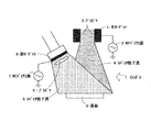
以下に本発明を実施するために必要なスパッタリング装置の構成を図1に示す。主スパッタリング源としてリモートプラズマを仮定しており、円筒型LiNbO3の主ターゲット1にRFバイアス源2によりRF電圧を印加すると、プラズマ3中に生成したアルゴンイオンがターゲット1に衝突して、Li、Nb、酸素原子およびそれらが結びついた分子などのスパッタリング粒子流4が下流に置かれた基板5の上に降り注ぐ。
FIG. 1 shows the configuration of a sputtering apparatus necessary for carrying out the present invention. Remote plasma is assumed as the main sputtering source. When an RF voltage is applied to the main target 1 of cylindrical LiNbO 3 by the
副スパッタリング源は主スパッタリング源による成膜を補助する目的であるから、粒子フラックスはそれ程大きくなくてよいため、この装置では簡易型のスパッタリング源(ECRあるいはRF)を仮定している。この実施例ではLi2Oを副ターゲット6に用いる。RFバイアス源7によりRF電圧を副ターゲット6に印加することにより、Li、酸素原子およびLiO、Li2Oなどのスパッタリング粒子8が基板5の上に降り注ぐ。また真空チャンバ内に酸素ガスを導入することにより、プラズマ9で生成した酸素原子も基板5の上に降り注ぐ。
Since the sub-sputtering source is intended to assist the film formation by the main sputtering source, the particle flux does not have to be so large, so this apparatus assumes a simple sputtering source (ECR or RF). In this embodiment, Li 2 O is used for the
次に、このスパッタリング装置を用いて定比組成のLiNbO3薄膜を基板5の表面に成膜する条件を決定するための手順を述べる。まず、主スパッタリング源だけを用いてLiNbO3薄膜の成膜を行い、必要十分な量の酸素原子が該薄膜中に含まれるような酸素流量の条件を探す。その条件で成膜すると、Li欠損の組成の薄膜(LiNbO3-X)が成膜するはずである。次に、副スパッタリング源を同時に稼動させ、RFバイアス源7によるRFパワーを調整することにより、Li原子のスパッタリング速度を制御し、薄膜中のLiとNbの含有比が1:1になる条件を求める。以上の2つの条件下で2つのスパッタリング源を同時に稼働させることにより、組成がLi:Nb:O=1:1:3の薄膜が基板5の表面に得られる。 Next, a procedure for determining conditions for forming a LiNbO 3 thin film having a stoichiometric composition on the surface of the substrate 5 using this sputtering apparatus will be described. First, a LiNbO 3 thin film is formed using only the main sputtering source, and a condition of an oxygen flow rate is searched for such that a necessary and sufficient amount of oxygen atoms are contained in the thin film. When the film is formed under such conditions, a thin film (LiNbO3 -x ) having a composition of Li deficiency should be formed. Next, by operating the sub-sputtering source at the same time and adjusting the RF power from the RF bias source 7, the sputtering rate of Li atoms is controlled, and the content ratio of Li and Nb in the thin film becomes 1: 1. Ask. By operating two sputtering sources simultaneously under the above two conditions, a thin film having a composition of Li: Nb: O = 1: 1: 3 is obtained on the surface of the substrate 5.
この実施例1では、LiNbO3薄膜の成膜について述べたが、主ターゲットをLiTaO3に変えて、同様の手続きを経ることにより、組成がLi:Ta:O=1:1:3の薄膜を得ることが可能である。 In Example 1, the film formation of the LiNbO 3 thin film was described. However, by changing the main target to LiTaO 3 and performing the same procedure, a thin film having a composition of Li: Ta: O = 1: 1: 3 was obtained. It is possible to obtain.
実施例2はスパッタリング装置の構成は上記実施例1と同様であるが、副ターゲットとしてMgOを選択する点が異なる。次にこの装置を用いて、欠陥の少ないMgO:LiNbO3薄膜を基板5の表面に成膜する条件を決定する手順を述べる。まず、実施例1と同様に主スパッタリング源だけを用いてLiNbO3薄膜の成膜を行い、必要十分な量の酸素原子が膜中に含まれるような酸素流量の条件を探す。次に、副スパッタリング源を同時に稼動させ、RFバイアス源7によるRFパワーを調整することにより、Mg原子のスパッタリング速度を制御し、薄膜中のLi原子とMg原子の数の和とNb原子の含有比が1:1になる条件を求める。以上の2つの条件下で2つのスパッタリング源を同時に稼働させて得られる薄膜の組成は、(Li+Mg):Nb:O=1:1:3である。 In Example 2, the configuration of the sputtering apparatus is the same as that of Example 1, except that MgO is selected as the sub target. A procedure for determining conditions for forming a MgO: LiNbO 3 thin film with few defects on the surface of the substrate 5 using this apparatus will be described below. First, the LiNbO 3 thin film is formed using only the main sputtering source in the same manner as in Example 1, and the condition of the oxygen flow rate is searched for such that a necessary and sufficient amount of oxygen atoms are contained in the film. Next, the sub-sputtering source is operated simultaneously, and the RF power from the RF bias source 7 is adjusted to control the sputtering rate of Mg atoms, so that the sum of the number of Li atoms and Mg atoms in the thin film and the content of Nb atoms are contained. Find the condition that the ratio is 1: 1. The composition of the thin film obtained by simultaneously operating two sputtering sources under the above two conditions is (Li + Mg): Nb: O = 1: 1: 3.
この実施例2では、LiNbO3薄膜の成膜について述べたが、主ターゲットをLiTaO3に変えて、同様の手続きを経ることにより、組成が(Li+Mg):Ta:O=1:1:3の薄膜を得ることが可能である。 In Example 2, the film formation of the LiNbO 3 thin film was described, but the composition was (Li + Mg): Ta: O = 1: 1: 3 by changing the main target to LiTaO 3 and going through the same procedure. It is possible to obtain a thin film.
1:主ターゲット
2:RFバイアス源
3:プラズマ
4:スパッタリング粒子流
5:基板
6:副ターゲット
7:RFバイアス源
8:スパッタリング粒子流
9:プラズマ
1: Main target 2: RF bias source 3: Plasma 4: Sputtered particle flow 5: Substrate 6: Sub target 7: RF bias source 8: Sputtered particle flow 9: Plasma
Claims (11)
LiNbO3又はLiTaO3を主ターゲットとするECRスパッタリングとLi2O又はMgOを副ターゲットとするスパッタリングを同時に行って前記基板表面への前記成膜を行い、かつ前者のスパッタリング速度に対して後者のスパッタリング速度を独立に制御することを特徴とする薄膜形成方法。 In a thin film forming method of forming a LiNbO 3 thin film or a LiTaO 3 thin film on a substrate surface by sputtering,
ECR sputtering using LiNbO 3 or LiTaO 3 as a main target and sputtering using Li 2 O or MgO as a sub-target are performed simultaneously to form the film on the substrate surface, and the latter sputtering with respect to the former sputtering rate. A method for forming a thin film, wherein the speed is controlled independently.
その後、同時にLi2Oを副ターゲットとするスパッタリングを行いスパッタリング速度を制御して前記薄膜中のLiとNbが所定の含有比になる第2の条件を求め、
前記求められた第1および第2の条件下で前記主ターゲットおよび副ターゲットにより同時にスパッタリングを行い、基板表面にLiNbO3薄膜を成膜することを特徴とする薄膜形成方法。 LiNbO 3 is used as a main target to form a LiNbO 3 film on the surface of the substrate by ECR sputtering, and a first condition of the oxygen flow rate in which a necessary amount of oxygen atoms are contained in the thin film is obtained.
Thereafter, sputtering is performed using Li 2 O as a sub-target at the same time to control the sputtering rate to obtain a second condition in which Li and Nb in the thin film have a predetermined content ratio,
A thin film forming method, wherein sputtering is simultaneously performed by the main target and the sub target under the obtained first and second conditions to form a LiNbO 3 thin film on a substrate surface.
前記第2の条件を、前記薄膜中のLiとNbの含有比が1:1となる条件とし、基板表面に組成がLi:Nb:O=1:1:3のLiNbO3薄膜を成膜することを特徴とする薄膜形成方法。 In the thin film formation method of Claim 2,
The second condition is a condition in which the content ratio of Li and Nb in the thin film is 1: 1, and a LiNbO 3 thin film having a composition of Li: Nb: O = 1: 1: 3 is formed on the substrate surface. A method for forming a thin film.
その後、同時にLi2Oを副ターゲットとするスパッタリングを行いスパッタリング速度を制御して前記薄膜中のLiとTaが所定の含有比になる第2の条件を求め、
前記求められた第1および第2の条件下で前記主ターゲットおよび副ターゲットにより同時にスパッタリングを行い、基板表面にLiTaO3薄膜を成膜することを特徴とする薄膜形成方法。 Obtains a first condition of oxygen flow rate the oxygen atom of the amount required by performing the deposition of LiTaO 3 to the substrate surface is contained in the thin film by ECR sputtering to a LiTaO 3 as a main target,
Thereafter, sputtering is performed using Li 2 O as a sub-target at the same time to control the sputtering rate to obtain a second condition in which Li and Ta in the thin film have a predetermined content ratio,
A thin film forming method comprising performing sputtering simultaneously with the main target and the sub target under the obtained first and second conditions to form a LiTaO 3 thin film on a substrate surface.
前記第2の条件を、前記薄膜中のLiとTaの含有比が1:1となる条件とし、基板表面に組成がLi:Ta:O=1:1:3のLiTaO3薄膜を成膜することを特徴とする薄膜形成方法。 In the thin film formation method of Claim 4,
The second condition is a condition in which the content ratio of Li and Ta in the thin film is 1: 1, and a LiTaO 3 thin film having a composition of Li: Ta: O = 1: 1: 3 is formed on the substrate surface. A method for forming a thin film.
その後、前記ECRスパッタリングと同時にMgOを副ターゲットとするスパッタリングを行いスパッタリング速度を制御して前記薄膜中のLi原子とMg原子の数の和とNb原子が所定の含有比になる第2の条件を求め、
前記求められた第1および第2の条件下で前記主ターゲットおよび副ターゲットにより同時にスパッタリングを行い、基板表面にLiNbO3薄膜を成膜することを特徴とする薄膜形成方法。 LiNbO 3 is used as a main target to form a LiNbO 3 film on the surface of the substrate by ECR sputtering, and a first condition of the oxygen flow rate in which a necessary amount of oxygen atoms are contained in the thin film is obtained.
Thereafter, simultaneously with the ECR sputtering, sputtering using MgO as a sub-target is performed to control the sputtering rate, and the second condition is that the sum of the number of Li atoms and Mg atoms in the thin film and the Nb atoms become a predetermined content ratio. Seeking
A thin film forming method, wherein sputtering is simultaneously performed by the main target and the sub target under the obtained first and second conditions to form a LiNbO 3 thin film on a substrate surface.
前記第2の条件を、前記薄膜中のLi原子とMg原子の数の和とNb原子の含有比が1:1となる条件とし、基板表面に組成が(Li+Mg):Nb:O=1:1:3の薄膜を成膜することを特徴とする薄膜形成方法。 In the thin film formation method of Claim 6,
The second condition is such that the sum of the number of Li atoms and Mg atoms in the thin film and the content ratio of Nb atoms is 1: 1, and the composition on the substrate surface is (Li + Mg): Nb: O = 1: A thin film forming method, comprising forming a 1: 3 thin film.
その後、同時にMgOを副ターゲットとするスパッタリングを行いスパッタリング速度を制御して前記薄膜中のLi原子とMg原子の数の和とNb原子が所定の含有比になる第2の条件を求め、
前記求められた第1および第2の条件下で前記主ターゲットおよび副ターゲットにより同時にスパッタリングを行い、基板表面にLiTaO3薄膜を成膜することを特徴とする薄膜形成方法。 Obtains a first condition of oxygen flow rate the oxygen atom of the amount required by performing the deposition of LiTaO 3 to the substrate surface is contained in the thin film by ECR sputtering to a LiTaO 3 as a main target,
Thereafter, sputtering is performed using MgO as a sub-target at the same time to control the sputtering rate to obtain the second condition that the sum of the number of Li atoms and Mg atoms in the thin film and the Nb atoms become a predetermined content ratio,
A thin film forming method comprising performing sputtering simultaneously with the main target and the sub target under the obtained first and second conditions to form a LiTaO 3 thin film on a substrate surface.
前記第2の条件を、前記薄膜中のLi原子とMg原子の数の和とNb原子の含有比が1:1となる条件とし、基板表面に組成が(Li+Mg):Ta:O=1:1:3の薄膜を成膜することを特徴とする薄膜形成方法。 In the thin film formation method of Claim 8,
The second condition is such that the sum of the number of Li atoms and Mg atoms in the thin film and the content ratio of Nb atoms is 1: 1, and the composition on the substrate surface is (Li + Mg): Ta: O = 1: A thin film forming method, comprising forming a 1: 3 thin film.
前記副スパッタリング源は、ECR法又はRF法によるスパッタリング源であることを特徴とする薄膜形成装置。 The thin film forming apparatus according to claim 10,
The sub-sputtering source is a sputtering source based on an ECR method or an RF method.
Priority Applications (1)
| Application Number | Priority Date | Filing Date | Title |
|---|---|---|---|
| JP2004170665A JP4265782B2 (en) | 2004-06-09 | 2004-06-09 | Thin film forming method and apparatus |
Applications Claiming Priority (1)
| Application Number | Priority Date | Filing Date | Title |
|---|---|---|---|
| JP2004170665A JP4265782B2 (en) | 2004-06-09 | 2004-06-09 | Thin film forming method and apparatus |
Publications (2)
| Publication Number | Publication Date |
|---|---|
| JP2005350706A JP2005350706A (en) | 2005-12-22 |
| JP4265782B2 true JP4265782B2 (en) | 2009-05-20 |
Family
ID=35585430
Family Applications (1)
| Application Number | Title | Priority Date | Filing Date |
|---|---|---|---|
| JP2004170665A Expired - Fee Related JP4265782B2 (en) | 2004-06-09 | 2004-06-09 | Thin film forming method and apparatus |
Country Status (1)
| Country | Link |
|---|---|
| JP (1) | JP4265782B2 (en) |
Cited By (2)
| Publication number | Priority date | Publication date | Assignee | Title |
|---|---|---|---|---|
| US7909454B2 (en) | 2004-09-02 | 2011-03-22 | Haruhiko Koto | Inkjet printing press |
| RU2762756C1 (en) * | 2021-04-19 | 2021-12-22 | Федеральное государственное бюджетное образовательное учреждение высшего образования "Воронежский государственный технический университет" | Method for obtaining thin films of lithium niobate on substrate |
Families Citing this family (3)
| Publication number | Priority date | Publication date | Assignee | Title |
|---|---|---|---|---|
| JP2008069058A (en) * | 2006-09-15 | 2008-03-27 | Nippon Telegr & Teleph Corp <Ntt> | Method for forming LiNbO3 epitaxial film |
| CN105714258B (en) * | 2016-02-25 | 2019-02-12 | 深圳大学 | Device and method for dual-source sputtering alloy thin film |
| US20260049390A1 (en) * | 2022-08-09 | 2026-02-19 | Jsw Afty Corporation | Film forming apparatus and film forming method |
-
2004
- 2004-06-09 JP JP2004170665A patent/JP4265782B2/en not_active Expired - Fee Related
Cited By (2)
| Publication number | Priority date | Publication date | Assignee | Title |
|---|---|---|---|---|
| US7909454B2 (en) | 2004-09-02 | 2011-03-22 | Haruhiko Koto | Inkjet printing press |
| RU2762756C1 (en) * | 2021-04-19 | 2021-12-22 | Федеральное государственное бюджетное образовательное учреждение высшего образования "Воронежский государственный технический университет" | Method for obtaining thin films of lithium niobate on substrate |
Also Published As
| Publication number | Publication date |
|---|---|
| JP2005350706A (en) | 2005-12-22 |
Similar Documents
| Publication | Publication Date | Title |
|---|---|---|
| JP5093943B2 (en) | Method of fabricating piezoelectric film using rotating magnetron sputtering system | |
| JP3462265B2 (en) | Wavelength conversion element | |
| JP4265782B2 (en) | Thin film forming method and apparatus | |
| US4994320A (en) | Thin magnetic film having long term stabilized uniaxial anisotropy | |
| Felmetsger et al. | Innovative technique for tailoring intrinsic stress in reactively sputtered piezoelectric aluminum nitride films | |
| US6195191B1 (en) | Optical devices having improved temperature stability | |
| Akazawa | Trials to achieve high-quality c-axis-oriented LiNbO3 thin films: Sputter-deposition on a-SiO2, ZnO/SiO2, quartz (0001), and SrTiO3 (111) substrates | |
| JP3424125B2 (en) | Optical functional device using ferroelectric polarization reversal of lithium tantalate single crystal | |
| JPH0769495B2 (en) | Method for manufacturing optical stripline waveguide | |
| Tomov et al. | LiNbO3 optical waveguides deposited on sapphire by electric-field-assisted pulsed laser deposition | |
| Ivanov et al. | Analysis of ion exchanged Me: LiNbO3 and Cu: LiTaO3 waveguides by AES, SAM, EPR and optical methods | |
| US20030180984A1 (en) | Diamond substrate having piezoelectric thin film, and method for manufacturing it | |
| JP4055939B2 (en) | LiNbO3 thin film forming method | |
| Xie et al. | Large anisotropic room-temperature ferromagnetism in yttrium-doped HfO2 thin film | |
| JP2004244703A (en) | Method for forming LiNbO3 oriented thin film | |
| JPH0280561A (en) | Production of iron garnet layer and obtained waveguide | |
| JP2008069058A (en) | Method for forming LiNbO3 epitaxial film | |
| JP4929842B2 (en) | ND filter and method of manufacturing ND filter | |
| JP3444949B2 (en) | Loading film on ferroelectric crystal substrate and method of forming the same | |
| Kingston et al. | C− outgrowths in C+ thin films of LiNbO3 on Al2O3-c | |
| JP2006219339A (en) | LiNbO3 crystal thin film deposition method | |
| JPH0444812B2 (en) | ||
| Tunaboylu | Synthesis, deposition and characterization of ferroelectric films for electrooptic devices | |
| JPH04170396A (en) | Production of thin film of lithium niobate single crystal | |
| Cheng et al. | Temperature effect on the characteristics of surface acoustic wave on SiO/sub 2/thin films |
Legal Events
| Date | Code | Title | Description |
|---|---|---|---|
| A621 | Written request for application examination |
Free format text: JAPANESE INTERMEDIATE CODE: A621 Effective date: 20060719 |
|
| A977 | Report on retrieval |
Free format text: JAPANESE INTERMEDIATE CODE: A971007 Effective date: 20090206 |
|
| TRDD | Decision of grant or rejection written | ||
| A01 | Written decision to grant a patent or to grant a registration (utility model) |
Free format text: JAPANESE INTERMEDIATE CODE: A01 Effective date: 20090210 |
|
| A01 | Written decision to grant a patent or to grant a registration (utility model) |
Free format text: JAPANESE INTERMEDIATE CODE: A01 |
|
| A61 | First payment of annual fees (during grant procedure) |
Free format text: JAPANESE INTERMEDIATE CODE: A61 Effective date: 20090210 |
|
| R150 | Certificate of patent or registration of utility model |
Free format text: JAPANESE INTERMEDIATE CODE: R150 |
|
| FPAY | Renewal fee payment (event date is renewal date of database) |
Free format text: PAYMENT UNTIL: 20120227 Year of fee payment: 3 |
|
| FPAY | Renewal fee payment (event date is renewal date of database) |
Free format text: PAYMENT UNTIL: 20130227 Year of fee payment: 4 |
|
| LAPS | Cancellation because of no payment of annual fees |