JP4265760B2 - Writing instrument - Google Patents
Writing instrument Download PDFInfo
- Publication number
- JP4265760B2 JP4265760B2 JP2003314559A JP2003314559A JP4265760B2 JP 4265760 B2 JP4265760 B2 JP 4265760B2 JP 2003314559 A JP2003314559 A JP 2003314559A JP 2003314559 A JP2003314559 A JP 2003314559A JP 4265760 B2 JP4265760 B2 JP 4265760B2
- Authority
- JP
- Japan
- Prior art keywords
- ink
- guide tube
- writing instrument
- writing
- ink guide
- Prior art date
- Legal status (The legal status is an assumption and is not a legal conclusion. Google has not performed a legal analysis and makes no representation as to the accuracy of the status listed.)
- Expired - Fee Related
Links
Images
Landscapes
- Pens And Brushes (AREA)
- Mechanical Pencils And Projecting And Retracting Systems Therefor, And Multi-System Writing Instruments (AREA)
Description
本発明は、軸筒内のインキ吸蔵体に含浸された水性インキ、油性インキなどの筆記具用インキを筆記部となるペン先に供給する筆記具に関し、更に詳しくは、この構造の筆記具においてインキの終了サインを簡単に検知することができる筆記具に関する。 The present invention relates to a writing instrument that supplies ink for a writing instrument such as water-based ink or oil-based ink impregnated in an ink occlusion body in a shaft cylinder to a pen tip serving as a writing part. The present invention relates to a writing instrument that can easily detect a signature.
従来より、インキの残量・インキの終了サインを知ることができる筆記具としては、例えば、軸体内に直接液状インキを収容してなるコレクター構造を有する直液筆記具、インキがカートリッジ式のインキ収容管に収容された構造の筆記具、透明のリフィールにボールペン用インキが充填されたタイプのボールぺンなどが知られている。 Conventionally, as a writing instrument that can know the remaining amount of ink and the ink end signature, for example, a direct liquid writing instrument having a collector structure in which liquid ink is directly stored in the shaft, an ink cartridge type ink storage tube A writing instrument with a structure housed in a ballpoint pen, a ball pen with a transparent refill filled with ballpoint pen ink, and the like are known.
ところで、軸筒内のインキ吸蔵体に含浸された水性インキ、油性インキなどの筆記具用インキを筆記部となるペン先に供給する筆記具、所謂中綿式の筆記具にあっては、今までインキ終了サインを検知できる機構を具備した筆記具はないのが現状である。
そのため、この構造の筆記具では、筆記中にインキがカスレるまで使用して初めてインキの終了が判り、その後、廃棄又はインキを補充することにより再使用されるものであるが、カスレはペン先の乾燥等によっても生じるため、インキ吸蔵体に含浸されたインキが十分あるにも拘わらずペン先の乾燥等によりカスレた場合等には本来のインキの終了サインではなく、使用性等に課題があるものである。
By the way, in the case of writing instruments that supply ink for writing instruments such as water-based ink and oil-based ink impregnated in the ink occlusion body in the shaft cylinder to the pen tip serving as the writing section, so-called batting type writing instruments, the ink end sign has been used so far. At present, there is no writing instrument equipped with a mechanism capable of detecting the above.
For this reason, in the writing instrument of this structure, the end of the ink can be recognized only after the ink is used up until it becomes dull during writing, and then reused by discarding or replenishing the ink. Since it also occurs due to drying, etc., there is a problem in usability, not the original ink end sign, when the ink occlusion body has enough ink impregnated and it becomes dull due to drying of the nib etc. Is.
一方、透明な軸筒内にインキ吸蔵体となる中綿が収納され、該中綿に含浸されたインキを筆記部となるペン先に供給されると共に、中綿からペン先まで筆記具の中身を視認することができる筆記具(例えば、特許文献1参照)が知られている。
しかしながら、この構造の筆記具にあっては、中綿に吸蔵されたインキ量が少なくなれば吸蔵されているインキ色の度合いによりある程度のインキ残量は確認することができるが、確実にインキの終了サインを検知できるものではなく、この筆記具にあっても使用性等に課題があるものである。
However, with writing instruments with this structure, if the amount of ink stored in the batting is reduced, a certain amount of remaining ink can be confirmed depending on the degree of stored ink color, but it is certain that the ink has ended. This writing instrument has problems in usability and the like.
本発明は、上記従来技術の課題及び現状等に鑑み、これを解消しようとするものであり、軸筒内のインキ吸蔵体に含浸された水性インキ、油性インキなどの筆記具用インキを筆記部となるペン先に供給する筆記具において、インキの終了サインをきわめて簡単に、かつ、確実に検知することができる筆記具を提供することを目的とする。 The present invention is to solve this problem in view of the above-described problems of the prior art and the current situation, and to write ink for writing instruments such as water-based ink and oil-based ink impregnated in the ink occlusion body in the shaft cylinder with the writing unit. An object of the present invention is to provide a writing instrument that can detect an ink end sign very easily and reliably.
本発明者は、上記従来の課題等を解決するために、鋭意検討した結果、軸筒内のインキ吸蔵体に含浸されたインキを筆記部となるペン先に供給する筆記具における軸筒の構成、並びに、インキ吸蔵体からペン先にインキを供給する機構を特定の構成等とすることにより、上記目的の筆記具が得られることを見いだし、本発明を完成するに至ったのである。 As a result of intensive investigations to solve the above-described conventional problems, the present inventor has a configuration of a shaft cylinder in a writing instrument that supplies ink impregnated in an ink occlusion body in a shaft cylinder to a pen tip serving as a writing unit, In addition, the inventors have found that the above-described writing instrument can be obtained by setting the mechanism for supplying ink from the ink occlusion body to the pen tip with a specific configuration, and the present invention has been completed.
すなわち、本発明は、次の(1)〜(13)に存する。
(1)軸筒内のインキ吸蔵体に含浸されたインキを筆記部となるペン先に供給する筆記具であって、上記インキ吸蔵体に含浸されたインキは、視認性を有する熱可塑性樹脂で形成された少なくともインキと接する面にインキハジキ層を形成してなるインキ誘導管を介してペン先に供給されると共に、インキ吸蔵体からのインキ終了サインを軸筒に形成した視認部を介して上記インキ誘導管を視認することにより検知することを特徴とする筆記具。
(2)軸筒内のインキ吸蔵体に含浸されたインキを軸筒の両側に設けた筆記部となる各ペン先に供給するツインタイプの筆記具であって、少なくとも一方のペン先に供給されるインキは、視認性を有する熱可塑性樹脂で形成された少なくともインキと接する面にインキハジキ層を形成してなるインキ誘導管を介してペン先に供給されると共に、インキ吸蔵体からのインキ終了サインを少なくとも一方の軸筒に形成した視認部を介して上記インキ誘導管を視認することにより検知することを特徴とする筆記具。
(3)インキ吸蔵体に含浸されたインキは中継芯を介して視認性を有するインキ誘導管へ供給される上記(1)又は(2)記載の筆記具。
(4)インキ誘導管及び軸筒に形成した視認部に用いられる熱可塑性樹脂が、厚さ1mmの時に全光線透過率が60%以上又はヘイズ20%以下である上記(1)〜(3)の何れか一つに記載の筆記具。
(5)インキハジキ層がパーフルオロアルキル基を有するフッ素樹脂をコーティングしたコーティング層からなる上記(1)〜(4)の何れか一つに記載の筆記具。
(6)インキハジキ層がジメチルシリコーンを有するシリコーンワニスの硬化物からなる上記(1)〜(4)の何れか一つに記載の筆記具。
(7)シリコーンワニスの硬化機構が、縮合型、付加型、UV型の何れかである上記(6)記載の筆記具。
(8)シリコーンワニスには、シリカ微粒子が含有されている上記(6)又は(7)記載の筆記具。
(9)インキハジキ層がアクリル系樹脂にジメチルシリコーン又はパーフルオロアルキル基又はこれらの両方がグラフトしてなるコーティング層からなる上記(1)〜(4)の何れか一つに記載の筆記具。
(10)インキハジキ層は、インキ誘導管の表面を活性化処理した後に形成される上記(1)〜(9)の何れか一つに記載の筆記具。
(11)インキハジキ層は、インキ誘導管の表面に接着層を形成した後に形成される上記(1)〜(9)の何れか一つに記載の筆記具。
(12)インキハジキ層は、インキ誘導管の表面を活性化処理した後に、更に接着層を形成した後に形成される上記(1)〜(9)の何れか一つに記載の筆記具。
(13)インキハジキ層が、0.05〜200μmの厚みで構成されている上記(1)〜(12)の何れか一つに記載の筆記具。
That is, the present invention resides in the following (1) to (13).
(1) A writing instrument for supplying ink impregnated in an ink occlusion body in a shaft cylinder to a pen tip serving as a writing part, wherein the ink impregnated in the ink occlusion body is formed of a thermoplastic resin having visibility. The ink is supplied to the pen tip through an ink guide tube formed with an ink repellency layer at least on the surface in contact with the ink, and the ink end sign from the ink occlusion body is formed on the shaft tube through the visual recognition portion. Writing instrument characterized by detecting by visually recognizing a guide tube.
(2) A twin type writing instrument that supplies ink impregnated in the ink occlusion body in the shaft cylinder to each pen tip serving as a writing section provided on both sides of the shaft cylinder, and is supplied to at least one of the pen tips. Ink is supplied to the pen tip through an ink guide tube formed with an ink repellent layer on at least the surface in contact with the ink formed of a visible thermoplastic resin, and an ink end sign from the ink occlusion body is also provided. A writing instrument characterized by detecting by visually recognizing the ink guide tube through a visual recognition portion formed on at least one of the shaft cylinders.
(3) The writing instrument according to (1) or (2), wherein the ink impregnated in the ink occlusion body is supplied to an ink guide tube having visibility through a relay core.
(4) Said (1)-(3) whose total light transmittance is 60% or more or a
(5) The writing instrument according to any one of (1) to (4), wherein the ink repellent layer is a coating layer coated with a fluororesin having a perfluoroalkyl group.
(6) The writing instrument according to any one of (1) to (4), wherein the ink repellency layer is formed of a cured product of a silicone varnish having dimethyl silicone.
(7) The writing instrument according to (6) above, wherein the curing mechanism of the silicone varnish is any one of a condensation type, an addition type, and a UV type.
(8) The writing instrument according to (6) or (7), wherein the silicone varnish contains silica fine particles.
(9) The writing instrument according to any one of the above (1) to (4), wherein the ink repellent layer is a coating layer formed by grafting a dimethyl silicone or a perfluoroalkyl group or both of them onto an acrylic resin.
(10) The writing instrument according to any one of (1) to (9), wherein the ink repellent layer is formed after the surface of the ink guide tube is activated.
(11) The writing instrument according to any one of (1) to (9), wherein the ink repellent layer is formed after an adhesive layer is formed on the surface of the ink guide tube.
(12) The writing instrument according to any one of (1) to (9), wherein the ink repellent layer is formed after the surface of the ink guide tube is activated and further formed with an adhesive layer.
(13) The writing instrument according to any one of (1) to (12) above, wherein the ink repellent layer has a thickness of 0.05 to 200 μm.
本発明によれば、軸筒内のインキ吸蔵体に含浸されたインキを筆記部となるペン先に供給する筆記具であっても、簡単な構成により、インキの終了サインを軸筒に形成した視認部を介して視認性を有する熱可塑性樹脂で形成された少なくともインキと接する面にインキハジキ層を形成してなるインキ誘導管を視認することにより、きわめて簡単に、かつ、確実に検知することができると共に、インキ流出量も直液式筆記具のようにインキ終了までほぼ一定で、良好な描線を描くことができる筆記具が提供されることとなる。
また、中継芯を介してインキ吸蔵体に含浸されたインキをインキ誘導管に供給する構造の筆記具では、インキ吸蔵体に含浸されたインキを更に効率よく、スムーズにインキ誘導管に導入せしめることができる筆記具が提供されることとなる。
According to the present invention, even with a writing instrument that supplies the ink impregnated in the ink occlusion body in the shaft cylinder to the pen tip serving as the writing portion, the visual confirmation that the ink end sign is formed on the shaft cylinder with a simple configuration. By visually recognizing an ink guide tube formed with an ink repellent layer on at least the surface in contact with the ink, which is formed of a thermoplastic resin having visibility through the portion, it can be detected very easily and reliably. At the same time, the amount of ink outflow is almost constant until the end of the ink as in the case of a direct liquid type writing instrument, and a writing instrument capable of drawing a good drawing line is provided.
In addition, in a writing instrument having a structure in which the ink impregnated in the ink occlusion body is supplied to the ink induction tube via the relay core, the ink impregnated in the ink occlusion body can be more efficiently and smoothly introduced into the ink induction tube. A writing instrument that can be used will be provided.
以下に、本発明の実施形態を詳しく説明する。
本発明の筆記具は、第1発明として、軸筒内のインキ吸蔵体に含浸されたインキを筆記部となるペン先に供給する筆記具であって、上記インキ吸蔵体に含浸されたインキは、視認性を有する熱可塑性樹脂で形成された少なくともインキと接する面にインキハジキ層を形成してなるインキ誘導管を介してペン先に供給されると共に、インキ吸蔵体からのインキ終了サインを軸筒に形成した視認部を介して上記インキ誘導管を視認することにより検知することを特徴とするものであり、第2発明として、軸筒内のインキ吸蔵体に含浸されたインキを軸筒の両側に設けた筆記部となる各ペン先に供給するツインタイプの筆記具であって、少なくとも一方のペン先に供給されるインキは、視認性を有する熱可塑性樹脂で形成された少なくともインキと接する面にインキハジキ層を形成してなるインキ誘導管を介してペン先に供給されると共に、インキ吸蔵体からのインキ終了サインを少なくとも一方の軸筒に形成した視認部を介して上記インキ誘導管を視認することにより検知することを特徴とするものであり、更に、第3発明として、上記第1及び第2発明の各筆記具において、インキ吸蔵体に含浸されたインキは中継芯を介して視認性を有するインキ誘導管へ供給される構造の各筆記具から構成されるものであり、サインペン、マーカー、ホワイトボード用マーカー、ボールペン等に好適に適用することができるものである。
Hereinafter, embodiments of the present invention will be described in detail.
The writing instrument of the present invention is a writing instrument that supplies ink impregnated in an ink occlusion body in a shaft cylinder to a pen tip serving as a writing part as the first invention, and the ink impregnated in the ink occlusion body is visible Is supplied to the pen tip through an ink guide tube formed with an ink repellant layer on at least the surface in contact with the ink, which is made of a thermoplastic resin, and an ink end sign from the ink occlusion body is formed on the shaft cylinder In the second aspect of the present invention, ink impregnated in the ink occlusion body in the shaft cylinder is provided on both sides of the shaft cylinder. A twin-type writing instrument to be supplied to each nib serving as a writing part, wherein at least one of the pen nibs is supplied with at least an ink formed of a thermoplastic resin having visibility The ink guide tube is supplied to the pen tip through an ink guide tube formed with an ink repellant layer on the surface to be printed, and the ink end sign from the ink occlusion body is formed on at least one shaft cylinder through a visual recognition portion. Further, as a third invention, in each writing instrument of the first and second inventions, the ink impregnated in the ink occlusion body is visually recognized through a relay core. It is composed of each writing instrument having a structure supplied to an ink guide tube having a property, and can be suitably applied to a sign pen, a marker, a whiteboard marker, a ballpoint pen, and the like.
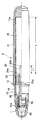
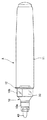
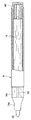
図1〜図3は、本発明の第1実施形態を示すものである。
本第1実施形態の筆記具Aは、図1及び図2に示すように、先軸10と尾栓部を一体に有する後軸11とからなる軸筒12、インキ吸蔵体15、中継芯20、インキ吸蔵体15及び中継芯20を保持する保持部材25、インキ誘導管30、ペン先40、キャップ部材50とを備えている。
先軸10は、熱可塑性樹脂製から構成されるものであり、先端側がテーパー部を有する小径部10aと、大径部10bとが一体となったものであり、該小径部10a内にはペン先40を嵌着する嵌着部11を有すると共に、大径部10b内は保持部材25の前部及びインキ誘導管30を収容する構造となっている。
また、先軸10の大径部10bは、図2に示すように、その内部を視認できるように視認部となっており、それ以外の先軸部分は着色部や装飾部又は別部材等により非視認部となっている。なお、先軸10全体を視認部としてもよい。
1 to 3 show a first embodiment of the present invention.
As shown in FIGS. 1 and 2, the writing instrument A of the first embodiment includes a
The
Further, as shown in FIG. 2, the large-
この視認部となる大径部10b又は先軸全部に用いられる熱可塑性樹脂としては、視認性(透明又は半透明)を有するものであればよく、好ましくは、厚さ1mmの時に全光線透過率が60%以上又はヘイズ(HAZE)20%以下となるものが望ましく、例えば、厚さ1mmの時に全光線透過率が60%以上又はヘイズ20%以下となるポリプロピレン(PP)、ポリエチレン(PE)、環状ポリオレフィン、ポリメチルペンテンなどのポリオレフィン系樹脂、ポリカーボネート(PC)、ポリスチレン、ポリエチレンテレフタレート(PET)、ポリエチレンナフタレート(PEN)やポリブチレンテレフタレート(PBT)、ポリアミド類、ポリイミド、ABS、ポリメチルメタクリレート、AS、EVOH、ポリエーテルイミド、ポリサルホン、並びに、フッ素樹脂、フッ化ビニリデンなどのフッ素プラスチックなどの光学特性を有する熱可塑性樹脂を用いることができる。
The thermoplastic resin used for the large-
この視認部となる大径部10bの全長は、先軸10内に保持されるインキ誘導管30を視認できる長さであればよく、好ましくは、1mm以上、更に好ましくは、5mm以上とすることが望ましい。なお、視認部となる大径部10bの全長が1mm未満であると、インキ終了サインの検知を視認し難く検知機能を果たせないこととなる。本実施形態では、10mmに設定されている。
The total length of the large-
インキ吸蔵体15は、水性インキ、油性インキなどの筆記具用インキを含浸したものであり、例えば、天然繊維、獣毛繊維、ポリアセタール系樹脂、アクリル系樹脂、ポリエステル系樹脂、ポリアミド系樹脂、ポリウレタン系樹脂、ポリオレフィン系樹脂、ポリビニル系樹脂、ポリカーボネート系樹脂、ポリエーテル系樹脂、ポリフェニレン系樹脂などの1種又は2種以上の組み合わせからなる繊維束、フェルト等の繊維束を加工したもの、また、スポンジ、樹脂粒子、焼結体等の多孔体を含むものであり、後軸11の後端保持部11aと先軸10の後部に嵌着する保持部材25の保持部25aとにより軸筒を構成する後軸11内に収容されている。
The
中継芯20は、インキ吸蔵体15と同様に繊維束、フェルト等の繊維束を加工した繊維束芯、または、硬質スポンジ、樹脂粒子焼結体等からなる樹脂粒子多孔体、スライバー芯等の連続気孔(流路)を有するものであり、インキ吸蔵体15に含浸されたインキを該中継芯20を介して視認性を有するインキ誘導管30へ供給できるものであれば、特にその形状、構造等は限定されるものでないが、例えば、図1に示すように、中継芯20の先端部には、インキ誘導管30の後端部内に挿入される凹部20aを有し、その後端部は鋭角な形状となる鋭角部20bを有するものが挙げられる。また、インキ吸蔵体15の先端側中央部分には、上記中継芯20の外層部と接触できる空洞部が設けられている。この図1に示す、凹部20a及び鋭角部20bを有する中継芯20及び空洞部を有するインキ吸蔵体15の構造等により、インキ吸蔵体15に含浸されたインキは中継芯20を介して視認性を有するインキ誘導管30へ効率よく供給できるものとなる。
The
更に、上記中継芯20の毛細管力はインキ吸蔵体15の毛細管力より大きくすること、並びに、中継芯20の断面構造を内層部及び外層部を有する構造とし、外層部の毛細管力が内層部の毛細管力よりも大きくすること、例えば、外層部の繊維束密度を細密部とし、内層部の繊維束密度を粗密部とすることにより、インキ吸蔵体15に含浸されたインキをインキ誘導管30へ効率よく供給できるものとなる。
ここで、中継芯20はインキ吸蔵体15の全長(L)の5%以上、好ましくは、10%以上100%以下の長さでインキ吸蔵体15内部と接触していること、すなわち、中継芯20のインキ吸蔵体15内部と接触する長さL1は、インキ吸蔵体15の全長Lの5%以上、好ましくは10%以上の長さとすることが望ましく、更に好ましくは、20%以上100%以下、特に好ましくは、50%以上100%以下の長さでインキ吸蔵体15内部と接触していることが望ましい。これにより、インキ吸蔵体15に含まれるインキを更にインキ誘導管30へ効率よく供給することができるものとなる。図1に示す中継芯20の長さL1は、インキ吸蔵体15の全長Lの15%に設定されている。なお、インキ吸蔵体15内部と接触する長さが5%未満であると、通常の中綿式の筆記具と同レベルのインキ消費率となってしまう場合がある。
Further, the capillary force of the
Here, the
更に、中継芯20の断面積は、インキ吸蔵体15の断面積の1〜90%、好ましくは、5〜50%、更に好ましくは、10〜25%とすることが望ましい。
この中継芯20の断面積が1%未満であると、ペン先40の形態にもよるが、インキ吸蔵体15からのインキ供給量が不足し描線カスレや早書き追従性に劣るなどの問題を生じ、また、90%を越えると、インキ吸蔵体15中に挿入し難くなるばかりでなくインキ吸蔵体15としての機能が小さくなり中継芯20とした従来からある中綿式の筆記具と何等変わらないものとなる。
上記中継芯20の断面積をインキ吸蔵体15の断面積の1〜90%に設定することにより、インキ吸蔵体15に含まれるインキを更にインキ誘導管30へ効率よく供給することができるものとなる。なお、図1に示す中継芯20の断面積は、インキ吸蔵体15の断面積の23.3%に設定されている。
Further, the cross-sectional area of the
If the cross-sectional area of the
By setting the cross-sectional area of the
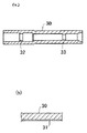
インキ誘導管30は、図1〜図3に示すように、視認性を有すると共に、中継芯20及びペン先を嵌入する形状を有する筒状(環状)のインキ流路部材となるものであり、熱可塑性樹脂から構成されている。インキ誘導管30としては、視認性(透明又は半透明)を有するものであればよく、厚さ1mmの時に全光線透過率が60%以上又はヘイズ20%以下となる熱可塑性樹脂が好ましく、例えば、全光線透過率が60%以上又はヘイズ20%以下となるポリプロピレン(PP)、ポリエチレン(PE)、環状ポリオレフィン、ポリメチルペンテンなどのポリオレフィン系樹脂、ポリカーボネート(PC)、ポリスチレン、ポリエチレンテレフタレート(PET)、ポリエチレンナフタレート(PEN)やポリブチレンテレフタレート(PBT)、ポリアミド類、ポリイミド、ABS、ポリメチルメタクリレート、AS、EVOH、ポリエーテルイミド、ポリサルホン、並びに、フッ素樹脂、フッ化ビニリデンなどのフッ素プラスチックなどの光学特性を有する熱可塑性樹脂を用いることができる。
As shown in FIGS. 1 to 3, the
本発明において、視認性を有する上記特性の熱可塑性樹脂で形成されたインキ誘導管30は、図3(b)に示すように、少なくともインキと接する面にインキハジキ層31を形成してなるものである。
このインキハジキ層31は、視認性及びインキハジキ性に優れ、インキ誘導管30内を流通するインキの付着、残存防止機能を有し、これによりインキ終了サインをきわめて容易に確認(視認)するために形成するものである。
このインキハジキ層31としては、例えば、パーフルオロアルキル基を有するフッ素樹脂をコーティングしたコーティング層からなるもの、ジメチルシリコーンを有するシリコーンワニスの硬化物からなるもの、上記シリコーンワニスの硬化機構が、縮合型、付加型、UV型の何れかであるもの、更に、上記シリコーンワニスにはシリカ微粒子が含有してなるもの、アクリル系樹脂にジメチルシリコーン又はパーフルオロアルキル基又はこれらの両方がグラフトしてなるコーティング層からなるものが挙げられる。
In the present invention, the
This
Examples of the
上記インキハジキ層を構成するシリコーンワニスの硬化物としては、例えば、付加型、UV型、縮合型が挙げられ、付加型は硬化時の副生成物がなく、深部まで硬化する点で優れ、また、UV型は硬化性及び取り扱い性に優れている。上記縮合型には、脱アルコール型、脱オキシウム型、脱酢酸型、脱アミン型、脱アミド型、脱アミノキシ型、脱アセトン型、脱水素型、脱水型などがあり、また、これらは一液型又はニ液型で硬化するものである。本発明においては、インキ誘導管の材質、用いるインキ種等により最も好適となる付加型、UV型、縮合型から選択してシリコーンワニスの硬化物からなるインキハジキ層を構成することができ、特に、作業性、使用性、コスト、インキハジキ性に優れる点から縮合型が好ましく、更に好ましくはエタノール系インキに対してもシリコーンワニスの硬化物中で最も優れるインキハジキ性を有する点から、一液型の脱オキシウム型が特に望ましい。
また、上記シリコーンワニスにシリカ微粒子が含有してなるコーティング層は、シリコーンワニス硬化物単独からなるインキハジキ層に較べ、更にその硬度、強度を向上させるものである。すなわち、シリコーンは本質的に分子間力が低く、非結晶構造であるため硬度、強度が若干弱く、塗膜が破壊されやすいことがある。そのため、シリカ等を充填することにより硬度、強度を向上させることができる。シリカ中にあるシラノール基とシリコーンワニスが加水分解した後のシラノール基と脱水縮合反応によりシロキサン結合して科学的に強固に結合して硬度、強度を向上させることができるものとなる。シリカの含有量はシリコーンワニス中のシリコーンに対して、重量で1〜100%、好ましくは、5〜50%とすることが望ましく、また、シリカは非晶質シリカが望ましい。
これらのインキハジキ層を形成する材料としては、例えば、X−31−608−T(脱オキシウム型:シリコーン20wt%に対して非晶質シリカ粒子を5wt%含有、信越化学工業社製)、VF−304VC(フッ素樹脂の2wt%溶液、溶剤:CF3CF2CHFCHFCF3、INTスクリーン社製)、SG−204(ポリシロキサングラフトポリマー、日本触媒社製)、No.309(フッ素樹脂の15wt%溶液、溶剤:イソへキサン/アセトン混合溶媒、INTスクリーン社製)、JS−025(ポリシロキサングラフトアクリル樹脂、日本ペイント社製)、INT−304VB(フッ素樹脂の4wt%溶液、溶剤:CF3CF2CHFCHFCF3、INTスクリーン社製)、テフロン(登録商標)AF1600(三井・デュポンフロロケミカル社製)、サイトップTL110A、同CTL110S(旭硝子社製)等を用いることができる。
Examples of the cured product of the silicone varnish constituting the ink repellent layer include an addition type, a UV type, and a condensation type, and the addition type has no by-product at the time of curing, and is excellent in that it cures to a deep part. The UV type is excellent in curability and handleability. The above condensation types include dealcohol, deoxime, deacetate, deamine, deamid, deaminoxy, deacetone, dehydrogenate, and dehydrated types. It cures in a mold or a two-part type. In the present invention, an ink repellency layer made of a cured product of a silicone varnish can be configured by selecting from the addition type, UV type, and condensation type that are most suitable depending on the material of the ink guide tube, the type of ink used, etc. The condensation type is preferable because it is excellent in workability, usability, cost, and ink repelling property, and more preferably, it is one-part type removal from the point that it has the most excellent ink repelling property among cured silicone varnishes even for ethanol-based inks. Oxium type is particularly desirable.
Moreover, the coating layer in which silica fine particles are contained in the silicone varnish further improves the hardness and strength thereof compared to an ink repellant layer made of a cured silicone varnish alone. That is, since silicone has an essentially low intermolecular force and an amorphous structure, the hardness and strength are slightly weak and the coating film may be easily broken. Therefore, the hardness and strength can be improved by filling silica or the like. Silanol groups in the silica and the silanol groups after the silicone varnish are hydrolyzed and siloxane bonds by a dehydration condensation reaction, and are chemically bonded firmly to improve hardness and strength. The content of silica is 1 to 100% by weight, preferably 5 to 50%, based on the silicone in the silicone varnish, and the silica is preferably amorphous silica.
As materials for forming these ink repellency layers, for example, X-31-608-T (deoxynium type: containing 5 wt% of amorphous silica particles with respect to 20 wt% of silicone, manufactured by Shin-Etsu Chemical Co., Ltd.), VF- 304VC (2 wt% solution of fluororesin, solvent: CF 3 CF 2 CHFCHFCF 3 , manufactured by INT Screen), SG-204 (polysiloxane graft polymer, manufactured by Nippon Shokubai Co.), No. 309 (15 wt% solution of fluororesin, solvent: isohexane / acetone mixed solvent, manufactured by INT Screen), JS-025 (polysiloxane graft acrylic resin, manufactured by Nippon Paint), INT-304VB (4 wt% of fluororesin) Solution, solvent: CF 3 CF 2 CHFCHFCF 3 (manufactured by INT Screen), Teflon (registered trademark) AF1600 (manufactured by Mitsui / DuPont Fluorochemical), Cytop TL110A, CTL110S (manufactured by Asahi Glass Co., Ltd.) and the like can be used. .
インキハジキ層31の形成方法としては、例えば、上記パーフルオロアルキル基を有するフッ素樹脂、上記ジメチルシリコーンを有するシリコーンワニス(付加型、UV型、縮合型)又はシリカ微粒子を含有するもの、上記グラフト樹脂等をそのまま塗布、または適宜、MCH(メチルシクロヘキサン、以下同様)、IPA/トルエンの混合液溶媒、n−PAなどの溶媒に溶解してインキ誘導管30の内面に塗布することにより、または、これらのインキ誘導管30を前記各コーティング樹脂液中等に浸漬処理すること(ディッピング法)等により、インキ誘導管30の少なくともインキと接する面にインキハジキ層31を形成することができる。
Examples of the method for forming the
本発明では、インキハジキ層31を形成する前に、インキ誘導管30の内面に更に強固にインキハジキ層31を密着せしめる点から、インキ誘導管30の表面を活性化処理した後にインキハジキ層31を形成したり、インキ誘導管の表面に接着層を形成した後にインキハジキ層31を形成したり、インキ誘導管30の表面を活性化処理した後に、更に接着層を形成した後にインキハジキ層31を形成してもよいものである。
活性化処理としては、例えば、オゾン処理、プラズマ処理、コロナ処理、紫外線照射処理、高圧放電処理及び酸処理から選ばれる少なくとも1種の活性化処理が挙げられる。
オゾン処理としては、インキ誘導管表面をオゾン分子と接触させて、ヒドロキシペルオキシ基や水酸基やカルボニル基等の官能基を導入することを目的とし、インキ誘導管をオゾンに暴露することにより行われる。暴露方法としては、オゾンが存在する雰囲気に所定時間保持する方法、オゾン気流中に所定時間暴露する方法等が挙げられるが、特に限定されない。
プラズマ処理としては、インキ誘導管を空気、酸素、窒素、二酸化炭素、アルゴン、ネオンなどを含む容器内におき、グロー放電により生じるプラズマに晒すことにより行われ、インキ誘導管表面に酸素、窒素などを含むカルボン酸基、カルボニル基、アミノ基などの官能基を導入することを目的とし、プラズマ発生の放電形式は、直流放電、低周波放電、ラジオ波放電、マイクロ波放電などがあるが特に限定されない。
コロナ処理としては、コロナ放電が生じる電界内にインキ誘導管を通過等させることにより、インキ誘導管表面を活性化処理することができる。
In the present invention, before the
Examples of the activation treatment include at least one activation treatment selected from ozone treatment, plasma treatment, corona treatment, ultraviolet irradiation treatment, high-pressure discharge treatment, and acid treatment.
The ozone treatment is performed by exposing the ink guide tube to ozone for the purpose of introducing a functional group such as a hydroxyperoxy group, a hydroxyl group, or a carbonyl group by bringing the surface of the ink guide tube into contact with ozone molecules. Examples of the exposure method include, but are not particularly limited to, a method of holding in an atmosphere in which ozone is present for a predetermined time, a method of exposing to an ozone stream for a predetermined time, and the like.
The plasma treatment is performed by placing the ink induction tube in a container containing air, oxygen, nitrogen, carbon dioxide, argon, neon, etc., and exposing it to plasma generated by glow discharge. The surface of the ink induction tube is oxygen, nitrogen, etc. Is intended to introduce functional groups such as carboxylic acid groups, carbonyl groups, amino groups, etc., and the discharge type of plasma generation includes direct current discharge, low frequency discharge, radio wave discharge, microwave discharge, etc., but is particularly limited Not.
As the corona treatment, the surface of the ink guide tube can be activated by passing the ink guide tube through an electric field in which corona discharge occurs.
紫外線照射処理としては、インキ誘導管表面に紫外線を照射する方法で、インキ誘導管表面に紫外線が照射されると、インキ誘導管の表面領域の二重結合等の化学構造に紫外線が吸収され、吸収されたエネルギーにより化学結合が切断され、生じたラジカルに空気中の酸素が結合することによって得られるカルボニル基、カルボキシル基などを導入することを目的とし、紫外線を照射する光源としては、低圧水銀灯、高圧水銀灯、超高圧水銀灯、キセノンランプ、メタルハライドランプ等を用いることができるが特に限定されない。
高圧放電処理としては、インキ誘導管を多数設けた電極間に数十万ボルトの高電圧を加え、空気中で放電させて処理する方法で、放電によって空気中の酸素とインキ誘導管の表面が活性化され、表面に酸素が取り込まれ、極性基を導入することによりインキ誘導管の表面を活性化処理することができる。
酸処理としては、インキ誘導管をクロム混酸液、次亜塩素酸ソーダ/塩酸/水系、塩素酸塩−硫酸系、硫酸などに直接浸漬させることにより行うことができる。
As the ultraviolet irradiation treatment, the surface of the ink guide tube is irradiated with ultraviolet rays. When the surface of the ink guide tube is irradiated with ultraviolet light, the ultraviolet light is absorbed by the chemical structure such as a double bond in the surface region of the ink guide tube. The chemical bond is broken by the absorbed energy, and the purpose is to introduce carbonyl group, carboxyl group, etc. obtained by bonding oxygen in the air to the generated radical. A high pressure mercury lamp, an ultrahigh pressure mercury lamp, a xenon lamp, a metal halide lamp, or the like can be used, but is not particularly limited.
The high-pressure discharge treatment is a method in which a high voltage of several hundred thousand volts is applied between electrodes provided with a large number of ink induction tubes, and the discharge is performed in the air. The discharge discharges oxygen in the air and the surface of the ink induction tube. When activated, oxygen is taken into the surface and the surface of the ink guide tube can be activated by introducing polar groups.
The acid treatment can be performed by directly immersing the ink guide tube in a chromium mixed acid solution, sodium hypochlorite / hydrochloric acid / water system, chlorate-sulfuric acid system, sulfuric acid, or the like.
接着層は、インキハジキ層との密着性を向上させ、長期耐久性を向上させるものであり、例えば、ポリシロキサン構造とメタクリル酸メチル基を有するものを塗布する、または、金属アルコキシドをゾルゲル法により加水分解、重縮合してなる溶液を塗布し紫外線照射することにより形成することができる。 The adhesive layer improves adhesion with the ink repellent layer and improves long-term durability. For example, a coating having a polysiloxane structure and a methyl methacrylate group is applied, or a metal alkoxide is added by a sol-gel method. It can be formed by applying a solution obtained by decomposition and polycondensation and irradiating with ultraviolet rays.
インキ誘導管30の少なくともインキと接する面に形成されるインキハジキ層31の厚みとしては、好ましくは、0.05〜200μm、更に好ましくは、0.1〜50μmとすることが望ましい。この厚みの形成は、塗布回数、塗布液濃度等を変えることにより調整することができる。
このインキハジキ層31の厚みが0.05μm未満であると、インキハジキ層を形成する効果がなく、また、200μmを越える厚みになっても、インキハジキ層を形成する効果は変わらず、コスト、作業性が煩雑化となり、また、視認性が悪くなる。
The thickness of the
When the thickness of the
このインキ誘導管30の後端部分は、保持部材25内に嵌合されると共に、前端部分はペン先の後端部分を嵌合している。これにより、インキ誘導管30は、先軸10内に視認空間部13が形成されると共に、該視認空間部13の中心部分に保持されるものとなっている。
この構成により、先軸10の視認部となる大径部10bを視認すればインキ誘導管30が容易に視認されることとなる。また、インキ吸蔵体15に含浸されたインキは中継芯20によりインキ誘導管30に流入し、該インキ誘導管30を介してペン先40に供給されることとなる。
The rear end portion of the
With this configuration, the
このインキ誘導管30の全長は、ペン先40の種類により適宜設定されるものであり、通常、インキ誘導管の全長はインキ吸蔵体15の毛細管力によりインキ吸蔵体15の前端からペン先40までの長さが規定されるのでその長さの範囲内で規定される。また、インキ誘導管30の最小部となるインキ流路断面積は、インキ誘導管30内にインキが更に円滑にスムーズに通過させるために、8×10⁻²〜80mm2、更に好ましくは、0.5〜20mm2することが望ましい。
このインキ流路断面積が8×10⁻²mm2未満であると、インキ流量が少なく筆記時のインキ追従性に劣ることとなる。一方、80mm2を越えると、インキ誘導管30の長さを長く取れずインキ終了の検知視認がし難くなる。なお、80mm2を越える断面積でインキ誘導管の長さを長くすれば、インキ終了の検知視認は容易になるが、この場合には、ペン先下向き筆記においてはペン先から過剰量のインキが流出することとなる。
The total length of the
When the ink flow path cross-sectional area is less than 8 × 10 −2 mm 2 , the ink flow rate is small and the ink followability during writing is poor. On the other hand, if it exceeds 80 mm 2 , the
更に、インキ誘導管30の横断面形状としては、円形状、三角形状、四角形状、五角形形状、六角形状、菱形形状などの多角形状、または、楕円形状などが挙げられ、また、外形形状が上記各形状(円形状〜楕円形状)で内壁面が畝状リブとなる断面形状などが挙げられ、インキ吸蔵体20からペン先40までのインキの供給が円滑に行われ、視認性を妨げるものでなければ、特に限定されるものではない。本実施形態のインキ誘導管30は、図3(a)に示すように、横断面形状は略円形形状であり、ペン先40を嵌入するための凹部31、中継芯20を嵌入するための凹部32が形成されている。
Furthermore, examples of the cross-sectional shape of the
ペン先40は、例えば、天然繊維、獣毛繊維、ポリアセタール系樹脂、アクリル系樹脂、ポリエステル系樹脂、ポリアミド系樹脂、ポリウレタン系樹脂、ポリオレフィン系樹脂、ポリビニル系樹脂、ポリカーボネート系樹脂、ポリエーテル系樹脂、ポリフェニレン系樹脂などの1種又は2種以上の組み合わせからなる平行繊維束、フェルト等の繊維束を加工又はこれらの繊維束を樹脂加工した繊維芯、または、各種のプラスチック粉末などを融結したポーラス体などからなるペン先からなるものであり、その形状も筆記具の形態、例えば、マーキングペン、サインペン等に応じて各形状のものが選択されるものである。
The
上記インキ吸蔵体15に含浸せしめるインキとしては、一般に用いられている各配合組成となる水性インキ、油性インキなどの筆記具用インキであれば、特に限定されず、サインペン用、マーキングペン用、ボールペン用、ホワイトボード用など用途に応じた水性又は油性の液状インキが挙げられる。好ましくは、インキ誘導管30での終了サインを更に良好に検知するために、インキの表面張力を25℃下で18mN/m以上、更に好ましくは、20〜50mN/mとすることが望ましい。なお、インキの表面張力の調整は、インキ組成に界面活性剤などを必要に応じて配合することにより、調整することができる。
The ink impregnated in the
更に、インキ吸蔵体15、インキ誘導管30、ペン先40へのインキを更に円滑に、かつ、スムーズな供給をするために、好ましくは、インキの粘度係数を25℃下で500mPa・s以下、更に好ましくは、200mPa・s以下、特に好ましくは、1〜100mPa・sとすることが望ましい。このインキの粘度係数が500mPa・sを越えると、インキの流動性が悪くなり、十分なインキ流出量が出ないため流量不足による描線カスレや早書きできない場合が生じることがある。なお、インキの粘度係数の調整は、インキ組成に増粘剤などを必要に応じて配合することにより、調整することができる。
Further, in order to more smoothly and smoothly supply the ink to the
このように構成される本実施形態の筆記具Aでは、図1及び図2に示すように、インキ吸蔵体15に含浸されたインキは中継芯20を介してインキハジキ層31が少なくとも内壁面に形成されたインキ誘導管30内をとおり、ペン先40に浸透して筆記が可能となる。
本実施形態では、インキ吸蔵15に含浸されたインキはインキ誘導管30に毛細管力により直接導入されるものでなく、中継芯25を介してインキ誘導管30に導入されるものとなるので、インキ吸蔵体20に含浸されたインキを効率よくスムーズにインキ誘導管30に導入され、しかも、インキハジキ層31が形成されているので、インキ付着を起こすことなくスムーズに流通することとなる。
In the writing instrument A of this embodiment configured as described above, as shown in FIGS. 1 and 2, the ink impregnated in the
In the present embodiment, the ink impregnated in the
なお、インキ消費に伴う空気置換は、ペン先より通じる空気孔を通して、軸内側の空気通路を通して中綿端面部に通じることにより行われるものである。
また、インキ誘導管30とインキ吸蔵体15の接合している側のインキ吸蔵体15端面が外気に対して閉じており、また、ペン先40の先軸11に嵌入する部分にはOリング11aを介して嵌入していることにより、インキ誘導管30は外気に対して閉じているので、インキ誘導管30内には外気(空気)の流入がなく、落下などの衝撃等によってもインキの途切れなどが起きない構造となっている。
In addition, the air replacement accompanying the ink consumption is performed by passing through the air hole leading from the pen tip and through the air passage inside the shaft to the pad end surface portion.
Further, the end surface of the
この実施形態の筆記具Aでは、インキ吸蔵体20に含浸されたインキは中継芯20を介して常時インキハジキ層31が少なくとも内壁面に形成されたインキ誘導管30内をとおりペン先40に供給される構造であるので、筆記によりインキ吸蔵体15に含浸されたインキが減少して終了する場合には、インキ誘導管30内のインキの通過が無くなることにより判るものとなる。
すなわち、本実施形態の筆記具Aでは、インキ吸蔵体15からのインキ終了サインを先軸10に形成した視認部となる大径部10bを介して上記インキハジキ層31が少なくとも内壁面に形成されたインキ誘導管30を視認することにより検知することができるものとなる。従って、ぺン先40でのインキのカスレがペン先40での乾燥によるものか、または、インキの消費による本来の終了によるのかを視覚により明確に、かつ簡単に判断することができるものとなる。
In the writing instrument A of this embodiment, the ink impregnated in the
That is, in the writing instrument A of the present embodiment, the
なお、本実施形態では、後軸11に尾栓が一体となっているが、後軸11の後端部に別部材からなる尾栓を着脱自在にできる機構として、インキ終了をインキ誘導管30の視認により検知後、尾栓を取り外して補充インキを充填することにより再使用してもよいものである。
In the present embodiment, the tail plug is integrated with the
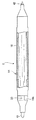
図4及び図5は、本第2実施形態の筆記具Bを示すものである。この実施形態の筆記具Bは、図4及び図5に示すように、筆記具本体となる軸筒14、インキ吸蔵体15、インキ誘導管32、ペン先40、尾栓60とを備えたものであり、上記筆記具Aの実施形態に較べ、軸筒の構成、インキ誘導管の保持構造、中継芯を用いない点などで相違するものであり、その他の構成は基本的に上記第1実施形態と同様である。
本実施形態の筆記具Bは、インキ誘導管32がインキ吸蔵体15からのインキの流入を毛細管作用で流入しやすくするために、細環状となっており、該インキ誘導管30が後部保持体34及び前部保持体35で保持されている点、インキ誘導管30の前端部はペン先40の後端部に嵌入し、インキ誘導管30の後端部はインキ吸蔵体15の前端部に嵌入している点などで上記第1実施形態の筆記具Aと相違するものである。
また、軸筒14は、例えば、上記第1実施形態と同様に熱可塑性樹脂製から構成されるものであり、先端側がテーパー部を有する小径部14aと、大径部14bとが一体となったものであり、該小径部14a内にはペン先40を嵌着する嵌着部14cを有すると共に、大径部10b内は筆記具用インキを含浸した上記第1実施形態と同様のインキ吸蔵体15、インキハジキ層を少なくともインキと接触する面に形成したインキ誘導管32を収容する構造となっている。
更に、軸筒14の大径部14bの先端側は、図4及び図5に示すように、軸筒内を視認できるように上述の光学特性の熱可塑性樹脂から構成された視認部14dを有し、それ以外は別部材又は着色部・装飾部等により非視認部となっている。
4 and 5 show the writing instrument B of the second embodiment. As shown in FIGS. 4 and 5, the writing instrument B according to this embodiment includes a
The writing instrument B of the present embodiment has a narrow ring shape so that the
The
Furthermore, as shown in FIGS. 4 and 5, the distal end side of the large-
このように構成される本第2実施形態の筆記具Bでは、図4及び図5に示すように、インキ吸蔵体20に含浸されたインキは毛細管現象により、インキハジキ層を少なくともインキと接触する面に形成したインキ誘導管32内をとおり、ペン先40に浸透して筆記が可能となる。
この第2実施形態の筆記具Bでは、インキ吸蔵体15に含浸されたインキは常時インキ誘導管32内をとおりペン先40に供給される構造であるので、筆記によりインキ吸蔵体15に含浸されたインキが減少して終了する場合には、インキ誘導管32内のインキの通過が無くなることにより判るものとなる。
すなわち、本実施形態の筆記具Bでは、インキ吸蔵体15からのインキ終了サインを軸筒14に形成した視認部14dを介して上記インキ誘導管32を視認することにより検知することができるものとなる。従って、ぺン先40でのインキのカスレがペン先40での乾燥によるものか、または、インキの消費による本来の終了によるのかを視覚により明確に、かつ簡単に判断することができるものとなる。また、インキ誘導管32には、インキハジキ層31が形成されているので、インキ付着を起こすことなくインキ誘導管内をスムーズに流通することとなる。
In the writing instrument B of the second embodiment configured as described above, as shown in FIGS. 4 and 5, the ink impregnated in the
In the writing instrument B of the second embodiment, since the ink impregnated in the
That is, in the writing instrument B of the present embodiment, the ink end sign from the
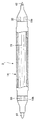
図6は、本発明の第3実施形態を示すものであり、軸筒14内のインキ吸蔵体15に含浸されたインキを軸筒14の両側に設けた筆記部となるアンダーライン用のペン先41、並びに、サインペン用のペン先42に供給するツインタイプの筆記具Cである点でのみ、上記第1実施形態の中継芯20を用いた筆記具A、または、上記第2実施形態の中継芯20を使用しない筆記具Bと相違するものであり、この筆記具Cにはそれぞれ上記第1実施形態の中継芯20を用いた筆記具A、または、上記第2実施形態の中継芯20を使用しない筆記具Bの構成を適用することができる。
この実施形態の筆記具Cでは、インキ吸蔵体15からのインキの供給はペン先41側では図1〜図3又は図4及び図5と同様に、インキ吸蔵体15からのインキが視認性を有すし、インキハジキ層を少なくともインキと接触する面に形成したインキ誘導管30を介して供給されるものであり、ペン先45側ではペン先42の後端部分がインキ吸蔵体15内に嵌入し接触することによりインキ吸蔵体15からのインキが直接供給されるものとなっている。
このツインタイプの筆記具Cでは、インキの消費は各ペン先41、42で行われ、インキ吸蔵体15のインキ終了サインを視認部10bを介してインキハジキ層を少なくともインキと接触する面に形成したインキ誘導管30を視認することにより検知するものである。
FIG. 6 shows a third embodiment of the present invention, and an underline nib serving as a writing portion provided with ink impregnated in the
In the writing instrument C of this embodiment, the ink supplied from the
In this twin-type writing instrument C, ink is consumed by the
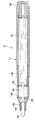
図7は、本発明の第4実施形態を示すものであり、軸筒14内のインキ吸蔵体15に含浸されたインキを軸筒14の両側に設けた筆記部となるアンダーライン用のペン先41、並びに、サインペン用のペン先42に供給するツインタイプの筆記具Dであり、それぞれにインキ誘導管30を設けた点でのみ、上記第1及び第2実施形態の筆記具A,Bと相違するものである。
インキ吸蔵体15からのインキの供給は、ペン先41及び42の両側では図1〜図3又は図4及び図5と同様に、インキ吸蔵体15からのインキが視認性を有する両側に設けたインキ誘導管30、30を介して供給されるものとなっている。
このツインタイプの筆記具Dでは、インキの消費は各ペン先41、42で行われ、インキ吸蔵体15のインキ終了サインを各視認部10bを介してインキハジキ層を少なくともインキと接触する面に形成したインキ誘導管30を視認することにより検知するものである。
なお、軸筒14内に隔壁部を設けて、インキ吸蔵体を収容する部屋を2つ設け、該各部屋に別々のインキ、例えば、アンダーライン用インキ、ボールペン用インキ(ペン先をボールペン用ペン先とする)を吸蔵した各インキ吸蔵体を収容してもよいものである。
FIG. 7 shows a fourth embodiment of the present invention, and an underline nib serving as a writing portion provided with ink impregnated in the
Ink supply from the
In this twin-type writing instrument D, the ink is consumed by the
It should be noted that a partition wall is provided in the
本発明の筆記具は、上記各実施形態1〜4に限定されるものでなく、本発明の要旨を変更しない範囲で種々の形態に変更できることはいうまでもない。
本発明は、軸筒内のインキ吸蔵体に含浸されたインキを筆記部となるペン先に供給する筆記具であって、上記インキ吸蔵体に含浸されたインキは、視認性を有する熱可塑性樹脂で形成された少なくともインキと接する面にインキハジキ層を形成してなるインキ誘導管を介してペン先に供給されると共に、インキ吸蔵体からのインキ終了サインを軸筒に形成した視認部を介して上記インキ誘導管を視認することにより検知できる構造等を要旨とするので、この要旨を変更しない構成は特に限定されるものではなく、各種公知の筆記具構造が採用でき、また、ペン先、インキ種をボールペン、サインペン、マーキングペン、筆ペン、ホワイトバード用マーカーなどの用途などによって変更して好適に各種用途の筆記具に適用することができるものである。
更に、筆記具用インキを修正液、塗布液、化粧品等の液状化粧料等とした塗布具にも適用してもよいものである。
It is needless to say that the writing instrument of the present invention is not limited to the above first to fourth embodiments, and can be changed to various forms without changing the gist of the present invention.
The present invention is a writing instrument for supplying ink impregnated in an ink occlusion body in a shaft cylinder to a pen tip serving as a writing portion, and the ink impregnated in the ink occlusion body is a thermoplastic resin having visibility. The ink is supplied to the pen tip through an ink guide tube formed with an ink repellency layer on at least the surface in contact with the ink, and the ink end sign from the ink occlusion body is formed through the visual recognition portion formed on the shaft cylinder. Since the gist of the structure and the like that can be detected by visually recognizing the ink guide tube, the configuration not changing this gist is not particularly limited, and various known writing instrument structures can be adopted, and the pen tip and ink type can be changed. What can be suitably applied to writing instruments for various purposes, depending on the application such as ballpoint pen, sign pen, marking pen, brush pen, white bird marker, etc. A.
Furthermore, the present invention may be applied to applicators that use ink for writing instruments as liquid cosmetics such as correction liquids, coating liquids, and cosmetics.
次に、本発明を具体的な実施例に基づき更に詳細に説明するが、本発明は下記実施例に限定されるものではない。なお、インキ等の表面張力の測定は、ウィルヘルミー法(協和界面科学社製、CBVP−Z型)により測定し、インキの粘度係数は、回転粘度計(トキメック社製、TV−20L)により測定した。 Next, the present invention will be described in more detail based on specific examples, but the present invention is not limited to the following examples. The surface tension of ink and the like was measured by the Wilhelmy method (manufactured by Kyowa Interface Science Co., Ltd., CBVP-Z type), and the viscosity coefficient of the ink was measured by a rotational viscometer (manufactured by Tokimec Co., Ltd., TV-20L). .
〔実施例1〜16、図1及び図2準拠、ホワイトボード用マーカー〕
下記構成の先軸、後軸、保持部材、インキ吸蔵体、ペン先、インキ組成A〜Cを用い(以上を共通構成とし)、インキハジキ層を少なくともインキと接触する面に形成したインキ誘導管を下記に記載の製造により得られたもの(形状、内径、長さ、流路断面積は共通)を夫々用いて図1及び図2に準拠するホワイトボード用マーカーを作製した。
[Examples 1 to 16, conforming to FIGS. 1 and 2, whiteboard marker]
An ink guide tube having a front shaft, a rear shaft, a holding member, an ink occlusion body, a pen tip, and ink compositions A to C having the following configuration (the above is a common configuration) and having an ink repellent layer formed on at least a surface in contact with ink. Whiteboard markers conforming to FIGS. 1 and 2 were prepared using the products obtained by the production described below (the shape, inner diameter, length, and channel cross-sectional area are common).
(1)先軸10
ポリプロピレン製(全光線透過率約85%、ヘイズ約6%)、大径部(視認部)の長さ10mm(視認部以外は着色層により非視認部となる)、全長36mm
(2)インキ吸蔵体15
ポリエチレンテレフタレート(PET)製の中綿から構成(気孔率80%)、直径12mm、長さ(L)65mm
(3)中継芯
PET製から構成(気孔率60%)、直径2.9mm、長さ22.5mm、後端部分がインキ吸蔵体15に嵌入する長さ(L1)9.5mm
(4)インキ誘導管の共通事項
長さ36mm、インキ流路内体積約89mm3
(5)ペン先
アクリル繊維のスライバー芯から構成(気孔率55%)、長さ15mm
(1)
Made of polypropylene (total light transmittance of about 85%, haze of about 6%), large diameter part (viewing part) length of 10 mm (other than the viewing part becomes non-viewing part by colored layer), total length 36 mm
(2)
Consists of polyethylene terephthalate (PET) batting (porosity 80%), diameter 12mm, length (L) 65mm
(3) Relay core Made of PET (
(4) Common Matters length 36 mm, the ink flow path volume of about 89 mm 3 of ink guiding tube
(5) Pen tip Consists of acrylic fiber sliver core (porosity 55%),
(6)インキ組成A〜C
〔インキ組成A(ホワイトボードマーカー用インキ組成物、全量100重量%)〕
カーボンブラック M−800 4.9重量%
デンカブチラール #−3000−4 4.9重量%
カルボキシル化ポリオキシエチレンラウリルエーテルの
モノエタノールアミン塩 0.1重量%
ポリブチレングリコールジステアレート 11.7重量%
エチルアルコール 63.7重量%
n−プロピルアルコール 14.7重量%
インキの表面張力(25℃)22mN/m、インキの粘度係数(25℃)5.5mPa・s、インキ吸蔵体への含浸量4g
〔インキ組成B(水性ボールペン用インキ組成物、全量100重量%)〕
カーボンブラック MA−100(三菱化学社製) 8.0重量%
グリセリン 5.0重量%
プロピレングリコール 6.0重量%
ジエチレングリコール 6.0重量%
スチレンアクリル樹脂アンモニウム塩 3.0重量%
ノニオン系界面活性剤 スコアロール700(花王社製) 0.1重量%
アミノメチルプロパノール 0.2重量%
1,2−ベンズイソチアゾリン−3−オン
Proxel BMD(ゼネカ社製) 0.1重量%
ベンゾトリアゾール 0.1重量%
精製水 残 部
インキの表面張力(25℃)40mN/m、インキの粘度係数(25℃)5.1mPa・s、インキ吸蔵体への含浸量4g
〔インキ組成C(水性アンダーラインマーカー用インキ組成物、全量100重量%)〕
桃色系蛍光顔料 NKW3007(日本蛍光化学社製) 40重量%
グリセリン 10重量%
ジエチレングリコール 10重量%
1,2−ベンズイソチアゾリン−3−オン
Proxel BMD(ゼネカ社製) 0.1重量%
精製水 残 部
インキの表面張力(25℃)35mN/m、インキの粘度係数(25℃)5.4mPa・s、インキ吸蔵体への含浸量4g
上記構成及び下記より得られたインキハジキ層を少なくともインキと接触する面に形成した各インキ誘導管を用いて図1及び図2に準拠するマーカーAを作製した。
(6) Ink compositions A to C
[Ink composition A (ink composition for whiteboard marker, total amount 100% by weight)]
Carbon black M-800 4.9% by weight
Denkabutyral # -3000-4 4.9% by weight
Monoethanolamine salt of carboxylated polyoxyethylene lauryl ether 0.1% by weight
Polybutylene glycol distearate 11.7% by weight
Ethyl alcohol 63.7% by weight
n-propyl alcohol 14.7% by weight
Ink surface tension (25 ° C.) 22 mN / m, ink viscosity coefficient (25 ° C.) 5.5 mPa · s, impregnation amount into ink occlusion body 4 g
[Ink composition B (water-based ballpoint pen ink composition, 100% by weight in total)]
Carbon black MA-100 (Mitsubishi Chemical Corporation) 8.0% by weight
Glycerin 5.0% by weight
Propylene glycol 6.0% by weight
Diethylene glycol 6.0% by weight
Styrene acrylic resin ammonium salt 3.0% by weight
Nonionic surfactant score roll 700 (manufactured by Kao Corporation) 0.1% by weight
Aminomethylpropanol 0.2% by weight
1,2-benzisothiazolin-3-one Proxel BMD (manufactured by Zeneca) 0.1% by weight
Benzotriazole 0.1% by weight
Purified water balance Ink surface tension (25 ° C.) 40 mN / m, ink viscosity coefficient (25 ° C.) 5.1 mPa · s, impregnation amount into ink occlusion body 4 g
[Ink composition C (ink composition for water-based underline marker, total amount 100% by weight)]
Pink fluorescent pigment NKW3007 (Nippon Fluorochemicals) 40% by weight
1,2-benzisothiazolin-3-one Proxel BMD (manufactured by Zeneca) 0.1% by weight
Purified water balance Ink surface tension (25 ° C.) 35 mN / m, ink viscosity coefficient (25 ° C.) 5.4 mPa · s, impregnation amount into ink occlusion body 4 g
The marker A based on FIG.1 and FIG.2 was produced using each ink guide tube which formed the ink repellency layer obtained from the said structure and the following at least in the surface which contacts ink.
(実施例1)
全光線透過率約85%でヘイズ約6%のPP製インキ誘導管にプラズマ処理を施し、X−31−608−T(オキシウム型:シリコーン20wt%に対して非晶質シリカ粒子を5wt%含有、信越化学工業社製)を2.5%にMCHで希釈したものをディッピング法にて塗布して、溶剤を揮発させた後に60℃の乾燥機中に投入して1昼夜熱処理して得られたインキハジキ層(厚み5μm)を少なくともインキと接触する面に形成したインキ誘導管を用いて図1及び図2に示す筆記具を組み立てた。インキは、上記インキAを用いた。
このように組み立てられた筆記具で筆記すると、良好な筆記描線が得られ、更に筆記を続けるとやがたインキ誘導管の中のインキが無くなり、インキ終了サインを視認できた。このときのインキ消費率は、約70%であった。なお、消費率は、(充填した)初期インキ量W0、消費したインキ量Wとし、消費率=(W/W0)×100により算出した(以下、同様)。
Example 1
A PP ink induction tube having a total light transmittance of about 85% and a haze of about 6% is subjected to plasma treatment, and X-31-608-T (oxynium type: containing 5 wt% of amorphous silica particles relative to 20 wt% of silicone) , Manufactured by Shin-Etsu Chemical Co., Ltd.) diluted to 2.5% with MCH, is applied by dipping, volatilizes the solvent, and then put into a dryer at 60 ° C. and heat treated for one day. The writing instrument shown in FIG. 1 and FIG. 2 was assembled using an ink guide tube having an ink repellent layer (thickness 5 μm) formed on at least the surface in contact with the ink. The ink A was used as the ink.
When writing with the writing tool assembled in this way, a good writing line was obtained, and when writing was continued, the ink in the ink guide tube eventually disappeared, and the ink end sign could be visually recognized. The ink consumption rate at this time was about 70%. The consumption rate was calculated from the initial ink amount W 0 (filled) and the consumed ink amount W, and the consumption rate = (W / W 0 ) × 100 (the same applies hereinafter).
(実施例2)
全光線透過率約90%以上のPEN製インキ誘導管に、X−31−608−T(オキシウム型:シリコーン20wt%に対して非晶質シリカ粒子を5wt%含有、信越化学工業社製)を2.5%にMCHで希釈したものをディッピング法にて塗布して、溶剤を揮発させた後に60℃の乾燥機中に投入して1昼夜熱処理して得られたインキハジキ層(厚み5μm)を少なくともインキと接触する面に形成したインキ誘導管を用いて図1及び図2に示す筆記具を組み立てた。インキは、上記インキAを用いた。
このように組み立てられた筆記具で筆記すると、良好な筆記描線が得られ、更に筆記を続けるとやがたインキ誘導管の中のインキが無くなり、インキ終了サインを視認できた。このときのインキ消費率は、約70%であった。
(Example 2)
X-31-608-T (Oxium type: containing 5 wt% of amorphous silica particles with respect to 20 wt% of silicone, manufactured by Shin-Etsu Chemical Co., Ltd.) on a PEN ink guide tube having a total light transmittance of about 90% or more An ink repellant layer (thickness 5 μm) obtained by applying a solution diluted with MCH to 2.5% by dipping method, volatilizing the solvent, putting it in a dryer at 60 ° C. and heat-treating it for one day. The writing instrument shown in FIGS. 1 and 2 was assembled using an ink guide tube formed on at least the surface in contact with the ink. The ink A was used as the ink.
When writing with the writing tool assembled in this way, a good writing line was obtained, and when writing was continued, the ink in the ink guide tube eventually disappeared, and the ink end sign could be visually recognized. The ink consumption rate at this time was about 70%.
(実施例3)
全光線透過率約85%でヘイズ約6%のPP製インキ誘導管にプラズマ処理を施し、VF−304VC(フッ素樹脂の2wt%溶液、溶剤:CF3CF2CHFCHFCF3、INTスクリーン社製)をそのままディッピング法にて塗布して、溶剤を揮発させた後に80℃の乾燥機中に投入して1昼夜熱処理して得られたインキハジキ層(厚み1μm)を少なくともインキと接触する面に形成したインキ誘導管を用いて図1及び図2に示す筆記具を組み立てた。インキは、上記インキAを用いた。
このように組み立てられた筆記具で筆記すると、良好な筆記描線が得られ、更に筆記を続けるとやがたインキ誘導管の中のインキが無くなり、インキ終了サインを視認できた。このときのインキ消費率は、約70%であった。
(Example 3)
A PP ink guide tube having a total light transmittance of about 85% and a haze of about 6% is subjected to plasma treatment, and VF-304VC (2 wt% solution of fluororesin, solvent: CF 3 CF 2 CHFCHFCF 3 manufactured by INT Screen) Ink formed at least on the surface in contact with the ink, applied by dipping as it is, volatilized from the solvent, put into a dryer at 80 ° C. and heat-treated for a day and night. The writing instrument shown in FIGS. 1 and 2 was assembled using a guide tube. The ink A was used as the ink.
When writing with the writing tool assembled in this way, a good writing line was obtained, and when writing was continued, the ink in the ink guide tube eventually disappeared, and the ink end sign could be visually recognized. The ink consumption rate at this time was about 70%.
(実施例4)
全光線透過率約90%以上のPEN製インキ誘導管に、VF−304VC(フッ素樹脂の2wt%溶液、溶剤:CF3CF2CHFCHFCF3、INTスクリーン社製、以下同様)をそのままディッピング法にて塗布して、溶剤を揮発させた後に60℃の乾燥機中に投入して1昼夜熱処理して得られたインキハジキ層(厚み1μm)を少なくともインキと接触する面に形成したインキ誘導管を用いて図1及び図2に示す筆記具を組み立てた。インキは、上記インキAを用いた。
このように組み立てられた筆記具で筆記すると、良好な筆記描線が得られ、更に筆記を続けるとやがてインキ誘導管の中のインキが無くなり、インキ終了サインを視認できた。このときのインキ消費率は、約70%であった。
(Example 4)
VF-304VC (2 wt% solution of fluororesin, solvent: CF 3 CF 2 CHFCHFCF 3 , manufactured by INT Screen, the same applies below) is directly applied to the PEN ink guide tube having a total light transmittance of about 90% or more by the dipping method. Using an ink guide tube in which an ink repellant layer (thickness 1 μm) obtained by applying and volatilizing the solvent and then putting it in a dryer at 60 ° C. and heat-treating for one day is formed at least on the surface in contact with the ink. The writing instrument shown in FIGS. 1 and 2 was assembled. The ink A was used as the ink.
When writing with the writing tool assembled in this way, a good writing line was obtained, and when the writing was continued, the ink in the ink guide tube eventually disappeared, and the ink end sign could be visually recognized. The ink consumption rate at this time was about 70%.
(実施例5)
全光線透過率90%以上の環状ポリオレフィン製インキ誘導管にプラズマ処理を施し、X−31−608−T(オキシウム型:シリコーン20wt%に対して非晶質シリカ粒子を5wt%含有、信越化学工業社製)を2.5%にMCHで希釈したものをディッピング法にて塗布して、溶剤を揮発させた後に60℃の乾燥機中に投入して1昼夜熱処理して得られたインキハジキ層(厚み5μm)を少なくともインキと接触する面に形成したインキ誘導管を用いて図1及び図2に示す筆記具を組み立てた。インキは、上記インキAを用いた。
このように組み立てられた筆記具で筆記すると、良好な筆記描線が得られ、更に筆記を続けるとやがたインキ誘導管の中のインキが無くなり、インキ終了サインを視認できた。このときのインキ消費率は、約70%であった。
(Example 5)
Plasma treatment is applied to a cyclic polyolefin ink induction tube having a total light transmittance of 90% or more. X-31-608-T (Oxium type: containing 5 wt% of amorphous silica particles relative to 20 wt% of silicone, Shin-Etsu Chemical Co., Ltd.) Ink repellent layer obtained by applying a solution diluted with MCH to 2.5% by dipping method, volatilizing the solvent, and putting it into a dryer at 60 ° C. and heat-treating it all day and night ( The writing instrument shown in FIGS. 1 and 2 was assembled using an ink guide tube having a thickness of 5 μm) formed on at least the surface in contact with the ink. The ink A was used as the ink.
When writing with the writing tool assembled in this way, a good writing line was obtained, and when writing was continued, the ink in the ink guide tube eventually disappeared, and the ink end sign could be visually recognized. The ink consumption rate at this time was about 70%.
(実施例6)
全光線透過率90%以上のポリメチルペンテン製インキ誘導管にコロナ処理を施し、X−31−608−T(オキシウム型:シリコーン20wt%に対して非晶質シリカ粒子を5wt%含有、信越化学工業社製)を2.5%にMCHで希釈したものをディッピング法にて塗布して、溶剤を揮発させた後に60℃の乾燥機中に投入して1昼夜熱処理して得られたインキハジキ層(厚み5μm)を少なくともインキと接触する面に形成したインキ誘導管を用いて図1及び図2に示す筆記具を組み立てた。インキは、上記インキAを用いた。
このように組み立てられた筆記具で筆記すると、良好な筆記描線が得られ、更に筆記を続けるとやがたインキ誘導管の中のインキが無くなり、インキ終了サインを視認できた。このときのインキ消費率は、約70%であった。
(Example 6)
A polymethylpentene ink guide tube having a total light transmittance of 90% or more is subjected to corona treatment, and X-31-608-T (oxynium type: containing 5 wt% of amorphous silica particles relative to 20 wt% of silicone, Shin-Etsu Chemical) An ink repellant layer obtained by applying a solution diluted with MCH to 2.5% by a dipping method, volatilizing the solvent, putting it in a dryer at 60 ° C., and heat-treating it for one day. The writing instrument shown in FIGS. 1 and 2 was assembled using an ink guide tube having a thickness (5 μm) at least on the surface in contact with the ink. The ink A was used as the ink.
When writing with the writing tool assembled in this way, a good writing line was obtained, and when writing was continued, the ink in the ink guide tube eventually disappeared, and the ink end sign could be visually recognized. The ink consumption rate at this time was about 70%.
(実施例7)
全光線透過率90%以上の環状ポリオレフィン製インキ誘導管にプラズマ処理を施し、VF−304VC(INTスクリーン社製)をそのままディッピング法にて塗布して、溶剤を揮発させた後に80℃の乾燥機中に投入して1昼夜熱処理して得られたインキハジキ層(厚み1μm)を少なくともインキと接触する面に形成したインキ誘導管を用いて図1及び図2に示す筆記具を組み立てた。インキは、上記インキAを用いた。
このように組み立てられた筆記具で筆記すると、良好な筆記描線が得られ、更に筆記を続けるとやがたインキ誘導管の中のインキが無くなり、インキ終了サインを視認できた。このときのインキ消費率は、約70%であった。
(Example 7)
Plasma treatment is applied to a cyclic polyolefin ink induction tube having a total light transmittance of 90% or more, VF-304VC (manufactured by INT Screen) is applied as it is by dipping method, and the solvent is volatilized. The writing instrument shown in FIGS. 1 and 2 was assembled using an ink guide tube in which an ink repellent layer (thickness 1 μm) obtained by heat treatment for one day and night was formed at least on the surface in contact with the ink. The ink A was used as the ink.
When writing with the writing tool assembled in this way, a good writing line was obtained, and when writing was continued, the ink in the ink guide tube eventually disappeared, and the ink end sign could be visually recognized. The ink consumption rate at this time was about 70%.
(実施例8)
全光線透過率90%以上のポリメチルペンテン製インキ誘導管にコロナ処理を施し、VF−304VC(INTスクリーン社製)を希釈することなく、そのままディッピング法にて塗布して、溶剤を揮発させた後に60℃の乾燥機中に投入して1昼夜熱処理して得られたインキハジキ層(厚み1μm)を少なくともインキと接触する面に形成したインキ誘導管を用いて図1及び図2に示す筆記具を組み立てた。インキは、上記インキAを用いた。
このように組み立てられた筆記具で筆記すると、良好な筆記描線が得られ、更に筆記を続けるとやがたインキ誘導管の中のインキが無くなり、インキ終了サインを視認できた。このときのインキ消費率は、約70%であった。
(Example 8)
A polymethylpentene ink guide tube having a total light transmittance of 90% or more was subjected to corona treatment, and VF-304VC (manufactured by INT Screen) was applied as it was without being diluted, and the solvent was volatilized. The writing instrument shown in FIG. 1 and FIG. 2 is formed using an ink guide tube in which an ink repellent layer (thickness: 1 μm) obtained after being put into a dryer at 60 ° C. and heat-treated for one day is formed on at least the surface in contact with the ink. Assembled. The ink A was used as the ink.
When writing with the writing tool assembled in this way, a good writing line was obtained, and when writing was continued, the ink in the ink guide tube eventually disappeared, and the ink end sign could be visually recognized. The ink consumption rate at this time was about 70%.
(実施例9)
全光線透過率約85%でヘイズ約6%のPP製インキ誘導管にプラズマ処理を施し、SG−204(ポリシロキサングラフトポリマー、日本触媒社製)を10%にIPA/トルエンの混合液溶媒(配合比1/2)で希釈したものをディッピング法にて塗布して、溶剤を揮発させた後に60℃の乾燥機中に投入して1昼夜熱処理して得られたインキハジキ層(厚み1.5μm)を少なくともインキと接触する面に形成したインキ誘導管を用いて図1及び図2に示す筆記具を組み立てた。インキは、上記インキBを用いた。
このように組み立てられた筆記具で筆記すると、良好な筆記描線が得られ、更に筆記を続けるとやがたインキ誘導管の中のインキが無くなり、インキ終了サインを視認できた。このときのインキ消費率は、約70%であった。
Example 9
A PP ink induction tube having a total light transmittance of about 85% and a haze of about 6% is subjected to plasma treatment, and SG-204 (polysiloxane graft polymer, manufactured by Nippon Shokubai Co., Ltd.) is added to 10% as a mixed solvent of IPA / toluene ( An ink repellant layer (thickness: 1.5 μm) obtained by applying a solution diluted at a blending ratio of 1/2) by dipping method, volatilizing the solvent, putting it in a dryer at 60 ° C. and heat-treating it all day and night The writing instrument shown in FIGS. 1 and 2 was assembled using an ink guide tube formed on at least the surface in contact with the ink. The ink B was used as the ink.
When writing with the writing tool assembled in this way, a good writing line was obtained, and when writing was continued, the ink in the ink guide tube eventually disappeared, and the ink end sign could be visually recognized. The ink consumption rate at this time was about 70%.
(実施例10)
全光線透過率約90%以上のPEN製インキ誘導管に、SG−204(ポリシロキサングラフトポリマー、日本触媒社製)を10%にIPA/トルエンの混合液溶媒(配合比1/2)で希釈したものをディッピング法にて塗布して、溶剤を揮発させた後に60℃の乾燥機中に投入して1昼夜熱処理して得られたインキハジキ層(厚み約10μm)を少なくともインキと接触する面に形成したインキ誘導管を用いて図1及び図2に示す筆記具を組み立てた。インキは、上記インキBを用いた。
このように組み立てられた筆記具で筆記すると、良好な筆記描線が得られ、更に筆記を続けるとやがたインキ誘導管の中のインキが無くなり、インキ終了サインを視認できた。このときのインキ消費率は、約70%であった。
(Example 10)
In a PEN ink guide tube with a total light transmittance of about 90% or more, SG-204 (polysiloxane graft polymer, manufactured by Nippon Shokubai Co., Ltd.) is diluted to 10% with a mixed solvent of IPA / toluene (mixing ratio 1/2). The ink repellant layer (thickness: about 10 μm) obtained by applying the product by dipping method, volatilizing the solvent, putting it in a dryer at 60 ° C. and heat-treating it for a day and night is at least on the surface in contact with the ink. The writing instrument shown in FIG.1 and FIG.2 was assembled using the formed ink guide tube. The ink B was used as the ink.
When writing with the writing tool assembled in this way, a good writing line was obtained, and when writing was continued, the ink in the ink guide tube eventually disappeared, and the ink end sign could be visually recognized. The ink consumption rate at this time was about 70%.
(実施例11)
全光線透過率約85%、ヘイズ約6%のPP製インキ誘導管にプラズマ処理を施し、プラマーとしてCT−P10(有効成分15%、旭硝子社製)を2%に希釈したものを塗布して、60℃で3時間乾燥させた。その後、No.309(フッ素樹脂の15wt%溶液、溶剤:イソへキサン/アセトン混合溶媒、INTスクリーン社製)をそのままディッピング法にて塗布して、溶剤を揮発させた後に80℃の乾燥機中に投入して1昼夜熱処理して得られたインキハジキ層(厚み20μm)を少なくともインキと接触する面に形成したインキ誘導管を用いて図1及び図2に示す筆記具を組み立てた。インキは、上記インキCを用いた。
このように組み立てられた筆記具で筆記すると、良好な筆記描線が得られ、更に筆記を続けるとやがたインキ誘導管の中のインキが無くなり、インキ終了サインを視認できた。このときのインキ消費率は、約70%であった。
(Example 11)
Apply a plasma treatment to a PP ink induction tube with a total light transmittance of about 85% and a haze of about 6%, and apply a CT-P10 (
When writing with the writing tool assembled in this way, a good writing line was obtained, and when writing was continued, the ink in the ink guide tube eventually disappeared, and the ink end sign could be visually recognized. The ink consumption rate at this time was about 70%.
(実施例12)
全光線透過率約90%以上のPEN製インキ誘導管に、JS−025(ポリシロキサングラフトアクリル樹脂、日本ペイント社製)をn−PAで5%に希釈したものをディッピング法にて塗布して、溶剤を揮発させた後に80℃の乾燥機中に投入して1昼夜熱処理して得られたインキハジキ層(厚み1μm)を少なくともインキと接触する面に形成したインキ誘導管を用いて図1及び図2に示す筆記具を組み立てた。インキは、上記インキBを用いた。
このように組み立てられた筆記具で筆記すると、良好な筆記描線が得られ、更に筆記を続けるとやがたインキ誘導管の中のインキが無くなり、インキ終了サインを視認できた。このときのインキ消費率は、約70%であった。
Example 12
A PEN ink guide tube having a total light transmittance of about 90% or more was coated with JS-025 (polysiloxane graft acrylic resin, manufactured by Nippon Paint Co., Ltd.) diluted to 5% with n-PA by the dipping method. 1 and FIG. 1 using an ink induction tube in which an ink repellent layer (thickness 1 μm) obtained by volatilizing the solvent and then putting it in a dryer at 80 ° C. and heat-treating for one day is formed on at least the surface in contact with the ink. The writing instrument shown in FIG. 2 was assembled. The ink B was used as the ink.
When writing with the writing tool assembled in this way, a good writing line was obtained, and when writing was continued, the ink in the ink guide tube eventually disappeared, and the ink end sign could be visually recognized. The ink consumption rate at this time was about 70%.
(実施例13)
全光線透過率90%以上の環状ポリオレフィン製インキ誘導管にプラズマ処理を施し、JS−025(ポリシロキサングラフトアクリル樹脂、日本ペイント社製)をn−PAで5%に希釈したものをディッピング法にて塗布して、溶剤を揮発させた後に60℃の乾燥機中に投入して1昼夜熱処理して得られたインキハジキ層(厚み1μm)を少なくともインキと接触する面に形成したインキ誘導管を用いて図1及び図2に示す筆記具を組み立てた。インキは、上記インキBを用いた。
このように組み立てられた筆記具で筆記すると、良好な筆記描線が得られ、更に筆記を続けるとやがたインキ誘導管の中のインキが無くなり、インキ終了サインを視認できた。このときのインキ消費率は、約70%であった。
(Example 13)
Plasma treatment is applied to a cyclic polyolefin ink induction tube having a total light transmittance of 90% or more, and JS-025 (polysiloxane graft acrylic resin, manufactured by Nippon Paint Co., Ltd.) is diluted to 5% with n-PA. Using an ink guide tube in which an ink repellant layer (thickness 1 μm) obtained by evaporating the solvent, volatilizing the solvent, and putting it into a dryer at 60 ° C. and heat-treating for one day is formed on at least the surface in contact with the ink. The writing instrument shown in FIGS. 1 and 2 was assembled. The ink B was used as the ink.
When writing with the writing tool assembled in this way, a good writing line was obtained, and when writing was continued, the ink in the ink guide tube eventually disappeared, and the ink end sign could be visually recognized. The ink consumption rate at this time was about 70%.
(実施例14)
全光線透過率90%以上のポリメチルペンテン製インキ誘導管にオゾン処理を施し、INT−304VC(フッ素樹脂の2wt%溶液、溶剤:CF3CF2CHFCHFCF3、INTスクリーン社製)をそのままディッピング法にて塗布して、溶剤を揮発させた後に60℃の乾燥機中に投入して1昼夜熱処理して得られたインキハジキ層(厚み1μm)を少なくともインキと接触する面に形成したインキ誘導管を用いて図1及び図2に示す筆記具を組み立てた。インキは、上記インキCを用いた。
このように組み立てられた筆記具で筆記すると、良好な筆記描線が得られ、更に筆記を続けるとやがたインキ誘導管の中のインキが無くなり、インキ終了サインを視認できた。このときのインキ消費率は、約70%であった。
(Example 14)
A polymethylpentene ink guide tube with a total light transmittance of 90% or more is subjected to ozone treatment, and INT-304VC (2 wt% solution of fluororesin, solvent: CF 3 CF 2 CHFCHFCF 3 , manufactured by INT Screen) is used as it is. An ink guide tube having an ink repellent layer (thickness: 1 μm) formed on at least the surface in contact with the ink is applied by coating, volatilizing the solvent, and then put into a dryer at 60 ° C. and heat-treated for one day. The writing instrument shown in FIG.1 and FIG.2 was assembled using it. The ink C was used as the ink.
When writing with the writing tool assembled in this way, a good writing line was obtained, and when writing was continued, the ink in the ink guide tube eventually disappeared, and the ink end sign could be visually recognized. The ink consumption rate at this time was about 70%.
(実施例15)
全光線透過率約90%のPP製インキ誘導管にプラズマ処理を施し、次いで、オゾン雰囲気下にしてTEOS(テトラエトキシシラン)を同時に雰囲気下に流し、PPの表面にシリカ膜を構築させた。その後、X−31−608−T(オキシウム型:シリコーン20wt%に対して非晶質シリカ粒子を5wt%含有、信越化学工業社製)を2.5%にMCHで希釈したものをディッピング法にて塗布して、溶剤を揮発させた後に60℃の乾燥機中に投入して1昼夜熱処理して得られたインキハジキ層(厚み5μm)を少なくともインキと接触する面に形成したインキ誘導管を用いて図1及び図2に示す筆記具を組み立てた。インキは、上記インキAを用いた。
このように組み立てられた筆記具で筆記すると、良好な筆記描線が得られ、更に筆記を続けるとやがたインキ誘導管の中のインキが無くなり、インキ終了サインを視認できた。このときのインキ消費率は、約70%であった。
(Example 15)
A PP ink guide tube having a total light transmittance of about 90% was subjected to plasma treatment, and then TEOS (tetraethoxysilane) was simultaneously flowed under an ozone atmosphere to form a silica film on the surface of PP. Thereafter, X-31-608-T (Oxium type: containing 5 wt% of amorphous silica particles with respect to 20 wt% of silicone, manufactured by Shin-Etsu Chemical Co., Ltd.) diluted to 2.5% with MCH is used as a dipping method. Using an ink guide tube in which an ink repellant layer (thickness 5 μm) obtained by evaporating the solvent, volatilizing the solvent and then putting it into a dryer at 60 ° C. and heat-treating for one day is formed on at least the surface in contact with the ink. The writing instrument shown in FIGS. 1 and 2 was assembled. The ink A was used as the ink.
When writing with the writing tool assembled in this way, a good writing line was obtained, and when writing was continued, the ink in the ink guide tube eventually disappeared, and the ink end sign could be visually recognized. The ink consumption rate at this time was about 70%.
(実施例16)
全光線透過率約90%以上のPEN製インキ誘導管に、エチルシリケート40(エチルシリケート/コルコート社製)をn−PAで10%濃度に希釈したものを塗布して、300nm以下の紫外線を照射してシリカ膜を構築させた後、X−31−608−T(脱オキシウム型:シリコーン20wt%に対して非晶質シリカ粒子を5wt%含有、信越化学工業社製)を2.5%にMCHで希釈したものをディッピング法にて塗布して、溶剤を揮発させた後に60℃の乾燥機中に投入して1昼夜熱処理して得られたインキハジキ層(厚み5μm)を少なくともインキと接触する面に形成したインキ誘導管を用いて図1及び図2に示す筆記具を組み立てた。インキは、上記インキAを用いた。
このように組み立てられた筆記具で筆記すると、良好な筆記描線が得られ、更に筆記を続けるとやがたインキ誘導管の中のインキが無くなり、インキ終了サインを視認できた。このときのインキ消費率は、約70%であった。
(Example 16)
A PEN ink guide tube having a total light transmittance of about 90% or more is coated with ethyl silicate 40 (ethyl silicate / Colcoat Co.) diluted to 10% with n-PA and irradiated with ultraviolet rays of 300 nm or less. After the silica film was constructed, X-31-608-T (deoxynium type: containing 5 wt% of amorphous silica particles relative to 20 wt% of silicone, manufactured by Shin-Etsu Chemical Co., Ltd.) to 2.5% An ink repellent layer (thickness: 5 μm) obtained by applying a solution diluted with MCH by dipping method, volatilizing the solvent, putting it in a dryer at 60 ° C., and heat-treating it for one day and night contacts at least the ink. The writing implement shown in FIG.1 and FIG.2 was assembled using the ink guide tube formed in the surface. The ink A was used as the ink.
When writing with the writing tool assembled in this way, a good writing line was obtained, and when writing was continued, the ink in the ink guide tube eventually disappeared, and the ink end sign could be visually recognized. The ink consumption rate at this time was about 70%.
〔実施例17〜18、図4及び図5準拠、サインペン〕
下記構成の軸筒、インキ吸蔵体、ペン先、上記インキ組成Cを用い(以上を共通構成とし)、インキハジキ層を少なくともインキと接触する面に形成したインキ誘導管を下記に記載の製造により得られたもの(形状、内径、長さ、流路断面積は共通)を夫々用いて図4及び図5に準拠するサインペンを作製した。
[Examples 17 to 18, based on FIGS. 4 and 5, sign pen]
Using the shaft cylinder, ink occlusion body, nib, and ink composition C described above (the above is the common structure), an ink guide tube having an ink repellent layer formed on at least the surface in contact with the ink is obtained by the production described below. The sign pens conforming to FIGS. 4 and 5 were produced using the obtained ones (the shape, the inner diameter, the length, and the channel cross-sectional area are common).
(1)軸筒14
ポリプロピレン製(全光線透過率約85%、ヘイズ約6%)、視認部の長さ15mm(視認部以外は着色層により非視認部となる)、全長120mm
(2)インキ吸蔵体15
ポリエチレンテレフタレート製の中綿から構成(気孔率80%)、直径9mm、長さ60mm
(3)インキ誘導管の共通事項
長さ36mm、内径3.1mm、インキ流路内体積:約89mm3、後端部分がインキ吸蔵体15に嵌入する長さ9.5mm
(4)ペン先
アクリル繊維のスライバー芯から構成(気孔率55%)、長さ15mm
(1)
Made of polypropylene (total light transmittance of about 85%, haze of about 6%), length of
(2)
Consists of polyethylene terephthalate batting (porosity 80%), diameter 9mm, length 60mm
(3) Common items of the ink guide tube 36 mm in length, 3.1 mm in inner diameter, volume in the ink flow path: about 89 mm 3 , length 9.5 mm in which the rear end portion is fitted into the
(4) Pen tip Consists of acrylic fiber sliver core (porosity 55%),
上記構成及び下記より得られたインキハジキ層を少なくともインキと接触する面に形成した各インキ誘導管を用いて図4及び図5に準拠するサインペンBを作製した。 The sign pen B based on FIG.4 and FIG.5 was produced using each ink guide tube which formed the ink repellent layer obtained from the said structure and the following at least in the surface which contacts with ink.
(実施例17)
全光線透過率約85%でヘイズ約6%のPP製インキ誘導管にプラズマ処理を施し、X−31−608−T(オキシウム型:シリコーン20wt%に対して非晶質シリカ粒子を5wt%含有、信越化学工業社製)を2.5%にMCHで希釈したものをディッピング法にて塗布して、溶剤を揮発させた後に80℃の乾燥機中に投入して1昼夜熱処理して得られたインキハジキ層(厚み5μm)を少なくともインキと接触する面に形成したインキ誘導管を用いて図4及び図5に示すサインペンを組み立てた。インキは、上記インキCを用いた。
このように組み立てられた筆記具で筆記すると、良好な筆記描線が得られ、更に筆記を続けるとやがたインキ誘導管の中のインキが無くなり、インキ終了サインを視認できた。このときのインキ消費率は、約70%であった。
(Example 17)
A PP ink induction tube having a total light transmittance of about 85% and a haze of about 6% is subjected to plasma treatment, and X-31-608-T (oxynium type: containing 5 wt% of amorphous silica particles relative to 20 wt% of silicone) , Manufactured by Shin-Etsu Chemical Co., Ltd.) diluted with MCH to 2.5% by dipping method, volatilizes the solvent, and then put into an oven at 80 ° C and heat treated for one day. The sign pen shown in FIG. 4 and FIG. 5 was assembled using an ink guide tube having an ink repellent layer (thickness 5 μm) formed on at least the surface in contact with the ink. The ink C was used as the ink.
When writing with the writing tool assembled in this way, a good writing line was obtained, and when writing was continued, the ink in the ink guide tube eventually disappeared, and the ink end sign could be visually recognized. The ink consumption rate at this time was about 70%.
(実施例18)
全光線透過率約90%以上のPEN製インキ誘導管に、X−31−608−T(オキシウム型:シリコーン20wt%に対して非晶質シリカ粒子を5wt%含有、信越化学工業社製)を2.5%にMCHで希釈したものをディッピング法にて塗布して、溶剤を揮発させた後に60℃の乾燥機中に投入して1昼夜熱処理して得られたインキハジキ層(厚み5μm)を少なくともインキと接触する面に形成したインキ誘導管を用いて図4及び図5に示すサインペンを組み立てた。インキは、上記インキCを用いた。
このように組み立てられた筆記具で筆記すると、良好な筆記描線が得られ、更に筆記を続けるとやがたインキ誘導管の中のインキが無くなり、インキ終了サインを視認できた。このときのインキ消費率は、約70%であった。
(Example 18)
X-31-608-T (Oxium type: containing 5 wt% of amorphous silica particles with respect to 20 wt% of silicone, manufactured by Shin-Etsu Chemical Co., Ltd.) on a PEN ink guide tube having a total light transmittance of about 90% or more An ink repellant layer (thickness 5 μm) obtained by applying a solution diluted with MCH to 2.5% by dipping method, volatilizing the solvent, putting it in a dryer at 60 ° C. and heat-treating it for one day. The sign pen shown in FIGS. 4 and 5 was assembled using an ink guide tube formed on at least the surface in contact with the ink. The ink C was used as the ink.
When writing with the writing tool assembled in this way, a good writing line was obtained, and when writing was continued, the ink in the ink guide tube eventually disappeared, and the ink end sign could be visually recognized. The ink consumption rate at this time was about 70%.
A 筆記具
10 先軸
11 後軸
12 軸筒
15 インキ吸蔵体
20 中継芯
30 インキ誘導管
31 インキハジキ層
40 ペン先
A
Claims (13)
Priority Applications (1)
| Application Number | Priority Date | Filing Date | Title |
|---|---|---|---|
| JP2003314559A JP4265760B2 (en) | 2003-09-05 | 2003-09-05 | Writing instrument |
Applications Claiming Priority (1)
| Application Number | Priority Date | Filing Date | Title |
|---|---|---|---|
| JP2003314559A JP4265760B2 (en) | 2003-09-05 | 2003-09-05 | Writing instrument |
Publications (2)
| Publication Number | Publication Date |
|---|---|
| JP2005081627A JP2005081627A (en) | 2005-03-31 |
| JP4265760B2 true JP4265760B2 (en) | 2009-05-20 |
Family
ID=34415116
Family Applications (1)
| Application Number | Title | Priority Date | Filing Date |
|---|---|---|---|
| JP2003314559A Expired - Fee Related JP4265760B2 (en) | 2003-09-05 | 2003-09-05 | Writing instrument |
Country Status (1)
| Country | Link |
|---|---|
| JP (1) | JP4265760B2 (en) |
Families Citing this family (1)
| Publication number | Priority date | Publication date | Assignee | Title |
|---|---|---|---|---|
| JP4883949B2 (en) * | 2005-07-14 | 2012-02-22 | 三菱鉛筆株式会社 | Writing instrument |
-
2003
- 2003-09-05 JP JP2003314559A patent/JP4265760B2/en not_active Expired - Fee Related
Also Published As
| Publication number | Publication date |
|---|---|
| JP2005081627A (en) | 2005-03-31 |
Similar Documents
| Publication | Publication Date | Title |
|---|---|---|
| CN1652948B (en) | writing utensils | |
| CN102971156B (en) | writing utensils | |
| TWI478824B (en) | Ball point pen and writing instrument set | |
| CA2437806C (en) | Marker pens | |
| JP2019214216A (en) | Writing implement | |
| JP4620363B2 (en) | Contents visible writing instrument member and writing instrument | |
| JP4817767B2 (en) | Writing instrument | |
| JP4265760B2 (en) | Writing instrument | |
| JP7158203B2 (en) | Applicator | |
| JP2020073349A (en) | Writing instrument | |
| JP2004042263A (en) | Writing implement | |
| JP4744829B2 (en) | Writing instrument | |
| JP3732163B2 (en) | Writing instrument | |
| JP2001287493A (en) | Writing implement | |
| JP6902357B2 (en) | Painter | |
| JP3474875B2 (en) | writing implements | |
| JP2019135093A (en) | Pen tip and writing instrument with the pen tip | |
| JP3474875B6 (en) | Writing implement | |
| JP3838960B2 (en) | Ink container for writing instruments | |
| JP2007021822A (en) | Ink refill container for writing instruments | |
| JP2004066479A (en) | Writing implement | |
| JP2004066476A (en) | Ink storage member for writing implements | |
| JP7224136B2 (en) | writing instrument | |
| CN2776690Y (en) | Marking pen | |
| JP2023095978A (en) | writing instrument |
Legal Events
| Date | Code | Title | Description |
|---|---|---|---|
| A621 | Written request for application examination |
Free format text: JAPANESE INTERMEDIATE CODE: A621 Effective date: 20060830 |
|
| A977 | Report on retrieval |
Free format text: JAPANESE INTERMEDIATE CODE: A971007 Effective date: 20090129 |
|
| TRDD | Decision of grant or rejection written | ||
| A01 | Written decision to grant a patent or to grant a registration (utility model) |
Free format text: JAPANESE INTERMEDIATE CODE: A01 Effective date: 20090210 |
|
| A01 | Written decision to grant a patent or to grant a registration (utility model) |
Free format text: JAPANESE INTERMEDIATE CODE: A01 |
|
| A61 | First payment of annual fees (during grant procedure) |
Free format text: JAPANESE INTERMEDIATE CODE: A61 Effective date: 20090210 |
|
| R150 | Certificate of patent or registration of utility model |
Ref document number: 4265760 Country of ref document: JP Free format text: JAPANESE INTERMEDIATE CODE: R150 Free format text: JAPANESE INTERMEDIATE CODE: R150 |
|
| FPAY | Renewal fee payment (event date is renewal date of database) |
Free format text: PAYMENT UNTIL: 20120227 Year of fee payment: 3 |
|
| FPAY | Renewal fee payment (event date is renewal date of database) |
Free format text: PAYMENT UNTIL: 20150227 Year of fee payment: 6 |
|
| R250 | Receipt of annual fees |
Free format text: JAPANESE INTERMEDIATE CODE: R250 |
|
| R250 | Receipt of annual fees |
Free format text: JAPANESE INTERMEDIATE CODE: R250 |
|
| R250 | Receipt of annual fees |
Free format text: JAPANESE INTERMEDIATE CODE: R250 |
|
| R250 | Receipt of annual fees |
Free format text: JAPANESE INTERMEDIATE CODE: R250 |
|
| LAPS | Cancellation because of no payment of annual fees |