JP4265740B2 - Cutter base for automatic stringer - Google Patents
Cutter base for automatic stringer Download PDFInfo
- Publication number
- JP4265740B2 JP4265740B2 JP2003015005A JP2003015005A JP4265740B2 JP 4265740 B2 JP4265740 B2 JP 4265740B2 JP 2003015005 A JP2003015005 A JP 2003015005A JP 2003015005 A JP2003015005 A JP 2003015005A JP 4265740 B2 JP4265740 B2 JP 4265740B2
- Authority
- JP
- Japan
- Prior art keywords
- string
- cutter
- presser
- knot
- base
- Prior art date
- Legal status (The legal status is an assumption and is not a legal conclusion. Google has not performed a legal analysis and makes no representation as to the accuracy of the status listed.)
- Expired - Lifetime
Links
- 210000003323 beak Anatomy 0.000 claims description 20
- 238000000034 method Methods 0.000 claims description 8
- 238000010586 diagram Methods 0.000 description 7
- 230000015572 biosynthetic process Effects 0.000 description 5
- 238000004804 winding Methods 0.000 description 4
- 230000002159 abnormal effect Effects 0.000 description 1
- 230000005856 abnormality Effects 0.000 description 1
- 230000000694 effects Effects 0.000 description 1
- 230000007246 mechanism Effects 0.000 description 1
- 125000006850 spacer group Chemical group 0.000 description 1
Images
Landscapes
- Basic Packing Technique (AREA)
Description
【0001】
【発明の属する技術分野】
本発明は、物品に紐を巻き掛けし、結び目を作って結束する自動紐掛機(自動結束機ともいう。)に関し、特に、紐の結び目形成を補助し、切断を行う自動紐掛機用カッター台(以下、単にカッター台ともいう。)の改良に関する。
【0002】
【従来の技術】
自動紐掛機は、被結束物である物品に紐掛けを行い、結び目を作る一連の作業を自動的に行う装置である。なお、以下では、本発明の主題である結び目の形成について説明し、被結束物への紐掛け等、自動紐掛機の他の機構・動作についての説明は省略する。
【0003】
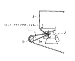
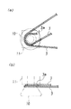
図4は、一連の自動工程の中で、前回の紐掛け作業を完了後に、次の紐掛け工程の途中まで進捗した状態を示している。図4では、紐3が被結束物1に巻き掛けられており、前回切断された紐の紐端部3aが紐押え10に押えられて、かつ、結び目形成用のクチバシ2に巻き付けられた状態を示している。なお、紐押え10は、後述のカッター台の一部材であり、ここでは図示の簡単のため紐押え10のみを示している。
【0004】
この後、結び目形成のため、2本の紐3をクチバシ2で挟み込み、クチバシ2を後退させてクチバシ2に巻き付けた紐輪から抜くように引き込んで結び目を形成する。ここで、クチバシ2が後退し始めるとほぼ同時に、カッター台に具備してなるカッター(ここでは図示しない。)が作動し、長い方の紐をナイフでカットし、同時に紐押え10から紐端部3aを引き抜いて結び目を完成させる。なお、図5に、紐3の紐端部3aを紐押え10と押え台11で挟み込み、かつ、他方の側の紐3を紐押え10に巻き付けた状態を模式的に示す。
【0005】
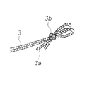
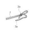
以上のようにして形成した正常な結び目を2本結びとよぶ(図8参照)。なお、図8において3bは紐3の結び目を示す。
自動紐掛機による紐の結束については、例えば、特許文献1等に詳細の開示がある。
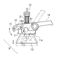
図6は、上述の紐押え10を具備してなる従来のカッター台9の動作を説明する模式図である。カッター台9には、紐を挟み込み、また、巻き付ける機能を有する紐押え10と押え台11が具備され、また、結び目形成後に一方の紐をナイフ15で切断し、他方の挟み込んだ方の紐をカッター溝14a で引っ掛けて引き抜く機能を有するカッター14が具備されてなる。なお、16はナイフ押えである。
【0006】
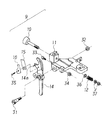
図6において、紐押え10は紐押えばね12で押え台11の押え面11a に押えつけられ、紐押えレバー13を作動させることで紐の一端を挟み込むことができる(図5参照)。また、カッター14を駆動させることで、ナイフ15での紐の切断とカッター溝14a で紐を引っ掛けての引き抜きを行わせることができる。図7は、このカッター台9の要部組立図である。
【0007】
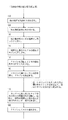
次に、図10に示すフローに基づき、自動紐掛機の結び目形成工程について説明する。なお、図10のフローは、結び目形成の要部工程のみを抜き出して説明するものである。また、以下の説明において、既に説明した部材と同一の部材には、同一の番号を付している。
まず、前回の紐掛け工程完了後、切断された紐3の紐端部3aを紐押え10で挟み込む(110 )。そして、紐3を被結束物1に巻き付け(120 )、紐3の巻き終わり部を紐押え10に引っ掛けて巻く(130 )。次に、紐押え10に巻かれた2本の紐3をクチバシ2に差し込み(140 )、クチバシ2を回転しながら2本の紐3をクチバシ2に巻き付けてくわえ込む(150 )。そして、クチバシ2に紐3をくわえ、クチバシ2に環になっている紐3を押えながら、クチバシ2を後退させる(160 )。
【0008】
以上の一連の工程で、クチバシ2にくわえられた紐3は環の中をくぐって引き込まれ、環はクチバシ2を抜け出て結ばれることになる。そして、カッター14に取り付けたナイフ15で巻き終わり部側の紐3を切断し、同時に、端部を紐押え10に挟み込んだ側の紐(紐端部3a)をカッター溝14a に引っ掛けて引き抜き(170 )、最後に、クチバシ2にくわえた紐3を放し(180 )、2本結びの結び目を完成させる。
【0009】
【特許文献1】
特公昭55-9325 号公報
【0010】
【発明が解決しようとする課題】
ところで、カッター台はその調整が難しく、紐押えで紐を押えるバネ圧が適正でなかったり、また、紐押えの作動部にわずかでも異常があったりすると、挟み込んでいる紐端部が結び目を形成する前に抜けてしまい、しっかりとした正常な結び目が形成されなくなる。また、最悪の場合には、図9に示すような1本結びの状態となる。1本結びの場合、結び目3bは一応形成されており、一見すると結ばれているようにも見えるが、実際には紐端部3a側が結ばれていないため、わずかの力で抜けてしまい、紐がほどけてしまうことになる。
【0011】
本発明は、挟み込んでいる紐端部が結び目を形成する前に容易に抜けることのないようにすることで紐の結び目形成をより確実なものとすることを可能とした自動紐掛機用カッター台を提供するものである。
【0012】
【課題を解決するための手段】
本発明は、2本結びの結び目を完成させるために用いる自動紐掛機用カッター台であって、一対の紐押え(10)と押え台(11)を具備し、該一対の紐押え( 10 )と押え台( 11 )とを用い、前回の紐掛け工程完了後、切断された他方の紐の紐端部を該一対の紐押え( 10 )と押え台( 11 )間に挟み込むこと、そして、被結束物に巻き掛けた一方の紐を該紐押え( 10 )の周りに巻き付けることを行い、次いで結び目形成用のクチバシに2本の紐をくわえ、2本結びの結び目を形成する工程にて、被結束物に巻き掛けた一方の紐をナイフ(15)で切断し、前回切断された他方の挟み込んだ方の紐をカッター溝(14a )で引っ掛けて引き抜く機能を有するカッター(14)を具備し、最後に、前記クチバシにくわえた2本の紐を放し、2本結びの結び目を完成させるに際し、前記押え台(11)のカッター(14)を具備してなる側の側面に、2本結びの結び目を形成する前に2本の紐を引っ掛け、そのうちの前回切断された他方の紐の摩擦抵抗が増し、たとえ紐押え( 10 )での紐の押え方が弱い場合であっても、一対の紐押え( 10 )と押え台( 11 )間から他方の紐の紐端部が抜けてしまうのを防止できる紐掛けフック(5)を付設してなることを特徴とする自動紐掛機用カッター台によって上記課題を解決した。
【0013】
また、本発明は、前記紐掛けフック(5)の紐掛け位置(5a)が前記押え台(11)の押え面(11a )と段差(d)を有してなり、かつ、前記紐掛けフック(5)と前記押え台(11)のカッター(14)を具備してなる側の側面の間に間隙を有するように前記紐掛けフック(5)を配置することを好適とするものである。
【0014】
【発明の実施の形態】
本発明の自動紐掛機用カッター台の好適な実施の形態を図1〜3に基づいて説明する。なお、図6、図7において既に説明した従来のカッター台9を構成する同一の部材には同一の番号を付し、再度の説明を省略する。
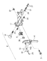
図2の組立図に示すように、本発明のカッター台8では、押え台11のカッター14を具備してなる側の側面に、紐を引っ掛ける紐掛けフック5を付設してなることを特徴とする。
【0015】
この紐掛けフック5で紐を引っ掛けることで、紐の摩擦抵抗が増し、たとえ紐押え10での紐の押え方が弱い場合であっても、紐が抜けてしまうことを防止できる。なお、紐は、単に引っ掛けているだけであり、カッター14のカッター溝14a で紐を引き抜くことに何ら支障がないことは言うまでもない。
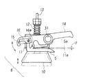
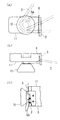
図1は、本発明のカッター台8の模式図であり、紐掛けフック5が押え台11とカッター14の間に介装されている。ここで、紐掛けフック5の紐を引っ掛ける紐掛け位置5aは、押え台11の押え面11a と段差dを有するように配置することを好適とする。また、その場合、図3に示すように、押え台11の側面とカッター14の間には、紐が通るだけの間隙6を設けておく。この間隙6は、押え台11を加工して設ければよい。また、スペーサを押え台11の側面とカッター14の間に介装してもよいし、紐掛けフック5を加工して設けることも可能である。
【0016】
このように紐掛けフック5を配することで、紐押え10と押え台11に挟み込まれた紐3は、押え台11の角と紐掛けフック5に引っ掛けられることになり、それぞれの箇所で摩擦抵抗を生じて容易に抜けることがなくなる。
ここで、本発明者は、紐押え10に係設してなる紐押えばね12の強さを従来操業時の7割程度としても結び目形成時に紐が抜けてしまうトラブルが発生しないことを確認した。すなわち、本発明によって、紐押えばね12の強さ調整における許容範囲を大幅に拡大することができ、カッター台の調整を容易に行うことができるようになった。
【0017】
【発明の効果】
本発明の自動紐掛機用カッター台を使用することで、カッター台の調整作業を容易にし、また、自動紐掛機による結び目形成の信頼性を大幅に向上することができた。
【図面の簡単な説明】
【図1】本発明の自動紐掛機用カッター台の模式図である。
【図2】本発明の自動紐掛機用カッター台の要部組立図である。
【図3】本発明の自動紐掛機用カッター台の紐押えに紐が巻き付いた様子を示す要部模式図であり、(a)は正面図、(b)は平面図、(c)は側面図を示す。
【図4】被結束物への紐掛けの様子を説明する模式図である。
【図5】紐押えに紐が巻き付いた様子を示す模式図である。
【図6】従来の自動紐掛機用カッター台の模式図である。
【図7】図6に示す従来の自動紐掛機用カッター台の要部組立図である。
【図8】正常な紐の結び目(2本結び)の例を示す斜視図である。
【図9】異常な紐の結び目(1本結び)の一例を示す斜視図である。
【図10】自動紐掛機の結び目形成工程について説明するフロー図である。
【符号の説明】
1 被結束物(物品)
2 クチバシ(結節ピーク)
3 紐
3a 紐端部
3b 結び目
5 紐掛けフック
5a 紐掛け位置
5b 紐ガイド部
6 間隙
8、9 自動紐掛機用カッター台(カッター台)
10 紐押え
11 押え台
11a 押え面
12 紐押えばね
13 紐押えレバー
14 カッター
14a カッター溝
15 ナイフ
16 ナイフ押え
31 カッター軸ボルト
32、34、37 ナット
33、35、38 ビス
36 座金
d 段差[0001]
BACKGROUND OF THE INVENTION
The present invention relates to an automatic stringing machine (also referred to as an automatic binding machine) that winds a string around an article, and binds it by making a knot, and particularly for an automatic stringing machine that assists in forming a knot of a string and performs cutting. The present invention relates to improvement of a cutter table (hereinafter also simply referred to as a cutter table).
[0002]
[Prior art]
An automatic strapping machine is a device that automatically performs a series of operations for tying a knot and tying an article that is an object to be bound. In the following, the formation of the knot, which is the subject of the present invention, will be described, and description of other mechanisms and operations of the automatic tying machine, such as tying the objects to be bound, will be omitted.
[0003]
FIG. 4 shows a state in which, in a series of automatic processes, after the previous tying operation is completed, the process has progressed to the middle of the next tying process. In FIG. 4, the
[0004]
Thereafter, two
[0005]
The normal knot formed as described above is called a double knot (see FIG. 8). In FIG. 8, 3b indicates the knot of the
For example, Japanese Patent Application Laid-Open No. H10-133707 discloses details of string binding by an automatic stringer.
FIG. 6 is a schematic diagram for explaining the operation of the
[0006]
In FIG. 6, the
[0007]
Next, based on the flow shown in FIG. 10, the knot forming process of the automatic stringer will be described. Note that the flow of FIG. 10 is described by extracting only the main process of knot formation. Moreover, in the following description, the same number is attached | subjected to the member same as the already demonstrated member.
First, after completion of the previous stringing step, the
[0008]
In the series of steps described above, the
[0009]
[Patent Document 1]
Japanese Patent Publication No. 55-9325 [0010]
[Problems to be solved by the invention]
By the way, it is difficult to adjust the cutter stand, and if the spring pressure to hold the string with the string presser is not appropriate, or there is a slight abnormality in the operating part of the string presser, the clamped end of the string forms a knot. It will come off before it is done, and a firm and normal knot will not be formed. In the worst case, a single knot is obtained as shown in FIG. In the case of a single knot, the
[0011]
The present invention is an automatic stringer cutter capable of making the knot formation of the string more reliable by preventing the pinched end of the string from being easily pulled out before forming the knot. A stand is provided.
[0012]
[Means for Solving the Problems]
The present invention is an automatic strapping machine cutter base used for completing a two-knot knot, comprising a pair of string pressers (10) and a presser base (11), and the pair of string pressers ( 10 ) And the presser base ( 11 ), and after the previous tying process is completed, the other end of the cut cord is sandwiched between the pair of tie pressers ( 10 ) and the presser base ( 11 ), and In the step of winding one string wrapped around the object to be bound around the string presser ( 10 ), and then adding two strings to the beak forming beak to form a two-knot knot Then , cut one of the strings wrapped around the object to be bound with a knife (15) and hook the other of the previously cut strings with the cutter groove (14a) to pull out the cutter (14). provided, finally, release the two straps and added to the beak, the knot of the two knot Upon causing done, the side surface of the side consisting comprises a cutter (14) of the pressing table (11), hook the two cord before forming the knot of the two knot, the other of the previously cut of which It increases the frictional resistance of the cord, even in the case presser how string in Himoosae (10) is weak, a presser base pair of cord retainer (10) (11) the cord end of the other strap from between The said subject was solved with the cutter stand for automatic strapping machines characterized by attaching the strap hook (5) which can prevent coming off.
[0013]
Further, according to the present invention, the tying position (5a) of the tying hook (5) has a pressing surface (11a) of the presser base (11) and a step (d), and the tying hook It is preferable that the string hook (5) is arranged so as to have a gap between (5) and the side surface of the presser base (11) on which the cutter (14) is provided.
[0014]
DETAILED DESCRIPTION OF THE INVENTION
A preferred embodiment of a cutter base for an automatic stringer according to the present invention will be described with reference to FIGS. In addition, the same number is attached | subjected to the same member which comprises the
As shown in the assembly diagram of FIG. 2, the cutter table 8 of the present invention is characterized in that a
[0015]
By hooking the string with the
FIG. 1 is a schematic diagram of a
[0016]
By arranging the
Here, the present inventor has confirmed that there is no trouble that the string is pulled out at the time of knot formation even if the strength of the
[0017]
【The invention's effect】
By using the cutter base for an automatic strapping machine of the present invention, the adjustment work of the cutter base was facilitated, and the reliability of knot formation by the automatic strapping machine could be greatly improved.
[Brief description of the drawings]
FIG. 1 is a schematic view of a cutter base for an automatic stringer according to the present invention.
FIG. 2 is an essential part assembly diagram of a cutter base for an automatic stringer according to the present invention.
FIGS. 3A and 3B are schematic views of main parts showing a state in which a string is wound around a string presser of a cutter table for an automatic stringer according to the present invention, wherein FIG. 3A is a front view, FIG. 3B is a plan view, and FIG. A side view is shown.
FIG. 4 is a schematic diagram for explaining a state of tying a bundled object.
FIG. 5 is a schematic view showing a state in which a string is wound around a string presser.
FIG. 6 is a schematic view of a conventional cutter base for an automatic stringer.
FIG. 7 is an essential part assembly diagram of the conventional cutter base for automatic stringer shown in FIG. 6;
FIG. 8 is a perspective view showing an example of a normal string knot (double knot).
FIG. 9 is a perspective view showing an example of an abnormal string knot (one knot).
FIG. 10 is a flowchart for explaining a knot forming process of the automatic stringer.
[Explanation of symbols]
1 Bundled material (article)
2 Beak (nodule peak)
3 String
3a String end
5a Tie position
5b
10 String presser
11 Presser foot
11a Presser surface
12 String presser spring
13 String presser lever
14 Cutter
14a Cutter groove
15 Knives
16 Knife presser
31 Cutter shaft bolt
32, 34, 37 nut
33, 35, 38 screw
36 Washer d Step
Claims (2)
被結束物に巻き掛けた一方の紐をナイフ(15)で切断し、前回切断された他方の挟み込んだ方の紐をカッター溝(14a )で引っ掛けて引き抜く機能を有するカッター(14)を具備し、最後に、前記クチバシにくわえた2本の紐を放し、2本結びの結び目を完成させるに際し、
前記押え台(11)のカッター(14)を具備してなる側の側面に、2本結びの結び目を形成する前に2本の紐を引っ掛け、そのうちの前回切断された他方の紐の摩擦抵抗が増し、たとえ紐押え( 10 )での紐の押え方が弱い場合であっても、一対の紐押え( 10 )と押え台( 11 )間から他方の紐の紐端部が抜けてしまうのを防止できる紐掛けフック(5)を付設してなることを特徴とする自動紐掛機用カッター台。 A cutter base for an automatic stringer used to complete a knot of two knots, comprising a pair of string pressers (10) and a presser base (11), the pair of string pressers ( 10 ) and a presser base ( 11 ) is used, and after the previous lacing process is completed, the end of the other lace that has been cut is sandwiched between the pair of tie pressers ( 10 ) and presser foot ( 11 ), and the object to be bound In the step of wrapping one string wrapped around the string retainer ( 10 ) and then adding two strings to the beak forming beak to form a two-knot knot,
It has a cutter (14) that has the function of cutting one string wrapped around the object to be bundled with a knife (15) and hooking the other cord that was previously cut with the cutter groove (14a) to pull it out. Finally, release the two strings attached to the beak and complete the double knot .
Before forming the double knot on the side surface of the presser foot (11) on which the cutter (14) is provided, two strings are hooked , and the friction resistance of the other previously cut string increases, even in a case presser how string in Himoosae (10) is weak, the presser base pair of cord retainer (10) (11) the cord end of the other cord from between the fall out A cutter base for an automatic strapping machine, which is provided with a strap hook (5) capable of preventing
Priority Applications (1)
| Application Number | Priority Date | Filing Date | Title |
|---|---|---|---|
| JP2003015005A JP4265740B2 (en) | 2003-01-23 | 2003-01-23 | Cutter base for automatic stringer |
Applications Claiming Priority (1)
| Application Number | Priority Date | Filing Date | Title |
|---|---|---|---|
| JP2003015005A JP4265740B2 (en) | 2003-01-23 | 2003-01-23 | Cutter base for automatic stringer |
Publications (2)
| Publication Number | Publication Date |
|---|---|
| JP2004224398A JP2004224398A (en) | 2004-08-12 |
| JP4265740B2 true JP4265740B2 (en) | 2009-05-20 |
Family
ID=32902884
Family Applications (1)
| Application Number | Title | Priority Date | Filing Date |
|---|---|---|---|
| JP2003015005A Expired - Lifetime JP4265740B2 (en) | 2003-01-23 | 2003-01-23 | Cutter base for automatic stringer |
Country Status (1)
| Country | Link |
|---|---|
| JP (1) | JP4265740B2 (en) |
Families Citing this family (1)
| Publication number | Priority date | Publication date | Assignee | Title |
|---|---|---|---|---|
| JP6486703B2 (en) * | 2015-02-03 | 2019-03-20 | ストラパック株式会社 | String end knotting method and string end knotting mechanism in automatic binding machine |
-
2003
- 2003-01-23 JP JP2003015005A patent/JP4265740B2/en not_active Expired - Lifetime
Also Published As
| Publication number | Publication date |
|---|---|
| JP2004224398A (en) | 2004-08-12 |
Similar Documents
| Publication | Publication Date | Title |
|---|---|---|
| JP5674762B2 (en) | Strengthening bar binding machine | |
| CN110248537B (en) | Knotter system for bundling machine | |
| BE1021116B1 (en) | BUTTON SYSTEM FOR A BALEN PRESS | |
| US9226453B2 (en) | Loop knotter system for a baler | |
| CN111902041B (en) | String knotter construction for knotted string and baling devices | |
| CN114056688A (en) | Rope knotter and bundling machine with same | |
| RU2419279C1 (en) | Banding device of agricultural press to make large bales | |
| JP4265740B2 (en) | Cutter base for automatic stringer | |
| JP6486703B2 (en) | String end knotting method and string end knotting mechanism in automatic binding machine | |
| EP4164368B1 (en) | Baler and method of binding a bale | |
| JPH0956956A (en) | Thread sewing method using sewing machine and sewing machine | |
| US4795201A (en) | Knotting method for baler | |
| EP1709862B1 (en) | Twine tensioning device for a baler. | |
| JP4188063B2 (en) | String knot inspection method and apparatus | |
| EP1645509B1 (en) | Device for holding twines in a knotter | |
| US2322447A (en) | Tied sausage casing and method for tying | |
| JPH0634256Y2 (en) | Automatic binding machine | |
| EP4501831A1 (en) | Knotter device | |
| US4023837A (en) | Twine catcher and knife trap assembly for package tying machine | |
| EP0719707B1 (en) | Tying machine for closing a flexible container with a tying string | |
| JP2644394B2 (en) | General purpose binding machine | |
| US664253A (en) | Knotter for binders. | |
| TWI586271B (en) | Manufacture method of fishing line with slip | |
| CA2357135A1 (en) | Knotter and method for forming a knot | |
| JP2025001697A (en) | Method for tying string end and device for tying string end in automatic stringing machine |
Legal Events
| Date | Code | Title | Description |
|---|---|---|---|
| A621 | Written request for application examination |
Free format text: JAPANESE INTERMEDIATE CODE: A621 Effective date: 20051201 |
|
| A977 | Report on retrieval |
Free format text: JAPANESE INTERMEDIATE CODE: A971007 Effective date: 20081022 |
|
| A131 | Notification of reasons for refusal |
Free format text: JAPANESE INTERMEDIATE CODE: A131 Effective date: 20081118 |
|
| A521 | Request for written amendment filed |
Free format text: JAPANESE INTERMEDIATE CODE: A523 Effective date: 20090108 |
|
| TRDD | Decision of grant or rejection written | ||
| A01 | Written decision to grant a patent or to grant a registration (utility model) |
Free format text: JAPANESE INTERMEDIATE CODE: A01 Effective date: 20090210 |
|
| A01 | Written decision to grant a patent or to grant a registration (utility model) |
Free format text: JAPANESE INTERMEDIATE CODE: A01 |
|
| A61 | First payment of annual fees (during grant procedure) |
Free format text: JAPANESE INTERMEDIATE CODE: A61 Effective date: 20090210 |
|
| R150 | Certificate of patent or registration of utility model |
Ref document number: 4265740 Country of ref document: JP Free format text: JAPANESE INTERMEDIATE CODE: R150 Free format text: JAPANESE INTERMEDIATE CODE: R150 |
|
| FPAY | Renewal fee payment (event date is renewal date of database) |
Free format text: PAYMENT UNTIL: 20120227 Year of fee payment: 3 |
|
| FPAY | Renewal fee payment (event date is renewal date of database) |
Free format text: PAYMENT UNTIL: 20120227 Year of fee payment: 3 |
|
| FPAY | Renewal fee payment (event date is renewal date of database) |
Free format text: PAYMENT UNTIL: 20130227 Year of fee payment: 4 |
|
| FPAY | Renewal fee payment (event date is renewal date of database) |
Free format text: PAYMENT UNTIL: 20140227 Year of fee payment: 5 |
|
| EXPY | Cancellation because of completion of term |