JP4265143B2 - Video signal output method, digital signal output apparatus, image processing apparatus, image processing method, information recording medium, and computer program - Google Patents
Video signal output method, digital signal output apparatus, image processing apparatus, image processing method, information recording medium, and computer program Download PDFInfo
- Publication number
- JP4265143B2 JP4265143B2 JP2002099545A JP2002099545A JP4265143B2 JP 4265143 B2 JP4265143 B2 JP 4265143B2 JP 2002099545 A JP2002099545 A JP 2002099545A JP 2002099545 A JP2002099545 A JP 2002099545A JP 4265143 B2 JP4265143 B2 JP 4265143B2
- Authority
- JP
- Japan
- Prior art keywords
- frame
- modification
- moving image
- frames
- signal output
- Prior art date
- Legal status (The legal status is an assumption and is not a legal conclusion. Google has not performed a legal analysis and makes no representation as to the accuracy of the status listed.)
- Expired - Fee Related
Links
Images


Description
【0001】
【発明の属する分野】
本発明は、デジタル信号出力方法、デジタル信号出力装置、画像処理装置、画像処理方法、及び情報記録媒体、並びにコンピュータ・プログラムに関し、特に、動画像情報を不正に複製した場合に劣化を生じせしめることによって著作権の保護に貢献できるようにしたデジタル信号出力方法、デジタル信号出力装置、画像処理装置、画像処理方法、及び情報記録媒体、並びにコンピュータ・プログラムに関する。
【0002】
【従来の技術】
従来から、例えばビデオテープレコーダ装置や衛星放送システムなどにおいて、動画像の不正な複製を防止する、いわゆるコピーガードシステムとしては、マクロビジョン社(Macrovision Corporation)のAGCパルス方式が知られている。
【0003】
AGCパルス方式は、ビデオテープレコーダ装置に搭載されたAGC(Automatic Gain Control)を誤動作させることにより、出力ソースを正常に録画できないようにする技術である。AGCは、入力信号の利得(gain)を自動調整して適切な感度を保つための回路であり、民生用のビデオテープレコーダ装置に広く搭載されている。
【0004】
一般に、民生用の映像機器で相互に入出力される映像信号は、輝度信号、色信号、走査用の同期信号、カラーバースト信号などからなる。映像信号は、時間軸上において、1走査分の輝度信号及び色差信号が水平ブランキングと呼ばれる若干のインターバルで区切られており、この水平ブランキングに水平同期信号とカラーバースト信号が格納されている。また、映像信号は、動画像を構成する1フィールド毎に設けられた垂直ブランキングに垂直同期信号が格納されている。そして、一般の民生用の映像機器では、これら水平同期信号及び垂直同期信号を用いて画像の走査タイミングを調整し、カラーバースト信号を用いてカラー信号を復調している。
【0005】
AGCパルス方式は、輝度信号及び色差信号に対しては変更を加えずに、上述したブランキング部分に誤った信号を混入させることによって、ビデオテープレコーダ装置に搭載されたAGCの同期を誤動作させるものである。すなわち、AGCパルス方式では、このようにAGCを誤動作させることによって、映像信号を不正に複製することを防止している。
【0006】
【発明が解決しようとする課題】
上述したように、AGCパルス方式では、映像信号のブランキング部分に誤った信号が混入されていることにより不正な複製を防止している。したがって、例えば、映像の複製時にブランキング部分の同期信号を入れ替えるだけで、不正な複製を行うことが可能であるといった問題があった。
【0007】
また、近年では、例えば、DVD(Digital Versatile Disc)等のように、画像や音声をデジタル方式で記録する情報記録媒体が普及しつつある。DVDでは、画像情報や音声情報を記録するにあたり、ISO/IEC11172(MPEG-1)、又はISO/IEC13818(MPEG-2)で規定された符号化方式が用いられることが多い。従来から、このようなDVDに対して画像や音声などを記録再生する場合には専用の記録再生装置(以下、DVDプレーヤと称する。)が用いられているが、近年では、いわゆるパーソナルコンピュータ装置を利用しても自由に記録再生が行われるようになりつつある。また、DVDに記録された画像や音声を、パーソナルコンピュータ装置に搭載されたハードディスク装置(HDD)などに複製することなども行われている。
【0008】
このように、パーソナルコンピュータ装置を用いて画像や音声を記録又は複製する場合には、映像信号のブランキング部分が利用されないため、従来から用いられていたAGCパルス方式によっては不正な複製を防止することができないといった問題があった。
【0009】
また、例えばDVDプレーヤやパーソナルコンピュータ装置などを用いて映像信号をデジタル方式で複製する場合には、例えばCPRM(Content Protection for Recordable Media)などの技術によって不正な複製を防止することができる。しかしながら、例えばRGB出力を介するなどしてアナログ方式の信号に変換した後に、再度デジタル方式に変換して記録する場合においては、CPRM技術などを用いて不正な複製を防止することができないといった問題があった。
【0010】
そこで本発明は、上述した従来の実情に鑑みてなされたものであり、動画像の不正な複製を確実に防止することを可能とするデジタル信号出力方法、及びデジタル信号出力装置画像処理装置、画像処理方法を提供することを目的とする。また、本発明は、不正な複製を確実に防止することが可能な形で動画像が記録されてなる情報記録媒体を提供することを目的とする。
【0011】
【課題を解決するための手段】
本発明の請求項1にかかる映像信号出力方法は、複数の連続したフレームからなる動画像を映像信号として出力するに際して、上記動画像から、復号化時に他のフレームから参照されないフレームを優先的に選択して視覚的な影響が無視できる程度の改変を加えるフレーム改変ステップを有し、上記フレーム改変ステップにおいては、上記動画像を、複数の連続したフレームからなる単位グループ毎に、所定のフレームに基づいて他のフレームの復号化が行われる動画像圧縮方式に従ってエンコードした際に、改変を加えたフレームが動き補償を阻害し、これによって予測による圧縮を困難にして画質の劣化を招くような改変を加える。
【0012】
さらに、本発明の請求項6にかかるデジタル信号出力装置は、複数の連続したフレームからなる単位グループ毎に、所定のフレームに基づいて他のフレームの復号化が行われる動画像圧縮方式に従ってビットストリームを出力するデジタル信号出力装置において、上記単位グループを構成するフレーム中、復号化時に他のフレームから参照されないフレームを優先的に選択して視覚的な影響が無視できる程度の改変を加えるフレーム改変手段を備え、上記フレーム改変手段は、上記ビットストリームをアナログ信号に変換した後に再び上記動画像圧縮方式に従ってエンコードした際に、改変を加えたフレームが動き補償を阻害し、これによって予測による圧縮を困難にして画質の劣化を招くような改変を加える。
【0013】
また、本発明の請求項7に係るプログラムは、デジタル信号出力装置において映像信号出力処理を実行させるプログラムであり、前記デジタル信号出力装置の制御部に、複数の連続したフレームからなる動画像を映像信号として出力するに際して、上記動画像から、復号化時に他のフレームから参照されないフレームを優先的に選択して視覚的な影響が無視できる程度の改変を加えるフレーム改変ステップを実行させ、さらに、上記フレーム改変ステップの実行に際して、前記制御部に、上記動画像を、複数の連続したフレームからなる単位グループ毎に、所定のフレームに基づいて他のフレームの復号化が行われる動画像圧縮方式に従ってエンコードした際に、改変を加えたフレームが動き補償を阻害し、これによって予測による圧縮を困難にして画質の劣化を招くような改変を加えるステップを実行させるためのプログラムである。
【0014】
また、本発明の請求項8に係る記録媒体は、デジタル信号出力装置において映像信号出力処理を実行させるプログラムを記録した情報記録媒体であり、前記デジタル信号出力装置の制御部に、複数の連続したフレームからなる動画像を映像信号として出力するに際して、上記動画像から、復号化時に他のフレームから参照されないフレームを優先的に選択して視覚的な影響が無視できる程度の改変を実行させるフレーム改変ステップを実行させ、さらに、上記フレーム改変ステップの実行に際して、前記制御部に、上記動画像を、複数の連続したフレームからなる単位グループ毎に、所定のフレームに基づいて他のフレームの復号化が行われる動画像圧縮方式に従ってエンコードした際に、改変を加えたフレームが動き補償を阻害し、これによって予測による圧縮を困難にして画質の劣化を招くような改変を加えるステップを実行させるためのプログラムを記録したことを特徴とする情報記録媒体である。
【0023】
以上のように構成された本発明においては、デジタル信号であるビットストリームとして、或いはアナログ信号として出力された映像信号に含まれる少なくとも1つのフレームが、アナログ信号に変換した後に再び上記動画像圧縮方式に従ってエンコードした際に、動き補償を阻害し、これにより予測による圧縮を困難にして画質の劣化を招くように改変されている。したがって、アナログ方式に変換後に再度エンコードを行うことによる不正な複製を防止することができる。なお、デジタル方式の信号を介しての複製は、従来から利用されているCPRMなどの技術を用いればよい。このため、本発明によれば、不正な複製を確実に防止して、著作権の保護に貢献することができる。また、本発明においては、フレームに加える改変が視覚的な影響が無視できる程度であることから、複製をせずに視聴する場合には違和感が生じない。
【0024】
また、本発明において改変を加えるフレームは、復号化時に他のフレームから参照されないフレームを選出して、このフレームに対して行うことが望ましい。具体的には、後述する実施の形態で説明するように、例えばMPEGストリームにおけるBピクチャに対して改変を加えることが望ましい。これにより、ビットストリームを直接視聴した場合、或いはデジタル方式により正規な複製を行って視聴した場合やエンコードした場合などにおいて、他のフレームの復号化に悪影響が生じることがなく、改変前のオリジナルなフレーム(或いはビットストリーム)に対してほとんど変化のないフレーム或いはビットストリームを出力することができる。
【0025】
また、本発明においては、ビットストリームに含まれる単位グループ中で1つのフレームに対してのみ改変を加えるとしてもよいが、後述する実施の形態において説明するように、再エンコードにより不正に複製した画像を確実に劣化させるためには、単位グループ中の複数のフレームに対して改変を加えるとしてもよい。また、改変を加えるに際しては、所定のフレーム内だけで改変するとしてもよいし、単位グループを構成する全てのフレームに対して連続的に微妙な改変を施すとしてもよい。
【0026】
また、本発明において、フレームに加える改変としては、具体的には以下に挙げるような改変を採用することができる。
【0027】
すなわち、例えば、改変前のフレームを構成する少なくとも1つの画素の情報を、当該画素の近傍に位置する画素の情報と入れ替えることにより改変を加えるとしてもよい。また、例えば、改変前のフレームのうちの少なくとも一部を変形させることにより改変を加えるとしてもよい。また、例えば、改変前のフレームにおける色差信号にノイズを付与することにより改変を加えるとしてもよい。このような改変を加えることにより、視覚的な影響が無視できる程度で、且つ不正な複製を防止するに十分な劣化を生ぜしめることができる。
【0028】
なお、改変前における色差信号にノイズを付与する場合においては、例えばフレームの所定の領域だけにノイズを付与するとしてもよいし、1次元的な方向にのみノイズを付与するとしてもよいが、改変するフレーム全体に2次元的に分散したノイズを付与することが望ましい。これにより、一連のビットストリームに含まれる各単位グループ毎に、効率的に改変を加えることが容易となる。具体的には、改変するフレームに対して離散コサイン変換処理を行った後に、所定の係数を入れ替え、さらに上記動画像圧縮方式に従ってエンコードすることにより、改変するフレーム全体に2次元的に分散したノイズを付与することができ、一連のビットストリームに対して、係数の入れ替えを行うだけで極めて簡便且つ効率的にノイズを付与することができる。
【0029】
なお、本発明のコンピュータ・プログラムは、例えば、様々なプログラム・コードを実行可能な汎用コンピュータ・システムに対して、コンピュータ可読な形式で提供する記憶媒体、通信媒体、例えば、CDやFD、MOなどの記憶媒体、あるいは、ネットワークなどの通信媒体によって提供可能なコンピュータ・プログラムである。このようなプログラムをコンピュータ可読な形式で提供することにより、コンピュータ・システム上でプログラムに応じた処理が実現される。
【0030】
本発明のさらに他の目的、特徴や利点は、後述する本発明の実施例や添付する図面に基づく、より詳細な説明によって明らかになるであろう。なお、本明細書においてシステムとは、複数の装置の論理的集合構成であり、各構成の装置が同一筐体内にあるものには限らない。
【0031】
【発明の実施の形態】
以下、本発明の実施の形態について、図面を参照しながら詳細に説明する。以下では、複数の連続したフレームからなる単位グループ毎に、所定のフレームに基づいて他のフレームの復号化が行われる動画像圧縮方式として、ISO/IEC11172(MPEG-1)、又はISO/IEC13818(MPEG-2)で規定された符号化方式(以下、MPEGと称する。)を用いる場合を例に挙げて説明する。そこで、先ず、MPEG技術の概略について説明する。
【0032】
なお、本発明は、MPEG技術を利用したデジタル信号出力方法、デジタル信号出力装置、画像処理装置、画像処理方法、及び情報記録媒体に対しての適用に限定されるものではなく、複数の連続したフレームからなる単位グループ毎に、所定のフレームに基づいて他のフレームの復号化が行われる動画像圧縮方式を利用したものに対して広く適用することができる。また、本発明は、動画像の不正な複製を防止することを目的としているが、以下の説明と同様の手法を用いることにより、動画像のみならず、音声情報や各種のデジタルデータ等の不正な複製を防止する技術を容易に確立することができる。
【0033】
MPEGは、空間型圧縮と時間型圧縮双方を利用した非可逆圧縮方式である。MPEGにおいては、一連の動画像を構成する各フレームが独立しているわけではなく、GOP(Group of Picture)という単位グループ毎に圧縮(エンコード)又は伸張(デコード)が行われる。GOPは、Iフレーム、Pフレーム、及びBフレームから構成されている。
【0034】
Iフレーム(Intra Picture)は、GOP内の他のフレームを圧縮又は伸張する際に基準となるフレームであり、空間型圧縮のみが行われる。このIフレームにおける空間型圧縮は、8×8画素(ピクセル)を単位とした離散コサイン変換(DCT:Discrete Cosine Transform)に基づいて行われる。Iフレームは、フレーム内圧縮のみしか行われないため、このフレームは他のフレームと比較して圧縮率が低く、データ量が多い。
【0035】
Pフレーム(Predictive Picture)は、フレーム内圧縮の他に、時間軸順方向のみの予測を取り入れ、Iフレームとの差異を元にした時間型(フレーム間)圧縮が行われる。したがって、Pフレームは、フレーム内情報と、その前のIフレーム及び/又はPフレームの情報とから伸張される。このため、Pフレームは、Iフレームと比較して圧縮率が高く、データ量が少ない。
【0036】
Bフレーム(Bidirectionally Predictive Picture)は、フレーム内圧縮の他に、前後フレームとの差異に基づいて、時間軸上の双方向で予測圧縮が行われる。したがって、Bフレームは、Pフレームよりもさらに圧縮率が高い。
【0037】
つぎに、上述したMPEG技術を利用したビデオストリームに対して、本発明を適用することにより不正な複製を防止する仕組みについて説明する。
【0038】
MPEG技術により圧縮されたビデオストリームを映像信号として出力する映像機器は、一般に、このビデオストリームを直接デジタル方式で出力するデジタル出力系統と、このビデオストリームをアナログ方式に変換して出力するアナログ出力系統とを備えている。以下では、デジタル方式で出力されるビデオストリームをMPEGストリームと称し、アナログ方式で出力されるビデオストリームをベースバンドストリームと称する。
【0039】
このような映像機器から出力された映像信号を複製するに際しては、2つの場合が考えられる。
【0040】
1つめの場合は、デジタル方式で出力されたMPEGストリームを、例えばハードディスク装置やDVD記録装置などのような情報記録媒体に対してデジタル方式のまま直接記録する場合である。この場合には、例えばCPRMなどのような従来から用いられている複製防止技術により不正な複製を防止することができる。
【0041】
2つめの場合は、アナログ方式で出力されたベースバンドストリームを、例えばコンピュータ装置やDVD記録装置の側で再度MPEGエンコードを行った後に記録する場合である。この場合には、従来から用いられている複製防止技術では不正な複製を防止することができない。
【0042】
そこで、MPEG技術により圧縮されたビデオストリームを出力する映像機器側で、このMPEGストリームに含まれる各GOPのうちの少なくとも1つのフレームに対して、視覚的な影響が無視でき、且つ、再度のMPEGエンコードを行う際に予測による圧縮が困難となるような改変を加えることによって、ベースバンドストリームを再度MPEGエンコードしたときに画像の劣化が生じるようにする。これにより、アナログ信号を介した動画像の不正な複製を防止することができる。
【0043】
なお、上述のようにして加える改変は、ベースバンドストリームに対して加えるとしてもよいし、MPEGストリームに対して加えるとしてもよい。
【0044】
ここで、フレームの「改変」についての具体的な説明は後述することとして、以下ではまず、如何にして画像の劣化が生じるかという点について、基本的な概略について説明する。
【0045】
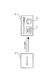
以下では、図1に示すように、MPEG方式で動画像が記録された情報記録媒体であるDVDからDVDプレーヤ10によって動画像を読みとり、このDVDプレーヤ10からアナログ信号により出力されたベースバンドストリームを、デジタルビデオ記録装置20によって記録する場合を想定して説明する。
【0046】
デジタルビデオ記録装置20は、ベースバンドストリームに対してMPEG方式に基づいた符号化処理を行うMPEGエンコーダ21と、このMPEGエンコーダ21によって生成されたMPEGストリームを記録する記録装置22とを備えている。
【0047】
なお、ベースバンドストリームを出力する機器としては、以下の説明においてDVDプレーヤ10を例に挙げるが、特にDVDプレーヤ10に限定されるものではなく、例えば衛星放送を受信して映像信号を出力する衛星放送受信装置や、例えば各種のテープ状記録媒体やディスク状記録媒体などに記録された動画像を読み取って映像信号として出力するような各種の映像機器であってもよい。
【0048】
また、ベースバンドストリームを変換することによりMPEG方式で記録する機器としては、以下の説明においてデジタルビデオ記録装置20を例に挙げるが、このデジタルビデオ記録装置20としては、例えばハードディスク装置内に動画像をデジタルデータとして記録する各種のコンピュータ装置や、各種のテープ状記録媒体やディスク状記録媒体などに動画像を記録する記録装置などを用いることができる。すなわち、記録装置22としては、ハードディスク装置であってもよいし、DVD−RWやDVD−RAM等のような書き込み可能なDVDやなどであってもよい。
【0049】
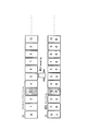
ここで、DVDプレーヤ10からは、図2(a)に示すように、動画像を構成する一連のフレーム(1画面分の画像)がベースバンドストリームとして出力される。このとき、図2(a)中において網がけして示す第3のフレームが、改変されているものとする。
【0050】
そして、デジタルビデオ記録装置20に搭載されたMPEGエンコーダ21においては、ベースバンドストリームに含まれる各フレームを順次MPEG方式に基づいてエンコード処理してゆくこととなるが、以下では、図2(b)に示すように、改変された第3のフレームがPピクチャとしてエンコード処理される場合を想定する。
【0051】
このとき、Pピクチャである第3のフレームは、MPEG圧縮による動き補償の効果によって、Iピクチャである第0のフレームと比較しておよそ1/3程度のデータ量で十分な画質を得られることが期待される。しかしながら、MPEGエンコーダ21は、第3のフレームがDVDプレーヤ10からベースバンドストリームとして出力される時点で改変されていることから、この第3のフレームをMPEG圧縮する際に動き補償に用いることができるようなリファレンスをみつけることができない。
【0052】
このため、第3のフレームは、Pピクチャでありながら、Iマクロブロックの比率が高くなってしまう。換言すると、第3のフレームの画質を十分に確保するためには、Iピクチャである第0のフレームと同程度のデータ量が必要とされることとなる。
【0053】
しかしながら、第3のフレームは、Pピクチャであることから第0のフレームと比較して1/3程度のデータ量に抑制され、このときに全てのマクロブロックが強く量子化されることにより、画質が大きく劣化することとなる。
【0054】
一方、MPEGエンコーダ20は、第6のフレームをPピクチャとしてMPEGエンコードする際に、第3のフレームからの動き補償を期待することができない。このため、この第6のフレームの画質も大きく劣化することとなる。また、次のPピクチャである第9のフレームは、第6のフレームからの動き補償が可能であるが、第6のフレームの画質が大きく劣化していることから、画質が劣化することとなる。また、これらPピクチャの中間にあるBピクチャ、すなわち第4のフレーム、第5のフレーム、第7のフレーム、及び第8のフレームも、同様にして画質の劣化が生じる。このような画質の劣化は、改変が施された第3のフレームを含むGOPにおける最後のフレームまで継承される。
【0055】
上述のように、ベースバンドストリーム内の1つのフレームに対して改変を施すことにより、このベースバンドストリームを変換して生成されたMPEGストリームにおいては10フレーム以上程度の多くのフレームの画質が劣化してしまうこととなる。したがって、アナログ信号を介して動画像を不正に複製することを確実に防止することができる。
【0056】
なお、図2及び上述の説明においては、改変が施された第3のフレームが、MPEGストリームにおいてPピクチャとしてエンコードされた場合を想定しているが、上述した画質劣化の効果は、改変を施したフレームがBピクチャとしてエンコードされる場合には期待することができない。したがって、DVDプレーヤ10側で、ベースバンドストリームを構成する各フレームの中からフレームに対して改変を施す周期をランダムに変化させたり、ランダムに選出した複数のフレームに対して改変を施すなどすることが望ましい。これにより、改変を施したフレームがPピクチャとしてエンコードされる確率を十分に高めることができ、複製された動画像に対して確実に劣化を生ぜしめることができる。
【0057】
つぎに以下では、動画像がDVD30にMPEG方式で記録された状態で、予め上述したような改変が施されている場合について説明する。なお、以下ではDVD30を例示して説明するが、MPEG方式で記録されていれば、他の各種情報記録媒体であってもよい。
【0058】
この場合に、図3に示すように、DVD30に記録された動画像をDVDプレーヤ10によって読み取り、MPEGストリームのままでデジタル信号としてデジタルビデオ記録装置20に出力し、このデジタルビデオ記録装置20内の記録装置22に複製して記録することを想定する。また、DVD30にMPEG方式で記録された動画像は、図4(a)に示すように、Bピクチャである第3のフレームが改変されているものとする。
【0059】
この場合には、DVDプレーヤ10からデジタルビデオ記録装置20に対して動画像がMPEGストリームのまま直接伝送されるため、MPEGデコード或いはMPEGエンコードは行われない。したがって、デジタルビデオ記録装置20の記録装置22には、図4(b)に示すように、図4(a)に示した元のMPEGストリームと同様に、Bピクチャである改変された第3のフレームがそのままBピクチャとして記録される。
【0060】
この場合においては、デジタル信号により元のMPEGストリームのままで動画像が伝送されているため、画像の劣化は生じない。このときの不正な複製の防止は、従来から用いられているCPRM等の各種複製防止技術を用いて行うことができる。
【0061】
なお、デジタルビデオ記録装置20側で、例えば解像度を変更して記録する場合には、誤差や動きベクトルの補間が行われるが、改変が施されたBピクチャの性質、すなわち不正な複製の防止効果が損なわれることはない。
【0062】
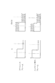
つぎに、図5に示すように、DVD30に記録された動画像をDVDプレーヤ10によって読み取り、アナログ信号であるベースバンドストリームに変換した後にデジタルビデオ記録装置20に出力し、このデジタルビデオ記録装置20内でMPEGエンコード処理を行って記録装置22に記録する場合を想定する。
【0063】
この場合には、改変されたBピクチャである第3のフレームを含む図6(a)に示すようなMPEGストリームが、DVDプレーヤ10内に搭載されたMPEGデコーダによって変換され、図6(b)に示すようなベースバンドストリームとしてデジタルビデオ記録装置20に出力される。このとき、改変が行われた第3のフレームは、改変された情報を含めてそのままアナログ信号として出力される。
【0064】
そして、デジタルビデオ記録装置20側に搭載されたMPEGエンコーダによって、図6(c)に示すように、改変された第3のフレームがIピクチャ又はPピクチャとしてMPEGエンコードされると、図1及び図2を参照しながら説明したようにして画質の劣化が生じることとなる。
【0065】
つぎに以下では、DVDプレーヤ10内でフレームの改変を行う場合について説明する。すなわち、通常のMPEG方式に基づいてDVD30に記録された動画像をDVDプレーヤ10によって読み取り、このDVDプレーヤ10側でフレームの改変を行ってデジタルビデオ記録装置20に出力する場合である。
【0066】
このとき、図7に示すように、DVDプレーヤ10からデジタルビデオ記録装置20に対してデジタル信号により伝送する場合を考える。
【0067】
この場合には、DVDプレーヤ10内に搭載されたMPEGパーサー11が、改変するに際して適当なBピクチャを探し出し、フレームの改変処理を行う画像処理部12によって、このBピクチャに対して改変を施す。これにより、DVD30に記録された図8(a)に示すようなMPEGストリームが、画像処理部12によって、例えば図8(b)に示すようなMPEGストリームに変換される。そして、この変換済みのMPEGストリームが外部のデジタルビデオ記録装置20に出力される。
【0068】
デジタルビデオ記録装置20は、MPEGストリームがデジタル信号として伝送されるため、記録装置22には、図8(c)に示すように、図8(b)に示したMPEGストリームと同様に、Bピクチャである改変された第3のフレームがそのままBピクチャとして記録される。
【0069】
この場合においては、デジタル信号により元のMPEGストリームのままで動画像が伝送されているため、画像の劣化は生じない。このときの不正な複製の防止は、従来から用いられているCPRM等の各種複製防止技術を用いて行うことができる。なお、デジタルビデオ記録装置20側で、例えば解像度を変更して記録する場合には、誤差や動きベクトルの補間が行われるが、改変が施されたBピクチャの性質、すなわち不正な複製の防止効果が損なわれることはない。
【0070】
したがって、例えば課金を支払うなどして正規な手続きを行った場合には、デジタル信号による複製防止策を解除して、デジタルビデオ記録装置20内の記録装置22に複製することが可能であるとともに、この記録装置22に記録されたMPEGストリームを再度アナログ信号を介して不正に複製するに際しては、図1及び図2を参照して説明したようにして画質の劣化が生じることとなる。
【0071】
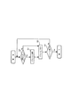
つぎに、0に示すように、DVDプレーヤ10からデジタルビデオ記録装置20に対してアナログ信号により伝送する場合を考える。
【0072】
この場合には、DVD30にMPEG方式で記録された動画像を、DVDプレーヤ10内に搭載されたMPEGデコーダ13によってベースバンドストリームに変換した後に、画像処理部12によって任意のフレームに対して改変を施す。そして、改変が施されたフレームを含むベースバンドストリームは、DVDプレーヤ10に搭載されたNTSCエンコーダ14によってNTSC(National Television System Committee)方式のアナログ信号に変換され、デジタルビデオ記録装置20に出力される。
【0073】
このとき、図10(a)に示すようなDVD30に記録された元のMPEGストリームは、画像処理部12によって図10(b)に示すようなベースバンドストリームとなる。なお、図10(b)においては、第3のフレームが改変された場合を図示している。そして、デジタルビデオ記録装置20側で、図10(c)に示すように、改変された第3のフレームがIピクチャ又はPピクチャとしてMPEGエンコードされると、図1及び図2を参照しながら説明したようにして画質の劣化が生じることとなる。
【0074】
なお、NTSCエンコーダ14に代えて、PAL(Phase Alternation by Line)方式のアナログ信号に変換処理するPALエンコーダや、SECAM(S'Equentiel Couleur'AMemoire)方式のアナログ信号に変換処理するSECAMエンコーダを備えるとしてもよい。
【0075】
なお、図9及び図10においては、MPEGストリームをMPEGデコーダ13によってベースバンドストリームに変換処理した後に、フレームに対する改変を施す場合の例について図示しているが、図7及び図8で図示したように、MPEGストリームに含まれるフレームに対して直接改変を施し、この改変を施した後のMPEGストリームをアナログ信号であるベースバンドストリームに変換して出力した場合についても、上述と同様にしてアナログ信号を介した不正な複製を防止することができることは述べるまでもない。
【0076】
すなわち、フレームに対する改変処理は、MPEGストリームに対して施してもよいし、ベースバンドストリームに対して施してもよい。
【0077】
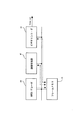
ここで、MPEGストリームに対してフレームの改変を施す場合におけるDVDプレーヤ10での一連の処理について、図11を参照しながら説明する。ここでは、DVDプレーヤ10に、図7に示すように、MPEGパーサー11及び画像処理部12が備えられているものとする。
【0078】
この場合に、DVD30に記録されたMPEGストリームの読み取りが開始されると、DVDプレーヤ10に備えられたMPEGパーサー11は、図12においてステップS10に示すように、ピクチャヘッダの解析を行い、各フレームがIピクチャ、Bピクチャ、又はPピクチャのいずれであるかを解析する。そして、ステップS11において、画像処理部12は、処理対象のピクチャがBピクチャであるか否かを判断する。この判断の結果、Bピクチャである場合には処理を次のステップS12に進め、Bピクチャでない場合には処理をステップS14に進める。
【0079】
ステップS12において、画像処理部12は、処理対象のフレームが改変を施すピクチャであるか否かを判断する。この判断は、ピクチャに対して改変を施す頻度などに応じて行うとすればよい。そして、この判断の結果、改変を施すピクチャである場合には、処理を次のステップS13に進めて、このピクチャに対して改変を施し、改変を施すピクチャでない場合には、処理をステップS14に進める。
【0080】
ステップS14において、画像処理部12は、1ピクチャ分(すなわち、1フレーム分)の画像を出力する。
【0081】
次に、ステップS15において、MPEGパーサー11は、一連のMPEGストリームに対する処理が終了したか否かを判断する。この判断の結果、終了している場合には動作を停止し、終了していない場合には、処理をステップS10に戻して画像処理動作を継続する。
【0082】
以上のようにして、MPEGストリームに対してフレームの改変を施す場合には、ピクチャを単位として改変処理を行う。
【0083】
つぎに、ベースバンドストリームに対してフレームの改変を施す場合におけるDVDプレーヤ10での一連の処理について、図12を参照しながら説明する。ここでは、図13に示すように、MPEGデコード処理を行うMPEGデコーダ40と、MPEGデコーダ40によって伸張された画像(フレーム)が一時的に記憶されるフレームメモリ41と、このフレームメモリ41に記憶されたフレームに対して改変を施す画像処理部42と、フレームメモリ41に記憶された一連のフレームを所定の信号方式に変換して出力するビデオエンコーダ43とがDVDプレーヤ10に備えられているものとする。
【0084】
この場合に、DVD30に記録されたMPEGストリームの読み取りが開始されると、DVDプレーヤ10に備えられたMPEGデコーダ40によって、このMPEGストリームが伸張され、伸張されたフレームが順次フレームメモリ41に出力され、このフレームメモリ41に記憶される。
【0085】
このとき、画像処理部42は、フレームメモリ41内に記憶された各フレームに対して、図12においてステップS20に示すように、このフレームが改変処理の対象となるフレームか否かを判断する。そして、この判断の結果、改変するフレームである場合には処理を次のステップS21に進めて、このフレームに対して改変を施し、改変するフレームでない場合には処理をステップS22に進める。
【0086】
ステップS22において、画像処理部42は、処理対象のフレームをフレームメモリ41に対して出力する。次に、ステップS23において、画像処理部42は、一連のMPEGストリームに相当するフレームに対する処理を全て終了したか否かを判断する。この判断の結果、終了している場合には動作を停止し、終了していない場合には、処理をステップS20に戻して画像処理動作を継続する。
【0087】
一方、ビデオエンコーダ43は、フレームメモリ41に記憶されたフレームを順次読み出して信号変換処理を行い、外部に出力する。
【0088】
以上のようにして、ベースバンドストリームに対してフレームの改変を施す場合には、MPEGデコードを行った後のフレームを単位として改変処理を行う。
【0089】
ところで、上述においては、元のビデオストリーム中に含まれる複数のフレームから選ばれた1つ或いは複数のフレームに対して、個別に改変を行うとして説明している。しかしながら、上述のような構成とすることに限定されるものではなく、元のビデオストリーム中に含まれる複数のフレームの全てに対して改変を加えるとしてもよい。そこで、以下では、全てのフレームに対して改変を加えるとした場合について述べる。
【0090】
この場合においても、上述と同様に、例えばDVD30等の情報記録媒体に対して予め改変が施されたMPEGストリームが記録されているとしてもよいし、DVDプレーヤ10側で改変を加えるとしてもよい。また、MPEGストリームに対してフレームの改変を施すとしてもよいし、ベースバンドストリームに対してフレームの改変を施すとしてもよい。そこで、以下では、全てのフレームに対して改変を加えるとした場合の一例として、図3及び図5に示したように、予め改変が施されたMPEGストリームがDVD30に記録されている場合について説明する。
【0091】
まず、図3に示したように、DVD30に記録された動画像をDVDプレーヤ10によって読み取り、MPEGストリームのままでデジタル信号としてデジタルビデオ記録装置20に出力し、このデジタルビデオ記録装置20内の記録装置22に複製して記録することを想定する。また、DVD30にMPEG方式で記録された動画像は、図14(a)に示すように、全てのピクチャ(フレーム)に対して改変が施されているものとする。
【0092】
この場合には、DVDプレーヤ10からデジタルビデオ記録装置20に対して動画像がMPEGストリームのまま直接伝送されるため、MPEGデコード或いはMPEGエンコードは行われない。したがって、デジタルビデオ記録装置20の記録装置22には、図14(b)に示すように、図14(a)に示した元のMPEGストリームと同様に、各ピクチャが改変された状態のまま記録される。
【0093】
この場合においては、デジタル信号により元のMPEGストリームのままで動画像が伝送されているため、画像の劣化は生じない。このときの不正な複製の防止は、従来から用いられているCPRM等の各種複製防止技術を用いて行うことができる。
【0094】
なお、デジタルビデオ記録装置20側で、例えば解像度を変更して記録する場合には、誤差や動きベクトルの補間が行われるが、改変が施された各ピクチャの性質、すなわち不正な複製の防止効果が損なわれることはない。
【0095】
つぎに、図5に示したように、DVD30に記録された動画像をDVDプレーヤ10によって読み取り、アナログ信号であるベースバンドストリームに変換した後にデジタルビデオ記録装置20に出力し、このデジタルビデオ記録装置20内でMPEGエンコード処理を行って記録装置22に記録する場合を想定する。
【0096】
この場合には、全てのピクチャが改変されているため、図15(a)に示すようなMPEGストリームが、DVDプレーヤ10内に搭載されたMPEGデコーダによって変換され、図15(b)に示すようなベースバンドストリームとしてデジタルビデオ記録装置20に出力される。
【0097】
そして、デジタルビデオ記録装置20側に搭載されたMPEGエンコーダによって、図15(c)に示すように、このベースバンドストリームが再度MPEGエンコードされる。このとき、ベースバンドストリームに含まれる全てのフレームが改変されていることから、確実に画像の劣化が生じることとなる。
【0098】
なお、上述の説明においては、ベースバンドストリームがアナログ信号により伝送された場合について説明したが、ベースバンドストリームがデジタル信号により伝送される場合についても上述と同様にして不正な複製を防止することができる。
【0099】
つぎに以下では、フレームに対して施す「改変」について、具体的な例を上げながら説明することとする。
【0100】
フレームに対して施す改変の第1の例としては、改変前のフレームを構成する少なくとも1つの画素(ピクセル)の情報を、当該画素の近傍に位置する画素の情報と入れ替えることを挙げることができる。これにより、改変を加えたフレームを含むビデオストリームをMPEG方式によりエンコードする際に、改変を加えたフレームが動き補償を阻害し、これによって予測による圧縮を困難にして画質の劣化が生じる。
【0101】
なお、この第1の例における改変を加えるに際して、情報を入れ替える画素の数は、エンコード時に予測による圧縮を十分に困難とする程度以上とすることが必要となる。ただし、情報を入れ替える画素の数を増やしすぎると、このフレーム自体の画質の劣化が目立ち始め、視覚的な影響が生じてしまう。したがって、情報を入れ替える画素の数は、これらの範囲で決定すればよい。
【0102】
また、フレームに対して施す改変の第2の例としては、改変前のフレームのうちの少なくとも一部を変形させることを挙げることができる。これにより、改変を加えたフレームを含むビデオストリームをMPEG方式によりエンコードする際に、改変を加えたフレームが動き補償を阻害し、これによって予測による圧縮を困難にして画質の劣化が生じる。
【0103】
このとき、フレーム内の所定の領域だけを変形させるとしてもよいし、フレームを全体的に変形させるとしてもよい。また、変形を加える位置は、1カ所だけに限定されるものではなく、フレーム内の複数の領域を変形させるとしてもよい。この第2の例における変形は、ひねり、歪み、或いは傾斜など、各種の変形を微少な量だけフレームに対して加えることにより実現することができる。
【0104】
また、複数の連続したフレームに対して変形を加えるに際しては、例えば図16に示すように、連続的に変形の度合いを変化させるとしてもよい。これにより、視覚的な影響を増大させることなく、大きな変形を加えることができ、エンコード時の動き補償を十分に阻害して、予測による圧縮を確実に困難なものとすることができる。
【0105】
また、フレームに対して施す改変の第3の例としては、改変前のフレームにおける色差信号にノイズを付与することを挙げることができる。以下ではこの場合について説明する。
【0106】
ここで、改変を施すフレームにおける1次元方向(例えば横軸方向)の輝度信号(Y)と色差信号(Cb及びCr)との例を、図17に示す。このとき、改変を施す前の波形が、輝度信号と色差信号とで図17に示すように階段状の波形であるものとする。このようなフレームに対して改変を施すに際しては、図17に示すように、輝度信号(Y)はそのままで、色差信号(Cb及びCr)の波形に高周波数帯域のノイズを付与する。
【0107】
なお、人間の視覚は、色の高域信号に対して鈍感であるため、上述のようにして付与したノイズ分の変化は、感知しにくいか、或いは全く感知できないものとなる。
【0108】
ここで、このようにして色差信号にノイズが付与されたビデオストリームに対して、MPEGエンコードを行う場合を考える。なお、MPEGエンコード時に、エンコード対象とされているフレーム(エンコード中のフレーム)の輝度信号(Y)及び色差信号(Cb,Cr)と、このエンコード中のフレームがエンコードに際して参照する元のフレーム(リファレンスフレーム)の輝度信号(Y)及び色差信号(Cb,Cr)との一例を、図18に示す。
【0109】
図18に示した波形において、エンコード中のフレームとリファレンスフレームとの輝度信号を比較すると、水平方向に僅かにずれているだけであるため、リファレンスフレームの波形を破線で挟んで示す部分が、エンコード中の波形を挟んで示す部分に一致する。したがって、エンコード時には、この2つの部分の位置の差を動きベクトルとして生成すればよいこととなる。
【0110】
ところが、色差信号についてエンコード中のフレームとリファレンスフレームとを比較すると、後から付与したノイズが一致しないため、同様にして破線で挟んで示す部分を比べると大きな差が生じていることが分かる。なお、図18において破線で挟んで示す部分を抜粋して並べたものを、図19に図示する。
【0111】
したがって、色差信号については、この大きな差を誤差信号としてMPEGストリームに記録する必要が生じてしまう。このように、色差信号にノイズを付与することによって、予測によるデータ量の圧縮を効率よく行うことを阻害することができる。これにより、エンコード後のMPEGストリームにおけるデータ量を、著しく増大させることができる。このため、特にMPEGストリームの転送ビットレートに制限がある場合には、エンコード後の画質が著しく劣化することとなる。
【0112】
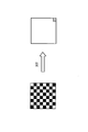
なお、上述の説明においては、輝度信号及び色差信号における1次元方向の波形について説明したが、実際にビデオストリーム中のフレームに対して色差信号にノイズを付与する場合には、図20に示すように、2次元的に分散した成分を有するノイズを付与することが望ましい。これにより、視覚的な影響が生じることなく、エンコード時における画質の劣化に対する効果を向上させることができる。なお、図20においては、フレームに対して付与するノイズのうち、正の振幅を付与する領域を白い領域で示し、負の振幅を付与する領域を黒い領域で示している。
【0113】
また、このような2次元的な成分を有するノイズとしては、MPEGエンコード時に離散コサイン変換(DCT:Discrete cosine transform)を行ったときに、図21に示すように、所定の領域にパワーが集中するものを選択することができる。これにより、上述したように2次元的な成分を有するノイズをMPEGストリームに挿入することを容易とすることができる。
【0114】
具体的には、例えば図22に示すように、MPEGエンコードを行う際に、各フレーム毎の差分を抽出し、DCTを行った後で、特定の係数を入れ替えることによって、フレームにノイズ成分を極めて簡便且つ効果的に挿入することが可能となる。
【0115】
また、例えば図23に示すように、例えばトランスポートストリームやエレメンタリストリームといった形とされたMPEGストリームに対しても、リアルタイムでノイズ成分を挿入することも容易である。すなわち、このようなMPEGストリームをDCT係数までデコードした後に、特定の係数を入れ替えて、再びMPEGエンコードを行ってMPEGストリームを生成する。このとき、図中において斜線部で示す右下のDCT係数が、MPEGでのスキャン順で最後になるので、最も入れ替えが容易である。また、本方式での効果も大きい。
【0116】
なお、本例において加えるノイズのレベルは、元のフレームを256階調のグレースケールとして考えると、20〜30階調程度に相当するレベルとすることが望ましい。これにより、視覚的な影響が生じることがなく、十分に不正な複製を防止することが可能となる。
【0117】
また、MPEGストリームにおいては、いわゆる4:2:0方式により色のコンポーネントが記録されているため、色に割り当てられている情報量が多い。したがって、上述したようにして色差信号にノイズを付与する方法のみならず、他の各種手法により、視覚的な影響を無視できる程度で、且つ再エンコード時に画質の劣化を招くような改変を加えるとしてもよい。具体的には、例えば、色差信号を予め量子化しておくことや、印刷技術で用いられているように色分解を行うことなどの手法が考えられる。
【0118】
なお、上述においては、「フレーム」に対して改変するとして説明したが、フレームを構成する「フィールド」(偶数フィールドと奇数フィールド)に対して改変を施すとしてもよい。
【0119】
つぎに、「フレーム」に対して施す「改変」のその他の例、および、「フィールド」に対して施す「改変」の具体例について説明する。
【0120】
前述したように、フレームに対して「改変」を施す場合、2次元的に分散した成分を有するノイズを付与することが望ましい。これにより、視覚的な影響が生じることなく、エンコード時における画質の劣化に対する効果を向上させることができる。2次元的な成分を有するノイズとして先に図20を参照して説明したように、正の振幅、および負の振幅を付与する領域を交互に配置する構成例があるが、さらに、サイン波を用いる方法がある。
【0121】
具体的には、輝度信号(Y)フレームと、色差信号(Cb及びCr)フレーム中の色差信号(Cb及びCr)フレームに対して、図24に示す構成に従って、Cbフレーム、Crフレームの2次元平面にサイン波を加算して、フレームの改変を施す。
【0122】
図24において、フレーム入力手段111は、動画像を構成するフレーム中の、CbフレームまたはCrフレーム101を選択して重畳処理手段103としての加算手段に対して出力し、高周波帯域信号生成手段112は、CbフレームまたはCrフレーム101とほぼ同様の平面領域に広がる2次元平面に広がるサイン波信号102を重畳処理手段103としての加算手段に出力する。重畳処理手段103は、CbフレームまたはCrフレーム101と2次元平面に広がるサイン波信号102との重畳処理を実行し、改変された改変フレーム(CbまたはCr)104を出力する。
【0123】
サイン波からなる2次元の高域信号の具体的な例としては、垂直、水平方向の原点からの距離をY,Xで表し、サンプル点間の距離を1に正規化して、信号の強度を0−255の正の値で表した場合、信号:Sとして下式によって示されるサイン波が適用可能である。
S=A×Sin((π×X)×n+π×Y)
……(式a1)
なお、上記式において、Aは振幅を表し、A≒20〜30、nは水平方向の周波数がサンプル周波数の何倍であるかを表す数値であり、n≒0.9〜0.6、とする設定が好ましい。
【0124】
上記式によって示される信号Sをフレーム領域であるXY平面上において発生させてフレーム領域に広がるサイン波信号102を生成し、CbフレームまたはCrフレーム101に対して重畳処理手段103によって重畳し、改変フレーム(CbまたはCr)104を出力する。このように2次元的に分散した成分を有するノイズの付与により、視覚的な影響の発生を抑制することが可能となる。
【0125】
このような2次元的に分散したノイズの付与による効果について、図25乃至図27を参照して説明する。
【0126】
改変処理は、CbフレームまたはCrフレームの一方または双方に対して2次元的に実行され、改変処理を施すフレームにおける輝度信号(Y)と色差信号(Cb及びCr)の各フレームにおけるX軸またはY軸方向の信号波形が図25(a)の形状であったとする。横軸がX軸またはY軸方向の位置、縦軸が信号レベルを示す。輝度信号(Y)には、ノイズを加えず、上記式に従った信号:S、すなわち2次元的に分散したサイン波等の高周波信号を色差信号(Cb及びCr)の各フレームに付加することにより、図25(b)に示すように、色差信号(Cb及びCr)の各フレームは、サイン波形状の信号が重畳した信号に変化する。
【0127】
なお、人間の視覚は、色の高域信号に対して鈍感であるため、上述のようにして(Cb及びCr)の各フレームに付与したノイズ分の変化は、感知しにくいか、或いは全く感知できないものとなる。
【0128】
ここで、このようにして色差信号にノイズが付与されたビデオストリームに対して、MPEGエンコードを行う場合を考える。なお、MPEGエンコード時に、エンコード対象とされているフレーム(エンコード中のフレーム)の輝度信号(Y)及び色差信号(Cb,Cr)と、このエンコード中のフレームがエンコードに際して参照する元のフレーム(リファレンスフレーム)の輝度信号(Y)及び色差信号(Cb,Cr)との一例を、図26に示す。
【0129】
図26に示した波形において、(a)の輝度信号(Y)に関するエンコード中のフレームとリファレンスフレームとを比較すると、水平方向に僅かにずれているだけであるため、リファレンスフレームの波形を破線で挟んで示す部分が、エンコード中の波形を挟んで示す部分に一致する。したがって、エンコード時には、この2つの部分の位置の差を動きベクトルとして生成すればよいこととなる。
【0130】
ところが、(b)に示す色差信号(Cb,Cr)についてエンコード中のフレームとリファレンスフレームとを比較すると、波形を破線で挟んで示す部分において、後から付与したノイズ(サイン波)が一致しないため、(a)と同様の対応領域(破線で挟まれた領域)について、エンコード中のフレームとリファレンスフレーが一致せず、差が生じている。例えば、(b)に示す色差信号(Cb,Cr)についてリファレンスフレームのポイントPaの信号レベル変化は、右肩下がりを示しているが、エンコード中のフレームの対応位置Pa’は、右肩上がりを示している。また、リファレンスフレームのポイントPbの信号レベル変化は、右肩上がりを示しているが、エンコード中のフレームの対応位置Pb’は、右肩上がり部分にある。
【0131】
このように、色差信号(Cb,Cr)については、エンコード中のフレームとリファレンスフレームが一致しない。したがって、色差信号については、この差を誤差信号としてMPEGストリームに記録する必要が生じてしまう。このように、色差信号にノイズを付与することによって、予測によるデータ量の圧縮を効率よく行うことを阻害することができる。これにより、エンコード後のMPEGストリームにおけるデータ量を、著しく増大させることができる。このため、特にMPEGストリームの転送ビットレートに制限がある場合には、エンコード後の画質が著しく劣化することとなる。
【0132】
なお、上述の例においては、2次元的に分散したサイン波を色差信号(Cb及びCr)の各フレームに付加する例を示したが、サイン波に限らず、高周波帯域信号、すなわち、MPEGエンコード時に離散コサイン変換(DCT:Discrete cosine transform)を行ったときに、先に説明した図21に示すように、所定の領域にパワーが集中する様々な高周波帯域信号をノイズ信号として選択することが可能である。このような高周波信号を適用することにより、人間の目によるノイズ分の変化が感知しにくいか、或いは全く感知できないものとなり、一方、上述したように、ノイズ成分の影響により、予測によるデータ量の圧縮が阻害され、エンコード後のMPEGストリームにおけるデータ量を、著しく増大させることが可能となる。例えば高周波帯域信号としては、正弦波、三角波、矩形波等が適用可能である。
【0133】
また、重畳処理手段103の実行する高周波帯域信号の重畳処理においては、動画像データを構成するフレーム間の画像データの動きに応じて移動する高周波帯域信号を重畳する処理、あるいは動画像データを構成する各フレームにおいて、固定化された高周波帯域信号を重畳する処理のいずれかを選択して実行し、視覚的に目立ち難い態様での高周波帯域信号の重畳を行なうことが好ましい。
【0134】
また、重畳処理手段103は、重畳処理を実行するフレーム中の画素の輝度、または彩度に応じた強度変化を持つ高周波帯域信号の重畳、例えば、輝度の低い部分には高強度、彩度の高い部分には、低強度の信号を重畳する等の強度調整を実行することで、視覚的に目立ち難い態様での高周波帯域信号の重畳が可能となる。
【0135】
次に、フレームを構成する「フィールド」である偶数フィールドと奇数フィールドに対して改変を施す具体例について説明する。
【0136】
NTSC信号など使用されるインタレース走査方式においては、1つのフレームが2つのフィールドから構成される。図27に示すように、第1フィールドから構成されるフレーム画像と、第2フィールドから構成されるフレーム画像が1つずつ組み合わされて1フレーム画像が構成される。
【0137】
輝度信号(Y)と色差信号(Cb及びCr)の各フレームのそれぞれがこのような2つのフィールドによって1フレームが形成される構成において、CbフレームまたはCrフレームの一方、または両方について、第1フィールドと第2フィールドの色を変更する「改変」構成について説明する。
【0138】
輝度信号(Y)と色差信号(Cb及びCr)は、RGB信号に対して、例えば以下の式によって示す値をとるものとする。
Y=0.2999R+0.587G+0.114B
Cr=0.713(R−Y)+128
Cb=0.564(B−Y)+128
……(式a2)
【0139】
このとき、Cb,Cr各コンポーネントについて、あるピクセルの第1フィールドのオリジナル値がaであり、隣接する第2フィールドのオリジナル値がbであったとする。ただし、a,bは画素信号レベルを示し、上記式に示す範囲の値をとり得るものとする。この時、「改変」処理として画素の値を、図28(a)に示すような設定とする。すなわち、以下のように設定する。第1フィールドの改変処理後の色差信号値をa’、第2フィールドの改変処理後の色差信号値をb’とする。
a’=128
b’=b+(a−128)
……(式a3)
【0140】
すなわち、第1フィールドの色差信号値を一律にa’=128にして、隣接する第2フィールドの値を第1フィールドの値の増加分を調整した値:b’=b+(a−128)として設定する。オリジナル値の第1フィールドと第2フィールドの加算値はa+bであり、第1フィールドと第2フィールドの改変後の加算値もa’+b’=128+b+(a−128)=a+bであり、全体としてバランスは調整されることになり、視覚的な影響は小さく抑えられる。
【0141】
あるいは、図28(b)に示すような設定とする。すなわち、以下のように設定する。第1フィールドの改変処理後の色差信号値をa’、第2フィールドの改変処理後の色差信号値をb’とする。
a’=a+α
b’=b−α
……(式a4)
【0142】
すなわち、第1フィールドの色差信号値を一律にα加算し、a’=a+αとし、隣接する第2フィールドの値を第1フィールドの値の増加分を減算した値:b’=b−αとして設定する。オリジナル値の第1フィールドと第2フィールドの加算値はa+bであり、第1フィールドと第2フィールドの改変後の加算値もa’+b’=a+α+b−α=a+bであり、全体としてバランスは調整されることになり、視覚的な影響は小さく抑えられる。
【0143】
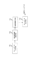
上述の第1フィールドと第2フィールドの色差信号値変更としての「改変」処理を実行する画像処理装置構成について、図29を参照して説明する。フィールドデータ入力手段121は、上述したインターレース画像を構成する第1フィールド、第2フィールドデータをそれぞれ改変値設定手段122に入力する。改変値設定手段122は、予め設定された改変値設定式、例えば上述の(式a3)または(式a4)に従って、各フィールドの改変値を設定し、改変処理実行手段123が、改変値設定手段122の算出した値に基づいて、色差信号(Cb及びCr)の各フィールド値の設定処理を実行し、フィールドデータ出力手段124を介して改変値からなるフィールドデータを出力する。
【0144】
通常の自然画像は近隣ピクセル間の相関が大きいのでフレーム構造でエンコードすると高い圧縮率が得られる。このためエンコーダーは通常フレーム構造でのエンコードを選択する。しかし、上述のフィールド毎の「改変」処理を実行すると、1フレームにおいて、第1フィールドと第2フィールドの色差信号(Cb及びCr)が乖離することとなり、Cb,Cr各コンポーネントについての信号レベルは図30に示すように、信号レベルの差の大きいラインが入れ子になることになる。
【0145】
このため前述の例と同じく、輝度信号(Y)を元に動きベクトルを求ようとしても、輝度信号(Y)に基づく対応ブロックにおいて、色差信号(Cb及びCr)各コンポーネントについての相関が低下し、対応するブロックにおける相関が得難くなり、この差を誤差信号としてMPEGストリームに記録する必要が生じてしまう。このように、色差信号にノイズを付与することによって、予測によるデータ量の圧縮を効率よく行うことを阻害することができる。これにより、エンコード後のMPEGストリームにおけるデータ量を、著しく増大させることができる。このため、特にMPEGストリームの転送ビットレートに制限がある場合には、エンコード後の画質が著しく劣化することとなる。
【0146】
さらに、複数画素からなる画素(ピクセル)領域単位での「改変」処理例について、図31を参照して説明する。図31(a)は、近隣ピクセルの色差情報(Cb及びCr)の少なくともいずれかを1ピクセルに集めるように画像を加工する例である。ここでは色差信号:Cb及びCrの許容値の範囲を16から240とし、無色となる中間値を128とする。
【0147】
図31(a)の例について説明する。隣接4ピクセルそれぞれのオリジナルの色差信号値をa,b,c,dとし、改変後の改変色差信号値をa’,b’,c’,d’とする。改変処理の第1ステップは、隣接4ピクセルの内の3ピクセルの値を128に設定する処理である。すなわち、
a’=128
b’=128
c’=128
とする。
【0148】
さらに、残りの1つのピクセルについて、信号値を下記式によって設定する。
d’=d+(a−128)+(b−128)+(c−128)
……(式a5)
【0149】
すなわち、信号値を128に設定した3ピクセルについて、元の信号値a,b,cと改変設定値:128との差分の和を、信号値:dに加算し、改変信号値:d’として設定する。
【0150】
オリジナル値の4つのピクセルの色差信号加算値はa+b+c+dであり、改変後の信号加算値もa’+b’+c’+d’=128+128+128+d+(a−128)+(b−128)+(c−128)=a+b+c+dであり、全体としてバランスは調整されることになり、視覚的な影響は小さく抑えられる。
【0151】
なお、上述の(式a5)で、ピクセル値:d’の値が16〜240に設定されない場合、すなわち16未満、あるいは240を超える場合は、さらに、以下の調整を実行する。
【0152】
D=d+(a−128)+(b−128)+(c−128)<16の場合、
d’=16に設定、
a’=128−((16−D)/3)
b’=128−((16−D)/3)
c’=128−((16−D)/3)
【0153】
また、D=d+(a−128)+(b−128)+(c−128)>240の場合、
d’=240に設定、
a’=128+((D−240)/3)
b’=128+((D−240)/3)
c’=128+((D−240)/3)
【0154】
上記処理を施した場合も、改変後の信号加算値は、a’+b’+c’+d’=a+b+c+dであり、全体としてバランスは調整されることになり、視覚的な影響は小さく抑えられる。
【0155】
図31(b)は、近隣ピクセルの色差情報を許される範囲で出来るだけ大きく離すように画像を加工する例である。ここでは許される値の範囲を16から240、無色となる中間値を128とする。図31(b)に示す例について説明する。隣接2ピクセルそれぞれのオリジナルの色差信号値をa,bとし、改変後の改変色差信号値をa’,b’とする。まず、隣接2ピクセルの信号値の加算データ:(a+b)が256以下であるかを判定する。
【0156】
(a+b)≦256の場合には、
一方の改変色差信号値をa’=16として設定し、
他方の改変色差信号値をb’=b+(a−16)として設定する。
【0157】
また、(a+b)>256の場合には、
一方の改変色差信号値をa’=a+(b−240)として設定し、
他方の改変色差信号値をb’=240として設定する。
【0158】
上述の画素単位での改変処理においても、隣接2画素の色差信号のオリジナルの値の加算値:a+bに対して、改変後の色差信号の加算値:a’+b’=a+bであることが保証され、全体としてバランスは調整されることになり、視覚的な影響は小さく抑えられる。
【0159】
上述の複数の画素からなる単位画素領域において、色差信号変更としての「改変」処理を実行する画像処理装置構成について、図32を参照して説明する。フレームデータ入力手段131は、動画像を構成するフレーム画像を単位画素領域設定手段132に入力する。単位画素領域設定手段132は、例えば図31(a)のように4画素、あるいは図31(b)のように2画素の隣接画素を、あらかじめ定めた設定に従って、単位画素領域として設定する。改変処理実行手段133は、単位画素領域設定手段132の設定した単位画素領域について、予め設定された改変値設定式、例えば上述の(式a5)または図31(b)に対応する処理に従って、各画素の改変値の設定処理を実行し、フレームデータ出力手段134を介して改変値からなるフレームデータを出力する。
【0160】
上述の画素単位領域毎の改変処理は、要約すると以下の2つの処理ステップを実行するものとしてまとめることができる。すなわち、動画像データを構成し、輝度信号および色差信号成分を含む画素データからなるフレーム画像の色差信号成分フレームに対して、色差信号成分フレームの複数の隣接画素からなる領域を単位画素領域として設定する単位画素領域設定ステップと、単位画素領域に含まれるn個の画素のオリジナル信号値をa1〜anとし、それぞれの改変信号値をa1’〜an’としたとき、改変信号値の加算値:Σak’(ただしk=1〜n)をオリジナル信号値の加算値:Σak(ただしk=1〜n)と等価、すなわち、Σak’=Σakとなる設定の下に各隣接画素の色差信号値の変更処理を実行する改変処理ステップである。
【0161】
このような単位画素単位での色差信号値の変更による改変処理を行なうことで、前述の例と同じく、輝度信号(Y)を元に動きベクトルを求ようとしても、輝度信号(Y)に基づく対応ブロックにおいて、色差信号(Cb及びCr)各コンポーネントについての相関が低下し、対応するブロックにおける相関が得難くなり、この差を誤差信号としてMPEGストリームに記録する必要が生じてしまう。従って、データ圧縮の効率化を阻害することができる。これにより、エンコード後のMPEGストリームにおけるデータ量を増大させることができる。このため、特にMPEGストリームの転送ビットレートに制限がある場合には、エンコード後の画質が著しく劣化することとなる。
【0162】
以上、特定の実施例を参照しながら、本発明について詳解してきた。しかしながら、本発明の要旨を逸脱しない範囲で当業者が該実施例の修正や代用を成し得ることは自明である。すなわち、例示という形態で本発明を開示してきたのであり、限定的に解釈されるべきではない。本発明の要旨を判断するためには、冒頭に記載した特許請求の範囲の欄を参酌すべきである。
【0163】
なお、明細書中において説明した一連の処理はハードウェア、またはソフトウェア、あるいは両者の複合構成によって実行することが可能である。ソフトウェアによる処理を実行する場合は、処理シーケンスを記録したプログラムを、専用のハードウェアに組み込まれたコンピュータ内のメモリにインストールして実行させるか、あるいは、各種処理が実行可能な汎用コンピュータにプログラムをインストールして実行させることが可能である。
【0164】
例えば、プログラムは記録媒体としてのハードディスクやROM(Read Only Memory)に予め記録しておくことができる。あるいは、プログラムはフレキシブルディスク、CD−ROM(Compact Disc Read Only Memory),MO(Magneto optical)ディスク,DVD(Digital Versatile Disc)、磁気ディスク、半導体メモリなどのリムーバブル記録媒体に、一時的あるいは永続的に格納(記録)しておくことができる。このようなリムーバブル記録媒体は、いわゆるパッケージソフトウエアとして提供することができる。
【0165】
なお、プログラムは、上述したようなリムーバブル記録媒体からコンピュータにインストールする他、ダウンロードサイトから、コンピュータに無線転送したり、LAN(Local Area Network)、インターネットといったネットワークを介して、コンピュータに有線で転送し、コンピュータでは、そのようにして転送されてくるプログラムを受信し、内蔵するハードディスク等の記録媒体にインストールすることができる。
【0166】
なお、明細書に記載された各種の処理は、記載に従って時系列に実行されるのみならず、処理を実行する装置の処理能力あるいは必要に応じて並列的にあるいは個別に実行されてもよい。
【0167】
【発明の効果】
本発明においては、ビットストリームに含まれる単位グループのうちの少なくとも1つのフレームが、アナログ信号に変換した後に再び上記動画像圧縮方式に従ってエンコードした際に、動き補償を阻害し、これにより予測による圧縮を困難にして画質の劣化を招くように改変されている。したがって、アナログ方式に変換後に再度エンコードを行うことによる不正な複製を防止することができる。なお、デジタル方式の信号を介しての複製は、従来から利用されているCPRMなどの技術を用いればよい。このため、本発明によれば、不正な複製を確実に防止して、著作権の保護に貢献することができる。また、本発明においては、フレームに加える改変が視覚的な影響が無視できる程度であることから、複製をせずに視聴する場合には違和感が生じない。
【0168】
また、本発明の構成によれば、フレーム単位またはフィールド単位、あるいは画素領域単位による色差信号に改変を加える構成とし、動画像圧縮方式に従ってエンコードした際に、輝度信号に対応するブロックにおける色差信号の相関を低下させる構成としたので、動きベクトルの取得が困難となり、予測符号化が困難になり、データ圧縮の効率化を阻害することができ、エンコード後のMPEGストリームにおけるデータ量を増大させることができる。このため、特にMPEGストリームの転送ビットレートに制限がある場合には、エンコード後の画質が著しく劣化することとなり、不正な複製防止、著作権保護に貢献することができる。
【0169】
したがって、本発明によれば、動画像の不正な複製を確実に防止することを可能とするデジタル信号出力方法、及びデジタル信号出力装置を実現することができる。また、不正な複製を確実に防止することが可能な形で動画像が記録されてなる情報記録媒体を実現することができる。
【図面の簡単な説明】
【図1】本発明を適用して不正な複製を防止する機器として例示するDVDプレーヤと、このDVDプレーヤに接続されるデジタルビデオ記録装置とを示す概略図である。
【図2】同例において、不正な複製が防止される仕組みを説明するための模式図である。
【図3】本発明を適用して不正な複製を防止する状態で動画像が記録されたDVDと、このDVDから動画像を複製する機器の接続例を示す概略図である。
【図4】同例において、MPEGストリームが機器間で直接伝送される場合を説明するための模式図である。
【図5】本発明を適用して不正な複製を防止する状態で動画像が記録されたDVDと、このDVDから動画像を複製する機器の別の接続例を示す概略図である。
【図6】同例において、MPEGストリームがベースバンドストリームに変換されて機器間で伝送される場合を説明するための模式図である。
【図7】本発明を適用して、DVDに記録された動画像に改変を加えた上で、機器間で動画像が伝送される場合の接続例を示す概略図である。
【図8】同例において、MPEGストリームが機器間で直接伝送される場合を説明するための模式図である。
【図9】本発明を適用して、DVDに記録された動画像に改変を加えた上で、機器間で動画像が伝送される場合の別の接続例を示す概略図である。
【図10】同例において、MPEGストリームがベースバンドストリームに変換されて機器間で伝送される場合を説明するための模式図である。
【図11】本発明を適用して、MPEGストリームに対して直接改変を加える場合における手順の一例を示すフローチャートである。
【図12】本発明を適用して、ベースバンドストリームに対して直接改変を加える場合における手順の一例を示すフローチャートである。
【図13】同例を実際に実現するために、機器に備えられる構成を示す概略図である。
【図14】本発明を適用して、ビデオストリームに含まれる全フレームに対して改変が加えられた場合における機器間での伝送を説明するための模式図である。
【図15】本発明を適用して、ビデオストリームに含まれる全フレームに対して改変が加えられた場合における機器間での伝送を説明するための模式図である。
【図16】本発明を適用して、ビデオストリームに含まれる複数のフレームに対して連続的な変形を加える場合の例を示す模式図である。
【図17】本発明を適用して、色差信号にノイズを付与する場合の例について説明する模式図である。
【図18】同例において、再エンコードが行われる際のリファレンスフレームとエンコード中のフレームとの信号波型を示す模式図である。
【図19】同例において、リファレンスフレームとエンコード中のフレームとの波形の差分を抽出した状態を示す模式図である。
【図20】本発明を適用して、改変を加えるフレームに対して2次元的なノイズを加える場合の例について説明する模式図である。
【図21】同例において、改変が加えられたフレームに対してDCT変換を行った状態を示す模式図である。
【図22】同例において、MPEGエンコードを行う際にDCT変換を行った後に係数の入れ替えを行うことによりノイズを付与する場合の例について説明する模式図である。
【図23】同例において、MPEGストリームに対して係数の入れ替えを行うことによりノイズを付与する場合の例について説明する模式図である。
【図24】高周波信号の重畳によるノイズ付加構成を示すブロック図である。
【図25】本発明を適用して、色差信号にノイズを付与する場合の例について説明する模式図である。
【図26】同例において、再エンコードが行われる際のリファレンスフレームとエンコード中のフレームとの信号波型を示す模式図である。
【図27】インタレース走査方式におけるフィールドおよびフレーム構成について説明する図である。
【図28】本発明を適用して、各フィールドの色差信号を改変する場合の例について説明する模式図である。
【図29】本発明を適用して、各フィールドの色差信号の改変を実行する画像処理装置構成について説明する模式図である。
【図30】本発明を適用して、各フィールドの色差信号を改変する場合の例について説明する模式図である。
【図31】本発明を適用して、複数画素からなる画素領域の色差信号を改変する場合の例について説明する模式図である。
【図32】本発明を適用して、複数画素からなる画素領域の色差信号の改変を実行する画像処理装置構成について説明する模式図である。
【符号の説明】
10 DVDプレーヤ
11 MPEGパーサー
12 画像処理部
13 MPEGデコーダ
14 NTSCエンコーダ
20 デジタルビデオ記録装置
21 MPEGエンコーダ
22 記録装置
30 DVD
101 CbフレームまたはCrフレーム
102 サイン波信号
103 重畳処理手段
104 改変フレーム
111 フレーム入力手段
112 高周波帯域信号生成手段
121 フィールドデータ入力手段
122 改変値設定手段
123 改変処理実行手段
124 フィールドデータ出力手段
131 フレームデータ入力手段
132 単位画素領域設定手段
133 改変処理実行手段
134 フレームデータ出力手段[0001]
[Field of the Invention]
The present invention relates to a digital signal output method, a digital signal output device, an image processing device, an image processing method, an information recording medium, and a computer program, and in particular, causes deterioration when moving image information is illegally copied. The present invention relates to a digital signal output method, a digital signal output device, an image processing device, an image processing method, an information recording medium, and a computer program that can contribute to copyright protection.
[0002]
[Prior art]
2. Description of the Related Art Conventionally, an AGC pulse method of Macrovision Corporation is known as a so-called copy guard system that prevents unauthorized duplication of moving images in, for example, a video tape recorder apparatus and a satellite broadcasting system.
[0003]
The AGC pulse method is a technique that prevents an output source from being normally recorded by causing an AGC (Automatic Gain Control) mounted in a video tape recorder apparatus to malfunction. The AGC is a circuit for automatically adjusting the gain of an input signal to maintain an appropriate sensitivity, and is widely installed in consumer video tape recorder devices.
[0004]
In general, video signals that are mutually input and output by consumer video equipment include luminance signals, color signals, scanning synchronization signals, color burst signals, and the like. In the video signal, a luminance signal and a color difference signal for one scan are divided on a time axis by a slight interval called horizontal blanking, and a horizontal synchronization signal and a color burst signal are stored in the horizontal blanking. . As for the video signal, a vertical synchronization signal is stored in vertical blanking provided for each field constituting the moving image. In general consumer video equipment, the horizontal synchronization signal and the vertical synchronization signal are used to adjust the scanning timing of the image, and the color signal is demodulated using the color burst signal.
[0005]
In the AGC pulse method, the luminance signal and the color difference signal are not changed, and an incorrect signal is mixed in the blanking portion described above, thereby causing the AGC mounted on the video tape recorder apparatus to malfunction. It is. That is, in the AGC pulse method, the AGC is erroneously operated in this manner, thereby preventing the image signal from being illegally duplicated.
[0006]
[Problems to be solved by the invention]
As described above, in the AGC pulse method, illegal duplication is prevented by including an incorrect signal in the blanking portion of the video signal. Therefore, for example, there is a problem that illegal duplication can be performed only by replacing the synchronization signal of the blanking portion at the time of video duplication.
[0007]
In recent years, for example, information recording media for recording images and sounds in a digital manner, such as DVD (Digital Versatile Disc), are becoming widespread. In DVD, in order to record image information and audio information, an encoding method defined by ISO / IEC11172 (MPEG-1) or ISO / IEC13818 (MPEG-2) is often used. Conventionally, a dedicated recording / reproducing apparatus (hereinafter referred to as a DVD player) has been used for recording and reproducing images, sounds, and the like on such a DVD. In recent years, a so-called personal computer apparatus has been used. Even when used, recording and reproduction are being freely performed. In addition, copying of images and sounds recorded on a DVD to a hard disk device (HDD) mounted on a personal computer device is also performed.
[0008]
As described above, when recording or duplicating an image or sound using a personal computer device, since the blanking portion of the video signal is not used, illegal duplication is prevented depending on the AGC pulse method used conventionally. There was a problem that I couldn't.
[0009]
For example, when a video signal is duplicated digitally using a DVD player or a personal computer device, illegal duplication can be prevented by a technique such as CPRM (Content Protection for Recordable Media). However, for example, in the case of converting to an analog system signal via RGB output and then converting to a digital system again and recording, there is a problem that unauthorized copying cannot be prevented using the CPRM technology or the like. there were.
[0010]
Accordingly, the present invention has been made in view of the above-described conventional situation, and a digital signal output method, a digital signal output device, an image processing device, and an image that can reliably prevent unauthorized duplication of moving images An object is to provide a processing method. It is another object of the present invention to provide an information recording medium on which a moving image is recorded in a form that can reliably prevent unauthorized duplication.
[0011]
[Means for Solving the Problems]
In the video signal output method according to
[0012]
Further claims of the present invention6The digital signal output apparatus according to the present invention is a digital signal output apparatus that outputs a bit stream in accordance with a moving image compression method in which other frames are decoded based on a predetermined frame for each unit group composed of a plurality of consecutive frames. , Unit group abovePreferentially select frames that are not referenced by other frames during decodingFrame modification means for modifying such that the visual influence is negligible, and the frame modification means performs modification when the bitstream is converted into an analog signal and then encoded again according to the moving image compression method. Modifications are made such that the frame impedes motion compensation, thereby making prediction compression difficult and causing image quality degradation.
[0013]
According to a seventh aspect of the present invention, there is provided a program for executing a video signal output process in a digital signal output device, wherein a video image composed of a plurality of continuous frames is displayed on the control unit of the digital signal output device. When outputting as a signal, the video is modified so that the visual influence is negligible by preferentially selecting a frame that is not referenced by other frames during decoding.AddFrame modification stepAnd then runFrame modification stepWhen executing, the control unit,When the above moving image is encoded according to a moving image compression method in which other frames are decoded based on a predetermined frame for each unit group composed of a plurality of continuous frames, the modified frame is subjected to motion compensation. The process of making alterations that impair the image quality and make it difficult to compress by prediction.This is a program to be executed.
[0014]
A recording medium according to an eighth aspect of the present invention is an information recording medium in which a program for executing a video signal output process in a digital signal output device is recorded.BeforeWhen outputting a moving image composed of a plurality of continuous frames to the control unit of the digital signal output device as a video signal, a frame that is not referred to by other frames at the time of decoding is preferentially selected from the moving images. A frame modification step that performs a modification that is negligibleAnd then runFrame modification stepWhen executing, the control unit,When the above moving image is encoded according to a moving image compression method in which other frames are decoded based on a predetermined frame for each unit group composed of a plurality of continuous frames, the modified frame is subjected to motion compensation. The process of making alterations that impair the image quality and make it difficult to compress by prediction.To make it runCharacterized by recording the programAn information recording medium.
[0023]
In the present invention configured as described above, at least one frame included in a video signal output as a bit stream which is a digital signal or as an analog signal is converted into an analog signal, and then the moving image compression method is used again. Is encoded so that the motion compensation is hindered, thereby making it difficult to compress by prediction and causing deterioration in image quality. Therefore, unauthorized duplication due to re-encoding after conversion to the analog system can be prevented. In addition, a technique such as CPRM that has been conventionally used may be used for copying via a digital signal. Therefore, according to the present invention, it is possible to reliably prevent unauthorized duplication and contribute to copyright protection. In addition, in the present invention, since the visual effect of the modification applied to the frame is negligible, there is no sense of incongruity when viewing without duplication.
[0024]
In addition, it is desirable that a frame to be modified in the present invention is selected for a frame that is not referenced from other frames at the time of decoding. Specifically, for example, it is desirable to modify a B picture in an MPEG stream, as will be described in an embodiment described later. As a result, when the bitstream is directly viewed, or when it is viewed or encoded with a regular copy by digital method, the decoding of other frames is not adversely affected, and the original before modification is not affected. It is possible to output a frame or bit stream that hardly changes with respect to the frame (or bit stream).
[0025]
In the present invention, it is possible to modify only one frame in the unit group included in the bitstream. However, as described in an embodiment described later, an image illegally copied by re-encoding In order to reliably deteriorate the image quality, a plurality of frames in the unit group may be modified. In addition, when the modification is added, the modification may be performed only within a predetermined frame, or the subtle modification may be continuously applied to all the frames constituting the unit group.
[0026]
In the present invention, as modifications to be added to the frame, the following modifications can be specifically employed.
[0027]
That is, for example, the modification may be performed by replacing the information of at least one pixel constituting the frame before modification with the information of the pixel located in the vicinity of the pixel. Further, for example, the modification may be made by deforming at least a part of the frame before the modification. Further, for example, the modification may be performed by adding noise to the color difference signal in the frame before modification. By making such a modification, it is possible to cause a deterioration sufficient to prevent the illegal duplication to such an extent that the visual influence can be ignored.
[0028]
In addition, when adding noise to the color difference signal before modification, for example, noise may be added only to a predetermined area of the frame, or noise may be added only in a one-dimensional direction. It is desirable to add two-dimensionally distributed noise to the entire frame. This makes it easy to efficiently modify each unit group included in a series of bitstreams. Specifically, after performing a discrete cosine transform process on the frame to be modified, a predetermined coefficient is replaced, and further encoding is performed according to the above-described moving image compression method, so that noise distributed two-dimensionally over the entire frame to be modified It is possible to add noise to a series of bitstreams simply and efficiently by simply exchanging coefficients.
[0029]
The computer program of the present invention is, for example, a storage medium or communication medium provided in a computer-readable format to a general-purpose computer system capable of executing various program codes, such as a CD, FD, MO, etc. Or a computer program that can be provided by a communication medium such as a network. By providing such a program in a computer-readable format, processing corresponding to the program is realized on the computer system.
[0030]
Other objects, features, and advantages of the present invention will become apparent from a more detailed description based on embodiments of the present invention described later and the accompanying drawings. In this specification, the system is a logical set configuration of a plurality of devices, and is not limited to one in which the devices of each configuration are in the same casing.
[0031]
DETAILED DESCRIPTION OF THE INVENTION
Hereinafter, embodiments of the present invention will be described in detail with reference to the drawings. In the following description, ISO / IEC11172 (MPEG-1) or ISO / IEC13818 (as a moving image compression method in which other frames are decoded based on a predetermined frame for each unit group composed of a plurality of consecutive frames. An example of using an encoding method (hereinafter referred to as MPEG) defined in MPEG-2) will be described. First, an outline of MPEG technology will be described.
[0032]
The present invention is not limited to application to a digital signal output method, a digital signal output device, an image processing device, an image processing method, and an information recording medium using MPEG technology. The present invention can be widely applied to a method using a moving image compression method in which another frame is decoded based on a predetermined frame for each unit group of frames. The present invention is intended to prevent unauthorized duplication of moving images, but by using the same method as described below, not only moving images but also audio information and various digital data are illegal. It is possible to easily establish a technique for preventing the duplication.
[0033]
MPEG is an irreversible compression method using both spatial compression and temporal compression. In MPEG, frames constituting a series of moving images are not independent, and compression (encoding) or expansion (decoding) is performed for each unit group called GOP (Group of Picture). The GOP is composed of an I frame, a P frame, and a B frame.
[0034]
An I frame (Intra Picture) is a frame used as a reference when compressing or expanding other frames in the GOP, and only spatial compression is performed. The spatial compression in the I frame is performed based on a discrete cosine transform (DCT) in units of 8 × 8 pixels (pixels). Since the I frame is only subjected to intra-frame compression, this frame has a lower compression rate and a larger amount of data than other frames.
[0035]
In addition to intra-frame compression, P-frame (Predictive Picture) incorporates prediction only in the forward direction of the time axis and is subjected to time-type (inter-frame) compression based on differences from I frames. Therefore, the P frame is expanded from the intra-frame information and the information of the previous I frame and / or P frame. For this reason, the P frame has a higher compression rate and a smaller data amount than the I frame.
[0036]
A B frame (Bidirectionally Predictive Picture) is subjected to predictive compression in both directions on the time axis based on the difference from the previous and subsequent frames in addition to the intra-frame compression. Therefore, the B frame has a higher compression rate than the P frame.
[0037]
Next, a mechanism for preventing unauthorized duplication by applying the present invention to the video stream using the above-described MPEG technology will be described.
[0038]
Video equipment that outputs a video stream compressed by MPEG technology as a video signal is generally a digital output system that directly outputs the video stream in a digital format, and an analog output system that converts the video stream to an analog format and outputs the video stream. And. Hereinafter, a video stream output in a digital format is referred to as an MPEG stream, and a video stream output in an analog format is referred to as a baseband stream.
[0039]
There are two cases when copying a video signal output from such a video device.
[0040]
In the first case, the MPEG stream output in the digital format is directly recorded in the digital format on an information recording medium such as a hard disk device or a DVD recording device. In this case, unauthorized duplication can be prevented by a conventionally used duplication prevention technique such as CPRM.
[0041]
In the second case, the baseband stream output in the analog system is recorded after MPEG encoding is performed again on the computer device or DVD recording device side, for example. In this case, illegal duplication cannot be prevented by the conventional duplication prevention technology.
[0042]
Therefore, on the video equipment side that outputs the video stream compressed by the MPEG technology, the visual influence can be ignored for at least one frame of each GOP included in the MPEG stream, and the MPEG again By performing a modification that makes compression by prediction difficult when encoding, image degradation occurs when the baseband stream is MPEG-encoded again. Thereby, unauthorized duplication of a moving image via an analog signal can be prevented.
[0043]
The modification added as described above may be added to the baseband stream or may be added to the MPEG stream.
[0044]
Here, a specific description of the “modification” of the frame will be described later. First, a basic outline of how the image is deteriorated will be described first.
[0045]
In the following, as shown in FIG. 1, a moving image is read by a
[0046]
The digital
[0047]
In the following description, the
[0048]
In the following description, the digital
[0049]
Here, as shown in FIG. 2A, the
[0050]
Then, in the
[0051]
At this time, the third frame, which is a P picture, can obtain sufficient image quality with a data amount of about 1/3 compared to the 0th frame, which is an I picture, due to the effect of motion compensation by MPEG compression. There is expected. However, since the
[0052]
For this reason, although the third frame is a P picture, the ratio of the I macroblock becomes high. In other words, in order to sufficiently secure the image quality of the third frame, a data amount comparable to that of the 0th frame that is an I picture is required.
[0053]
However, since the third frame is a P picture, the data amount is suppressed to about 1/3 of that of the 0th frame. At this time, all macroblocks are strongly quantized, so that the image quality is reduced. Will greatly deteriorate.
[0054]
On the other hand, the
[0055]
As described above, by modifying one frame in the baseband stream, the image quality of many frames of about 10 frames or more deteriorates in the MPEG stream generated by converting the baseband stream. Will end up. Therefore, it is possible to reliably prevent the moving image from being illegally copied via the analog signal.
[0056]
In FIG. 2 and the above description, it is assumed that the modified third frame is encoded as a P picture in the MPEG stream. However, the effect of the image quality deterioration described above is not modified. It cannot be expected when the frame is encoded as a B picture. Therefore, on the
[0057]
Next, a case where the above-described modification is performed in advance in a state where a moving image is recorded on the
[0058]
In this case, as shown in FIG. 3, the moving image recorded on the
[0059]
In this case, since the moving image is directly transmitted as an MPEG stream from the
[0060]
In this case, since the moving image is transmitted as the original MPEG stream by the digital signal, the image does not deteriorate. In this case, unauthorized duplication can be prevented by using various duplication prevention techniques such as CPRM which have been used conventionally.
[0061]
For example, when the digital
[0062]
Next, as shown in FIG. 5, the moving image recorded on the
[0063]
In this case, the MPEG stream as shown in FIG. 6A including the third frame which is the modified B picture is converted by the MPEG decoder installed in the
[0064]
Then, when the modified third frame is MPEG-encoded as an I picture or a P picture as shown in FIG. 6C by the MPEG encoder mounted on the digital
[0065]
Next, a case where a frame is modified in the
[0066]
At this time, as shown in FIG. 7, a case is considered in which a digital signal is transmitted from the
[0067]
In this case, the MPEG parser 11 installed in the
[0068]
Since the digital
[0069]
In this case, since the moving image is transmitted as the original MPEG stream by the digital signal, the image does not deteriorate. In this case, unauthorized duplication can be prevented by using various duplication prevention techniques such as CPRM which have been used conventionally. For example, when the digital
[0070]
Therefore, for example, when a regular procedure is performed by paying a charge, it is possible to release the copy prevention measure by the digital signal and to copy to the
[0071]
Next, as shown by 0, consider a case in which an analog signal is transmitted from the
[0072]
In this case, a moving image recorded in the MPEG format on the
[0073]
At this time, the original MPEG stream recorded on the
[0074]
In place of the
[0075]
9 and 10 illustrate an example in which the frame is modified after the MPEG stream is converted into the baseband stream by the
[0076]
That is, the modification process for the frame may be performed on the MPEG stream or the baseband stream.
[0077]
Here, a series of processing in the
[0078]
In this case, when reading of the MPEG stream recorded on the
[0079]
In step S12, the
[0080]
In step S14, the
[0081]
Next, in step S15, the MPEG parser 11 determines whether or not processing for a series of MPEG streams has been completed. If the result of this determination is that it has been completed, the operation is stopped, and if it has not been completed, the processing is returned to step S10 to continue the image processing operation.
[0082]
As described above, when a frame is modified for an MPEG stream, the modification process is performed in units of pictures.
[0083]
Next, a series of processing in the
[0084]
In this case, when reading of the MPEG stream recorded on the
[0085]
At this time, for each frame stored in the
[0086]
In step S <b> 22, the
[0087]
On the other hand, the
[0088]
As described above, when a frame is modified for the baseband stream, the modification process is performed in units of frames after MPEG decoding.
[0089]
By the way, in the above description, it is described that one or a plurality of frames selected from a plurality of frames included in the original video stream are individually modified. However, the present invention is not limited to the above-described configuration, and all of a plurality of frames included in the original video stream may be modified. Therefore, in the following, a case will be described in which modifications are made to all frames.
[0090]
Also in this case, as described above, for example, an MPEG stream that has been modified in advance on an information recording medium such as a
[0091]
First, as shown in FIG. 3, a moving image recorded on the
[0092]
In this case, since the moving image is directly transmitted as an MPEG stream from the
[0093]
In this case, since the moving image is transmitted as the original MPEG stream by the digital signal, the image does not deteriorate. In this case, unauthorized duplication can be prevented by using various duplication prevention techniques such as CPRM which have been used conventionally.
[0094]
For example, when the digital
[0095]
Next, as shown in FIG. 5, a moving image recorded on the
[0096]
In this case, since all the pictures have been altered, the MPEG stream as shown in FIG. 15A is converted by the MPEG decoder installed in the
[0097]
Then, as shown in FIG. 15C, the baseband stream is MPEG-encoded again by the MPEG encoder mounted on the digital
[0098]
In the above description, the case where the baseband stream is transmitted as an analog signal has been described. However, even when the baseband stream is transmitted as a digital signal, unauthorized duplication can be prevented in the same manner as described above. it can.
[0099]
Next, “modification” applied to the frame will be described with a specific example.
[0100]
As a first example of modification applied to a frame, information on at least one pixel (pixel) constituting the frame before modification can be replaced with information on a pixel located in the vicinity of the pixel. . As a result, when a video stream including a modified frame is encoded by the MPEG method, the modified frame hinders motion compensation, which makes it difficult to compress by prediction and causes deterioration in image quality.
[0101]
In addition, when the modification in the first example is added, the number of pixels whose information is replaced needs to be more than a level that makes compression by prediction sufficiently difficult at the time of encoding. However, if the number of pixels whose information is to be replaced is increased too much, the deterioration of the image quality of the frame itself starts to be noticeable, resulting in a visual influence. Therefore, the number of pixels whose information is to be replaced may be determined within these ranges.
[0102]
Further, as a second example of the modification applied to the frame, it is possible to deform at least a part of the frame before the modification. As a result, when a video stream including a modified frame is encoded by the MPEG method, the modified frame hinders motion compensation, which makes it difficult to compress by prediction and causes deterioration in image quality.
[0103]
At this time, only a predetermined area in the frame may be deformed, or the entire frame may be deformed. Further, the position to be deformed is not limited to one place, and a plurality of regions in the frame may be deformed. The deformation in the second example can be realized by applying various deformations such as twist, distortion, or inclination to the frame by a minute amount.
[0104]
Further, when deformation is applied to a plurality of continuous frames, for example, as shown in FIG. 16, the degree of deformation may be changed continuously. Thereby, a large deformation can be added without increasing the visual influence, and the motion compensation at the time of encoding can be sufficiently hindered to make compression by prediction surely difficult.
[0105]
Further, as a third example of the modification applied to the frame, noise can be given to the color difference signal in the frame before the modification. This case will be described below.
[0106]
Here, an example of a luminance signal (Y) and color difference signals (Cb and Cr) in a one-dimensional direction (for example, the horizontal axis direction) in a frame to be modified is shown in FIG. At this time, it is assumed that the waveform before modification is a stepped waveform as shown in FIG. 17 for the luminance signal and the color difference signal. When modifying such a frame, as shown in FIG. 17, the luminance signal (Y) is left as it is, and noise in a high frequency band is added to the waveform of the color difference signals (Cb and Cr).
[0107]
Since human vision is insensitive to high-frequency signals of color, changes in the amount of noise applied as described above are difficult to detect or cannot be detected at all.
[0108]
Here, consider a case where MPEG encoding is performed on a video stream in which noise is added to a color difference signal in this way. Note that, during MPEG encoding, the luminance signal (Y) and color difference signals (Cb, Cr) of a frame to be encoded (frame being encoded) and the original frame (reference) to which the frame being encoded refers during encoding. An example of a luminance signal (Y) and color difference signals (Cb, Cr) of a frame is shown in FIG.
[0109]
In the waveform shown in FIG. 18, when the luminance signal of the frame being encoded and the reference frame are compared, they are only slightly shifted in the horizontal direction. It corresponds to the portion shown with the waveform inside. Therefore, at the time of encoding, the difference between the positions of the two portions may be generated as a motion vector.
[0110]
However, when comparing the frame being encoded and the reference frame with respect to the color difference signal, it can be seen that since the noise applied later does not match, there is a large difference between the portions indicated by the broken lines in the same manner. In addition, what extracted and arranged the part shown between the broken lines in FIG. 18 is shown in FIG.
[0111]
Therefore, for the color difference signal, this large difference needs to be recorded in the MPEG stream as an error signal. As described above, by adding noise to the color difference signal, it is possible to inhibit efficient data amount compression by prediction. As a result, the amount of data in the encoded MPEG stream can be significantly increased. For this reason, particularly when the transfer bit rate of the MPEG stream is limited, the image quality after encoding is significantly deteriorated.
[0112]
In the above description, the one-dimensional waveform in the luminance signal and the color difference signal has been described. However, when noise is actually added to the color difference signal with respect to the frame in the video stream, as shown in FIG. In addition, it is desirable to add noise having two-dimensionally dispersed components. As a result, it is possible to improve the effect on image quality degradation during encoding without causing visual effects. In FIG. 20, among noises applied to a frame, a region to which a positive amplitude is applied is indicated by a white region, and a region to which a negative amplitude is applied is indicated by a black region.
[0113]
As noise having such a two-dimensional component, when discrete cosine transform (DCT) is performed during MPEG encoding, power is concentrated in a predetermined area as shown in FIG. You can choose one. As a result, as described above, it is possible to easily insert noise having a two-dimensional component into the MPEG stream.
[0114]
Specifically, as shown in FIG. 22, for example, when MPEG encoding is performed, a difference for each frame is extracted, and after DCT is performed, a specific coefficient is replaced, thereby adding a noise component to the frame. It becomes possible to insert simply and effectively.
[0115]
For example, as shown in FIG. 23, it is also easy to insert noise components in real time for an MPEG stream in the form of, for example, a transport stream or an elementary stream. That is, after decoding such an MPEG stream up to DCT coefficients, a specific coefficient is replaced and MPEG encoding is performed again to generate an MPEG stream. At this time, the DCT coefficient at the lower right shown by the hatched portion in the drawing is the last in the scan order in MPEG, so that the replacement is most easy. In addition, the effect of this method is great.
[0116]
Note that the level of noise added in this example is desirably a level corresponding to about 20 to 30 gradations when the original frame is considered as a gray scale of 256 gradations. Thereby, there is no visual influence and it is possible to sufficiently prevent unauthorized duplication.
[0117]
Also, in the MPEG stream, color components are recorded by the so-called 4: 2: 0 system, so that the amount of information assigned to the colors is large. Therefore, not only the method of adding noise to the color difference signal as described above, but also a variety of other methods that can ignore the visual influence and add a modification that causes image quality degradation during re-encoding. Also good. Specifically, for example, methods such as quantizing a color difference signal in advance or performing color separation as used in a printing technique are conceivable.
[0118]
In the above description, “frame” is modified. However, “field” (even field and odd field) constituting the frame may be modified.
[0119]
Next, another example of “modification” applied to “frame” and a specific example of “modification” applied to “field” will be described.
[0120]
As described above, when “modifying” a frame, it is desirable to add noise having two-dimensionally dispersed components. As a result, it is possible to improve the effect on image quality degradation during encoding without causing visual effects. As described above with reference to FIG. 20 as noise having a two-dimensional component, there is a configuration example in which regions that give positive amplitude and negative amplitude are alternately arranged. There is a method to use.
[0121]
Specifically, for the luminance signal (Y) frame and the chrominance signal (Cb and Cr) frame in the chrominance signal (Cb and Cr) frame, according to the configuration shown in FIG. The frame is modified by adding a sine wave to the plane.
[0122]
In FIG. 24, a
[0123]
As a specific example of a two-dimensional high-frequency signal composed of sine waves, the distance from the origin in the vertical and horizontal directions is represented by Y and X, the distance between the sample points is normalized to 1, and the signal intensity is When represented by a positive value of 0-255, a sine wave represented by the following expression is applicable as the signal: S.
S = A × Sin ((π × X) × n + π × Y)
(Formula a1)
In the above formula, A represents amplitude, A≈20 to 30, n is a numerical value representing how many times the horizontal frequency is the sample frequency, and n≈0.9 to 0.6. This setting is preferable.
[0124]
A signal S represented by the above equation is generated on the XY plane, which is a frame region, to generate a
[0125]
The effect of applying such two-dimensionally distributed noise will be described with reference to FIGS.
[0126]
The modification process is performed two-dimensionally on one or both of the Cb frame and the Cr frame, and the X-axis or Y in each frame of the luminance signal (Y) and the color difference signals (Cb and Cr) in the frame on which the modification process is performed. Assume that the signal waveform in the axial direction has the shape of FIG. The horizontal axis indicates the position in the X-axis or Y-axis direction, and the vertical axis indicates the signal level. The luminance signal (Y) is not added with noise, and a signal according to the above equation: S, that is, a high-frequency signal such as a two-dimensionally distributed sine wave is added to each frame of the color difference signals (Cb and Cr). Thus, as shown in FIG. 25B, each frame of the color difference signals (Cb and Cr) changes to a signal in which a sine wave signal is superimposed.
[0127]
Since human vision is insensitive to color high-frequency signals, changes in the amount of noise applied to each frame (Cb and Cr) as described above are difficult to detect or not detected at all. It will be impossible.
[0128]
Here, consider a case where MPEG encoding is performed on a video stream in which noise is added to a color difference signal in this way. Note that, during MPEG encoding, the luminance signal (Y) and color difference signals (Cb, Cr) of a frame to be encoded (frame being encoded) and the original frame (reference) to which the frame being encoded refers during encoding. An example of the luminance signal (Y) and the color difference signals (Cb, Cr) of the frame is shown in FIG.
[0129]
In the waveform shown in FIG. 26, when the frame being encoded and the reference frame related to the luminance signal (Y) in (a) are compared, they are only slightly shifted in the horizontal direction. The portion shown sandwiched is the same as the portion shown sandwiching the waveform being encoded. Therefore, at the time of encoding, the difference between the positions of the two portions may be generated as a motion vector.
[0130]
However, when comparing the frame being encoded and the reference frame with respect to the color difference signals (Cb, Cr) shown in (b), the noise (sine wave) added later does not match in the portion shown by sandwiching the waveform with a broken line. In the corresponding area (area between the broken lines) similar to (a), the frame being encoded and the reference frame do not match, and there is a difference. For example, for the color difference signals (Cb, Cr) shown in (b), the signal level change at the point Pa of the reference frame shows a downward slope, but the corresponding position Pa ′ of the frame being encoded shows an upward slope. Show. Further, the signal level change at the point Pb of the reference frame shows a rising right side, but the corresponding position Pb 'of the frame being encoded is at the rising side.
[0131]
Thus, for the color difference signals (Cb, Cr), the frame being encoded and the reference frame do not match. Therefore, for the color difference signal, it is necessary to record this difference as an error signal in the MPEG stream. As described above, by adding noise to the color difference signal, it is possible to inhibit efficient data amount compression by prediction. As a result, the amount of data in the encoded MPEG stream can be significantly increased. For this reason, particularly when the transfer bit rate of the MPEG stream is limited, the image quality after encoding is significantly deteriorated.
[0132]
In the above example, an example in which a two-dimensionally distributed sine wave is added to each frame of the color difference signals (Cb and Cr) is shown. However, the present invention is not limited to a sine wave, but a high-frequency band signal, that is, MPEG encoding. When performing discrete cosine transform (DCT) sometimes, as shown in FIG. 21 described above, it is possible to select various high frequency band signals whose power is concentrated in a predetermined region as noise signals. It is. By applying such a high-frequency signal, the change in noise by the human eye is difficult to detect or cannot be detected at all. On the other hand, as described above, due to the influence of the noise component, the amount of data by prediction is reduced. Compression is impeded and the amount of data in the encoded MPEG stream can be significantly increased. For example, as a high frequency band signal, a sine wave, a triangular wave, a rectangular wave, or the like can be applied.
[0133]
Further, in the superposition processing of the high frequency band signal executed by the superposition processing means 103, the processing for superposing the high frequency band signal that moves according to the movement of the image data between frames constituting the moving image data, or the moving image data is configured. In each frame, it is preferable to select and execute one of the processes for superimposing the fixed high-frequency band signal, and to superimpose the high-frequency band signal in a visually inconspicuous manner.
[0134]
Also, the superimposing
[0135]
Next, a specific example in which an even field and an odd field that are “fields” constituting a frame are modified will be described.
[0136]
In the interlace scanning method used for the NTSC signal or the like, one frame is composed of two fields. As shown in FIG. 27, a frame image composed of the first field and a frame image composed of the second field are combined one by one to form one frame image.
[0137]
In a configuration in which each frame of the luminance signal (Y) and the color difference signals (Cb and Cr) forms one frame by such two fields, the first field for one or both of the Cb frame and the Cr frame is used. A “modification” configuration for changing the color of the second field will be described.
[0138]
The luminance signal (Y) and the color difference signals (Cb and Cr) are assumed to take values indicated by the following equations, for example, with respect to the RGB signals.
Y = 0.2999R + 0.587G + 0.114B
Cr = 0.713 (R−Y) +128
Cb = 0.564 (B−Y) +128
...... (Formula a2)
[0139]
At this time, for each component of Cb and Cr, it is assumed that the original value of the first field of a pixel is a and the original value of the adjacent second field is b. However, a and b represent pixel signal levels and can take values in the range shown in the above equation. At this time, the pixel value is set as shown in FIG. That is, the setting is made as follows. The color difference signal value after the modification process of the first field is a ', and the color difference signal value after the modification process of the second field is b'.
a '= 128
b '= b + (a-128)
...... (Formula a3)
[0140]
That is, the color difference signal value of the first field is uniformly set to a ′ = 128, and the value of the adjacent second field is adjusted to the increment of the value of the first field: b ′ = b + (a−128) Set. The added value of the first field and the second field of the original value is a + b, and the modified added value of the first field and the second field is also a ′ + b ′ = 128 + b + (a−128) = a + b, The balance will be adjusted and the visual impact will be kept small.
[0141]
Alternatively, the setting is as shown in FIG. That is, the setting is made as follows. The color difference signal value after the modification process of the first field is a ', and the color difference signal value after the modification process of the second field is b'.
a ′ = a + α
b ′ = b−α
...... (Formula a4)
[0142]
That is, α is uniformly added to the color difference signal value of the first field to obtain a ′ = a + α, and the value of the adjacent second field is subtracted from the increment of the value of the first field: b ′ = b−α. Set. The sum of the first and second fields of the original value is a + b, and the sum of the first and second fields after modification is also a '+ b' = a + α + b−α = a + b, and the overall balance is adjusted. As a result, the visual impact is minimized.
[0143]
The configuration of the image processing apparatus that executes the “modification” process as the color difference signal value change for the first field and the second field will be described with reference to FIG. The field
[0144]
Since a normal natural image has a large correlation between neighboring pixels, a high compression rate can be obtained by encoding with a frame structure. For this reason, the encoder normally selects encoding with a frame structure. However, when the “modification” process for each field described above is executed, the color difference signals (Cb and Cr) of the first field and the second field diverge in one frame, and the signal levels for the Cb and Cr components are as follows. As shown in FIG. 30, lines with large signal level differences are nested.
[0145]
Therefore, as in the previous example, even if an attempt is made to obtain a motion vector based on the luminance signal (Y), the correlation for each component of the color difference signals (Cb and Cr) is reduced in the corresponding block based on the luminance signal (Y). Therefore, it becomes difficult to obtain the correlation in the corresponding block, and it becomes necessary to record this difference as an error signal in the MPEG stream. As described above, by adding noise to the color difference signal, it is possible to inhibit efficient data amount compression by prediction. As a result, the amount of data in the encoded MPEG stream can be significantly increased. For this reason, particularly when the transfer bit rate of the MPEG stream is limited, the image quality after encoding is significantly deteriorated.
[0146]
Furthermore, an example of “modification” processing in units of a plurality of pixels (pixels) region will be described with reference to FIG. FIG. 31A shows an example of processing an image so that at least one of color difference information (Cb and Cr) of neighboring pixels is collected in one pixel. Here, the range of allowable values of the color difference signals: Cb and Cr is 16 to 240, and the intermediate value that is colorless is 128.
[0147]
An example of FIG. 31A will be described. The original color difference signal values of the adjacent four pixels are a, b, c, d, and the modified color difference signal values after modification are a ′, b ′, c ′, d ′. The first step of the modification process is a process of setting the value of 3 pixels out of 4 adjacent pixels to 128. That is,
a '= 128
b '= 128
c '= 128
And
[0148]
Further, for the remaining one pixel, the signal value is set by the following equation.
d '= d + (a-128) + (b-128) + (c-128)
...... (Formula a5)
[0149]
That is, for 3 pixels in which the signal value is set to 128, the sum of the differences between the original signal values a, b, and c and the modified set value: 128 is added to the signal value: d to obtain the modified signal value: d ′. Set.
[0150]
The color difference signal addition value of the original four pixels is a + b + c + d, and the signal addition value after modification is also a ′ + b ′ + c ′ + d ′ = 128 + 128 + 128 + d + (a−128) + (b−128) + (c−128). = A + b + c + d, and the balance is adjusted as a whole, and the visual influence is kept small.
[0151]
In addition, in the above (formula a5), when the pixel value: d ′ is not set to 16 to 240, that is, less than 16 or exceeds 240, the following adjustment is further performed.
[0152]
If D = d + (a−128) + (b−128) + (c−128) <16,
d ′ = 16,
a '= 128-((16-D) / 3)
b '= 128-((16-D) / 3)
c '= 128-((16-D) / 3)
[0153]
If D = d + (a−128) + (b−128) + (c−128)> 240,
d ′ = 240,
a '= 128 + ((D-240) / 3)
b '= 128 + ((D-240) / 3)
c '= 128 + ((D-240) / 3)
[0154]
Even when the above processing is performed, the signal addition value after modification is a ′ + b ′ + c ′ + d ′ = a + b + c + d, and the balance is adjusted as a whole, and the visual influence is suppressed to a small level.
[0155]
FIG. 31B shows an example of processing an image so that the color difference information of neighboring pixels is separated as much as possible within the allowable range. Here, the range of allowable values is 16 to 240, and the intermediate value that is colorless is 128. An example shown in FIG. 31B will be described. The original color difference signal values of two adjacent pixels are a and b, and the modified color difference signal values after modification are a 'and b'. First, it is determined whether or not the addition data (a + b) of signal values of adjacent two pixels is 256 or less.
[0156]
If (a + b) ≦ 256,
One modified color difference signal value is set as a '= 16,
The other modified color difference signal value is set as b '= b + (a-16).
[0157]
If (a + b)> 256,
One modified color difference signal value is set as a ′ = a + (b−240),
The other modified color difference signal value is set as b '= 240.
[0158]
Even in the modification process in units of pixels described above, it is guaranteed that the added value of the color difference signal after modification: a ′ + b ′ = a + b with respect to the original value of the color difference signal of the adjacent two pixels: a + b. As a result, the balance is adjusted as a whole, and the visual influence is kept small.
[0159]
A configuration of an image processing apparatus that executes “modification” processing as a color difference signal change in the unit pixel region including a plurality of pixels described above will be described with reference to FIG. The frame
[0160]
In summary, the modification processing for each pixel unit area described above can be summarized as executing the following two processing steps. That is, an area composed of a plurality of adjacent pixels of a color difference signal component frame is set as a unit pixel area with respect to a color difference signal component frame of a frame image made up of moving image data and pixel data including a luminance signal and a color difference signal component. Unit pixel region setting step to be performed, and when the original signal values of n pixels included in the unit pixel region are a1 to an and the respective modified signal values are a1 ′ to an ′, the added value of the modified signal values: Σak ′ (where k = 1 to n) is equivalent to the addition value of the original signal value: Σak (where k = 1 to n), that is, the color difference signal value of each adjacent pixel is set under the setting of Σak ′ = Σak. It is a modification process step for executing a change process.
[0161]
By performing the modification process by changing the color difference signal value for each unit pixel as described above, even if an attempt is made to obtain a motion vector based on the luminance signal (Y), it is based on the luminance signal (Y). In the corresponding block, the correlation for each component of the color difference signal (Cb and Cr) is lowered, making it difficult to obtain the correlation in the corresponding block, and it becomes necessary to record this difference as an error signal in the MPEG stream. Therefore, the efficiency of data compression can be hindered. As a result, the amount of data in the encoded MPEG stream can be increased. For this reason, particularly when the transfer bit rate of the MPEG stream is limited, the image quality after encoding is significantly deteriorated.
[0162]
The present invention has been described in detail above with reference to specific embodiments. However, it is obvious that those skilled in the art can make modifications and substitutions of the embodiments without departing from the gist of the present invention. In other words, the present invention has been disclosed in the form of exemplification, and should not be interpreted in a limited manner. In order to determine the gist of the present invention, the claims section described at the beginning should be considered.
[0163]
The series of processes described in the specification can be executed by hardware, software, or a combined configuration of both. When executing processing by software, the program recording the processing sequence is installed in a memory in a computer incorporated in dedicated hardware and executed, or the program is executed on a general-purpose computer capable of executing various processing. It can be installed and run.
[0164]
For example, the program can be recorded in advance on a hard disk or ROM (Read Only Memory) as a recording medium. Alternatively, the program is temporarily or permanently stored on a removable recording medium such as a flexible disk, a CD-ROM (Compact Disc Read Only Memory), an MO (Magneto optical) disk, a DVD (Digital Versatile Disc), a magnetic disk, or a semiconductor memory. It can be stored (recorded). Such a removable recording medium can be provided as so-called package software.
[0165]
The program is installed on the computer from the removable recording medium as described above, or is wirelessly transferred from the download site to the computer, or is wired to the computer via a network such as a LAN (Local Area Network) or the Internet. The computer can receive the program transferred in this manner and install it on a recording medium such as a built-in hard disk.
[0166]
Note that the various processes described in the specification are not only executed in time series according to the description, but may be executed in parallel or individually according to the processing capability of the apparatus that executes the processes or as necessary.
[0167]
【The invention's effect】
In the present invention, when at least one frame of the unit group included in the bitstream is converted into an analog signal and then encoded again according to the moving image compression method, motion compensation is inhibited, thereby compressing by prediction. It has been modified so as to make image quality difficult. Therefore, unauthorized duplication due to re-encoding after conversion to the analog system can be prevented. In addition, a technique such as CPRM that has been conventionally used may be used for copying via a digital signal. Therefore, according to the present invention, it is possible to reliably prevent unauthorized duplication and contribute to copyright protection. In addition, in the present invention, since the visual effect of the modification applied to the frame is negligible, there is no sense of incongruity when viewing without duplication.
[0168]
In addition, according to the configuration of the present invention, the color difference signal is modified by the frame unit, the field unit, or the pixel region unit, and the color difference signal in the block corresponding to the luminance signal is encoded when encoded according to the moving image compression method. Since the correlation is reduced, it becomes difficult to obtain a motion vector, predictive encoding becomes difficult, the efficiency of data compression can be hindered, and the amount of data in the encoded MPEG stream can be increased. it can. For this reason, particularly when the transfer bit rate of the MPEG stream is limited, the image quality after encoding is remarkably deteriorated, which can contribute to illegal duplication prevention and copyright protection.
[0169]
Therefore, according to the present invention, it is possible to realize a digital signal output method and a digital signal output device that can reliably prevent unauthorized duplication of moving images. In addition, it is possible to realize an information recording medium on which a moving image is recorded in a form that can reliably prevent unauthorized duplication.
[Brief description of the drawings]
FIG. 1 is a schematic diagram showing a DVD player exemplified as a device for preventing unauthorized duplication by applying the present invention, and a digital video recording apparatus connected to the DVD player.
FIG. 2 is a schematic diagram for explaining a mechanism for preventing unauthorized duplication in the example.
FIG. 3 is a schematic diagram showing a connection example of a DVD in which a moving image is recorded in a state where illegal copying is prevented by applying the present invention, and a device that copies the moving image from the DVD.
FIG. 4 is a schematic diagram for explaining a case where an MPEG stream is directly transmitted between devices in the example.
FIG. 5 is a schematic diagram showing another connection example of a DVD on which a moving image is recorded in a state where illegal copying is prevented by applying the present invention, and a device that copies the moving image from the DVD.
FIG. 6 is a schematic diagram for explaining a case where an MPEG stream is converted into a baseband stream and transmitted between devices in the example.
FIG. 7 is a schematic diagram illustrating an example of connection in a case where a moving image is transmitted between devices after the moving image recorded on the DVD is modified by applying the present invention.
FIG. 8 is a schematic diagram for explaining a case where an MPEG stream is directly transmitted between devices in the example.
FIG. 9 is a schematic diagram showing another example of connection in the case where a moving image is transmitted between devices after the moving image recorded on the DVD is modified by applying the present invention.
FIG. 10 is a schematic diagram for explaining a case where an MPEG stream is converted into a baseband stream and transmitted between devices in the example.
FIG. 11 is a flowchart illustrating an example of a procedure in the case where the present invention is applied to directly modify an MPEG stream.
FIG. 12 is a flowchart showing an example of a procedure when applying the present invention and directly modifying a baseband stream.
FIG. 13 is a schematic diagram showing a configuration provided in a device to actually realize the example.
FIG. 14 is a schematic diagram for explaining transmission between devices when the present invention is applied and all frames included in a video stream are modified.
FIG. 15 is a schematic diagram for explaining transmission between devices when the present invention is applied and all frames included in a video stream are modified.
FIG. 16 is a schematic diagram illustrating an example in which the present invention is applied and continuous deformation is applied to a plurality of frames included in a video stream.
FIG. 17 is a schematic diagram illustrating an example of applying noise to a color difference signal by applying the present invention.
FIG. 18 is a schematic diagram showing signal waveform types of a reference frame and a frame being encoded in the same example when re-encoding is performed.
FIG. 19 is a schematic diagram showing a state in which a waveform difference between a reference frame and an encoding frame is extracted in the example.
FIG. 20 is a schematic diagram illustrating an example in which two-dimensional noise is added to a frame to be modified by applying the present invention.
FIG. 21 is a schematic diagram showing a state in which DCT conversion has been performed on a modified frame in the example.
FIG. 22 is a schematic diagram for explaining an example in the case where noise is given by performing coefficient replacement after performing DCT conversion when performing MPEG encoding in the same example.
FIG. 23 is a schematic diagram illustrating an example in the case where noise is added by exchanging coefficients for an MPEG stream in the example.
FIG. 24 is a block diagram showing a configuration for adding noise by superposition of high-frequency signals.
FIG. 25 is a schematic diagram illustrating an example of applying noise to a color difference signal by applying the present invention.
FIG. 26 is a schematic diagram showing signal waveform types of a reference frame and a frame being encoded in the same example when re-encoding is performed.
FIG. 27 is a diagram illustrating a field and frame configuration in the interlace scanning method.
FIG. 28 is a schematic diagram illustrating an example in which the present invention is applied to change the color difference signal of each field.
FIG. 29 is a schematic diagram illustrating a configuration of an image processing apparatus that applies the present invention to execute modification of a color difference signal of each field.
FIG. 30 is a schematic diagram illustrating an example in which the color difference signal of each field is modified by applying the present invention.
FIG. 31 is a schematic diagram illustrating an example in which the present invention is applied and a color difference signal of a pixel region including a plurality of pixels is modified.
FIG. 32 is a schematic diagram illustrating an image processing apparatus configuration that applies the present invention and executes modification of a color difference signal of a pixel region including a plurality of pixels.
[Explanation of symbols]
10 DVD player
11 MPEG parser
12 Image processing unit
13 MPEG decoder
14 NTSC encoder
20 Digital video recording device
21 MPEG encoder
22 Recording device
30 DVD
101 Cb frame or Cr frame
102 Sine wave signal
103 Superimposition processing means
104 Modified frame
111 frame input means
112 High frequency band signal generating means
121 Field data input means
122 Modified value setting means
123 Modification processing execution means
124 Field data output means
131 Frame data input means
132 Unit pixel area setting means
133 Modification processing execution means
134 Frame data output means
Claims (8)
上記動画像から、復号化時に他のフレームから参照されないフレームを優先的に選択して視覚的な影響が無視できる程度の改変を加えるフレーム改変ステップを有し、
上記フレーム改変ステップにおいては、上記動画像を、複数の連続したフレームからなる単位グループ毎に、所定のフレームに基づいて他のフレームの復号化が行われる動画像圧縮方式に従ってエンコードした際に、改変を加えたフレームが動き補償を阻害し、これによって予測による圧縮を困難にして画質の劣化を招くような改変を加えること
を特徴とする映像信号出力方法。When outputting a moving image consisting of a plurality of continuous frames as a video signal,
A frame modification step for preferentially selecting a frame that is not referred to by other frames at the time of decoding from the moving image and performing a modification to such an extent that the visual influence can be ignored;
In the frame modification step, when the moving image is encoded according to a moving image compression method in which another frame is decoded based on a predetermined frame for each unit group including a plurality of consecutive frames, the modification is performed. A video signal output method characterized by adding a modification in which a frame added with hinders motion compensation, thereby making it difficult to compress by prediction and causing deterioration in image quality.
を特徴とする請求項1記載の映像信号出力方法。The video signal including the frame modified by the frame modification step is subjected to a moving image compression method in which another frame is decoded based on a predetermined frame for each unit group composed of a plurality of consecutive frames. The video signal output method according to claim 1, wherein the output is a digital signal as a bit stream.
を特徴とする請求項1記載の映像信号出力方法。The video signal output method according to claim 1, wherein in the frame modification step, modification is applied to all frames.
を特徴とする請求項1記載の映像信号出力方法。The video according to claim 1, wherein in the frame modification step, modification is performed by replacing information on at least one pixel constituting the frame before modification with information on a pixel located in the vicinity of the pixel. Signal output method.
を特徴とする請求項1記載の映像信号出力方法。The video signal output method according to claim 1, wherein in the frame modification step, modification is performed by deforming at least a part of a frame before modification.
上記単位グループを構成するフレーム中、復号化時に他のフレームから参照されないフレームを優先的に選択して視覚的な影響が無視できる程度の改変を加えるフレーム改変手段を備え、
上記フレーム改変手段は、上記ビットストリームをアナログ信号に変換した後に再び上記動画像圧縮方式に従ってエンコードした際に、改変を加えたフレームが動き補償を阻害し、これによって予測による圧縮を困難にして画質の劣化を招くような改変を加えること
を特徴とするデジタル信号出力装置。In a digital signal output device that outputs a bitstream according to a moving image compression method in which decoding of other frames is performed based on a predetermined frame for each unit group composed of a plurality of consecutive frames.
A frame modification unit that preferentially selects a frame that is not referred to by other frames at the time of decoding among the frames constituting the unit group and adds a modification that can ignore the visual influence;
When the frame modification means converts the bit stream into an analog signal and then encodes it again according to the moving image compression method, the modified frame inhibits motion compensation, thereby making it difficult to compress by prediction and thereby reducing the image quality. A digital signal output device characterized by adding a modification that causes deterioration of the digital signal.
前記デジタル信号出力装置の制御部に、複数の連続したフレームからなる動画像を映像信号として出力するに際して、上記動画像から、復号化時に他のフレームから参照されないフレームを優先的に選択して視覚的な影響が無視できる程度の改変を加えるフレーム改変ステップを実行させ、
さらに、上記フレーム改変ステップの実行に際して、前記制御部に、上記動画像を、複数の連続したフレームからなる単位グループ毎に、所定のフレームに基づいて他のフレームの復号化が行われる動画像圧縮方式に従ってエンコードした際に、改変を加えたフレームが動き補償を阻害し、これによって予測による圧縮を困難にして画質の劣化を招くような改変を加えるステップを実行させるためのプログラム。A program for executing video signal output processing in a digital signal output device,
When a moving image composed of a plurality of continuous frames is output as a video signal to the control unit of the digital signal output device, a frame that is not referred to by other frames at the time of decoding is preferentially selected from the moving image and visually displayed. The frame modification step, which adds modifications to the extent that the negative effects are negligible ,
Furthermore, when executing the frame modification step , the control unit causes the control unit to decode the moving image by decoding another frame based on a predetermined frame for each unit group including a plurality of consecutive frames. A program for executing a step of adding a modification that, when encoded according to the method, the frame to which the modification has been added impedes motion compensation, thereby making it difficult to compress by prediction and causing deterioration in image quality.
前記デジタル信号出力装置の制御部に、複数の連続したフレームからなる動画像を映像信号として出力するに際して、上記動画像から、復号化時に他のフレームから参照されないフレームを優先的に選択して視覚的な影響が無視できる程度の改変を実行させるフレーム改変ステップを実行させ、
さらに、上記フレーム改変ステップの実行に際して、前記制御部に、上記動画像を、複数の連続したフレームからなる単位グループ毎に、所定のフレームに基づいて他のフレームの復号化が行われる動画像圧縮方式に従ってエンコードした際に、改変を加えたフレームが動き補償を阻害し、これによって予測による圧縮を困難にして画質の劣化を招くような改変を加えるステップを実行させるためのプログラムを記録したことを特徴とする情報記録媒体。Information recording medium der which records a program for executing a video signal output processing in the digital signal output device is,
The control unit of the previous SL digital signal output device, when outputting a moving image composed of a plurality of continuous frames as a video signal, from the moving image, preferentially selected and the frame not referenced by other frames in decoding Perform a frame modification step that performs a modification with negligible visual impact ,
Furthermore, when executing the frame modification step , the control unit causes the control unit to decode the moving image by decoding another frame based on a predetermined frame for each unit group including a plurality of consecutive frames. When encoding according to the method, the modified frame inhibits motion compensation, thereby making it difficult to compress by prediction, and recording a program to execute the modification step that causes deterioration in image quality A characteristic information recording medium.
Priority Applications (1)
| Application Number | Priority Date | Filing Date | Title |
|---|---|---|---|
| JP2002099545A JP4265143B2 (en) | 2001-09-19 | 2002-04-02 | Video signal output method, digital signal output apparatus, image processing apparatus, image processing method, information recording medium, and computer program |
Applications Claiming Priority (3)
| Application Number | Priority Date | Filing Date | Title |
|---|---|---|---|
| JP2001-284951 | 2001-09-19 | ||
| JP2001284951 | 2001-09-19 | ||
| JP2002099545A JP4265143B2 (en) | 2001-09-19 | 2002-04-02 | Video signal output method, digital signal output apparatus, image processing apparatus, image processing method, information recording medium, and computer program |
Publications (3)
| Publication Number | Publication Date |
|---|---|
| JP2003169294A JP2003169294A (en) | 2003-06-13 |
| JP2003169294A5 JP2003169294A5 (en) | 2005-09-08 |
| JP4265143B2 true JP4265143B2 (en) | 2009-05-20 |
Family
ID=26622496
Family Applications (1)
| Application Number | Title | Priority Date | Filing Date |
|---|---|---|---|
| JP2002099545A Expired - Fee Related JP4265143B2 (en) | 2001-09-19 | 2002-04-02 | Video signal output method, digital signal output apparatus, image processing apparatus, image processing method, information recording medium, and computer program |
Country Status (1)
| Country | Link |
|---|---|
| JP (1) | JP4265143B2 (en) |
-
2002
- 2002-04-02 JP JP2002099545A patent/JP4265143B2/en not_active Expired - Fee Related
Also Published As
| Publication number | Publication date |
|---|---|
| JP2003169294A (en) | 2003-06-13 |
Similar Documents
| Publication | Publication Date | Title |
|---|---|---|
| US7961904B2 (en) | Apparatus for embedding and reproducing watermark into and from contents data | |
| EP0769780B1 (en) | Information recording device and information output device | |
| US6639996B2 (en) | Image processing apparatus, image processing method and computer readable memory medium | |
| JP2007124564A (en) | Image coding apparatus, method, and program | |
| JP3772846B2 (en) | Data encoding device, data encoding method, data output device, and data output method | |
| KR100259441B1 (en) | Signal processing apparatus for digital vtr | |
| US7092616B2 (en) | Method and apparatus for copy protecting video content and producing a reduced quality reproduction of video content for personal use | |
| JP3540447B2 (en) | Video encoding apparatus and decoding apparatus | |
| KR101007838B1 (en) | Information processing device and recording medium | |
| JP2002521881A (en) | Watermark detection in compressed video signals | |
| US7421152B2 (en) | Method for resizing an image using the inverse discrete cosine transform | |
| JP2003302960A (en) | Device and method for image display and computer program | |
| EP1377066A2 (en) | Electronic watermark embedding method and apparatus, record medium having electronic watermark | |
| JP4265143B2 (en) | Video signal output method, digital signal output apparatus, image processing apparatus, image processing method, information recording medium, and computer program | |
| EP1255249B1 (en) | Decoder, decoding method, re-encoder, re-encoding method, decoding program and re-encoding program embodied on computer-readable medium | |
| KR19980070575A (en) | Video signal transmission method, superposition information extraction method, video signal output device, video signal receiver and video signal recording medium | |
| JPH1013828A (en) | Picture encoding method, picture signal recording medium and picture decoder | |
| JP3946177B2 (en) | Video encoding apparatus and decoding apparatus | |
| JP4341458B2 (en) | Signal processing device | |
| JP3825367B2 (en) | Compressed video recording / reproducing apparatus and compressed video recording / reproducing method | |
| JP2007510319A (en) | System and method for copy suppression due to repetitive quantization loss | |
| JP2001223989A (en) | Image reproducing device | |
| JP2004080153A (en) | Information superimposing apparatus, information superimposing method, information detection apparatus, information detection method, and superimposed information detection system | |
| JP3852451B2 (en) | Information signal recording apparatus and information signal reproducing apparatus | |
| JP3906822B2 (en) | Encoding apparatus and encoding method |
Legal Events
| Date | Code | Title | Description |
|---|---|---|---|
| A521 | Written amendment |
Free format text: JAPANESE INTERMEDIATE CODE: A523 Effective date: 20050316 |
|
| A621 | Written request for application examination |
Free format text: JAPANESE INTERMEDIATE CODE: A621 Effective date: 20050316 |
|
| A977 | Report on retrieval |
Free format text: JAPANESE INTERMEDIATE CODE: A971007 Effective date: 20071114 |
|
| A131 | Notification of reasons for refusal |
Free format text: JAPANESE INTERMEDIATE CODE: A131 Effective date: 20071204 |
|
| A521 | Written amendment |
Free format text: JAPANESE INTERMEDIATE CODE: A523 Effective date: 20080125 |
|
| A131 | Notification of reasons for refusal |
Free format text: JAPANESE INTERMEDIATE CODE: A131 Effective date: 20080812 |
|
| A521 | Written amendment |
Free format text: JAPANESE INTERMEDIATE CODE: A523 Effective date: 20081007 |
|
| A131 | Notification of reasons for refusal |
Free format text: JAPANESE INTERMEDIATE CODE: A131 Effective date: 20081028 |
|
| A521 | Written amendment |
Free format text: JAPANESE INTERMEDIATE CODE: A523 Effective date: 20081226 |
|
| TRDD | Decision of grant or rejection written | ||
| A01 | Written decision to grant a patent or to grant a registration (utility model) |
Free format text: JAPANESE INTERMEDIATE CODE: A01 Effective date: 20090127 |
|
| A01 | Written decision to grant a patent or to grant a registration (utility model) |
Free format text: JAPANESE INTERMEDIATE CODE: A01 |
|
| A61 | First payment of annual fees (during grant procedure) |
Free format text: JAPANESE INTERMEDIATE CODE: A61 Effective date: 20090209 |
|
| FPAY | Renewal fee payment (event date is renewal date of database) |
Free format text: PAYMENT UNTIL: 20120227 Year of fee payment: 3 |
|
| LAPS | Cancellation because of no payment of annual fees |