JP4264777B2 - Data reproduction method and data reproduction apparatus - Google Patents
Data reproduction method and data reproduction apparatus Download PDFInfo
- Publication number
- JP4264777B2 JP4264777B2 JP15223399A JP15223399A JP4264777B2 JP 4264777 B2 JP4264777 B2 JP 4264777B2 JP 15223399 A JP15223399 A JP 15223399A JP 15223399 A JP15223399 A JP 15223399A JP 4264777 B2 JP4264777 B2 JP 4264777B2
- Authority
- JP
- Japan
- Prior art keywords
- data
- memory
- pointer
- buffer memory
- stage
- Prior art date
- Legal status (The legal status is an assumption and is not a legal conclusion. Google has not performed a legal analysis and makes no representation as to the accuracy of the status listed.)
- Expired - Fee Related
Links
Images


Description
【0001】
本発明はデータ再生方法及びデータ再生装置に関し、特に記録メディアから途切れることなく再生データフレームを出力できるようにしたものである。
【0002】
【従来の技術】
一般的にハード磁気ディスクドライブ(HDD)に代表される、ランダムアクセス可能なノンリニア・メモリ媒体を適用したデータ記録再生装置においては、記録された動画/音声データを再生する際、読み出したデータをバッファメモリヘ転送し、さらに上層のメモリへ転送の後、外部ポートから出力するよう構成されている。
このようなデータ記録再生装置においては、データがフレーム単位で記録メディアに記録され、複数個のデータフレームにはそれぞれ識別番号IDが付せられ管理されている。
【0003】
そして再生時には、利用者によって指定されるIDの一連の順序、すなわちIDストリームにしたがい、これら複数個の記録データフレームから選択的に抽出された各データフレームが時系列で順に再生され、連続した再生データストリームとして出力される。
【0004】
ここでIDストリームは各利用者により個々に指定されるものであるから、その構成は恣意的であり、したがって各再生毎において夫々異なるのが通常である。一方、各IDフレームの記録メディア上への記録は分散されており、よって与えられたIDストリーム毎に、記録メディア上の異なる位置に分散して記録されている着目IDフレームを順次アクセスして再生する必要がある。
【0005】
ここにおいて、例えばハード磁気ディスクドライブや光学式ディスクドライブなどの、記録メディアが回転動作をなす一方で記録・再生ヘッドが機械的移動をしてアクセス動作を行う構成のディスク・レコーダ装置では、例えば再生時における再生開始指示の発生、すなわち再生開始コントロール信号の受理時から、実際に再生データストリームを出力するまでに再生遅延が生じる。この再生遅延の値は機構構成によって異なるが、ビデオ信号における1フレームを単位として、少ないもので5〜6フレームから、大きいものでは数十フレーム程度の再生遅延となるものもある。
【0006】
この遅延要因は、外部信号による再生要求を受けてから再生信号の送出を準備するための再生プロセスの所要時間による。具体的にはハードディスクなど記録メディアから再生データを読み出す際の、記録メディアの回転位置待ちやヘッドのシーク動作等による遅延に加え、記録メディアからの読出し後のメモリ素子などによるバッファリング、さらにビデオ出力部に転送する等の処理に要するオーバーヘッドが遅延を発生させる。
【0007】
このため、VTRと同等の動作を行う現行のディスク・レコーダ装置では、操作時間の精度を保証するプロトコル下で入力される外部信号に対する再生遅延は常に固定の値を保証されている。この固定の再生遅延はエディット・ディレイ(Edit Delay)と称せられ、例えば標準仕様のディスク・レコーダ装置FDDR−7000(商品名)のエディット・ディレイは20フレームとなっている。
【0008】
更に、この再生遅延に対処する従来技術として、予め定めた所定数のデータフレームを前以て先読みして高速アクセス可能のバッファメモリへ蓄積しておき、記録メディアにより発生するアクセス遅延を見掛け上排除するものがある。これは、再生データのエラー処理や符号化復号化処理のためにバッファリング処理が不可欠であることにより具備されるバッファリング機能を利用し、また拡張することにより実現可能な技術であった。
【0009】
【発明が解決しようとする課題】
しかしながら、前記のような先読みバッファリング構成にあっても、例えば時系列で並ぶ一連のデータフレームの各々がそれぞれ分散された位置にある場合や、且つ分散の度合がIDストリーム毎に一定しない等のため、所定量の先読みバッファリングが必ずしも効果的に機能しない場合が生じるという問題があった。この結果、与えられるIDストリームの構成および記録された各データフレーム位置によっては、反応時間にやはり遅延が生じることになり、リアルタイム再生及び可変速再生操作に対する所定の反応時間の保証が困難になる。このため、様々な構成の所与のIDストリームに効果的に対応可能な技術が求められていた。
【0010】
本発明は、前記のような従来技術における問題点を解決するためなされたもので、転送時間に影響されない再生側のメモリ管理が可能な、データ再生方法及びデータ再生装置を提供しようとするものである。
【0011】
【課題を解決するための手段】
かかる課題を解決するため本発明においては、記録メディアに記録したデータフレームを第2段バッファメモリ及び第1段バッファメモリを介して再生データストリームとして順次出力するデータ再生方法及び装置であって、第1段バッファメモリによって第2段バッファメモリから転送されて来る所定数のデータフレームを一時記憶して、所定数のデータフレームのうち順方向端に記憶されたデータフレームでなる順方向駆動領域と逆方向端に記憶されたデータフレームでなる逆方向駆動領域との間に記憶されたデータフレームを処理すべき第1のプロセス対象として設定すると共に、当該第1のプロセス対象に含まれるデータフレームをプレイポインタによって順次指定した順序で再生して再生データストリームとして出力し、第1段バッファメモリによって、プレイポインタが順方向駆動領域又は逆方向駆動領域のデータフレームを再生し始めた時、当該順方向駆動領域又は逆方向駆動領域に記憶されたデータフレームの次のデータフレームの転送を、第2段バッファメモリから、プレイポインタによる再生速度より速い転送速度で、受けると共に、当該次のデータフレームを、第1のプロセス対象の順方向端又は逆方向端のデータフレームとして更新することにより新たに所定数のデータフレームを有する第1のプロセス対象を設定し直して、当該新たな第1のプロセス対象についての再生処理を続け、第2段バッファメモリによって、記録メディアから、プレイポインタを中心として第1のバッファメモリの一時記憶数より大きい所定数のデータフレームを読み出して、プレイポインタによって指定されたデータフレームを中心として第1段バッファへの転送のための第2のプロセス対象として一時記憶し、第2段バッファメモリによって、第1段バッファメモリが新たな第1のプロセス対象を設定し直した時、これに応動して第2のプロセス対象の順方向端又は逆方向端の順方向駆動領域又は逆方向駆動領域のデータフレームを記録メディアから読み出して更新するようにする。
【0012】
前記の記録方法によれば、下段側において再生遅延があってもこれを吸収することにより再生データフレームを途切れさせることなく出力し得る。
【0035】
【発明の実施の形態】
以下、この発明の好適な実施形態を添付図を参照して詳細に説明する。なお、以下に述べる実施形態は、この発明の本質的な構成と作用を示すための好適な例の一部であり、したがって技術構成上好ましい種々の限定が付されている場合があるが、この発明の範囲は、以下の説明において特にこの発明を限定する旨の記載がない限り、これらの形態に限られるものではない。
【0036】
図1は、本発明に係る階層型バッファメモリの一実施形態の構造図であり、メモリ管理の概念をモデル化した図である。
図1に示されるように、本発明に係る階層型バッファメモリA1は、二段構成によるバッファメモリを示し、第1段メモリM1と第2段メモリM2で構成されている。第1段メモリM1は上段側メモリであり、記録容量C1を有する。第2段メモリM2は下段側メモリであり、記録容量C2を有する。ここで記録容量C2は記録容量C1より大であり、またデータアクセス速度は下段側メモリよりも上段側メモリの方が速い。また、第2段メモリM2から下段側には図示されない最下段の記録メディア(例えばディスクストレージ装置)が存在している。
【0037】
二次バッファメモリである第2段メモリM2上には、再生すべきデータフレームのIDが指示された順に時系列で並んだIDストリーム(不図示)の順に、図示されない最下段の記録メディアから転写されたデータフレームの列が記憶容量C2だけ格納されている。さらに上段の一次バッファメモリである第1段メモリM1上には、第2段メモリM2から転写されたデータフレームの列が記憶容量C1だけ格納されている。ここで記憶容量C1は記憶容量C2よりも小であるから、第2段メモリM2に格納されたデータフレームの列の部分集合(サブセット)が第1段メモリM1上に転写格納されていることになる。したがって、下段側のメモリは上段側のメモリを包含している。運用はこの包含関係が常に維持されるように行われる。
【0038】
第1段メモリM1の前方側の端は第1フロントポインタfp1であり、後方側の端は第1リアポインタrp1である。さらに第1フロントポインタfp1から内側の所定の領域は順方向駆動領域Fta1、第1リアポインタrp1から内側の所定の領域は逆方向駆動領域Bta1として設定され、これらの領域へ再生ポインタ(プレイポインタ)PP進入した場合に、新たな転送要求が生じる。
【0039】
ここで順方向の再生開始要求が発生すると、第1段メモリM1上に位置するプレイポインタPPが移動を開始し、この移動にしたがい第1段メモリM1に転写格納されたデータフレームがプレイポインタPPに指されて順次、出力され、再生データストリームStrが生成される。この間、第2段メモリM2から第1段メモリM1へのデータ転写はなされず、また第1段メモリM1の記録内容は更新されない。
【0040】
このようにしてデータフレームがプレイポインタPPに指されて順次、出力され、やがてプレイポインタPPが第1段メモリM1の前方端部に設けた順方向駆動領域Fta1まで移動すると、第1フロントポインタfp1からさらに先のデータフレームを第2段メモリM2から第1段メモリM1へデータ転写する要求が生じ、さらに先のデータフレームが第2段メモリM2から転写されて第1段メモリM1の記録内容が更新される。そして同時に、第1フロントポインタfp1と第1リアポインタrp1も更新される。
【0041】
第2段メモリM2から第1段メモリM1へのデータ転写は、プレイポインタPPの移動速度すなわちデータ再生速度に比して十分高速であるから、プレイポインタPPの移動に支障を生じることなく第1段メモリM1の記録内容の更新がなされる。すなわち、プレイポインタPPが順方向駆動領域Fta1内の最初のデータフレームの再生を行う間に、第1段メモリM1の記録内容の更新がなされ、この順方向駆動領域Fta1も更新されて論理的に前方に移動する。同様に第1フロントポインタfp1と第1リアポインタrp1も更新されて論理的に前方に移動する。この結果、プレイポインタPPが現在再生中の、旧い順方向駆動領域Fta1内に位置していたデータフレームが、新しい順方向駆動領域Fta1には位置しなくなり、論理的に後方へ移動する。そして現在位置のプレイポインタPPが移動して新しい順方向駆動領域Fta1の端に至るまでに時間的余裕が生じる。
【0042】
上記のように、この更新により第1段メモリM1は論理的に再生データストリームStrを前方へ移動することになり、しかも更新はプレイポインタPPが順方向駆動領域Fta1へ至った度に、その都度、直ちに為されるから、移動するプレイポインタPPが第1フロントポインタfp1にまで至ることがなく、常に順方向駆動領域Fta1の分量だけの先読みが確保される。この結果、プレイポインタPPの移動が第1段メモリM1の端にかかることがなく、よって再生データストリームStrが途切れることがない。
【0043】
第1フロントポインタfp1と第1リアポインタrp1は、上記から明らかなように間欠的に更新されるが、一方この更新により、第2段メモリM2上においても第1フロントポインタfp1と第1リアポインタrp1が間欠的に前方へ移動する。
【0044】
上記の操作が繰り返され、第1フロントポインタfp1が第2段メモリM2の前方端部に設けた順方向駆動領域Fta2まで移動すると、ここで第2段メモリM2への最下段メモリ(ディスクストレージ装置)からの新たな転送要求が生じ、さらに先のデータフレームが最下段メモリから転写されて第2段メモリM2の記録内容が更新される。そして同時に、第2フロントポインタfp2と第2リアポインタrp2も更新される。
【0045】
この更新により、第2段メモリM2は論理的に再生データストリームStrを前方へ移動したことになる。しかも第2段メモリM2の更新は、間欠的に移動する第1フロントポインタfp1が順方向駆動領域Fta2へ至った度に、その都度、直ちに為されるから、移動する第1フロントポインタfp1が第2フロントポインタfp2にまで至ることがなく、常に順方向駆動領域Fta2の分量だけの先読みが確保される。この結果、第1フロントポインタfp1の移動が第2段メモリM2の端にかかることがなく、よって第2段メモリM2から第1段メモリM1への転写が途切れることがない。
【0046】
また第2段メモリM2の記録容量C2は第1段メモリM1の記録容量C1よりも大であり、よって順方向駆動領域Fta2も順方向駆動領域Fta1より大きく確保できる。これは更に多段の構成とした場合においても成立し、また上段側の各メモリのアクセス時間は再下段の記録メディアのアクセス時間よりも高速である。
【0047】
したがって、複数段のバッファメモリを経由してデータフレームを上段へ転写する本発明の構成において下段のメモリの順方向駆動領域を大きく確保でき、さらに更新のインタバルも長くなることで階層的構成によって時間的余裕が生じるから、例えば再生データフレームが最下段のディスクストレージ装置上で分散配置されることでシーク時間等に変動がある場合でも、この不定期の遅れを十分吸収することができる。
【0048】
この結果、様々のIDストリームが指示される場合であっても、最上段のデータフレーム再生に途切れが発生することがなく、よって最下段メモリにおける再生遅延を吸収して、連続した再生データストリームを安定に出力することが可能になる。
【0049】
上記は順方向再生動作につき述べたが、逆方向再生動作について同様に運営が行われる。また、順方向駆動領域Fta1、Fta2、逆方向駆動領域Bta1、Bta2の大きさ(データ数、または時間差)は、プレイポインタPPの移動速度と転送時間の期待値から計算され、用途と利用形態に応じて任意に設定することができる。
【0050】
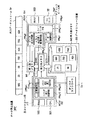
図2は、本発明に係るデータ再生装置の一実施形態のブロック構成図である。
図3は、図2に示すデータ再生装置におけるデータ転写の流れの説明図である。
図4は、図2に示すデータ再生装置の主コントロール部のブロック構成図である。
図5は、図4に示すIDストリーム・テーブルの例の説明図である。
図6は、図4に示すハッシュ・テーブルの例の説明図である。
【0051】
図2に示されるように、本実施形態に係るデータ再生装置DRPは、データストレージ装置DSと、主コントロール部μCと、デジタル信号プロセッサによるサブコントロール部DSPを備え、データストレージ装置DSから読み出したデータが出力データストリームStrとして装置外へ出力される。
【0052】
データストレージ装置DSは、磁気式または光学式ディスク記録メディアから構成される第3段メモリM3と、ディスクコントローラDcntを備えて成る。
【0053】
主コントロール部μCは、CPU101、いずれも半導体メモリであるROM(読出し専用メモリ)102、DRAM(記憶保持動作がなされる随時書込・読出メモリ:以下、RAM)103、バッファメモリとして機能する第2段メモリM2を備えて成り、ROM102には主制御手段PRg11、ポインタ第2制御手段PRg12、メモリ転送第2制御手段Prg13が、いずれもCPU101によって読み取り及び実行可能なプログラムとして格納されている。
【0054】
サブコントロール部DSPは、プロセッサ151、いずれも半導体メモリであるRAM153、ROM154、バッファメモリとして機能する第1段メモリM1を備えて成り、ROM154にはポインタ第1制御手段PRg1、メモリ転送第1制御手段Prg2、データ出力手段PRg3、コントロール手段PRg4が、いずれもプロセッサ151によって読み取り及び実行可能なプログラムとして格納されている。
【0055】
動画/音声データは第3段メモリM3としてのハードディスクに格納されており、このデータはバッファメモリである第2段メモリM2にSCSIバス経由で転送することが出来る。さらに第2段メモリM2と第1段メモリM1との間はDMAバスを介してデータ転送が可能であり、第1段メモリM1上に転送されたデータが、外部I/Oポートから出力される。
【0056】
第3段メモリM3には、複数のデータフレーム(それぞれのIDが23、98、424、436、532、600、753)が記録されている。再生時に、この第3段メモリM3から選択的に読み出されたデータフレームは、メモリ転送第2制御手段Prg13のSCSIバスコントロール機能によって管理されるSCSIバスを経て、第2段メモリM2へ転写され、さらに第2段メモリM2から、メモリ転送第1制御手段Prg2のDMAバスコントロール機能によって管理されるDMAバスを経て、第1段メモリM1へ転写される。
【0057】
このように、第1段メモリM1と第2段メモリM2によって2階層のバッファメモリ構造が実現され、さらに最下段の第3段メモリM3を加えて3階層のメモリ構造が実現されている。ここで、第1段メモリM1、第2段メモリM2、第3段メモリM3のデーク容量は、第3段メモリM3のハードディスク媒体が最も大きく、ついでいずれも半導体メモリである第2段メモリM2、第1段メモリM1の順序となる。一方、アクセス速度に関しては第1段メモリM1が最も高速で、ついで第2段メモリM2、最下段の第3段メモリM3(ハードディスク)の順序となる。
【0058】
上記の3階層のメモリ構造を、図3に基づき更に説明する。
メモリは、上段側から下段側にそれぞれ第1層Ly1、第2層Ly2、第3層Ly3によって構成される。
【0059】
最下段の第3層Ly3に属する第3段メモリM3としてのディスクストレージ装置には、ディスク記録メディア(HDD)上にデータブロックID23、ID98、ID424、ID436、ID532、ID600、ID753が記録されている。
【0060】
ディスク記録メディア上に記録されているデータは、一般的に所定単位で管理されている。例えば、ビデオデータは1フレーム単位(約1MByte)のビデオブロック、オーディオデータは約0.6秒分(32kサンプル)のオーディオブロックとなる。これらブロックは、纏めてデータブロックとして扱うことができるが、ビデオデータの場合、データフレームと記載されることもある。
【0061】
各データブロックには、一意にID(ブロックID)が対応し、各ブロックIDと、ディスク記録メディア(HDD)上の記録位置情報(アドレス)は、図6に示されるハッシュ・テーブルHTABとしてディスク記録メディア上の所定の領域に記録時に格納される。
【0062】
ハッシュ・テーブルHTABには、ブロックIDj、そのブロックのエントリアドレスEAdrj、記録長LNgj(いずれもj=1、2、‥、753、‥)が記録されている。
このハッシュ・テーブルHTABは、リアルタイム性を重視するため再生時にディスク記録メディアから主コントロール部μCのRAM103に転写されRAM上に常駐する。
【0063】
再生されるべきデータストリームStrは、データブロックID600、ID23、ID98、ID753、ID436、ID532、ID424がこの読出順序で読出し再生されるものとする。この再生IDの選定と順序は、利用者により系に指示入力され、主制御手段PRg11によって管理される。主制御手段PRg11は、この指示入力に基づきIDストリーム・テーブルSTABを作成して、RAM103に暫定記憶する。
【0064】
IDストリーム・テーブルSTABには、再生されるデータブロックのIDが再生順に配列されている。再生時には、このIDストリームの示す順に、ハッシュ・テーブルHTABから対応するブロックIDがリファーされ、このブロックに対応するエントリアドレスEAdrjにエントリして、記録長LNgjだけ読出しがなされる。この読出しが完了すると、IDストリーム・テーブルSTABに戻って次の再生順のデータブロックが同様に処理される。
この結果、複数のデータブロックが順次、ディスク記録メディア上の該当アドレスから時系列で連続して再生され、これにより1本の連続する再生ビデオストリームが形成されることになる。これは映画など動画像データの再生に適する。
【0065】
また、IDストリーム・テーブルSTABに、データブロック毎にIDに加えて当該データブロックの再生開始時刻をタイムコードとして設定する場合もある。
【0066】
図4に示されるように、主コントロール部μCのRAM103には前述したIDストリーム・テーブルSTABと、ハッシュ・テーブルHTABが暫定的に記憶される。
【0067】
このIDストリーム・テーブルに基づいて主コントロール部μCが、図3に示されるように、該当するデータブロックの一部分であるデータブロックID98、ID753、ID436を、第3段メモリM3から第2段メモリM2へ転写する。これにより、第2層Ly2に属する第2段メモリM2には、第3段メモリM3からデータブロックID98、ID753、ID436が転写され、記録される。
【0068】
さらに、第2段メモリM2に記録されたデータブロックのうち、図示されるようにID753およびID436の一部分が、サブコントロール部DSPによって第1段メモリM1へ転写され、記録される。最上段である第1段メモリM1は半導体のキャッシュメモリであるから、そのアクセスタイムは高速であり、遅延の発生なく再生データストリームStrを読出し出力することができる。
【0069】
図中の符号IDstは、画像/音声データブロックIDが再生順に配列されたIDストリームであり、この上をプレイポインタPPを移動させることにより対応するデータブロックの画像/音声データを出力再生する。ここでプレイポインタPPは、操作に即時的に反応してIDストリームIDst上を前後に動作するポインタであり、その通過した位置に対応するデータブロックのビデオデータまたはオーディオデータが外部ポートに出力される。図3では、プレイポインタPPがIDストリームIDst上のブロックID753上にあり、したがってブロックID753に対応するデータが出力データストリームStr(図2)として出力されている。
【0070】
このように、IDストリームIDstに登録されたブロックIDに対応する実際の画像/音声データは第3段メモリ(ハードディスク)M3内に格納されているが、出力データストリームStrを途切れなく出力するためには、プレイポインタPPが到達する以前に、該当IDのビデオデータまたはオーディオデータを最上段である第1段メモリM1に用意しておくよう、メモリ管理がなされる必要がある。
【0071】
このメモリ管理動作の原則は「下段のメモリ上のデータは、上段のメモリ上ののデータをストリーム上包含する関係」を保つことである。つまり第1段メモリM1には常にプレイポインタPPを包含するようにデータが用意され、さらに第2段メモリM2には常に第1段メモリM1に用意されるデータを包含するデータを用意するようにする。
このシステムでは、第3段メモリM3であるハードディスクが最終の記憶領域となり、ここに全てのデータが格納されているため、同様に第2段メモリM2で用意したデータが第3段メモリM3上のデータに包含されている関係が成立する。
【0072】
上記のメモリ管理は、いずれもCPU101によって読み取り及び実行可能なプログラムとしてROM102に格納された、主制御手段PRg11、ポインタ第2制御手段PRg12、メモリ転送第2制御手段Prg13と、いずれもプロセッサ151によって読み取り及び実行可能なプログラムとしてROM154に格納された、ポインタ第1制御手段PRg1、メモリ転送第1制御手段Prg2、データ出力手段PRg3、コントロール手段PRg4によって為される。なお、これら各手段の動作は後述される。
【0073】
図7は、本発明に係るデータ再生方法の一実施形態の説明図である。
図8は、図7に示すデータ再生方法の順方向更新動作および逆方向更新動作の処理構造の説明図である。
さらに図9〜図16は、図8に示すデータ再生方法の順方向更新動作の各過程図である。
【0074】
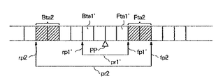
以下、図7に基づきデータ再生方法を説明するが、適宜、前記図1を引用する。
図7中で、データストリームStrのうち、第1フロントポインタfp1と第1リアポインタrp1間の範囲は、前記図1の第1段メモリM1にマッピングされた領域に相当する。プレイポインタPPは、常にこの領域内におかれる。
第1フロントポインタfp1と第1リアポインタrp1のそれぞれの内側方向に、順方向駆動領域Fta1と逆方向駆動領域Bta1が設定されている。
【0075】
また第2フロントポインタfp2と第2リアポインタrp2間の範囲は、前記図1の第2段メモリM2にマッピングされた領域に相当する。前述のように、この領域は上記の第1段メモリM1にマッピングされた領域を包含する。したがって前記第1フロントポインタfp1と第1リアポインタrp1は、常にこの領域内にあるよう管理される。
【0076】
さらに第2フロントポインタfp2と第2リアポインタrp2のそれぞれの内側方向に、順方向駆動領域Fta2と逆方向駆動領域Bta2が設定されている。順方向駆動領域Fta2と逆方向駆動領域Bta2は、夫々前記順方向駆動領域Fta1と逆方向駆動領域Bta1よりも広く設定される。
【0077】
再生の進行につれて、プレイポインタPPは第1フロントポインタfp1の方向へ移動し、順方向駆動領域Fta1に至ると、第1段メモリM1にマッピングされたデータは順方向に更新され、第1フロントポインタfp1と第1リアポインタrp1の位置が順方向に更新される。これにより、順方向駆動領域Fta1と逆方向駆動領域Bta1も更新される。
これら第1段メモリM1のマッピング内容とポインタと駆動領域の更新は、割り当てられたプロセスpr1によって管理される。
【0078】
ここで第1段メモリM1のマッピング内容の更新は、第2段メモリM2を形成するバッファメモリから第1段メモリM1を形成するバッファメモリへの転写であり、転写量はビデオの場合はフレーム単位であり、オーディオの場合はサンプル単位(wоrd)である。
【0079】
一方、更新された第1フロントポインタfp1が第2段メモリM2の順方向駆動領域Fta2に至ると、第2段メモリM2にマッピングされたデータは順方向に更新され、第2フロントポインタfp2と第2リアポインタrp2の位置が順方向に更新される。これにより、順方向駆動領域Fta2と逆方向駆動領域Bta2も更新される。
これら第2段メモリM2のマッピング内容とポインタと駆動領域の更新は、割り当てられたプロセスpr2によって管理される。
【0080】
ここで第2段メモリM2のマッピング内容の更新は、磁気ディスク等の記録メディアから第2段メモリM2を形成するバッファメモリへの転写であり、転写量はシステムがハードディスクを管理するページサイズ(Blоck)に量子化されている。
【0081】
プロセスpr1、pr2はそれぞれが独立して動作するが、両プロセスは共通した単純な原理で動作する。すなわち、これらのプロセスは、内側にある第1フロントポインタfp1と第1リアポインタrp1間の範囲が、外側にある第2フロントポインタfp2と第2リアポインタrp2間の範囲を飛ぴ出さないように包含するよう管理する。
【0082】
プロセスpr1は、両端の第1フロントポインタfp1と第1リアポインタrp1を移動させ、プロセスpr2は、両端の第2フロントポインタfp2と第2リアポインタrp2を移動させる。ここでそれぞれのフロントポインタfpを前方(順方向)に移動させることは、新領域の確保及び転写を意味し、後方(逆方向)へ移動させることは旧領域の解放を意味する。
【0083】
また逆に、リアポインタrpを前方に移動させることは、旧領域の解放を意味し、後方へ移動させることは新領域の確保及び転写を意味する。そして、これらプロセスの共通した動作原理は、「内側のポインタが近付けば自分のポインタを遠ざけ、逆に内側のポインタが遠ざかれば、自分のボインタを近付ける」ことである。
【0084】
上記のようにして順方向更新動作がなされ、その骨子は図8に示されるように、第1プロセスpr1がフロントポインタfp1、リアポインタrp1を前方へずらし、新位置情報を第2プロセスpr2へ通知することにより実行される。
一方、逆方向更新動作も同様に、フロントポインタfp1、リアポインタrp1を後方へずらし、新位置情報を第2プロセスpr2へ通知されることにより実行される。
【0085】
前記において、ポインタの管理はデータ数基準によるものと、時間差基準によるものとの二種類の構成が可能である。
データ数基準は、例えば各段メモリに記録されたデータ中で、読出順序が最後のデータと、現在出力中のデータとの間に存在するデータ数を点検し、このデータ数に基づき管理する。
【0086】
一方、時間差基準は、例えば各段メモリに記録されたデータ中で、読出順序が最後のデータの予定読出時刻と、途中のデータを読出再生中の現在時刻との時間差を演算し、この時間差に基づき管理する。本発明においてはいずれの基準構成も適用可能である。
【0087】
図2に戻り、各手段の動作を説明する。
メモリ転送第1制御手段PRg2は、第2段メモリM2から第1段メモリM1への転送管理と、第1段メモリM1の第1フロントポインタfp1と第1リアポインタrp1間のデータのマッピングを実行する。
【0088】
コントロール手段PRg4は、プレイポインタPPの位置を管理し、プレイポインタPPを常に第1フロントポインタfp1と第1リアポインタrp1間の領域内におくよう制御する。さらに主制御手段PRg11と、制御上必要な情報の授受を行う。
【0089】
ポインタ第1制御手段PRg1は、第1フロントポインタfp1と第1リアポインタrp1のそれぞれの内側方向に、順方向駆動領域Fta1と逆方向駆動領域Bta1を設定し、またこれらを更新する。さらにポインタ第1制御手段PRg1は、データ数基準の構成の場合、最上段メモリに記録されたデータ中で、読出順序が最後のデータと、現在出力中のデータとの間に存在するデータ数を点検して第1データ数とし、プレイポインタPPが第1フロントポインタfp1の方向へ移動し、順方向駆動領域Fta1に至った結果、第1データ数が所定の下限データ数に等しいか又は少なくなると、下段側メモリへ読出順序が更に後のデータの転写要求を行う。
【0090】
また、ポインタ第1制御手段PRg1が、時間差基準の構成の場合、最上段メモリに記録されたデータ中で、読出順序が最後のデータの予定読出時刻と、途中のデータを読出再生中の現在時刻との時間差を第1時間差として演算し、プレイポインタPPが第1フロントポインタfp1の方向へ移動し、順方向駆動領域Fta1に至った結果、第1時間差が所定の下限時間差に等しいか又は短かくなると、下段側メモリへ読出順序が更に後のデータの転写要求を行う。
【0091】
データ出力手段PRg3は、最上段メモリである第1段メモリM1から所定の読出順序に従いデータを出力する。
【0092】
メモリ転送第2制御手段PRg13は、データストレージ装置DSのディスクコントローラDcntへ制御信号を送付することによる第3段メモリM3から第2段メモリM2への転送管理と、第2段メモリM2の第2フロントポインタfp2と第2リアポインタrp2間のデータのマッピングと、第2段メモリM2に記録されたデータ中の少なくとも部分集合の、第1段メモリM1への転写管理を実行する。
【0093】
主制御手段PRg11は、第1フロントポインタfp1と第1リアポインタrp1を常に第2フロントポインタfp2と第2リアポインタrp2間の領域内におくよう制御する。さらにコントロール手段PRg4と、制御上必要な情報の授受を行う。
【0094】
ポインタ第2制御手段PRg12は、第2フロントポインタfp2と第2リアポインタrp2のそれぞれの内側方向に、順方向駆動領域Fta2と逆方向駆動領域Bta2を設定し、またこれらを更新する。さらにポインタ第2制御手段PRg12がデータ数基準の場合、上段側メモリおよび下段側メモリが存在する場合に、上段側のメモリへ転写したデータ中の読出順序が最後のデータと、現在当該メモリに記録されているデータ中で読出順序が最後のデータとの間のデータ数を点検して第2データ数とし、第1フロントポインタfp1が移動して順方向駆動領域Fta2に至って、第2データ数が所与の最低データ数に等しいか又は少なくなると、さらに下段側のメモリへ読出順序が更に後のデータの転写要求を行う。
【0095】
あるいはポインタ第2制御手段PRg12が時間差基準の場合、上段側メモリおよび下段側メモリが存在する場合に上段側のメモリへ転写したデータ中の読出順序が最後のデータの予定読出時刻と、現在当該メモリに記録されているデータ中で読出順序が最後のデータの予定読出時刻との時間差を演算して第2時間差とし、第1フロントポインタfp1が移動して順方向駆動領域Fta2に至って、演算された第2時間差が所与の最低時間差に等しいか又は短かくなると、さらに下段側のメモリへ読出順序が更に後のデータの転写要求を行う。
【0096】
以下、図9〜図16に基づいて、図8に示すデータ再生方法の順方向更新動作の各過程を説明する。図9〜図12は、第1プロセスpr1の動作過程であり、また図13〜図16は、第2プロセスpr2の動作過程である。
【0097】
図9において、第1段メモリM1上の第1プロセスpr1は、その範囲内のポインタとして、プレイポインタPPを保持する。プレイポインタPPは再生の進行につれ移動して、順方向駆動領域Fta1へ至るが、この検出はサブコントロール部DSPによって為され、割り込みで通知される。
【0098】
図10に示されるように、プレイポインタPPが順方向駆動領域Fta1へ至ると、図11中で点線で示されるように、順方向へ移動させた暫定第1プロセスTpr1が設定され、これに伴い第1フロントポインタfp1と第1リアポインタrp1も順方向へ移動して、それぞれ暫定第1フロントポインタTfp1と暫定第1リアポインタTrp1が設定される。
【0099】
暫定第1フロントポインタTfp1と現行の第1フロントポインタfp1との間のデータは、現行の第1段メモリM1上には存在しないから、第2段メモリM2から、この間のデータが転写される。この転写にともない、現行の第1リアポインタrp1と暫定第1リアポインタTrp1の間のデータが解放・廃棄される。ここで第1段メモリM1がリングバッファ構造である場合は、前方部分への転写により後方部分の解放が自動的になされる。
これにより、第1段メモリM1上のデータマッピングが更新される。
【0100】
上記のように更新された結果、図12に示されるように、新第1フロントポインタfp1’と、新第1リアポインタrp1’と、新第1プロセスpr1’に変更され、また駆動領域も更新されて順方向新駆動領域Fta1’、逆方向新駆動領域Bta1’となる。これにより、プレイポインタPPと新第1フロントポインタfp1’との距離が増大し、プレイポインタPPは支障なく移動を続行でき、よって再生データストリームStrが途切れることがない。
【0101】
つぎに図13において、第2段メモリM2上の第2プロセスpr2は、その範囲内のポインタとして第1フロントポインタfp1と第1リアポインタrp1を保持する。第1フロントポインタfp1と第1リアポインタrp1は、前記のように更新されるから、更新の度に移動する。やがて図14に示されるように、新第1フロントポインタfp1’が順方向駆動領域Fta2へ至る。
【0102】
新第1フロントポインタfp1’が順方向駆動領域Fta2へ至ると、図15中で点線で示されるように、順方向へ移動させた暫定第2プロセスTpr2が設定され、これに伴い第2フロントポインタfp2と第2リアポインタrp2も順方向へ移動して、それぞれ暫定第2フロントポインタTfp2と暫定第2リアポインタTrp2が設定される。
【0103】
暫定第2フロントポインタTfp2と現行の第2フロントポインタfp2との間のデータは、現行の第2段メモリM2上には存在しないから、第3段メモリM3から、この間のデータが転写される。この転写にともない、現行の第2リアポインタrp2と暫定第2リアポインタTrp2の間のデータが解放・廃棄される。
これにより、第2段メモリM2上のデータマッピングが更新される。
【0104】
上記のように更新された結果、図16に示されるように、新第2フロントポインタfp2’と、新第2リアポインタrp2’と、新第2プロセスpr2’に変更され、また駆動領域も更新されて順方向新駆動領域Fta2’、逆方向新駆動領域Bta2’となる。これにより、新第1フロントポインタfp1’と新第2フロントポインタfp2’との距離が増大し、第2段メモリM2から第1段メモリM1への転写が支障なく続行可能になる。よって第1段メモリM1からの再生データストリームStrの出力が途切れることがない。
【0105】
図17は第1プロセスpr1の順方向更新動作のフローチャートであり、図18は、第2プロセスpr2の順方向更新動作のフローチャートである。
以下、両図に基づき動作を説明する。
【0106】
第1プロセスpr1の順方向更新動作では、第1段メモリM1から1フレームを再生データストリームStrとして送出する(ステップS1)。ついでプレイポインタPPが1フレーム移動される(ステップS2)。
【0107】
ここでプレイポインタPPが順方向駆動領域Fta1へ達したかを点検し(ステップS3)、達していれば第1フロントポインタfp1を移設して暫定第1フロントポインタTfp1とする(ステップS4)。また第1リアポインタrp1を移設して、暫定第1リアポインタTrp1とする(ステップS5)。
【0108】
つぎに、第1プロセスpr1を暫定第1プロセスTpr1とする(ステップS6)。ついで第2段メモリM2から第1段メモリM1へ、暫定第1フロントポインタTfp1と第1フロントポインタfp1の差分ブロックの転送を受ける(ステップS7)。
【0109】
暫定第1フロントポインタTfp1、暫定第1リアポインタTrp1を夫々、新第1フロントポインタfp1’、新第1リアポインタrp1’に設定し、さらに暫定第1プロセスTpr1を新第1プロセスpr1’に設定する(ステップS8)。
【0110】
順方向駆動領域と逆方向駆動領域を夫々、更新してFta1’、Bta1’とする(ステップS9)。さらに新第1フロントポインタfp1’と、新第1リアポインタrp1’の情報を第2プロセスpr2へ送付する(ステップS10)。
【0111】
第2プロセスpr2の順方向更新動作は、更新された新第1フロントポインタfp1’、新第1リアポインタrp1’を受理したかを点検し(ステップS21)、受理を確認すると、ついで新第1フロントポインタfp1’が順方向駆動領域Fta2へ達したかの点検がなされる(ステップS22)。
【0112】
新第1フロントポインタfp1’が順方向駆動領域Fta2へ達すると、第2フロントポインタfp2を移設して暫定第2フロントポインタTfp2とし、また第2リアポインタrp2を移設して暫定第2リアポインタTrp2とする(ステップS23)。
【0113】
つぎに、第3段メモリM3のディスク記録メディアから第2段メモリM2へ、暫定第2フロントポインタTfp2と第2フロントポインタfp2との差分ブロック分を転送する(ステップS24)。
【0114】
暫定第2フロントポインタTfp2、暫定第2リアポインタTrp2を夫々、新第2フロントポインタfp2’、新第2リアポインタrp2’に設定し、さらに暫定第2プロセスTpr2を新第2プロセスpr2’に設定する(ステップS25)。
そして順方向駆動領域と逆方向駆動領域を夫々、更新してFta2’、Bta2’とする(ステップS26)。
【0115】
図19は、順方向更新動作および逆方向更新動作のフローチャートである。通知入力の発生が確認されると(ステップS31)、プロセスpr1からの位置通知が第1フロントポインタfp1か、または第1リアポインタrp1であるかが確認され(ステップS32)、第1フロントポインタfp1の通知であれば順方向移動となる。ついで第1フロントポインタfp1〜第2フロントポインタfp2の距離が閾値内であるかが点検され(ステップS33)、閾値内であれば第1フロントポインタfp1が第2フロントポインタfp2へ近付いているから、第2フロントポインタfp2を1ブロック前方へ移動して位置を更新する(ステップS34)。
【0116】
一方、ステップS33で閾値内でなければ、第1フロントポインタfp1〜第2フロントポインタfp2の距離が1ブロックより大きいかがチェックされ(ステップS35)、距離が1ブロックより小さい場合はステップS31へ戻り、距離が1ブロックより大きい場合は、第2フロントポインタfp2を1ブロック後方へ移動させる(ステップS36)。
【0117】
一方、ステップS32において位置通知が第1リアポインタrp1であれば、以降は逆方向移動となる。ついで第1リアポインタrp1〜第2リアポインタrp2の距離が閾値内であるかが点検され(ステップS37)、閾値内であれば第2リアポインタrp2を1ブロック後方へ移動して位置を更新する(ステップS38)。
【0118】
一方、ステップS37で閾値内でなければ、第1リアポインタrp1〜第2リアポインタrp2の距離が1ブロックより大きいかがチェックされ(ステップS39)、距離が1ブロックより小さい場合はステップS31へ戻り、距離が1ブロックより大きい場合は、第2リアポインタrp2を1ブロック前方へ移動させる(ステップS40)。
【0119】
つぎに本発明に係るコンピュータ読み取り可能な記録媒体の一実施形態につき説明する。
本実施形態によるコンピュータ読み取り可能な記録媒体は、例えば読出し専用の半導体メモリ(ROM)チップに記録して提供することができ、所定のシステム構成を有するデータ再生装置に適用される。
【0120】
適用可能なデータ再生装置は、少なくとも以下を備えるものである。
1.コンピュータ。
2.内蔵または外付けの記録メディアに記録された複数のデータを指定された開始番地から所定の順序で順次読み出し可能なデータストレージ装置。
3.データストレージ装置の読出速度よりも高速読出可能で、データストレージ装置から出力されたストリームの少なくとも一部分を記憶可能な容量を備えた、すくなくとも1段のバッファメモリ、およびメモリコントローラ。
【0121】
本実施形態の記録媒体は、ROMチップ等に、コンピュータによって読出し且つ実行可能なプログラムとして少なくともメモリ転送制御手段、データ出力手段、データ数基準のポインタ第1制御手段、データ数基準のポインタ第2制御手段が記録される。
【0122】
メモリ転送制御手段はコンピュータを、各段のメモリにおいて、上段側メモリが存在し、この上段側メモリから読出順序が更に後のデータの転写要求を受けると、当該メモリに記録されたデータの少なくとも部分集合を上段側メモリへ転写するとともに、且つデータ転写を受けた当該メモリの記録内容を更新するよう機能させるプログラムである。
【0123】
データ出力手段はコンピュータを、最上段メモリから所定の読出順序に従いデータを出力するよう機能させるプログラムである。
【0124】
データ数基準のポインタ第1制御手段はコンピュータを、最上段メモリに記録されたデータ中で、読出順序が最後のデータと、現在出力中のデータとの間に存在するデータ数を点検して第1データ数とし、この第1データ数が所定の下限データ数に等しいか又は少ないと、下段側メモリへ読出順序が更に後のデータの転写要求を行うよう機能させるプログラムである。
【0125】
データ数基準のポインタ第2制御手段はコンピュータを、上段側メモリおよび下段側メモリが存在する場合に、上段側のメモリへ転写したデータ中の読出順序が最後のデータと、現在当該メモリに記録されているデータ中で読出順序が最後のデータとの間のデータ数を点検して第2データ数とし、この第2データ数が所与の最低データ数に等しいか又は少ないと、さらに下段側のメモリへ読出順序が更に後のデータの転写要求を行うよう機能させるプログラムである。
【0126】
上記のコンピュータ読み取り可能な記録媒体にプログラムとして記録された、メモリ転送制御手段と、データ出力手段と、データ数基準のポインタ第1制御手段とデータ数基準のポインタ第2制御手段を、コンピュータによって実行すると、下段側において再生遅延が発生しても記録容量が大の下段側メモリにおいて吸収され、且つメモリ転送制御手段によって再生データが下段側メモリから上段側メモリへ順に転写され、その都度、記録内容が更新されることにより、上段側メモリにおいて常に再生データを確保することができる。しかも転写の時期をデータ数基準のポインタ第1および第2制御手段によって第1データ数および第2データ数に基づき管理するから、再生データの準備に途切れが生じることがなく、データ出力手段によって再生データを継続的に出力できる。
【0127】
また、上記のプログラムはデータ数基準の構成であったが、これに代えて、時間差基準のプログラムによる構成とすることもできる。時間差基準のプログラムの場合、上記のデータ数基準のポインタ第1制御手段とデータ数基準のポインタ第2制御手段は、それぞれ時間差基準のポインタ第1制御手段と時間差基準のポインタ第2制御手段に変更される。なお、時間差基準のポインタ第1制御手段と時間差基準のポインタ第2制御手段の構成と機能は、前記図2において示されたものと同様であり、よって説明は前記が援用される。
【0128】
図20は、本発明に係るシステム・オン・チップ型集積装置の一実施形態のブロック構成図である。以下、図20に基づき説明する。
本発明に係るシステム・オン・チップ型集積装置SysLは、データ再生装置DRPに組み込み可能である。
【0129】
システム・オン・チップ型集積装置SysLを組み込むデータ再生装置DRPは、内蔵する記録メディアに記録された複数のデータを所定の順序で順次読み出し、ストリームとして出力する、データストレージ装置DSを具備している。このデータストレージ装置DSには、素材データとしての複数のデータブロックが記録され、階層メモリ構造における最下段のメモリとして機能する。
【0130】
システム・オン・チップ型集積装置SysLは、同一チップ上に、プロセッサ部CPrоcと、バス部Cbusと、入出力インタフェース部Ciоと、データを一時的に保持する第1メモリ部Cramを備え、さらに、いずれもプロセッサ部CPrоcによって読み取りと実行が可能なプログラムが記録された第2メモリ部Crоmを備える。
【0131】
プロセッサ部CPrоcは、マイクロプロセッサ101とDSPプロセッサ151により構成される。
【0132】
第1メモリ部Cramは、DRAM(記憶保持動作がなされる随時書込・読出メモリ)のセルとして構成され、その内部に第1段メモリM1、第2段メモリM2、テーブルTABが展開される。
【0133】
第2メモリ部Crоmは、ROM(読出し専用メモリ)のセルとして構成される。格納されるプログラムは、全体制御手段PRg11’、ポインタ第1制御手段PRg1、メモリ転送第1制御手段PRg2、ポインタ第2制御手段PRg12、メモリ転送第2制御手段PRg13、バスコントロール手段PRg20を少なくとも含む。バスコントロール手段PRg20には、SCSIバス、DMAバス、制御バス、I/Oバスのコントローラが含まれている。
【0134】
また、第2メモリ部Crоmには上記各手段に加えて、図示されない他の手段、例えばパリティ処理や符号化・復号化処理手段等が設けられる。
【0135】
全体制御手段PRg11’、ポインタ第1制御手段PRg1、メモリ転送第1制御手段PRg2、ポインタ第2制御手段PRg12、メモリ転送第2制御手段PRg13は、プロセッサ部CPrоcのマイクロプロセッサ101とDSPプロセッサ151によって読み取り実行される。また、以下の説明において前記図2等におけると同じ部分は同一符号が付けられ、よって前記説明および前記各図が援用される。
【0136】
全体制御手段PRg11’は、第1フロントポインタfp1と第1リアポインタrp1を常に第2フロントポインタfp2と第2リアポインタrp2間の領域内におくよう制御する。さらにプレイポインタPPの位置を管理し、プレイポインタPPを常に第1フロントポインタfp1と第1リアポインタrp1間の領域内におくよう制御する。さらに、最上段メモリである第1段メモリM1から所定の読出順序に従いデータを読出し、入出力インタフェース部Ciоへ出力する。
【0137】
ポインタ第1制御手段PRg1、メモリ転送第1制御手段PRg2、ポインタ第2制御手段PRg12、メモリ転送第2制御手段PRg13の構成と機能は、いずれも前記の実施形態におけると同様であり、よって前記説明および前記各図を援用する。
【0138】
このように、本実施形態のシステム・オン・チップ型集積装置SysLはプログラムによって構成される各手段がその判断または演算に基づいてデータストレージ装置DSを制御し、所定の機能を実現するものであるから、本システム・オン・チップ型集積装置SysLを組み込むことにより、例えば図2に示される機能を備える装置を容易に製造することが可能となる。
【0139】
なお通常、システム・オン・チップ型集積装置の上記の各部(コア)は、複数のIPとして一枚の基板上に配置形成され、システムLSI(System LSI)と呼称される。
【0140】
図21は、本発明に係る階層型メモリの他の実施形態の構造図である。また図22は、本発明に係る階層型メモリの記録方法の他の実施形態の説明図である。
【0141】
両図に示されるように、本実施形態に係る階層型メモリA2は、バッファメモリとして機能する第1段メモリM1’と、最下段の記録メディアであるベースメモリBMによって2階層構成が実現されている。
【0142】
ベースメモリBMは、ディスク状またはテープ状またはカード状の記録メディアに複数のデータを記録し、記録された複数のデータの一部分を第1段メモリM1’上へ選択的に転写し、転写されたデータを第1段メモリM1’から所定の読出順序に従い順次読出して再生データストリームStrを形成するものであり、第1段メモリM1’には順方向駆動領域Fta1’、逆方向駆動領域Bta1’が設定される。またプレイポインタPPが第1段メモリM1’上を移動する。
【0143】
第1段メモリM1’上のデータ中で、読出順序が最後のデータと、現在再生中のデータとの間のデータ数が所定数に等しいか又は少なくなると、ベースメモリBMから第1段メモリM1’へ、読出順序が更に後のデータを転写し、且つ、この転写データ中の、読出順序が最後のデータと現在再生中のデータとの間のデータ数が、所与のデータ数よりも多いか又は等しくなるまで第1段メモリM1’の内容を更新するように運営される。従ってこの階層型メモリA2の機能は、前記の図1に示された階層型バッファメモリA1の機能に準ずる。
【0144】
図23は、本発明に係るデータ再生装置の別の実施形態のブロック構成図である。この実施形態のデータ再生装置DRP2は、複数基のハードディスクから成るストレージ・モジュールM3’が複数モジュール結合されたディスクアレイと、それぞれモジュール毎に、ハードディスクとSCSIバス2で接続された複数基の第2段メモリM2と、これら第2段メモリM2とDMAバス5で接続された複数基の第1段メモリM1と、主として第2段メモリM2の管理に携わるマイクロコントローラ(μC)3と、制御バス4と、各第1段メモリM1を管理する複数基のデジタル信号処理プロセッサ(DSP)6を備えて構成される。
【0145】
ストレージ・モジュールM3’が最下段の記録メディアとして機能し、それぞれバッファメモリから成る第2段メモリM2と第1段メモリM1が階層メモリ構造を構成して、前記図1において示された機能と動作を実現している。
且つ、複数基のストレージ・モジュールM3’と、複数基の第2段メモリM2と、複数基の第1段メモリM1により、複数のデータストリームの出力が可能である。
【0146】
図24は、本発明に係るデータ再生装置の他の実施形態のブロック構成図である。この実施形態のデータ再生装置DRP3は図23の変形例の一つで、前記のハードディスクよりも低速であるが、より大容量の記憶装置M4(例えばテープベースのデータストレージ)を、ハードディスクによるストレージ・モジュールM3’の下層に配置した例である。この構成においても上記と同様の運営により、通常の再生動作において待ちが発生することのない、円滑な再生状態を実現することができる。
【0147】
図25は、本発明に係るビデオデータ編集システムの一実施形態のブロック構成図である。
図26は、図25に示すビデオデータ編集システムの情報・データ処理装置のブロック構成図である。
【0148】
図25に示されるように、本実施形態のビデオデータ編集システムEDSは、編集装置1にソースビデオテープレコーダ(VTR)9や、デイリーサーバ7などから、ビデオデータが入力され、編集されるように構成されている。この編集装置1は、情報・データ処理装置装置SDPを制御し、編集処理を行うように構成されている。編集装置1は、2チャンネルのSDI(Serial DataInterface)を介して情報・データ処理装置装置SDPに、ビデオデ−タとオーディオデータを伝送し、また、情報・データ処理装置装置SDPは、それぞれ6チャンネルのビデオデータと、16チャンネルのオーディオデータをSDIを介して編集装置1に供給するように構成されている。
【0149】
さらに、編集装置1は、SDIを介して、メインモニタ4、オンエアバッファ8、ソースVTR9、並びにホストパ−ソナルコンピュ−タである制御コンピュータ3に、ビデオデータとオーディオデータを供給するように構成されている。また、編集装置1は、増幅器5にオ−ディオ信号を出力し、スピーカ6から放音させるように構成されている。
【0150】
一方、制御コンピュータ3は、編集装置1に対して、RS−422規格の通信プロトコルを使用してコマンド3aを送り、編集装置1を制御するように構成されている。なお、コマンド3aは双方向とすることもできる。
【0151】
また編集装置1も、情報・データ処理装置装置SDP、デイリーサーバ7、ソースVTR9などに、RS一422を介してコマンド1aなどを送り、それぞれを制御するように構成されている。さらに編集装置1は、制御コンピュータ3を介して、イーサネットにより制御され、また外部装置を制御することができるように構成されている。
【0152】
さらに情報・データ処理装置装置SDPは、SCSI(ANSI SmallComputer Interface)を介して制御コンピュータ3とコマンドや情報の授受を行うことが可能である。
【0153】
この情報・データ処理装置SDPは、内蔵するデータストレージの記録メディア(たとえばハードディスクメディアHD)にマルチチャンネルのビデオデータを記録するとともに、記録された複数の当該ビデオデータを指定された開始番地から所定の順序で順次読み出し、ビデオストリームとして出力する機能を備える。
【0154】
記録メディア上に記録されているデータは、CPU101によって所定単位で管理されている。例えば、ビデオデータは1フレーム単位(約1MByte)のビデオブロック、オーディオデータは約0.6秒分(32kサンプル)のオーディオブロックとなる。これらブロックは、纏めてデータブロックとして扱われる。
【0155】
さらにこれら各データブロックには、一意にID(ブロックID)が対応していて、CPUメモリ空間には、そのIDと、例えばハードディスクメディア(HD)上のアドレストの対応表(ハッシュテーブル)が置かれている。リアルタイム性を重視するため、この対応表は実メモリRAM上に常駐する。
【0156】
IDストリームは、このブロックIDの並び(配列)であり、利用者が任意に作成、変更、削除が行うことができる。すなわち、利用者が外部端末(例えばホストコンピュータ)からIDストリームを設定/更新することにより、ビデオデータの記録/再生/編集がなされる。このようにして設定/更新されたIDストリームは、実メモリRAM内にIDストリーム・ファイルとして保持される。
【0157】
再生時には、このIDストリームの示す順序に基づいて対応表が参照され、該当するIDのデータブロックが順次、記録メディア上の該当アドレスから時系列で再生され、これにより1本の再生ビデオストリームが形成されることになる。
【0158】
以下、図26に基づき、情報・データ処理装置SDPの構成を説明する。
情報・データ処理装置SDPは、第3段メモリに相当するディスクストレージ装置DSおよびディスクコントローラDcnt、いずれも複数基のSCSIバスおよびSCSIコントローラ202、第2段メモリM2およびバッファコントローラ211、DMAバス205および、第1段メモリM1を擁する処理モジュール271を具備し、さらに全体をマイクロコントローラ部μCが制御する構成である。
【0159】
この情報・データ処理装置SDPは、高速リアルタイムランダムアクセスのためのハードディスクマネージメントアルゴリズムFARAD(Fast Random Access Disk)(商標)を応用した装置であり、比較的少ないデイスクで、マルチチャンネルのデータの高速ランダムアクセスが可能に構成されている。
【0160】
図26に示される構成では、ディスクアレイとして、デイスク201−1から始まる32台のデイスクが設けられている。ディスクの一部は符号201−1に示されるハード磁気ディスクドライブ(HDD)であり、また他の一部は符号201−Mに示される光ディスク装置であり、さらに他の一部として符号201−Nに示されるセミコンメモリ(半導体ディスク)を採用することも可能に構成されている。以下、これらを論理ディスクとして扱い、記述は「ディスク」とする。
【0161】
SPC(SCSI Pripheral Controller)としてのSCSIコントローラ202−1乃至202−16は、それぞれ2台のディスクを制御するようになされている。例えば、SCSIコントローラ202−1は、ディスク201−1とディスク201−2を制御し、SCSIコントローラ202−2は、ディスク201−3とディスク201−4を制御するようになされている。
【0162】
さらに、バッフアモジュール203−1乃至203−8が設けられている。1つのバッファモジュールは、2つのSCSIコントローラを制御するようになされており、例えば、バッフアモジュール203−1は、SCSIコントローラ202−1と202−2を制御し、バッフアモジュール203−2は、SCSIコントローラ202−3と202−4を制御する。各バッフアモジュール203−i(i=1、2、・・・、8)には、データバッフアである第2段メモリM2−iと、これを制御するバッフアコントローラ211−iが設けられている。
【0163】
また、第2段メモリM2−1乃至M2−8は、コントロール部100の主制御手段101により一義的に規定されるシリアルなアドレスが割り振られ、そのアドレスによって、データの記憶位置を指定することができる。
【0164】
これらのディスク201−1乃至201−32に対して、ビデオデータならびにオーデイオデータを処理するためのモジュールとして処理モジュール271−j(j=1〜8)が設けられている。
【0165】
処理モジュール271−jはデジタル信号処理プロセッサDSPによって構成され、DMAコントローラ281−jと、処理ブロック290−jと、I/Oコントローラ284−jを具備し、さらに処理ブロック290−jには、高速のキャッシュメモリである第1段メモリM1−jと、不図示のプロセッサ部によって読取り実行可能なプログラムである、いずれも不図示の制御手段、ポインタ第1制御手段、メモリ転送第1制御手段が格納されたROMが搭載されている。
【0166】
DMAコントローラ281−jは、DMAバス205を介して第2段メモリM2−iと第1段メモリM1−jとの間で、データをDMA転送する。
【0167】
入出力コントローラ284−jは、編集装置1から供給されるデータを受け取り、これをスイッチングして処理ブロック290−jに供給するとともに、逆に、処理ブロック290−jから供給されたデータストリームを編集装置1の入力ラインに供給するように構成されている。
【0168】
このように情報・データ処理装置SDPは、データストレージ装置DSに内蔵の記録メディアを最下段の第3段メモリとし、上段側メモリとして第2段メモリM2−iおよび第1段メモリM1−jが重ねられ、しかも各段のメモリの記録容量は、下段側における記録容量が上段側における記録容量よりも大に構成された、ピラミッド型の階層状メモリとして構成されている。
【0169】
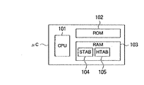
さらにマイクロコントロール部μCは、ストアードプログラム方式のマイクロコンピュータやRISCプロセッサなどから成るCPU101と、ROM(読出専用メモリ)102およびテンポラリ・メモリであるRAM103を備える。
【0170】
RAM103には、少なくともIDストリーム・テーブルSTAB104とハッシュテーブルHTAB105を記憶可能な領域が確保されている。なおIDストリーム・テーブルSTABとハッシュテーブルHTABの構成と用途は、前記図4〜図6に関して為された説明を援用する。
【0171】
ROM102には、主制御手段PRg11、ポインタ第2制御手段PRg12、メモリ転送第2制御手段PRg13の各手段が、いずれもマイクロコンピュータやRISCプロセッサによって読出・実行可能なプログラムとして格納されている。以下は各手段の概要であり、その構成の詳細は前記各実施形態で為された説明を援用する。
【0172】
主制御手段PRg11は、全体の動作を監視制御するとともに、最上段の第1段メモリM1−jから所定の読出順序に従いデータを読出してデータストリームとする。
【0173】
メモリ転送第1制御手段とメモリ転送第2制御手段PRg13は、各段のメモリにおいて、上段側メモリが存在し、且つ上段側メモリから読出順序が更に後のデータの転写要求を受けると、当該メモリに記録されたデータ中の少なくとも部分集合を上段側メモリへ転写するとともに、データ転写を受けた当該メモリの記録内容を更新する。
【0174】
ポインタ第1制御手段は、最上段メモリに記録されたデータ中で、読出順序が最後のデータ(またはその予定読出時刻)と、現在出力中のデータ(または現在時刻)との間に存在するデータ数(または時間差)を点検して第1データ数(または第1時間差)とし、当該第1データ数(または第1時間差)が所定の下限データ数(または下限時間差)に等しいか又は少ないと、下段側メモリへ読出順序が更に後のデータの転写要求を行う。
【0175】
ポインタ第2制御手段PRg12は、上段側メモリおよび下段側メモリが存在する場合に上段側のメモリへ転写したデータ中の読出順序が最後のデータ(またはその予定読出時刻)と、現在当該メモリに記録されているデータ中で読出順序が最後のデータ(または現在時刻)との間のデータ数(または時間差)を点検して第2データ数(または第2時間差)とし、第2データ数(または第2時間差)が所与の最低データ数(または最低時間差)に等しいか又は少ないと、さらに下段側のメモリへ読出順序が更に後のデータの転写要求を行う。
【0176】
なお主制御手段PRg11は、制御バス252を介してSCSIコントローラ202−i、バッファブロック203−i、DMAコントローラ281−j、処理ブロック290−j、およびI/Oコントローラ284−jと接続されており、上記の制御に加えて、適宜、それらを制御する機能を併設しており、それぞれ対応するソフトウェアプログラムが記憶されている。
【0177】
上記のように本実施形態に係るビデオデータ編集システムEDSは、主制御手段PRg11、ポインタ第1制御手段とポインタ第2制御手段PRg12、メモリ転送第1制御手段とメモリ転送第2制御手段PRg13の動作により、最下段のデータストレージ装置において再生遅延が発生しても、下段側のバッファメモリにおいて吸収され、且つメモリ転送制御手段によって再生データが下段側バッファメモリから上段側バッファメモリへ順に転写され、その都度、記録内容が更新されることにより、上段側バッファメモリにおいて常に再生データを確保することができる。しかも転写の時期を、データ数基準または時間差基準のポインタ第1および第2制御手段によって第1データ数および第2データ数、または第1時間差および第2時間差に基づき管理するから、再生データの準備に途切れが生じることがなく、途切れのない連続したストリームを再生することができる。
この結果、遅延による画像や音声の途切れがない円滑な編集が可能になる。
【0178】
【発明の効果】
以上の通り本発明によれば、プレイポインタの指定により第1段バッファメモリのデータフレームを再生して再生データストリームを出力する際に、プレイポインタが第1のプロセス対象の両端にある順方向駆動領域又は逆方向駆動領域のデータフレームを再生し始めた時、次のデータフレームの転送を、第2バッファメモリから、プレイポインタによる再生速度より速い転送速度で受けて、当該次のデータフレームによって第1のプロセス対象を設定し直すと共に、これに応動して第2段バッファメモリの順方向駆動領域又は逆方向駆動領域のデータフレームを記録メディアから読み出して更新するようにしたことにより、読み出し速度の遅い記録メディアのデータフレームを常に第1段バッファメモリ及び第2段バッファメモリの階層構造内に準備しておくことができ、これにより途切れさせることなく記録メディアのデータフレームに基づく再生データストリームを出力することができる。
【図面の簡単な説明】
【図1】本発明に係る階層型バッファメモリの一実施形態の構造図である。
【図2】本発明に係るデータ再生装置の一実施形態のブロック構成図である。
【図3】図2に示すデータ再生装置におけるデータ転写の流れの説明図である。
【図4】図2に示すデータ再生装置の主コントロール部のブロック構成図である。
【図5】図4に示すIDストリーム・テーブルの例の説明図である。
【図6】図4に示すハッシュ・テーブルの例の説明図である。
【図7】本発明に係るデータ再生方法の一実施形態の説明図である。
【図8】順方向更新動作および逆方向更新動作の処理構造の説明図である。
【図9】図7に示すデータ再生方法の過程図である。
【図10】図9に続く過程図である。
【図11】図10に続く過程図である。
【図12】図11に続く過程図である。
【図13】図12に続く過程図である。
【図14】図13に続く過程図である。
【図15】図14に続く過程図である。
【図16】図15に続く過程図である。
【図17】第1プロセスの順方向更新動作のフローチャートである。
【図18】第2プロセスの順方向更新動作のフローチャートである。
【図19】順方向更新動作および逆方向更新動作のフローチャートである。
【図20】本発明に係るシステム・オン・チップ型集積装置の一実施形態のブロック構成図である。
【図21】本発明に係る階層型バッファメモリの他の実施形態の構造図である。
【図22】本発明に係る階層型バッファメモリの記録方法の他の実施形態の説明図である。
【図23】本発明に係るデータ再生装置の別の実施形態のブロック構成図である。
【図24】本発明に係るデータ再生装置の他の実施形態のブロック構成図である。
【図25】本発明に係るビデオデータ編集システムの一実施形態のブロック構成図である。
【図26】図25に示すビデオデータ編集システムの情報・データ処理装置のブロック構成図である。
【符号の説明】
A1……階層型バッファメモリ、Bta1……逆方向駆動領域、Bta2……逆方向駆動領域、C1……記録容量、C2……記録容量、fp1……第1フロントポインタ、fp2……第2フロントポインタ、Fta1……順方向駆動領域、Fta2……順方向駆動領域、M1……第1段メモリ、M2……第2段メモリ、PP……プレイポインタ、rp1……第1リアポインタ、rp2…第2リアポインタ、Str……ストリーム[0001]
The present invention relates to a data reproduction method and a data reproduction apparatus, and more particularly to a reproduction data frame that can be output from a recording medium without interruption.
[0002]
[Prior art]
2. Description of the Related Art In a data recording / reproducing apparatus to which a randomly accessible non-linear memory medium represented by a hard magnetic disk drive (HDD) is generally applied, when the recorded moving image / audio data is reproduced, the read data is buffered. The data is transferred to the memory, further transferred to the upper layer memory, and then output from the external port.
In such a data recording / reproducing apparatus, data is recorded on a recording medium in units of frames, and a plurality of data frames are each assigned an identification number ID and managed.
[0003]
At the time of reproduction, according to a series of IDs designated by the user, that is, according to the ID stream, each data frame selectively extracted from the plurality of recording data frames is reproduced in time series in order to reproduce continuously. Output as a data stream.
[0004]
Here, since the ID stream is individually designated by each user, the configuration thereof is arbitrary, and therefore it is usually different for each reproduction. On the other hand, the recording of each ID frame on the recording medium is distributed, so that for each given ID stream, the ID frames of interest recorded in different positions on the recording medium are sequentially accessed and reproduced. There is a need to.
[0005]
Here, for example, in a disk recorder device such as a hard magnetic disk drive or an optical disk drive, the recording medium rotates and the recording / playback head performs a mechanical movement to perform an access operation. There is a reproduction delay from the generation of the reproduction start instruction at the time, that is, from the reception of the reproduction start control signal to the actual output of the reproduction data stream. Although the value of this reproduction delay varies depending on the mechanism configuration, there are cases where the reproduction delay is as small as 5 to 6 frames and as large as several tens of frames in units of one frame in the video signal.
[0006]
This delay factor depends on the time required for the reproduction process for preparing the reproduction signal transmission after receiving the reproduction request by the external signal. Specifically, when reading playback data from a recording medium such as a hard disk, in addition to the delay caused by waiting for the rotation position of the recording medium or the head seeking operation, buffering by a memory element after reading from the recording medium, and video output The overhead required for processing such as transfer to a part causes a delay.
[0007]
For this reason, in a current disk recorder apparatus that performs an operation equivalent to that of a VTR, a reproduction delay with respect to an external signal input under a protocol that guarantees the accuracy of operation time is always guaranteed to be a fixed value. This fixed reproduction delay is called an edit delay. For example, the standard disc recorder FDDR-7000 (trade name) has an edit delay of 20 frames.
[0008]
Furthermore, as a conventional technique for dealing with this reproduction delay, a predetermined number of predetermined data frames are pre-read in advance and stored in a buffer memory which can be accessed at high speed, and the access delay caused by the recording medium is apparently eliminated. There is something to do. This is a technique that can be realized by using and expanding the buffering function provided by the fact that buffering processing is indispensable for error processing and encoding / decoding processing of reproduced data.
[0009]
[Problems to be solved by the invention]
However, even in the prefetch buffering configuration as described above, for example, when each of a series of data frames arranged in chronological order is in a dispersed position, and the degree of dispersion is not constant for each ID stream, etc. Therefore, there is a problem that a predetermined amount of prefetch buffering does not always function effectively. As a result, depending on the configuration of the given ID stream and each recorded data frame position, the reaction time will also be delayed, making it difficult to guarantee a predetermined reaction time for real-time playback and variable speed playback operations. For this reason, there has been a demand for a technique that can effectively cope with a given ID stream having various configurations.
[0010]
The present invention has been made to solve the above-described problems in the prior art, and enables memory management on the playback side that is not affected by the transfer time., DeData playback methodas well asData playback deviceIs to provide.
[0011]
[Means for Solving the Problems]
In order to solve this problem, the present invention provides a data reproduction method and apparatus for sequentially outputting data frames recorded on a recording medium as a reproduction data stream via a second-stage buffer memory and a first-stage buffer memory. A predetermined number of data frames transferred from the second-stage buffer memory by the one-stage buffer memory are temporarily stored, and the reverse of the forward drive area consisting of the data frames stored at the forward end of the predetermined number of data frames. The data frame stored between the reverse drive area consisting of the data frame stored at the direction end is set as the first process target to be processed, and the data frame included in the first process target is played. Playback is performed in the order specified by the pointer and output as a playback data stream. When the play pointer starts to reproduce the data frame of the forward drive area or the backward drive area, the transfer of the data frame next to the data frame stored in the forward drive area or the backward drive area is performed by the memory. Received from the second-stage buffer memory at a transfer rate faster than the playback speed by the play pointer, and updates the next data frame as a data frame at the forward end or backward end of the first process target. The first process target having a predetermined number of data frames is reset, and the reproduction process for the new first process target is continued, and the second stage buffer memory is used to center the play pointer from the recording medium. Read a predetermined number of data frames larger than the temporary storage number of the first buffer memory, A data frame specified by the ray pointer is temporarily stored as a second process target for transfer to the first stage buffer, and the second stage buffer memory causes the first stage buffer memory to be a new first process. When the target is reset, the data frame of the forward drive area or the reverse drive area at the forward end or the reverse end of the second process target is read out from the recording medium and updated accordingly. .
[0012]
According to the recording method described above,ReRaw delayEven if there is, the reproduced data frame can be output without interruption by absorbing this.
[0035]
DETAILED DESCRIPTION OF THE INVENTION
Preferred embodiments of the present invention will be described below in detail with reference to the accompanying drawings. The embodiment described below is a part of a preferred example for showing the essential configuration and operation of the present invention. Therefore, there are cases where various limitations preferable in terms of the technical configuration may be attached. The scope of the invention is not limited to these forms unless otherwise specified in the following description.
[0036]
FIG. 1 is a structural diagram of an embodiment of a hierarchical buffer memory according to the present invention, and is a diagram modeling the concept of memory management.
As shown in FIG. 1, the hierarchical buffer memory A1 according to the present invention is a two-stage buffer memory, and is composed of a first-stage memory M1 and a second-stage memory M2. The first-stage memory M1 is an upper-stage memory and has a recording capacity C1. The second stage memory M2 is a lower stage side memory and has a recording capacity C2. Here, the recording capacity C2 is larger than the recording capacity C1, and the data access speed is higher in the upper memory than in the lower memory. Further, a lowermost recording medium (for example, a disk storage device) (not shown) exists on the lower side from the second stage memory M2.
[0037]
Transferred from a lowermost recording medium (not shown) in the order of an ID stream (not shown) arranged in chronological order in the order in which the IDs of the data frames to be reproduced are designated on the second-stage memory M2, which is a secondary buffer memory The stored data frame column is stored for the storage capacity C2. Further, on the first-stage memory M1, which is the upper-stage primary buffer memory, a column of data frames transferred from the second-stage memory M2 is stored by the storage capacity C1. Here, since the storage capacity C1 is smaller than the storage capacity C2, a subset of the columns of the data frames stored in the second stage memory M2 is transferred and stored on the first stage memory M1. Become. Therefore, the lower memory includes the upper memory. Operation is performed so that this inclusion relationship is always maintained.
[0038]
The front end of the first-stage memory M1 is a first front pointer fp1, and the rear end is a first rear pointer rp1. Further, a predetermined area inside the first front pointer fp1 is set as a forward driving area Fta1, and a predetermined area inside the first rear pointer rp1 is set as a backward driving area Bta1, and a playback pointer (play pointer) is set to these areas. When PP enters, a new transfer request is generated.
[0039]
Here, when a forward reproduction start request is generated, the play pointer PP located on the first-stage memory M1 starts to move, and the data frame transferred and stored in the first-stage memory M1 is transferred to the play pointer PP according to this movement. Are sequentially output, and a reproduction data stream Str is generated. During this time, data transfer from the second-stage memory M2 to the first-stage memory M1 is not performed, and the recorded contents of the first-stage memory M1 are not updated.
[0040]
In this way, the data frame is pointed to the play pointer PP and sequentially output. When the play pointer PP eventually moves to the forward drive area Fta1 provided at the front end of the first-stage memory M1, the first front pointer fp1. From the second-stage memory M2 to the first-stage memory M1, and a further data frame is transferred from the second-stage memory M2, and the recorded contents of the first-stage memory M1 are recorded. Updated. At the same time, the first front pointer fp1 and the first rear pointer rp1 are also updated.
[0041]
The data transfer from the second-stage memory M2 to the first-stage memory M1 is sufficiently faster than the movement speed of the play pointer PP, that is, the data reproduction speed. Therefore, the first transfer without causing any trouble in the movement of the play pointer PP. The recorded contents of the stage memory M1 are updated. That is, while the play pointer PP reproduces the first data frame in the forward drive area Fta1, the recorded content of the first stage memory M1 is updated, and this forward drive area Fta1 is also updated and logically updated. Move forward. Similarly, the first front pointer fp1 and the first rear pointer rp1 are also updated and moved logically forward. As a result, the data frame located in the old forward drive area Fta1 that is being reproduced by the play pointer PP is no longer located in the new forward drive area Fta1, and moves logically backward. A time margin is generated until the play pointer PP at the current position moves and reaches the end of the new forward drive area Fta1.
[0042]
As described above, the first stage memory M1 logically moves the reproduction data stream Str forward by this update, and the update is performed each time the play pointer PP reaches the forward drive area Fta1. Since this is done immediately, the moving play pointer PP does not reach the first front pointer fp1, and prefetching is always ensured by the amount of the forward drive area Fta1. As a result, the movement of the play pointer PP is not applied to the end of the first stage memory M1, so that the reproduction data stream Str is not interrupted.
[0043]
As apparent from the above, the first front pointer fp1 and the first rear pointer rp1 are intermittently updated. On the other hand, the first front pointer fp1 and the first rear pointer are also updated on the second-stage memory M2. rp1 moves forward intermittently.
[0044]
When the above operation is repeated and the first front pointer fp1 moves to the forward drive area Fta2 provided at the front end of the second stage memory M2, the lowermost memory (disk storage device) to the second stage memory M2 is here. ) From the lowermost memory, and the recorded contents of the second memory M2 are updated. At the same time, the second front pointer fp2 and the second rear pointer rp2 are also updated.
[0045]
By this update, the second-stage memory M2 logically moves the reproduction data stream Str forward. In addition, the second stage memory M2 is updated every time the first front pointer fp1 that moves intermittently reaches the forward drive area Fta2, so the first front pointer fp1 that moves is the first one. 2 The front pointer fp2 is not reached, and prefetching is always ensured by the amount of the forward drive area Fta2. As a result, the movement of the first front pointer fp1 is not applied to the end of the second-stage memory M2, so that the transfer from the second-stage memory M2 to the first-stage memory M1 is not interrupted.
[0046]
Further, the recording capacity C2 of the second-stage memory M2 is larger than the recording capacity C1 of the first-stage memory M1, so that the forward drive area Fta2 can be secured larger than the forward drive area Fta1. This is also true in the case of a multi-stage configuration, and the access time of each memory on the upper stage is faster than the access time of the recording medium on the lower stage.
[0047]
Therefore, in the configuration of the present invention in which the data frame is transferred to the upper stage via the multi-stage buffer memory, a large forward drive area of the lower memory can be secured, and the update interval becomes longer, so that the time is increased by the hierarchical configuration. Since there is a sufficient margin, for example, even if the playback data frame is distributed and arranged on the lowermost disk storage device and the seek time varies, this irregular delay can be absorbed sufficiently.
[0048]
As a result, even when various ID streams are instructed, there is no interruption in the reproduction of the uppermost data frame, so that the reproduction delay in the lowermost memory is absorbed and a continuous reproduction data stream is generated. It becomes possible to output stably.
[0049]
Although the above has been described with respect to the forward reproduction operation, the same operation is performed for the backward reproduction operation. The size (number of data or time difference) of the forward drive areas Fta1 and Fta2 and the reverse drive areas Bta1 and Bta2 is calculated from the moving speed of the play pointer PP and the expected value of the transfer time. It can be set arbitrarily depending on the situation.
[0050]
FIG. 2 is a block diagram of an embodiment of the data reproducing apparatus according to the present invention.
FIG. 3 is an explanatory diagram of the flow of data transfer in the data reproducing apparatus shown in FIG.
FIG. 4 is a block diagram of the main control unit of the data reproducing apparatus shown in FIG.
FIG. 5 is an explanatory diagram of an example of the ID stream table shown in FIG.
FIG. 6 is an explanatory diagram of an example of the hash table shown in FIG.
[0051]
As shown in FIG. 2, the data reproducing device DRP according to the present embodiment includes a data storage device DS, a main control unit μC, and a sub-control unit DSP using a digital signal processor, and data read from the data storage device DS. Is output outside the apparatus as an output data stream Str.
[0052]
The data storage device DS includes a third-stage memory M3 composed of a magnetic or optical disk recording medium, and a disk controller Dcnt.
[0053]
The main control unit μC is a
[0054]
The sub-control unit DSP includes a
[0055]
The moving image / audio data is stored in the hard disk as the third stage memory M3, and this data can be transferred to the second stage memory M2, which is a buffer memory, via the SCSI bus. Further, data can be transferred between the second-stage memory M2 and the first-stage memory M1 via the DMA bus, and the data transferred to the first-stage memory M1 is output from the external I / O port. .
[0056]
A plurality of data frames (each ID is 23, 98, 424, 436, 532, 600, 753) are recorded in the third-stage memory M3. During reproduction, the data frame selectively read from the third-stage memory M3 is transferred to the second-stage memory M2 via the SCSI bus managed by the SCSI bus control function of the memory transfer second control means Prg13. Further, the data is transferred from the second-stage memory M2 to the first-stage memory M1 via the DMA bus managed by the DMA bus control function of the memory transfer first control means Prg2.
[0057]
Thus, a two-level buffer memory structure is realized by the first-stage memory M1 and the second-stage memory M2, and a three-level memory structure is realized by adding the lowest-level third-stage memory M3. Here, the data capacity of the first-stage memory M1, the second-stage memory M2, and the third-stage memory M3 is the largest in the hard disk medium of the third-stage memory M3, and then the second-stage memory M2, each of which is a semiconductor memory, This is the order of the first stage memory M1. On the other hand, regarding the access speed, the first-stage memory M1 is the fastest, followed by the second-stage memory M2 and the lowest-stage third-stage memory M3 (hard disk).
[0058]
The above three-level memory structure will be further described with reference to FIG.
The memory includes a first layer Ly1, a second layer Ly2, and a third layer Ly3 from the upper side to the lower side.
[0059]
In the disk storage device as the third-stage memory M3 belonging to the lowermost third layer Ly3, data blocks ID23, ID98, ID424, ID436, ID532, ID600, and ID753 are recorded on the disk recording medium (HDD). .
[0060]
Data recorded on a disk recording medium is generally managed in a predetermined unit. For example, video data is a video block of one frame unit (about 1 MByte), and audio data is an audio block of about 0.6 seconds (32 k samples). These blocks can be collectively handled as data blocks, but in the case of video data, they may be described as data frames.
[0061]
Each data block uniquely corresponds to an ID (block ID), and each block ID and recording position information (address) on the disk recording medium (HDD) are recorded on the disk as a hash table HTAB shown in FIG. Stored in a predetermined area on the medium at the time of recording.
[0062]
In the hash table HTAB, a block ID j, an entry address EAdrj of the block, and a recording length LNgj (all j = 1, 2,..., 753,...) Are recorded.
This hash table HTAB is transferred from the disk recording medium to the
[0063]
In the data stream Str to be reproduced, the data blocks ID600, ID23, ID98, ID753, ID436, ID532, and ID424 are read and reproduced in this reading order. The selection and order of the reproduction IDs are input to the system by the user and managed by the main control means PRg11. The main control means
[0064]
In the ID stream table STAB, IDs of data blocks to be reproduced are arranged in the order of reproduction. At the time of reproduction, the corresponding block IDs are referred from the hash table HTAB in the order indicated by the ID stream, and the entry address EAdrj corresponding to this block is entered, and the recording length LNgj is read out. When this reading is completed, the process returns to the ID stream table STAB and the next data block in the reproduction order is processed in the same manner.
As a result, a plurality of data blocks are successively reproduced in time series from the corresponding addresses on the disk recording medium, thereby forming one continuous reproduction video stream. This is suitable for reproduction of moving image data such as a movie.
[0065]
In addition, in addition to the ID for each data block, the reproduction start time of the data block may be set as a time code in the ID stream table STAB.
[0066]
As shown in FIG. 4, the ID stream table STAB and the hash table HTAB described above are temporarily stored in the
[0067]
Based on this ID stream table, the main control unit μC, as shown in FIG. 3, converts the data blocks ID98, ID753, ID436, which are part of the corresponding data block, from the third-stage memory M3 to the second-stage memory M2. Transfer to As a result, the data blocks ID98, ID753, and ID436 are transferred from the third-stage memory M3 and recorded in the second-stage memory M2 belonging to the second layer Ly2.
[0068]
Further, among the data blocks recorded in the second-stage memory M2, a part of ID753 and ID436 is transferred to the first-stage memory M1 and recorded by the sub-control unit DSP as shown in the figure. Since the first-stage memory M1, which is the uppermost stage, is a semiconductor cache memory, its access time is fast, and the reproduction data stream Str can be read out and output without delay.
[0069]
The code IDst in the figure is an ID stream in which image / audio data block IDs are arranged in the order of reproduction, and the image / audio data of the corresponding data block is output and reproduced by moving the play pointer PP thereon. Here, the play pointer PP is a pointer that immediately responds to an operation and moves back and forth on the ID stream IDst, and video data or audio data of a data block corresponding to the passing position is output to an external port. . In FIG. 3, the play pointer PP is on the
[0070]
Thus, actual image / audio data corresponding to the block ID registered in the ID stream IDst is stored in the third-stage memory (hard disk) M3.outputIn order to output the data stream Str without interruption, memory management is performed so that the video data or audio data of the corresponding ID is prepared in the first-stage memory M1 which is the uppermost stage before the play pointer PP arrives. It is necessary to
[0071]
The principle of this memory management operation is to maintain the “relationship that the data in the lower memory includes the data in the upper memory in the stream”. That is, data is always prepared so as to include the play pointer PP in the first stage memory M1, and data including data prepared in the first stage memory M1 is always prepared in the second stage memory M2. To do.
In this system, the hard disk which is the third-stage memory M3 is the final storage area, and all the data is stored here. The relationship included in the data is established.
[0072]
In the above memory management, the main control unit PRg11, the pointer second control unit PRg12, and the memory transfer second control unit Prg13, all of which are read by the
[0073]
FIG. 7 is an explanatory diagram of an embodiment of a data reproduction method according to the present invention.
FIG. 8 is an explanatory diagram of the processing structure of the forward update operation and the backward update operation of the data reproduction method shown in FIG.
Further, FIGS. 9 to 16 are process diagrams of the forward update operation of the data reproduction method shown in FIG.
[0074]
Hereinafter, a data reproduction method will be described with reference to FIG. 7, and FIG. 1 will be cited as appropriate.
In FIG. 7, the range between the first front pointer fp1 and the first rear pointer rp1 in the data stream Str corresponds to the area mapped in the first stage memory M1 in FIG. The play pointer PP is always placed in this area.
A forward driving area Fta1 and a backward driving area Bta1 are set in the inner direction of each of the first front pointer fp1 and the first rear pointer rp1.
[0075]
A range between the second front pointer fp2 and the second rear pointer rp2 corresponds to an area mapped in the second stage memory M2 in FIG. As described above, this area includes the area mapped to the first-stage memory M1. Therefore, the first front pointer fp1 and the first rear pointer rp1 are managed so as to be always in this area.
[0076]
Further, a forward driving area Fta2 and a backward driving area Bta2 are set in the inner direction of each of the second front pointer fp2 and the second rear pointer rp2. The forward direction drive region Fta2 and the reverse direction drive region Bta2 are set wider than the forward direction drive region Fta1 and the reverse direction drive region Bta1, respectively.
[0077]
As playback progresses, the play pointer PP moves in the direction of the first front pointer fp1. When the play pointer PP reaches the forward drive area Fta1, the data mapped in the first stage memory M1 is updated in the forward direction, and the first front pointer is updated. The positions of fp1 and the first rear pointer rp1 are updated in the forward direction. As a result, the forward direction drive area Fta1 and the reverse direction drive area Bta1 are also updated.
The mapping contents, pointers, and update of the drive area in the first-stage memory M1 are managed by the assigned process pr1.
[0078]
Here, the update of the mapping contents of the first-stage memory M1 is a transfer from the buffer memory forming the second-stage memory M2 to the buffer memory forming the first-stage memory M1, and the transfer amount is a frame unit in the case of video. In the case of audio, it is a sample unit (word).
[0079]
On the other hand, when the updated first front pointer fp1 reaches the forward drive area Fta2 of the second stage memory M2, the data mapped in the second stage memory M2 is updated in the forward direction, and the second front pointer fp2 and the second
The mapping contents of the second-stage memory M2, the pointer, and the update of the drive area are managed by the assigned process pr2.
[0080]
Here, the update of the mapping contents of the second-stage memory M2 is a transfer from a recording medium such as a magnetic disk to the buffer memory forming the second-stage memory M2, and the transfer amount is a page size (Blockback) that the system manages the hard disk. ) Is quantized.
[0081]
The processes pr1 and pr2 operate independently, but both processes operate on a common simple principle. That is, in these processes, the range between the inner first front pointer fp1 and the first rear pointer rp1 does not jump out the outer range between the second front pointer fp2 and the second rear pointer rp2. Manage to include.
[0082]
The process pr1 moves the first front pointer fp1 and the first rear pointer rp1 at both ends, and the process pr2 moves the second front pointer fp2 and the second rear pointer rp2 at both ends. Here, moving each front pointer fp forward (forward direction) means securing and transferring a new area, and moving backward (reverse direction) means releasing the old area.
[0083]
Conversely, moving the rear pointer rp forward means releasing the old area, and moving backward means securing and transferring the new area. The common operating principle of these processes is that "if the inner pointer approaches, move your pointer away, and conversely, if the inner pointer moves away, move your own boyter".
[0084]
The forward update operation is performed as described above. As shown in FIG. 8, the first process pr1 shifts the front pointer fp1 and the rear pointer rp1 forward, and notifies the second position pr2 of the new position information. It is executed by doing.
On the other hand, the backward update operation is similarly executed by shifting the front pointer fp1 and the rear pointer rp1 backward and notifying the second process pr2 of the new position information.
[0085]
In the above, the pointer management can be configured in two types, based on the number of data basis and based on the time difference basis.
In the data number standard, for example, in the data recorded in each stage memory, the number of data existing between the last read order data and the data currently being output is checked and managed based on this data number.
[0086]
On the other hand, the time difference criterion is, for example, by calculating the time difference between the scheduled read time of the last data in the reading order in the data recorded in each stage memory and the current time during reading and reproduction of the intermediate data. Manage based on. Any reference configuration can be applied in the present invention.
[0087]
Returning to FIG. 2, the operation of each means will be described.
The memory transfer first control means PRg2 executes transfer management from the second-stage memory M2 to the first-stage memory M1, and mapping of data between the first front pointer fp1 and the first rear pointer rp1 of the first-stage memory M1. To do.
[0088]
The control means PRg4 manages the position of the play pointer PP and controls so that the play pointer PP is always within the area between the first front pointer fp1 and the first rear pointer rp1. Further, it exchanges information necessary for control with the main control means PRg11.
[0089]
The pointer first control means PRg1 sets and updates the forward drive area Fta1 and the backward drive area Bta1 in the inner directions of the first front pointer fp1 and the first rear pointer rp1, respectively. Further, in the case of the configuration based on the number of data, the pointer first control means PRg1 determines the number of data existing between the data read last in the data recorded in the uppermost memory and the data currently being output. If the first data number is equal to or less than the predetermined lower limit data number as a result of checking the first data number and the play pointer PP moving in the direction of the first front pointer fp1 and reaching the forward drive area Fta1. Then, a data transfer request is issued to the lower memory in the later reading order.
[0090]
Further, when the pointer first control means PRg1 has a time difference reference configuration, among the data recorded in the uppermost memory, the scheduled read time of the last data in the reading order and the current time when the intermediate data is read and reproduced. Is calculated as the first time difference, and the play pointer PP moves in the direction of the first front pointer fp1 to reach the forward drive area Fta1, so that the first time difference is equal to or shorter than the predetermined lower limit time difference. Then, a data transfer request is issued to the lower memory in the later reading order.
[0091]
The data output means PRg3 outputs data in accordance with a predetermined reading order from the first stage memory M1, which is the uppermost stage memory.
[0092]
The memory transfer second control means PRg13 manages the transfer from the third-stage memory M3 to the second-stage memory M2 by sending a control signal to the disk controller Dcnt of the data storage device DS, and the second transfer of the second-stage memory M2. Data mapping between the front pointer fp2 and the second rear pointer rp2 and transfer management of at least a subset of the data recorded in the second stage memory M2 to the first stage memory M1 are executed.
[0093]
The main control means PRg11 performs control so that the first front pointer fp1 and the first rear pointer rp1 are always within the area between the second front pointer fp2 and the second rear pointer rp2. Furthermore, the control means PRg4 exchanges information necessary for control.
[0094]
The pointer second control means PRg12 sets and updates the forward drive area Fta2 and the reverse drive area Bta2 in the inner directions of the second front pointer fp2 and the second rear pointer rp2, respectively. Further, when the pointer second control means PRg12 is based on the number of data, if there is an upper memory and a lower memory, the last read order in the data transferred to the upper memory is recorded in the current memory. The number of data between the read data and the last data in the reading order is inspected to obtain the second data number, the first front pointer fp1 moves to reach the forward drive area Fta2, and the second data number When the number is equal to or less than a given minimum number of data, a transfer request is made to transfer data to the memory on the lower side further in the reading order.
[0095]
Alternatively, when the pointer second control means PRg12 is based on a time difference, when there is an upper memory and a lower memory, the read-out time of the last data in the data transferred to the upper memory and the current memory The time difference from the scheduled read time of the last data in the read order is calculated as the second time difference, and the first front pointer fp1 moves to reach the forward drive area Fta2. When the second time difference is equal to or shorter than the given minimum time difference, a further transfer request is made to the memory in the lower stage further later.
[0096]
Hereinafter, each process of the forward update operation of the data reproduction method shown in FIG. 8 will be described with reference to FIGS. 9 to 12 show the operation process of the first process pr1, and FIGS. 13 to 16 show the operation process of the second process pr2.
[0097]
In FIG. 9, the first process pr1 on the first stage memory M1 holds a play pointer PP as a pointer within the range. The play pointer PP moves to the forward drive area Fta1 as the reproduction progresses.Sub-control sectionThis is done by the DSP and notified by an interrupt.
[0098]
As shown in FIG. 10, when the play pointer PP reaches the forward drive area Fta1, a temporary first process Tpr1 moved in the forward direction is set as shown by a dotted line in FIG. The first front pointer fp1 and the first rear pointer rp1 also move in the forward direction, and the provisional first front pointer Tfp1 and the provisional first rear pointer Trp1 are set, respectively.
[0099]
Since the data between the provisional first front pointer Tfp1 and the current first front pointer fp1 does not exist on the current first-stage memory M1, the data in the meantime is transferred from the second-stage memory M2. With this transfer, the data between the current first rear pointer rp1 and the temporary first rear pointer Trp1 is released / discarded. Here, when the first-stage memory M1 has a ring buffer structure, the rear portion is automatically released by the transfer to the front portion.
Thereby, the data mapping on the first stage memory M1 is updated.
[0100]
As a result of the update as described above, as shown in FIG. 12, the new first front pointer fp1 ′, the new first rear pointer rp1 ′, and the new first process pr1 ′ are changed, and the drive region is also updated. Thus, a forward new drive region Fta1 ′ and a reverse new drive region Bta1 ′ are obtained. As a result, the distance between the play pointer PP and the new first front pointer fp1 'increases, and the play pointer PP can continue to move without trouble, so that the reproduction data stream Str is not interrupted.
[0101]
Next, in FIG. 13, the second process pr2 on the second-stage memory M2 holds a first front pointer fp1 and a first rear pointer rp1 as pointers within the range. Since the first front pointer fp1 and the first rear pointer rp1 are updated as described above, they move each time they are updated. Eventually, as shown in FIG. 14, the new first front pointer fp1 'reaches the forward drive area Fta2.
[0102]
When the new first front pointer fp1 ′ reaches the forward drive area Fta2, the provisional second process Tpr2 moved in the forward direction is set as indicated by the dotted line in FIG. 15, and accordingly, the second front pointer is set. fp2 and the second rear pointer rp2 also move in the forward direction, and the provisional second front pointer Tfp2 and the provisional second rear pointer Trp2 are set, respectively.
[0103]
Since the data between the provisional second front pointer Tfp2 and the current second front pointer fp2 does not exist on the current second-stage memory M2, the data in the meantime is transferred from the third-stage memory M3. With this transfer, data between the current second rear pointer rp2 and the provisional second rear pointer Trp2 is released / discarded.
Thereby, the data mapping on the second stage memory M2 is updated.
[0104]
As a result of the update as described above, as shown in FIG. 16, the new second front pointer fp2 ′, the new second rear pointer rp2 ′, and the new second process pr2 ′ are changed, and the drive region is also updated. Thus, a forward new drive region Fta2 ′ and a reverse new drive region Bta2 ′ are obtained. As a result, the distance between the new first front pointer fp1 'and the new second front pointer fp2' increases, and the transfer from the second-stage memory M2 to the first-stage memory M1 can be continued without any trouble. Therefore, the output of the reproduction data stream Str from the first stage memory M1 is not interrupted.
[0105]
FIG. 17 is a flowchart of the forward update operation of the first process pr1, and FIG. 18 is a flowchart of the forward update operation of the second process pr2.
The operation will be described below with reference to both figures.
[0106]
In the forward update operation of the first process pr1, one frame is sent out from the first stage memory M1 as a reproduction data stream Str (step S1). Next, the play pointer PP is moved by one frame (step S2).
[0107]
Here, it is checked whether or not the play pointer PP has reached the forward drive area Fta1 (step S3), and if it has reached, the first front pointer fp1 is moved to the provisional first front pointer Tfp1 (step S4). Further, the first rear pointer rp1 is moved to be a provisional first rear pointer Trp1 (step S5).
[0108]
Next, the first process pr1 is set as a provisional first process Tpr1 (step S6). Subsequently, the difference block between the provisional first front pointer Tfp1 and the first front pointer fp1 is transferred from the second-stage memory M2 to the first-stage memory M1 (step S7).
[0109]
The provisional first front pointer Tfp1 and the provisional first rear pointer Trp1 are set to the new first front pointer fp1 ′ and the new first rear pointer rp1 ′, respectively, and the provisional first process Tpr1 is set to the new first process pr1 ′. (Step S8).
[0110]
The forward drive area and the reverse drive area are updated to Fta1 'and Bta1' (step S9). Further, the information of the new first front pointer fp1 'and the new first rear pointer rp1' is sent to the second process pr2 (step S10).
[0111]
The forward update operation of the second process pr2 checks whether the updated new first front pointer fp1 ′ and the new first rear pointer rp1 ′ have been accepted (step S21). It is checked whether or not the front pointer fp1 ′ has reached the forward drive area Fta2 (step S22).
[0112]
When the new first front pointer fp1 ′ reaches the forward drive area Fta2, the second front pointer fp2 is moved to the provisional second front pointer Tfp2, and the second rear pointer rp2 is moved to the provisional second rear pointer Trp2. (Step S23).
[0113]
Next, the difference block portion between the provisional second front pointer Tfp2 and the second front pointer fp2 is transferred from the disk recording medium of the third stage memory M3 to the second stage memory M2 (step S24).
[0114]
The provisional second front pointer Tfp2 and the provisional second rear pointer Trp2 are set to the new second front pointer fp2 ′ and the new second rear pointer rp2 ′, respectively, and the provisional second process Tpr2 is set to the new second process pr2 ′. (Step S25).
Then, the forward drive area and the reverse drive area are updated to Fta2 'and Bta2' (step S26).
[0115]
FIG. 19 is a flowchart of the forward update operation and the backward update operation. When generation of the notification input is confirmed (step S31), it is confirmed whether the position notification from the process pr1 is the first front pointer fp1 or the first rear pointer rp1 (step S32), and the first front pointer fp1. If it is a notification, the forward movement is made. Next, it is checked whether the distance between the first front pointer fp1 and the second front pointer fp2 is within the threshold value (step S33). If the distance is within the threshold value, the first front pointer fp1 approaches the second front pointer fp2. The second front pointer fp2 is moved forward by one block to update the position (step S34).
[0116]
On the other hand, if it is not within the threshold value in step S33, it is checked whether the distance between the first front pointer fp1 and the second front pointer fp2 is larger than one block (step S35). If the distance is smaller than one block, the process returns to step S31. If the distance is greater than one block, the second front pointer fp2 is moved backward by one block (step S36).
[0117]
On the other hand, if the position notification is the first rear pointer rp1 in step S32, the reverse movement is performed thereafter. Next, it is checked whether the distance between the first rear pointer rp1 and the second rear pointer rp2 is within the threshold (step S37). If the distance is within the threshold, the second rear pointer rp2 is moved backward by one block to update the position. (Step S38).
[0118]
On the other hand, if it is not within the threshold value in step S37, it is checked whether the distance between the first rear pointer rp1 and the second rear pointer rp2 is larger than one block (step S39). If the distance is smaller than one block, the process returns to step S31. If the distance is greater than one block, the second rear pointer rp2 is moved forward by one block (step S40).
[0119]
Next, an embodiment of a computer-readable recording medium according to the present invention will be described.
The computer-readable recording medium according to the present embodiment can be provided by being recorded in a read-only semiconductor memory (ROM) chip, for example, and is applied to a data reproducing apparatus having a predetermined system configuration.
[0120]
An applicable data reproducing apparatus includes at least the following.
1. Computer.
2. A data storage device capable of sequentially reading a plurality of data recorded on a built-in or external recording medium in a predetermined order from a specified start address.
3. A buffer memory and a memory controller having at least one stage and capable of reading at a higher speed than the reading speed of the data storage device and having a capacity capable of storing at least a part of a stream output from the data storage device.
[0121]
The recording medium according to the present embodiment includes a ROM chip or the like, and at least a memory transfer control unit, a data output unit, a data number-based pointer first control unit, and a data number-based pointer second control as programs that can be read and executed by a computer. Means are recorded.
[0122]
The memory transfer control means is configured such that when there is an upper memory in each stage of the computer, and a transfer request for data further in the reading order is received from the upper memory, at least a part of the data recorded in the memory This is a program that functions to transfer the set to the upper memory and to update the recorded contents of the memory that has received the data transfer.
[0123]
The data output means is a program that causes the computer to function to output data in accordance with a predetermined reading order from the uppermost memory.
[0124]
The pointer number first control means based on the number of data checks the computer to check the number of data existing between the last data in the reading order in the data recorded in the uppermost memory and the data currently being output. When the number of data is one and the first number of data is equal to or less than a predetermined lower limit number of data, this is a program that causes the lower memory to function so as to make a transfer request for data that is later in the reading order.
[0125]
The second control means based on the number of data records the last read data in the data transferred to the upper memory when the upper memory and the lower memory exist in the computer, and the current data is recorded in the memory. If the number of data between the last data in the read data is inspected and set as the second data number, and this second data number is equal to or less than the given minimum data number, the further lower side This is a program that functions to make a transfer request for data whose reading order is further to the memory.
[0126]
The memory transfer control means, the data output means, the data number-based pointer first control means, and the data number-based pointer second control means recorded as programs on the computer-readable recording medium are executed by a computer. Then, even if a playback delay occurs on the lower side, the recording capacity is absorbed in the lower side memory, and the playback data is sequentially transferred from the lower side memory to the upper side memory by the memory transfer control means. Is updated, the reproduction data can always be secured in the upper memory. Moreover, since the transfer timing is managed by the first and second control means based on the number of data based on the first data number and the second data number, there is no interruption in the preparation of the reproduction data, and the reproduction is performed by the data output means. Data can be output continuously.
[0127]
In addition, the above-described program has a configuration based on the number of data, but instead, a configuration based on a time difference-based program can be used. In the case of a time difference reference program, the data number reference pointer first control means and the data number reference pointer second control means are changed to a time difference reference pointer first control means and a time difference reference pointer second control means, respectively. Is done. The configurations and functions of the time difference reference pointer first control means and the time difference reference pointer second control means are the same as those shown in FIG. 2, and thus the above description is incorporated.
[0128]
FIG. 20 is a block configuration diagram of an embodiment of a system-on-chip type integrated device according to the present invention. Hereinafter, a description will be given based on FIG.
The system-on-chip integrated device SysL according to the present invention can be incorporated in the data reproducing device DRP.
[0129]
The data reproduction device DRP incorporating the system-on-chip integrated device SysL includes a data storage device DS that sequentially reads out a plurality of data recorded on a built-in recording medium in a predetermined order and outputs the data as a stream. . In this data storage device DS, a plurality of data blocks as material data are recorded and function as the lowest memory in the hierarchical memory structure.
[0130]
The system-on-chip integrated device SysL includes a processor unit CProc, a bus unit Cbus, an input / output interface unit Cio, and a first memory unit Cram that temporarily holds data, on the same chip. Each includes a second memory unit Crom that stores a program that can be read and executed by the processor unit CProc.
[0131]
The processor unit CPProc is composed of a
[0132]
The first memory unit Cram is configured as a cell of a DRAM (anytime write / read memory in which a memory holding operation is performed), and a first-stage memory M1, a second-stage memory M2, and a table TAB are developed therein.
[0133]
The second memory unit Crom is configured as a ROM (read only memory) cell. The stored program includes at least the overall control means PRg11 ', the pointer first control means PRg1, the memory transfer first control means PRg2, the pointer second control means PRg12, the memory transfer second control means PRg13, and the bus control means PRg20. The bus control means PRg20 includes a SCSI bus, DMA bus, control bus, and I / O bus controller.
[0134]
In addition to the above-described means, the second memory unit Crom is provided with other means (not shown) such as parity processing, encoding / decoding processing means, and the like.
[0135]
The overall control means PRg11 ′, the pointer first control means PRg1, the memory transfer first control means PRg2, the pointer second control means PRg12, and the memory transfer second control means PRg13 are read by the
[0136]
The overall control means PRg11 'performs control so that the first front pointer fp1 and the first rear pointer rp1 are always within the area between the second front pointer fp2 and the second rear pointer rp2. Further, the position of the play pointer PP is managed, and control is performed so that the play pointer PP is always within the area between the first front pointer fp1 and the first rear pointer rp1. Further, the data is read from the first-stage memory M1, which is the uppermost memory, in accordance with a predetermined reading order, and is output to the input / output interface unit Ci.
[0137]
The configuration and function of the pointer first control means PRg1, the memory transfer first control means PRg2, the pointer second control means PRg12, and the memory transfer second control means PRg13 are all the same as those in the above-described embodiment, and thus the description above. And the above figures are incorporated.
[0138]
As described above, in the system-on-chip type integrated system SysL of the present embodiment, each unit configured by a program controls the data storage device DS based on the determination or calculation to realize a predetermined function. Thus, by incorporating this system-on-chip type integrated device SysL, for example, a device having the function shown in FIG. 2 can be easily manufactured.
[0139]
Usually, each of the above-described units (cores) of the system-on-chip type integrated device is arranged and formed on a single substrate as a plurality of IPs, and is called a system LSI (System LSI).
[0140]
FIG. 21 is a structural diagram of another embodiment of a hierarchical memory according to the present invention. FIG. 22 is an explanatory diagram of another embodiment of the hierarchical memory recording method according to the present invention.
[0141]
As shown in both figures, the hierarchical memory A2 according to the present embodiment has a two-layer configuration realized by a first-stage memory M1 ′ functioning as a buffer memory and a base memory BM that is a lowermost recording medium. Yes.
[0142]
The base memory BM records a plurality of data on a disk-shaped, tape-shaped or card-shaped recording medium, and selectively transfers a part of the recorded plurality of data onto the first-stage memory M1 ′. Data is sequentially read from the first stage memory M1 ′ according to a predetermined reading order to form a reproduction data stream Str. The first stage memory M1 ′ has a forward drive region Fta1 ′ and a reverse drive region Bta1 ′. Is set. Further, the play pointer PP moves on the first stage memory M1 '.
[0143]
When the number of data between the data in the last reading order and the data currently being reproduced in the data on the first stage memory M1 ′ is equal to or less than the predetermined number, the base memory BM changes to the first stage memory M1. Data to which the reading order is further transferred is transferred to ', and the number of data between the last data in the reading order and the data currently being reproduced is greater than the given number of data. Or the contents of the first stage memory M1 ′ are updated until they become equal. Therefore, the function of the hierarchical memory A2 is in accordance with the function of the hierarchical buffer memory A1 shown in FIG.
[0144]
FIG. 23 is a block diagram of another embodiment of the data reproducing apparatus according to the present invention. The data reproducing apparatus DRP2 of this embodiment includes a disk array in which a plurality of storage modules M3 'each composed of a plurality of hard disks are coupled, and a plurality of second modules connected to the hard disk and the
[0145]
The storage module M3 ′ functions as the lowermost recording medium, and the second-stage memory M2 and the first-stage memory M1 each comprising a buffer memory form a hierarchical memory structure, and the functions and operations shown in FIG. Is realized.
A plurality of storage modules M3 ', a plurality of second-stage memories M2, and a plurality of first-stage memories M1 can output a plurality of data streams.
[0146]
FIG. 24 is a block diagram showing another embodiment of the data reproducing apparatus according to the present invention. Data reproduction device DRP of this embodiment3Is a variation of FIG. 23, which is slower than the hard disk, but has a larger storage capacityM4 (for example, tape-based data storage) is arranged in the lower layer of a storage module M3 'using a hard disk. Also in this configuration, a smooth reproduction state can be realized without waiting in a normal reproduction operation by the same operation as described above.
[0147]
FIG. 25 is a block diagram of an embodiment of a video data editing system according to the present invention.
FIG. 26 is a block diagram of the information / data processing apparatus of the video data editing system shown in FIG.
[0148]
As shown in FIG. 25, the video data editing system EDS of the present embodiment is such that video data is input to the
[0149]
Further, the
[0150]
On the other hand, the
[0151]
The
[0152]
Furthermore, the information / data processing device SDP can exchange commands and information with the
[0153]
The information / data processing device SDP records multi-channel video data on a recording medium (for example, hard disk medium HD) of a built-in data storage, and records a plurality of the recorded video data from a specified start address. A function of sequentially reading out in order and outputting as a video stream is provided.
[0154]
Data recorded on the recording medium is managed by the
[0155]
Further, each of these data blocks is uniquely associated with an ID (block ID). In the CPU memory space, an ID and a correspondence table (hash table) of addresses on the hard disk medium (HD), for example, are placed. It has been. Since the real-time property is important, this correspondence table is resident in the real memory RAM.
[0156]
The ID stream is an arrangement (array) of the block IDs, and can be arbitrarily created, changed, or deleted by the user. That is, video data is recorded / reproduced / edited by the user setting / updating an ID stream from an external terminal (for example, a host computer). The ID stream set / updated in this way is held as an ID stream file in the real memory RAM.
[0157]
At the time of reproduction, the correspondence table is referred based on the order indicated by the ID stream, and the data block of the corresponding ID is sequentially reproduced in time series from the corresponding address on the recording medium, thereby forming one reproduction video stream. Will be.
[0158]
The configuration of the information / data processing device SDP will be described below with reference to FIG.
The information / data processing device SDP includes a disk storage device DS corresponding to a third stage memory and a disk controller Dcnt, both of a plurality of SCSI buses and SCSI controllers 202, a second stage memory M2 and a buffer controller 211, a
[0159]
This information / data processing device SDP is a device applying the hard disk management algorithm FARAD (Fast Random Access Disk) (trademark) for high-speed real-time random access, and high-speed random access of multi-channel data with relatively few disks. Is configured to be possible.
[0160]
In the configuration shown in FIG. 26, 32 disks starting from the disk 201-1 are provided as the disk array. A part of the disk is a hard magnetic disk drive (HDD) indicated by reference numeral 201-1, and another part is an optical disk apparatus indicated by reference numeral 201-M. The semiconductor memory (semiconductor disk) shown in FIG. Hereinafter, these are treated as logical disks, and the description is “disk”.
[0161]
SCSI controllers 202-1 to 202-16 as SPCs (SCSI Proprial Controllers) each control two disks. For example, the SCSI controller 202-1 controls the disk 201-1 and the disk 201-2, and the SCSI controller 202-2 controls the disk 201-3 and the disk 201-4.
[0162]
Further, buffer modules 203-1 to 203-8 are provided. One buffer module controls two SCSI controllers. For example, the buffer module 203-1 controls the SCSI controllers 202-1 and 202-2, and the buffer module 203-2 It controls the SCSI controllers 202-3 and 202-4. Each buffer module 203-i (i = 1, 2,..., 8) is provided with a second-stage memory M2-i that is a data buffer and a buffer controller 211-i that controls the second-stage memory M2-i. .
[0163]
The second-stage memories M2-1 to M2-8 are assigned serial addresses that are uniquely defined by the main control means 101 of the control unit 100, and the storage location of the data can be specified by the addresses. it can.
[0164]
For these discs 201-1 to 201-32, processing modules 271-j (j = 1 to 8) are provided as modules for processing video data and audio data.
[0165]
The processing module 271-j is constituted by a digital signal processor DSP and includes a DMA controller 281-j, a processing block 290-j, and an I / O controller 284-j, and the processing block 290-j includes a high speed The first-stage memory M1-j, which is a cache memory, and a program that can be read and executed by a processor unit (not shown) are stored in a control unit (not shown), a pointer first control unit, and a memory transfer first control unit Mounted ROM.
[0166]
The DMA controller 281-j performs DMA transfer of data between the second stage memory M2-i and the first stage memory M1-j via the
[0167]
The input / output controller 284-j receives the data supplied from the
[0168]
In this way, the information / data processing device SDP uses the recording medium built in the data storage device DS as the lowermost third-stage memory, and the upper-stage memory includes the second-stage memory M2-i and the first-stage memory M1-j. In addition, the recording capacity of the memory in each stage is configured as a pyramidal hierarchical memory in which the recording capacity on the lower side is larger than the recording capacity on the upper side.
[0169]
Further, the micro control unit μC includes a
[0170]
The
[0171]
The
[0172]
The main control means PRg11 monitors and controls the entire operation, and reads data from the uppermost first-stage memory M1-j according to a predetermined reading order to form a data stream.
[0173]
The memory transfer first control means and the memory transfer second control means PRg13, when there is an upper memory in each stage of the memory, and the memory transfer first control means PRg13 receives the data transfer request from the upper stage memory in the later reading order. At least a subset of the recorded data is transferred to the upper memory, and the recorded content of the memory that has received the data transfer is updated.
[0174]
The pointer first control means is data existing between data recorded in the uppermost memory in the order of reading (or its scheduled reading time) and data currently being output (or current time). If the number (or time difference) is inspected to be the first data number (or first time difference), and the first data number (or first time difference) is equal to or less than the predetermined lower limit data number (or lower time difference), A data transfer request is issued to the lower memory in the later reading order.
[0175]
The pointer second control means PRg12 records the last read data (or its scheduled read time) in the data transferred to the upper memory when the upper memory and the lower memory exist, and the current memory. The number of data (or time difference) from the last data (or current time) in the read data is checked to obtain the second data number (or second time difference), and the second data number (or second time difference) is checked. If the difference (2 hours difference) is equal to or less than a given minimum number of data (or minimum time difference), a further transfer request is made to the memory on the lower side further later.
[0176]
The main control means PRg11 is connected to the SCSI controller 202-i, the buffer block 203-i, the DMA controller 281-j, the processing block 290-j, and the I / O controller 284-j via the
[0177]
As described above, the video data editing system EDS according to the present embodiment operates as the main control means PRg11, the pointer first control means and the pointer second control means PRg12, the memory transfer first control means and the memory transfer second control means PRg13. Thus, even if a reproduction delay occurs in the lowermost data storage device, it is absorbed in the lower buffer memory, and the reproduction data is sequentially transferred from the lower buffer memory to the upper buffer memory by the memory transfer control means. Renewed data can always be secured in the upper buffer memory by updating the recorded contents each time. Moreover, since the transfer time is managed based on the first data number and the second data number, or the first time difference and the second time difference, by the data number reference or time difference reference pointer first and second control means, preparation of reproduction data is performed. Therefore, a continuous stream without any interruption can be reproduced.
As a result, smooth editing is possible without interruption of images and sounds due to delay.
[0178]
【The invention's effect】
As described above, according to the present invention, when the data frame in the first-stage buffer memory is reproduced by designating the play pointer and the reproduction data stream is output, the play pointer is forward driven at both ends of the first process target. When the data frame in the area or the reverse drive area starts to be reproduced, the next data frame is transferred from the second buffer memory at a transfer speed faster than the reproduction speed by the play pointer, and the next data frame is transferred by the next data frame. In addition to resetting the
[Brief description of the drawings]
FIG. 1 is a structural diagram of an embodiment of a hierarchical buffer memory according to the present invention.
FIG. 2 is a block configuration diagram of an embodiment of a data reproducing apparatus according to the present invention.
FIG. 3 is an explanatory diagram of a data transfer flow in the data reproducing apparatus shown in FIG. 2;
4 is a block configuration diagram of a main control unit of the data reproducing apparatus shown in FIG. 2;
FIG. 5 is an explanatory diagram of an example of an ID stream table shown in FIG. 4;
6 is an explanatory diagram of an example of the hash table shown in FIG. 4; FIG.
FIG. 7 is an explanatory diagram of an embodiment of a data reproduction method according to the present invention.
FIG. 8 is an explanatory diagram of a processing structure of a forward update operation and a backward update operation.
FIG. 9 is a process diagram of the data reproduction method shown in FIG. 7;
FIG. 10 is a process diagram following FIG. 9;
FIG. 11 is a process diagram following FIG. 10;
FIG. 12 is a process diagram following FIG. 11;
FIG. 13 is a process diagram following FIG. 12;
FIG. 14 is a process diagram following FIG. 13;
FIG. 15 is a process diagram following FIG. 14;
FIG. 16 is a process diagram following FIG. 15;
FIG. 17 is a flowchart of the forward update operation of the first process.
FIG. 18 is a flowchart of the forward update operation of the second process.
FIG. 19 is a flowchart of a forward update operation and a backward update operation.
FIG. 20 is a block configuration diagram of an embodiment of a system-on-chip type integrated device according to the present invention.
FIG. 21 is a structural diagram of another embodiment of a hierarchical buffer memory according to the present invention.
FIG. 22 is an explanatory diagram of another embodiment of the recording method of the hierarchical buffer memory according to the present invention.
FIG. 23 is a block diagram of another embodiment of the data reproducing apparatus according to the present invention.
FIG. 24 is a block diagram of another embodiment of a data reproducing apparatus according to the present invention.
FIG. 25 is a block diagram of an embodiment of a video data editing system according to the present invention.
26 is a block configuration diagram of an information / data processing apparatus of the video data editing system shown in FIG. 25. FIG.
[Explanation of symbols]
A1: Hierarchical buffer memory, Bta1: Reverse drive area, Bta2: Reverse drive area, C1: Recording capacity, C2: Recording capacity, fp1: First front pointer, fp2: Second front Pointer, Fta1... Forward drive area, Fta2... Forward drive area, M1... First stage memory, M2... Second stage memory, PP... Play pointer, rp1. Second rear pointer, Str ... stream
Claims (4)
上記第1段バッファメモリによって、上記第2段バッファメモリから転送されて来る所定数の上記データフレームを一時記憶して、上記所定数のデータフレームのうち順方向端に記憶されたデータフレームでなる順方向駆動領域と逆方向端に記憶されたデータフレームでなる逆方向駆動領域との間に記憶されたデータフレームを処理すべき第1のプロセス対象として設定すると共に、当該第1のプロセス対象に含まれるデータフレームをプレイポインタによって順次指定した順序で再生して上記再生データストリームとして出力するステップと、The first stage buffer memory temporarily stores a predetermined number of the data frames transferred from the second stage buffer memory, and is a data frame stored at the forward end of the predetermined number of data frames. The data frame stored between the forward drive area and the reverse drive area consisting of the data frames stored at the reverse end is set as the first process object to be processed, and the first process object Reproducing the included data frames in the order specified sequentially by the play pointer and outputting as the reproduction data stream;
上記第1段バッファメモリによって、上記プレイポインタが上記順方向駆動領域又は上記逆方向駆動領域のデータフレームを再生し始めた時、当該順方向駆動領域又は逆方向駆動領域に記憶されたデータフレームの次のデータフレームの転送を、上記第2段バッファメモリから、上記プレイポインタによる再生速度より速い転送速度で、受けると共に、当該次のデータフレームを、上記第1のプロセス対象の上記順方向端又は逆方向端のデータフレームとして更新することにより新たに上記所定数のデータフレームを有する上記第1のプロセス対象を設定し直して当該新たな第1のプロセス対象についての再生処理を続けるステップと、When the play pointer starts to reproduce the data frame in the forward drive area or the reverse drive area by the first stage buffer memory, the data frame stored in the forward drive area or the reverse drive area Transfer of the next data frame is received from the second stage buffer memory at a transfer rate faster than the playback speed by the play pointer, and the next data frame is received at the forward end or the first process target. Re-setting the first process object having the predetermined number of data frames by updating as a data frame at the opposite end and continuing the reproduction process for the new first process object;
上記第2段バッファメモリによって、上記記録メディアから、上記プレイポインタを中心として上記第1のバッファメモリの一時記憶数より大きい所定数の上記データフレームを読み出して、上記プレイポインタによって指定されたデータフレームを中心として上記第1段バッファメモリの転送のための第2のプロセス対象として一時記憶するステップと、The second stage buffer memory reads a predetermined number of the data frames larger than the temporary storage number of the first buffer memory from the recording medium with the play pointer as the center, and the data frame designated by the play pointer Temporarily storing as a second process object for the transfer of the first-stage buffer memory centering on
上記第2段バッファメモリによって、上記第1段バッファメモリが上記新たな第1のプロセス対象を設定し直した時、これに応動して上記第2のプロセス対象の順方向端又は逆方向端の順方向駆動領域又は逆方向駆動領域のデータフレームを上記記録メディアから読み出して更新するステップWhen the first stage buffer memory resets the new first process target by the second stage buffer memory, the forward end or the reverse end of the second process target is responsive to this. A step of reading and updating the data frame of the forward drive area or the reverse drive area from the recording medium
とを有するデータ再生方法。A data reproduction method comprising:
ことを特徴とする請求項1記載のデータ再生方法。 The recording medium is random accessible disk-shaped, tape-like or card-like magnetic recording medium, data reproducing method according to claim 1, characterized in that the optical recording medium, or a semiconductor recording medium body.
上記第1段バッファメモリは、The first stage buffer memory is
上記第2段バッファメモリから転送されて来る所定数の上記データフレームを一時記憶して、上記所定数のデータフレームのうち順方向端に記憶されたデータフレームでなる順方向駆動領域と逆方向端に記憶されたデータフレームでなる逆方向駆動領域との間に記憶されたデータフレームを処理すべき第1のプロセス対象として設定すると共に、当該第1のプロセス対象に含まれるデータフレームをプレイポインタによって順次指定した順序で再生して上記再生データストリームとして出力し、A predetermined number of the data frames transferred from the second-stage buffer memory are temporarily stored, and a forward drive region and a reverse direction end made up of data frames stored at the forward end of the predetermined number of data frames. The data frame stored between the reverse drive area consisting of the data frame stored in is set as a first process target to be processed, and the data frame included in the first process target is set by the play pointer Play in the specified order and output as the playback data stream,
上記プレイポインタが上記順方向駆動領域又は上記逆方向駆動領域のデータフレームを再生し始めた時、当該順方向駆動領域又は逆方向駆動領域に記憶されたデータフレームの次のデータフレームの転送を、上記第2段バッファメモリから、上記プレイポインタによる再生速度より速い転送速度で、受けると共に、当該次のデータフレームを、上記第1のプロセス対象の上記順方向端又は逆方向端のデータフレームとして更新することにより、新たに上記所定数のデータフレームを有する上記第1のプロセス対象を設定し直して、当該新たな第1のプロセス対象についての再生処理を続けるWhen the play pointer starts to reproduce the data frame of the forward drive area or the backward drive area, the transfer of the data frame next to the data frame stored in the forward drive area or the backward drive area is performed. Received from the second-stage buffer memory at a transfer rate faster than the playback speed by the play pointer, and updates the next data frame as the data frame at the forward end or backward end of the first process target. As a result, the first process object having the predetermined number of data frames is newly set, and the reproduction process for the new first process object is continued.
構成を有し、上記第2段バッファメモリは、The second stage buffer memory has a configuration,
上記記録メディアから、上記プレイポインタを中心として上記第1のバッファメモリの一時記憶数より大きい所定数の上記データフレームを読み出して、上記プレイポインタによって指定されたデータフレームを中心として上記第1段バッファメモリの転送のための第2のプロセス対象として一時記憶し、A predetermined number of the data frames larger than the temporary storage number of the first buffer memory are read from the recording medium with the play pointer as the center, and the first stage buffer with the data frame designated by the play pointer as the center Temporarily store as second process object for memory transfer,
上記第1段バッファメモリが上記新たな第1のプロセス対象を設定し直した時、これに応動して上記第2のプロセス対象の順方向端又は逆方向端の順方向駆動領域又は逆方向駆動領域のデータフレームを上記記録メディアから読み出して更新するWhen the first stage buffer memory resets the new first process target, the forward drive region or the reverse drive at the forward end or the reverse end of the second process target in response to this. Read and update the data frame of the area from the recording medium
構成を有するデータ再生装置。A data reproducing apparatus having a configuration.
ことを特徴とする請求項1記載のデータ再生装置。 The recording medium is random accessible disk-shaped, tape-like or card-like magnetic recording medium, an optical recording medium, or a semiconductor recording data reproduction apparatus according to claim 1, characterized in that the medium.
Priority Applications (1)
| Application Number | Priority Date | Filing Date | Title |
|---|---|---|---|
| JP15223399A JP4264777B2 (en) | 1999-05-31 | 1999-05-31 | Data reproduction method and data reproduction apparatus |
Applications Claiming Priority (1)
| Application Number | Priority Date | Filing Date | Title |
|---|---|---|---|
| JP15223399A JP4264777B2 (en) | 1999-05-31 | 1999-05-31 | Data reproduction method and data reproduction apparatus |
Publications (2)
| Publication Number | Publication Date |
|---|---|
| JP2000341635A JP2000341635A (en) | 2000-12-08 |
| JP4264777B2 true JP4264777B2 (en) | 2009-05-20 |
Family
ID=15536007
Family Applications (1)
| Application Number | Title | Priority Date | Filing Date |
|---|---|---|---|
| JP15223399A Expired - Fee Related JP4264777B2 (en) | 1999-05-31 | 1999-05-31 | Data reproduction method and data reproduction apparatus |
Country Status (1)
| Country | Link |
|---|---|
| JP (1) | JP4264777B2 (en) |
Families Citing this family (11)
| Publication number | Priority date | Publication date | Assignee | Title |
|---|---|---|---|---|
| US9038108B2 (en) | 2000-06-28 | 2015-05-19 | Verizon Patent And Licensing Inc. | Method and system for providing end user community functionality for publication and delivery of digital media content |
| US8972862B2 (en) | 2001-06-27 | 2015-03-03 | Verizon Patent And Licensing Inc. | Method and system for providing remote digital media ingest with centralized editorial control |
| US8990214B2 (en) * | 2001-06-27 | 2015-03-24 | Verizon Patent And Licensing Inc. | Method and system for providing distributed editing and storage of digital media over a network |
| US7970260B2 (en) | 2001-06-27 | 2011-06-28 | Verizon Business Global Llc | Digital media asset management system and method for supporting multiple users |
| US7634615B2 (en) * | 2004-06-10 | 2009-12-15 | Marvell World Trade Ltd. | Adaptive storage system |
| US9401080B2 (en) | 2005-09-07 | 2016-07-26 | Verizon Patent And Licensing Inc. | Method and apparatus for synchronizing video frames |
| US8631226B2 (en) | 2005-09-07 | 2014-01-14 | Verizon Patent And Licensing Inc. | Method and system for video monitoring |
| US9076311B2 (en) | 2005-09-07 | 2015-07-07 | Verizon Patent And Licensing Inc. | Method and apparatus for providing remote workflow management |
| JP4297122B2 (en) | 2006-03-01 | 2009-07-15 | ソニー株式会社 | Playback apparatus and playback method |
| KR100767605B1 (en) | 2006-08-09 | 2007-10-17 | 주식회사 휴맥스 | Digital video recorder having hierarchical memories and method for implementing hierarchical memories |
| US8635390B2 (en) * | 2010-09-07 | 2014-01-21 | International Business Machines Corporation | System and method for a hierarchical buffer system for a shared data bus |
-
1999
- 1999-05-31 JP JP15223399A patent/JP4264777B2/en not_active Expired - Fee Related
Also Published As
| Publication number | Publication date |
|---|---|
| JP2000341635A (en) | 2000-12-08 |
Similar Documents
| Publication | Publication Date | Title |
|---|---|---|
| EP0971358B1 (en) | Data processing apparatus and file management method therefor | |
| JP4575780B2 (en) | Interactive recording medium playback method and interactive recording medium playback apparatus | |
| JPH07302225A (en) | Continuous data recording and reproducing apparatus and cache control method | |
| US20040258390A1 (en) | Systems and methods for PVR real time distributed storage, playback, and archival of programs on a network | |
| JP4264777B2 (en) | Data reproduction method and data reproduction apparatus | |
| BR9612994B1 (en) | apparatus and process for recording and playing back data with information that prevents the negative buffer overflow phenomenon from occurring. | |
| US20040105331A1 (en) | Method and apparatus for controlling the recording of digital information, and recording medium therefor | |
| JP4310821B2 (en) | Information recording apparatus and method | |
| JPH11327800A (en) | Data copying method for disk recording medium and disk recording medium | |
| JP3940902B2 (en) | Information processing apparatus, information processing apparatus control method, information processing apparatus control program, and recording medium recording information processing apparatus control program | |
| JP4066447B2 (en) | Information processing apparatus and data processing method | |
| JP4930358B2 (en) | Data processing apparatus and data processing method | |
| WO2010007727A1 (en) | Video recording device, video reproduction device, and method thereof | |
| JP2000322874A (en) | Information/data processing apparatus, information/data reproducing method, video editting apparatus, computer readable recording medium, and system-on-chip type integrated device | |
| JPH05205349A (en) | Digital recording and reproducing device | |
| JPH09114597A (en) | Device and method for recording and reproduction | |
| JP2004362592A (en) | System and method using swappable storage device for storing program data | |
| JP2008171566A (en) | Device and method for reproducing data, and device and method for recording data | |
| JP2009087487A (en) | Disk apparatus and data read-ahead method | |
| JP2001043622A (en) | Information processor | |
| JPH10508973A (en) | Information retrieval system for sequential access data storage and random access data retrieval | |
| JP3714323B2 (en) | Editing system and method for copying AV data from AV server | |
| JP2001169238A (en) | Nonlinear editing device, nonlinear editing method, recording medium, test method | |
| JP4321427B2 (en) | Recording / reproducing apparatus and editing method | |
| JP4389947B2 (en) | Recording / reproducing apparatus, data processing apparatus, reproducing method, and data processing method |
Legal Events
| Date | Code | Title | Description |
|---|---|---|---|
| RD02 | Notification of acceptance of power of attorney |
Free format text: JAPANESE INTERMEDIATE CODE: A7422 Effective date: 20051220 |
|
| A621 | Written request for application examination |
Free format text: JAPANESE INTERMEDIATE CODE: A621 Effective date: 20060206 |
|
| A977 | Report on retrieval |
Free format text: JAPANESE INTERMEDIATE CODE: A971007 Effective date: 20080725 |
|
| A131 | Notification of reasons for refusal |
Free format text: JAPANESE INTERMEDIATE CODE: A131 Effective date: 20081002 |
|
| A521 | Written amendment |
Free format text: JAPANESE INTERMEDIATE CODE: A523 Effective date: 20081128 |
|
| TRDD | Decision of grant or rejection written | ||
| A01 | Written decision to grant a patent or to grant a registration (utility model) |
Free format text: JAPANESE INTERMEDIATE CODE: A01 Effective date: 20090122 |
|
| A01 | Written decision to grant a patent or to grant a registration (utility model) |
Free format text: JAPANESE INTERMEDIATE CODE: A01 |
|
| A61 | First payment of annual fees (during grant procedure) |
Free format text: JAPANESE INTERMEDIATE CODE: A61 Effective date: 20090204 |
|
| FPAY | Renewal fee payment (event date is renewal date of database) |
Free format text: PAYMENT UNTIL: 20120227 Year of fee payment: 3 |
|
| LAPS | Cancellation because of no payment of annual fees |