JP4264729B2 - Medical chart creation device and program - Google Patents
Medical chart creation device and program Download PDFInfo
- Publication number
- JP4264729B2 JP4264729B2 JP2004004414A JP2004004414A JP4264729B2 JP 4264729 B2 JP4264729 B2 JP 4264729B2 JP 2004004414 A JP2004004414 A JP 2004004414A JP 2004004414 A JP2004004414 A JP 2004004414A JP 4264729 B2 JP4264729 B2 JP 4264729B2
- Authority
- JP
- Japan
- Prior art keywords
- chart
- button
- screen
- area
- medical
- Prior art date
- Legal status (The legal status is an assumption and is not a legal conclusion. Google has not performed a legal analysis and makes no representation as to the accuracy of the status listed.)
- Expired - Lifetime
Links
- 230000009467 reduction Effects 0.000 claims description 18
- 201000010099 disease Diseases 0.000 description 31
- 208000037265 diseases, disorders, signs and symptoms Diseases 0.000 description 31
- 238000010586 diagram Methods 0.000 description 25
- 238000011282 treatment Methods 0.000 description 23
- 210000000214 mouth Anatomy 0.000 description 18
- 230000006870 function Effects 0.000 description 17
- 238000000034 method Methods 0.000 description 11
- 238000003384 imaging method Methods 0.000 description 9
- 210000004513 dentition Anatomy 0.000 description 6
- 239000008267 milk Substances 0.000 description 6
- 210000004080 milk Anatomy 0.000 description 6
- 235000013336 milk Nutrition 0.000 description 6
- 238000002560 therapeutic procedure Methods 0.000 description 6
- 230000036346 tooth eruption Effects 0.000 description 6
- 230000008859 change Effects 0.000 description 5
- 230000036772 blood pressure Effects 0.000 description 4
- 230000007704 transition Effects 0.000 description 3
- 238000009223 counseling Methods 0.000 description 2
- 239000004973 liquid crystal related substance Substances 0.000 description 2
- 239000002184 metal Substances 0.000 description 2
- 241000849798 Nita Species 0.000 description 1
- 238000004891 communication Methods 0.000 description 1
- 230000002950 deficient Effects 0.000 description 1
- 238000003745 diagnosis Methods 0.000 description 1
- 238000003825 pressing Methods 0.000 description 1
- 230000008569 process Effects 0.000 description 1
Images


Description
本発明は電子化されたカルテ(以下「カルテ」という)を作成するカルテ作成装置及びプログラムに係り、特にカルテが表示されるカルテ表示エリアを拡大及び縮小する技術に関する。 The present invention relates to a chart creating apparatus and a program for creating an electronic chart (hereinafter referred to as “karte”), and more particularly to a technique for enlarging and reducing a chart display area in which a chart is displayed.
従来のカルテ装置として、医師が見慣れた紙カルテと同じ様式でカルテ画面を表示し、このカルテ画面上で所望の診療情報を入力する際には、その診療情報に対応する入力欄をカルテ画面内に出現させ、この入力欄で診療情報を入力して確定させると、前記入力欄を消去して元のカルテ画面に戻るようにしたものがある(特許文献1)。 As a conventional medical chart device, a medical chart screen is displayed in the same manner as a paper medical chart familiar to doctors, and when entering desired medical information on this medical chart screen, an input field corresponding to the medical information is displayed in the medical chart screen. When the medical information is entered and confirmed in this input field, the input field is deleted and the original medical record screen is restored (Patent Document 1).
例えば、血圧の入力時には血圧入力用の入力欄を表示し、この入力欄上で数値を入力して確定させると、前記入力した数値に対して「血圧」の文字や血圧の「単位」などが自動的に付加されて診療情報としてカルテ画面に表示される。 For example, when a blood pressure is input, an input field for blood pressure input is displayed, and when a numerical value is input on this input field and confirmed, the characters “blood pressure”, “unit” of blood pressure, etc. It is automatically added and displayed as medical information on the chart screen.
前記入力欄は、カルテ画面の診療情報の間に割り込んで出現でき、その結果、他の診療情報はカルテ画面の上下方向に移動し、また、入力欄が消去されると、前記移動した診療情報は元の位置に戻るようになっている。 The input field can appear between the medical information on the medical chart screen, and as a result, other medical information moves up and down on the medical chart screen, and when the input field is deleted, the moved medical information is displayed. Will return to its original position.
また、一般のワープロソフトによって表示される文字入力画面には、ズーム倍率を変更するための入力欄があり、ここで所望のズーム倍率を示す数値を入力すると、文字入力画面内に表示される文字を拡大することができるようになっている。
しかしながら、特許文献1に記載のカルテ装置の場合、紙カルテと同じ様式でカルテ画面を表示し、診療情報の入力時にはその診療情報に対応する入力欄をカルテ画面に割り込み表示させ、この入力欄上で入力するようにしているため、診療情報の入力を簡単に行うことができるが、カルテ画面全体を拡大縮小することができず、そのため、カルテ1ページ全体を表示させたり、カルテに記載された診療情報を拡大して見ることができないという問題がある。
However, in the case of the medical chart device described in
一方、一般のワープロソフトは、所望のズーム倍率を示す数値を入力することにより文字入力画面内の文字を拡大することができるが、文字入力画面自体を拡大することができない。そのため、ズーム倍率を大きくすると、文字入力画面内に1行全体を表示させることができなくなる。 On the other hand, general word processing software can enlarge characters in the character input screen by inputting a numerical value indicating a desired zoom magnification, but cannot enlarge the character input screen itself. For this reason, if the zoom magnification is increased, the entire line cannot be displayed in the character input screen.
例えば、歯科の紙カルテの場合、保険証の内容、病名等が記入される最初のページの1号用紙と、2ページ以降の2号用紙とがあり、この2号用紙の各行には、日付欄、部位欄、療法・処置欄、点数欄、及び負担金額欄が設けられているが、上記のようにズーム倍率を大きくすると、入力画面内に1行全体(上記の全ての入力欄)を同時に表示させることができなくなるという問題がある。 For example, in the case of a dental paper chart, there is the first page of the first page where the contents of the insurance card, the name of the disease, etc. are written, and the second page of the second and subsequent pages. Column, site column, therapy / treatment column, score column, and burden amount column are provided, but if the zoom magnification is increased as described above, one entire line (all the above input columns) is displayed in the input screen. There is a problem that they cannot be displayed simultaneously.
本発明はこのような事情に鑑みてなされたもので、カルテの1行全体を同時に表示させることができるとともに、その行を拡大及び縮小表示することができるカルテ作成装置及びプログラムを提供することを目的とする。 The present invention has been made in view of such circumstances, and provides a chart creation apparatus and program capable of simultaneously displaying an entire line of a chart and displaying the line in an enlarged and reduced manner. Objective.
前記目的を達成するために請求項1に係るカルテ作成装置は、所定のフォーマットのカルテが表示されるカルテ表示エリアであって、カルテの1行全体を表示可能な横幅を有するカルテ表示エリアと、拡大ボタン及び縮小ボタンを含む複数のソフトボタンが表示されるボタンエリアと、患者に関連する情報が表示される患者情報エリアとを有するカルテ入力画面を表示手段に表示させる表示制御手段と、前記拡大ボタン又は縮小ボタンの操作に基づいて前記カルテ表示エリアを拡大又は縮小させる倍率変更手段と、前記カルテ表示エリアの拡大又は縮小に伴って前記ボタンエリア及び患者情報エリアのうちの少なくとも一方の前記カルテ入力画面内でのレイアウトを変更させるレイアウト変更手段と、を備えたことを特徴としている。
In order to achieve the above object, a chart creating apparatus according to
即ち、前記拡大ボタン又は縮小ボタンの操作に基づいてカルテ表示エリアを拡大又は縮小させることができる。カルテ表示エリアには、カルテの1行全体が表示されるため、カルテ表示エリアの拡大又は縮小に応じて各行の大きさが変わり、一度に表示できる行数も変わる。また、カルテ表示エリアの拡大又は縮小に応じて他のエリア(ボタンエリア及び患者情報エリアのうちの少なくとも一方のエリア)のレイアウトを変更させるようにしている。 That is, the chart display area can be enlarged or reduced based on the operation of the enlargement button or reduction button. Since the entire chart display area displays one line of the chart, the size of each line changes according to the enlargement or reduction of the chart display area, and the number of lines that can be displayed at one time also changes. Further, the layout of another area (at least one of the button area and the patient information area) is changed according to the enlargement or reduction of the chart display area.
請求項2に示すように請求項1に記載のカルテ作成装置において、前記表示制御手段は、前記カルテ表示エリアの隣に縦長のボタンエリアを配置し、該ボタンエリアの隣に患者情報エリアを配置して前記表示手段に表示させることを特徴としている。
2. The medical chart preparation apparatus according to
請求項3に示すように請求項1又は2に記載のカルテ作成装置において、前記倍率変更手段は、前記拡大ボタン又は縮小ボタンの操作に基づいて前記カルテ表示エリアを小画面、中画面(標準画面)及び大画面のうちのいずれかの画面に切り替えることを特徴としている。これにより、拡大ボタン又は縮小ボタンをワンクリックだけで画面の大きさを切り替えることができる。 According to a third aspect of the present invention, in the medical chart creating apparatus according to the first or second aspect, the magnification changing unit may change the chart display area into a small screen, a middle screen (standard screen) based on an operation of the enlargement button or the reduction button. ) And a large screen. As a result, the screen size can be switched with a single click of the enlarge button or the reduce button.
請求項4に示すように請求項3に記載のカルテ作成装置において、前記レイアウト変更手段は、前記カルテ表示エリアの倍率に応じて前記ボタンエリア及び患者情報エリアを前記カルテ入力画面の左右方向に移動させ、前記カルテ表示エリアが前記大画面で表示されるときには、前記患者情報エリアを前記カルテ入力画面から削除するとともに、該患者情報エリアに表示されていた患者情報の全部又は一部をタイトル・バーに移動させることを特徴としている。
4. The medical chart creation apparatus according to
即ち、カルテ表示エリアを大画面に拡大する際には、カルテ入力画面から患者情報エリアを消去することによりスペースを確保してカルテ表示エリアを大画面に拡大する。その一方、患者情報エリアに表示されていた患者情報の全部又は一部はタイトル・バーに移動させるようにしている。 That is, when the chart display area is enlarged on the large screen, the patient information area is deleted from the chart input screen to secure a space and expand the chart display area on the large screen. On the other hand, all or part of the patient information displayed in the patient information area is moved to the title bar.
請求項5に示すように請求項3又は4に記載のカルテ作成装置において、前記倍率変更手段は、前記小画面への切替え時にカルテ1ページ分が前記カルテ表示エリアに納まるように該カルテ表示エリアを表示させることを特徴としている。これにより、カルテ1ページ分の診療情報を同時に確認することができる。
5. The medical chart creating apparatus according to
請求項6に係るカルテ作成プログラムは、所定のフォーマットのカルテが表示されるカルテ表示エリアと、拡大ボタン及び縮小ボタンを含む複数のソフトボタンが表示されるボタンエリアと、患者に関連する情報が表示される患者情報エリアとを有するカルテ入力画面を表示手段に表示させる表示制御機能と、前記拡大ボタン又は縮小ボタンの操作に基づいて前記カルテ表示エリアを拡大又は縮小させる倍率変更機能と、前記カルテ表示エリアの拡大又は縮小に伴って前記ボタンエリア及び患者情報エリアのうちの少なくとも一方の前記カルテ入力画面内でのレイアウトを変更させるレイアウト変更機能と、をコンピュータに実現させることを特徴としている。
The chart creation program according to
本発明によれば、カルテが表示されるカルテ表示エリアを、カルテ入力画面内で拡大及び縮小できるようにしたため、カルテの1行全体を同時に表示させつつ、その行を拡大及び縮小表示することができる。特に、カルテ表示エリアの拡大に伴って他のエリアのカルテ入力画面内でのレイアウトを変更するようにしたため、カルテ表示エリア用のスペースを確保することができる。 According to the present invention, since the chart display area on which the chart is displayed can be enlarged and reduced in the chart input screen, the entire line of the chart can be displayed at the same time, and the line can be enlarged and reduced. it can. In particular, as the chart display area is enlarged, the layout in the chart input screen of another area is changed, so that a space for the chart display area can be secured.
以下添付図面に従って本発明に係るカルテ作成装置及びプログラムの好ましい実施の形態について詳説する。 DESCRIPTION OF EMBODIMENTS Preferred embodiments of a medical chart creation apparatus and a program according to the present invention will be described below in detail with reference to the accompanying drawings.
[カルテ作成装置を含む院内総合LANシステムの構成]
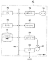
図1は本発明に係るカルテ作成装置を含む院内総合LANシステムの構成の実施の形態を示すシステム図であり、特に歯科用の院内総合LANシステムに関して示している。
[Configuration of in-hospital comprehensive LAN system including medical chart creation device]
FIG. 1 is a system diagram showing an embodiment of a configuration of an in-hospital comprehensive LAN system including a medical chart preparation apparatus according to the present invention, and particularly shows a dental in-hospital integrated LAN system.
同図に示すように、このシステムは、主として受付に設置されたカルテ管理サーバ10と、レントゲン室に設けられた歯牙のレントゲン撮影を行うレントゲン撮影装置20及び歯列のパノラマレントゲン撮影を行うレントゲン撮影装置22と、これらのレントゲン撮影装置20、22からデジタルレントゲン画像を取り込んで管理する画像管理サーバ30と、診療室の歯科用チェアーユニットに設置されたドクター端末40、42、44と、カウンセリング室(院長室)に設置された表示端末50とがLAN60にて接続されて構成されている。
As shown in the figure, this system mainly includes a
また、図示は省略したが、上記システムに口腔内写真を撮影するCCDカメラかつ/または患者の顔やあごの外形の画像を撮影するデジタルカメラを適宜追加してLAN60に接続してもよい。
Although not shown, a CCD camera that captures intraoral photographs and / or a digital camera that captures the image of the patient's face and jaws may be appropriately added to the system and connected to the
尚、ドクター端末40は、歯科用チェアーユニットのアームに取り付けられた液晶モニタを有し、ペンにてカルテ入力が可能なパーソナルコンピュータ(PC)であり、ドクター端末42はノート型PCであり、ドクター端末44はデスクトップ型PCである。
The
カルテ管理サーバ10は、主にスタッフによって使用されるもので、データベース・サーバとしての機能を有し、図2に示すようにデータベース12により各患者ごとのカルテへの記述内容(処置データ等)が保存される処置ファイルを管理する処置テーブルの他、後述するアイコンライン画像管理テーブル、ドクターメモファイル、摘要マスタ、部位ブロックテーブル等を患者識別情報(患者コード)に関連づけて管理している。
The medical
画像管理サーバ30は、画像データベース・サーバとしての機能を有し、図2に示すように画像データベース32により各患者ごとのデジタルレントゲン画像を患者コードに関連づけて管理している。即ち、レントゲン撮影装置20、22から取得したデジタルレントゲン画像の画像ファイルは、患者コード、撮影日などの付属情報が付加され、画像格納フォルダ内の患者コードに対応する患者フォルダに格納される。
The
ドクター端末40、42、44は、ドクターが診療室にてカルテ入力等を行うために使用され、表示端末50は、院長又は担当ドクターがカウンセリング室にて患者に対して処置や治療に必要な情報を提供する際に使用される。
The doctor terminals 40, 42, and 44 are used by the doctor for inputting medical records in the clinic, and the
上記カルテ管理サーバ10及び画像管理サーバ30で管理されている処置データ、デジタルレントゲン画像等の情報は、カルテ管理サーバ10、画像管理サーバ30、ドクター端末40、42、44、表示端末50の間でLAN60を通じて共有できるようになっている。
Information such as treatment data and digital X-ray images managed by the medical
次に、上記カルテ管理サーバ10、画像管理サーバ30、ドクター端末40、42、44及び表示端末50のハードウエア構成について説明する。尚、これらのハードウエア構成はほぼ同様のため、以下、ドクター端末40のハードウエア構成について説明する。
Next, the hardware configuration of the medical
図3に示すようにドクター端末40は、主として各構成要素の動作を制御する中央処理装置(CPU)70と、装置の制御プログラムが格納されたり、プログラム実行時の作業領域となる主メモリ72と、パソコンのオペレーティングシステム(OS)、本発明に係るカルテ作成プログラム、デジタルレントゲン画像、デジタルカメラで撮影された口腔画像などを閲覧するためのビューワソフト、各種のアプリケーションソフト等が格納されるハードディスク装置74、表示用データを一時記憶する表示メモリ76と、この表示メモリ76からの画像データ、文字データ等により画像や文字等を表示するCRTモニタや液晶モニタ等のモニタ装置78と、キーボード80と、位置入力装置としてのマウス82と、マウス82の状態を検出してモニタ装置78上のマウスポインタの位置やマウス82の状態等の信号をCPU70に出力するマウスコントローラ84と、LAN60を介して画像やカルテへの記載に必要な情報を送受信する通信インターフェース86と、上記各構成要素を接続するバス88とから構成されている。
As shown in FIG. 3, the
尚、上記構成のうちのハードディスク装置74に格納されるカルテ作成プログラムを除いて周知のものであるため、各構成要素の詳細な説明については省略する。
In addition, since it is a well-known thing except the chart preparation program stored in the hard-
[カルテ作成プログラム]
次に、本発明に係るカルテ作成プログラムの概略について説明する。
[Chart creation program]
Next, an outline of the chart creation program according to the present invention will be described.
このカルテ作成プログラムは、紙カルテと同じカルテ入力画面をモニタ装置に表示させ、カルテ入力後にカルテ印刷を実行させると、紙ベースの正規のカルテをプリント出力させる機能を有し、特に、以下の5つの特徴を有している。 This chart creation program has a function to display the same chart input screen as the paper chart on the monitor device, and when a chart printing is executed after the chart input, a paper-based regular chart is printed out. It has two features.
(1)アイコンライン
カルテに記載不要項目をカルテ上のアイコンライン(詳しくは後述する)上にアイコンで表示し、アイコンで表現された内容は紙カルテには印刷しない。また、デジタルレントゲン画像と療法・処置とのリンクをアイコンで表示する。
(1) Icon Line Items that are not required to be described in the medical chart are displayed as icons on an icon line on the medical chart (details will be described later), and the contents expressed by the icons are not printed on the paper medical chart. In addition, a link between the digital X-ray image and the therapy / treatment is displayed as an icon.
アイコンラインに表示されるアイコンには、以下の5つのアイコンがある
(a)画像アイコン
アイコンをクリックすることで撮影したレントゲン画像口腔内写真又は患者の外形の画像 (以下「 デジタルレントゲン画像等」という)を表示する。
The icons displayed in the icon line include the following five icons:
(a) Image icon
Clicking on the icon displays an X-ray image taken inside the mouth or an image of the patient's outline (hereinafter referred to as “digital X-ray image etc.”).
(b)病名アイコン
レセプト請求のために必要な病名をアイコンで表示する。
(b) Disease name icon The name of the disease required for receipt request is displayed as an icon.
(c)自費アイコン
保険診療分とは別記載となっている自費診療分の情報をアイコンにて表示する。自費アイコンをクリックすることで自費診療分の情報を確認することができる。
(c) Self-funded icons Information on self-funded medical treatments, which is described separately from insurance medical treatments, is displayed as icons. By clicking on the self-payment icon, information on the self-paid medical treatment can be confirmed.
(d)摘要アイコン
カルテには記載不要だがレセプトには必須の摘要をアイコンで表示する。摘要アイコンをクリックすることで摘要を確認することができる。
(d) Summary icon A description that is not required to be written in the medical chart but is required for the receipt is displayed as an icon. Click on the summary icon to check the summary.
(e)メモアイコン
カルテには記載しないドクターメモをアイコンにて表示する。メモアイコンをクリックすることでメモを確認することができる。
(e) Memo icon The doctor memo which is not described in the medical chart is displayed with an icon. You can check the memo by clicking the memo icon.
(2)部位と該当デジタルレントゲン画像等のリンク
口腔即時表示エリア内の該当の部位をクリックすることで、その部位に対応したデジタルレントゲン画像等を表示する。
(2) Link between site and corresponding digital X-ray image, etc. Clicking on the corresponding site in the immediate oral cavity display area displays a digital X-ray image or the like corresponding to that site.
療法・処置に伴うレントゲン画像を部位ごとに表示し、部位の経過が確認できる。レントゲン画像等を見ながらカルテ入力が可能となる。 The X-ray image associated with therapy / treatment is displayed for each part, and the progress of the part can be confirmed. Medical chart input is possible while viewing X-ray images.
(3)該当患者のパノラマ画像表示
口腔即時表示画面内の画像ボタンをクリックすることで、その患者のパノラマ画像を表示する。パノラマ画像を見ながらカルテ入力が可能となる。撮影したパノラマ画像を見ることで欠損部位、残根等の確認ができ部位の入力ミスを防ぐことができる。
(3) Display panoramic image of the patient Clicking the image button in the immediate oral cavity display screen displays the panoramic image of the patient. Medical chart input is possible while viewing panoramic images. By looking at the captured panoramic image, it is possible to confirm a missing part, a residual root, and the like, and to prevent an input error of the part.
(4)カルテ画面の縮小/拡大表示
カルテのサイズを小画面,中画面、大画面の3段階で変更可能にする。
(4) Reduction / enlargement display of chart screen The chart size can be changed in three stages: small screen, medium screen and large screen.
(5)2つの入力方式
ドクターが入力するカルテ入力方式と、受付窓口でスタッフが入力する診療入力方式(レセプト請求および会計のための入力)との2つの入力方式を搭載している。端末毎にドクターの入力端末、スタッフの入力端末で分けることができる。また、1端末で2つの入力方式の画面を切り替えて使用することも可能である。
(5) Two input methods There are two input methods: a chart input method input by a doctor and a medical input method (input for receipt request and accounting) input by a staff at the reception desk. Each terminal can be divided into a doctor input terminal and a staff input terminal. It is also possible to switch between two input method screens on one terminal.
[カルテ入力画面]
図4はカルテ入力画面の実施の形態を示す図である。
[Chart input screen]
FIG. 4 is a diagram showing an embodiment of a chart input screen.
図4に示すようにカルテ入力画面は、タイトル・バー100と、カルテ表示エリア110と、ボタンエリア120と、患者情報エリア130と、ファンクション・キーエリア132を有している。また、図4に示すカルテ入力画面には、別ウインドウで口腔即時表示画面140が表示されている。
As shown in FIG. 4, the chart input screen has a
タイトル・バー100には、「窓口業務: 患者コード 患者名 (バージョン) 」例)窓口業務:0000000001 日立 太郎(V13-01/03) が表示される。
In the
カルテ表示エリア110には、日付欄111、部位欄112、アイコンライン113、療法・処置欄114、点数欄115、負担金額欄116が設けられている。このカルテ表示エリア110のカルテ表示は、アイコンライン113を除いて歯科の2号用紙と同じフォーマットになっている。ここで、アイコンライン113とは、カルテの各行ごとに設けられたアイコンを貼り付けるための領域であって、カルテの上下方向に連続している一列の領域をいう。
In the
このカルテ入力画面上で患者コードを入力すると、カルテ管理サーバ10のデータベース12から該当患者の処置ファイル等を読み出し、カルテ表示エリア110等にカルテの内容が表示される。
When the patient code is input on the chart input screen, the treatment file of the patient is read from the
ボタンエリア120には、カルテのページを前ページ、次ページに移動させる「↑」「↓」ボタン、「戻る」ボタン、「添付領域指定」ボタン、「誘導」ボタン、「算定可能絞込」ボタン、「通常画面」ボタン、「チェック表示」ボタン、「再編成」ボタン、「メモ送信」ボタン、「口腔即時表示」ボタン、「取消」ボタン、「確定」ボタン、「拡大」ボタン、「縮小」ボタン、「処置担当表示」チェックボックス、「レセプト」ボタン、「カルテ」ボタン、及び「カルテ印刷」ボタンの各種のソフトボタンが縦に配列されている。
In the
患者情報エリア130には、選択患者「患者コード/患者名/年齢」、保険情報「主保険・福祉」、担当医、初診日、最終日の情報が表示される。
In the
ファンクション・キーエリア132には、キーボードのファンクション・キー(F1〜F12)に対応するボタンが表示されている。即ち、「取消」キー(F) 、「切替」キー(F2)134、「対象部位」キー(F3)、「選択」キー(F4)、「追加」キー(F5)、「変更」キー(F6)、「削除」キー(F7)、…、「確定」キー(F12) が表示される。
In the
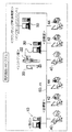
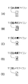
[アイコンライン]
次に、上記カルテ入力画面のアイコンライン113に、図5(A)乃至(D)に示す画像アイコン113A、病名アイコン113B、自費アイコン113C、摘要アイコン113D、及びメモアイコン113Eを登録する場合について説明する。
[Icon line]
Next, the case where the
〈画像アイコン〉
上記カルテ入力画面において、デジタルレントゲン画像等のデジタル画像をアイコン化し、アイコンライン113の該当する行に貼り付ける場合について説明する。
<Image icon>
A case will be described in which a digital image such as a digital X-ray image is converted into an icon on the medical record input screen and pasted on a corresponding line of the
図6(A)に示すように、まず画像アイコン113Aを貼り付けるアイコンライン113の該当する行をカーソルを移動させ、マウスの右ボタンを押下すると、図6(B)に示すようにポップアップ画面117が表示される。このポップアップ画面117には、「レセプト摘要表示画面」、「メモ表示画面」、「自費表示画面」、「画像表示画面」、及び「閉じる」のメニューが表示されている。
As shown in FIG. 6 (A), when the cursor is moved to the corresponding line of the
ここで、「画面表示画面」を選択すると、ビューワソフトが起動し、現在開いているカルテの患者コードに基づいて画像管理サーバ30の画像データベース32から該当患者のデジタルレントゲン画像等が読み出され、その画像の一覧がカルテ入力画面上の別ウインドウの画像表示画面150が表示される。
Here, when “screen display screen” is selected, the viewer software is activated, and the digital X-ray image of the patient is read from the
図6(C)に示すように、画像表示画面150に表示された画像の一覧から所望の画像をアイコンライン113の該当する行にドラッグ&ドロップすることにより、その画像とリンクした画像アイコン113Aが貼り付けられる。尚、マウスによるドラッグ&ドロップの操作に限らず、所望の画像の選択と登録実行の指示入力により画像アイコン113Aをアイコンライン113の該当する行に貼り付けることもできる。また、複数の画像の選択も可能である。
As shown in FIG. 6C, by dragging and dropping a desired image from the list of images displayed on the
この画像アイコン113Aの貼り付けの操作により、カルテ管理サーバ10は、カルテ入力画面上の画像アイコン113Aとリンクさせて患者の画像の画像ファイル名等をアイコンライン画像管理テーブルに登録する(図2参照)。
By the pasting operation of the
上記のようにして画像アイコン113Aをアイコンライン113に貼り付けておくと、その後、その画像アイコン113Aを貼り付けられた日のデジタルレントゲン画像等がどのような画像かを確認したい場合に、直ちに確認することができる。
If the
即ち、図7(A)に示すように、確認したい日の画像アイコン113Aをクリックすると、ビューワソフトが起動し、また、その画像アイコン113Aにリンクした患者の画像ファイル名がカルテ管理サーバ10のアイコンライン画像管理テーブルから読み出される。そして、患者コード、画像ファイル名を基に画像管理サーバ30の画像データベース32から該当患者のデジタルレントゲン画像等が読み出され、図7(B)に示すように画像表示画面150に表示される。
That is, as shown in FIG. 7A, when the
〈病名アイコン〉
病名をアイコン化し、アイコンライン113の該当する行に貼り付ける場合について説明する。
<Disease name icon>
A case where the disease name is converted into an icon and pasted on the corresponding line of the
病名は部位と関連しているため、部位入力画面にて同時に病名の入力ができるようになっている。 Since the disease name is related to the region, the disease name can be input simultaneously on the region input screen.
即ち、カルテ表示エリア110の部位欄112をクリックすると、図8(A)に示すように部位入力画面151が起動する。この部位入力欄151は、部位入力欄151Aと病名入力欄151Bとを有している。この病名入力欄151上で病名を入力すると、その病名はアイコン化され、図8(B)に示すように部位欄112の隣のアイコンライン113の行に病名アイコン113Bが貼り付けられる。
That is, when the
この病名アイコン113Bの貼り付けの操作により、カルテ管理サーバ10は、カルテ入力画面上の病名アイコン113Bをリンクさせて病名の情報を部位ブロックテーブルに部位の情報とともに登録する。
By pasting the
図9(A)に示すように、上記のようにして登録された病名アイコン113Bをクリックすると、図9(B)に示すように病名入力欄151Bが表示され、ここに病名が表示される。
As shown in FIG. 9A, when the
尚、療法・処置欄114に病名を記入すると、紙カルテ(2号用紙)に病名が印刷されてしまうが、2号用紙には病名を記入しないことになっている。上記のように病名をアイコン化することで、病名を印刷しないようにすることができ、その一方、アイコン化された病名の情報をレセプトに利用することができる。
If a disease name is entered in the therapy /
〈自費アイコン〉
自費診療分の情報をアイコン化し、アイコンライン113の該当する行に貼り付ける場合について説明する。
<Self-cost icon>
A case will be described in which the information for the self-paid medical treatment is converted into an icon and pasted on the corresponding line of the
図10(A)に示すように、まず自費アイコンを貼り付けるアイコンライン113の該当する行をカーソルを移動させ、マウスの右ボタンを押下すると、図10(B)に示すようにポップアップ画面117が表示される。このポップアップ画面117上で、「自費表示画面」を選択すると、図10(C)に示すようにカルテ入力画面上に別ウインドウの自費表示画面152が表示される。
As shown in FIG. 10A, when the cursor is moved to the corresponding line of the
この自費表示画面152上の自費欄に必要事項(例えば、上顎金属床、下顎金属床等)を記入し、自費表示画面152の「確定」ボタン152Aを押下すると、自費表示画面152が閉じ、また、自費診療分の情報は、自費アイコン113Cとしてアイコンライン113の該当する行に貼り付けられる。
If necessary items (for example, upper metal floor, lower jaw metal floor, etc.) are entered in the own expense column on the own
この自費アイコン113Cの貼り付けの操作により、カルテ管理サーバ10は、カルテ入力画面上の自費アイコン113Cとリンクさせて自費診療分の情報を自費マスタに登録する。
By the operation of pasting the self-
図11(A)に示すように、上記のようにして登録された自費アイコン113Cをクリックすると、図11(B)に示すように自費表示画面152が表示され、ここに自費診療分の情報が表示される。
As shown in FIG. 11 (A), when the self-
尚、自費診療分は、保険診療分のカルテとは別に記載しなければならないが、上記のようにアイコン化することで、自費診療分を紙カルテに印刷しないようにすることができる。 In addition, although the self-paid medical treatment must be described separately from the medical chart for the insurance medical care, it is possible to prevent the self-paid medical care from being printed on the paper medical chart by making it an icon as described above.
〈摘要アイコン〉
カルテには記載不要だが、レセプトには必須の摘要の情報をアイコン化し、アイコンライン113の該当する行に貼り付ける場合について説明する。
<Summary icon>
A description will be given of a case where the description information which is not required to be described in the medical chart but is essential for the receipt is converted into an icon and pasted on the corresponding line of the
図12(A)に示すように、まず摘要アイコンを貼り付けるアイコンライン113の該当する行をカーソルを移動させ、マウスの右ボタンを押下すると、図12(B)に示すようにポップアップ画面117が表示される。このポップアップ画面117上で、「レセプト摘要表示画面」を選択すると、図12(C)に示すようにカルテ入力画面上に別ウインドウのレセプト摘要表示画面153が表示される。
As shown in FIG. 12A, when the cursor is moved to the corresponding line of the
このレセプト摘要表示画面153上の摘要欄に必要事項(例えば、一日二度来院等)を記入し、レセプト摘要表示画面153の「確定」ボタン153Aを押下すると、レセプト摘要表示画面153が閉じ、また、摘要の情報は、摘要アイコン113Dとしてアイコンライン113の該当する行に貼り付けられる。
When a required item (for example, twice a day visit) is entered in the summary column on the receipt
この摘要アイコン113Dの貼り付けの操作により、カルテ管理サーバ10は、カルテ入力画面上の摘要アイコン113Dとリンクさせて摘要の情報を摘要マスタに登録する。
By the pasting operation of the
図13(A)に示すように、上記のようにして登録された摘要アイコン113Dをクリックすると、図13(B)に示すようにレセプト摘要表示画面153が表示され、ここに摘要の情報が表示される。
As shown in FIG. 13 (A), when the
尚、摘要は、カルテには記載不要だが、レセプト請求には必要であり、レセプトの作成に利用することができる。 The summary does not need to be described in the medical chart, but is necessary for claim receipt, and can be used to create a receipt.
〈メモアイコン〉
カルテには記載しないドクターメモをアイコン化し、アイコンライン113の該当する行に貼り付ける場合について説明する。
<Memo icon>
A case will be described in which a doctor memo not described in the medical chart is converted into an icon and pasted on a corresponding line of the
図14(A)に示すように、まずメモアイコンを貼り付けるアイコンライン113の該当する行をカーソルを移動させ、マウスの右ボタンを押下すると、図14(B)に示すようにポップアップ画面117が表示される。このポップアップ画面117上で、「メモ表示画面」を選択すると、図14(C)に示すようにカルテ入力画面上に別ウインドウのメモ表示画面154が表示される。
As shown in FIG. 14A, when the cursor is moved to the corresponding line of the
このメモ表示画面154上のデータ入力欄にドクターメモ(コメント)を記入して確定させると、メモ表示画面154が閉じ、また、ドクターメモの情報は、メモアイコン113Eとしてアイコンライン113の該当する行に貼り付けられる。
When a doctor memo (comment) is entered and confirmed in the data input field on the
このメモアイコン113Eの貼り付けの操作により、カルテ管理サーバ10は、カルテ入力画面上のメモアイコン113Eとリンクさせてドクターメモの情報をドクターメモファイルに登録する。
By the operation of pasting the
図15(A)に示すように、上記のようにして登録されたメモアイコン113Eをクリックすると、図15(B)に示すようにメモ表示画面154が表示され、ここにドクターメモの情報が表示される。
As shown in FIG. 15A, when the
尚、この実施の形態では、アイコンライン113の1行の欄に1つのアイコンを貼り付ける場合について説明したが、1行の欄に種類の異なる複数のアイコンを貼り付けることができる。また、アイコンライン113に登録されたアイコンは、アイコンライン113の任意の行に移動させることもできる。
In this embodiment, the case where one icon is pasted to the column of one line of the
[部位と該当デジタルレントゲン画像等のリンク]
まず、カルテ入力画面に別ウインドウで表示される口腔即時表示画面140について説明する。
[Link between site and corresponding digital X-ray image]
First, the oral cavity
図4に示すように口腔即時表示画面140は、タイトル・バー141と、「画像」ボタン142と、「 凡例」ボタン143と、「乳歯/永久歯」ボタン144と、口腔即時表示エリア145とを有している。尚、タイトル・バー141には、「口腔即時表示」が表示されており、「最小化」ボタン、「元のサイズに戻す」ボタン、「閉じる」ボタンが設けられている。また、口腔即時表示画面140が閉じられているときに、カルテ入力画面のボタンエリア120中の「口腔表示」ボタンを押下すると、カルテ入力画面上に口腔即時表示画面140を表示させることができる。
As shown in FIG. 4, the immediate oral
「画像」ボタン142は、該当患者のパノラマ画像を表示させるためのボタンである。このパノラマ画像表示の詳細については後述する。また、「 凡例」ボタン143は、ヘルプ画面を表示させるためのボタンであり、「乳歯/永久歯」ボタン144は、口腔即時表示エリア145の歯列のイラスト表示を永久歯の表示から乳歯の表示に切り替え、又は乳歯の表示から永久歯の表示に切り替えるためのボタンである。尚、永久歯表示中には「乳歯」と表示され、乳歯表示中には「永久歯」と表示される。
The “image”
口腔即時表示エリア145には、前述したように歯列のイラスト(部位)が表示されており、イラストで示された部位は、後述するように対応する歯牙のレントゲン画像を表示させるためのアイコンとして機能する。また、レントゲン画像が存在する部位は、治療歴のない部位とは色分けされ、または濃淡が付けられており、両者を区別できるようになっている。
In the oral cavity
次に、口腔即時表示エリア145に示された所望の部位に対応するレントゲン画像を表示させる機能について説明する。
Next, a function of displaying an X-ray image corresponding to a desired site shown in the oral cavity
図16(A)に示すように、口腔即時表示エリア145に示された所望の部位にカーソルを移動させてクリックする。これにより、ビューワソフトが起動し、また、クリックされた指定された部位の情報を基にその部位にリンクした該当患者の同部位のレントゲン画像を画像管理サーバ30の画像データベース32から取得し、図16(B)に示すように画像表示画面150に表示する。
As shown in FIG. 16A, the cursor is moved to a desired site shown in the oral cavity
尚、画像管理サーバ30の画像データベース32に登録された画像ファイルは、画像データベース32への登録時等に入力された患者コード、部位、撮影日、画像の属性などの情報に基づいて検索できるようになっている。
The image file registered in the
図16(B)に示した実施の形態では、該当部位の1つのレントゲン画像が画像表示画面150に表示されているが、該当部位のレントゲン画像が複数存在する場合には、複数のレントゲン画像が撮影日順に画像表示画面150に表示される。
In the embodiment shown in FIG. 16B, one X-ray image of the corresponding part is displayed on the
これにより、処理に伴うレントゲン画像を部位ごとに表示することができ、部位の経過も容易に確認することができる。 Thereby, the X-ray image accompanying a process can be displayed for every site | part, and progress of a site | part can also be confirmed easily.
[該当患者のパノラマ画等表示]
次に、レントゲン撮影装置22によって撮影された歯列のパノラマ画像を表示させる機能について説明する。
[Display panorama image of the patient]
Next, a function of displaying a panoramic image of a dentition photographed by the
図17(A)に示すように、口腔即時表示画面140内の「画像」ボタン142を押下すると、ビューワソフトが起動し、また、「画像」ボタン142の押下に対応して「パノラマ」の画像の属性を有する、該当患者の歯列を示すパノラマ画像を画像管理サーバ30の画像データベース32から取得する。そして、図17(B)に示すように、画像データベース32から取得したパノラマ画像を画像表示画面150に表示する。
As shown in FIG. 17A, when the “image”
このようにワンクリックで、患者のパノラマ画像を直ちに検索して表示することができ、パノラマ画像を見ながらカルテ入力が可能になる。また、パノラマ画像を見ながらカルテ入力が可能であり、撮影したパノラマ画像を見ることで欠損部位、残根等の確認ができ部位の入力ミスを防ぐことができる。 In this way, with one click, a panoramic image of a patient can be retrieved and displayed immediately, and a chart can be input while viewing the panoramic image. In addition, it is possible to input a medical chart while viewing a panoramic image, and by confirming a shot panoramic image, it is possible to confirm a defective part, a residual root, and the like, and to prevent an input error of the part.
また、ここではパノラマ画像を例に挙げて説明したが、CCDカメラで撮影した口腔内写真又はデジタルカメラで撮影した患者の外形の画像としてもよい。これら各画像を治療前後に撮影しておけば患者のインフォームドコンセントに活用できる。 In addition, although a panoramic image has been described as an example here, an intraoral photograph taken with a CCD camera or an image of a patient's outline taken with a digital camera may be used. If these images are taken before and after treatment, they can be used for informed consent of patients.
[カルテ画面の縮小/拡大表示]
図18乃至図20はそれぞれ小画面、中画面(標準画面)及び大画面のカルテ入力画面を示している。
[Reduced / enlarged display of chart screen]
18 to 20 show a chart input screen of a small screen, a medium screen (standard screen), and a large screen, respectively.
歯科の紙カルテには、B5とA4の2種類のサイズがあり、B5の2号用紙は1ページが24行で構成され、A4の2号用紙は1ページが32行で構成されている。同じ院内ではB5とA4のうちのいずれか一方のサイズのカルテを使用するため、カルテ入力画面内のカルテ表示エリア110に表示される2号用紙をそのまま入力画面化したカルテは、その院内で使用する紙カルテと同じサイズのものにカスタマイズされている。尚、この実施の形態では、B5の紙カルテに適合するようにカスタマイズされている。
There are two types of dental paper charts, B5 and A4. B5 No. 2 paper consists of 24 lines per page, and A4 No. 2 paper consists of 32 lines per page. In the same hospital, a chart of either B5 or A4 size is used, so the chart that has been used as the input screen for No. 2 paper displayed in the
図18乃至図20に示すように、拡大/縮小される画面は、カルテ表示エリア110だけであり、カルテ入力画面を構成する他のタイトル・バー100、ボタンエリア120、及び患者情報エリア130のサイズは変動しないようになっている。
As shown in FIGS. 18 to 20, the screen to be enlarged / reduced is only the
また、ボタンエリア120及び患者情報エリア130は、カルテ表示エリア110が拡大するにしたがって画面左側に移動し、図20に示すように大画面時には患者情報エリア130はカルテ入力画面から削除される。
Further, the
更に、大画面時に削除された患者情報エリア130に表示されていた患者情報のうちの一部(この実施の形態では、年齢と保険情報)は、図20に示すようにタイトル・バー100にて表示される。尚、タイトル・バー100にはもともと患者情報のうちの患者コードと患者名が表示されているが、大画面時に患者情報の一部が追加されることになる。
Furthermore, a part of the patient information (in this embodiment, age and insurance information) displayed in the
また、小画面、中画面及び大画面時の患者情報エリア130の拡大縮小比率は、80/90、100/100及び120/90であり、特に小画面時にはカルテ1ページ分が納まるようになっている。
The enlargement / reduction ratios of the
上記小画面、中画面及び大画面の3段階の変更は、ボタンエリア120内の「拡大」ボタン121、「縮小」ボタン122をクリックすることによって行うことができる。
The change in three stages of the small screen, the medium screen, and the large screen can be performed by clicking the “enlarge”
図21は上記「拡大」ボタン121、「縮小」ボタン122の操作によるカルテ画面(小、中、大画面)の画面遷移を示す図である。
FIG. 21 is a diagram showing screen transition of the chart screen (small, medium, large screen) by the operation of the “enlarge”
同図に示すように、中画面(標準画面)時に「拡大」ボタン121、又は「縮小」ボタン122をクリックすると、中画面は大画面、又は小画面に遷移する。
As shown in the figure, when the “enlarge”
また、大画面時には「縮小」ボタン122のみクリックできるようになっており、「縮小」ボタン122をクリックすると中画面に遷移し、一方、小画面時には「拡大」ボタン121のみクリックできるようになっており、「拡大」ボタン121をクリックすると中画面に遷移する。
Further, only the “reduction”
[2つの入力方式]
図22は現行の診療入力画面を示す図である。
[Two input methods]
FIG. 22 is a diagram showing a current medical care input screen.
この診療入力画面では、スタッフによりレセプト請求、会計のための診療情報等が入力される。また、診療入力画面では、カルテに印字しない項目についても、テキストデータがそのまま表示される。即ち、カルテ入力画面で表示されているアイコンの「病名」及び「摘要」については、診療入力画面では文字情報として表示させる。 On this medical care input screen, the staff inputs medical information for billing and accounting. In addition, on the diagnosis input screen, text data is displayed as it is for items that are not printed on the chart. That is, the “disease name” and “explanation” of the icons displayed on the chart input screen are displayed as character information on the medical care input screen.
また、診療入力画面のファンクション・キーエリア160には、カルテ入力画面と同様にキーボードのファンクション・キー(F1〜F12)に対応するボタンが表示される。即ち、「取消」キー(F1)、「切替」キー(F2)162、「対象部位」キー(F3)、「選択」キー(F4)、「追加」キー(F5)、「変更」キー(F6)、「削除」キー(F7)、…、「患者終了」キー(F12) が表示される。
In the
そして、診療入力画面の「切替」キー162をクリックすると、図4に示したカルテ入力画面に切り替わり、同様にカルテ入力画面のファンクション・キーエリア135の「切替」キー134をクリックすると、診療入力画面に切り替わる。
When the “switch”
これにより、1つの端末でカルテ入力方式と診療入力方式の2つの方式を切り替えて使用することができる。 Thereby, it is possible to switch between the two methods of the chart input method and the medical care input method with one terminal.
尚、プログラム起動時にいずれの入力画面を表示させるかは、そのプログラム起動時の設定 (デフォルト)により、適宜決めることができる。受付窓口等でスタッフが使用する端末は、デフォルトで診療入力画面に設定し、診察室でドクターが使用する端末は、デフォルトでカルテ入力画面に設定するのが好ましい。 Note that which input screen is displayed when the program is started can be appropriately determined by the setting (default) at the time of starting the program. It is preferable that a terminal used by a staff member at a reception desk or the like is set as a default on the medical input screen, and a terminal used by a doctor in the examination room is set as a default on the medical record input screen.
また、この実施の形態では、カルテ管理サーバ10が患者ごとのカルテへの記述内容等を管理し、画像管理サーバ30が患者ごとのデジタルレントゲン画像等を管理するようにしたが、いずれか一方が両者の管理機能を具備するようにしてもよい。
In this embodiment, the medical
また、この実施の形態では、患者コードの入力をカルテ入力画面で入力したが、患者情報入力画面を別途作成し、その作成された患者情報入力画面に患者氏名、性別、生年月日などを入力してもよい。 In this embodiment, the patient code is input on the chart input screen. However, a patient information input screen is created separately, and the patient name, gender, date of birth, etc. are input on the created patient information input screen. May be.
10…カルテ管理サーバ、12…データベース、20、22…レントゲン撮影装置、30…画像管理サーバ、32…画像データベース、40、42、44…ドクター端末、50…表示端末、60…LAN、100…タイトル・バー、110…カルテ表示エリア、111…日付欄、112…部位欄、113…アイコンライン、113A…画像アイコン、113B…病名アイコン、113C…自費アイコン、113D…摘要アイコン、113E…メモアイコン、114…療法・処置欄、115…点数欄、116…負担金額欄、117…ポップアップ画面、120…ボタンエリア、121…「拡大」ボタン、122…「縮小」ボタン、130…患者情報エリア、132、160…ファンクション・キーエリア、134、162…「切替」ボタン、140…口腔即時表示画面、142…「画像」ボタン、145…口腔即時表示エリア、150…画像表示画面、151…部位入力画面、152…自費表示画面、153…レセプト摘要表示画面、154…メモ表示画面
DESCRIPTION OF
Claims (6)
拡大ボタン及び縮小ボタンを含む複数のソフトボタンが表示されるボタンエリアと、患者に関連する情報が表示される患者情報エリアとを有するカルテ入力画面を表示手段に表示させる表示制御手段と、
前記拡大ボタン又は縮小ボタンの操作に基づいて前記カルテ表示エリアを拡大又は縮小させる倍率変更手段と、
前記カルテ表示エリアの拡大又は縮小に伴って前記ボタンエリア及び患者情報エリアのうちの少なくとも一方の前記カルテ入力画面内でのレイアウトを変更させるレイアウト変更手段と、
を備えたことを特徴とするカルテ作成装置。 A chart display area in which a digitalized chart (hereinafter referred to as “karte”) in a predetermined format is displayed, and a chart display area having a horizontal width capable of displaying one entire line of the chart;
Display control means for displaying on the display means a chart input screen having a button area in which a plurality of soft buttons including an enlargement button and a reduction button are displayed, and a patient information area in which information related to the patient is displayed;
Magnification changing means for enlarging or reducing the chart display area based on an operation of the enlargement button or reduction button;
Layout changing means for changing the layout in the chart input screen of at least one of the button area and the patient information area in accordance with the enlargement or reduction of the chart display area;
A medical chart creation device characterized by comprising:
前記拡大ボタン又は縮小ボタンの操作に基づいて前記カルテ表示エリアを拡大又は縮小させる倍率変更機能と、
前記カルテ表示エリアの拡大又は縮小に伴って前記ボタンエリア及び患者情報エリアのうちの少なくとも一方の前記カルテ入力画面内でのレイアウトを変更させるレイアウト変更機能と、
をコンピュータに実現させることを特徴とするカルテ作成プログラム。 Medical chart input having a medical chart display area for displaying a chart in a predetermined format, a button area for displaying a plurality of soft buttons including an enlargement button and a reduction button, and a patient information area for displaying information related to a patient A display control function for displaying a screen on a display means;
A magnification changing function for enlarging or reducing the chart display area based on an operation of the enlargement button or reduction button;
A layout changing function for changing the layout in the chart input screen of at least one of the button area and the patient information area in accordance with the enlargement or reduction of the chart display area;
A medical record creation program characterized by having a computer realize this.
Priority Applications (1)
| Application Number | Priority Date | Filing Date | Title |
|---|---|---|---|
| JP2004004414A JP4264729B2 (en) | 2004-01-09 | 2004-01-09 | Medical chart creation device and program |
Applications Claiming Priority (1)
| Application Number | Priority Date | Filing Date | Title |
|---|---|---|---|
| JP2004004414A JP4264729B2 (en) | 2004-01-09 | 2004-01-09 | Medical chart creation device and program |
Publications (3)
| Publication Number | Publication Date |
|---|---|
| JP2005196661A JP2005196661A (en) | 2005-07-21 |
| JP2005196661A5 JP2005196661A5 (en) | 2006-11-24 |
| JP4264729B2 true JP4264729B2 (en) | 2009-05-20 |
Family
ID=34819037
Family Applications (1)
| Application Number | Title | Priority Date | Filing Date |
|---|---|---|---|
| JP2004004414A Expired - Lifetime JP4264729B2 (en) | 2004-01-09 | 2004-01-09 | Medical chart creation device and program |
Country Status (1)
| Country | Link |
|---|---|
| JP (1) | JP4264729B2 (en) |
Families Citing this family (1)
| Publication number | Priority date | Publication date | Assignee | Title |
|---|---|---|---|---|
| US8579814B2 (en) | 2007-01-05 | 2013-11-12 | Idexx Laboratories, Inc. | Method and system for representation of current and historical medical data |
-
2004
- 2004-01-09 JP JP2004004414A patent/JP4264729B2/en not_active Expired - Lifetime
Also Published As
| Publication number | Publication date |
|---|---|
| JP2005196661A (en) | 2005-07-21 |
Similar Documents
| Publication | Publication Date | Title |
|---|---|---|
| JP6907253B2 (en) | Conference support system, conference support method and program | |
| JP5390805B2 (en) | OUTPUT DEVICE AND METHOD, PROGRAM, AND RECORDING MEDIUM | |
| JP5835381B2 (en) | Image processing apparatus and program | |
| JP2004305289A (en) | Medical system | |
| JP5958321B2 (en) | Medical information processing apparatus and program | |
| JP4992896B2 (en) | Medical imaging system | |
| JP4932204B2 (en) | Medical support system, medical support device, and medical support program | |
| JP2008090715A (en) | Medical information management system, medical information management device, and medical information management program | |
| JP4781019B2 (en) | Referral letter creation support device | |
| JP5935216B2 (en) | Medical information display device and medical information display program | |
| JP2013228800A (en) | Information processing apparatus, information processing method and program | |
| JP4460311B2 (en) | Medical chart creation device and program | |
| JP2007094515A (en) | Radiography reading report preparation device | |
| JP2007087285A (en) | Apparatus for creating diagnostic reading report and client terminal | |
| JPWO2008117634A1 (en) | Medical image display system | |
| JP5223916B2 (en) | Program and recording medium | |
| JP2005196662A (en) | Dental practice support device | |
| JP4264729B2 (en) | Medical chart creation device and program | |
| JP2013186651A (en) | Conference support apparatus, conference support method, and program | |
| JP2009211647A (en) | Medical image system, client terminal, and program | |
| JP5958320B2 (en) | Electronic medical record apparatus and program | |
| JP2005118074A (en) | Method and device for controlling inspection device | |
| US20110078632A1 (en) | Inspection information administering system, inspection information administering method and computer readable medium | |
| JP6794495B2 (en) | Shooting processing system, its control method and program | |
| JP2010200936A (en) | Medical image display, medical image display method, and program |
Legal Events
| Date | Code | Title | Description |
|---|---|---|---|
| A521 | Request for written amendment filed |
Free format text: JAPANESE INTERMEDIATE CODE: A523 Effective date: 20061004 |
|
| A621 | Written request for application examination |
Free format text: JAPANESE INTERMEDIATE CODE: A621 Effective date: 20061004 |
|
| A711 | Notification of change in applicant |
Free format text: JAPANESE INTERMEDIATE CODE: A711 Effective date: 20080723 |
|
| A977 | Report on retrieval |
Free format text: JAPANESE INTERMEDIATE CODE: A971007 Effective date: 20090116 |
|
| TRDD | Decision of grant or rejection written | ||
| A01 | Written decision to grant a patent or to grant a registration (utility model) |
Free format text: JAPANESE INTERMEDIATE CODE: A01 Effective date: 20090121 |
|
| A01 | Written decision to grant a patent or to grant a registration (utility model) |
Free format text: JAPANESE INTERMEDIATE CODE: A01 |
|
| A61 | First payment of annual fees (during grant procedure) |
Free format text: JAPANESE INTERMEDIATE CODE: A61 Effective date: 20090203 |
|
| R150 | Certificate of patent or registration of utility model |
Ref document number: 4264729 Country of ref document: JP Free format text: JAPANESE INTERMEDIATE CODE: R150 Free format text: JAPANESE INTERMEDIATE CODE: R150 |
|
| FPAY | Renewal fee payment (event date is renewal date of database) |
Free format text: PAYMENT UNTIL: 20120227 Year of fee payment: 3 |
|
| FPAY | Renewal fee payment (event date is renewal date of database) |
Free format text: PAYMENT UNTIL: 20130227 Year of fee payment: 4 |
|
| R250 | Receipt of annual fees |
Free format text: JAPANESE INTERMEDIATE CODE: R250 |
|
| FPAY | Renewal fee payment (event date is renewal date of database) |
Free format text: PAYMENT UNTIL: 20130227 Year of fee payment: 4 |
|
| FPAY | Renewal fee payment (event date is renewal date of database) |
Free format text: PAYMENT UNTIL: 20130227 Year of fee payment: 4 |
|
| FPAY | Renewal fee payment (event date is renewal date of database) |
Free format text: PAYMENT UNTIL: 20130227 Year of fee payment: 4 |
|
| FPAY | Renewal fee payment (event date is renewal date of database) |
Free format text: PAYMENT UNTIL: 20140227 Year of fee payment: 5 |
|
| S533 | Written request for registration of change of name |
Free format text: JAPANESE INTERMEDIATE CODE: R313533 |
|
| R350 | Written notification of registration of transfer |
Free format text: JAPANESE INTERMEDIATE CODE: R350 |
|
| RD02 | Notification of acceptance of power of attorney |
Free format text: JAPANESE INTERMEDIATE CODE: R3D02 |
|
| R250 | Receipt of annual fees |
Free format text: JAPANESE INTERMEDIATE CODE: R250 |
|
| R250 | Receipt of annual fees |
Free format text: JAPANESE INTERMEDIATE CODE: R250 |
|
| R250 | Receipt of annual fees |
Free format text: JAPANESE INTERMEDIATE CODE: R250 |
|
| S533 | Written request for registration of change of name |
Free format text: JAPANESE INTERMEDIATE CODE: R313533 |
|
| R350 | Written notification of registration of transfer |
Free format text: JAPANESE INTERMEDIATE CODE: R350 |
|
| R250 | Receipt of annual fees |
Free format text: JAPANESE INTERMEDIATE CODE: R250 |
|
| R250 | Receipt of annual fees |
Free format text: JAPANESE INTERMEDIATE CODE: R250 |
|
| S111 | Request for change of ownership or part of ownership |
Free format text: JAPANESE INTERMEDIATE CODE: R313111 |
|
| EXPY | Cancellation because of completion of term | ||
| R350 | Written notification of registration of transfer |
Free format text: JAPANESE INTERMEDIATE CODE: R350 |