JP4262847B2 - Ceramic heater and glow plug including the same - Google Patents
Ceramic heater and glow plug including the same Download PDFInfo
- Publication number
- JP4262847B2 JP4262847B2 JP31153299A JP31153299A JP4262847B2 JP 4262847 B2 JP4262847 B2 JP 4262847B2 JP 31153299 A JP31153299 A JP 31153299A JP 31153299 A JP31153299 A JP 31153299A JP 4262847 B2 JP4262847 B2 JP 4262847B2
- Authority
- JP
- Japan
- Prior art keywords
- ceramic heater
- heating resistor
- conductive component
- glow plug
- raw material
- Prior art date
- Legal status (The legal status is an assumption and is not a legal conclusion. Google has not performed a legal analysis and makes no representation as to the accuracy of the status listed.)
- Expired - Fee Related
Links
Images

Landscapes
- Resistance Heating (AREA)
Description
【0001】
【発明の属する技術分野】
本発明はセラミックヒータ及びそれを備えるグロープラグに関する。更に詳しくは、本発明は、発熱抵抗体の形成に用いられるWC等の導電成分に含まれるFe分による窒化珪素原料等、セラミック原料の焼結性の低下が抑えられ、優れた抗折強度と耐久性とを併せ有するセラミックヒータ及びそれを備えるグロープラグに関する。本発明のセラミックヒータは、ディーゼルエンジンのグロープラグの加熱源の他、各種の用途において使用することができる。
【0002】
【従来の技術】
グロープラグ等に使用されるセラミックヒータとして、窒化珪素質焼結体に、WC等の導電成分を含む発熱抵抗体を埋設したものが知られている。このWC等は、超硬合金等の分野においては、一般に、Co、Fe、Ni、Mo、Cr等を用いて焼成される。この焼成は1350〜1550℃程度の比較的低温で行うことができる。しかし、得られる焼結体の使用最高温度も1000℃以下に限定され、1200℃前後、或いはそれ以上の温度域において用いられるグロープラグ等のヒータとして使用することはできない。
【0003】
そこで、発熱抵抗体に含まれる絶縁成分を形成するためのセラミック原料の焼成を、発熱抵抗体の耐熱性の低下が少ない焼結助剤を使用し、且つ緻密化が損なわれない範囲で可能な限り少量用いて行うことにより、使用最高温度の高いヒータとする方法が一般に実用化されている。しかし、WC等に含まれる不純物がセラミック原料の焼結性を低下させるため、焼結助剤を十分に減量することができず、これまでヒータの使用最高温度は1300℃が限界であった。また、この不純物による部分的な焼結不良により抗折強度及び耐久性のばらつきを生じ、品質が安定しないこともあった。
【0004】
この種のセラミックヒータはグロープラグの加熱源として有用である。通常、ディーゼルエンジンに使用されるグロープラグには、乗用車等であれば12V、大型トラック等であれば24Vの定格バッテリー電圧が直接印加されるが、近年、ワイヤーハーネスの軽量化のため、電流を抑える必要が生じ、バッテリー電圧を24Vを越えて高くしなければならなくなっている。しかし、このような高い電圧をグロープラグに印加した場合、セラミックヒータの基体を構成するセラミックのマイグレーションを起因とし、発熱抵抗体の粒界におけるイオン移動を生じ易くなる。そのため、発熱抵抗体の粒界成分が基体へと移動し、発熱抵抗体の組織が粗くなり、これが原因で、特に、24Vを越える高電圧を印加した場合は、断線し易くなる。
【0005】
【発明が解決しようとする課題】
本発明は、上記の従来の問題点を解決するものであり、WC等の導電成分の原料に含まれるFe分による窒化珪素原料等、セラミック原料の焼結性の低下が抑えられ、品質が安定しており、優れた抗折強度と耐久性とを併せ有するセラミックヒータ及びそれを備えるグロープラグを提供することを目的とする。
【0006】
【課題を解決するための手段】
本発明のセラミックヒータは、窒化珪素質焼結体からなる基体と、該基体に埋設される発熱抵抗体とを備えるセラミックヒータにおいて、該発熱抵抗体に含有されるFe量が0.0435重量%以下であり、上記発熱抵抗体は導電成分であるWCと窒化珪素質焼結体からなる絶縁成分とからなり、該導電成分に含有されるFe量が0.075重量%以下であることを特徴とする。
【0007】
また、この発熱抵抗体は導電成分と絶縁成分とからなり、導電成分に含有されるFe量が0.075重量%以下である。発熱抵抗体に含有されるFe量は、Fe分を積極的に含有させなければ、焼成後、導電成分となる原料に不純物として含まれているFe量と実質的に同量である。そして、発熱抵抗体における導電成分の量比が高い場合であっても、発熱抵抗体に含有されるFe量が0.0435重量%以下であれば、絶縁成分を形成する窒化珪素原料等のセラミック原料の焼結性の低下が十分に抑えられる。
【0008】
更に、不純物として含まれているFe量が少ないWCを導電成分原料として用いた場合は、導電成分に含有されるFe量を0.046重量%以下とすることができる。このように導電成分に含有されるFe量が少なければ、焼成後、絶縁成分となる窒化珪素原料等のセラミック原料の焼結性の低下を特に十分に抑えることができるため好ましい。尚、本発明において、Fe量はX線マイクロアナライザーにより定量することができる。
【0009】
上記「基体」は、通常、窒化珪素質焼結体からなる。この焼結体は、窒化珪素のみからなるものであってもよいし、窒化珪素を主成分とし、これに少量の窒化アルミニウム、アルミナ等が含有されるものであってもよい。また、サイアロンであってもよい。
【0010】
上記「発熱抵抗体」は導電成分と絶縁成分により構成される。
導電成分は、W、Ta、Nb、Ti、Mo、Zr、Hf、V、及びCrから選ばれる1種以上の金属元素の珪化物、炭化物又は窒化物等のうちの少なくとも1種が焼成され、形成される。また、絶縁成分は、通常、窒化珪素質焼結体からなる。導電成分は、特に、その熱膨張率が基体を構成する窒化珪素質焼結体、若しくは絶縁成分である窒化珪素質焼結体と大きな差がないものが好ましい。熱膨張率の差が小さい導電成分であれば、ヒータ使用時の基体及び発熱抵抗体における亀裂の発生が抑えられる。そのような導電成分としては、WC、MoSi2、TiN又はWSi2等が挙げられる。更に、この導電成分としては、その融点がセラミックヒータの使用温度を越え、耐熱性の高いものが好ましい。導電成分の融点が高ければ使用温度域におけるヒータの耐熱性も向上する。
【0011】
導電成分と絶縁成分との量比は特に限定されないが、発熱抵抗体を100体積部とした場合に、導電成分を15〜40体積部とすることができ、特に20〜30体積部とすることができる。
【0012】
本発明のセラミックヒータは、以下のようにして製造することができる。
導電成分の原料粉末として、W、Ti及びMo等の金属元素の珪化物、炭化物又は窒化物等からなる粉末を使用する。また、絶縁成分の原料粉末として窒化珪素原料粉末等のセラミック原料粉末及び焼結助剤粉末を用いる。この焼結助剤粉末としては、希土類酸化物粉末が多用されるが、MgO及びAl2O3−Y2O3等、一般に窒化珪素質焼結体の焼成において用いられる酸化物等の粉末を使用することもできる。これらの焼結助剤粉末は1種のみを使用してもよいが、2種以上を併用することが多い。尚、Er2O3等、焼結した場合の粒界が結晶相となる焼結助剤粉末を用いると耐熱性がより高くなるため好ましい。
【0013】
これら導電成分用原料粉末、セラミック原料粉末、及び焼結助剤粉末を所定の量比で混合し、混合粉末を調製する。この混合は、湿式等、通常の方法によって行うことができる。
導電成分用原料粉末、セラミック原料粉末及び焼結助剤粉末は、これらの合計量を100体積部とした場合に、導電成分用原料粉末を15〜40体積部、特に20〜30体積部、残部をセラミック原料粉末と焼結助剤粉末とで85〜60体積部、特に80〜70体積部とすることができる。
【0014】
このようにして調製した混合粉末に、適量のバインダー等を配合して混練した後、造粒し、これを用いて、射出成形等の方法により、焼成後、発熱抵抗体となる成形体とすることができる。また、この成形体の所定の位置にタングステン等の金属からなるリード線が取り付けられる。
【0015】
その後、この成形体を、基体用原料粉末に埋入する。その方法としては、基体用原料粉末を圧粉した半割型を2個用意し、これらの半割型の間の所定位置に成形体を載置した後、プレス成形する方法等が挙げられる。次いで、これらを一体に50〜120気圧程度に加圧することにより、基体の形状を有する粉末成形体に発熱抵抗体となる成形体が埋設されたセラミックヒータ成形体が得られる。このセラミックヒータ成形体を、黒鉛製等の加圧用ダイスに収納し、これを焼成炉に収容し、所定の温度で所要時間、ホットプレス焼成することにより、セラミックヒータを製造することができる。焼成温度及び焼成時間は特に限定されないが、焼成温度は1700〜1850℃、焼成時間は30〜180分、特に60〜120分とすることができる。
【0016】
本発明のセラミックヒータは品質が安定しており、優れた抗折強度と耐久性とを併せ有する。即ち、本発明のセラミックヒータでは、JIS R 1601に準じて測定した抗折強度が1000MPa以上であり、且つ1300℃における通電と通電の停止とを5000サイクル繰り返した場合に、断線を生ずることのないセラミックヒータとすることができる。更に、抗折強度が1250MPa以上であり、且つ1400℃における通電と通電の停止とを10000サイクル繰り返した場合に、断線を生ずることのないセラミックヒータとすることができる。
【0017】
本発明のセラミックヒータでは、その抗折強度は、1000〜1400MPaとすることができ、特に1100〜1400MPa、更には1200〜1400MPaとすることができる。また、抗折強度の最少値と平均値との差は、100MPa以下とすることができ、特に80MPa以下、更には50MPa以下とすることができる。更に、抗折強度の平均値と最小値との差の平均値に対する割合は、9%以下とすることができ、特に7%以下、更には5%以下とすることができる。
【0018】
また、本発明のセラミックヒータでは、1300℃における通電と通電の停止とを、5000サイクル以上、特に8000サイクル以上、更には10000サイクル繰り返しても、断線等を生ずることのない優れたセラミックヒータとすることができる。更に、特に、本発明のセラミックヒータでは、1400℃における通電と通電の停止とを5000サイクル以上、特に8000サイクル以上、更には10000サイクル繰り返しても、断線等を生ずることのないより優れた耐久性を有するセラミックヒータとすることができる。
【0019】
本発明では、前記のように、優れた抗折強度と耐久性とを併せ有するセラミックヒータとすることができ、抗折強度が1000〜1400MPaであり、且つ1300℃、特に1400℃における通電と通電の停止とを、5000サイクル以上繰り返しても、断線等を生ずることのない優れたセラミックヒータとすることができる。また、抗折強度が1100〜1400MPaであり、且つ1300℃、特に1400℃における通電と通電の停止とを、8000サイクル以上繰り返しても、断線等を生ずることのない優れたセラミックヒータとすることもできる。更に、抗折強度が1200〜1400MPaであり、1300℃、特に1400℃における通電と通電の停止とを、10000サイクル繰り返しても、断線等を生ずることのない優れたセラミックヒータとすることもできる。
【0020】
本発明のグロープラグは、本発明のセラミックヒータを備え、24V以上の電圧が印加されることを特徴とする。本発明のセラミックヒータでは、熱抵抗体の形成に用いる焼結助剤を減量することができ、粒界成分の移動を抑えることができる。そのため、このセラミックヒータを加熱源として備えるグロープラグでは、使用時、ヒータが断線等の問題を生ずることがなく、耐久性に優れる。尚、このグロープラグにおいて、印加される電圧は、人体の感電防止等の観点から50V以下、特に42V以下であることが好ましい。
【0021】
【発明の実施の形態】
以下、本発明のセラミックヒータを実施例により更に詳しく説明する。
(1)セラミックヒータの作製
85重量%の窒化珪素原料粉末に、焼結助剤として、10重量%のEr2O3粉末及び5重量%のSiO2粉末を配合して絶縁成分用原料とした。この絶縁成分用原料42重量%と導電成分用原料であるWC粉末(表1に記載のFe分を含有する。)58重量%とを、72時間湿式混合した後、乾燥し、混合粉末を得た。その後、この混合粉末とバインダーとを混練機に投入し、4時間混練した。次いで、得られた混練物を裁断してペレット状とし、これを射出成型機に投入してタングステン製のリード線が両端に嵌合されたU字状の発熱抵抗体となる成形体を得た。
【0022】
一方、83重量%の窒化珪素原料粉末に、焼結助剤として10重量%のEr2O3粉末、5重量%のSiO2粉末及び2重量%のMoSi2粉末を配合し、40時間湿式混合したものをスプレードライヤー法によって造粒し、この造粒物を圧粉した2個の半割型を用意した。その後、発熱抵抗体となる成形体を2個の半割型の間の所定位置に載置し、プレス成形して埋入した後、これらを70気圧の圧力で一体に加圧し、未焼成のセラミックヒータを得た。次いで、この未焼成のセラミックヒータを600℃で仮焼してバインダーを除去し、仮焼体を得た。その後、この仮焼体を黒鉛製の加圧用ダイスにセットし、窒素雰囲気下、1800℃で1.5時間、ホットプレス焼成し、セラミックヒータを作製した。
【0023】
(2)セラミックヒータ及びこのヒータを組み込んだグロープラグの構成
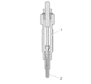
図2は、(1)において得られたセラミックヒータの縦断面図である。また、図1は、このセラミックヒータを組み込んだグロープラグの縦断面図である。このグロープラグ1は、図1のように発熱する部位である先端側にセラミックヒータ2を備える。また、このセラミックヒータ2は図2のように、基体21、発熱抵抗体22及び給電部23a、23bにより構成されている。
【0024】
基体21は窒化珪素焼結体からなり、埋設される発熱抵抗体22、及び給電部23a、23bは、この基体21によって保護されている。発熱抵抗体22はU字形の棒状体からなり、基体21に埋設される形態で配設されている。更に、この発熱抵抗体22には、導電成分及び絶縁成分が含有されている。また、タングステンからなる給電部23a、23bは図1のように、外部からセラミックヒータ2に供給される電力を基体21に埋設される発熱抵抗体22へ給電できるように、それぞれその一端は基体21の表面に位置し、他端は発熱抵抗体22の両端に接続されている。
【0025】
(3)抗折強度及び耐久性の評価
▲1▼抗折強度;JIS R 1601に準じて3点曲げ強度を測定した。スパンは20mmとし、クロスヘッド速度は0.5mm/分とした。
▲2▼耐久性;発熱抵抗体に通電し、セラミックヒータの表面において最高温となる部位の温度を1300℃又は1400℃とし、通電を1分間継続した後、通電を1分間停止し、この通電と通電の停止とを繰り返した。
結果を表1に併記する。
【0026】
【表1】

表1の結果によれば、本発明の範囲内である実験例1〜5のセラミックヒータでは、抗折強度の最少値は1205〜1290MPa、平均値は1285〜1350MPa、最大値は1360〜1420MPaであり、強度のばらつきが比較的小さく、特に、最少値が1100MPa、更には1200MPaを下回る強度の小さいものはないことが分かる。また、耐久性も、1300℃ばかりでなく1400℃においても10000サイクル繰り返し試験した場合に、断線等の問題はまったくなく、非常に優れていることが分かる。更に、本発明の範囲内である実験例6〜7では、抗折強度の平均値は1190〜1285MPaであり、耐久性も、1300℃では8500サイクルまでは断線せず、実用上、問題のないセラミックヒータが得られていることが分かる。
【0028】
尚、本発明においては、上記の実施例に限られず、目的、用途に応じて本発明の範囲内で種々変更した実施例とすることができる。即ち、MoSi2、TiN等、WC以外の導電成分であっても、Fe量が少量、例えば、0.05重量%以下である場合は、より優れた抗折強度を有し、且つ1400℃における10000サイクルの耐久試験によっても何ら問題を生ずることのないセラミックヒータとすることができる。また、本発明のセラミックヒータはグロープラグばかりでなく、暖房用等の各種ヒータにも使用することができる。
【0029】
【発明の効果】
本発明によれば、抗折強度が大きく、特定の温度における耐久性に優れたセラミックヒータとすることができる。また、本発明では、より優れた抗折強度を有し、且つ1400℃という高温における耐久性に優れたセラミッヒータとすることができる。また、本発明のグロープラグは、本発明のセラミックヒータを加熱源として備え、使用時、ヒータの断線等を生ずることがない。
【図面の簡単な説明】
【図1】セラミックヒータを用いたグロープラグを説明するための縦断面図である。
【図2】セラミックヒータを説明するための縦断面図である。
【符号の説明】
1;グロープラグ、2;セラミックヒータ、21;基体、22;発熱抵抗体、23a、23b;給電部。[0001]
BACKGROUND OF THE INVENTION
The present invention relates to a ceramic heater and a glow plug including the same. More specifically, the present invention suppresses a decrease in sinterability of a ceramic raw material such as a silicon nitride raw material due to Fe contained in a conductive component such as WC used for forming a heating resistor, and has an excellent bending strength and The present invention relates to a ceramic heater having durability and a glow plug including the ceramic heater. The ceramic heater of the present invention can be used in various applications in addition to a heat source for a glow plug of a diesel engine.
[0002]
[Prior art]
As a ceramic heater used for a glow plug or the like, a silicon nitride sintered body in which a heating resistor containing a conductive component such as WC is embedded is known. This WC or the like is generally fired using Co, Fe, Ni, Mo, Cr or the like in the field of cemented carbide. This firing can be performed at a relatively low temperature of about 1350 to 1550 ° C. However, the maximum use temperature of the obtained sintered body is also limited to 1000 ° C. or less, and cannot be used as a heater such as a glow plug used in a temperature range around 1200 ° C. or higher.
[0003]
Therefore, firing of the ceramic raw material for forming the insulating component contained in the heating resistor is possible as long as the sintering aid is used and the densification is not impaired. In general, a method of using a heater with a maximum operating temperature by using a small amount is practically used. However, since impurities contained in WC and the like reduce the sinterability of the ceramic raw material, the amount of sintering aid cannot be reduced sufficiently, and the maximum use temperature of the heater has been limited to 1300 ° C. In addition, the partial sintering failure due to the impurities causes variations in bending strength and durability, and the quality may not be stable.
[0004]
This type of ceramic heater is useful as a heat source for glow plugs. Normally, a rated battery voltage of 12V is directly applied to glow plugs used in diesel engines for passenger cars and the like, and 24V for large trucks and the like. It is necessary to suppress the battery voltage, and the battery voltage must be increased beyond 24V. However, when such a high voltage is applied to the glow plug, migration of the ceramic constituting the substrate of the ceramic heater is caused and ion migration at the grain boundary of the heating resistor is likely to occur. For this reason, the grain boundary component of the heating resistor moves to the substrate, and the structure of the heating resistor becomes rough. This causes breakage particularly when a high voltage exceeding 24 V is applied.
[0005]
[Problems to be solved by the invention]
The present invention solves the above-mentioned conventional problems, and suppresses a decrease in sinterability of ceramic raw materials such as silicon nitride raw materials due to Fe contained in the raw materials of conductive components such as WC, thereby stabilizing the quality. It is an object of the present invention to provide a ceramic heater having both excellent bending strength and durability and a glow plug including the same.
[0006]
[Means for Solving the Problems]
The ceramic heater of the present invention is a ceramic heater comprising a base made of a silicon nitride sintered body and a heating resistor embedded in the base, and the amount of Fe contained in the heating resistor is 0.0435 wt%. The heating resistor is composed of a conductive component WC and an insulating component made of a silicon nitride sintered body, and the Fe content in the conductive component is 0.075% by weight or less. And
[0007]
Further, the heating resistor is made of a conductive component and the insulating component, Fe content contained in the conductive component is 0.075 wt% or less. The amount of Fe contained in the heating resistor is substantially the same as the amount of Fe contained as an impurity in the raw material that becomes a conductive component after firing unless the Fe content is positively contained. And even if the amount ratio of the conductive component in the heat generating resistor is high, if the amount of Fe contained in the heat generating resistor is 0.0435 % by weight or less, a ceramic such as a silicon nitride raw material that forms an insulating component A decrease in the sinterability of the raw material is sufficiently suppressed.
[0008]
Furthermore, in the case of using the amount of Fe is small WC contained as an impurity as a conductive ingredient material, the amount of Fe contained in the conductive component may be 0.046 wt% or less. Thus, it is preferable that the amount of Fe contained in the conductive component is small, since a decrease in sinterability of a ceramic raw material such as a silicon nitride raw material that becomes an insulating component after firing can be suppressed sufficiently. In the present invention, the amount of Fe can be quantified with an X-ray microanalyzer.
[0009]
The “base” is usually made of a silicon nitride sintered body. This sintered body may be made of only silicon nitride, or may be mainly composed of silicon nitride and containing a small amount of aluminum nitride, alumina, or the like. Sialon may also be used.
[0010]
The “heating resistor” includes a conductive component and an insulating component.
As the conductive component, at least one of silicide, carbide, nitride, or the like of one or more metal elements selected from W, Ta, Nb, Ti, Mo, Zr, Hf, V, and Cr is fired, It is formed. The insulating component is usually made of a silicon nitride sintered body. In particular, the conductive component is preferably one whose thermal expansion coefficient is not significantly different from the silicon nitride sintered body constituting the substrate or the silicon nitride sintered body that is an insulating component. If the conductive component has a small difference in coefficient of thermal expansion, the occurrence of cracks in the substrate and the heating resistor when the heater is used can be suppressed. Examples of such a conductive component include WC, MoSi 2 , TiN, and WSi 2 . Further, the conductive component preferably has a high heat resistance because its melting point exceeds the operating temperature of the ceramic heater. If the melting point of the conductive component is high, the heat resistance of the heater in the operating temperature range is also improved.
[0011]
The quantity ratio between the conductive component and the insulating component is not particularly limited, but when the heating resistor is 100 parts by volume, the conductive component can be 15 to 40 parts by volume, and particularly 20 to 30 parts by volume. Can do.
[0012]
The ceramic heater of the present invention can be manufactured as follows.
As the raw material powder for the conductive component, a powder made of silicide, carbide or nitride of a metal element such as W, Ti and Mo is used. Further, ceramic raw material powder such as silicon nitride raw material powder and sintering aid powder are used as the raw material powder of the insulating component. As the sintering aid powder, rare earth oxide powder is frequently used, but powders of oxides and the like generally used in firing silicon nitride sintered bodies such as MgO and Al 2 O 3 —Y 2 O 3 are used. It can also be used. These sintering aid powders may be used alone or in combination of two or more. In addition, it is preferable to use a sintering aid powder such as Er 2 O 3 in which the grain boundary when sintered is a crystal phase, since the heat resistance becomes higher.
[0013]
These raw material powder for conductive component, ceramic raw material powder, and sintering aid powder are mixed at a predetermined quantitative ratio to prepare a mixed powder. This mixing can be performed by an ordinary method such as a wet process.
The conductive component raw material powder, the ceramic raw material powder and the sintering aid powder are 15 to 40 parts by volume, particularly 20 to 30 parts by volume, and the balance when the total amount of these is 100 parts by volume. Can be 85 to 60 parts by volume, particularly 80 to 70 parts by volume of the ceramic raw material powder and the sintering aid powder.
[0014]
The mixed powder thus prepared is mixed with an appropriate amount of binder and kneaded, granulated, and then used to form a molded body that becomes a heating resistor after firing by a method such as injection molding. be able to. A lead wire made of a metal such as tungsten is attached to a predetermined position of the formed body.
[0015]
Thereafter, this compact is embedded in the raw material powder for the substrate. Examples of the method include a method in which two half molds obtained by compacting a raw material powder for a substrate are prepared, a molded body is placed at a predetermined position between these half molds, and then press molding is performed. Next, by integrally pressing them to about 50 to 120 atm, a ceramic heater molded body in which a molded body to be a heating resistor is embedded in a powder molded body having a base shape is obtained. The ceramic heater molded body is housed in a pressing die made of graphite or the like, housed in a firing furnace, and subjected to hot press firing at a predetermined temperature for a required time, whereby a ceramic heater can be manufactured. The firing temperature and firing time are not particularly limited, but the firing temperature may be 1700-1850 ° C., and the firing time may be 30-180 minutes, particularly 60-120 minutes.
[0016]
The ceramic heater of the present invention is stable in quality and has both excellent bending strength and durability. That is, in the ceramic heater of the present invention, the bending strength measured in accordance with JIS R 1601 is 1000 MPa or more, and no disconnection occurs when energization at 1300 ° C. and stop of energization are repeated 5000 cycles. It can be a ceramic heater. Furthermore, when the bending strength is 1250 MPa or more and energization at 1400 ° C. and stop of energization are repeated 10,000 cycles, a ceramic heater that does not cause disconnection can be obtained.
[0017]
In the ceramic heater of the present invention, the bending strength can be 1000 to 1400 MPa, particularly 1100 to 1400 MPa, and further 1200 to 1400 MPa. The difference between the minimum value and the average value of the bending strength can be 100 MPa or less, particularly 80 MPa or less, and further 50 MPa or less. Further, the ratio of the difference between the average value of the bending strength and the minimum value to the average value can be 9% or less, particularly 7% or less, and further 5% or less.
[0018]
Further, the ceramic heater of the present invention is an excellent ceramic heater that does not cause disconnection or the like even when energization at 1300 ° C. and stop of energization are repeated 5000 cycles or more, particularly 8000 cycles or more, and even 10,000 cycles. be able to. In particular, in the ceramic heater of the present invention, even when energization at 1400 ° C. and stoppage of energization are repeated 5000 cycles or more, particularly 8000 cycles or more, and even 10,000 cycles, it has better durability without causing disconnection or the like It can be set as the ceramic heater which has.
[0019]
In the present invention, as described above, a ceramic heater having both excellent bending strength and durability can be obtained, the bending strength is 1000 to 1400 MPa, and energization and energization at 1300 ° C., particularly 1400 ° C. Even if it is stopped for 5000 cycles or more, an excellent ceramic heater that does not cause disconnection or the like can be obtained. In addition, the bending strength is 1100 to 1400 MPa, and an excellent ceramic heater that does not cause disconnection or the like even when energization at 1300 ° C., particularly 1400 ° C., and stopping of energization is repeated for 8000 cycles or more is also possible. it can. Further, the bending strength is 1200 to 1400 MPa, and an excellent ceramic heater that does not cause disconnection or the like even when the energization at 1300 ° C., particularly 1400 ° C., and the deactivation of the energization is repeated 10,000 cycles can be obtained.
[0020]
The glow plug of the present invention includes the ceramic heater of the present invention, and is characterized in that a voltage of 24 V or more is applied. In the ceramic heater of the present invention, the sintering aid used for forming the thermal resistor can be reduced, and the movement of grain boundary components can be suppressed. Therefore, a glow plug provided with this ceramic heater as a heat source is excellent in durability without causing problems such as disconnection of the heater during use. In this glow plug, the applied voltage is preferably 50 V or less, particularly 42 V or less, from the viewpoint of preventing electric shock of the human body.
[0021]
DETAILED DESCRIPTION OF THE INVENTION
Hereinafter, the ceramic heater of the present invention will be described in more detail with reference to examples.
(1) Fabrication of ceramic heater 10 wt% Er 2 O 3 powder and 5 wt% SiO 2 powder were blended as a sintering aid to 85 wt% silicon nitride raw material powder to obtain an insulating component raw material. . The insulating component raw material 42% by weight and the conductive component raw material 58% by weight (containing the Fe content shown in Table 1) were wet-mixed for 72 hours and then dried to obtain a mixed powder. It was. Thereafter, the mixed powder and the binder were put into a kneader and kneaded for 4 hours. Next, the obtained kneaded material was cut into pellets, and this was put into an injection molding machine to obtain a molded body to be a U-shaped heating resistor in which tungsten lead wires were fitted at both ends. .
[0022]
On the other hand, 83 wt% silicon nitride raw material powder is blended with 10 wt% Er 2 O 3 powder, 5 wt% SiO 2 powder and 2 wt% MoSi 2 powder as a sintering aid and wet mixed for 40 hours. The resulting product was granulated by a spray dryer method, and two halves were prepared by compacting the granulated product. Thereafter, the molded body to be a heating resistor is placed at a predetermined position between the two halves, press-molded and embedded, and then these are integrally pressed at a pressure of 70 atm. A ceramic heater was obtained. Next, this unfired ceramic heater was calcined at 600 ° C. to remove the binder, and a calcined body was obtained. Thereafter, the calcined body was set on a graphite pressing die and hot-press fired at 1800 ° C. for 1.5 hours in a nitrogen atmosphere to produce a ceramic heater.
[0023]
(2) Configuration of Ceramic Heater and Glow Plug Incorporating This Heater FIG. 2 is a longitudinal sectional view of the ceramic heater obtained in (1). FIG. 1 is a longitudinal sectional view of a glow plug incorporating this ceramic heater. The glow plug 1 includes a
[0024]
The
[0025]
(3) Evaluation of bending strength and durability (1) Folding strength; Three-point bending strength was measured according to JIS R 1601. The span was 20 mm and the crosshead speed was 0.5 mm / min.
(2) Durability: Energize the heating resistor, set the maximum temperature on the surface of the ceramic heater to 1300 ° C or 1400 ° C, continue energization for 1 minute, then stop energization for 1 minute. And the energization stop was repeated.
The results are also shown in Table 1.
[0026]
[Table 1]
According to the results of Table 1, in the ceramic heaters of Experimental Examples 1 to 5 within the scope of the present invention, the minimum value of the bending strength is 1205-1290 MPa, the average value is 1285 to 1350 MPa, and the maximum value is 1360 to 1420 MPa. It can be seen that there is a relatively small variation in strength, and in particular, there is no minimum strength of 1100 MPa or even a strength less than 1200 MPa. Further, it can be seen that the durability is very excellent with no problems such as disconnection when the test is repeated not only at 1300 ° C. but also at 1400 ° C. for 10,000 cycles. Furthermore, in Experimental Examples 6 to 7 within the scope of the present invention, the average value of the bending strength is 1190 to 1285 MPa, and the durability is not broken up to 8500 cycles at 1300 ° C., and there is no practical problem. It can be seen that a ceramic heater is obtained.
[0028]
In the present invention, the present invention is not limited to the above-described embodiments, and various modifications can be made within the scope of the present invention depending on the purpose and application. That is, even if it is a conductive component other than WC, such as MoSi 2 and TiN, when the amount of Fe is small, for example, 0.05% by weight or less, it has a better bending strength and at 1400 ° C. It is possible to provide a ceramic heater that does not cause any problems even in the endurance test of 10,000 cycles. The ceramic heater of the present invention can be used not only for glow plugs but also for various heaters for heating and the like.
[0029]
【The invention's effect】
According to the present invention, a ceramic heater having high bending strength and excellent durability at a specific temperature can be obtained. Moreover, in this invention, it can be set as the ceramic heater which has the more excellent bending strength, and was excellent in durability in 1400 degreeC high temperature. Further, the glow plug of the present invention comprises a ceramic heater of the present invention as a heat source, in use, never causing disconnection or the like of the heater.
[Brief description of the drawings]
FIG. 1 is a longitudinal sectional view for explaining a glow plug using a ceramic heater.
FIG. 2 is a longitudinal sectional view for explaining a ceramic heater.
[Explanation of symbols]
DESCRIPTION OF SYMBOLS 1; Glow plug, 2; Ceramic heater, 21; Base | substrate, 22; Heating resistor, 23a, 23b;
Claims (3)
Priority Applications (1)
| Application Number | Priority Date | Filing Date | Title |
|---|---|---|---|
| JP31153299A JP4262847B2 (en) | 1999-11-01 | 1999-11-01 | Ceramic heater and glow plug including the same |
Applications Claiming Priority (1)
| Application Number | Priority Date | Filing Date | Title |
|---|---|---|---|
| JP31153299A JP4262847B2 (en) | 1999-11-01 | 1999-11-01 | Ceramic heater and glow plug including the same |
Publications (2)
| Publication Number | Publication Date |
|---|---|
| JP2001132948A JP2001132948A (en) | 2001-05-18 |
| JP4262847B2 true JP4262847B2 (en) | 2009-05-13 |
Family
ID=18018381
Family Applications (1)
| Application Number | Title | Priority Date | Filing Date |
|---|---|---|---|
| JP31153299A Expired - Fee Related JP4262847B2 (en) | 1999-11-01 | 1999-11-01 | Ceramic heater and glow plug including the same |
Country Status (1)
| Country | Link |
|---|---|
| JP (1) | JP4262847B2 (en) |
-
1999
- 1999-11-01 JP JP31153299A patent/JP4262847B2/en not_active Expired - Fee Related
Also Published As
| Publication number | Publication date |
|---|---|
| JP2001132948A (en) | 2001-05-18 |
Similar Documents
| Publication | Publication Date | Title |
|---|---|---|
| JP3411498B2 (en) | Ceramic heater, method of manufacturing the same, and ceramic glow plug | |
| US5883360A (en) | Ceramic heater ceramic glow plug and method of manufacturing the ceramic heater | |
| KR100399114B1 (en) | Ceramic Heaters | |
| JP3889536B2 (en) | Ceramic heater, method for manufacturing the same, and glow plug including the ceramic heater | |
| EP1054577B1 (en) | Heating resistor, heating resistor for use in ceramic heater, and ceramic heater using the same | |
| JP3766786B2 (en) | Ceramic heater and glow plug including the same | |
| EP1282341A2 (en) | Ceramic heater and method for manufacturing the same | |
| JP4699816B2 (en) | Manufacturing method of ceramic heater and glow plug | |
| JP4562029B2 (en) | Ceramic heater, manufacturing method thereof, and glow plug | |
| JP3963412B2 (en) | Heating resistor for ceramic heater, ceramic heater, and method for manufacturing ceramic heater | |
| EP1120998B1 (en) | Ceramic heater & glow plug equipped with same | |
| JP4262847B2 (en) | Ceramic heater and glow plug including the same | |
| JP3664567B2 (en) | Ceramic heater and ceramic glow plug | |
| JP3807813B2 (en) | Ceramic heater and ceramic glow plug | |
| JP3874581B2 (en) | Ceramic heater and glow plug using the same | |
| JP3160226B2 (en) | Ceramic heater | |
| JP3877532B2 (en) | Ceramic heater and glow plug including the same | |
| JP2001132949A (en) | Ceramic heater and glow plug | |
| JP3115254B2 (en) | Ceramic heater | |
| JP2001132947A (en) | Ceramic heater and glow plug equipped with it | |
| JP4597352B2 (en) | Ceramic heater | |
| JP3689526B2 (en) | Ceramic heater | |
| JP2000173749A (en) | Ceramic heater heating resistor, ceramic heater, and manufacture of ceramic heater | |
| JP3903458B2 (en) | Ceramic heater and glow plug including the same | |
| JP2001153360A (en) | Ceramic heater and glow plug equipped with it |
Legal Events
| Date | Code | Title | Description |
|---|---|---|---|
| A977 | Report on retrieval |
Free format text: JAPANESE INTERMEDIATE CODE: A971007 Effective date: 20060323 |
|
| A131 | Notification of reasons for refusal |
Free format text: JAPANESE INTERMEDIATE CODE: A131 Effective date: 20060418 |
|
| A521 | Written amendment |
Free format text: JAPANESE INTERMEDIATE CODE: A523 Effective date: 20060614 |
|
| A02 | Decision of refusal |
Free format text: JAPANESE INTERMEDIATE CODE: A02 Effective date: 20060725 |
|
| A521 | Written amendment |
Free format text: JAPANESE INTERMEDIATE CODE: A523 Effective date: 20060919 |
|
| A911 | Transfer of reconsideration by examiner before appeal (zenchi) |
Free format text: JAPANESE INTERMEDIATE CODE: A911 Effective date: 20061106 |
|
| A912 | Removal of reconsideration by examiner before appeal (zenchi) |
Free format text: JAPANESE INTERMEDIATE CODE: A912 Effective date: 20061222 |
|
| RD02 | Notification of acceptance of power of attorney |
Free format text: JAPANESE INTERMEDIATE CODE: A7422 Effective date: 20080820 |
|
| A521 | Written amendment |
Free format text: JAPANESE INTERMEDIATE CODE: A523 Effective date: 20081219 |
|
| A01 | Written decision to grant a patent or to grant a registration (utility model) |
Free format text: JAPANESE INTERMEDIATE CODE: A01 |
|
| A61 | First payment of annual fees (during grant procedure) |
Free format text: JAPANESE INTERMEDIATE CODE: A61 Effective date: 20090210 |
|
| FPAY | Renewal fee payment (event date is renewal date of database) |
Free format text: PAYMENT UNTIL: 20120220 Year of fee payment: 3 |
|
| R150 | Certificate of patent or registration of utility model |
Free format text: JAPANESE INTERMEDIATE CODE: R150 |
|
| FPAY | Renewal fee payment (event date is renewal date of database) |
Free format text: PAYMENT UNTIL: 20120220 Year of fee payment: 3 |
|
| FPAY | Renewal fee payment (event date is renewal date of database) |
Free format text: PAYMENT UNTIL: 20120220 Year of fee payment: 3 |
|
| FPAY | Renewal fee payment (event date is renewal date of database) |
Free format text: PAYMENT UNTIL: 20120220 Year of fee payment: 3 |
|
| FPAY | Renewal fee payment (event date is renewal date of database) |
Free format text: PAYMENT UNTIL: 20130220 Year of fee payment: 4 |
|
| FPAY | Renewal fee payment (event date is renewal date of database) |
Free format text: PAYMENT UNTIL: 20130220 Year of fee payment: 4 |
|
| FPAY | Renewal fee payment (event date is renewal date of database) |
Free format text: PAYMENT UNTIL: 20140220 Year of fee payment: 5 |
|
| R250 | Receipt of annual fees |
Free format text: JAPANESE INTERMEDIATE CODE: R250 |
|
| R250 | Receipt of annual fees |
Free format text: JAPANESE INTERMEDIATE CODE: R250 |
|
| R250 | Receipt of annual fees |
Free format text: JAPANESE INTERMEDIATE CODE: R250 |
|
| LAPS | Cancellation because of no payment of annual fees |