JP4258979B2 - Toroidal type continuously variable transmission - Google Patents
Toroidal type continuously variable transmission Download PDFInfo
- Publication number
- JP4258979B2 JP4258979B2 JP2001021916A JP2001021916A JP4258979B2 JP 4258979 B2 JP4258979 B2 JP 4258979B2 JP 2001021916 A JP2001021916 A JP 2001021916A JP 2001021916 A JP2001021916 A JP 2001021916A JP 4258979 B2 JP4258979 B2 JP 4258979B2
- Authority
- JP
- Japan
- Prior art keywords
- trunnion
- supported
- continuously variable
- variable transmission
- casing
- Prior art date
- Legal status (The legal status is an assumption and is not a legal conclusion. Google has not performed a legal analysis and makes no representation as to the accuracy of the status listed.)
- Expired - Fee Related
Links
Images


Landscapes
- Friction Gearing (AREA)
- Mounting Of Bearings Or Others (AREA)
- Rolling Contact Bearings (AREA)
- Support Of The Bearing (AREA)
Description
【0001】
【発明の属する技術分野】
この発明は、例えば自動車用の変速機として用いるトロイダル型無段変速機に関する。
【0002】
【従来の技術】
例えば自動車用変速機として用いるダブルキャビティ式トロイダル型無段変速機は、図5及び図6に示すように構成されている。すなわち、ケーシング1の内側には入力軸2が回転自在に支持されている。入力軸2の外周には円管状の伝達軸3が入力軸2を同心に入力軸2に対する相対回転を自在に支持されている。
【0003】
伝達軸3の両端寄り部分には第1と第2の入力ディスク4,5が互いに内側面4a,5aを対向させた状態で、それぞれボールスプライン6を介して支持されている。従って、第1と第2の入力ディスク4,5はケーシング1の内側に互いに同心にかつ互いに同期して回転自在に支持されている。
【0004】
伝達軸3の中間部の周囲には第1と第2の出力ディスク7,8がスリーブ9を介して支持されている。スリーブ9は中間部の外周面に出力歯車10を一体に設けたもので、伝達軸3の外径よりも大きな内径を有し、ケーシング1内に設けた支持壁11に一対の転がり軸受12により伝達軸3と同心に回転自在に支持されている。
【0005】
第1と第2の出力ディスク7,8はスリーブ9の両端部にそれぞれの内側面7a,8aを互いに反対に向けた状態にスプライン係合されている。従って、第1の入力ディスク4と第1の出力ディスク7は互いに内側面4a,7aを対向させ、第2の入力ディスク5と第2の出力ディスク8は互いに内側面5a,8aを対向させた状態に回転自在に支持されている。
【0006】
ケーシング1の内面で第1と第2の出力ディスク7,8の側方位置には、両ディスク7,8を両側から挟む状態で一対のヨーク13a,13bが支持されている。一対のヨーク13a,13bは鋼等の金属のプレス加工あるいは鍛造加工により矩形状に形成されている。そして、ヨーク13a,13bの四隅には後述するトラニオン14の両端部に設けた枢軸16を揺動自在に支持するため、円形の支持孔18が、幅方向の中央部に円形の係止孔19が設けられている。
【0007】
一対のヨーク13a,13bはケーシング1の内面で互いに対向する部分に形成した支持ポスト20a,20bに若干の変位自在に支持されている。これら支持ポスト20a,20bはそれぞれ第1の入力ディスク4の内側面4aと第1の出力ディスク7の内側面7aとの間部分である第1キャビティ21、第2の入力ディスク5の内側面5aと第2の出力ディスク8の内側面8aとの間部分である第2キャビティ22にそれぞれ対向する状態に設けられている。
【0008】
従って、前記ヨーク13a,13bは各支持ポスト20a,20bに支持した状態で、各ヨーク13a,13bの一端部は第1キャビティ21の外周部分に、他端部は第2キャビティ22の外周部分にそれぞれ対向している。
【0009】
第1と第2のキャビティ21,22は同一構造であるため、第1キャビティ21のみについて説明すると、一対のトラニオン14が設けられている。トラニオン14の両端部には同心的に枢軸16が設けられ、これら枢軸16は一対のヨーク13a,13bの一端部に揺動及び軸方向に亘って変位自在に支持されている。すなわち、ヨーク13a,13bの一端部に形成した支持孔18の内側にラジアルニードル軸受26によって支持されている。ラジアルニードル軸受26は外周面が球状凸面であり、内周面が円筒面である外輪27と複数本のニードル28とから構成されている。
【0010】
トラニオン14の中間部にはそれぞれ円孔30が設けられている。各円孔30部分には変位軸31が支持されている。変位軸31はそれぞれ互いに平行でかつ偏心した支持軸部33と枢支軸部34を有している。このうちの支持軸部33は円孔30の内側にラジアルニードル軸受35を介して支持されている。また、枢支軸部34は周囲にパワーローラ36が別のラジアルニードル軸受38を介して支持されている。
【0011】
なお、第1と第2のキャビティ21,22毎に一対ずつ設けた変位軸31は第1と第2のキャビティ21,22毎に、入力軸2及び伝達軸3に対して180度反対側に位置して設けられている。また、変位軸31の各支持軸部34が各支持軸部33に対して偏心している方向は、第1と第2の入力ディスク4,5及び第1と第2の出力ディスク7,8の回転方向に関して同方向としている。また、偏心方向は入力軸2の配設方向に対して略直交する方向としている。従って、パワーローラ36は入力軸2及び伝達軸3の配設方向に亘る若干の変位自在に支持される。この結果、トロイダル型無段変速機により伝達するトルクの変動に基づく、構成部材の弾性変形量の変動等に起因して、パワーローラ36が入力軸2及び伝達軸3の軸方向に変位する傾向となった場合でも構成部材に無理な力を加えることなく、変位を吸収できる。
【0012】
さらに、前記パワーローラ36の外周面とトラニオン14の中間部内周面との間にはパワーローラ36の外側面から順に、スラスト玉軸受39と滑り軸受あるいはニードル軸受等のスラスト軸受40とが設けられている。このうちのスラスト玉軸受39はパワーローラ36に加わるスラスト方向の荷重を支承しつつ、これらパワーローラ36の回転を許容する。また、スラスト軸受40はパワーローラ36からスラスト玉軸受39の外輪41に加わるスラスト荷重を支承しつつ、枢支軸部34及び外輪41が前記支持軸部33を中心に揺動することを許容する。
【0013】
さらに、トラニオン14の一端部にはそれぞれ駆動ロッド42が結合され、これら駆動ロッド42の中間部外周面に駆動ピストン43が固着されている。この駆動ピストン43は駆動シリンダ44内に油密に嵌装されている。そして、駆動ピストン43がトラニオン14を軸方向に変位させるためのアクチュエータを構成している。
【0014】
また、入力軸2と第1の入力ディスク4との間にはローディングカム式の押圧装置45が設けられている。この押圧装置45は入力軸2の中間部にスプライン係合すると共に軸方向に亘る変位を阻止された状態で支持されて、入力軸2と共に回転するカム板46と、保持器47に転動自在に保持された複数のローラ48とを含んで構成している。そして、入力軸2の回転に基づいて第1の入力ディスク4を第2の入力ディスク5に向け押圧しつつ回転させる。
【0015】
前述のように構成されたトロイダル型無段変速機の運転時、入力軸2の回転は押圧装置45を介して第1の入力ディスク4に伝えられ、第1の入力ディスク4と第2の入力ディスク5とが互いに同期して回転する。第1の入力ディスク4及び第2の入力ディスク5の回転はパワーローラ36を介して第1と第2の出力ディスク7,8に伝えられる。第1と第2の出力ディスク7,8の回転は出力歯車10により取り出される。
【0016】
入力軸2と出力歯車10との間の回転速度比を変える場合には、制御弁(図示しない)の切替に基づいて第1と第2のキャビティ21,22に対応してそれぞれ一対ずつ設けられて駆動ピストン43を各キャビティ21,22毎に互いに逆方向に同じ距離だけ変位させる。
【0017】
これら駆動ピストン43の変位に伴って一対ずつ合計4個のトラニオン14がそれぞれ逆方向に変位し、一方のパワーローラ36が下側に、他方のパワーローラ36が上側にそれぞれ変位する。この結果、各パワーローラ36の周面と第1と第2の入力ディスク4,5の内側面4a,5a及び第1と第2の出力ディスク7,8の内側面7a,8aとの当接部に作用する、接線方向の力の向きが変化する。そして、その力の向きの変化に伴ってトラニオン14がヨーク13a,13bに枢支した枢軸16を中心として逆方向に揺動する。この結果、パワーローラ36の周面と第1と第2の入力ディスク4,5及び第1と第2の出力ディスク7,8との当接位置が変化し、入力軸2と出力歯車10の間の回転速度比が変化する。
【0018】
しかしながら、前述のように構成された従来のトロイダル型無段変速機は、トラニオン14をケーシング1の内側に支持ポスト20a,20b及びヨーク13a,13bを介して支持している。従って、部品点数が増大して部品製作、部品管理、組立作業が面倒になるだけでなく、トロイダル型無段変速機の高さ寸法が嵩み、小型、軽量化が図れないという問題がある。
【0019】
そこで、例えば、特開2000−9200号公報の図4に示すように、ヨークをケーシングの内側に直接固定するとともに、トラニオンの両端部に設けられた枢軸をボールスプラインを介して前記ヨークに上下方向に移動自在に支持した構成のものが開発された。
【0020】
前記構成によれば、ヨークをケーシングに直接固定しているために、部品点数の低減が図られ、部品製作、部品管理、組立作業の簡略化が図れると共に、トロイダル型無段変速機の高さ寸法を小さく、小型、軽量化が図れる。
【0021】
【発明が解決しようとする課題】
しかしながら、前述した特開2000−9200号公報のトロイダル型無段変速機は、トラニオンの枢軸にボールスプラインがあり、上下方向に動くことが可能な構造である。また、ボールスプラインの外輪が球面になっており、トラニオンが弾性変形した際にこじられないようになっている。さらに、ボールスプラインの内輪のニードルベアリングでトラニオンが枢軸を中心に傾転できるようになっている。
【0022】
従って、トラニオンの支持構造が複雑であり、部品点数も多くなっている。また、上部のボールスプラインにボールを組み込む際、ケーシングに穴を開けなければならず、ケーシングの剛性を低下させるという問題がある。さらに、トラニオンを上下方向に移動可能にするボールスプラインは、組立ての際のボールの位置によりボールの運動は滑りと転がりが共存することになる。一般に転がり運動と滑り運動では摩擦係数が少なくとも一桁違い、上下方向の移動に滑りが共存することになれば、各トラニオンで上下方向の力が不均一となる。
【0023】
この発明は、前記事情に着目してなされたもので、その目的とするところは、トラニオンからボールスプラインをなくし、部品点数の減少及び組立ての容易化を図ると共に、各トラニオンの上下方向の動きを均一化できるトロイダル型無段変速機を提供することにある。
【0024】
【課題を解決するための手段】
この発明は、前記目的を達成するために、請求項1は、ケーシングと、このケーシングの内側に互いに同心に、かつ互いに独立して回転自在に支持された入力ディスク及び出力ディスクと、前記入力ディスク及び出力ディスクの中心軸の方向に対して直角方向となる捩れの位置に存在する、互いに同心もしくは平行な偶数本の枢軸を有し、この枢軸を中心として揺動する複数個のトラニオンと、これらトラニオンの内側面から突出する変位軸と、これら変位軸に回転自在に支持された状態で、前記入力ディスク及び出力ディスクの内側面同士の間に挟持された複数個のパワーローラと、これら各パワーローラの側方に位置する前記ケーシングに直接固定され前記枢軸を支持する支持手段とを備えたトロイダル型無段変速機において、前記支持手段に、前記トラニオンの枢軸を軸方向及び傾転方向に変位自在に支持し、前記トラニオンの枢軸は、前記支持手段にニードルベアリングを介して支持し、このニードルベアリングは内輪及び外輪が球面形状の球面ベアリングで支持したことを特徴とする。
【0026】
請求項2は、請求項 1の前記球面ベアリングの外輪は、その球面の一部に切欠部を有し、この切欠部から前記内輪が圧入されて内外輪が一体に形成されていることを特徴とする。
【0027】
前記構成によれば、各トラニオンの上下方向の動きが円滑であり、力を各トラニオンで均一化することが可能となる。さらに、トラニオンの枢軸が上下方向に変位するときには同時にトラニオンの枢軸を中心に回転するため、若干の滑りがあるが、転がり運動となる。よって、単純な滑り運動より摩擦力は大幅に低減することとなり、変速の際に同期・安定性が向上する。
【0028】
【発明の実施の形態】
以下、この発明の各実施の形態を図面に基づいて説明するが、従来と同一構成部分は同一番号を付して説明を省略する。
【0029】
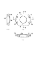
図1及び図2は第1の実施形態を示し、図1は図5のA−A線に相当する断面図、図2はニードルベアリングの外輪を示し、(a)は平面図、(b)はB−B線に沿う断面図、(c)はC−C線に沿う断面図である。
【0030】
図1に示すように、ケーシング1の内側で互いに対向する部分には支持手段としての上部ヨーク51と下部ヨーク52がそれぞれ直接固定されている。上部ヨーク51及び下部ヨーク52にはニードルベアリング53が設けられ、このニードルベアリング53は球面ベアリング50に支持され、トラニオン14の枢軸16を軸方向(上下方向)と傾転方向に変位自在に支持している。
【0031】
すなわち、球面ベアリング50は、内輪54と外輪55を有しており、内外輪54,55には互いに球面接合する球面54a,55aが設けられている。外輪55の両端部には、図2にも示すように、複数個のボルト穴56が設けられ、外輪55はボルト穴56に挿通したボルト57によってそれぞれ上部ヨーク51及び下部ヨーク52に固定されている。本実施形態では、上部ヨーク51及び下部ヨーク52の穴と球面ベアリング50の外輪55とは中間バメ程度の嵌め合いによりケーシング1に対して精度良く位置決めされている。なお、球面ベアリング50の位置が各トラニオン14の位置を決めるので、球面ベアリング50は上部ヨーク51及び下部ヨーク52に対して位置決めピン等によって正確に位置決めすることも可能である。外輪55の内周面の2箇所には切欠部58が設けられ、この切欠部58から内輪54を圧入することにより、内外輪54,55が一体化されている。
【0032】
そして、球面ベアリング50の内輪54にはトラニオン14の枢軸16が支持されている。枢軸16はニードルベアリング53の転動面となっているため、高周波焼入れ等の熱処理によって硬度を上げている。さらに、上部ヨーク51及び下部ヨーク52には潤滑油通路59が設けられ、この潤滑油通路59は球面ベアリング50、ニードルベアリング53に連通しており、外輪55及び枢軸16には油穴が設けられ、球面ベアリング50、ニードルベアリング53に十分な潤滑油が供給されるようになっている。また、潤滑油通路59はトラニオン14のラジアルニードル軸受35まで連通している。
【0033】
さらに、トラニオン14は上下方向に変位自在であるため、外輪55の下面とトラニオン14の上面との間A部、外輪55の上面とトラニオン14の下面との間B部、外輪55の下面とセーフティケーブル用滑車60の上面との間C部及びセーフティケーブル用滑車60と下部ヨーク52との間D部にはトラニオン14の上下ストローク分の隙間が設けられている。トラニオン14のストローク量は駆動ピストン43のストローク量できめるため、A、B、C、D部の隙間は駆動ピストン43のストロークE、Fより若干大きめに設計され、トラニオン14の上下方向の変位時の干渉を防止している。
【0034】
このように構成されたトロイダル型無段変速機のトラニオン14部分の組立て順序について説明すると、上部ヨーク51と球面ベアリング50の内外輪54,55は一体でケーシング1に組み込まれる。次に、パワーローラ36を備えたトラニオン14の枢軸16が球面ベアリング50の内輪54に組み込まれる。最後に、球面ベアリング50の内外輪54,55と一体化した下部ヨーク52がケーシング1の下方から組み込まれる。従って、従来のようにケーシング1に穴を開けることなく、組立てが可能となり、ケーシング1の剛性を低下させることがない。
【0035】
また、従来、トラニオンを上下方向に移動可能にするボールスプラインは、組立ての際のボールの位置によりボールの運動は滑りと転がりが共存することになる。トラニオンを上下方向に移動可能にするボールスプラインは、組立ての際のボールの位置によりボールの運動は滑りと転がりが共存することになり、各トラニオンで上下方向の力が不均一であったが、前述のように構成されたトロイダル型無段変速機によれば、各トラニオン14の上下方向の動きが一つの運動だけであり、力を各トラニオン14で均一化することが可能となる。さらに、トラニオン14の枢軸16が上下方向に変位するときには同時にトラニオン14の枢軸16を中心に回転するため、若干の滑りがあるが、転がり運動となる。よって、単純な滑り運動より摩擦力は大幅に低減することとなり、変速の際に同期・安定性が向上する。
【0036】
図3はこの発明の第2の実施形態を示し、第1の実施形態と同一構成部分は同一番号を付して説明を省略する。本実施形態は、上部ヨーク51及び下部ヨーク52と球面ベアリング50の外輪55を一体に形成したものであり、外輪55をボルト57によって上部ヨーク51及び下部ヨーク52に固定する手間が省けると共に、部品点数の減少が図れる。
【0037】
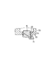
図4はこの発明の第3の実施形態を示し、第1の実施形態と同一構成部分は同一番号を付して説明を省略する。第1の実施形態においては、トラニオン14の上下方向の変位の際にはトラニオン14の枢軸16とニードルベアリング53との間で摺動するようにしたが、本実施形態は、トラニオン14の上下方向の変位をニードルベアリング53と球面ベアリング50の内輪54との間で摺動するようにしたものである。
【0038】
【発明の効果】
以上説明したように、この発明によれば、支持手段にトラニオンの枢軸を軸方向及び傾転方向に変位自在に支持したことを特徴とする。従って、部品点数の減少及び組立ての容易化を図ることができる。また、トラニオンが上下方向に動く際には同時にトラニオン軸を中心に回転する、転がり運動となり、摩擦力が大幅に低減され、各トラニオンの上下方向の動きを均一化でき、変速の際に同期・安定性が向上するという効果がある。
【図面の簡単な説明】
【図1】この発明の第1の実施形態におけるトロイダル型無段変速機を示し、図5のA−A線に相当する断面図。
【図2】同実施形態における球面ベアリングの外輪を示し、(a)は平面図、(b)はB−B線に沿う断面図、(c)はC−C線に沿う断面図。
【図3】この発明の第2の実施形態におけるトロイダル型無段変速機を示し、図 のA−A線に相当する断面図。
【図4】この発明の第3の実施形態におけるトラニオンの枢軸の支持構造を示す断面図。
【図5】従来のダブルキャビティ式トロイダル型無段変速機の縦断側面図。
【図6】図5のA−A線に沿う断面図。
【符号の説明】
1…ケーシング
2…入力軸
4,5…入力ディスク
7,8…出力ディスク
14…トラニオン
16…枢軸
36…パワーローラ
50…球面ベアリング
51…上部ヨーク
52…下部ヨーク
53…ニードルベアリング
54…内輪
55…外輪[0001]
BACKGROUND OF THE INVENTION
The present invention relates to a toroidal continuously variable transmission used as a transmission for an automobile, for example.
[0002]
[Prior art]
For example, a double-cavity toroidal continuously variable transmission used as a transmission for an automobile is configured as shown in FIGS. That is, the
[0003]
First and
[0004]
Around the intermediate portion of the
[0005]
The first and
[0006]
A pair of
[0007]
The pair of
[0008]
Therefore, with the
[0009]
Since the first and
[0010]
A
[0011]
The pair of
[0012]
Further, a thrust ball bearing 39 and a thrust bearing 40 such as a sliding bearing or a needle bearing are provided between the outer peripheral surface of the
[0013]
Further, a
[0014]
A loading cam
[0015]
During operation of the toroidal type continuously variable transmission configured as described above, the rotation of the
[0016]
When the rotational speed ratio between the
[0017]
Along with the displacement of these
[0018]
However, the conventional toroidal-type continuously variable transmission configured as described above supports the
[0019]
Therefore, for example, as shown in FIG. 4 of Japanese Patent Laid-Open No. 2000-9200, the yoke is directly fixed to the inside of the casing, and the pivots provided at both ends of the trunnion are vertically moved to the yoke via the ball spline. A structure that can be moved freely is developed.
[0020]
According to the above configuration, since the yoke is directly fixed to the casing, the number of parts can be reduced, the production of parts, the management of parts, and the assembly work can be simplified, and the height of the toroidal continuously variable transmission can be achieved. Small size, small size and light weight.
[0021]
[Problems to be solved by the invention]
However, the above-described toroidal-type continuously variable transmission disclosed in Japanese Patent Application Laid-Open No. 2000-9200 has a ball spline on the pivot shaft of the trunnion and has a structure that can move in the vertical direction. Further, the outer ring of the ball spline has a spherical surface so that it is not twisted when the trunnion is elastically deformed. Further, the trunnion can be tilted about the pivot axis by the needle bearing of the inner ring of the ball spline.
[0022]
Accordingly, the trunnion support structure is complicated and the number of parts is increased. Further, when a ball is incorporated into the upper ball spline, a hole must be formed in the casing, which causes a problem of reducing the rigidity of the casing. Further, in the ball spline that allows the trunnion to move in the vertical direction, the movement of the ball coexists with sliding and rolling depending on the position of the ball at the time of assembly. In general, when the rolling motion and the sliding motion have a friction coefficient that differs by at least an order of magnitude, and the slip coexists in the vertical movement, the vertical force is non-uniform in each trunnion.
[0023]
The present invention has been made paying attention to the above circumstances, and the object thereof is to eliminate the ball spline from the trunnion, to reduce the number of parts and to facilitate the assembly, and to make the movement of each trunnion in the vertical direction. An object is to provide a toroidal type continuously variable transmission which can be made uniform.
[0024]
[Means for Solving the Problems]
In order to achieve the above object, the present invention provides a casing, an input disk and an output disk that are rotatably supported concentrically and independently of each other inside the casing, and the input disk. And a plurality of trunnions having an even number of pivots that are concentric or parallel to each other and are located at a torsional position perpendicular to the direction of the central axis of the output disk, and swing about the pivot axis, and A displacement shaft projecting from the inner surface of the trunnion, a plurality of power rollers sandwiched between the inner surfaces of the input disk and the output disk in a state of being rotatably supported by the displacement shaft, A toroidal-type continuously variable transmission including a support means that is directly fixed to the casing located on a side of a roller and supports the pivot; The stage, displaced freely supports pivot of the trunnions in the axial direction and tilting direction, axis of the trunnion, and supported via a needle bearing on the support means, the needle bearing inner ring and the outer ring is spherical It is supported by a spherical bearing .
[0026]
According to a second aspect of the present invention, the outer ring of the spherical bearing of the first aspect has a notch in a part of the spherical surface, and the inner ring is press-fitted from the notch and the inner and outer rings are integrally formed. And
[0027]
According to the said structure, the vertical motion of each trunnion is smooth, and it becomes possible to equalize force with each trunnion. Further, when the trunnion pivot is displaced in the vertical direction, it simultaneously rotates around the trunnion pivot, so that there is a slight slip but a rolling motion. Therefore, the frictional force is greatly reduced compared with a simple sliding motion, and synchronization / stability is improved at the time of shifting.
[0028]
DETAILED DESCRIPTION OF THE INVENTION
Hereinafter, embodiments of the present invention will be described with reference to the drawings, but the same components as those in the prior art will be denoted by the same reference numerals and description thereof will be omitted.
[0029]
1 and 2 show a first embodiment, FIG. 1 is a cross-sectional view corresponding to line AA in FIG. 5, FIG. 2 shows an outer ring of a needle bearing, (a) is a plan view, and (b). Is a sectional view taken along line BB, and (c) is a sectional view taken along line CC.
[0030]
As shown in FIG. 1, an
[0031]
That is, the
[0032]
The
[0033]
Further, since the
[0034]
The assembly order of the
[0035]
Conventionally, a ball spline that allows the trunnion to move in the vertical direction has both the sliding and rolling of the movement of the ball depending on the position of the ball during assembly. The ball spline that allows the trunnion to move in the vertical direction, the movement of the ball coexists with sliding and rolling depending on the position of the ball at the time of assembly, the vertical force in each trunnion was uneven, According to the toroidal-type continuously variable transmission configured as described above, each
[0036]
FIG. 3 shows a second embodiment of the present invention, and the same components as those of the first embodiment are denoted by the same reference numerals and description thereof is omitted. In this embodiment, the
[0037]
FIG. 4 shows a third embodiment of the present invention. The same components as those of the first embodiment are denoted by the same reference numerals, and description thereof is omitted. In the first embodiment, when the
[0038]
【The invention's effect】
As described above, according to the present invention, the pivot shaft of the trunnion is supported by the supporting means so as to be freely displaceable in the axial direction and the tilting direction. Therefore, it is possible to reduce the number of parts and facilitate assembly. In addition, when the trunnion moves up and down, it simultaneously rotates around the trunnion axis, and it becomes a rolling motion, the frictional force is greatly reduced, the vertical movement of each trunnion can be made uniform, There is an effect that stability is improved.
[Brief description of the drawings]
FIG. 1 is a cross-sectional view showing a toroidal continuously variable transmission according to a first embodiment of the present invention and corresponding to the line AA in FIG. 5;
2A and 2B show an outer ring of a spherical bearing in the same embodiment, wherein FIG. 2A is a plan view, FIG. 2B is a cross-sectional view taken along line BB, and FIG. 2C is a cross-sectional view taken along line CC.
FIG. 3 is a sectional view showing a toroidal-type continuously variable transmission according to a second embodiment of the present invention and corresponding to the AA line in the figure.
FIG. 4 is a sectional view showing a support structure for a pivot shaft of a trunnion according to a third embodiment of the present invention.
FIG. 5 is a longitudinal side view of a conventional double cavity toroidal continuously variable transmission.
6 is a cross-sectional view taken along line AA in FIG.
[Explanation of symbols]
DESCRIPTION OF
Claims (2)
前記支持手段に、前記トラニオンの枢軸を軸方向及び傾転方向に変位自在に支持し、
前記トラニオンの枢軸は、前記支持手段にニードルベアリングを介して支持し、このニードルベアリングは内輪及び外輪が球面形状の球面ベアリングで支持したことを特徴とするトロイダル型無段変速機。A casing, an input disk and an output disk supported concentrically and independently of each other inside the casing, and a torsion that is perpendicular to the direction of the central axis of the input disk and the output disk A plurality of trunnions that exist at a position and have an even number of concentric or parallel pivots, swing around the pivots, displacement shafts that project from the inner surface of the trunnions, and freely rotate on these displacement shafts In a state of being supported by the plurality of power rollers, the plurality of power rollers sandwiched between the inner surfaces of the input disk and the output disk, and the pivot shaft that is directly fixed to the casing located on the side of each of the power rollers is supported. A toroidal-type continuously variable transmission provided with supporting means for
The pivot means of the trunnion is supported by the support means so as to be freely displaceable in the axial direction and the tilt direction ,
A toroidal continuously variable transmission characterized in that the pivot shaft of the trunnion is supported by the support means via a needle bearing, and the needle bearing is supported by a spherical bearing having an inner ring and an outer ring .
Priority Applications (2)
| Application Number | Priority Date | Filing Date | Title |
|---|---|---|---|
| JP2001021916A JP4258979B2 (en) | 2001-01-30 | 2001-01-30 | Toroidal type continuously variable transmission |
| US10/058,032 US7004882B2 (en) | 2001-01-30 | 2002-01-29 | Toroidal-type continuously variable transmission |
Applications Claiming Priority (1)
| Application Number | Priority Date | Filing Date | Title |
|---|---|---|---|
| JP2001021916A JP4258979B2 (en) | 2001-01-30 | 2001-01-30 | Toroidal type continuously variable transmission |
Publications (3)
| Publication Number | Publication Date |
|---|---|
| JP2002227951A JP2002227951A (en) | 2002-08-14 |
| JP2002227951A5 JP2002227951A5 (en) | 2006-01-26 |
| JP4258979B2 true JP4258979B2 (en) | 2009-04-30 |
Family
ID=18887398
Family Applications (1)
| Application Number | Title | Priority Date | Filing Date |
|---|---|---|---|
| JP2001021916A Expired - Fee Related JP4258979B2 (en) | 2001-01-30 | 2001-01-30 | Toroidal type continuously variable transmission |
Country Status (1)
| Country | Link |
|---|---|
| JP (1) | JP4258979B2 (en) |
-
2001
- 2001-01-30 JP JP2001021916A patent/JP4258979B2/en not_active Expired - Fee Related
Also Published As
| Publication number | Publication date |
|---|---|
| JP2002227951A (en) | 2002-08-14 |
Similar Documents
| Publication | Publication Date | Title |
|---|---|---|
| JPH0637223Y2 (en) | Friction wheel type continuously variable transmission | |
| JP3879913B2 (en) | Toroidal continuously variable transmission | |
| JP2003301907A (en) | Toroidal continuously variable transmission | |
| JP4258979B2 (en) | Toroidal type continuously variable transmission | |
| JP4941712B2 (en) | Toroidal continuously variable transmission | |
| JP3480135B2 (en) | Toroidal type continuously variable transmission | |
| JPH1151135A (en) | Toroidal type continuously variable transmission | |
| JP5803188B2 (en) | Toroidal continuously variable transmission | |
| JP4923989B2 (en) | Toroidal continuously variable transmission | |
| JP3758146B2 (en) | Toroidal continuously variable transmission | |
| JP4103228B2 (en) | Toroidal continuously variable transmission | |
| JP2005121045A (en) | Toroidal continuously variable transmission | |
| JP4972931B2 (en) | Toroidal continuously variable transmission | |
| JP2001304366A (en) | Toroidal-type continuously variable transmission | |
| US7004882B2 (en) | Toroidal-type continuously variable transmission | |
| JP4605460B2 (en) | Toroidal continuously variable transmission | |
| JP2024097392A (en) | Toroidal type non-stage transmission | |
| JP3758139B2 (en) | Toroidal continuously variable transmission | |
| JP6421462B2 (en) | Toroidal continuously variable transmission | |
| JP2000291756A (en) | Toroidal type continuously variable transmission | |
| JP2008111488A (en) | Toroidal type continuously variable transmission | |
| JP4605497B2 (en) | Toroidal continuously variable transmission | |
| JP2006009981A (en) | Toroidal type continuously variable transmission | |
| JP4702602B2 (en) | Toroidal continuously variable transmission | |
| JP5516859B2 (en) | Toroidal continuously variable transmission |
Legal Events
| Date | Code | Title | Description |
|---|---|---|---|
| A521 | Written amendment |
Free format text: JAPANESE INTERMEDIATE CODE: A523 Effective date: 20051201 |
|
| A621 | Written request for application examination |
Free format text: JAPANESE INTERMEDIATE CODE: A621 Effective date: 20051201 |
|
| A977 | Report on retrieval |
Free format text: JAPANESE INTERMEDIATE CODE: A971007 Effective date: 20080625 |
|
| A131 | Notification of reasons for refusal |
Free format text: JAPANESE INTERMEDIATE CODE: A131 Effective date: 20080701 |
|
| A521 | Written amendment |
Free format text: JAPANESE INTERMEDIATE CODE: A523 Effective date: 20080901 |
|
| TRDD | Decision of grant or rejection written | ||
| A01 | Written decision to grant a patent or to grant a registration (utility model) |
Free format text: JAPANESE INTERMEDIATE CODE: A01 Effective date: 20090120 |
|
| A01 | Written decision to grant a patent or to grant a registration (utility model) |
Free format text: JAPANESE INTERMEDIATE CODE: A01 |
|
| A61 | First payment of annual fees (during grant procedure) |
Free format text: JAPANESE INTERMEDIATE CODE: A61 Effective date: 20090202 |
|
| FPAY | Renewal fee payment (event date is renewal date of database) |
Free format text: PAYMENT UNTIL: 20120220 Year of fee payment: 3 |
|
| R150 | Certificate of patent or registration of utility model |
Free format text: JAPANESE INTERMEDIATE CODE: R150 |
|
| FPAY | Renewal fee payment (event date is renewal date of database) |
Free format text: PAYMENT UNTIL: 20130220 Year of fee payment: 4 |
|
| FPAY | Renewal fee payment (event date is renewal date of database) |
Free format text: PAYMENT UNTIL: 20130220 Year of fee payment: 4 |
|
| FPAY | Renewal fee payment (event date is renewal date of database) |
Free format text: PAYMENT UNTIL: 20140220 Year of fee payment: 5 |
|
| LAPS | Cancellation because of no payment of annual fees |