JP4256255B2 - Furnace and steam reforming process - Google Patents
Furnace and steam reforming process Download PDFInfo
- Publication number
- JP4256255B2 JP4256255B2 JP2003501789A JP2003501789A JP4256255B2 JP 4256255 B2 JP4256255 B2 JP 4256255B2 JP 2003501789 A JP2003501789 A JP 2003501789A JP 2003501789 A JP2003501789 A JP 2003501789A JP 4256255 B2 JP4256255 B2 JP 4256255B2
- Authority
- JP
- Japan
- Prior art keywords
- catalyst
- steam reforming
- reforming
- tube
- steam
- Prior art date
- Legal status (The legal status is an assumption and is not a legal conclusion. Google has not performed a legal analysis and makes no representation as to the accuracy of the status listed.)
- Expired - Fee Related
Links
Images


Classifications
-
- B—PERFORMING OPERATIONS; TRANSPORTING
- B01—PHYSICAL OR CHEMICAL PROCESSES OR APPARATUS IN GENERAL
- B01J—CHEMICAL OR PHYSICAL PROCESSES, e.g. CATALYSIS OR COLLOID CHEMISTRY; THEIR RELEVANT APPARATUS
- B01J8/00—Chemical or physical processes in general, conducted in the presence of fluids and solid particles; Apparatus for such processes
- B01J8/008—Details of the reactor or of the particulate material; Processes to increase or to retard the rate of reaction
-
- B—PERFORMING OPERATIONS; TRANSPORTING
- B01—PHYSICAL OR CHEMICAL PROCESSES OR APPARATUS IN GENERAL
- B01J—CHEMICAL OR PHYSICAL PROCESSES, e.g. CATALYSIS OR COLLOID CHEMISTRY; THEIR RELEVANT APPARATUS
- B01J8/00—Chemical or physical processes in general, conducted in the presence of fluids and solid particles; Apparatus for such processes
- B01J8/02—Chemical or physical processes in general, conducted in the presence of fluids and solid particles; Apparatus for such processes with stationary particles, e.g. in fixed beds
- B01J8/06—Chemical or physical processes in general, conducted in the presence of fluids and solid particles; Apparatus for such processes with stationary particles, e.g. in fixed beds in tube reactors; the solid particles being arranged in tubes
- B01J8/062—Chemical or physical processes in general, conducted in the presence of fluids and solid particles; Apparatus for such processes with stationary particles, e.g. in fixed beds in tube reactors; the solid particles being arranged in tubes being installed in a furnace
-
- C—CHEMISTRY; METALLURGY
- C01—INORGANIC CHEMISTRY
- C01B—NON-METALLIC ELEMENTS; COMPOUNDS THEREOF; METALLOIDS OR COMPOUNDS THEREOF NOT COVERED BY SUBCLASS C01C
- C01B3/00—Hydrogen; Gaseous mixtures containing hydrogen; Separation of hydrogen from mixtures containing it; Purification of hydrogen
- C01B3/02—Production of hydrogen or of gaseous mixtures containing a substantial proportion of hydrogen
- C01B3/32—Production of hydrogen or of gaseous mixtures containing a substantial proportion of hydrogen by reaction of gaseous or liquid organic compounds with gasifying agents, e.g. water, carbon dioxide, air
- C01B3/34—Production of hydrogen or of gaseous mixtures containing a substantial proportion of hydrogen by reaction of gaseous or liquid organic compounds with gasifying agents, e.g. water, carbon dioxide, air by reaction of hydrocarbons with gasifying agents
- C01B3/38—Production of hydrogen or of gaseous mixtures containing a substantial proportion of hydrogen by reaction of gaseous or liquid organic compounds with gasifying agents, e.g. water, carbon dioxide, air by reaction of hydrocarbons with gasifying agents using catalysts
- C01B3/384—Production of hydrogen or of gaseous mixtures containing a substantial proportion of hydrogen by reaction of gaseous or liquid organic compounds with gasifying agents, e.g. water, carbon dioxide, air by reaction of hydrocarbons with gasifying agents using catalysts the catalyst being continuously externally heated
-
- B—PERFORMING OPERATIONS; TRANSPORTING
- B01—PHYSICAL OR CHEMICAL PROCESSES OR APPARATUS IN GENERAL
- B01J—CHEMICAL OR PHYSICAL PROCESSES, e.g. CATALYSIS OR COLLOID CHEMISTRY; THEIR RELEVANT APPARATUS
- B01J2208/00—Processes carried out in the presence of solid particles; Reactors therefor
- B01J2208/00008—Controlling the process
- B01J2208/00654—Controlling the process by measures relating to the particulate material
- B01J2208/0069—Attrition
-
- B—PERFORMING OPERATIONS; TRANSPORTING
- B01—PHYSICAL OR CHEMICAL PROCESSES OR APPARATUS IN GENERAL
- B01J—CHEMICAL OR PHYSICAL PROCESSES, e.g. CATALYSIS OR COLLOID CHEMISTRY; THEIR RELEVANT APPARATUS
- B01J2208/00—Processes carried out in the presence of solid particles; Reactors therefor
- B01J2208/00796—Details of the reactor or of the particulate material
- B01J2208/00884—Means for supporting the bed of particles, e.g. grids, bars, perforated plates
-
- C—CHEMISTRY; METALLURGY
- C01—INORGANIC CHEMISTRY
- C01B—NON-METALLIC ELEMENTS; COMPOUNDS THEREOF; METALLOIDS OR COMPOUNDS THEREOF NOT COVERED BY SUBCLASS C01C
- C01B2203/00—Integrated processes for the production of hydrogen or synthesis gas
- C01B2203/08—Methods of heating or cooling
- C01B2203/0805—Methods of heating the process for making hydrogen or synthesis gas
- C01B2203/0811—Methods of heating the process for making hydrogen or synthesis gas by combustion of fuel
- C01B2203/0816—Heating by flames
-
- C—CHEMISTRY; METALLURGY
- C01—INORGANIC CHEMISTRY
- C01B—NON-METALLIC ELEMENTS; COMPOUNDS THEREOF; METALLOIDS OR COMPOUNDS THEREOF NOT COVERED BY SUBCLASS C01C
- C01B2203/00—Integrated processes for the production of hydrogen or synthesis gas
- C01B2203/08—Methods of heating or cooling
- C01B2203/0805—Methods of heating the process for making hydrogen or synthesis gas
- C01B2203/0811—Methods of heating the process for making hydrogen or synthesis gas by combustion of fuel
- C01B2203/0822—Methods of heating the process for making hydrogen or synthesis gas by combustion of fuel the fuel containing hydrogen
-
- C—CHEMISTRY; METALLURGY
- C01—INORGANIC CHEMISTRY
- C01B—NON-METALLIC ELEMENTS; COMPOUNDS THEREOF; METALLOIDS OR COMPOUNDS THEREOF NOT COVERED BY SUBCLASS C01C
- C01B2203/00—Integrated processes for the production of hydrogen or synthesis gas
- C01B2203/08—Methods of heating or cooling
- C01B2203/0805—Methods of heating the process for making hydrogen or synthesis gas
- C01B2203/0866—Methods of heating the process for making hydrogen or synthesis gas by combination of different heating methods
-
- Y—GENERAL TAGGING OF NEW TECHNOLOGICAL DEVELOPMENTS; GENERAL TAGGING OF CROSS-SECTIONAL TECHNOLOGIES SPANNING OVER SEVERAL SECTIONS OF THE IPC; TECHNICAL SUBJECTS COVERED BY FORMER USPC CROSS-REFERENCE ART COLLECTIONS [XRACs] AND DIGESTS
- Y02—TECHNOLOGIES OR APPLICATIONS FOR MITIGATION OR ADAPTATION AGAINST CLIMATE CHANGE
- Y02P—CLIMATE CHANGE MITIGATION TECHNOLOGIES IN THE PRODUCTION OR PROCESSING OF GOODS
- Y02P20/00—Technologies relating to chemical industry
- Y02P20/10—Process efficiency
- Y02P20/129—Energy recovery, e.g. by cogeneration, H2recovery or pressure recovery turbines
Description
本発明は水蒸気改質炉および炭化水素原料の水蒸気改質を行って改質ガス混合物、すなわち水素と酸化炭素類の混合物を製造する方法に関する。特に、垂直改質管を有する水蒸気改質炉と、このような炉を用いた水蒸気改質プロセスに関する。 The present invention relates to a steam reforming furnace and a method for producing a reformed gas mixture, that is, a mixture of hydrogen and carbon oxides, by performing steam reforming of a hydrocarbon raw material. In particular, it relates to a steam reforming furnace having a vertical reforming tube and a steam reforming process using such a furnace.
水蒸気改質は良く知られた反応である。この反応では天然ガスのような炭化水素原料を高温で水蒸気改質触媒の存在下に固定床で水蒸気と反応させる。反応に含まれるのは:
(1) CH4 + H2O ⇔ CO + 3H2;
(2) CO + H2O ⇔ CO2 + H2; 及び
(3) 2CO ⇒ CO2 + C である。
Steam reforming is a well-known reaction. In this reaction, a hydrocarbon feedstock such as natural gas is reacted with steam in a fixed bed in the presence of a steam reforming catalyst at a high temperature. The reaction includes:
(1) CH 4 + H 2 O⇔CO + 3H 2 ;
(2) CO + H 2 O ⇔
これ等の最初の反応は改質反応、第2の反応はシフト反応、そして第3の反応は炭素反応として知られている。 These first reactions are known as reforming reactions, the second reaction is a shift reaction, and the third reaction is known as a carbon reaction.
改質反応は強い吸熱反応であり、典型的には温度は少なくとも約750℃、圧力は約100psi(約698.48Kpa)から約600psi(約4136.86kPa)で行なわれる。好ましい触媒は例えば担持ニッケル触媒を含む。触媒は通常、改質炉中に垂直に設置されている改質管中に詰められる。このような改質管は外部から火がつけられる。 The reforming reaction is a strongly endothermic reaction, typically conducted at a temperature of at least about 750 ° C. and a pressure of from about 100 psi (about 698.48 Kpa) to about 600 psi (about 4136.86 kPa). Preferred catalysts include, for example, supported nickel catalysts. The catalyst is usually packed in a reforming tube installed vertically in the reforming furnace. Such a reformer is ignited from the outside.
装填される粒子状水蒸気改質触媒は、金属改質管よりも膨張係数が低い。このように、炉を水蒸気改質温度に加熱すると、加熱で改質管の壁が触媒粒子よりも膨張するので触媒粒子は垂直な改質管中で沈む。その後、温度が後で低下した時に、垂直改質管の壁が冷却され、そして触媒粒子があたかもコルセットで締められたように補足され、それによって破砕力を受ける。水蒸気改質反応は、例えば高温、約750℃を必要とするので、管壁の膨張の量は重要である。 The particulate steam reforming catalyst to be loaded has a lower expansion coefficient than the metal reforming tube. Thus, when the furnace is heated to the steam reforming temperature, the wall of the reforming tube expands more than the catalyst particles due to the heating, so that the catalyst particles sink in the vertical reforming tube. Later, when the temperature drops later, the walls of the vertical reforming tube are cooled, and the catalyst particles are captured as if they were tightened with a corset, thereby subjecting them to crushing forces. Since the steam reforming reaction requires, for example, high temperature, about 750 ° C., the amount of tube wall expansion is important.
さらに、触媒粒子は狭い、例えば6インチ(約15.24cm)未満の呼び直径の、垂直管に入れられるので、非常に大きな破砕力が生成することがありうる。これは触媒粒子の磨耗や改質管が損傷されがちになる。垂直改質管は非常に長く、水蒸気改質操作の間に、長さについて相当の膨張を受けるので、触媒粒子は改質中に非常に大きな量で沈降するが、冷却された時に、改質管の冷却によってきつく押しつぶされるので、すなわち破砕傾向をより悪化させる傾向があるので粒子状物は元の場所に上昇することができない。 In addition, because the catalyst particles are placed in a vertical tube, which is narrow, eg, less than 6 inches (about 15.24 cm) in nominal diameter, very large crushing forces can be generated. This tends to cause wear of the catalyst particles and damage to the reforming tube. The vertical reforming tube is very long and undergoes considerable expansion in length during the steam reforming operation, so the catalyst particles settle out in a very large amount during reforming, but when cooled, Particulate matter cannot rise to its original location because it is crushed tightly by cooling the tube, i.e. it tends to worsen the crushing tendency.
加熱および冷却サイクルを繰り返すと、当初の充填体積の粒子状水蒸気改質触媒が高密度に圧縮され、それによって圧力低下が増大するので、充填層の所望の特性が低下する。さらに、触媒層の両端間での圧力低下の増大は、とりわけ不正確な触媒充填から生じ、または開始時および停止時での温度サイクルに起因した触媒と収容容器との膨張および収縮の差から生じる触媒粒子の破損によって、引き起こされる可能性があることがわかった。触媒粒子が破損すると、より小さい粒径の断片になり、一方、粒子の隅が侵食されると、その侵食された粒子の充填がより緊密になるので、間隙率が低下する。さらなる考察に関しては、Martyn V.Twiggによる「Catalyst Handbook」第2版(Wolfe Publishing Ltd.、1989)、第125頁を参照することができる。この圧力低下の増大は、一般に、水蒸気改質プロセスにおいて気体圧縮に関連するコストを増加させる。水蒸気改質炉は並列の固定床の多数の改質管を含むので、不均衡配分が生じる可能性があり、それによって、異なる管内に異なる変換および選択性が生じる。これは、炭素の沈降やホットスポットの形成(管の故障につながる可能性があり、かつ/または触媒の焼結につながる)など、別の問題をもたらす可能性があり、また触媒失活速度に差が生じてさらにその状況を悪化させる可能性がある。スポーリングおよび摩耗による触媒表面材料の損失は、水蒸気改質触媒の活性部分が浅い表面層の形をとる場合に特に深刻であるが、その理由は、この場合相当な触媒活性が失われる可能性があり、または触媒活性が不均衡に配分される可能性があるからである。 Repeated heating and cooling cycles compress the initial packed volume of the particulate steam reforming catalyst to a high density, thereby increasing the pressure drop and thus reducing the desired properties of the packed bed. Furthermore, the increase in pressure drop across the catalyst layer results from, inter alia, inaccurate catalyst filling or from differences in expansion and contraction between the catalyst and the containment vessel due to temperature cycles at the start and stop. It has been found that it can be caused by catalyst particle breakage. Failure of the catalyst particles results in smaller particle size fragments, while erosion of the corners of the particles results in tighter packing of the eroded particles, thus reducing porosity. For further discussion, see Martyn V. A. Reference may be made to “Catalyst Handbook” 2nd edition by Twigg (Wolf Publishing Ltd., 1989), page 125. This increased pressure drop generally increases the costs associated with gas compression in the steam reforming process. Since the steam reforming furnace includes a large number of parallel fixed bed reforming tubes, an unbalanced distribution can occur, resulting in different conversions and selectivities within the different tubes. This can lead to other problems, such as carbon settling and hot spot formation (which can lead to tube failure and / or catalyst sintering), and also to catalyst deactivation rates. Differences can arise and further exacerbate the situation. The loss of catalyst surface material due to spalling and wear is particularly acute when the active portion of the steam reforming catalyst takes the form of a shallow surface layer, because in this case considerable catalyst activity can be lost. This is because there is a possibility that the catalyst activity may be distributed unbalanced.
破砕力から生じた破片は、既により稠密な層に蓄積され、圧力低下も増大させることになる。水蒸気改質の改質管では、種々の管同士で圧力低下が異なる可能性が高くなり、反応物または反応性生成物の不均衡配分をもたらす。さらに、任意の個々の管内にある層の最上部の位置を予測するのが難しくなる。 The debris resulting from the crushing force will already accumulate in the denser layer and also increase the pressure drop. Steam reforming reforming tubes are likely to have different pressure drops between the various tubes, resulting in an unbalanced distribution of reactants or reactive products. Furthermore, it becomes difficult to predict the position of the top of the layer in any individual tube.
水蒸気改質器の改質管内に水蒸気改質触媒が入っていないどの部分も過熱され易く、結果として管が故障する危険性があるという別の問題が生じるが、その理由は、水蒸気改質管内に触媒が入っていない部分では、輻射熱を吸収することによって管のその部分が冷却されるという、触媒作用による吸熱反応がないからである。このため、局所的な過熱によって管が故障するという危険性が最小限に抑えられるよう、水蒸気改質炉の動作中の触媒層の位置をできる限り正確に定めることが重要になる。 Another part of the steam reformer that does not contain any steam reforming catalyst is likely to be overheated, resulting in the risk of tube failure. This is because there is no endothermic reaction due to the catalytic action that the portion of the pipe is cooled by absorbing the radiant heat in the portion where the catalyst is not contained. For this reason, it is important to position the catalyst layer as accurately as possible during operation of the steam reforming furnace so that the risk of tube failure due to local overheating is minimized.
改質管での触媒の沈降は、改質管の上端で吸熱水蒸気改質炉によって冷却されないで、この位置が燃焼改質炉の最高温度になりうるので上部から燃焼させる水蒸気改質炉については特別な問題となる。 The catalyst sedimentation in the reforming pipe is not cooled by the endothermic steam reforming furnace at the upper end of the reforming pipe, and this position can be the maximum temperature of the combustion reforming furnace. It becomes a special problem.
したがって、反応器に、高温に加熱した後再び冷却するという温度サイクルを受けさせたときの水蒸気改質触媒粒子の破砕に関連する問題を克服し、また、触媒層を通しての圧力低下を少なくし、圧力低下の蓄積を最小限に抑え、層の位置を高い確度で固定して、それによって管の破損の危険性を最小限になるようにする水蒸気改質反応器のデザインを提供する技術の必要性がある。 Thus, overcoming the problems associated with crushing steam reforming catalyst particles when subjected to a temperature cycle in which the reactor is heated to a high temperature and then cooled again, and the pressure drop through the catalyst layer is reduced, The need for a technology that provides a steam reforming reactor design that minimizes pressure drop buildup and fixes the position of the layers with high accuracy, thereby minimizing the risk of tube breakage There is sex.
この必要性は以前から認識されており、上記概略的に述べた問題を克服しようと試みた様々な例が従来技術中に存在している。 This need has been recognized for some time, and various examples exist in the prior art that attempt to overcome the problems outlined above.
水蒸気改質反応器など、管状反応器での広範囲にわたる温度サイクルに起因した、半径方向の力による触媒の破砕は、米国特許第4,203,950号(Sederquist)に記載されている。この特許文書では、少なくとも1つの壁面をフレキシブルな状態にして、触媒を環状に配置すべきであると提案している。 Crushing of the catalyst by radial forces due to extensive temperature cycling in a tubular reactor, such as a steam reforming reactor, is described in US Pat. No. 4,203,950 (Sederquist). This patent document proposes that the catalyst should be arranged in a ring with at least one wall surface in a flexible state.
米国特許第5,718,881号(Sederquist他)では、水蒸気改質器が、セグメント化された反応ゾーンを有し、異なる温度ゾーンに対して個々の支持体を備えており、それら触媒セグメントの体積は、改質器内の様々なゾーンの温度に反比例するようになっている。 In US Pat. No. 5,718,881 (Sederquist et al.), A steam reformer has segmented reaction zones, with individual supports for different temperature zones, and the catalyst segments are The volume is inversely proportional to the temperature of the various zones in the reformer.
米国特許第3,818,667号(Wagner)は、粒子の動きに順応するように可撓性ルーバスクリーン(louvered screen)を使用することを提案している。米国特許第4,063,900号(Mita他)および米国特許第4,052,166号(Mita他)は、内燃機関からの排気ガスを接触的に処理するための触媒コンバータにおいても、ルーバ(louvers)を提案している。 U.S. Pat. No. 3,818,667 (Wagner) proposes the use of a flexible louvered screen to adapt to the movement of the particles. U.S. Pat. No. 4,063,900 (Mita et al.) And U.S. Pat. No. 4,052,166 (Mita et al.) Also describe louvers (catalytic converters) for catalytically treating exhaust gas from an internal combustion engine. louvers).
米国特許第3,838,977号(Warren)では、コンパクト化した非流動層またはリフト層が維持されるよう、層の膨張および収縮を制御するために、排気浄化マフラ(catalytic muffler)中にばねまたはベローズを使用することを提案している。米国特許第5,098,453号(Turner他)は、燃料蒸気貯蔵キャニスタハウジング内に稠密に充填された炭素顆粒の層を維持するための、スプリングローディング(spring loading)について記載している。 U.S. Pat. No. 3,838,977 (Warren) uses a spring in an exhaust muffler to control the expansion and contraction of the layer so that a compacted non-fluidized or lifted layer is maintained. Or propose to use bellows. US Pat. No. 5,098,453 (Turner et al.) Describes spring loading to maintain a densely packed layer of carbon granules within a fuel vapor storage canister housing.
米国特許第3,628,314号(McCarthy他)は、層の体積の減少に追随するが上部穴あき保持板の後方への移動を抑制する、ラチェット機器(ratchet device)を提案している。同様の機器が、米国特許第4,489,549号(Kasabian)、米国特許第4,505,105号(Ness)、および米国特許第4,554,784号(Weigand他)に記載されている。
米国特許第5,118,331号(Garrett他)、米国特許第4,997,465号(Standord)、米国特許第4,029,486号(Frantz)、および米国特許第4,336,042号には、粒状物質の動きを抑制するための、触媒層内の空気圧式スリーブが提案されている。
U.S. Pat. No. 3,628,314 (McCarthy et al.) Proposes a ratchet device that follows the reduction in the volume of the layer but inhibits the rear perforation of the upper perforated retaining plate. Similar equipment is described in US Pat. No. 4,489,549 (Kasbian), US Pat. No. 4,505,105 (Ness), and US Pat. No. 4,554,784 (Weigand et al.). .
US Pat. No. 5,118,331 (Garrett et al.), US Pat. No. 4,997,465 (Standard), US Pat. No. 4,029,486 (Frantz), and US Pat. No. 4,336,042 Have proposed a pneumatic sleeve in the catalyst layer to suppress the movement of particulate matter.
しかし、これら従来技術で提案したものは複雑で、改質管の温度サイクルが繰り返されることによって生じ得る粒状水蒸気改質触媒の破砕の問題を、満足のいくように解決していない。 However, these prior art proposals are complex and have not satisfactorily solved the problem of granular steam reforming catalyst crushing that can be caused by repeated temperature cycles of the reforming tubes.
炭化水素の水蒸気改質に使用する触媒は、通常、出荷の前および/または水蒸気改質器の改質管内に充填する前に、スクリーンを通して塵および破片を除去する。触媒層によって引き起こされる改質管を通過する際の圧力低下を最小限に抑えるため、そのような水蒸気改質触媒の塵および破片を除去することが望ましい。このスクリーニングステップは、資金と時間の両方の点で、コストのかかる手順を構成する。充填した後の触媒粒子は、通常、配置し直すことはできず、その充填密度は増大し易くなるだけである。 Catalysts used for hydrocarbon steam reforming typically remove dust and debris through a screen prior to shipping and / or filling into the reformer tube of the steam reformer. It is desirable to remove such steam reforming catalyst dust and debris to minimize the pressure drop as it passes through the reformer tube caused by the catalyst layer. This screening step constitutes a costly procedure, both in terms of money and time. The catalyst particles after filling cannot usually be rearranged, and the packing density only tends to increase.
触媒の垂直水蒸気改質管への充填は、自由落下充填によって引き起こされる破損および損傷を低減するいくつかの方法によって行うことができる。例えば「ソック(sock)」ローディングを使用することができ、この場合、通常は繊維製の長い「ソックス」内に触媒を入れ、その一端を、解放可能なクロージャまたはタイで折り曲げ、または閉じるが、これはソックが所定位置にあるときに、引っ張って触媒を放出することができるものである。 Filling the vertical steam reformer with catalyst can be accomplished by several methods that reduce the breakage and damage caused by free drop filling. For example, “sock” loading can be used, in which case the catalyst is placed in a long “sock”, usually made of fiber, one end of which is folded or closed with a releasable closure or tie, This allows the catalyst to be released by pulling when the sock is in place.
他の方法は、落下速度を低下させるワイヤ機器またはワイヤを管内で利用する。1つの選択は、管内で1つまたは複数の螺旋状のワイヤを利用することであり、その結果、触媒粒子が管の下方に跳ね返るよう移動し、管の全長にわたって自由落下しないようになる。管が充填されるにつれ、ワイヤは、任意選択で垂直方向に揺動しながら上方に引き上げられる。そのような機器は、例えば米国特許第4,077,530(Fukusen他)で提案されている。 Other methods utilize wire equipment or wires in the tube that reduce the drop speed. One option is to utilize one or more helical wires within the tube, so that the catalyst particles move to bounce down the tube and not fall free over the entire length of the tube. As the tube is filled, the wire is pulled upwards, optionally swinging vertically. Such a device is proposed, for example, in US Pat. No. 4,077,530 (Fukusen et al.).
別の可能性は、米国特許明細書第5,247,970号(Ryntveit他)に記載されるように、その長さに沿って間隔を空けて配置された、一連のブラシ状部材またはその他のダンパ部材を有するラインを使用すること、および触媒粒子が管内に供給されるにつれ、そのラインを上向きに引き上げることである。 Another possibility is a series of brush-like members or other, spaced apart along its length, as described in US Pat. No. 5,247,970 (Ryntveit et al.). Use a line with a damper member and pull the line upwards as catalyst particles are fed into the tube.
各々の固定床の充填方法は異なるかさ比重の固定床を作る。かさ比重の相違はっきりしたものである。 Each fixed bed filling method creates a fixed bed of different bulk specific gravity. The difference in bulk specific gravity is clear.
ある用途においては、固定床を通過する時の圧力低下の増加にもかわらず、充填される触媒の量を最大にすることは好ましく、この場合は液体中へ充填しても、および/または管を振動させてもよい。 In some applications, it is preferable to maximize the amount of catalyst charged despite the increased pressure drop as it passes through the fixed bed, in which case it can be filled into a liquid and / or a tube. May be vibrated.
米国特許明細書第5,892,108号(Shiotani他)は、不飽和アルデヒドおよび不飽和カルボン酸を合成するための、プロピレン、イソブチレン、t−ブチルアルコール、またはメチルt−ブチルエーテルと分子状酸素との気相接触酸化に使用される触媒の充填方法を提案しており、この方法では金属製ラシヒリングを補助充填材料として使用している。 US Pat. No. 5,892,108 (Shiotani et al.) Describes propylene, isobutylene, t-butyl alcohol, or methyl t-butyl ether and molecular oxygen for the synthesis of unsaturated aldehydes and unsaturated carboxylic acids. In this method, a metal Raschig ring is used as an auxiliary filling material.
米国特許明細書第5,877,331号(Mummey他)は、触媒本体を含有している無水マレイン酸を生成するため、触媒反応器から微粉を除去するパージガスの使用について述べている。この手順では、空気などのパージガスが、触媒の微粉を流動化するのには十分であるが触媒本体を流動化するのには不十分な線流速(linear flow velocity)で、触媒層を通過している。その第15欄、第16〜18行には、
「反応器のさらなる動作中、触媒層の流動化または膨張を防止するために、具体的には固定触媒層中の触媒本体が互いに摩耗し合いまたは管壁と擦れ合うことがないようにするために、触媒よりも十分に稠密な材料の離散して配置された本体の制限層を、反応器の各管内にある触媒カラムの最上部に配置した。」と記してある。この上昇流によって、望ましくない微粒子、すなわち稠密に充填された容器内に残された場合には層の目詰まりに寄与する可能性がある微粒子が、除去されることも教示している。
US Pat. No. 5,877,331 (Mummey et al.) Describes the use of a purge gas to remove fines from a catalytic reactor to produce maleic anhydride containing a catalyst body. In this procedure, a purge gas, such as air, passes through the catalyst layer with a linear flow velocity sufficient to fluidize the catalyst fines but insufficient to fluidize the catalyst body. ing. In column 15, lines 16-18,
“During further operation of the reactor, in order to prevent fluidization or expansion of the catalyst bed, specifically to ensure that the catalyst bodies in the fixed catalyst bed do not wear each other or rub against the tube wall. , A limiting layer of a discretely arranged body of material sufficiently denser than the catalyst was placed at the top of the catalyst column in each tube of the reactor. " This upward flow also teaches that unwanted particulates are removed, that is, particulates that can contribute to clogging of the layer if left in a tightly packed container.
米国特許第4,051,019号(Johnson)は、容器内の粒状物質の見掛けのかさ密度が最大になるよう選択した速度で細かく分離した粒状物質の下向きの流れに流体媒体の向流を導入することにより、充填密度の増大を目的として、細かく分離した粒状物質を容器に充填する方法について教示している。この方法は、もし稠密に充填された容器内に残された場合には、層の目詰まりに寄与する可能性のある望ましくない微粒子を除去する方法を提供することも教示している。 US Pat. No. 4,051,019 (Johnson) introduces a countercurrent flow of a fluid medium into a downward flow of finely divided particulate material at a rate selected to maximize the apparent bulk density of the particulate material in the container. This teaches a method of filling a container with finely separated particulate material for the purpose of increasing the packing density. This method also teaches that it provides a way to remove unwanted particulates that can contribute to layer clogging if left in a tightly packed container.
空気または電気駆動式の振動器で管を振動させること、および/または皮で上張りしたハンマで衝撃を与えることが、前述のTwiggによる参考図書の第569頁に記載されている。その後者の方法は、多管式の適用例において、低い圧力低下を示すそれらの管に触媒をさらに詰め込むのに使用され、それによって、各管を通過する際の圧力低下が等しくなるようにしている。 Vibrating a tube with an air or electrically driven vibrator and / or impacting with a leather-lined hammer is described on page 569 of the aforementioned reference book by Twigg. The latter method is used in multitubular applications to further pack the catalyst into those tubes that exhibit a low pressure drop, so that the pressure drop across each tube is equal. Yes.
米国特許第3,990,858号(O’Sullivan他)には、アップフロー管状水蒸気改質器が記載されている。この提案では、粒状物質層の最上部に接する重み付き円錐状中空部材を設けることによって、触媒管中の粒状物質の流動化が妨げられる。この円錐状中空部材は細長いスロットを備えており、それによって、層から出て行く流体がこのスロットを通って中空部材の内部に流入し、管の出口へと流れて行く。 U.S. Pat. No. 3,990,858 (O'Sullivan et al.) Describes an upflow tubular steam reformer. In this proposal, by providing a weighted conical hollow member in contact with the uppermost part of the granular material layer, fluidization of the granular material in the catalyst tube is prevented. The conical hollow member is provided with an elongated slot so that fluid exiting the layer flows through the slot into the interior of the hollow member and flows to the outlet of the tube.
水蒸気改質器は歴史的に非常に大きな装置のアイテムであったが、しかしながら最近、よりコンパクトな水蒸気改質器が開発された。例としては、米国特許明細書番号4,098,587(Krar他)、4,098,588(Buswell他)、及び4,098,589(Buswell他)、同様に国際特許公開No.WO99/02254(BP Exploration Operating Company Limited他)及び米国特許明細書番号5,567,398(Ruhl他)が挙げられる。この最後の明細書は改質管の過剰加熱を避けるために、改質管を加熱するのに長くて薄い燃焼装置の使用を提案しており、改質管の高寿命の見込みを提供している。 Steam reformers have historically been very large equipment items, however, recently more compact steam reformers have been developed. Examples include US Pat. Nos. 4,098,587 (Krar et al.), 4,098,588 (Buswell et al.), And 4,098,589 (Buswell et al.), As well as International Patent Publication Nos. WO99 / 02254 (BP Exploration Operating Company Limited et al.) And US Patent Specification No. 5,567,398 (Ruhl et al.). This last specification proposes the use of a long and thin combustion device to heat the reformer tube to avoid overheating of the reformer tube, providing the prospect of a longer life of the reformer tube Yes.
米国明細書4,430,304(Spurrier他)には、平板改質器(slab reformer)のデザインが記載されている。 U.S. specification 4,430,304 (Spurrier other), de Zai down of the flat plate reformer (slab reformer) is described.
米国明細書5,776,421(Matsumura他)には、改質室を含む改質反応器の教示があり、その反応室中には、隣接した改質領域がガスの流動方向にゆれるように、改質触媒を含む改質ブロックで、ガス流路に沿うのとは異なった隣接したガス流路の改質ブロックの位置に、複数のガス流路が配置されている。 U.S. Pat. No. 5,776,421 (Matsumura et al.) Teaches a reforming reactor that includes a reforming chamber in which adjacent reforming regions are swung in the direction of gas flow. In the reforming block including the reforming catalyst, a plurality of gas flow paths are arranged at the positions of the reforming blocks in the adjacent gas flow paths different from those along the gas flow paths.
米国特許No.4,292,274は、触媒反応炉用のバーナーの配列に関係している。 U.S. Pat. 4,292,274 relate to the arrangement of burners for the catalytic reactor.
水蒸気改質炉の改質管中、特に小型の改質器デザインに用いられるような小さな直径の改質管では、高温から低温に至る温度サイクルに曝される水蒸気改質触媒粒子の破砕または摩耗により生じる問題を、単純かつ信頼性ある方法で未然に防ぐことが求められている。水蒸気改質炉の改質管に水蒸気改質触媒を充填する改善された方法を更に提供することが求められている。さらに、水蒸気改質炉の改質管に水蒸気改質触媒を充填する新規な方法であって、充填操作中に触媒微粒が発生する危険を実質的に回避し、それによって、小粒子物質の好ましくない量に起因する改質管の両端における圧力低下の増加を避けることが求められている。さらに、触媒の磨耗の結果として、望ましくない圧力低下の増大の危険が実質的に回避される新しい管状水蒸気改質器の提供が求められている。さらにまた、管状水蒸気改質器であって、触媒の全運転寿命に亘って、圧力低下が各々の触媒充填物に亘って、他の改質管と実質的に同じであるような設計の提供が求められている。 In reforming tubes of steam reforming furnaces, especially small diameter reforming tubes, such as those used in small reformer designs, crushing or wear of steam reforming catalyst particles exposed to temperature cycles from high to low temperatures It is required to prevent the problems caused by the above in a simple and reliable manner. There is a need to further provide an improved method of filling a steam reforming tube of a steam reforming furnace with a steam reforming catalyst. Furthermore, a novel method for filling a steam reforming tube of a steam reforming furnace with a steam reforming catalyst that substantially avoids the risk of catalyst fines being generated during the filling operation, thereby favoring small particulate materials. There is a need to avoid an increase in pressure drop at both ends of the reforming tube due to the amount not present. Furthermore, there is a need to provide a new tubular steam reformer that substantially avoids the risk of an undesired increase in pressure drop as a result of catalyst wear. Furthermore, the provision of a tubular steam reformer, wherein the pressure drop is substantially the same as the other reforming tubes over each catalyst charge over the entire operating life of the catalyst. Is required.
したがって本発明は、改質管の温度のサイクルによる触媒粒子の破砕が最小限に抑えられる新規な水蒸気改質プロセスを提供しようとするものである。 Accordingly, the present invention seeks to provide a novel steam reforming process in which crushing of catalyst particles due to reforming tube temperature cycling is minimized.
本発明はさらに、触媒の有効な寿命の間に、一連の、水蒸気改質温度である少なくとも約750℃の高温と室温の期間における温度変動サイクルを受けても、粒状触媒を過度の機械的ストレスにさらすことのない改善された水蒸気改質プロセスを提供しようとするものである。 The present invention further provides that the granular catalyst is subjected to excessive mechanical stress during a useful life of the catalyst, even if it undergoes a series of steam reforming temperatures of at least about 750 ° C. at high temperature and room temperature cycles. It is an object of the present invention to provide an improved steam reforming process that is not exposed to water.
さらに本発明は、特に管の冷却中、触媒に対する破砕力の負荷を最小限に抑え、また圧力低下のいかなる著しい増大も十分未然に防ぐことができるよう、触媒粒子の摩耗によって形成された触媒粒子の断片の除去を容易にする条件下、高温の改質管内で行なわれる水蒸気改質プロセスを提供しようとするものである。 Furthermore, the present invention provides catalyst particles formed by wear of the catalyst particles to minimize the load of crushing force on the catalyst, especially during tube cooling, and to prevent any significant increase in pressure drop. It is intended to provide a steam reforming process that takes place in a hot reforming tube under conditions that facilitate the removal of these fragments.
さらに本発明は、水蒸気改質炉の管に水蒸気改質触媒を充填する、新しく改善された方法を提供しようとするものである。 Furthermore, the present invention seeks to provide a new and improved method of filling steam reforming furnace tubes with steam reforming catalysts.
本発明のさらに別の目的は、水蒸気改質触媒粒子を充填した触媒水蒸気改質管を操作する方法であって、この水蒸気改質管を長手方向にも半径方向にも膨張させる高温水蒸気改質温度を用いるにも関わらず、各管の触媒層の最上部の位置が確実にわかっている接触水蒸気改質器を運転する方法を提供することである。 Yet another object of the present invention is a method of operating a catalytic steam reforming tube filled with steam reforming catalyst particles, wherein the steam reforming tube expands both in the longitudinal direction and in the radial direction. To provide a method of operating a catalytic steam reformer where the position of the top of the catalyst layer of each tube is known with certainty despite the use of temperature.
本発明のさらなる目的は、管の損傷の危険が実質的に避けられる水蒸気改質炉の進歩した設計を提供することである。 A further object of the present invention is to provide an advanced design of a steam reforming furnace in which the risk of tube damage is substantially avoided.
さらにもう一度、本発明の目的は、改質管が加熱されている炎の関係で炉の操業の間、触媒床の上部の位置を常に確実に知る水蒸気改質炉の改良された形体を提供することにある。 Again, the object of the present invention is to provide an improved form of steam reforming furnace which always knows the position of the upper part of the catalyst bed during the operation of the furnace in relation to the flame in which the reformer is heated. There is.
更に、改質管中の触媒の温度サイクルの間に受ける破砕力の結果で、触媒の損傷の危険を実質的に回避する水蒸気改質炉を提供することが本願では探索されている。
本発明の更なる目的は、触媒の磨耗による好ましくない圧力低下の増加の危険を実質的に回避する進歩した管状水蒸気改質器を提供することにある。
Furthermore, it has been sought in the present application to provide a steam reforming furnace that substantially avoids the risk of catalyst damage as a result of the crushing forces experienced during the temperature cycle of the catalyst in the reformer.
It is a further object of the present invention to provide an advanced tubular steam reformer that substantially avoids the risk of increased undesirable pressure drop due to catalyst wear.
さらに、本発明の目的は、触媒の運転寿命にわたって、触媒充填層を通っての圧力低下をどの管も他の改質管と実質的に同じに保つ、コンパクトな管状水蒸気改質器の設計を提供することにある。 Furthermore, the object of the present invention is to design a compact tubular steam reformer that keeps the pressure drop through the catalyst packed bed substantially the same as the other reforming tubes over the operating life of the catalyst. It is to provide.
本発明の一つの態様によれば、炭化水素原料が水蒸気改質条件下で水蒸気改質触媒の存在下で水蒸気と反応させることによって水蒸気改質されて、酸化炭素類と水素を含む改質ガス混合物を製造する水蒸気改質プロセスが提供され、該プロセスは次のステップを含む:
(a)複数の垂直な改質管を含む水蒸気改質炉を用意するステップ、
ただし各改質管は、その下端には反応混合物供給マニフォールドに接続した原料入り口を有し、その上端には改質されたガス排出ヘッダーに接続した出口を有しており、また、その上端と下端の間に配置された触媒収容ゾーンであって、触媒収容ゾーンを完全には満たしていない粒状水蒸気改質触媒のチャージ(charge)を含む触媒収容ゾーンを有する、
(b)気体は通すが粒状水蒸気改質触媒の粒子は触媒収容ゾーン内に保持されるよう適合された、触媒収容ゾーンの上端に取り付けられた上部保持手段と、
或る閾値となる速度を超えた速度で触媒収容ゾーンを通過する気体の上昇流によって触媒収容ゾーンの下端から上向きに移動するための、粒状水蒸気改質触媒のチャージの下に触媒収容ゾーン内に移動可能に取り付けられた従動手段とを用意するステップ、
(c)反応混合物の供給マニホールドに炭化水素原料と水蒸気を含む反応混合物を、該反応混合物が各改質管を通って上方に流れを生じるのに十分な速度で、該粒状水蒸気改質触媒に各改質管中をその上端に向かって上昇を起こさせ、そしてそれぞれの改質管における上部保持手段の下面に対して粒状水蒸気改質触媒のクッションを形成させるのに十分な、そして、該それぞれの改質管中の従動手段が該それぞれの改質管中の粒状水蒸気改質触媒のクッションの下面に対して突き当たるまで上向きに移動するよう、前記閾値を越えた流速で供給するステップ、
(d)各々の複数の改質管中で水蒸気改質条件が維持されるように水蒸気改質炉で外部から各々の複数の改質管を加熱して、炭化水素原料を水蒸気との反応により変換させて、酸化炭素類と水素よりなる改質ガス混合物を形成するステップ、そして
(e)改質ガス出口ヘッダーから、得られた改質ガス混合物を回収するステップ。
According to one aspect of the present invention, a hydrocarbon feedstock is steam reformed by reacting with steam in the presence of a steam reforming catalyst under steam reforming conditions, and a reformed gas containing carbon oxides and hydrogen A steam reforming process for producing the mixture is provided , the process comprising the following steps:
(A) providing a including steam reformer multiple vertical reforming tube,
However, each reforming pipe has a raw material inlet connected to the reaction mixture supply manifold at its lower end , an outlet connected to the reformed gas discharge header at its upper end, and its upper end and a catalyst containing zone located between the lower end, that having a catalyst containing zone containing a charge of particulate steam reforming catalyst not fully meet the catalyst containing zone (charge),
(B) an upper holding means attached to the upper end of the catalyst containing zone, adapted to pass gas but to hold the particulate steam reforming catalyst particles in the catalyst containing zone;
Certain threshold to become a gas passing through the catalyst containing zone at a rate exceeding the rate to move upward from the lower end of the catalyst containing zone by upflow, under the charge of particulate steam reforming catalyst in the catalyst containing zone Providing a follower means movably mounted ;
The reaction mixture comprising the hydrocarbon feedstock and steam to a supply manifold (c) the reaction mixture, to the reaction mixture results in a flow upwardly through each reformer tube at a rate sufficient to particulate steam reforming catalyst the in each reforming tube to cause a rise towards its upper end, and sufficient to form a cushion of particulate steam reforming catalyst against the underside of the upper holding means in each of the reforming tube, element, said Supplying at a flow rate exceeding the threshold so that the driven means in each reforming tube moves upward until it abuts against the lower surface of the cushion of the granular steam reforming catalyst in the respective reforming tube;
(D) Each of the plurality of reforming tubes is heated from the outside in a steam reforming furnace so that the steam reforming conditions are maintained in each of the plurality of reforming tubes, and the hydrocarbon raw material is reacted with the steam. Converting to form a reformed gas mixture comprising carbon oxides and hydrogen; and (e) recovering the resulting reformed gas mixture from the reformed gas outlet header.
炭化水素原料は、例えば石油留分、天然ガスなどの、水蒸気改質を受けさせるのに適しているいかなる液体、またはガス状の炭化水素原料であれば良い。それは好ましくは前処理されて、硫黄含有不純物等の不純物を除去されている。 The hydrocarbon feedstock can be any liquid or gaseous hydrocarbon feedstock suitable for steam reforming, such as petroleum fractions, natural gas, and the like. It is preferably pretreated to remove impurities such as sulfur-containing impurities.
収容ゾーンの少なくとも一部は、その水平断面が実質的に均一なものであることが好ましい。収容ゾーンは、その高さの少なくとも大部分全体にわたる水平断面が実質的に均一なものであることがより好ましく、その高さの実質的に全てにわたる水平断面が実質的に均一なものであることがさらに好ましい。 It is preferable that at least a part of the receiving zone has a substantially uniform horizontal cross section. More preferably, the containment zone is substantially uniform in horizontal cross-section over at least the majority of its height, and substantially uniform in horizontal cross-section over substantially all of its height. Is more preferable.
従動手段は、弾性流体の上昇流量が閾値流量よりも大きい場合、粒状水蒸気改質触媒のクッションに突き当たるまで収容ゾーンを上向きに上昇するよう適合されている。このため、従動手段がその内部を移動する収容ゾーンの少なくともその部分は、水平断面が均一であるべきことが望ましい。例えば、断面が略円形の管を含んでいてよい。 The follower means is adapted to ascend the containment zone upward until it hits the cushion of the granular steam reforming catalyst when the rising flow rate of the elastic fluid is greater than the threshold flow rate. For this reason, it is desirable that the horizontal section should be uniform in at least that part of the receiving zone in which the driven means moves. For example, a tube having a substantially circular cross section may be included.
好ましい実施形態で、その長くなっている収容ゾーンは、長さ:直径の比が約50:1〜約1000:1、より好ましくは約100:1〜約750:1の管よりなっている。通常そのような管は、その内径が約6インチ(約15.2cm)以下であり、好ましくはその内径が約2インチ(約5.08cm)以下であり、例えば、内径が約1インチ(約2.54cm)〜約2インチ(約5.08cm)の管である。 In a preferred embodiment, the elongated containment zone comprises tubes having a length: diameter ratio of about 50: 1 to about 1000: 1, more preferably about 100: 1 to about 750: 1. Such tubes typically have an inner diameter of about 6 inches or less, preferably an inner diameter of about 2 inches or less, for example, an inner diameter of about 1 inch (about 2.54 cm) to about 2 inches (about 5.08 cm).
多くの場合、動作中に従動手段が収容ゾーンを上昇する距離が多くてもわずか数インチになるように、収容ゾーンを設計することが可能であり、その距離は、例えば約1インチ(約2.54cm)から約10インチ(約25.40cm)まで、好ましくは約2インチ(約5.08cm)から約5インチ(約12.70cm)、例えば約3インチ(約7.62cm)である。 In many cases, it is possible to design the containment zone such that the distance that the follower moves up the containment zone during operation is at most only a few inches, for example about 1 inch (about 2 inches). .54 cm) to about 10 inches (about 25.40 cm), preferably about 2 inches (about 5.08 cm) to about 5 inches (about 12.70 cm), for example about 3 inches (about 7.62 cm).
収容ゾーンは、その高さ全体にわたって断面が実質的に均一であることがしばしば好ましいが、代わりに、動作中にその内部を従動手段が移動する収容ゾーンの下部断面積を、収容ゾーンの上部断面積よりも小さくすることが可能である。したがって収容ゾーンは、直径の大きい管の底部に取り付けられた、比較的小さい直径の下部管状部分を構成することができる。この場合、動作中にその内部を従動手段が移動する収容ゾーンの細い下部は、比較的精密な許容差で機械加工する必要があるが、収容ゾーン上部の横断寸法は、それほど慎重に制御する必要はない。そのような配置構成の別の利点とは、従動手段が広い管内を滑るように配置された場合よりも、従動手段と収容ゾーン下部の壁面との間の隙間を大きくすることができることである。やはり、この要因は、従動手段がその内部を移動する収容ゾーンのその部分の内側を、慎重に機械加工する必要性が少なくなる。 It is often preferred that the containment zone be substantially uniform in cross-section throughout its height, but instead the lower cross-sectional area of the containment zone within which the follower moves during operation moves the upper section of the containment zone. It is possible to make it smaller than the area. The containment zone can thus constitute a relatively small diameter lower tubular portion attached to the bottom of the large diameter tube. In this case, the narrow lower part of the containment zone within which the follower moves during operation must be machined with relatively precise tolerances, but the transverse dimension of the upper part of the containment zone must be controlled with great care. There is no. Another advantage of such an arrangement is that the gap between the driven means and the wall surface of the lower part of the receiving zone can be made larger than when the driven means is arranged to slide in a wide tube. Again, this factor reduces the need to carefully machine the inside of that portion of the containment zone in which the follower moves.
好ましくは、各改質管の少なくとも一部は、その内径が約6インチ(約15.2cm)以下であり、より好ましくはその内径が約2インチ(約5.08cm)以下であり、例えば、内径が約1インチ(約2.54cm)〜約2インチ(約5.08cm)である。 Preferably, at least a portion of each reformer tube has an inner diameter of about 6 inches (about 15.2 cm) or less, more preferably an inner diameter of about 2 inches (about 5.08 cm) or less, The inner diameter is about 1 inch (about 2.54 cm) to about 2 inches (about 5.08 cm).
上部保持手段は気体は通すが、損傷を受けていない水蒸気改質触媒の粒子を収容ゾーン内に保持するように適合されている。上部保持手段は、実質的に平行なバー、ロッド、またはワイヤのスクリーン、またはワイヤメッシュ、または多数のすきまが形成されたプレートなどのその他の穴あき形態の保持器を含んでよい。 The upper holding means is adapted to hold particles of steam reforming catalyst that are permeable to gas but not damaged in the containment zone. The upper retaining means may include a substantially parallel bar, rod, or wire screen, or wire mesh, or other perforated retainer such as a plate with a number of gaps formed therein.
好ましくは、各改質管での従動手段は、ガスがそれぞれの触媒収容ゾーンを上下に通過するのを阻止するように、しかし収容ゾーンの内面と従動手段との隙間を通って気体が上向きに通過することはできるように配置することが好ましく、この隙間は、粒状水蒸気改質触媒の非破砕粒子の最小寸法よりも小さいクリアランスを提供するものである。したがって従動手段は、隙間を画定するための閉じた下端部と、ガス通過手段を備えた上部とを含んでよい。そのようなガス通過手段の好ましい形体は、互いに間隔を空けて配置された複数の略同心状のリングを含んでよく、隣接するリング間のクリアランスは、粒状水蒸気改質触媒の非破砕粒子の最小寸法より小さいものである。あるいは気体通過手段は、水蒸気改質触媒の非破砕粒子の最小寸法よりも小さい穴をあけた、穴あきバッフル部材を含んでよい。 Preferably, the follower means in each reforming tube prevent the gas from passing up and down the respective catalyst containment zone, but the gas is directed upward through the gap between the interior surface of the containment zone and the follower means. It is preferably arranged so that it can pass through, and this gap provides clearance that is less than the minimum dimension of the non-crushed particles of the granular steam reforming catalyst. Thus, the follower means may include a closed lower end for defining the gap and an upper part with gas passage means. A preferred form of such gas passage means may include a plurality of substantially concentric rings spaced apart from each other, the clearance between adjacent rings being a minimum of uncrushed particles of the granular steam reforming catalyst. It is smaller than the dimensions. Alternatively, the gas passage means may include a perforated baffle member with holes smaller than the minimum dimension of the non-crushed particles of the steam reforming catalyst.
従動手段は、その内部を気体または反応混合物が上向きに流動するように、その内部を貫いてかつ/またはその周囲に1つまたは複数の隙間があるように設計することが望ましい。さらに収容ゾーンの下端は、収容ゾーンを通る気体または反応混合物の上昇流がない場合、そのような上昇流が生じるが閾値速度のよりも遅いままであるときに、それでも従動手段を貫きまたは従動手段の周囲を気体または反応混合物が上向きに流れるための1つまたは複数の隙間があるように設計することが望ましい。したがって従動手段は、典型的な場合、収容ゾーン中にゆるくフィットした(a loose fit)状態にあるピストン部分を含み、その結果気体または反応混合物は、このピストン部分を取り巻いている環状の隙間を通って上方に通過することができるようになる。このピストン部分は、従動手段の下端に、またはその下端に向けて配置することができ、あるいは従動手段の上端に、またはその上端に向けて配置することができ、あるいは従動手段の上端と下端の中間に配置することができる。従動手段の機能の1つは、気体または反応混合物のいかなる上昇流も粒状水蒸気改質触媒を収容ゾーン中の上方に上昇させて上部保持手段の下面に対してクッションを形成させるようにするのに不十分であるときに、粒状水蒸気改質触媒のチャ−ジ(charge)を支持することである。ピストン部分が従動手段の上端またはその上端付近にある場合、ピストン部分はこの機能を果たすことができるが、そうではない場合、従動手段は、気体または反応混合物のいかなる上昇流も粒状水蒸気改質触媒を収容ゾーン中を上方に上昇させて上部保持手段の下面に対して粒状水蒸気改質触媒のクッションを形成させるようにするのに不十分であるときに、粒状水蒸気改質触媒のチャ−ジ(charge)を支持するための支持手段を、従動手段の上端またはその上端付近に含むことが好ましく、例えば、互いに間隔を空けて配置された一連の同心リングであって、隣接するリング対の間の隙間を粒状水蒸気改質触媒の所定サイズの粒子が通過するのには不十分であるよう配置された、一連の同心リングを含むことが好ましい。また、そのような隙間は、上向きに流れる気体または反応混合物の流れを、収容ゾーンの断面全体により均一に分布させるのを助ける。 The follower means is preferably designed to have one or more gaps therethrough and / or around it so that the gas or reaction mixture flows upwardly. Furthermore, the lower end of the containment zone passes through the follower means when there is no upflow of gas or reaction mixture through the containment zone, but such upflow occurs but remains slower than the threshold speed. It is desirable to design one or more gaps for the gas or reaction mixture to flow upwards around. Thus, the follower means typically includes a piston part that is in a loose fit in the containment zone, so that the gas or reaction mixture passes through an annular gap surrounding the piston part. So that it can pass upward. This piston part can be arranged at or towards the lower end of the follower means, or at the upper end of the follower means or towards its upper end, or at the upper and lower ends of the follower means. It can be placed in the middle. One of the functions of the follower means is that any upward flow of gas or reaction mixture causes the particulate steam reforming catalyst to rise upward in the containment zone to form a cushion against the lower surface of the upper holding means. Supporting the charge of the granular steam reforming catalyst when insufficient. If the piston part is at or near the upper end of the follower means, the piston part can perform this function; otherwise, the follower means that any upward flow of gas or reaction mixture can cause the particulate steam reforming catalyst. Is not sufficient to raise the storage zone upward to form a cushion of the granular steam reforming catalyst against the lower surface of the upper holding means. charge means is preferably included at or near the upper end of the follower means, e.g. a series of concentric rings spaced apart from each other between adjacent ring pairs It preferably includes a series of concentric rings arranged to be insufficient for a given size of particulate steam reforming catalyst to pass through the gap. Such gaps also help to distribute the upward flowing gas or reaction mixture flow more evenly throughout the cross section of the containment zone.
同心リングを使用する代わりにメッシュ構成を使用することが別法として可能であり、このメッシュ構成は、気体または反応混合物の上昇流がないとき、あるいは気体または反応混合物のいかなる上昇流も粒状水蒸気改質触媒を収容ゾーンの上方に上昇させて上部保持手段の下面に対して粒状水蒸気改質触媒のクッションを形成させるようにするのには不十分であるときに、粒状水蒸気改質触媒のチャ−ジ(charge)のための支持を提供する。 Instead of using concentric rings, it is possible to use a mesh configuration, which can be used when there is no upflow of gas or reaction mixture, or any upflow of gas or reaction mixture can be controlled by granular steam reforming. The granular steam reforming catalyst char when it is insufficient to raise the quality catalyst above the containment zone to form a cushion of the granular steam reforming catalyst against the lower surface of the upper holding means. Provides support for the charge.
従動手段はさらに、ピストン部分の周りの環状の隙間にも関わらず、この従動手段が収容ゾーンの壁面に対して押し付けられるよう垂直位置から十分に傾くことができないように、設計されるべきである。ある設計では、これは、垂直軸から放射状に延びる一連の略垂直なプレートをピストン部分に設けることによって実現され、例えば、断面がY字型になるよう配置された3枚の垂直なプレートが設けられるが、これらのプレートは垂直に、かつ実質的な垂直軸の周りに互いに対して約120°の角度でそれらのプレ−トの面が配置される。当然ながら、4枚以上のプレートを使用することができ、望むなら、例えば4枚のプレートを垂直に、かつ断面がX字型になるように実質的な垂直軸の周りに互いに対して90°で配置することができる。 The follower means should further be designed in such a way that, despite the annular gap around the piston part, this follower means cannot tilt sufficiently from the vertical position to be pressed against the wall of the receiving zone. . In one design, this is accomplished by providing the piston portion with a series of generally vertical plates that extend radially from a vertical axis, eg, three vertical plates arranged to be Y-shaped in cross section. However, the plates are arranged with their plate faces vertically and at an angle of about 120 ° relative to each other about a substantially vertical axis. Of course, more than four plates can be used, if desired, for example four plates perpendicular to each other and 90 ° relative to each other about a substantially vertical axis so that the cross section is X-shaped. Can be arranged.
あるいは、ピストン部分に中心垂直ロッドを設けることができ、そこには中心垂直ロッドから放射状に延びた3本以上のロッドまたはバーによって1つまたは複数のスパイダセットが形成されており、例えば3本の放射状ロッドが互いに約120°の角度に設定され、従動手段が収容ゾーン内を移動するときに著しく傾かないように、したがって収容ゾーンの壁面に対して押し付けられないように位置決めされている。このように従動手段は、その周りに気体または反応混合物をいつでも自由に上向き方向にまたは下向き方向に通すことができ、同時に、気体または反応混合物の上昇流の速度が閾値速度を超える速度にまで増大すると、従動手段は、その収容ゾーンの下端部の位置から円滑に持ち上げられ、次いで収容ゾーンが粒状水蒸気改質触媒のクッションの下面に対して突き当たるまで、その収容ゾーンを上方に確実に移動させることができる。 Alternatively, the piston portion can be provided with a central vertical rod, in which one or more spider sets are formed by three or more rods or bars extending radially from the central vertical rod, for example three The radial rods are set at an angle of about 120 ° with respect to each other and are positioned so that the follower means do not tilt significantly as it moves through the receiving zone and is therefore not pressed against the wall of the receiving zone. In this way, the follower can freely pass the gas or reaction mixture around it at any time in the upward or downward direction, and at the same time the velocity of the upward flow of the gas or reaction mixture is increased to a velocity exceeding the threshold velocity. Then, the follower means is surely moved upward until the receiving zone is lifted smoothly from the position of the lower end portion of the receiving zone and then hits the lower surface of the cushion of the granular steam reforming catalyst. Can do.
気体または反応混合物が、収容ゾーンを通って低流量で上向きに流動するとき、従動手段は依然として収容ゾーンの下端にあり、水蒸気改質触媒は層を形成してその上に支持されている。上昇流量が増大するにつれ、水蒸気改質触媒の粒子は層の上端で流動化するようになる。上昇流量がさらに増大すると、水蒸気改質触媒の粒子が収容ゾーンを上昇し始めて上部保持手段の下面に対して粒子のクッションを形成するまで、流動化する層の割合が増大する。上昇流量が、粒子の実質上全てを持ち上げるのに十分になると、水蒸気改質触媒粒子のクッションの下面上の粒子の一部は落下して再び上昇するようになる。閾値流量を超える上昇流量では、従動手段は持ち上げられ、かつ水蒸気改質触媒粒子のクッションの下面に対して突き当たるようになり、それによって水蒸気改質触媒粒子のクッションが所定位置に保持されて、粒子が水蒸気改質触媒粒子のクッションから落下するのを妨げ、同時に従動手段は、水蒸気改質触媒粒子のクッションの下面に対して所定位置にあり続ける。 When the gas or reaction mixture flows upward through the containment zone at a low flow rate, the follower means are still at the lower end of the containment zone and the steam reforming catalyst forms a layer and is supported thereon. As the ascending flow rate increases, the steam reforming catalyst particles become fluidized at the top of the bed. As the ascending flow rate further increases, the proportion of fluidized layer increases until the steam reforming catalyst particles begin to rise in the containment zone and form a cushion of particles against the lower surface of the upper holding means. When the ascending flow rate is sufficient to lift substantially all of the particles, some of the particles on the lower surface of the cushion of steam reforming catalyst particles will fall and rise again. At an ascending flow rate that exceeds the threshold flow rate, the follower is lifted and comes to abut against the lower surface of the cushion of steam reforming catalyst particles, thereby holding the cushion of steam reforming catalyst particles in place so that the particles Is prevented from falling from the cushion of steam reforming catalyst particles, and at the same time, the follower means remain in place with respect to the lower surface of the cushion of steam reforming catalyst particles.
典型的な場合、水蒸気改質触媒粒子は、約10mm未満の少なくとも1つの寸法を有する。水蒸気改質触媒粒子は略球形でよく、例えばその直径は、約2mm〜約10mm、例えば約6mmでよい。しかし、その他の形状の触媒粒子を代わりに使用することができるが、ブリッジを容易に形成することができる形状のものの使用は避けるべきである。したがって、使用することができるその他の形状には、リング、サドル、ペレット、円筒状押出物、三葉形(trilobates)、四葉形(quadrilobates)などが含まれる。 Typically, the steam reforming catalyst particles have at least one dimension that is less than about 10 mm. The steam reforming catalyst particles may be substantially spherical, for example, the diameter may be from about 2 mm to about 10 mm, such as about 6 mm. However, other shapes of catalyst particles can be used instead, but the use of shapes that can easily form bridges should be avoided. Thus, other shapes that can be used include rings, saddles, pellets, cylindrical extrudates, trilobates, quadrilobates, and the like.
水蒸気改質炉のスタートアップの前に、粒状水蒸気改質触媒は各々の改質管に充填することができ、順番に各々の触媒収容ゾーンの上から、すでに充填されたいかなる粒状水蒸気改質触媒が完全に持ち上げられるのに要求される流速よりも遅い流速の、しかし充填される水蒸気改質触媒粒子が重力下で自由に落下はしないような速度の緩い上昇気体流(例えば空気流)に逆らって充填できる。このようにして、充填時の触媒粒子の損傷の危険はかなり減少できるか、実質的に避けることができる。 Before startup of the steam reforming furnace, the particulate steam reforming catalyst can be filled into the reforming tubes of each from the top of each of the catalyst containing zone sequentially, any particulate steam reforming filled in with to catalyst is slower flow rate than the flow rate that is required to be lifted entirely, but the speed loose increase gas flow such as steam reforming catalyst particles that will be filled are not free to fall under gravity (e.g., air flow) Can be filled up against . In this way, the risk of damage to the catalyst particles during filling can be significantly reduced or substantially avoided.
しかし、任意のその他の充填方法、例えば「ソック(sock)」ローディングを使用することができる。使用することができるその他の技法は、ワイヤ機器の使用や、米国特許明細書第5,247,970号(Ryntveit他)等に記載されている機器の使用などを含むことができる。 However, any other filling method may be used, such as “sock” loading. Other techniques that can be used may include the use of wire equipment, the use of equipment described in US Pat. No. 5,247,970 (Ryntveit et al.) And the like.
粒状水蒸気改質触媒を最初に充填し、任意選択で上部保持手段を所定位置に取り付けた後、収容ゾーンの両端間での圧力低下を上昇流モードまたは下降流モードで測定することができ、上部保持手段が所定位置にある状態で気体または反応混合物の上昇流を粒状触媒に当てた後、収容ゾーン内の粒状触媒の沈降体積およびまたは収容ゾーンの両端間での圧力低下をチェックすることができ、収容ゾーン内の粒状触媒の沈降体積が所定の体積に対応しない場合、および/また収容ゾーンの両端間での圧力低下が所望の範囲内に含まれない場合は、触媒を収容ゾーンに加えまたは収容ゾーンから除去することができる。したがって好ましい手順では、粒状水蒸気改質触媒を最初に充填した後、収容ゾーンの両端間での圧力低下を測定ステップで測定する。次いで測定した圧力低下が所定の値と一致しない場合、粒状水蒸気改質触媒を収容ゾーンに加えまたは収容ゾーンから除去することができる。代わりに、または追加として、粒状水蒸気改質触媒を最初に充填した後、収容ゾーン内の粒状水蒸気改質触媒の沈降体積を測定ステップで測定することができ、その後、収容ゾーン内の粒状水蒸気改質触媒の沈降体積が所定の値と一致しない場合、粒状水蒸気改質触媒を収容ゾーンに加えまたは収容ゾーンから除去することができる。どちらの場合も、粒状水蒸気改質触媒を最初に充填した後ではあるが、測定ステップに先立って、閾値速度を超える速度で弾性流体を収容ゾーンに通して上向きに流動させることができ、その結果、粒状水蒸気改質触媒が上部保持器の下面に対して粒状水蒸気改質触媒のクッションを形成するようになり、かつ従動手段が粒状水蒸気改質触媒のクッションの下面に対して突き当たるまで収容ゾーンを上昇するようになり、その後、粒状水蒸気改質触媒の沈降層が形成されるよう、弾性流体の上昇流を減少させまたは中断することができる。 After first filling the granular steam reforming catalyst and optionally attaching the upper holding means in place, the pressure drop across the containment zone can be measured in upflow mode or downflow mode, After applying the upward flow of gas or reaction mixture to the granular catalyst with the holding means in place, the sedimentation volume of the granular catalyst in the storage zone and / or the pressure drop across the storage zone can be checked. If the sedimentation volume of the particulate catalyst in the containment zone does not correspond to a predetermined volume, and / or if the pressure drop across the containment zone is not within the desired range, the catalyst is added to the containment zone or It can be removed from the containment zone. Thus, in a preferred procedure, after initially charging the particulate steam reforming catalyst, the pressure drop across the containment zone is measured in a measurement step. If the measured pressure drop then does not match the predetermined value, the particulate steam reforming catalyst can be added to or removed from the containment zone. Alternatively or additionally, after initially filling the particulate steam reforming catalyst, the sedimentation volume of the particulate steam reforming catalyst in the containment zone can be measured in a measuring step, after which the granular steam reforming in the containment zone can be measured. If the sediment volume of the quality catalyst does not match the predetermined value, the particulate steam reforming catalyst can be added to or removed from the containment zone. In either case, the elastic fluid can be allowed to flow upwardly through the containment zone at a rate exceeding the threshold velocity prior to the measurement step, but after the initial filling of the particulate steam reforming catalyst, resulting in Until the granular steam reforming catalyst forms a cushion of the granular steam reforming catalyst against the lower surface of the upper cage, and the follower means hits the lower surface of the cushion of the granular steam reforming catalyst. The upflow of the elastofluid can be reduced or interrupted so that it rises and then a sedimented layer of granular steam reforming catalyst is formed.
一つの好ましい手順によれば、各々の改質管で、それに粒状水蒸気改質触媒の充填材料を充填した後に、結果として生じた改質管中の水蒸気改質触媒粒子のクッションを超えて閾値を超える上昇気体流速において圧力低下が測定される。この手順では、すべてのそれ以外の管は圧力低下を測定している間は遮断されるべきである。 もし必要であれば、もし圧力低下があまりに小さければ水蒸気改質触媒を追加でき、もし圧力低下があまりにも大きければ一部の水蒸気改質触媒を除去することができる。このように、各々個々の管の圧力低下が、新しく充填された反応器中で各々の他の管についての圧力低下と実質的に同じになるようにすることを確実にすることができる。 According to one preferred procedure, after each reformer tube is filled with a particulate steam reforming catalyst filler material, the threshold is exceeded beyond the cushion of steam reforming catalyst particles in the resulting reforming tube. Pressure drop is measured at rising gas flow rates above. In this procedure, all other tubes should be shut off while measuring the pressure drop. If necessary, a steam reforming catalyst can be added if the pressure drop is too small, and some steam reforming catalyst can be removed if the pressure drop is too great. In this way, it can be ensured that the pressure drop of each individual tube is substantially the same as the pressure drop for each other tube in the newly charged reactor.
各々の改質管中の粒状触媒のチャ−ジ(charge)によって生じる圧力低下の測定と同様に、もしくはこれに替えて、改質管中の粒状水蒸気改質触媒の沈降容積をチェックすることができる。もし必要ならば、改質管中での粒状水蒸気改質触媒の沈降容積が所定の値より小さいか、または大きいかに応じて、改質管に粒状水蒸気改質触媒を追加したり、または改質管から粒状水蒸気改質触媒を除去したりすることができる。 Similar to or instead of measuring the pressure drop caused by the charge of the granular catalyst in each reformer, the settling volume of the granular steam reforming catalyst in the reformer can be checked. it can. If necessary, a granular steam reforming catalyst is added to the reforming pipe or modified depending on whether the sedimentation volume of the granular steam reforming catalyst in the reforming pipe is smaller or larger than a predetermined value. The granular steam reforming catalyst can be removed from the material pipe.
水蒸気改質触媒は、いかなる適当なタイプのもの、例えばカルシア−アルミナ上のニッケル触媒、でよい。 The steam reforming catalyst may be of any suitable type, such as a nickel catalyst on calcia-alumina.
典型的な水蒸気改質条件は温度として、約750℃〜約1050℃、圧力として約100psi(約689.48kPa)〜約600psi(約4136.86kPa)を用いることを含む。 Typical steam reforming conditions include using a temperature of about 750 ° C. to about 1050 ° C. and a pressure of about 100 psi (about 689.48 kPa) to about 600 psi (about 4136.86 kPa).
好ましくは、水蒸気改質炉は、バーナーが炎を伴う(with the flames)炉室の頂上に配置されるような頂上燃焼であり、好ましくは拡散炎であり、そこから下方に炎が放出されて、熱い燃焼を伴って生成気体流は炉室の下部から回収される。 Preferably, the steam reforming furnace is a top combustion such that the burner is placed at the top of the furnace chamber with the flames, preferably a diffusion flame, from which the flame is released downwards. With the hot combustion, the product gas stream is recovered from the lower part of the furnace chamber.
本発明は、さらに水蒸気改質触媒の存在下で、水蒸気改質条件下で水蒸気と反応させて酸化炭素類と水素を含む改質ガス混合物を生成する炭化水素原料の水蒸気改質のための水蒸気改質炉を提供するもので、これは下記を含む:
(a)炉室;
(b)炉室中には複数の垂直な改質管があって、各改質管は下端に反応混合物供給マニホールドに繋がる原料の入り口と、上端に改質ガス出口ヘッダーに繋がる出口があり、上端と下端の中間に位置する触媒収容ゾーンを有しており、触媒収容ゾーンは触媒収容ゾーンを完全に満たすには不十分な量の粒状水蒸気改質触媒のチャ−ジ(charge)を含んでいる;
(c)その複数の改質管を外部から加熱するための炉室中のバーナー手段であって、これはその複数の改質管の各々における水蒸気改質条件を維持し、炭化水素原料を蒸気と反応させて酸化炭素類と水素を含む改質ガス混合物に変換するためのものである;
(d)その複数の改質管の各々の触媒収容ゾーンの上端に取り付けられた上部保持手段であって、これは気体は通過できるが触媒収容ゾーン中の粒状水蒸気改質触媒の粒子を保持するように適合されているものである;
(e)或る閾値となる速度を超えた速度で触媒収容ゾーンを通過する気体の上昇流によって触媒収容ゾーンの下端から上向きに移動するための、粒状水蒸気改質触媒のチャ−ジ(charge)の下に触媒収容ゾーン内に移動可能に取り付けられた従動手段;
(f)各改質管中で粒状水蒸気改質触媒をその上端に向かって上昇させるのに十分であって、それぞれの改質管中の上部保持手段の下面に対して粒状水蒸気改質触媒の粒子のクッションを形成するような流速で、かつそれぞれの改質管中の従動手段がそれぞれの改質管中の粒状水蒸気改質触媒のクッションの下面に対して突き当たるまで上向きに移動させるよう、閾値を超えた流速で、各改質管を通って反応混合物を上方に流れさせるのに十分な流速で、反応混合物供給マニホルドに炭化水素原料と水蒸気を含む反応混合物を供給するための手段、
(g)改質ガス出口ヘッダーから得られた改質ガス混合物を回収するための手段。
The present invention further provides steam for steam reforming of a hydrocarbon feedstock that is reacted with steam under steam reforming conditions to form a reformed gas mixture containing carbon oxides and hydrogen in the presence of a steam reforming catalyst. A reformer is provided, which includes :
(A) furnace chamber;
(B) during furnace chamber there are multiple vertical reforming tubes, each reformer tube and inlet of material leading to the reaction mixture feed manifold to the lower end, there is an outlet leading to the reformed gas outlet header to the upper end Having a catalyst containment zone located between the upper and lower ends, the catalyst containment zone containing an amount of particulate steam reforming catalyst charge that is insufficient to completely fill the catalyst containment zone. Is out;
(C) Burner means in the furnace chamber for heating the plurality of reforming tubes from the outside, which maintains steam reforming conditions in each of the plurality of reforming tubes and steams the hydrocarbon raw material For conversion to a reformed gas mixture containing carbon oxides and hydrogen;
(D) Upper holding means attached to the upper end of the catalyst containing zone of each of the plurality of reforming tubes, which can pass the gas but holds the particles of the granular steam reforming catalyst in the catalyst containing zone Are adapted so that;
(E) certain threshold to become a gas passing through the catalyst containing zone at a rate exceeding the rate to move upward from the lower end of the catalyst containing zone by upflow granular steam reforming catalyst Cha - di (charge) Driven means movably mounted in the catalyst containment zone underneath ;
(F) A sufficient to the reforming tubes in the particulate steam reforming catalyst is raised towards its upper end, of the particulate steam reforming catalyst against the underside of the upper retaining means of each reforming tube The threshold is set to move upward at a flow rate that forms a cushion of particles and until the driven means in each reforming tube abuts the lower surface of the cushion of the granular steam reforming catalyst in each reforming tube. Means for supplying a reaction mixture comprising a hydrocarbon feedstock and water vapor to a reaction mixture supply manifold at a flow rate sufficient to cause the reaction mixture to flow upwardly through each reformer tube at a flow rate greater than
(G) Means for recovering the reformed gas mixture obtained from the reformed gas outlet header.
好ましくは、改質管は改質管の列を含んでいるアレイ(array)状に配列される。また、多くの場合複数のバーナーを含むバーナー手段が好ましく、これは改質管のアレイの中でアレイ状に配列され、更により好ましくは改質管とほぼ同数のバーナーがあるのが好ましい。通常は、アレイの端に沿って位置している改質管加熱のためのバーナーは、改質管のアレイの中央部に位置している改質管加熱のためのバーナーよりも小さいであろう。なぜならば、アレイの外側改質管を加熱するバーナーの各々は、例えば、二つの改質管だけを加熱すればよいのに対して、アレイの中央部に位置している改質管加熱のためのバーナーは、4つもの改質管を加熱しなければならないからである。 Preferably, the reformer tubes are arranged in an array containing a row of reformer tubes. Also, in many cases, a burner means including a plurality of burners is preferred, which is arranged in an array of reforming tubes, and even more preferably, there are approximately as many burners as there are reforming tubes. Usually, the burner for heating the reformer tube located along the edge of the array will be smaller than the burner for heating the reformer tube located in the center of the array of reformer tubes . This is because each burner that heats the outer reforming tube of the array, for example, only needs to heat two reforming tubes, while heating the reforming tube located in the center of the array. This is because as many as four reformer tubes must be heated.
バーナー手段の下方への燃焼を提供することにより、熱い燃焼ガスは改質管の支持部から離れた方向に向かうこととなり、上方へ向かう炎によって炉の底部が燃焼される場合に経験するであろう高温には改質管は曝されないこととなる。 By providing downward combustion of the burner means, the hot combustion gases will be directed away from the reformer support and will be experienced when the bottom of the furnace is burned by the upward flame. The reforming tube will not be exposed to the high temperature of the brazing.
本発明の水蒸気改質炉の好ましい形状においては、改質管はその頂部から支持されている。したがって、保守の期間中、炉が停止されている時に、改質管下端に位置している改質管の入口として機能するピグテイル(pigtail)が、炉の底に取付けられた入り口のマニフォールドから切り離しできるようになり、また全ての改質管は束として取り去ることができるのである。 In a preferred shape of the steam reforming furnace of the present invention, the reforming tube is supported from the top. Thus, during maintenance, when the furnace is shut down, the pigtail functioning as the reformer inlet located at the lower end of the reformer is disconnected from the inlet manifold attached to the bottom of the furnace. And all the reforming tubes can be removed as a bundle.
図面の図1を参照すると、水蒸気改質炉Fは断熱被覆ライニングされたシェルSを含む。水蒸気改質管Tの束はシェルSの中に上部支持体Uから吊り下げられており、管Tの軸は垂直に伸びている。(明瞭にするために、実際には数百またはそれ以上の管のアレイがあるのだが、図1では二つの水蒸気改質管Tのみが示されている。)
炉Fの上端には、複数の燃焼管Gが取り付けられ、その下端には対応するバーナーBがある。改質管Tとほぼ同じ数の多数の燃焼管Gがある。燃焼管Gには燃料が供給ラインNから供給される。燃焼空気は空気吸込み口IからバーナーBに供給され、そして空気はバッフルAによって形成された曲がった通路を通って、改質管Tの上端に存在する熱い改質ガスによって、熱交換セクションH中で加熱される。バーナーB用の燃料はまた、別個に熱改質ガスにより熱交換セクションH中で前加熱される。バーナーからの拡散炎はシェルSの胴体を通って下方に広がり、そして水蒸気改質管Tの外表面を加熱する。それによって、改質管T中での吸熱水蒸気改質反応を維持するのに必要な熱が供給される。燃焼生成物は底端にある排気ガス出口O、そして熱回収と最後の大気中への排出のための前方の通路を通って炉シェルSを出る。改質ガスは改質管Tの上端から出て、ヘッダー手段Rによって集められる。
Referring to FIG. 1 of the drawings, the steam reforming furnace F includes a shell S lined with a thermal barrier coating. The bundle of steam reforming tubes T is suspended from the upper support U in the shell S, and the axis of the tubes T extends vertically. (For clarity, there are actually hundreds or more of an array of tubes, but only two steam reforming tubes T are shown in FIG. 1.)
A plurality of combustion tubes G are attached to the upper end of the furnace F, and a corresponding burner B is provided at the lower end. There are a large number of combustion tubes G that are approximately the same number as the reforming tubes T. Fuel is supplied to the combustion pipe G from a supply line N. Combustion air is supplied to the burner B from the air inlet I, and the air passes through the bent passage formed by the baffle A and is heated in the heat exchange section H by hot reformed gas present at the upper end of the reforming tube T. Is heated. The fuel for the burner B is also preheated separately in the heat exchange section H by the heat reforming gas. The diffusion flame from the burner spreads downward through the shell S shell and heats the outer surface of the steam reformer tube T. Thereby, heat necessary for maintaining the endothermic steam reforming reaction in the reforming tube T is supplied. The combustion products exit the furnace shell S through the exhaust gas outlet O at the bottom end and the forward passage for heat recovery and final venting to the atmosphere. The reformed gas exits from the upper end of the reforming tube T and is collected by the header means R.
バッフルFのデザインについての更なる情報については、国際公開公報No.WO99/02254(BP Exploration Operating Company Limited他)が引用され、その全開示はここに引例として組み込まれる。さらにバーナーBのデザインに関する情報のための引用としてはUSP No.5,567,398(Ruhl他)があり、その全開示はここに引例として組み込まれる。 For more information about the design of Baffle F, see International Publication No. Reference is made to WO 99/02254 (BP Exploration Operating Company Limited et al.), The entire disclosure of which is incorporated herein by reference. In addition, as a citation for information on the design of Burner B, USP No. 5,567,398 (Ruhl et al.), The entire disclosure of which is incorporated herein by reference.
各々の改質管Tの上端にはキャップPがあり、それから上部穴あき触媒保持器3を支持したロッドDがつり下げられており、触媒保持器については以下により詳細に記載する。 At the top of each reformer tube T is a cap P, from which a rod D that supports the upper perforated catalyst holder 3 is suspended, which will be described in more detail below.
保守の目的でピグテイルPは管Tの底端から切り離すことができ、その上に管Tの全束は炉Fから上に取り除くことができる。 For maintenance purposes, the pigtail P can be disconnected from the bottom end of the tube T, on which the entire bundle of tubes T can be removed from the furnace F.
スタートアップにおいて、バーナーBか燃料供給ラインNから天然ガスが供給でき、そして格納式の点火装置(不図示)手段によって点火される。全てのバーナーが安全に点火された時、燃料はバーナーBに供給され、メタノール合成からの廃ガスのような水素の多いガスに切り換えることができる。このように、バーナーBの点火の一つの方法において、炎はバーナーBに、最初は、天然ガスのような炭化水素ガス、および点火混合物を形成できる量の空気を供給することによって点火され、バーナーBの一つにおける炎の点火は、それに隣接した点火装置(図不示)を用いて行なわれ、炎はバーナーBから炉Fの他のバーナーBへと伝達されながら点火され、一定時間が経過した後には、例えば約5〜60秒で、炭化水素ガスが水素リッチなガスに、バ−ナ−Bの各々において少なくとも大部分が水素の炎になってしまうまで置換されてしまうように、燃料の組成を変えてゆくのである。このような水素リッチガスは、例えばメタノールプラントの廃棄ガスであっても良い。 At startup, natural gas can be supplied from burner B or fuel supply line N and ignited by means of a retractable igniter (not shown). When all burners are safely ignited, fuel is supplied to burner B and can be switched to a hydrogen rich gas such as waste gas from methanol synthesis. Thus, in one method of ignition of burner B, the flame is ignited by first supplying burner B with a hydrocarbon gas, such as natural gas, and an amount of air that can form an ignition mixture. The ignition of the flame in one of B is performed using an ignition device (not shown) adjacent thereto, and the flame is ignited while being transmitted from the burner B to the other burner B of the furnace F, and a certain time has elapsed. After that, for example, in about 5 to 60 seconds, the hydrocarbon gas is replaced with a hydrogen-rich gas until at least most of the burner B is replaced with a hydrogen flame until the fuel is replaced. We will change the composition. Such a hydrogen rich gas may be, for example, a waste gas of a methanol plant.
各々の管Tは担持ニッケル水蒸気改質触媒Cのチャ−ジを含んでおり、管Tの下端にピグテイルPによって繋げられた原料マニホールドMへのラインLを通って、天然ガスのような炭化水素と水蒸気の予備加熱された混合物がそれに供給される。バーナーBからの排出ガスはピグテイルPと原料マニホールドへ熱を供給する。 Each tube T contains a charge of a supported nickel steam reforming catalyst C, and passes through a line L to a raw material manifold M connected to the lower end of the tube T by a pigtail P, and thus a hydrocarbon such as natural gas. A preheated mixture of water and steam is fed to it. The exhaust gas from the burner B supplies heat to the pigtail P and the raw material manifold.
さらに下記で説明されるであろうように、図1の左側の管Tは改質ガスの製造されている間の運転条件での管が描かれている。一方、右側の管Tは最初の触媒の充填後、または炉Fの操業運転の終わりで、ガスまたは反応混合物の上昇流の無い状態での管が描かれている。 As will be described further below, the left tube T of FIG. 1 depicts a tube at operating conditions while the reformed gas is being produced. On the other hand, the right tube T is drawn after the initial catalyst charge or at the end of the operation of the furnace F, with no upflow of gas or reaction mixture.
下流装置(図不示)において、ヘッダーRで集められた改質ガスは適切に精製でき、組成で、望ましい組成の改質ガスが提供できるように調製され、例えばメタノールやアンモニアのような望ましい製品に通常の方法で変換される。 In a downstream device (not shown), the reformed gas collected in the header R can be appropriately purified and prepared to provide a reformed gas of the desired composition in composition, for example, a desired product such as methanol or ammonia Is converted in the usual way.
図2においては、図1または2の炉の水蒸気改質管Tの一つが示されている。管Tは水蒸気改質プロセスの実行に用いられる。このプロセスは上昇モードで運転されている。 In FIG. 2, one of the steam reforming tubes T of the furnace of FIG. 1 or 2 is shown. Tube T is used to perform a steam reforming process. This process is operated in ascending mode.
管Tの断面は円で、内部直径が約2インチ(約5.08cm)で、内部環状レッジ2、または中心垂直アパーチャを備えた取外し可能な支持体、および上部穴あき保持器3が設けられている。これらは、使用する反応条件下で実質的に不活性な、任意の適切な材料で作製することができる。例えば、ステンレス鋼の管や任意の適切な合金製の管にすることができる。
The tube T has a circular cross section with an internal diameter of about 2 inches (about 5.08 cm), an internal
便宜上、反応管Tは、その断面が円形のものを通常使用するが、必要に応じて楕円形や六角形、四角形などその他の断面の管を使用してもよい。 For convenience, the reaction tube T generally has a circular cross section, but other cross-sectional tubes such as an ellipse, a hexagon, and a quadrangle may be used as necessary.
反応管1の長さは、反応管Tの直径またはその他の横断寸法の倍数(例えば100×などの自然数倍数、または37.954×などの分数倍数でよい)である。図2で示された反応管Tは比較的短いが、反応管Tは任意の都合の良い長さでよいことが、当業者に理解されよう。例えば反応管Tは、約6フィート(約182.88cm)以上の長さでよく、必要に応じて例えば最長約30フィート(約914.40cm)または45フィート(約1371.60cm)以上にすることができる。 The length of the reaction tube 1 is a multiple of the diameter of the reaction tube T or other transverse dimension (for example, a natural multiple such as 100 × or a fractional multiple such as 37.954 ×). Those skilled in the art will appreciate that although the reaction tube T shown in FIG. 2 is relatively short, the reaction tube T may be of any convenient length. For example, the reaction tube T may have a length of about 6 feet (about 182.88 cm) or more, and may be, for example, a maximum length of about 30 feet (about 914.40 cm) or 45 feet (about 1371.60 cm) or more. Can do.
気体または蒸気の上昇流がない場合、図1および2の右手の改質管Tで図示されているように、レッジ2が触媒従動器4を支持し、その上部には、粒状水蒸気改質触媒Cのチャ−ジ5が配置されている。粒状水蒸気改質触媒Cのチャ−ジ5の沈降体積は、稠密に充填されていようとゆるく充填されていようと、触媒従動器4の最上部と上部穴あき保持器3との間の利用可能な体積よりも小さい。
In the absence of an upflow of gas or steam, the
水蒸気改質触媒粒子は所望のサイズまたは形状のものでよいが、例えば、略球形である。典型的な場合、水蒸気改質触媒粒子は、約3mmより小さい寸法のものはない。触媒粒子は、例えば直径約6mmの略球形の粒子でよい。しかし粒子は任意のその他の所望の形状でよく、粒子の形状がブリッジを形成し易いものではない限り、例えば円筒形(任意選択でその内部に1つまたは複数の通路が形成されている)や円筒状押出物、あるいは三葉または四葉形押出物にすることができる。水蒸気改質触媒粒子は、触媒従動器4と反応管Tの内壁との間のいかなる環状の隙間も通過しないように、かつ上部穴あき保持器3も通過しないように、十分に大きい。
The steam reforming catalyst particles may be of a desired size or shape, but are, for example, substantially spherical. Typically, the steam reforming catalyst particles are not of a size smaller than about 3 mm. The catalyst particles may be, for example, substantially spherical particles having a diameter of about 6 mm. However, the particles can be of any other desired shape, eg, cylindrical (optionally having one or more channels formed therein), unless the shape of the particles is prone to form a bridge, It can be a cylindrical extrudate or a trilobal or tetralobal extrudate. The steam reforming catalyst particles are sufficiently large so as not to pass through any annular gap between the
上部穴あき保持器3は、損傷を受けていない触媒粒子が上部穴あき保持器3を越えて上向きに通過するのを防止しようとするものである。しかし、摩耗した触媒の塵や小断片は、保持器の内部を上向きに通過することが可能である。この保持器は、適切なメッシュサイズの金網(ワイヤガーゼまたはワイヤメッシュ)からなり、またはそのような金網を含むものでよい。 The upper perforated cage 3 is intended to prevent undamaged catalyst particles from passing upwardly beyond the upper perforated cage 3. However, worn catalyst dust and small pieces can pass upward through the cage. The cage may consist of or include a wire mesh of appropriate mesh size (wire gauze or wire mesh).
触媒従動器4は、ステンレス鋼などの適切な材料から作製され、軸方向に対称的に一緒に溶接された3枚のプレート6を含み、これら3枚のプレート6は、垂直軸を中心に互いに対して120°に配置して、中心部分の断面がY字形になるよう形成されている。プレ−ト6の放射状の外部エッヂは改質管Tの内に接近して位置していて触媒従動器4を上方の位置に維持する手助けをしていて、さらに下記するように改質管が上下に動くのをガイドする。
The
図3および4からわかるように、かつ図5でより明らかにされるように、各プレート6の上部7はステップ状のプロフィルを有し、環状リング8、9、10、および11がこのステップ状プロフィルに溶接されている。環状リング8、9、10、および11の間のクリアランスは損傷を受けていない触媒粒子の平均最小寸法よりも小さく、これらリングの横寸法は、触媒粒子が触媒従動器4内を下降できずにその上面に保持されるよう選択される。触媒従動器4の下端付近では、プレート6がディスク12に溶接されており、ディスク12の下には下部プレート13も溶接されている。
As can be seen from FIGS. 3 and 4, and as more clearly shown in FIG. 5, the
気体または蒸気が上向きに通過できるよう、ディスク12の周りには環状の隙間14がある。さらに、図5に見られるように、触媒従動器4の最上端には中心アパーチャ15がある。しかし、気体または蒸気が閾値流量を超える流量で改質管Tを上向きに通過する場合、ディスク12は遊離状態のピストンとして働き、したがって触媒従動器4は改質管1内を上昇する。触媒従動器4の重量と触媒従動器4のサイズおよび形状は、以下のように選択される。すなわち、そのような流量での気体または蒸気の上昇流によって生じた上昇力によって、触媒従動器4が管T内で浮き上がるようになり、その前方の全ての非流動化粒状物質を一掃して、固定された上部穴あき保持器3に対して水蒸気改質触媒粒子Cのクッションが圧縮されるように選択するのである。
There is an
触媒従動器4は、気体または蒸気の上昇流がなく触媒従動器4がレッジ2で支えられている場合、ディスク12により形成されたピストン部分を管T内に取り付けられたレッジ2から離した状態で保持するのに役立つプレート13によって構成された、下部スペーサセクションを含むことがわかる。この結果、気体または蒸気はいつでも、このピストン部分を上向きにまたは下向きに自由に通過することが可能になる。ディスク12は、上昇動作中、触媒従動器4を円滑に持ち上げることができる。触媒従動器4の重量は、所望の動作上昇流気体速度で、ディスク12と反応管Tの内壁との間の環状の隙間14における圧力損失によって生じた上昇力が、触媒従動器4の全質量の重力よりも大きくなるように選択される。
The
図3は、気体または蒸気が閾値流量を超えた流量で改質管Tを上向きに流れるときの改質管Tを示し、この閾値流量は、触媒従動器4が気体または蒸気が流れることによって上方に動ける最小の流速である。(図1の左の管Tはまたこの条件を示している)。触媒粒子は浮き上がって、上部穴あき保持器3の下面に対して突き当たる触媒粒子Cのクッションを形成した。さらに、触媒従動器4も持ち上げられて、触媒粒子Cのクッションの下面に対して押し付けられている。
FIG. 3 shows the reforming tube T when the gas or steam flows upward through the reforming tube T at a flow rate exceeding the threshold flow rate, and this threshold flow rate is increased by the gas or the steam flowing through the
プレート6の半径方向外側の側面から切り取った部分のサイズを様々に変えることによって、触媒従動器4の重量を変更することが可能になる。したがって、閾値流量、すなわち触媒従動器4がレッジ2から持ち上げられる、所与の管T内での気体または蒸気の上昇流量を変えることが可能になる。
The weight of the
必要に応じ、同心リング8、9、10、および11を、ガーゼ構成または格子構成に代えることができる。
If desired, the
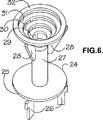
触媒従動器24の代替の形を図6および7に示す。これは適切な合金から鋳造する。この従動器は底部ディスク25を含み、このディスク25の下には3つのスペーサ要素26があるが、これらの要素は互いに対して120°に配置され、反応管T内を通る気体の上昇流がない場合に触媒従動器24をレッジ2で支えるのに役立つものである。スペーサ要素26間の隙間と、底部ディスク25の周りの環状の隙間は、上昇気体流量が閾値を超えたときに、遅い速度の気体を触媒従動器24の周りで上向きに流動させ、また触媒従動器24をレッジ2から持ち上げるのに役立つ。ディスク25の上方にはロッド部分27があり、その上端からは3つのステップ状フランジ28が突出しているが、これらのフランジは、ロッド部分27の軸を中心として、120°の角度で互いに対し半径方向に間隔を空けて配置されている。フランジ28には、一連のリング29、30、31、および32が固定されており、隣接するリング同士の間隔は、損傷を受けていない触媒粒子の最小寸法よりも小さい。このように触媒粒子は、触媒従動器24の下まで管内を通過することができないのに対し、気体またはその他の弾性流体は、触媒従動器24をレッジ2から持ち上げる、閾値よりも下および上の流量で、管内を上昇することができる。
An alternative form of
改質管Tに内部レッジ2を設ける代わりに、このレッジ2を、いくつかの小さい内向きの突起、例えば3または4個の小さい突起に代えることが適切であり、これらの突起の間のスペースは、底部ディスク25を通過した弾性流体の上昇流の通路になる。この場合、プレート13またはスペーサ要素26を必要としない。あるいはレッジ2の代わりに、必要に応じて改質管Tの中身を下向きに空にすることができるように、中心垂直アパーチャと共に形成された取外し可能な支持器具を用いることができる。
次に、図1〜4の装置を使用した好ましいプロセスの操作について述べる。図5および6の装置は同様の方法で使用することができる。
Instead of providing an
The operation of the preferred process using the apparatus of FIGS. The apparatus of FIGS. 5 and 6 can be used in a similar manner.
管T内に触媒粒子を充填するため、任意の適切な方法を使用することができる。例えば、触媒が十分に堅固なものである場合は、上部穴あき保持器3を取り外し、次いでその触媒の所望の量が導入されるまで触媒Cを慎重に注入することができる。改質管Tの断面は比較的小さいので、触媒粒子は管Tの壁面に衝突し易く、したがって完全な自由落下は決して生じない。このため、触媒粒子が改質管Tを下降するとき、触媒粒子は管T内を自由落下するのではなくぶつかり合いながら下降していく。触媒が脆い性質のものである場合、ワイヤ、ワイヤコイル、または米国特許明細書第5,247,970号(Ryntveit他)の器具を使用した前述の技法のいずれかを使用することができる。あるいは、例えば「ソック(sock)」技法を使用することができる。 Any suitable method can be used to fill the catalyst particles into the tube T. For example, if the catalyst is sufficiently rigid, the top perforated cage 3 can be removed and then the catalyst C can be carefully injected until the desired amount of the catalyst has been introduced. Since the cross section of the reforming tube T is relatively small, the catalyst particles are likely to collide with the wall surface of the tube T, so that complete free fall never occurs. For this reason, when the catalyst particles descend the reforming tube T, the catalyst particles descend while colliding with each other instead of freely falling within the tube T. If the catalyst is of brittle nature, any of the techniques described above using wires, wire coils, or instruments of US Pat. No. 5,247,970 (Ryntveit et al.) Can be used. Alternatively, for example, a “sock” technique can be used.
触媒充填材料を充填した後、触媒の沈降体積を測定し、設計値と比較することができる。その沈降体積が設計値よりも大きくまたは小さい場合、必要に応じて触媒の一部を取り除き、または触媒をさらに充填することができる。さらに、例えば水蒸気改質プロセスを稼動させる前に、通常は、上部穴あき保持器3を取り付けて、窒素などの気体を、閾値速度を超えた速度で管T内を上昇させ、それによって、触媒および触媒従動器4を管T内で上昇させて、上部穴あき保持器3の直下に触媒粒子のクッションが形成されるようにすることが望ましい。この上昇流は、上部穴あき保持器3を通過するのに十分小さな粒径を持つ実質的に全ての「微」粒子を通過させて気体で吹き飛ばすのに十分な時間および速度で、維持することができる。この手順は、触媒従動器4および触媒が管内を落下するまで気体流を減少させ、次いで気体の流れを再び閾値速度を超えるまで増大させることによって、必要なだけ何回も繰り返すことができる。次いで触媒クッションを通過する上昇流または沈降した触媒層を通過する下降流において、触媒充填材料を通過する際の圧力低下を測定し、設計値と比較することができる。沈降体積または圧力低下が望ましくない場合、上部穴あき保持器3を取り外し、必要に応じて触媒をさらに追加しまたは触媒の一部を取り除くことができ、管T内の触媒の充填が満足のいくものであると見なされることを測定値が示すようになるまで、この手順を繰り返すことができる。
After filling the catalyst packing material, the sedimentation volume of the catalyst can be measured and compared with the design value. If the sedimentation volume is larger or smaller than the design value, part of the catalyst can be removed or further filled with catalyst as required. In addition, for example, prior to running the steam reforming process, typically an upper perforated cage 3 is installed to allow a gas such as nitrogen to rise in the tube T at a rate exceeding the threshold rate, thereby providing a catalyst. It is desirable to raise the
気体または蒸気は、上昇流量が低い状態で、沈降した触媒粒子C層内を流れる。しかし流量が増すにつれ、少なくとも一部の触媒粒子が浮揚し易くなり、触媒粒子Cの下部静止層の上方に、一部流動化した層を初めに形成する。流量が増すにつれてますます多くの触媒粒子Cが流動化し、改質管T内を上方に移動して、上部穴あき保持器3の下面に接するように触媒粒子Cクッションを形成する。この手順の間、全ての塵またはサイズの小さい粒子は、上部穴あき保持器3内を通過し易くなる。流量がさらに増すと、実質上全ての触媒粒子Cが触媒従動器4の最上部から浮揚して触媒粒子Cのクッションに入り、比較的少ない数の粒子が触媒粒子Cのクッションの下で動いている状態になるが、これら動いている粒子は重力下で落下し、次いで再び上昇する気体または蒸気によって持ち上げられる。最終的に、流量がさらに増すにつれ、触媒従動器4は図3に示すように、触媒粒子クッションの下面に突き当たるまで上向きに移動し、それによって、触媒粒子のさらなる運動、すなわち可能性ある触媒粒子の摩耗を防止する。
The gas or vapor flows in the sedimented catalyst particle C layer with a low ascending flow rate. However, as the flow rate increases, at least some of the catalyst particles become more likely to float, and a partially fluidized layer is first formed above the lower stationary layer of catalyst particles C. As the flow rate increases, more and more catalyst particles C fluidize and move upward in the reforming tube T to form a catalyst particle C cushion so as to contact the lower surface of the upper perforated cage 3. During this procedure, all dust or small particles are likely to pass through the upper perforated cage 3. When the flow rate is further increased, substantially all of the catalyst particles C float from the top of the
この手順の間、上方に流動する気体は、不活性ガス、例えば窒素または空気である。水蒸気改質触媒のクッションの形成は大気圧よりも少し高い圧力で達成できる。しかしながら、その後、好ましくは管Tの圧力を水蒸気改質に効果的な圧力、例えば約100psi〜約600psi(約698.48kPa〜約4136.86kPa)の圧力まで高められる。その後、バーナーBは点火を開始するために天然ガスを用いて点火でき、その後全てのバーナーBが点火された後、水素リッチな燃料に切り替える。管Tが適当な温度、例えば約500℃またはそれ以上、好ましくは少なくとも約750℃から約1050℃まで、に達したら、不活性ガス供給は水蒸気改質される水蒸気と炭化水素原料、例えば天然ガスの混合物に切り替えられる。 During this procedure, the upward flowing gas is an inert gas such as nitrogen or air. Formation of the steam reforming catalyst cushion can be achieved at a pressure slightly above atmospheric pressure. However, preferably, the pressure in tube T is then increased to a pressure effective for steam reforming, such as a pressure of about 100 psi to about 600 psi (about 698.48 kPa to about 4136.86 kPa). The burner B can then be ignited using natural gas to initiate ignition, after which all burners B are ignited before switching to hydrogen rich fuel. When the tube T reaches a suitable temperature, for example about 500 ° C. or higher, preferably at least about 750 ° C. to about 1050 ° C., the inert gas feed is steam reformed with steam and hydrocarbon feed, eg natural gas. To a mixture of
高温動作温度に加熱する過程で、改質管Tは半径方向および長手方向に膨張し、拡がったスペースに低膨張率の触媒が移動してそのスペースを埋めることになる。しかしながら、触媒粒子のクッションの最上部の位置は、いつでも固定されており、一方、このクッションの底部はわずかに上向きに移動する。この触媒のクッションの最上部の位置の固定、すなわち動作中の触媒層の最上部の位置の固定は、触媒に対して精密に熱の導入を位置付ける必要がある頂上加熱(top-fired)水蒸気改質炉において非常に有利なものである。さらに、触媒充填管の内部または外部の温度制御が不十分であることによる管の故障という問題を、実質的に未然に防ぐという追加の利点もある。よって、触媒層の上部表面の位置が上部穴あき保持器3の位置によって固定され、そしてその位置はバーナーBの関係によって正確に知られるので、管Tの内部表面に隣接した触媒の欠如による吸熱水蒸気改質反応の管Tの内部表面を冷却しないことの結果としての、過熱状態となる触媒を含んでいない、バーナーBに隣接した改質管の部分の危険は実質的にない。 In the process of heating to a high operating temperature, the reforming tube T expands in the radial direction and the longitudinal direction, and the low expansion coefficient catalyst moves to fill the expanded space. However, the position of the top of the cushion of catalyst particles is always fixed, while the bottom of the cushion moves slightly upwards. This fixed top position of the catalyst cushion, i.e., the top position of the active catalyst layer, is a top-fired steam reformer that requires the precise introduction of heat to the catalyst. It is very advantageous in the quality furnace. In addition, there is an additional advantage that the problem of tube failure due to insufficient temperature control inside or outside the catalyst packed tube is substantially obviated. Thus, the position of the upper surface of the catalyst layer is fixed by the position of the upper perforated cage 3, and the position is accurately known by the relationship of the burner B, so the endotherm due to the lack of catalyst adjacent to the inner surface of the tube T. There is virtually no risk of the portion of the reforming tube adjacent to the burner B that does not contain a catalyst that becomes overheated as a result of not cooling the internal surface of the tube T of the steam reforming reaction.
一連の操作の終わりの時点で、反応管Tを通って水蒸気と天然ガスの流れを維持し、管Tと炉Fが冷えるようにバーナーを消すことができる。次いで、圧力を待機時または停止時の圧力条件に戻す前または戻す後に、供給材料を不活性ガスまたは空気に切り換えることができる。次いで、窒素または空気の流量を減少でき、それで触媒従動器4または24および触媒粒子Cは、触媒従動器4または24が再びレッジ2(または改質管Tの内容物を下方に向けて一掃できるよう、上述のようにレッジ2を取り外し可能な支持器具に代えた場合には取り外し可能な支持器具)で支えられるようになるまで、かつ触媒粒子が受ける損傷を最小限に抑えた状態でその触媒粒子が図2に示す状態に静かに戻るまで、制御された手法でもとの位置に下降する。
At the end of the series of operations, the steam and natural gas flows through the reaction tube T can be maintained and the burner can be turned off so that the tube T and the furnace F cool. The feed can then be switched to an inert gas or air before or after returning the pressure to standby or stop pressure conditions. The flow rate of nitrogen or air can then be reduced so that the
上昇流モードを再び開始する際、触媒は部分的にリミックスされている。触媒粒子は、全ての管Tにおいて一貫して低い充填密度を改め、一方、微粉および破片を、気体の上昇流によって除去することになる。したがって各管Tの両端間での圧力低下は、触媒の寿命期間中、実質的に一定のままになる。 When starting upflow mode again, the catalyst is partially remixed. The catalyst particles will consistently modify the low packing density in all tubes T, while fines and debris will be removed by the upward flow of gas. Thus, the pressure drop across each tube T remains substantially constant over the life of the catalyst.
上昇流モードにおける一連の操作の終わりの冷却操作中、気体流を1回または複数回増大させて、上部穴あき保持器3の下面に接するように触媒粒子のクッションを再び生成することができ、その後、改質管Tの冷却中に触媒粒子のいかなる「ブリッジ」も形成されないように、気体流を再び減少させることができるが、そのようにしないと、冷却したときの改質管Tの収縮壁面によって、触媒粒子に破砕力が加えられるという危険性が生じるからである。 During the cooling operation at the end of the series of operations in the upflow mode, the gas flow can be increased one or more times to regenerate the cushion of catalyst particles so as to contact the lower surface of the upper perforated cage 3, Thereafter, the gas flow can be reduced again so that no “bridges” of catalyst particles are formed during the cooling of the reforming tube T; otherwise, the shrinkage of the reforming tube T when cooled. This is because the wall surface creates a danger that a crushing force is applied to the catalyst particles.
バーナーBへの燃料の供給速度を低下させることで、改質管を少し冷却するようにし、次いで各管7の触媒粒子Cおよび触媒従動器4を下降させるために水蒸気と天然ガスの流れを減少させて一連の操作を中断することが可能である。触媒粒子Cのクッションが生じるような値に改め、各管7における触媒従動器4が上がるように水蒸気と天然ガスの流れを戻すことができる。触媒粒子のクッションを改める際に、いかなる塵や触媒の破片は上部穴あき触媒保持器3内を通過し易くなり、したがって、触媒クッションの両端間における圧力低下の望ましくない増大の、可能性ある原因が取り除かれる。その後、一連の操作を続けるようにバーナーBへの燃料の供給を再び増加させることができる。
By reducing the fuel supply rate to the burner B, the reforming pipes are cooled slightly, and then the flow of steam and natural gas is reduced to lower the catalyst particles C and the
改質炉中の各触媒管の両端での圧力低下が他の各々の管T対応する圧力低下に実質的に同じであるように各々の水蒸気改質管Tに触媒を正確に同じように充填することが望ましいので、管Tは上記一般的方法によって充填される。この場合、粒状触媒物質の落下速度を小さくするために、窒素や空気のようなガスの上昇流が使用できる。この空気流は、全ての他の管Tの上端を栓をすることによって、マニホールドから流せるように管Tに単独で適用するか、または順番に対応するピグテイルPを一時的に離した後、各改質管Tの底から適用できる。後の選択が好ましい。なぜなら、他の管が充填されている間に、充填されている管についてほかの操作を行なうことができるからである。
Each steam reformer tube T is filled with catalyst exactly the same so that the pressure drop across each catalyst tube in the reformer is substantially the same as the corresponding pressure drop for each other tube T. The tube T is filled by the general method described above. In this case, an upward flow of gas such as nitrogen or air can be used to reduce the falling speed of the particulate catalyst material. This air flow can be applied to the tube T alone so that it can flow out of the manifold by plugging the tops of all other tubes T, or the pigtails P corresponding to the sequence can be temporarily released before each It can be applied from the bottom of the reforming tube T. Subsequent selection is preferred. This is because, while the other tube is filled, is because it is a child that is responsible for other operations for the tube being filled.
炉FはバーナーBの下方燃焼(downfiring)を用いることによる多くの利益を有する。シェルS内で火は下向きに向いているので、燃焼ガスは、対応する上部支持部または上方向燃焼(upfired)の炉デザインの管の支持と比べて、比較的冷たいままでいる上部支持部Uには突き当たらない。同様に、上記バーナーBの全ての構造は、最大の燃焼温度の十分下の温度に保たれる。これは管Tの束の全重量を上部支持部Uによって支えることができ、かつ改質管Tの下端の支持に必要な分離された支持体が無いことを意味する。これはまた、改質管7が各々広がりそして他の改質管Tが縦方向に独立に縮むことができることをも意味する。もし保守の目的で改質管Tの束を動かしたいときは、その時は改質管Tの底からピグテイルPを外した後、管Tの全束をバーナーB、熱交換部H及びヘッダーHと一緒に、独立にまたは一緒にシェルSの外に持ち上げることができる。
Furnace F has many benefits from using downfiring of burner B. Since the fire is directed downwards in the shell S, the combustion gases remain relatively cool compared to the corresponding upper support or upfired furnace design tube support U. It doesn't hit. Similarly, all the structures of the burner B are kept at a temperature well below the maximum combustion temperature. This means that the entire weight of the bundle of tubes T can be supported by the upper support U and there is no separate support necessary to support the lower end of the reforming tube T. This also means that the reforming
各管T中の触媒のチャ−ジに関しては、層を通じての低圧力低下を好ましく維持するために、触媒粒子Cのクッションは緩く詰められる。さらに、いかなる“微粒子”の触媒粒子も、上昇流によって、上部保持器3を通って触媒粒子Cのクッションから上方向に持ち去られるであろう。それ故、これ等の個々の改質管T中の触媒のチャ−ジの両端で圧力低下を引き起こす“微粒子”の触媒粒子は、触媒のチャ−ジ中には残らないであろう。結果として、各改質管Tの両端での圧力低下は触媒チャ−ジの寿命を通じて、実質的に一定に保たれるか、または比較的小さな変化しか起きないであろう。このように、各改質管の両端の圧力低下は、何時も、別の改質管Tの各々の両端の圧力低下と実質的に同様に維持することができる。 With respect to the charge of the catalyst in each tube T, the cushion of catalyst particles C is loosely packed in order to favorably maintain a low pressure drop through the bed. Furthermore, any “fine particle” catalyst particles will be lifted away from the cushion of catalyst particles C through the upper cage 3 by upward flow. Therefore, "fine particulate" catalyst particles that cause a pressure drop across the catalyst charge in these individual reforming tubes T will not remain in the catalyst charge. As a result, the pressure drop across each reformer tube T will remain substantially constant throughout the life of the catalyst charge, or only relatively small changes will occur. Thus, the pressure drop across each reformer tube can be maintained at substantially the same time as the pressure drop across each reformer tube T.
下部方向に向いた炎を用いることの他の利点は、炉B用の燃料とそのための燃焼空気が、熱い改質ガスによって加熱され、その水平断面の大きさが炉のシェルのそれより大きくてもよい、比較的大きな熱交換部分Hが改質管Tの上部に位置しており、それで炉シェルSの頂上から容易に上に取り外すことができることである。 Another advantage of using a downward-facing flame is that the fuel for furnace B and the combustion air therefor are heated by hot reformed gas, and that the horizontal cross-section is larger than that of the furnace shell. A relatively large heat exchanging part H is located at the top of the reforming tube T, so that it can be easily removed from the top of the furnace shell S.
本発明をさらに、以下の実施例を用いて示す。 The invention is further illustrated by the following examples.
実施例1
図1〜4中に例示されたタイプの、従動器4を最初に底端に位置させた、長さ2m、内部直径38.1mmのガラスチューブ1を垂直に設置した。この従動器4は直径36mmのディスク12を持っていた。1.84kgのニッケル触媒のチャ−ジ(公称直径6mmのカルシアーアルミナ担体触媒ボ−ル上の12%ニッケル)を注意深くチューブ中に落とし込んだ。充填後、上部に孔のあいた触媒保持装置3をチューブ1中の所望の高さに嵌めこんだ。この保持装置は2mmのギャップを有する1.5mmのワィヤーを含むジョンソンウエッジ−ワイヤースクリーンよりなっていた。テスト期間中の触媒のより低い嵩比重を考慮に入れて、チューブ1は満杯には詰められていなかった。圧縮空気を、調圧装置と流量計(図示されていない)を経由して、少なくとも触媒を持ち上げるのに十分な速度で、また触媒従動器4がチューブ1の頂部において保持装置3の直下に触媒ボール(balls)5の強固なクッションが形成されるように、チューブ1の底部に導入した。触媒床5の高さは空気の導入前に測定された。次いで、従動器4がチューブ1の底部に降下されるように、また同様に触媒ボ−ルがチューブ1の底部に降下されるように、空気流量が低下された。この操作は多数回繰り返されて、そのデーターから下記の平均見かけ嵩比重がkg/cm3で決定された。密度は360回のテストを通じて、下記のように小さな変動を伴う非常に再現性の良いものであることがわかった。(その360回のテストの間、10、20及び120回のテスト後に、触媒はチュ−ブから取り出され、そして再充填された。):
充填後(自由落下) 1157 +/− 1.0%(4回の充填を通じて)
持ち上げ時(空気流により)1017 +/− 0.5%(どれか1充填範囲内)
持ち上げ時(空気流により)1017 +/− 1.5%(全体のテストを通じ)
降下時(空気流を伴わず) 1000 +/− 0.5%(どれか1充填範囲内)
降下時(空気流を伴わず) 1000 +/− 1.0%(全体のテストを通じ)
実施例2
実施例1において10、20、120および360回のテスト後の触媒の重量をチェックしたところ、360回のテストを通じて0.38質量%の損失を示した。同じ装置を用いての別の試験において、新しい触媒粒子および実施例1で使用済みの触媒粒子の耐流動性を比較した。空気流速が49.14Nm3/hにおいて新しい触媒粒子の圧力低下は1.21×105Pa/mであり、一方、空気流速が48.96Nm3/hにおいて360回テスト後の使用済み触媒粒子の耐流動性は1.22×105Pa/mであった。
Example 1
1-4, a glass tube 1 having a length of 2 m and an internal diameter of 38.1 mm was installed vertically, with the
After filling (free fall) 1157 +/- 1.0% (through 4 fillings)
When lifted (by airflow) 1017 +/- 0.5% (within one filling range)
When lifted (by airflow) 1017 +/- 1.5% (through overall testing)
When descending (without air flow) 1000 +/- 0.5% (within one filling range)
When descending (without air flow) 1000 +/- 1.0% (through overall testing)
Example 2
In Example 1, the weight of the catalyst after 10, 20, 120, and 360 tests was checked, and showed a loss of 0.38% by mass through 360 tests. In another test using the same apparatus, the flow resistance of the new catalyst particles and the catalyst particles used in Example 1 were compared. The pressure drop of the fresh catalyst particles air flow velocity in 49.14Nm 3 / h is 1.21 × 10 5 Pa / m, whereas, spent catalyst particles after test 360 times the air flow velocity in 48.96Nm 3 / h The flow resistance of was 1.22 × 10 5 Pa / m.
実施例3
2.06kgのDycat製、タイプ54/98、公称直径6mmのα−アルミナ上に担持されたニッケル触媒ボ−ルを用いて実施例1の手順を続けた。この触媒担体物質は実施例1と2で用いたものより破砕しやすく、実施例1と2で用いた触媒の破砕強度の約25%しかない。10、60、150、300および390回のテストの後、触媒の重量をチェックしたところ、390回のテストを通じて全質量損失は7.0%を示した。試験の間にこの質量損失で表された触媒の破片は、ガス流によってベッドから塵として明らかに除かれた。テストの各群における減少量は下記のように減少し、持ち上げ時及び降下時のサイクルあたりの平均質量%で表すと:0.085、0.042、0.026、0.010、0.009となった。
Example 3
The procedure of Example 1 was continued with a nickel catalyst ball supported on 2.06 kg of Dycat, Type 54/98, nominally 6 mm diameter α-alumina. This catalyst support material is easier to crush than those used in Examples 1 and 2, and is only about 25% of the crushing strength of the catalysts used in Examples 1 and 2. After 10, 60, 150, 300 and 390 tests, the weight of the catalyst was checked and the total mass loss was 7.0% throughout the 390 tests. The catalyst debris represented by this mass loss during the test was clearly removed as dust from the bed by the gas stream. The amount of reduction in each group of tests decreases as follows, expressed as the average mass% per cycle during lifting and lowering: 0.085, 0.042, 0.026, 0.010, 0.009. It became.
実施例4
実施例1〜3で用いたのと同じ装置を用いた別の実験で、新しい触媒粒子と390回のテスト後における使用済みの触媒粒子の耐流動性を比較した。空気流速が49.67Nm3/hにおいて新しい触媒粒子の圧力損失は1.15×105Pa/mであり、一方、空気流速が49.77Nm3/hにおいて使用済み触媒粒子の圧力損失は1.32×105Pa/mであった。圧力損失のこの増加は、主に空隙量の減少(新:0.462、使用済み:0.449と測定された)及び使用済み粒子のサイズの減少(それは、新しい触媒粒子と比べて2%の直径の減少に等しいと評価された。)に主に基くと帰することができる。この実施例は、プロセスは実質的に、粒子磨耗に基く微粒子は除かれるので、プロセスの運転中の圧力低下は実質的に期待されるほどに低く留まっていることを許容するものだと証明している。
Example 4
In another experiment using the same equipment used in Examples 1-3, the flow resistance of the new catalyst particles and the spent catalyst particles after 390 tests was compared. The pressure loss of the fresh catalyst particles air flow velocity in 49.67Nm 3 / h is 1.15 × 10 5 Pa / m, whereas, the pressure loss of the spent catalyst particles air flow velocity in 49.77Nm 3 / h 1 It was 32 × 10 5 Pa / m. This increase in pressure loss is primarily due to a decrease in void volume (new: 0.462, used: measured as 0.449) and a decrease in used particle size (which is 2% compared to new catalyst particles). It was estimated to be equal to a decrease in the diameter of. This example demonstrates that the process substantially eliminates particulate wear-based particulates, so that the pressure drop during operation of the process remains substantially as low as expected. ing.
Claims (34)
(a)複数の垂直な改質管(T)を含む水蒸気改質炉(F)を用意するステップ、
ただし各改質管(T)は、その下端には反応混合物供給マニフォールド(M)に接続した原料入り口(P)を有し、その上端には改質されたガス排出ヘッダー(R)に接続した出口を有しており、また、その上端と下端の間に配置された触媒収容ゾーンであって、触媒収容ゾーンを完全には満たしていない粒状水蒸気改質触媒(C)のチャージ(charge)を含む触媒収容ゾーンを有する、
(b)気体は通すが粒状水蒸気改質触媒(C)の粒子は触媒収容ゾーン内に保持されるよう適合された、触媒収容ゾーンの上端に取り付けられた上部保持手段(3)と、
或る閾値となる速度を超えた速度で触媒収容ゾーンを通過する気体の上昇流によって触媒収容ゾーンの下端から上向きに移動するための、粒状水蒸気改質触媒(C)のチャージの下に触媒収容ゾーン内に移動可能に取り付けられた従動手段(4;24)と
を用意するステップ、
(c)反応混合物の供給マニホールド(M)に炭化水素原料と水蒸気を含む反応混合物を、該反応混合物が各改質管(T)を通って上方に流れを生じるのに十分な速度で、該粒状水蒸気改質触媒(C)に各改質管(T)中をその上端に向かって上昇を起こさせ、そしてそれぞれの改質管(T)における上部保持手段(3)の下面に対して粒状水蒸気改質触媒(C)のクッションを形成させるのに十分な、そして、該それぞれの改質管(T)中の従動手段(4;24)が該それぞれの改質管(T)中の粒状水蒸気改質触媒(C)のクッションの下面に対して突き当たるまで上向きに移動するよう、前記閾値を越えた流速で供給するステップ、
(d)各々の複数の改質管(T)中で水蒸気改質条件が維持されるように水蒸気改質炉(F)で外部から各々の複数の改質管(T)を加熱して、炭化水素原料を水蒸気との反応により変換させて、酸化炭素類と水素よりなる改質ガス混合物を形成するステップ、
(e)改質ガス出口ヘッダー(R)から、得られた改質ガス混合物を回収するステップ。A steam reforming process in which a hydrocarbon feedstock is steam reformed by reacting with steam in the presence of a steam reforming catalyst under steam reforming conditions to produce a reformed gas mixture containing carbon oxides and hydrogen. The process includes the following steps:
(A) step of a plurality of vertical reforming tube (T) is prepared including steam reforming furnace (F),
However, each reforming tube (T) has a raw material inlet (P) connected to the reaction mixture supply manifold (M) at its lower end , and connected to a reformed gas discharge header (R) at its upper end. has an outlet also provides a catalyst containing zone disposed between its upper and lower ends, the charge of particulate steam reforming catalyst not fully meet the catalyst containing zone (C) a (charge) that having a catalyst containing zone, including,
(B) an upper holding means (3) attached to the upper end of the catalyst containing zone, adapted to hold gas but allow particulates of the steam reforming catalyst (C) to be held in the catalyst containing zone;
Certain threshold to become a gas passing through the catalyst containing zone at a rate exceeding the rate to move upward from the lower end of the catalyst containing zone by upflow, catalysts housed under the charge of particulate steam reforming catalyst (C) Providing follower means (4; 24) movably mounted in the zone ;
(C) supplying a reaction mixture comprising hydrocarbon feedstock and steam to the reaction mixture supply manifold (M) at a rate sufficient to cause the reaction mixture to flow upwardly through each reforming tube (T). The granular steam reforming catalyst (C) is caused to rise in the respective reforming tubes (T) toward the upper end thereof, and is granular with respect to the lower surface of the upper holding means (3) in each reforming tube (T). sufficient to form a cushion of steam reforming catalyst (C), element, each said reformer tubes (T) in the driven means (4; 24) of each said reformer tubes (T) in the Supplying at a flow rate exceeding the threshold so as to move upward until it comes into contact with the lower surface of the cushion of the granular steam reforming catalyst (C);
(D) heating each of the plurality of reforming tubes (T) from the outside in a steam reforming furnace (F) so that the steam reforming conditions are maintained in each of the plurality of reforming tubes (T); Converting a hydrocarbon feedstock by reaction with water vapor to form a reformed gas mixture comprising carbon oxides and hydrogen;
(E) recovering the obtained reformed gas mixture from the reformed gas outlet header (R).
(a)炉室(S);
(b)炉室(S)中には複数の垂直な改質管(T)があって、各改質管(T)は下端に反応混合物供給マニホールド(M)に繋がる原料の入り口(P)と、上端に改質ガス出口ヘッダー(R)に繋がる出口があり、上端と下端の中間に位置する触媒収容ゾーンを有しており、触媒収容ゾーンは触媒収容ゾーンを完全に満たすには不十分な量の粒状水蒸気改質触媒(C)のチャ−ジ(charge)を含んでいる;
(c)その複数の改質管(T)を外部から加熱するための炉室(S)中のバーナー手段(B)であって、これはその複数の改質管(T)の各々における水蒸気改質条件を維持し、炭化水素原料を蒸気と反応させて酸化炭素類と水素を含む改質ガス混合物に変換するためのものである;
(d)その複数の改質管(T)の各々の触媒収容ゾーンの上端に取り付けられた上部保持手段(3)であって、これは気体は通過できるが触媒収容ゾーン中の粒状水蒸気改質触媒(C)の粒子を保持するように適合されているものである;
(e)或る閾値となる速度を超えた速度で触媒収容ゾーンを通過する気体の上昇流によって触媒収容ゾーンの下端から上向きに移動するための、粒状水蒸気改質触媒(C)のチャ−ジ(charge)の下に触媒収容ゾーン内に移動可能に取り付けられた従動手段(4;24);
(f)各改質管(T)中で粒状水蒸気改質触媒(C)をその上端に向かって上昇させるのに十分であって、それぞれの改質管(T)中の上部保持手段(3)の下面に対して粒状水蒸気改質触媒(C)の粒子のクッションを形成するような流速で、かつそれぞれの改質管(T)中の従動手段(4;24)がそれぞれの改質管(T)中の粒状水蒸気改質触媒(C)のクッションの下面に対して突き当たるまで上向きに移動させるよう、閾値を超えた流速で、各改質管(T)を通って反応混合物を上方に流れさせるのに十分な流速で、反応混合物供給マニホルド(M)に炭化水素原料と水蒸気を含む反応混合物を供給するための手段、
(g)改質ガス出口ヘッダー(R)から得られた改質ガス混合物を回収するための手段(R)。Steam reforming for steam reforming of hydrocarbon feedstock that reacts with steam in the presence of steam reforming catalyst (C) to produce a reformed gas mixture containing carbon oxides and hydrogen under steam reforming conditions Furnace (F), which includes :
(A) furnace chamber (S);
(B) furnace chamber in (S) be a plurality of vertical reforming tube (T) is, the reformer tubes (T) is the raw material leads to the reaction mixture feed manifold to the lower end (M) inlet (P ) And an outlet connected to the reformed gas outlet header (R) at the upper end, and has a catalyst containing zone located between the upper end and the lower end, and the catalyst containing zone is not sufficient to completely fill the catalyst containing zone. Contains a sufficient amount of particulate steam reforming catalyst (C) charge;
(C) Burner means (B) in the furnace chamber (S) for heating the plurality of reforming tubes (T) from the outside, which is water vapor in each of the plurality of reforming tubes (T). Maintaining reforming conditions and reacting a hydrocarbon feed with steam to convert to a reformed gas mixture containing carbon oxides and hydrogen;
(D) Upper holding means (3) attached to the upper end of each catalyst containing zone of the plurality of reforming tubes (T), which is capable of passing gas but is granular steam reforming in the catalyst containing zone Are adapted to retain particles of catalyst (C);
(E) certain threshold to become the speed at a rate in excess of the gas passing through the catalyst containing zone to move upward from the lower end of the catalyst containing zone by upflow, tea particulate steam reforming catalyst (C) - di Follower means (4; 24) movably mounted in the catalyst receiving zone under the (charge );
A sufficient (f) each reforming tube (T) particulate steam reforming catalyst (C) in the raise towards its upper end, the upper retaining means of each reforming tube (T) (3 ) With a flow rate that forms a cushion of particles of the granular steam reforming catalyst (C) with respect to the lower surface of each of the reforming tubes (T), and the driven means (4; 24) in each reforming tube (T). The reaction mixture is passed upward through each reforming tube (T) at a flow rate exceeding the threshold so as to move upward until it strikes the lower surface of the cushion of the granular steam reforming catalyst (C) in (T). Means for supplying a reaction mixture comprising a hydrocarbon feedstock and water vapor to the reaction mixture supply manifold (M) at a flow rate sufficient to cause flow;
(G) Means (R) for recovering the reformed gas mixture obtained from the reformed gas outlet header (R).
Applications Claiming Priority (2)
| Application Number | Priority Date | Filing Date | Title |
|---|---|---|---|
| GBGB0113788.4A GB0113788D0 (en) | 2001-06-06 | 2001-06-06 | Furnace and process |
| PCT/GB2002/002549 WO2002098789A1 (en) | 2001-06-06 | 2002-06-05 | Furnace and steam reforming process |
Publications (2)
| Publication Number | Publication Date |
|---|---|
| JP2005507842A JP2005507842A (en) | 2005-03-24 |
| JP4256255B2 true JP4256255B2 (en) | 2009-04-22 |
Family
ID=9916037
Family Applications (1)
| Application Number | Title | Priority Date | Filing Date |
|---|---|---|---|
| JP2003501789A Expired - Fee Related JP4256255B2 (en) | 2001-06-06 | 2002-06-05 | Furnace and steam reforming process |
Country Status (17)
| Country | Link |
|---|---|
| US (1) | US7067107B2 (en) |
| EP (1) | EP1392598B1 (en) |
| JP (1) | JP4256255B2 (en) |
| CN (1) | CN100413573C (en) |
| AP (1) | AP1608A (en) |
| AR (1) | AR034076A1 (en) |
| AU (1) | AU2002310608B2 (en) |
| BR (1) | BR0210192B1 (en) |
| CA (1) | CA2449695C (en) |
| CO (1) | CO5540336A2 (en) |
| DE (1) | DE60220274T2 (en) |
| EA (1) | EA005713B1 (en) |
| GB (1) | GB0113788D0 (en) |
| NO (1) | NO331528B1 (en) |
| OA (1) | OA12614A (en) |
| WO (1) | WO2002098789A1 (en) |
| ZA (1) | ZA200308909B (en) |
Families Citing this family (11)
| Publication number | Priority date | Publication date | Assignee | Title |
|---|---|---|---|---|
| PL2444766T3 (en) * | 2003-07-15 | 2014-09-30 | Ngk Insulators Ltd | Firing furnace and method for firing |
| US20080286159A1 (en) * | 2006-09-15 | 2008-11-20 | Grover Bhadra S | Variable Tube Diameter For SMR |
| FR2918656B1 (en) * | 2007-07-12 | 2009-10-09 | Air Liquide | METHOD OF CONTROLLING THE FLOW OF COMBUSTIBLE GAS DURING THE STARTING PHASE OF A REFORMING OVEN. |
| MX357518B (en) * | 2012-04-03 | 2018-07-12 | Johnson Matthey Plc | Expanding centers for stackable structural reactors. |
| CN104211022A (en) * | 2014-08-22 | 2014-12-17 | 合肥四方磷复肥有限责任公司 | Rapid ignition method of boiling furnace |
| CN105478062B (en) * | 2015-12-14 | 2018-02-13 | 天津市天环精细化工研究所 | A kind of packing method of benzene method maleic anhydride catalyst |
| CN109996760B (en) * | 2016-10-25 | 2022-09-02 | 法国德西尼布 | Catalyst tube for reforming |
| CN107543421B (en) * | 2017-08-09 | 2019-12-03 | 中冶华天工程技术有限公司 | Produce the pusher-type furnace apparatus for vapour-cooling of superheated steam |
| US10562001B2 (en) | 2017-12-20 | 2020-02-18 | Uop Llc | Adjustable lift engager |
| GB201813431D0 (en) * | 2018-08-17 | 2018-10-03 | Weedon Geoffrey Gerald | Process & apparatus for steam reforming |
| US10478794B1 (en) * | 2019-02-26 | 2019-11-19 | Chevron Phillips Chemical Company Lp | Bi-modal radial flow reactor |
Family Cites Families (38)
| Publication number | Priority date | Publication date | Assignee | Title |
|---|---|---|---|---|
| US2203840A (en) * | 1939-07-12 | 1940-06-11 | Universal Oil Prod Co | Apparatus for retaining contact masses in tubular elements |
| NL112587C (en) * | 1958-05-29 | |||
| DE1063128B (en) * | 1958-06-07 | 1959-08-13 | Deggendorfer Werft Eisenbau | Closing device for contact tubes |
| DE1296127B (en) * | 1967-03-23 | 1969-05-29 | Rheinpreussen Ag | Device for closing reaction tubes |
| US3628314A (en) * | 1969-11-20 | 1971-12-21 | Phillips Petroleum Co | Packed-bed retainer |
| US3818667A (en) * | 1971-03-22 | 1974-06-25 | Universal Oil Prod Co | Louvered screen support member for particulate material |
| US3838977A (en) * | 1972-02-24 | 1974-10-01 | Ethyl Corp | Catalytic muffler |
| US4051019A (en) * | 1974-04-22 | 1977-09-27 | Uop Inc. | Method for loading finely divided particulate matter into a vessel |
| US3990858A (en) * | 1974-11-19 | 1976-11-09 | The Lummus Company | Device for retaining particulate material in upflow tubes |
| JPS523579A (en) * | 1975-06-27 | 1977-01-12 | Sumitomo Chem Co Ltd | Method of packing |
| JPS5243018A (en) * | 1975-10-03 | 1977-04-04 | Nissan Motor Co Ltd | Catalytic converter |
| JPS5534265Y2 (en) * | 1975-10-30 | 1980-08-14 | ||
| US4029486A (en) * | 1976-02-25 | 1977-06-14 | Graham-White Sales Corporation | Pneumatic compactor for particulate desiccant |
| CA1095696A (en) * | 1976-12-22 | 1981-02-17 | Richard F. Buswell | Catalytic reaction apparatus |
| CA1101194A (en) * | 1976-12-22 | 1981-05-19 | Richard F. Buswell | Multi-tube catalytic reaction apparatus |
| CA1103428A (en) * | 1976-12-22 | 1981-06-23 | George R. Krar | Compact multi-tube catalytic reaction apparatus |
| US4203950A (en) * | 1977-12-27 | 1980-05-20 | United Technologies Corporation | Steam reforming reactor designed to reduce catalyst crushing |
| US4292274A (en) * | 1980-08-04 | 1981-09-29 | United Technologies Corporation | Catalytic reactor with improved burner |
| US4336042A (en) * | 1980-10-14 | 1982-06-22 | Graham-White Sales Corporation | Canister-compactor assembly |
| US4430304A (en) * | 1981-11-13 | 1984-02-07 | The United States Of America As Represented By The United States Department Of Energy | Slab reformer |
| US4554784A (en) * | 1983-08-17 | 1985-11-26 | The Garrett Corporation | Emergency power unit and method |
| US4505105A (en) * | 1983-08-17 | 1985-03-19 | The Garrett Corporation | No-back gas generator and method |
| US4489549A (en) * | 1983-08-17 | 1984-12-25 | The Garrett Corporation | Gas generator with ratchet no-back and method |
| US5766555A (en) * | 1987-05-07 | 1998-06-16 | Grochowski; Horst | Feed inlet floor for mobile bed reactors |
| US4997465A (en) * | 1989-03-09 | 1991-03-05 | Vbm Corporation | Anti-fluidization system for molecular sieve beds |
| US5567398A (en) * | 1990-04-03 | 1996-10-22 | The Standard Oil Company | Endothermic reaction apparatus and method |
| GB9016415D0 (en) * | 1990-07-26 | 1990-09-12 | Boc Group Plc | Gas treatment or separation apparatus |
| JPH04119902A (en) * | 1990-09-10 | 1992-04-21 | Toshiba Corp | Method for operating fuel reformer |
| US5098453A (en) * | 1991-05-02 | 1992-03-24 | General Motors Corporation | Vapor storage canister with volume change compensator |
| NO175579B1 (en) * | 1991-12-20 | 1994-11-03 | Unidense Technology Gmbh | Method and apparatus for loading particulate material into vertical rudders |
| JPH0930801A (en) * | 1995-07-19 | 1997-02-04 | Mitsubishi Electric Corp | Reformation reactor |
| JP3476307B2 (en) * | 1996-05-09 | 2003-12-10 | 三菱レイヨン株式会社 | Method for filling catalyst for synthesis of unsaturated aldehyde and unsaturated carboxylic acid |
| US5718881A (en) * | 1996-06-24 | 1998-02-17 | International Fuel Cells, Inc. | Catalytic reactor designed to reduce catalyst slumping and crushing |
| JPH11139802A (en) * | 1997-11-04 | 1999-05-25 | Aisin Seiki Co Ltd | Reformer for fuel cell |
| US5877331A (en) * | 1997-11-12 | 1999-03-02 | Huntsman Petrochemical Corporation | Prevention of catalyst attrition and tar formation in manufacture of maleic anhydride |
| JP3169574B2 (en) | 1997-12-24 | 2001-05-28 | 日華化学株式会社 | Method for producing 4-hydroxy-4'-benzyloxydiphenyl sulfone |
| US6527980B1 (en) * | 2000-10-12 | 2003-03-04 | Air Products And Chemicals, Inc. | Reforming with intermediate reactant injection |
| US6793700B2 (en) * | 2002-01-14 | 2004-09-21 | Air Products And Chemicals, Inc. | Apparatus and method for production of synthesis gas using radiant and convective reforming |
-
2001
- 2001-06-06 GB GBGB0113788.4A patent/GB0113788D0/en not_active Ceased
-
2002
- 2002-06-03 AR ARP020102060A patent/AR034076A1/en not_active Application Discontinuation
- 2002-06-05 OA OA1200300311A patent/OA12614A/en unknown
- 2002-06-05 EP EP02735598A patent/EP1392598B1/en not_active Expired - Lifetime
- 2002-06-05 CN CNB028114272A patent/CN100413573C/en not_active Expired - Fee Related
- 2002-06-05 DE DE60220274T patent/DE60220274T2/en not_active Expired - Lifetime
- 2002-06-05 AP APAP/P/2003/002939A patent/AP1608A/en active
- 2002-06-05 AU AU2002310608A patent/AU2002310608B2/en not_active Ceased
- 2002-06-05 JP JP2003501789A patent/JP4256255B2/en not_active Expired - Fee Related
- 2002-06-05 WO PCT/GB2002/002549 patent/WO2002098789A1/en active IP Right Grant
- 2002-06-05 CA CA002449695A patent/CA2449695C/en not_active Expired - Fee Related
- 2002-06-05 EA EA200400003A patent/EA005713B1/en not_active IP Right Cessation
- 2002-06-05 US US10/479,908 patent/US7067107B2/en not_active Expired - Fee Related
- 2002-06-05 BR BRPI0210192-0A patent/BR0210192B1/en not_active IP Right Cessation
-
2003
- 2003-11-14 ZA ZA2003/08909A patent/ZA200308909B/en unknown
- 2003-11-24 CO CO03103529A patent/CO5540336A2/en active IP Right Grant
- 2003-12-04 NO NO20035396A patent/NO331528B1/en not_active IP Right Cessation
Also Published As
| Publication number | Publication date |
|---|---|
| CN100413573C (en) | 2008-08-27 |
| CO5540336A2 (en) | 2005-07-29 |
| GB0113788D0 (en) | 2001-07-25 |
| AP1608A (en) | 2006-05-04 |
| WO2002098789A1 (en) | 2002-12-12 |
| US7067107B2 (en) | 2006-06-27 |
| CA2449695A1 (en) | 2002-12-12 |
| EA200400003A1 (en) | 2004-04-29 |
| CN1514803A (en) | 2004-07-21 |
| ZA200308909B (en) | 2005-01-26 |
| BR0210192A (en) | 2004-07-27 |
| OA12614A (en) | 2006-06-12 |
| JP2005507842A (en) | 2005-03-24 |
| NO331528B1 (en) | 2012-01-23 |
| CA2449695C (en) | 2009-09-15 |
| DE60220274D1 (en) | 2007-07-05 |
| BR0210192B1 (en) | 2011-01-11 |
| AU2002310608B2 (en) | 2006-10-19 |
| AR034076A1 (en) | 2004-01-21 |
| DE60220274T2 (en) | 2007-08-30 |
| EP1392598B1 (en) | 2007-05-23 |
| AP2003002939A0 (en) | 2003-12-31 |
| EA005713B1 (en) | 2005-04-28 |
| EP1392598A1 (en) | 2004-03-03 |
| US20040136903A1 (en) | 2004-07-15 |
| NO20035396D0 (en) | 2003-12-04 |
Similar Documents
| Publication | Publication Date | Title |
|---|---|---|
| JP4256255B2 (en) | Furnace and steam reforming process | |
| JP2002529895A (en) | Hydrocarbon fuel gas reformer for fuel cell power equipment | |
| JP4177754B2 (en) | Method and apparatus for filling a vertical tube with particulate solid | |
| JP6226994B2 (en) | Steam reforming exchanger-a system using a removable helical element that densely charges the bayonet tube for the reactor | |
| AU2002310608A1 (en) | Furnace and steam reforming process | |
| JP6349317B2 (en) | Steam reforming exchanger-a system using a removable deflector that densely charges the bayonet tube for the reactor | |
| AU2002304515A1 (en) | Process and apparatus for loading a particulate solid into a vertical tube | |
| JP6248115B2 (en) | Steam reforming exchanger-a system using a flexible and removable deceleration element to densely load a bayonet tube for a reactor with a catalyst | |
| JP6341919B2 (en) | Steam reforming reactor-gas system using an auxiliary tube supplying solid particles for dense loading of catalyst into a bayonet tube for the exchanger | |
| EP3414000B1 (en) | Enhanced efficiency endothermic reactor for syngas production with flexible heat recovery to meet low export steam generation. | |
| JPH03182591A (en) | Method and device for producing aromatic hydrocarbon from aliphatic hydrocarbon charged material in reactor heated by particle fluid bed | |
| CN114222624A (en) | Method for preventing fluidization of a catalytic fixed bed in a tubular upflow reactor of a steam methane reformer | |
| WO2006045746A1 (en) | Process to prepare a mixture of carbon monoxide and hydrogen | |
| JPH04119901A (en) | Reforming tube and reformer |
Legal Events
| Date | Code | Title | Description |
|---|---|---|---|
| A621 | Written request for application examination |
Free format text: JAPANESE INTERMEDIATE CODE: A621 Effective date: 20050603 |
|
| A131 | Notification of reasons for refusal |
Free format text: JAPANESE INTERMEDIATE CODE: A131 Effective date: 20080806 |
|
| A601 | Written request for extension of time |
Free format text: JAPANESE INTERMEDIATE CODE: A601 Effective date: 20081106 |
|
| A602 | Written permission of extension of time |
Free format text: JAPANESE INTERMEDIATE CODE: A602 Effective date: 20081113 |
|
| A521 | Written amendment |
Free format text: JAPANESE INTERMEDIATE CODE: A523 Effective date: 20081201 |
|
| TRDD | Decision of grant or rejection written | ||
| A01 | Written decision to grant a patent or to grant a registration (utility model) |
Free format text: JAPANESE INTERMEDIATE CODE: A01 Effective date: 20090107 |
|
| A01 | Written decision to grant a patent or to grant a registration (utility model) |
Free format text: JAPANESE INTERMEDIATE CODE: A01 |
|
| A61 | First payment of annual fees (during grant procedure) |
Free format text: JAPANESE INTERMEDIATE CODE: A61 Effective date: 20090129 |
|
| FPAY | Renewal fee payment (event date is renewal date of database) |
Free format text: PAYMENT UNTIL: 20120206 Year of fee payment: 3 |
|
| R150 | Certificate of patent or registration of utility model |
Free format text: JAPANESE INTERMEDIATE CODE: R150 |
|
| FPAY | Renewal fee payment (event date is renewal date of database) |
Free format text: PAYMENT UNTIL: 20130206 Year of fee payment: 4 |
|
| FPAY | Renewal fee payment (event date is renewal date of database) |
Free format text: PAYMENT UNTIL: 20140206 Year of fee payment: 5 |
|
| R250 | Receipt of annual fees |
Free format text: JAPANESE INTERMEDIATE CODE: R250 |
|
| R250 | Receipt of annual fees |
Free format text: JAPANESE INTERMEDIATE CODE: R250 |
|
| R250 | Receipt of annual fees |
Free format text: JAPANESE INTERMEDIATE CODE: R250 |
|
| LAPS | Cancellation because of no payment of annual fees |