JP4253121B2 - Surgical biopsy device - Google Patents
Surgical biopsy device Download PDFInfo
- Publication number
- JP4253121B2 JP4253121B2 JP2000512457A JP2000512457A JP4253121B2 JP 4253121 B2 JP4253121 B2 JP 4253121B2 JP 2000512457 A JP2000512457 A JP 2000512457A JP 2000512457 A JP2000512457 A JP 2000512457A JP 4253121 B2 JP4253121 B2 JP 4253121B2
- Authority
- JP
- Japan
- Prior art keywords
- tissue
- tubular member
- elongate tubular
- biopsy device
- distal end
- Prior art date
- Legal status (The legal status is an assumption and is not a legal conclusion. Google has not performed a legal analysis and makes no representation as to the accuracy of the status listed.)
- Expired - Fee Related
Links
Images


Classifications
-
- A—HUMAN NECESSITIES
- A61—MEDICAL OR VETERINARY SCIENCE; HYGIENE
- A61B—DIAGNOSIS; SURGERY; IDENTIFICATION
- A61B10/00—Other methods or instruments for diagnosis, e.g. instruments for taking a cell sample, for biopsy, for vaccination diagnosis; Sex determination; Ovulation-period determination; Throat striking implements
- A61B10/02—Instruments for taking cell samples or for biopsy
- A61B10/0233—Pointed or sharp biopsy instruments
- A61B10/0266—Pointed or sharp biopsy instruments means for severing sample
- A61B10/0275—Pointed or sharp biopsy instruments means for severing sample with sample notch, e.g. on the side of inner stylet
-
- A—HUMAN NECESSITIES
- A61—MEDICAL OR VETERINARY SCIENCE; HYGIENE
- A61B—DIAGNOSIS; SURGERY; IDENTIFICATION
- A61B10/00—Other methods or instruments for diagnosis, e.g. instruments for taking a cell sample, for biopsy, for vaccination diagnosis; Sex determination; Ovulation-period determination; Throat striking implements
- A61B10/02—Instruments for taking cell samples or for biopsy
- A61B10/0233—Pointed or sharp biopsy instruments
- A61B10/0283—Pointed or sharp biopsy instruments with vacuum aspiration, e.g. caused by retractable plunger or by connected syringe
-
- A—HUMAN NECESSITIES
- A61—MEDICAL OR VETERINARY SCIENCE; HYGIENE
- A61B—DIAGNOSIS; SURGERY; IDENTIFICATION
- A61B10/00—Other methods or instruments for diagnosis, e.g. instruments for taking a cell sample, for biopsy, for vaccination diagnosis; Sex determination; Ovulation-period determination; Throat striking implements
- A61B10/02—Instruments for taking cell samples or for biopsy
- A61B2010/0208—Biopsy devices with actuators, e.g. with triggered spring mechanisms
Landscapes
- Health & Medical Sciences (AREA)
- Life Sciences & Earth Sciences (AREA)
- Medical Informatics (AREA)
- Engineering & Computer Science (AREA)
- Biomedical Technology (AREA)
- Heart & Thoracic Surgery (AREA)
- Pathology (AREA)
- Molecular Biology (AREA)
- Surgery (AREA)
- Animal Behavior & Ethology (AREA)
- General Health & Medical Sciences (AREA)
- Public Health (AREA)
- Veterinary Medicine (AREA)
- Surgical Instruments (AREA)
- Sampling And Sample Adjustment (AREA)
Description
【0001】
【技術分野】
本開示は組織標本の生検装置に関し、特に、単挿入、多サンプル経皮的生検装置に関する。
【0002】
【関連技術の背景】
癌腫瘍、前悪性状態及びその他の病気を有することを疑われた患者を診断し且つ治療するために、組織をサンプル採取することがしばしば必要である。典型的には、疑われた癌組織の場合には、外科医が、触診、X−線又は超音波画像のような処置によって、疑わしい状態が存在することを確立するとき、細胞が癌である華道家を決定するために生検が行われる。生検は開放又は経皮的技術によってなされる。開放生検は全体の塊(切除生検)又は塊の一部(切開生検)を取る。他方、経皮的生検は通常は、針状器具でなされ、細い針吸引(fine needle aspiration (FNA))かコア生検のいずれかである。細い針吸引生検では、個々の細胞又は細胞のクラスターが細胞検査のために得られ、そして例えばパパニコラウ スミアで準備される。コア生検では、用語が示唆するように、コア又は断片組織が組織検査のために得られ、組織検査は凍結断面又はパラフィン断面を介してなされる。もっと最近の開発では、初期の処置の間に全体の塊を取るのに経皮的技術が使用されてきた。
【0003】
利用される生検のタイプは大部分が患者について現れる状況で決まり、あらゆる場合について単一の処置が理想的ではない。しかしながら、コア生検は多数の状態に極めて有用であり、大変しばしば使用されている。
患者の状態に関する明確な診断に到達するために器官又は病巣からの完全な組織が医療職員によって好まれる。ほとんどの場合には、器官又は病巣の一部だけをサンプル採取すればよい。摘出した組織の部分は全体として器官又は病巣を表わす。過去には、身体内の器官又は病巣から適当な組織を得るために、組織を確実に探し、特定し、且つ取るように手術が行われた。現在の技術では、定位のX-線、蛍光透視法、コンピュータ断層撮影法、超音波、核医学、及び磁気共鳴画像のような医療画像装置が使用される。これらの技術は身体の中の深い小さな以上を特定することを可能にする。しかしながら、明確な組織特性指摘は器官又は病巣の組織を特徴付けるのに適切な組織サンプルを得ることを依然として要求する。
【0004】
乳房撮影は、乳房異常を物理的な検査で診断することができるよりも早く触知できない(指診によって認知できない)乳房異常を特定することができる。ほとんどの触知可能な乳房異常は良性であるが、いくらかは悪性である。乳癌が触知できるようになる前にこれを診断するときには、乳癌の死亡率を減少させることができる。前触知可能な乳房異常が悪性かどうかを決定することは依然として困難である。と言うのは、いくらかの良性の病巣が悪性病巣を擬態する乳房撮影特徴を有し、またいくらかの悪性病巣が良性病巣を擬態する乳房撮影特徴を有する空である。かくして、乳房撮影はその限度を有している。明確な診断に到達するためには、乳房内から組織を取って顕微鏡で検査しなければならない。
【0005】
定置案内経皮的乳房生検の導入は開放外科乳房生検に対する代りを提供した。
やがて、これらの指導方式はもっと正確になりそしてもっと使い易くなってきた。これらの指導方式と関連して使用するために生検銃が導入された。生検銃の正確な配置は、小さいコアが1箇所で挿入当たり1つだけしか得られないので、有用な生検情報を得るのに重要であった。病巣を入念にサンプル採取するために、器具の多くの別々の挿入をしなければならなかった。
【0006】
生検処置は、取るべき大きな組織サンプル、例えば直径10mm程の組織サンプルから利益を得ることができる。先行技術の装置の多くは必要なサンプルを得るために乳房又は器官へ多穿刺を要求した。このやり方は退屈であり、時間の浪費である。
【0007】
大きな組織サンプルを得る1つの更なる解決策は器具の単挿入で多組織サンプルを取ることのできる装置を利用することにある。このような装置の例はチン等の米国特許第5195533号に見られる。この特許は生検装置の単挿入で多サンプルを摘出するための技術を記載する。一般的には、このような生検器具は、外部真空源を経て中空針の中へ組織サンプルを吸い込むことによって、或いは組織サンプルを切ってそれを、口針に形成されたノッチ内に収容することによって組織塊から組織のサンプルを摘出する。このような装置のうちの典型的な装置はカイロウエッテに対して付与された米国特許第5246011号及びテルウイリガーに対して付与された米国特許第5183052号である。かかる装置は一般的には中空針を組織塊の中へ前進させ、真空力を付与してサンプルを針の中へ吸い込み、組織を摘出しながら針の中に組織サンプルを保持することを意図する。
【0008】
生検装置の単挿入で、身体から組織を吸い込み、或いは取るのに真空を使用して多サンプルを抽出するとき、真空経路が詰まらないでいるのが重要である。真空経路が詰まると、サンプル取りが困難又は不可能になる。これは装置の多挿入を必要とし、或いは摘出当たりのサンプル塊を減らすことができる。
【0009】
従って、生検器具の単挿入で適切な生検サンプルう確実に摘出することができる経皮的生検装置及び方法の要望が絶えず存在する。
【0010】
【発明の概要】
本発明の1つの特定な実施形態は、ハウジングと、ハウジング内に取り外し自在に設けられ、流体通路を構成する第1の細長い管状部材と、を有し、該第1の細長い管状部材が、組織を突き刺すようになったテーパ付き閉鎖遠位端部分、及びテーバ付き閉鎖遠位端部分の近くに形成され、流体通路と流体連通した複数の穴を構成する組織支持面を含む横配置の組織受け入れ開口部を含み、第1の細長い管状部材を中心に同軸に回転自在に且つ往復運動可能に配置された第2の細長い管状部材を含み、該第2の細長い管状部材が、開放遠位端に形成された刃及び刃の近位方向に形成された横組織放出開口部を有する、外科生検装置を提供する。
【0011】
ハウジングによって取り外し自在に支持され、第1及び第2の細長い管状部材を中心に同軸に配置された第3の細長い管状部材が設けられ、第3の細長い管状部材は後退位置から伸長位置まで移動でき、伸長位置では、遠位端部分は第1の細長い管状部材の組織受け入れ開口部の最遠位位置に隣接して横方向に配置される。第3の細長い管状部材はX-線の通過を許す放射線透過性であるのがよく、また、第3の細長い管状部材の一部分に形成された放射線不透過性マーキングを含み、第3の細長い管状部材が展開位置にあるとき、放射線不透過性マーキングが第1の細長い管状部材き組織受け入れ開口部の最遠位位置に隣接して横方向にあるのがよい。
【0012】
生検装置の1つの側面では、組織剥離クリップが横向きの組織放出開口部に隣接して配置され、組織剥離クリップは、組織受け入れ開口部と横組織放出開口部との整合時に第1の細長い管状部材の組織受け入れ開口部に入るように構成かつ寸法決めされた可撓性延長部分を含む。組織剥離クリップは、該組織剥離クリップと接触する身体組織との摩擦を減ずるために組織剥離クリップに形成された摩擦減少コーティングを含むのがよい。
【0013】
ここに開示の生検装置の他の側面では、横配置の組織受け入れ開口部の組織支持面は弧状断面を有する。
【0014】
他の実施形態では、本開示は、ハウジングと、ハウジング内に取り外し自在に設けられ、流体通路を構成する第1の細長い管状部材と、を有し、該第1の細長い管状部材が、組織を突き刺すようになったテーパ付き閉鎖遠位端部分、及びテーバ付き閉鎖遠位端部分の近くに形成された横方向配置の組織受け入れ開口部を含み、第1の細長い管状部材を中心に同軸に回転自在に且つ往復運動可能に配置された第2の細長い管状部材を含み、該第2の細長い管状部材が、開放遠位端に形成された刃及び刃の近位方向に形成された横組織放出開口部を有し、第2の細長い管状部材の中に取り出し自在に挿入できる組織マーキング部材を含み、組織マーキング部材が細長いシャフトと、細長いシャフトの遠位端に配置されたクランプと、を含み、クランプが、組織マーカーを保持するように構成且つ寸法決めされた第1の向きからクランプによって保持された組織マーカーを変形させそれによって組織マーカーを患者の身体組織に取り付ける第2の向きまで作動できる、外科生検装置を提供する。
【0015】
他の形態では、本開示は、a)生検装置を患者の組織に挿入する段階を含み、生検装置が遠位端に形成されたテーパ付き突き刺し端を有する内側管状部材、及び挿入段階中内側管状部材に対して長手方向に固定保持された外側管状部材を含み、b)外側管状部材を内側管状部材に対して引っ込めて内側管状部材に形成された横方向配置の組織受け入れ領域を露出させる段階と、c)組織受け入れ領域の内面に沿って形成された一連の開口部に吸引を付与して組織を組織受け入れ領域に引き入れる段階と、c) 外側管状部材が組織受け入れ領域上を通るとき、外側管状部材の遠位端に形成された切断面が回転するように、外側管状部材を内側管状部材上を前進させて組織受け入れ領域内に配置された組織を切断する段階と、d)組織受け入れ領域が外側管状部材に形成された横開口部と整合するまで、内側管状部材を外側管状部材から引っ込めることによって切断された組織サンプルを組織サンプル採取部位から取り出す段階と、を含み、組織剥離プレートが組織サンプルを組織受け入れ領域から押し出す、外科生検を行う方法を提供する。
【0016】
好ましい実施形態の説明
本開示は、組織標本の生検のための装置に関し、さらに詳しくは、単挿入多サンプル経皮生検装置および方法に関する。一般的には、装置は、一連の同心部材を含み、該一連の同心部材の最も内側の部材は、患者の乳房の目標組織塊内に導入される横開口部を有する先端部分を含む。真空プレートを介して横開口部に隣接した領域に連通される吸引を印加して目標組織塊の少なくとも一部を横開口部内に引き込む。ナイフ管を、回転させながら真空管の外側のまわりで遠位方向に前進させて周囲の組織塊から目標組織部分を切断する。目標組織部分を切断したならば、先端部分を備えた真空管をナイフ管の中を通して引っ込め、サンプルを取り出す。特に、引っ込め時に、横開口部を組織受け位置に隣接して露出させる。真空管を組織受け位置に引っ込めることにより、剥離器プレートが目標組織部分に接触して目標組織部分を真空管から取り出し、好ましくは目標組織部分を受け器内に落とす。
【0017】
同じ参照番号がいくつかの図を通じて類似のあるいは同一のエレメントを特定している図面を今特に詳しく、初めに図1を参照すると、経皮的生検装置の1つの実施形態が、全体が装置10として示されている。装置10は好ましくは、再使用可能なドライバーハウジングに取り付けられるようになった使い捨て装填ユニットの形態になっている。装置10は、患者に経皮的に導入されるように形状寸法決めされた挿入端部分12を含む。挿入端部分12は、ハウジング14の遠位端16から延びている。真空ハブ18が、ハウジング14の近位端16に取り外し可能に連結されている。ここで構成部品および方法をさらに詳しく説明する。
図2を参照すると、ハウジング14は、近位端部分26に第1のボア24を構成している。第1のボア24は、真空ハブ18を取り外し可能に受け入れる。
【0018】
真空ノブ28が、真空ハブ18の近位端開口部に受け入れられる。真空ノブ28には、細長い真空管32に吸引を連通させるためのボアが長手方向全体に亘って形成されている。ハウジング14はさらに第2のボア34を構成している。第1のボア24および第2のボア34は互いに軸線方向に整合している。近位端部分36および近位端部分26が組織受入れベイ38によって連結される。真空管32は、挿入されると、ハウジング14の第1のボア24および第2のボア34の中を延びる。真空管32は、真空ノブ28のボア30と流体連通して取り付けられ、近位端40が真空ノブ28に連結される。真空管32は、突き刺し挿入先端部分44を含む遠位端部分42を有する。
【0019】
ギヤ48が配置されている中空ギヤシャフト46が、中空ナイフ管50に取り付けられる。ギヤシャフト46は、遠位端部分54にフランジ付き端52を有する。ナイフ管50の近位端56が、ギヤシャフト46のフランジ付き端52に受け入れられる。ギヤシャフト46の近位端部分58が、ハウジング14の第2のボア34に受け入れられる。組み立てられると、真空管32は、ギヤシャフト46およびナイフ管50内に配置される。
【0020】
ハウジング14には、支持スライド60が、遠位端部分16に隣接して形成されたスロット62に摺動可能に取り付けられる。スロット62は、支持スライド60の近位端部分68に形成されたタブを受け入れるように形成されたトラック64を含む。支持スライドの遠位端部分70が、その内部に形成された段付きボア72を有している。中空の、かつ好ましくはX線透過性の支持管76が(図18で最もよく示されているように)ボア72にしっかりと配置される。かくして、ボア72は、支持管76の近位端に係合しながら真空管32および先端部分44を通過させるように寸法形状決めされている。組み立てられると、ナイフ管50は、支持管76内に配置される。
【0021】
図3を参照すると、挿入先端部分44の遠位端部分の拡大図が示されている。ばね80が真空管32上に配置されており、ばね80は、組織バスケット84の近位端82と剥離器プレート88の保持リング部分86との間に拘束されている。組織バスケット84は、遠位端90を有し、この遠位端90には、突き刺し先端92が形成されている。挿入先端部分44は、ナイフ管50内にこれらの2つのエレメントの相対的長手方向移動を許容すべく嵌合するように寸法形状決めされている。
【0022】
図4を参照すると、真空アセンブリー9は、真空ハブサブアセンブリー18(図1)を含む。真空ハブサブアセンブリー18、取付けポート22および真空ノブ28を含む。真空管32の近位端40は、真空ノブ28の遠位端部分98に構成されたボア100に受け入れられる。遠位端部分98は、Oリング104を取り付けるための溝102を構成し、Oリング104は、取付けポート22との係合を容易にし、取付けポート22内での回転を許容する。真空ノブ28には1対のタブ106が両側に配置されている。タブ106は、対応するアクチュエータボタン108を有し、アクチュエータボタン108は、タブ106に取り付けられ、タブ106を撓ませて取付けポート22に係合させる。タブ106は、タブ106の端部分110で比較的程度の高い撓みを可能にするように片持ち支持されている。真空ノブ28は、真空源(図示せず)に接続される近位端部分112を有する。
【0023】
取付けポート22は、真空ノブ28のタブ106を受け入れるための複数の円形に配列された開口部114を有する。取付けポート22は、その周囲で両側に配置されたタブ116を有する。タブ116は、対応するアクチュエータボタン118を有し、アクチュエータボタン118は、タブ116に取り付けられ、タブ116を撓ませて取付けベース14(図2)に係合させる。取付けポート22の延長管120が全体に亘ってボア122を構成し、ボア122は、操作中真空管32との摺動接触を可能にするように寸法形状決めされている。延長管120は、長手方向に配置されたキー124を有する。ハウジング14の第1のボア24(図2)には、キーウエー126が、延長管120がハウジング14に取り付けられたときに、キー124がキーウエー126に嵌まり、それによって、取付けポート22をハウジング14に割り出すように形成されている。
【0024】
組織バスケット84には、横開口部128が構成されている。横開口部128は、操作中真空管32と流体連通し、実質的に組織バスケット84の長さに亘って延びている。横開口部128は、真空プレート130を有し、真空プレート130は、貫通して形成された複数の穴132を有する。操作中、穴132の各々は、真空管132と流体連通し、組織が真空管32に入らないようにするのを助ける。横開口部128はまた、剥離器プレート88の組織剥離端部分134を支持している。剥離端部分134は、真空プレート130の上面に摺動的に接触し、それによって、後で説明するような組織サンプルの取り出しを助ける。ばね80は、真空管32の遠位端42上に取り付けられる。真空管32の遠位端42は、組織バスケット84の近位端82に取り付けられる。
【0025】
剥離器プレート88の組織剥離端部分134は、組織係合端136を備え、この組織係合端136は、それから延びる横方向タブ138を含む。組織剥離端部分134は、横方向タブ138の近傍に設けられた凹部140を形成し、さらに、真空管32と流体連通した開口部142を形成する。組織剥離端部分134は、剥離器88の中間部分144に関して湾曲している。剥離器88の中間部分144及び組織係合端136は、軸方向にオフセットされているが実質的に平行のままである。中間部分144は、組織バスケット84の近位端部分82に形成された平な近位上面146とスライド可能に係合している。手術中、ナイフ管50は、剥離器88の中間部分144が平らな面146(図2参照)から分離されるのを防止している。剥離器88のリング部分86は、開放位置において図4に示されている。組立てられたとき、横延長部148は、ばね80が組織ブラケット84と真空管32のまわりに閉じられるリング86との間で捕捉され、それによりリング86を真空管にスライド可能に取付けるように、リング形状に変形される。
【0026】
図4乃至図6を参照すると、真空プレート130は、横開口部128内に嵌り且つ凹部150内に嵌るように寸法決めされている。組立てられたとき、真空プレート130は、剥離器88の剥離端部分134及び先端92内に切り込まれたスロット152により固定されている。横方向タブ138はスロット154内にスライド可能に係合して、組織サンプルの剥離中、真空プレート130を所定位置に維持すると共に真空プレート130との係合を保証する。縁部156は、組立てを手助けするように又手術中に組織を真空プレート130に向ってより容易に移動させるように、面取りがされている。真空管32との流体連通を可能にするスロット158が横方向開口部に沿って延びている。
【0027】
図7乃至図10を参照すると、真空ノブ28が、取付部分22に連結され、タブ106とO−リング104の係合とによりそれに固着されている。取付部分22の延長管120は、取付ベース14の第1ボア24内に配置されている。延長管120は、第1ボア24に対して摺動し且つ回転することが可能である。ギヤシャフト46は、ハウジング14の第2ボア34内に配置されている。ギヤシャフト46は、第2ボア34内で摺動し且つ回転することが可能である。ハウジング14は、図9に示すように、ギヤシャフト46及びギヤ48をハウジング部分160内で支持している。ハウジング部分160は、手術中のギヤ48とギヤシャフト46の操作のために提供されるべき、ギヤ48の部分のための開口162を形成している。ギヤ48は、好ましくは、ドライバ及び案内プラットホーム180(図3参照)に収容されたモータにより駆動される。ナイフ管50は、ギヤシャフト46内に取り付けられる。ナイフ管50は、取付ベース14を通り越して延び、さらに、ナイフ管50が十分に遠位方向に進んだときに突き差し先端92の近位端部分164に係合する。ナイフ管50は、支持スライド60を通して延びている。ギヤシャフト46は、ギヤシャフト46が前進又は後退したとき、支持スライド60が、トラック64に沿って摺動することによりギヤシャフト46の運動に追従するように、支持スライド60に係合している。ギヤシャフト46の運動範囲は、ギヤ48の配置により制御される。十分に前進した位置において、ギヤ48は、ハウジング部分160の内面168上に取り付けられたストップ166と係合する。十分に後退した位置において、ギヤ48は、ハウジング部分160の内壁170に係合する。図7に示すように、支持管76は、支持スライド60から延びている。ナイフ管50は、支持管76内に配置され、さらに、真空管44及び先端部分44は、ナイフ管50内に配置されている。
【0028】
図8を参照すると、ナイフ管50は、十分に前進した状態が示されており、突き差し先端92の近位端部分164と接触している。横方向開口128は、ナイフ管50が前進したとき、閉鎖される。剥離プレート88は、後退位置で最初に位置決めされる。ばね80は、剥離器プレート88を最初の後退位置に維持するために、リング部分86及び組織ブラケット84の近位端82に僅かな力を維持する。剥離器プレート88は、真空プレート130と係合し、さらに、スロット154内に配置されている。真空管32の遠位端42は、トロカール84の近位端82に取り付けられている。支持チューブ76も、ナイフ管50のまわりに配置されている。
【0029】
図9を参照すると、ハウジング部分160は、手術中ギヤ48とギヤシャフト46の操作のために提供されるべきギヤ48の部分のための開口162を形成している。ギヤシャフト46の運動範囲は、ギヤ48の配置により制御される。十分に前進した位置において、ギヤ48は、ハウジング部分160の内面168上に取り付けられたストップ166と係合する。十分に後退した位置において、ギヤ48は、ハウジング部分160の内壁170に係合する。
図10を参照すると、真空ノブ28は、取付部分22に連結され、タブ106とO−リング104の係合とによりそれに固着されている。取付部分22の延長管120は、取付ベース14の第1ボア24内に配置されている。延長管120は、第1ボア24に対して摺動し且つ回転することが可能である。取付ポート22の延長管120は、取付ベース14の第1ボア24内に配置されている。延長管120のボア122は、リング部分86及びばね80(図3参照)を受け入れるように寸法決めされている。端172は、組織サンプルの収集中、その端内にリング部分86とばね80を受け入れるのを手助けするために、面取りがされている。
【0030】
図11を参照すると、ハウジング14の遠位端部分16にはスロット62が形成されている。スロット62は、ギヤシャフト46のフランジ端部52を受け入れる。
【0031】
図12を参照すると、ハウジング14は、近位端部分20のまわりに向き合って配置された延長部分174を備えている。延長部分174には、リップ176が配置されている。取付部分22のタブ116はリップ176に係合し、且つ取付部分22をハウジング14に固定している。
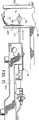
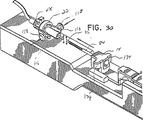
図13を参照すると、ハウジング14が、生検処置を行なうために、ドライバ案内プラットホーム180に取り付けられる。プラットホーム180は、典型的な画像装置の機器位置決めステージとの取付けを可能にするように形成され且つ寸法決めされている。このような装置の例として、米国コネチカット州ダンバリーのロード・コーポレーション(LORAD Corporation)又はコロラド州デンバーのフィッシャー・イメージング・コーポレーション(Fischer Imaging Corporation)から入手可能である。代わりに、装置10は、例えば、超音波のような他の適当な画像装置に適合するようにしてもよい。真空源(図示せず)は、真空ホース182により、真空ノブ28の近位端部分112に接続されている。プラットホーム180は、生検処置中、装置10を安定化させすると共にそれに電力を供給し且つ支持するために使用される。プラットホーム180は、遠位端部分186で部分的に包囲された領域184を備えている。この部分包囲領域184は、ハウジング14をプラットホーム180に対して固定位置に維持するための構造体をなしている。プラットホーム180の遠位端部分186は、支持管76をそれから延びるようにする開口188を形成している。ハウジング14は、プラットホーム180に取り付けられたブロック190により更に安定化されている。プラットホーム180は、ギヤ48と係合するギヤを駆動するモータを備え、更に、トリガにより開放される圧縮ばねを備え、このトリガは、約1.91cm(約3/4インチ)の最終距離装置10を突き出すように作動する。1つ又はそれ以上の制御ノブ193のような制御ノブが、ナイフ管50及び真空管32の前進と後退を制御するために設けられてもよい。
【0032】
図14及び15を参照すれば、手術中、患者の乳房192を可動クランプ194と定置クランプ196との間に配置する。可動クランプ192を定置クランプ194に向って移動させ、乳房192を可動クランプ192と定置クランプ194との間に捕える。乳房192を適所に固着させて、乳房192の目標組織塊198の像を撮る。撮像及び案内装置の位置決め性能を利用して、挿入端部分12を組織塊198と整列させるように装置10を目標組織塊198に向ける 。定置クランプ196は、挿入部分12を乳房192に入れる、定置クランプ196を貫通する開口200を構成する。乳房192への挿入前、ギヤシャフト、従ってナイフ管50を、トロカール84(図8)の横開口部128を囲むに十分、遠位方向に前進させる。外科医は、乳房192への進入を容易にすべく、メスを利用して、先端92の挿入箇所に手で切れ目を入れるのが良い。突き差し先端92を乳房の切れ目箇所に近づける。好ましくは、これを撮像及び案内装置の位置決め性能によって達成する。プラットホームの圧縮ばねに貯えられたエネルギーの解放によって、例えば、トリガー解放機構を作動させることによって、挿入部分12を乳房192の中へ遠位方向に前進させ、その結果、要求したように、挿入先端部分44は目標組織塊198に隣接して、或いはその中に位置する。
【0033】
図16を参照すれば、挿入部分12を目標組織塊198の中に前進させる。目標組織塊198を横開口部128に隣接して確実に位置決めするために、案内装置(図示せず)を、挿入部分12の位置を監視するのに使用するのが良い。上述したように、最初に、ナイフ管50を遠位方向に十分前進させ、ナイフ50管は先端92の近位端部分164に係合する。最小圧縮位置のばね80が組織ブラケット84とリング部分86との間に小さい力を付与して、剥離器プレート88を通常の後退位置に配置する。
【0034】
図17を参照すれば、ギヤシャフト46及びギヤ48を後退させることによって、ナイフ管50を近位方向に後退させる。1つの例示の実施形態では、ギヤ48は支持部材202に連結される。支持部材202は、駆動機構(図示せず)によって駆動される駆動ギヤ204を支持するのが良い。駆動機構は、駆動ギヤ204を回転させることによって、ギヤ48を回転させる。ギヤ48の近位方向及び遠位方向移動は、支持部材202を移動させることによって達成される。ギヤ48を十分遠位方向に前進させるとき、ギヤ48は停止体166とハウジング部分160の内面168から延びる突起206との間に捕えられる。前に説明したように、この位置は、先端92の近位端部分164に係合し、それにより、横開口部128を閉じるナイフ管50に対応する。突起206は片持ち部材208に取り付けられ、片持ち部材208は突起206の片寄りを許して、ギヤ48を突起206から解放し且つ近位方向に移動させるのを可能にする。ギヤを突起206を越えて移動させるとき、片持ち部材208は最初の位置に戻る。
【0035】
図18を参照すれば、ギヤ48を支持部材202及び駆動ギヤ204によって内面170に当接する位置に近位方向に十分後退させる。それにより、ナイフ管50は近位方向に後退し、横開口部128を目標組織塊198に露出させる。真空源(図示せず)から真空ホース182を経て、吸引を真空ノブ28を貫通する真空管32に付与する。
【0036】
図19及び20を参照すれば、装置10の斜視図が、ハウジングベース14のハウジング部分160の中の最も近位の位置に配置されたギヤシャフト46及びギヤ48を示す。ナイフ管を後退させて、組織バスケット84を露出させる。剥離器プレート88及び真空プレート130を横開口部128の中に示し、剥離端部分134はスロット154の中に延びる。
【0037】
図21を参照すれば、付与された吸引により、目標組織塊198の一部分を横開口部128に引き込む。吸引流の矢印210は、目標組織塊198に及ぼされる力の方向及び箇所を示す。吸引力は真空プレートの複数の孔132及び剥離器88の開口140を通る。
【0038】
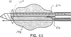
図22を参照すれば、吸引を所定時間にわたって維持して、横開口部128が所望量の目標組織塊198を横開口部128の中に採集することを可能にする。ナイフ管50を同時に回転且つ前進させ、ナイフ管50の遠位端に形成された環状ナイフ刃94を使用して、組織サンプル212を目標組織塊198から切断する。ナイフ管50を、図17を参照して説明した仕方と同じ仕方で、駆動ギヤ204及び支持部材202によってそれぞれ回転させ且つ遠位方向に前進させる。組織サンプル212がナイフ管50によって囲まれたとき、吸引はもはや必要なく、やめられる。
【0039】
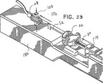
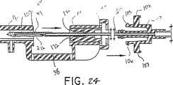
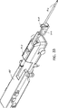
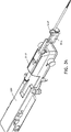
図23及び24を参照すれば、タブ106を孔114から解放すべくボタン108を押し下げることによって、真空ノブ28を取付ポート22から取外す。真空ノブ28を近位方向に移動させて、真空管32を後退させる。真空管32の近位方向移動により、先端部分44をナイフ管50から取出し、組織サンプル212を組織ベイ38に露出させる。所望ならば、真空管32の移動中、組織バスケット84の中の組織サンプル212を真空プレート130に保持すべく吸引を継続しても良い。真空管32を、リング部分86及びばね80が延長管120のボア124の中に配置されるまで後退させる。縁172は、リング部分86及びばね80をボア124の中に受入れるのを助けるために面取りされる。組織バスケット84がハウジング14の第2ボアから出始めるとき、組織サンプル212はハウジング14の組織受け入れ部分38の上方に保持される。真空管32を回転させ、組織バスケット84がハウジング14の組織受け入れ部分38に向って下向きに面しているのを確認する。
【0040】
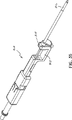
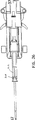
図25、26及び27を参照すれば、リング部分86は延長管120内の段付き部分214に係合する。真空管32の近位方向移動が続くとき、ばね80は組織バスケット84とリング部分86との間で圧縮され始める。ばね80を圧縮しながら、剥離端部分134を有する剥離器プレート88を遠位方向に前進させ、真空プレート130に係合させてスロット154内を走らせる。剥離器プレート88は前進しながら、組織サンプル212を真空プレート130から剥離させ、組織サンプル212は組織バスケット84の外に落ちる。検査用組織サンプル212は、今、収集される。
【0041】
図28及び29を参照すれば、装置10の好ましい実施形態を示す。図28は真空ノブ28の第1位置を示す。真空ノブ28は、上述し且つ図3に図示したように、タブ106を孔114の中に配置することによって取付ポート22に固着される。組織サンプル212の収集中、真空ノブ28を、図14乃至27を参照して上述した方法で真空管32に取付ける。組織サンプル212の収集中、真空管32を引抜くけれども、支持管76及びナイフ管50を乳房192の中に残すのが良い。
【0042】
組織サンプル212の採集後、真空管32を支持管12及びナイフ管50を通して乳房192に再挿入する(図14及び図15)。(1つ又は2以上の)追加の組織サンプルを同じ部位から摘出する。図29は、横開口部128の向きを角変位させるように回転される真空ノブ28を示す。真空ノブ28が回転れると、真空管32も回転され、横開口部128を角変位させることができる。横開口部128は、乳房192(図14及び図15)に挿入されたときに、目標組織塊の異なる部分198(図14及び図15)を装置10の単挿入により摘出することができるように、第1位置から回転される。穴114のタブ106によって真空ノブ28を取付ポート22に再固定することができる。これらの穴114は、真空ノブ28を複数の異なる回転位置に固定することができるように、取付ポート22の周囲に配置される。例えば、取付ポート22は、10個の穴、すなわち、5対の対向して配置された穴を提供することによって、10個の固定可能位置を有しても良い。各固定可能位置は、例えば、隣接した固定可能位置から約36度に等しい組織バスケット84の角変位(量)に相当する。
【0043】
図30及び図31を参照すると、取付ポート28はハウジング14から取り外し可能である。ハウジング14の組織受取部分38と異なる位置で組織サンプル216を取り出すのが望ましい。取付ポート22及び真空ノブ28は、これらを互いに固定したままで、取り外すことができる。ボタン118を押してタブ116をハウジング14の延長部分174から解放することができる。真空管32は、組織サンプル216を組織ブラケット84内に配置して、ハウジング14の中を近位方向に引く。組織サンプル216を備えた組織ブラケット84を、組織サンプル216を受け取るための遠隔位置容器(図示せず)上に位置決めする。真空ノブ28を、上述したように偏向タブ106によって取り外し、取付ポート22から遠ざかるように移動させる。真空管32を取付ポート22を通して引く。次いで、図25及び図26に関連して上述したように、組織サンプル216を組織バスケット84から剥離させる。図32を参照すると、生検処置中、或いは、生検処置後、乳房192へのアクセスを維持することが必要であるかもしれない。この目的のため、支持スライド60がハウジング14から取り外し可能である。支持管76が支持スライド60に取り付けられている。支持管76は、乳房192に再アクセスするのに追加の挿入を行わなくても良いようにするため、組織ブラケット84及びナイフ管50を再挿入することができるように乳房192へのアクセスを提供する。
【0044】
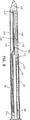
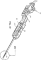
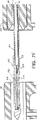
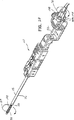
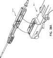
図33乃至図37を参照すると、生検処置を行うため、変形実施形態の生検装置310がドライバー案内プラットホーム180に取り付けられている。プラットホーム180は、定位画像装置の器具位置決めステージに取り付けられるように形作られ、寸法形状決めされ、このような定位画像装置は、コネチカット州ダンベリーのLORAD Corporation又はコロラド州デンバーのFischer Imaging Corporationから入手することができる。変形例として、装置310は、例えば超音波のような任意の他の適当な画像装置に取り付けられるようになっていても良い。装置310は、組織ベイ312が遠位端部314に取り付けられるように、形を変えられる。組織サンプル(図示せず)は、本質的に上述したように、切断され、回収される。図33はナイフ管316を完全前進位置で示し、図34はナイフ管316を後退位置で示す。図35を参照すると装置310が示されている。ナイフ管316は、生検処置中に組織サンプルを得たときに組織サンプルにアクセスするための開口部318を構成する。
【0045】
図38及び図38Aを参照すると、駆動ユニット411に取り付けられた、別の変形実施形態の経皮的生検装置410が図38及び図38Aに示され、駆動ユニット411は、定位画像装置(図示せず)の器具位置決めステージに取り付けられるように形作られ、寸法形状決めされている。駆動ユニツトの一例は、「生検器具駆動装置」の名称で、1998年2月20日に、出願された、本件と同様に譲渡された米国特許第6554779号に開示され、この出願の内容全体をここに援用する。生検処置を行うのに用いられる定位画像装置の例は、コネチカット州ダンベリーのLORAD Corporation又はコロラド州デンバーのFischer Imaging Corporationから商業的に入手することができる。変形例として、装置410は、例えば、ワシントン州シアトルのNeovisionから入手することができるような超音波画像装置のような他の適当な画像装置に取り付けられ、または、かかる装置と相互作用するようになっていても良い。
生検装置410は、上述した生検装置の実施形態10、310と構造的、作動的に同じである。従って、以下の生検装置410の説明は、装置410に関して異なる特徴に主に注意を集中する。
【0046】
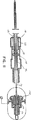
図40乃至図47を参照すると、生検装置410は、一連の同心に配置された管状部材を支持するハウジング412を有する。かかる第1の管状部材はナイフ管414であり、このナイフ管414は、その遠位端に形成された傾斜環状切断面416と、環状切断面416の近位方向に配置された横組織放出ポート又は開口部418とを有する。器具の作動中ナイフ管を移動させてしまうかも知れない流体などの排出を容易にするため、一連の排出穴420が、組織放出ポート又は開口部418の遠位方向の箇所で、ナイフ管414の側壁に形成される。流体などの除去を助けるため、横配向真空ポート421が、ハウジング412の遠位端に隣接して供され、使用者によって作動される真空源(図示せず)に連結されるのが好ましい。ギヤシャフト422が、ナイフ管414の近位端上に固定され、ギヤシャフト422上に配置されたボス426の周りに堅固に取り付けられたギャ424を有する。組立てられたナイフ管414は、ハウジング412に亘って長手方向に形成された軸線方向通路428に取り付けられる。ナイフ管414は、ナイフ管414の同時に起こる回転及び長手方向並進運動を容易にするように、軸線方向通路428に配置される。
【0047】
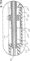
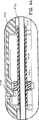
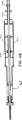
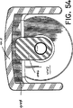
真空管430が、突き差し先端432がナイフ管414から環状切断面416を越えて延びるように、ナイフ管414内に同心状に配置されている。この構成では、突き差し先端432とナイフ管414とが、患者の組織、例えば、圧縮した胸部内に挿入することができる実質的に連続した突き差しアッセンブリーを形成する。図41−図43に最も良く示されているように、真空管430の遠位端に隣接して、組織バスケット434が形成されている。組織バスケット434は、横方向に向いており、組織支持プレート436によって構成され、この組織支持プレート436は、これに沿って長手方向に形成された一連の真空穴438と、これら一連の穴438から離れて形成された最も近位側の真空穴440とを備えている。真空穴440は、器具410からの真空力の損失の大き過ぎを防止するために、ナイフ管414(図52)の遠位端をシールするのを助けるように設けられ、その結果、残りの真空穴438が有効に目標組織を組織バスケット434に引き込むことができる。組織プレート436は、断面が円弧状をなし(図53A)、実質的に連続した表面凹部が真空管430の遠位端近傍に形成されるように、溶接などによって真空管430に固定されているのが好ましい。この組織プレート436の円弧または正弦曲線形状が、ナイフ管414が挿入箇所において器具410の最も外側の直径を表わす事実と組合わさって、他の既存の組織サンプル採取器具の幾何学配置より大きな組織サンプルを取ることを容易にする。
【0048】
図45と関連して図40を参照すると、長手方向ボア444を貫通して形成した係止ホイール及びインデクサ442が、真空管430の遠位端に隣接して取付けられている。係止ホイール442は、タブ部材446を備え、このタブ部材は、係止ホイール442が真空管430に取付けられたとき、組織バスケット434と径方向に整列させられる。係止された向きでは、タブ446は、ハウジング412に形成されたリップ448の後ろに配置される。この配置は、器具410を患者に挿入したとき、真空管430の、従って、突き差し先端432の近位方向への動きを防止する。加えて、小さなノッチ448が係止ホイール442に形成され、このノッチは、使用者に組織バスケット434の相対的な向きを視覚的に示すようにタブ446と整列している。真空ポートアダプタ450が、係止ホイールおよびインデクサ442に隣接して真空管430の遠位端に固定されている。真空ポートアダプタ450が、真空管430を真空にする真空源(図示せず)に連結された真空ホースの取付けを容易にする。
【0049】
組織剥離クリップ452によって、組織バスケット434からの組織サンプルの抽出は容易になり、この組織剥離クリップは、図46および図47に示されているように、ナイフ管414にクリップ留めされように形作られ且つ寸法決めされた横開口部のカラー部分454を有する変形板ばねの形態であり、組織放出開口部418と整列している。組織剥離クリップ452は、内方に向けられた遠位端部分456を含んでおり、この遠位端部分は、真空管430の外面に向けて付勢されており、真空管430をナイフ管414内に後退させたとき(図57および図57)、サンプル組織の剥離を容易にしている。組織剥離クリップ452は、更に、材料または潤滑剤の被覆を備え、抽出するサンプル組織と接触することになる組織剥離クリップ452の表面に沿った摩擦力を減らしてもよい。この構成では、組織剥離クリップ452への付着の可能性がより少なく、組織をより簡単に組織バスケットから取り出せることになる。適当な公知の摩擦減少コーティングを組織剥離クリップ452および/または組織プレート436に施してもよい。
【0050】
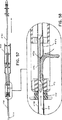
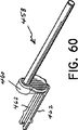
図39および図40を再度参照すると、放射線透過性外側管458が、摺動クリップ460に取付けられ、このクリップは遠位端でハウジング412への取り外し可能に取付けられている。外側管458は、放射線不透過性ステンレス鋼のナイフ管414および真空管430を存在させることなく、疑わしい組織を映像化するために組織サンプル採取部位に残せるよう、放射線透過性である。外側管458は、使用者に組織サンプル採取領域を示すために、組織バスケット434の長手方向間隔を示すように形成された放射線不透過ラインを備えているのが好ましい。
【0051】
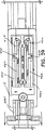
図59ないし図61を一時的に、そして、まず図59を参照すると、摺動クリップ460のハウジング412への取付けが示されている。特に、摺動クリップ460は、ハウジング412の下側に形成された平行な受けスロット464に嵌まる一対の偏向可能なレッグ462を備えている、一対の菱型カム面466が、平行なスロット464を分ける壁部分468に沿って形成されている。カム面466は、摺動クリップ460の長手方向の動きを妨げる一時係止部材として機能する。この抵抗を容易にするために、横方向に向いた一対のタブ470が、可撓性レッグ462の各々の外側に向いた部分に形成され、平行なスロット464の内側壁に対する、可撓性レッグ462の当接面をつくる。この構成では、可撓性レッグ462の近位部分474が、これらがカム面466上を通過するとき、外方に向かって片持ちされる。摺動カム面466上を摺動クリップ460が完全に遠位方向に動くと、外側管458の遠位端が、目標組織塊に挿入したとき、組織ブラケット434の位置の遠位端部分と整列し、疑わしい組織領域から器具412を取り出したとき、組織サンプリング部位の位置に対するマーカとなる。
【0052】
図48ないし図61を参照して、患者の胸部で行う生検処置と関連して使用する生検器具410の操作を説明する。しかしながら、後述する処置は、身体の他領域の組織の生検に関連しても利用できることがわかる。大部分の操作手順は、この開示の他の実施形態と関連して説明した操作手順と同一またはこれに類似する。従って、以下の説明は、主に、生検器具410の特徴に焦点を合わせる。しかしながら、他の実施形態のために上述した処置のいくつかを、読者の便宜のため、ここで再度説明する。
【0053】
図48に示すように、ドライバーユニット411に取り付けられた生検装置410を、正確な位置が定位画像装置の使用によってすでに確認されている疑わしい組織塊476と整列して位置決めする。ドライバーユニット411は定位画像テーブルの器具部に取り付けられている。定位画像装置の位置決め能力を利用して、貫通先端432が目標組織塊476の中心と整列するように生検装置410を位置決めする。組織バスケット434が組織バスケット434に対する組織塊476の長手方向全体距離に亘って跨るように、生検装置410を手動で組織塊の中を進めてもよい。目標組織塊が組織バスケット434の長さを越える処置の場合には、最初に器具を組織塊の一端まで全て挿入して、組織のこの端を前述の処置を通じて取り、次いで組織バスケットが除去されるべき残った組織サンプルと整列するように生検装置410を移動し、この処置を全ての目標組織サンプルが除去されるまで繰り返す。
【0054】
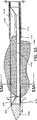
図50を参照すれば、生検装置410を組織サンプル476の中を挿入するとき、組織バスケットを所望の疑わしい組織塊476に隣接して位置決めする前に、いかなる組織も組織バスケットに早まって挿入しないように、ナイフ管414を組織バスケット434に亘って位置決めする。図51に示すように、一旦組織バスケット434を疑わしい組織塊476に適切に隣接して位置決めしたら、ギアー424をハウジング412(図44)上に配置された係止タ具478から開放することによって、ナイフ管414を近位方向に後退する。この仕方で、組織バスケット434を露出し、真空源をオンにして、組織バスケット434内に真空を作り、それによって組織バスケット434に隣接する疑わしい組織塊476の一部を引く。吸引を継続的に行うとともに、ナイフ管414を回転し、遠位方向に並進移動させ、環状切断表面416によって組織バスケット434に含まれた組織を切断する。ギアー424へのギアー入れによって連結された駆動ユニット412に設けられたモーターによって、ナイフ管414を回転させ、さらに遠位方向に進めるのが好ましい。
【0055】
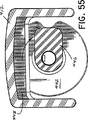
一旦ナイフ管を完全に遠位方向に進めたら、係止ホイール及びインデクサー442を回転させて、タブ446がハウジング412の上部構造を離し、それによって真空管430を開放し、さらに真空管の引き抜き、したがって組織バスケット434のナイフ管414からの引き抜きを可能にする。ユーザーは、タブ446と整列するノッチ448によって設けられた視覚的な指示によって、真空管434が自由に引き抜かれることを確認することができる。一旦真空管434を引き抜いて、組織バスケット434がナイフ管414内の放出開口部418に隣接したら、組織剥離クリップ452を組織バスケット434の中に入れて、内方に偏向した部分456を切断された組織サンプル476Aの近位端に接触させ、それによって図58に示すように、組織サンプルを組織バスケット434から遠ざかるようにする。
【0056】
所望量のサンプル採取を完了したら、外側管458を遠位方向に移動させて、外部管458に形成された放射線不透過性マーカーを患部の位置及び組織バスケット434が既に整列した位置の長さと整列して位置決めする。次いで外側管458を生検装置410から脱着し、更に装置を患者の組織から並進移動させて離し、生検装置410の残った要素の放射線不透過の性質からの干渉無しに組織を画像化するのがよい。画像化の終了の際、もし更なるサンプル採取が望まれるか或いは、必要であると決定されたら、生検装置410を外部管458の中に再挿入して、外部管458とハウジング412と再連結させ、前述のように更なるサンプル採取を行うのがよい。
【0057】
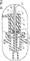
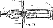
図62乃至65を参照すれば、既に述べた生検装置410と関連して用いられる組織マーキング装置をここに詳細に説明する。組織マーキング装置500は、遠位端から延びる細最可撓性管状シース504を備えたアクチュエーターハウジング502を有し、可撓性管状シース504の遠位端には、下部管506が固定されている。クリップ形成クランプ部材508が、アクチュエーター部材512に引っ張り可能に取り付けられたアクチュエーターケーブル510の遠位端に取り付けられている。ケーブル510は、段付型部516を備えたフェルール514を通じてアクチュエーター512に装着されており、この段付型部516はアクチュエーター部材512に形成された段付ゴア内に着座する。一対のホイルスプリング518及び520が、ハウジング内でアクチュエーター部材512のいずれかの側に設けられ、図64に示すように、アクチュエーター512をクランプ508のための展開状態に対応する初期方向に位置決めする相対ばね力を有する。ハウジング502は、一緒にスナップ嵌めされたハウジング構成要素522及び524を備えた分割ハウジングとして形成され、アクチュエーション構成要素を収容する。
【0058】
組み立てられるとき、ハウジング部分522及び524は、親指レスト526を形成して、組織マーキング装置500を作動するときユーザーの親指のための支え面をなす。アクチュエーター512は、半径方向に延びる対向した支え面528及び530を有し、ユーザーは注射器のような仕方で、支え面を握って患者内の生検位置にクリップ532を展開し、さらに固定する。組織マーキング装置500は、患者内の生検位置にクリップ532を展開しさらに固定する。組織マーキング装置500は、一対のマーキングバンド534および536を更に有し、これらのバンド534及び536は、組織マーキング装置を生検装置410に対して指向するのを補助する。
【0059】
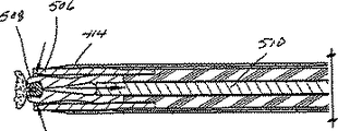
図66乃至73を参照すれば、使用の際、組織マーキング装置500をナイフ管414の組織放出開口部418内に挿入して、図68に示すように、組織マーカー装置500の遠位端を環状切断面416を越えてナイフ管414の遠位端から延ばす。組織マーカー装置500の遠位端は、生検装置410の長手方向軸線と整列してクリップ配置するために、ナイフ管414を中央で貫通し、さらに中央でナイフ管414から出るのが有利である。組織マーキングバンド536及び534を、図67に示すように、組織放出開口部418の遠位端をまたがらせるとき、ユーザーはこのような整列の視覚的な指示を得る。組織マーキング装置500が生検装置410に挿入された状態で、ユーザーは注射器のブランジャーを握るのと多分におなじ仕方で組織マーキング装置を握り、さらにアクチュエーター512の組織フィンガー付勢面528及び530上で引き戻す。この動作によって、ケーブル510は近位方向に引かれ、それによってクリップ形成クランプ508をカム管506内で引いて、クリップ532をサンプル採取された組織の患部に取り付ける。この仕方では、生検装置410並びに外部管458を患者から完全に取り外し、それによって生検部位をマークして、たとえば患部の更なる画像化の更なる参考のために、あるいは万一患部の更なる生検が必要となった場合に、生検の正確な位置の指示を与える。
【0060】
ここに開示した実施例に対して種種の修正がなされうることを理解すべきである。従って、上述の説明は限定ではなく単なる好ましい実施例の例示として解釈すべきである。当業者なら添付した請求の範囲及び精神の範囲内で修正を思いつくであろう。
【図面の簡単な説明】
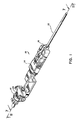
【図1】 本発明の開示に従って構成した経皮的生検装置の1つの実施形態の斜視図である。
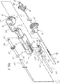
【図2】 図1の生検装置の実施形態の分解斜視図である。
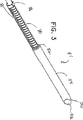
【図3】 図1の生検装置の実施形態の先端部分の拡大斜視図である。
【図4】 図1の生検装置の実施形態の真空アセンブリーの分解斜視図である。
【図5】 図4の線5-5における断面図である。
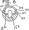
【図6】 図4の線6-6における断面図である。
【図7】 図1の線7-7における横断面図である。
【図8】 図7中に指示した詳細領域の拡大横断面図である。
【図9】 図7中に指示した詳細領域の拡大横断面図である。
【図10】 図7中に指示した詳細領域の拡大横断面図である。
【図11】 図1の線11-11における生検装置の横断面図である。
【図12】 図11中に指示した詳細領域の拡大横断面図である。
【図13】 案内及び駆動プラットホームに取付けられた生検装置の斜視図である。
【図14】 突き差し先端を挿入する前のクランプされた乳房を示す、生検装置の側面図である。
【図15】 突き差し先端を目標組織塊に挿入した後のクランプされた乳房を示す、生検装置の側面図である。
【図16】 ナイフ管を十分前進させた、目標組織塊の中に配置された生検装置の遠位部分の拡大横断面図である。
【図17】 近位方向に移動したギヤ及びギヤシャフトを示す、生検装置のハウジング部分の拡大横断面図である。
【図18】 十分に後退したギヤ及びギヤシャフトを示す、生検装置の横断面図である。
【図19】 生検装置の底面からの斜視図である。
【図20】 図19中に指示した詳細領域を示す、生検装置の先端の拡大斜視図である。
【図21】 吸引管路、及び生検装置に形成された横開口部に引き込まれた組織塊を示す、図18中に指示した詳細領域の拡大横断面図である。
【図22】 回転し且つ十分前進して、生検装置の横開口部内の組織塊を切断したナイフ管を示す、図18中に指示した詳細領域の拡大横断面図である。
【図23】 真空管及び先端部分を後退させるために取付ポートから取外した真空ノブを示す、案内駆動プラットホームに取り付けられた生検装置の近位部分の斜視図である。
【図24】 真空管及び先端部分を後退させるために取付ポートから取外した真空ノブを示す、生検装置の遠位部分の横断面図である。
【図25】 組織を装置から取り出す前の剥離器プレート及び組織サンプルを示す、生検装置先端部分の横断面図である。
【図26】 組織を装置から取り出す間の剥離器プレート及び組織サンプルを示す、生検装置先端部分の横断面図である。
【図27】 組織を装置から取り出す間の剥離器プレート及び組織サンプルを示す、生検装置先端部分の拡大斜視図ある。
【図28】 真空ノブを第1位置で示す、生検装置の斜視図である。
【図29】 真空ノブを図29の第1位置から回転させた第2位置で示し、且つ回転させた横開口部を示す、生検装置の斜視図である。
【図30】 取外され且つ後退した取付ポートを示す、生検装置の一部分の斜視図である。
【図31】 生検装置から取り出された組織サンプルの斜視図である。
【図32】 支持管を保持した乳房の斜視図である。
【図33】 遠位端に組織トレイを有する、プラットホームに取り付けられた生検装置の斜視図である。
【図34】 ナイフ管を後退させた、図33の生検装置の斜視図である。
【図35】 遠位端に組織トレイを有する生検装置の斜視図である。
【図36】 図33の生検装置の側面図である。
【図37】 図36の線37-37における横断面図である。
【図38】 本発明の開示に従って構成した経皮的生検装置の変形の実施形態の斜視図である。
【図38A】生検装置を駆動ユニットに取外し可能に取り付けるのを示す部分的な斜視図である。
【図39】 図38の経皮的生検装置の使い捨て載せユニット部分の斜視図である。
【図40】 図39の使い捨て載せユニットの構成部品を示す、部品別の斜視図である。
【図41】 生検装置の組織受入れバスケットを図示する、使い捨て載せユニットの遠位端部分の拡大斜視図である。
【図42】 図39の線42-42における横断面図である。
【図43】 図42中に指示した詳細領域の拡大図である。
【図44】 図42中に指示した詳細領域の拡大図である。
【図45】 図42中に指示した詳細領域の拡大図である。
【図46】 図39の線46-46における横断面図である。
【図47】 図46中に指示した詳細領域の拡大図である。
【図48】 突き差し先端を挿入する前の、生検装置とクランプされた乳房の中の目標組織手段との相対的な整列を図示する側面図である。
【図49】 図39の生検装置の実施形態による目標組織の突き刺しを示す、図48と同様に図である。
【図50】 ナイフ管を十分前進させた、目標組織塊の中に配置された生検装置の遠位端部分の拡大図である。
【図51】 ナイフ管を後退させた生検装置を示す、側面横断面図である。
【図52】 ナイフ管を十分後退させ、且つ、真空源が生検装置の組織バスケットに吸引を付与する、目標組織塊の中に配置された生検装置の遠位端部分の拡大横断面図である。
【図53】 回転し且つ遠位方向に前進し、それにより、生検装置の組織バスケットの中に囲まれた組織を切断したナイフ管を示す、図52と同様の図である。
【図53A】図53の線53A-53Aにおける組織バスケットの断面図である。
【図54】 図42の線54-54における遠位方向から見た断面図である。
【図55】 真空管係止機構の解放を示す、図54と同様の図である。
【図56】 図55に指示した移動と一致する組織バスケット及び真空管の回転を示す、生検装置の破断斜視図である。
【図57】 使い捨て載せユニットからの真空管の引き出しを示す、生検装置の横断面図である。
【図58】 切断した組織サンプルを生検装置の組織バスケットの中から剥離するのを示す、図57に指示した詳細領域の拡大図である。
【図59】 生検装置の使い捨て載せユニットからの外側管の取外しを示す、図39の線59-59における横断面図である。
【図60】 生検装置の外側間の斜視図である。
【図61】 生検装置を取り出した後の患者の乳房に保持された、図60の外側管を示す側面横断面図である。
【図62】 本発明の開示に従って構成された組織マーキング装置の斜視図である。
【図63】 図62中に指示した詳細領域の拡大図である。
【図64】 図62の組織マーキング装置の遠位端部分の部分的な拡大斜視図である。
【図65】 図62の組織マーキング装置の構成要素を示す、部品別の斜視図である。
【図66】 生検装置のナイフ管に挿入された、図62の組織マーキング装置の斜視図である。
【図67】 図66中に指示した詳細領域の拡大図である。
【図68】 図66中に指示した詳細領域の拡大図である。
【図69】 生検装置及び患者の乳房組織に挿入された組織マーキング装置の横断面図である。
【図70】 図69中に指示した詳細領域の拡大図である。
【図71】 クリップが組織サンプリング部位の組織の周りに配置された、組織マーキング装置の遠位端部分の横断面図である。
【図72】 組織マーキング装置の近位端部分の横断面図である。
【図73】 組織サンプリング部位のクリップの展開及び形態を示す、図71と同様の図である。[0001]
【Technical field】
The present disclosure relates to tissue specimen biopsy devices, and more particularly to single-insertion, multi-sample transcutaneous biopsy devices.
[0002]
[Background of related technology]
It is often necessary to sample tissue to diagnose and treat patients suspected of having cancerous tumors, pre-malignant conditions and other illnesses. Typically, in the case of suspected cancerous tissue, the cell is cancerous when the surgeon establishes that the suspected condition is present by a procedure such as palpation, X-ray or ultrasound imaging. A biopsy is done to determine the home. Biopsy is done by open or percutaneous techniques. An open biopsy takes the entire mass (resected biopsy) or part of the mass (incision biopsy). On the other hand, percutaneous biopsy is usually done with a needle-like instrument and is either fine needle aspiration (FNA) or core biopsy. In a fine needle aspiration biopsy, individual cells or clusters of cells are obtained for cytology and prepared, for example, with a Papanicolaou smear. In a core biopsy, as the term suggests, core or fragment tissue is obtained for histology, and histology is done via frozen or paraffin sections. In more recent developments, transcutaneous techniques have been used to remove the entire mass during initial treatment.
[0003]
The type of biopsy utilized is largely determined by the circumstances that appear in the patient, and a single procedure is not ideal in all cases. However, core biopsies are extremely useful for many conditions and are very often used.
Complete tissue from an organ or lesion is preferred by medical personnel to arrive at a clear diagnosis of the patient's condition. In most cases, only a portion of the organ or lesion needs to be sampled. The excised tissue portion represents the organ or lesion as a whole. In the past, surgery has been performed to ensure that tissue is located, identified, and taken in order to obtain appropriate tissue from organs or lesions within the body. Current technology uses medical imaging devices such as stereotactic X-rays, fluoroscopy, computed tomography, ultrasound, nuclear medicine, and magnetic resonance imaging. These techniques make it possible to identify deep tiny things in the body. However, clear tissue characterization still requires obtaining a tissue sample suitable for characterizing the organ or lesion tissue.
[0004]
Mammography can identify breast abnormalities that are not palpable (not recognizable by finger examination) faster than breast abnormalities can be diagnosed by physical examination. Most palpable breast abnormalities are benign, but some are malignant. When diagnosing breast cancer before it becomes palpable, breast cancer mortality can be reduced. It is still difficult to determine if a pre-tactable breast abnormality is malignant. That is, some benign lesions have a mammographic feature that mimics a malignant lesion, and some malignant lesions have a mammographic feature that mimics a benign lesion. Thus, mammography has its limitations. In order to reach a clear diagnosis, tissue must be taken from within the breast and examined under a microscope.
[0005]
The introduction of fixed-guided percutaneous breast biopsy provided an alternative to open surgical breast biopsy.
Before long These teaching methods have become more accurate and easier to use. Biopsy guns were introduced for use in conjunction with these teaching methods. The exact placement of the biopsy gun is a useful biopsy because only one small core can be obtained per insertion at one location. information It was important to get In order to carefully sample the lesion, many separate insertions of the instrument had to be made.
[0006]
Biopsy procedures can benefit from large tissue samples to be taken, eg, tissue samples as small as 10 mm in diameter. Many of the prior art devices required multiple punctures to the breast or organ to obtain the required sample. This practice is tedious and time consuming.
[0007]
One further solution for obtaining large tissue samples is to utilize a device that can take multiple tissue samples with a single insertion of the instrument. An example of such a device can be found in US Pat. No. 5,195,533 to Chin et al. This patent describes a technique for extracting multiple samples with a single insertion of a biopsy device. Typically, such a biopsy instrument draws a tissue sample through an external vacuum source into a hollow needle or cuts the tissue sample and houses it in a notch formed in the mouth needle. A tissue sample is removed from the tissue mass. Typical of such devices are U.S. Pat. No. 5,524,101 issued to Kairouette and U.S. Pat. No. 5,185,302 issued to Terwilliger. Such devices are generally intended to advance a hollow needle into a tissue mass, apply a vacuum force to suck the sample into the needle, and hold the tissue sample in the needle while removing the tissue. .
[0008]
When extracting multiple samples using a vacuum to inhale or remove tissue from the body with a single insertion of a biopsy device, it is important that the vacuum path is not clogged. If the vacuum path is clogged, sample collection becomes difficult or impossible. This requires multiple insertions of the device or can reduce the sample mass per extraction.
[0009]
Accordingly, there is a continuing need for a percutaneous biopsy device and method that can reliably remove an appropriate biopsy sample with a single insertion of a biopsy instrument.
[0010]
Summary of the Invention
One particular embodiment of the present invention comprises a housing and a first elongate tubular member removably disposed within the housing and defining a fluid passageway, wherein the first elongate tubular member is tissue. Tapered to pierce With Closed distal end portion and taber With closure Distal end portion Including a transversely disposed tissue receiving opening that includes a tissue support surface that defines a plurality of holes in fluid communication with the fluid passageway, and is coaxially rotatable and reciprocating about a first elongated tubular member A second elongate tubular member operatively disposed, the second elongate tubular member having a blade formed at the open distal end and a transverse tissue release formed in a proximal direction of the blade; Aperture A surgical biopsy device is provided.
[0011]
A third elongated tubular member is removably supported by the housing and coaxially disposed about the first and second elongated tubular members, the third elongated tubular member being movable from a retracted position to an extended position. In the extended position, the distal end portion is laterally disposed adjacent to the distal-most position of the tissue receiving opening of the first elongate tubular member. The third elongate tubular member may be radiolucent to allow passage of X-rays, and includes a radiopaque marking formed on a portion of the third elongate tubular member, the third elongate tubular When the member is in the deployed position, the radiopaque marking may be laterally adjacent to the distal-most position of the first elongate tubular member tissue receiving opening.
[0012]
In one aspect of the biopsy device, tissue ablation clip Next to Direction Tissue release Aperture Placed adjacent to and exfoliated clip The tissue receiving opening and transverse tissue release With opening Alignment Sometimes A flexible extension is configured and dimensioned to enter the tissue receiving opening of the first elongate tubular member. Tissue peeling clip The tissue exfoliation clip Tissue detachment to reduce friction with body tissue in contact with clip A friction reducing coating formed on the substrate may be included.
[0013]
In another aspect of the biopsy device disclosed herein, the tissue support surface of the laterally disposed tissue receiving opening has an arcuate cross section.
[0014]
In other embodiments, the present disclosure includes a housing and a first elongate tubular member removably disposed within the housing and defining a fluid passageway, wherein the first elongate tubular member includes tissue. Tapered taper With Closed distal end portion and taber With closure Distal end portion A second elongate tubular member including a transversely disposed tissue receiving opening formed near the first elongate tube and coaxially rotatable about the first elongate tubular member and reciprocally disposed; Two elongate tubular members have a blade formed at the open distal end and a transverse tissue release formed in the proximal direction of the blade Aperture And a tissue marking member removably insertable into the second elongate tubular member, the tissue marking member comprising an elongate shaft and a clamp disposed at a distal end of the elongate shaft, wherein the clamp A surgical student operable from a first orientation configured and dimensioned to hold the tissue marker to a second orientation that deforms the tissue marker held by the clamp and thereby attaches the tissue marker to the patient's body tissue Provide inspection equipment.
[0015]
In another form, the present disclosure includes a) inserting a biopsy device into a patient's tissue, wherein the biopsy device is tapered at a distal end. With An inner tubular member having a piercing end, and an outer tubular member fixedly held longitudinally relative to the inner tubular member during the insertion stage; b) the outer tubular member is retracted from the inner tubular member to form an inner tubular member Exposing the laterally arranged tissue receiving area formed; c) applying suction to a series of openings formed along the inner surface of the tissue receiving area to draw the tissue into the tissue receiving area; c) As the outer tubular member passes over the tissue receiving region, the outer tubular member is advanced over the inner tubular member and disposed within the tissue receiving region such that the cutting surface formed at the distal end of the outer tubular member rotates. Cutting the tissue, and d) tissue cut by retracting the inner tubular member from the outer tubular member until the tissue receiving region is aligned with the lateral opening formed in the outer tubular member. Includes a step of taking out the sample from the tissue sampling site, the tissue separation plate pushes the tissue sample from the tissue receiving region, provides a method of performing a surgical biopsy.
[0016]
DESCRIPTION OF PREFERRED EMBODIMENTS
The present disclosure relates to devices for biopsy of tissue specimens, and more particularly to single-insertion multi-sample percutaneous biopsy devices and methods. In general, the device includes a series of concentric members, the innermost member of the series of concentric members including a tip portion having a lateral opening that is introduced into a target tissue mass of the patient's breast. At least a portion of the target tissue mass is drawn into the lateral opening by applying suction communicated with the region adjacent to the lateral opening via the vacuum plate. The knife tube is advanced distally around the outside of the vacuum tube while rotating to cut the target tissue portion from the surrounding tissue mass. Once the target tissue portion has been cut, the vacuum tube with the tip portion is retracted through the knife tube and the sample is removed. In particular, when retracted, the lateral opening is exposed adjacent to the tissue receiving position. By retracting the vacuum tube to the tissue receiving position, the peeler plate contacts the target tissue portion to remove the target tissue portion from the vacuum tube, and preferably drops the target tissue portion into the receiver.
[0017]
Referring now more particularly to the drawing in which the same reference numerals identify similar or identical elements throughout the several views, and referring first to FIG. 1, one embodiment of a percutaneous biopsy device is shown in its entirety. It is shown as 10. The
Referring to FIG. 2, the
[0018]
A
[0019]
A
[0020]
A
[0021]
Referring to FIG. 3, an enlarged view of the distal end portion of the
[0022]
Referring to FIG. 4, the vacuum assembly 9 includes a vacuum hub subassembly 18 (FIG. 1). Includes
[0023]
The mounting
[0024]
A
[0025]
The tissue stripping
[0026]
With reference to FIGS. 4-6, the
[0027]
With reference to FIGS. 7-10, a
[0028]
Referring to FIG. 8, the
[0029]
Referring to FIG. 9, the
Referring to FIG. 10, the
[0030]
Referring to FIG. 11, a
[0031]
Referring to FIG. 12, the
Referring to FIG. 13, the
[0032]
Referring to FIGS. 14 and 15, the patient's breast 192 is placed between the
[0033]
Referring to FIG. 16, the
[0034]
Referring to FIG. 17, the
[0035]
Referring to FIG. 18, the
[0036]
With reference to FIGS. 19 and 20, a perspective view of the
[0037]
Referring to FIG. 21, a portion of the
[0038]
Referring to FIG. 22, aspiration is maintained for a predetermined time to allow the
[0039]
Referring to FIGS. 23 and 24, the
[0040]
Referring to FIGS. 25, 26 and 27, the
[0041]
28 and 29, a preferred embodiment of the
[0042]
After collection of the
[0043]
Referring to FIGS. 30 and 31, the
[0044]
Referring to FIGS. 33 to 37, a
[0045]
38 and 38A, another alternative embodiment of a
The
[0046]
40-47, the
[0047]
A
[0048]
Referring to FIG. 40 in conjunction with FIG. 45, a locking wheel and
[0049]
[0050]
Referring again to FIGS. 39 and 40, a radiolucent
[0051]
59-61 temporarily and first with reference to FIG. 59, the attachment of the sliding
[0052]
The operation of the
[0053]
As shown in FIG. 48, the
[0054]
Referring to FIG. 50, when the
[0055]
Once the knife tube has been advanced fully distally, the locking wheel and
[0056]
Once the desired amount of sampling has been completed, the
[0057]
62 through 65, the tissue marking device used in connection with the
[0058]
When assembled,
[0059]
66-73, in use, the
[0060]
It should be understood that various modifications can be made to the embodiments disclosed herein. Therefore, the above description should not be construed as limiting, but merely as exemplifications of preferred embodiments. Those skilled in the art will envision modifications within the scope and spirit of the claims appended hereto.
[Brief description of the drawings]
FIG. 1 is a perspective view of one embodiment of a percutaneous biopsy device constructed in accordance with the present disclosure.
FIG. 2 is an exploded perspective view of an embodiment of the biopsy device of FIG.
3 is an enlarged perspective view of the distal end portion of the embodiment of the biopsy device of FIG. 1. FIG.
4 is an exploded perspective view of the vacuum assembly of the embodiment of the biopsy device of FIG. 1. FIG.
5 is a cross-sectional view taken along line 5-5 of FIG.
6 is a cross-sectional view taken along line 6-6 of FIG.
7 is a cross-sectional view taken along line 7-7 in FIG.
FIG. 8 is an enlarged cross-sectional view of a detailed region indicated in FIG.
FIG. 9 is an enlarged cross-sectional view of a detailed area indicated in FIG. 7;
FIG. 10 is an enlarged cross-sectional view of a detailed region indicated in FIG.
11 is a cross-sectional view of the biopsy device taken along line 11-11 in FIG.
12 is an enlarged cross-sectional view of a detailed area indicated in FIG.
FIG. 13 is a perspective view of a biopsy device attached to a guide and drive platform.
FIG. 14 is a side view of a biopsy device showing a clamped breast prior to insertion of a piercing tip.
FIG. 15 is a side view of a biopsy device showing the clamped breast after the piercing tip has been inserted into the target tissue mass.
FIG. 16 is an enlarged cross-sectional view of the distal portion of the biopsy device positioned within the target tissue mass with the knife tube fully advanced.
FIG. 17 is an enlarged cross-sectional view of the housing portion of the biopsy device showing the gear and gear shaft moved proximally.
FIG. 18 is a cross-sectional view of the biopsy device showing the gear and gear shaft fully retracted.
FIG. 19 is a perspective view from the bottom of the biopsy device.
FIG. 20 is an enlarged perspective view of the distal end of the biopsy device showing the detailed area indicated in FIG. 19;
FIG. 21 is an enlarged cross-sectional view of the detailed region indicated in FIG. 18 showing the aspiration duct and the tissue mass drawn into the lateral opening formed in the biopsy device.
FIG. 22 is an enlarged cross-sectional view of the detailed region indicated in FIG. 18 showing the knife tube rotated and fully advanced to cut the tissue mass in the lateral opening of the biopsy device.
FIG. 23 is a perspective view of the proximal portion of the biopsy device attached to the guide drive platform showing the vacuum knob and the vacuum knob removed from the attachment port to retract the tip portion.
FIG. 24 is a cross-sectional view of the distal portion of the biopsy device showing the vacuum knob and the vacuum knob removed from the attachment port to retract the tip portion.
FIG. 25 is a cross-sectional view of the tip of a biopsy device showing the peeler plate and tissue sample prior to removal of tissue from the device.
FIG. 26 is a cross-sectional view of the biopsy device tip section showing the peeler plate and tissue sample during removal of tissue from the device.
FIG. 27 is an enlarged perspective view of the tip of the biopsy device showing the peeler plate and tissue sample during removal of tissue from the device.
FIG. 28 is a perspective view of a biopsy device showing the vacuum knob in a first position.
FIG. 29 is a perspective view of the biopsy device showing the vacuum knob in a second position rotated from the first position of FIG. 29 and showing the rotated lateral opening.
FIG. 30 is a perspective view of a portion of a biopsy device showing the mounting port removed and retracted.
FIG. 31 is a perspective view of a tissue sample taken from a biopsy device.
FIG. 32 is a perspective view of a breast holding a support tube.
FIG. 33 is a perspective view of a biopsy device attached to a platform having a tissue tray at the distal end.
34 is a perspective view of the biopsy device of FIG. 33 with the knife tube retracted. FIG.
FIG. 35 is a perspective view of a biopsy device having a tissue tray at the distal end.
36 is a side view of the biopsy device of FIG. 33. FIG.
37 is a cross-sectional view taken along line 37-37 in FIG. 36.
FIG. 38 is a perspective view of an alternate embodiment of a percutaneous biopsy device constructed in accordance with the present disclosure.
38A is a partial perspective view showing the biopsy device being removably attached to a drive unit. FIG.
39 is a perspective view of a disposable mounting unit portion of the percutaneous biopsy device of FIG. 38. FIG.
40 is a perspective view of each component showing the components of the disposable loading unit of FIG. 39. FIG.
FIG. 41 is an enlarged perspective view of the distal end portion of the disposable loading unit illustrating the tissue receiving basket of the biopsy device.
42 is a cross-sectional view taken along line 42-42 of FIG. 39. FIG.
FIG. 43 is an enlarged view of a detailed area indicated in FIG.
44 is an enlarged view of a detailed area indicated in FIG. 42. FIG.
45 is an enlarged view of a detailed area indicated in FIG. 42. FIG.
46 is a cross-sectional view taken along line 46-46 of FIG. 39. FIG.
47 is an enlarged view of a detailed area indicated in FIG. 46. FIG.
FIG. 48 is a side view illustrating the relative alignment of the biopsy device and the target tissue means in the clamped breast prior to insertion of the piercing tip.
FIG. 49 is a view similar to FIG. 48, showing a target tissue puncture according to the embodiment of the biopsy device of FIG. 39;
FIG. 50 is an enlarged view of the distal end portion of the biopsy device positioned within the target tissue mass with the knife tube fully advanced.
FIG. 51 is a side cross-sectional view showing a biopsy device with the knife tube retracted.
FIG. 52 is an enlarged cross-sectional view of the distal end portion of the biopsy device positioned within the target tissue mass with the knife tube fully retracted and a vacuum source providing suction to the tissue basket of the biopsy device. It is.
FIG. 53 is a view similar to FIG. 52, showing the knife tube rotating and advanced distally, thereby cutting the tissue enclosed within the tissue basket of the biopsy device.
53A is a cross-sectional view of the tissue basket at
54 is a cross-sectional view seen from the distal direction along line 54-54 in FIG. 42;
FIG. 55 is a view similar to FIG. 54, showing the release of the vacuum tube locking mechanism.
FIG. 56 is a cutaway perspective view of the biopsy device showing the rotation of the tissue basket and vacuum tube consistent with the movement indicated in FIG. 55.
FIG. 57 is a cross-sectional view of the biopsy device showing the withdrawal of the vacuum tube from the disposable placement unit.
FIG. 58 is an enlarged view of the detailed area indicated in FIG. 57 showing the cut tissue sample being peeled from the tissue basket of the biopsy device.
59 is a cross-sectional view taken along line 59-59 of FIG. 39, showing removal of the outer tube from the disposable loading unit of the biopsy device.
FIG. 60 is a perspective view of the outside of the biopsy device.
61 is a side cross-sectional view of the outer tube of FIG. 60 retained on the patient's breast after removal of the biopsy device. FIG.
FIG. 62 is a perspective view of a tissue marking device constructed in accordance with the present disclosure.
FIG. 63 is an enlarged view of a detailed area indicated in FIG. 62;
64 is a partially enlarged perspective view of the distal end portion of the tissue marking device of FIG. 62. FIG.
FIG. 65 is a perspective view of each part showing components of the tissue marking device of FIG. 62;
66 is a perspective view of the tissue marking device of FIG. 62 inserted into a knife tube of a biopsy device. FIG.
67 is an enlarged view of a detailed area indicated in FIG. 66. FIG.
68 is an enlarged view of a detailed area indicated in FIG. 66. FIG.
FIG. 69 is a cross-sectional view of a biopsy device and a tissue marking device inserted into the breast tissue of a patient.
FIG. 70 is an enlarged view of a detailed area indicated in FIG. 69.
FIG. 71 is a cross-sectional view of a distal end portion of a tissue marking device with a clip disposed around tissue at a tissue sampling site.
72 is a cross-sectional view of a proximal end portion of a tissue marking device. FIG.
FIG. 73 is a view similar to FIG. 71, showing the deployment and configuration of the clip at the tissue sampling site.
Claims (14)
ハウジング内に取り外し自在に設けられ、流体通路を構成する第1の細長い管状部材と、を有し、該第1の細長い管状部材が、
組織を突き刺すようになったテーパ付き閉鎖遠位端部分、及び
テーパ付き閉鎖遠位端部分の近くに形成され、流体通路と流体連通した複数の穴を構成する組織支持面を含む横配置の組織受け入れ開口部を含み、
第1の細長い管状部材を中心に同軸に回転自在に且つ往復運動可能に配置された第2の細長い管状部材を含み、該第2の細長い管状部材が、開放遠位端に形成された刃及び刃の近位方向に形成された横組織放出開口部を有する、外科生検装置。A housing;
A first elongate tubular member removably provided within the housing and defining a fluid passageway, the first elongate tubular member comprising:
Tapered closed distal end portion adapted to pierce the tissue, and is formed near the tape path with a closed distal end portion, the lateral arrangement including a tissue support surface forming a plurality of holes in fluid passage in fluid communication with Including a tissue receiving opening,
A second elongate tubular member disposed coaxially and reciprocally about a first elongate tubular member, the second elongate tubular member including a blade formed at an open distal end; A surgical biopsy device having a transverse tissue discharge opening formed proximal to the blade.
ハウジング内に取り外し自在に設けられ、流体通路を構成する第1の細長い管状部材と、を有し、該第1の細長い管状部材が、
組織を突き刺すようになったテーパ付き閉鎖遠位端部分、及びテーパ付き閉鎖遠位端部分の近くに形成された横配置の組織受け入れ開口部を含み、
第1の細長い管状部材を中心に同軸に回転自在に且つ往復運動可能に配置された第2の細長い管状部材を含み、該第2の細長い管状部材が、開放遠位端に形成された刃及び刃の近位方向に形成された横組織放出開口部を有し、
第2の細長い管状部材の中に取り出し自在に挿入できる組織マーキング部材を含み、組織マーキング部材が
細長いシャフトと、
細長いシャフトの遠位端に配置されたクランプと、を含み、クランプが、組織マーカーを保持するように構成且つ寸法決めされた第1の向きからクランプによって保持された組織マーカーを変形させそれによって組織マーカーを患者の身体組織に取り付ける第2の向きまで作動できる、外科生検装置。A housing;
A first elongate tubular member removably provided within the housing and defining a fluid passageway, the first elongate tubular member comprising:
Tapered closed distal end portion adapted to pierce the tissue, and include a tissue receiving opening of the lateral arrangement is formed near the tape path with a closed distal end portion,
A second elongate tubular member disposed coaxially and reciprocally about a first elongate tubular member, the second elongate tubular member including a blade formed at an open distal end; A transverse tissue discharge opening formed in the proximal direction of the blade;
A tissue marking member removably insertable into the second elongate tubular member, wherein the tissue marking member is an elongate shaft;
A clamp disposed at the distal end of the elongate shaft, wherein the clamp deforms the tissue marker held by the clamp from a first orientation configured and dimensioned to hold the tissue marker, and thereby tissue A surgical biopsy device operable to a second orientation for attaching a marker to a patient's body tissue.
Applications Claiming Priority (7)
| Application Number | Priority Date | Filing Date | Title |
|---|---|---|---|
| US5954597P | 1997-09-19 | 1997-09-19 | |
| US5954897P | 1997-09-19 | 1997-09-19 | |
| US09/040,244 | 1998-02-20 | ||
| US09/040,244 US6142955A (en) | 1997-09-19 | 1998-02-20 | Biopsy apparatus and method |
| US60/059,548 | 1998-02-20 | ||
| US60/059,545 | 1998-02-20 | ||
| PCT/US1998/019422 WO1999015079A1 (en) | 1997-09-19 | 1998-09-16 | Biopsy apparatus and method |
Publications (3)
| Publication Number | Publication Date |
|---|---|
| JP2001517470A JP2001517470A (en) | 2001-10-09 |
| JP2001517470A5 JP2001517470A5 (en) | 2006-01-05 |
| JP4253121B2 true JP4253121B2 (en) | 2009-04-08 |
Family
ID=27365682
Family Applications (1)
| Application Number | Title | Priority Date | Filing Date |
|---|---|---|---|
| JP2000512457A Expired - Fee Related JP4253121B2 (en) | 1997-09-19 | 1998-09-16 | Surgical biopsy device |
Country Status (7)
| Country | Link |
|---|---|
| US (1) | US6142955A (en) |
| EP (1) | EP1026992B1 (en) |
| JP (1) | JP4253121B2 (en) |
| AU (1) | AU728656B2 (en) |
| CA (1) | CA2303814A1 (en) |
| ES (1) | ES2375048T3 (en) |
| WO (1) | WO1999015079A1 (en) |
Families Citing this family (196)
| Publication number | Priority date | Publication date | Assignee | Title |
|---|---|---|---|---|
| US8668737B2 (en) | 1997-10-10 | 2014-03-11 | Senorx, Inc. | Tissue marking implant |
| US7637948B2 (en) | 1997-10-10 | 2009-12-29 | Senorx, Inc. | Tissue marking implant |
| US6540693B2 (en) | 1998-03-03 | 2003-04-01 | Senorx, Inc. | Methods and apparatus for securing medical instruments to desired locations in a patients body |
| US6261241B1 (en) * | 1998-03-03 | 2001-07-17 | Senorx, Inc. | Electrosurgical biopsy device and method |
| US6659105B2 (en) | 1998-02-26 | 2003-12-09 | Senorx, Inc. | Tissue specimen isolating and damaging device and method |
| US6471700B1 (en) | 1998-04-08 | 2002-10-29 | Senorx, Inc. | Apparatus and method for accessing biopsy site |
| US6497706B1 (en) * | 1998-03-03 | 2002-12-24 | Senorx, Inc. | Biopsy device and method of use |
| US6758848B2 (en) | 1998-03-03 | 2004-07-06 | Senorx, Inc. | Apparatus and method for accessing a body site |
| US6679851B2 (en) | 1998-09-01 | 2004-01-20 | Senorx, Inc. | Tissue accessing and anchoring device and method |
| US20080146965A1 (en) | 2003-08-11 | 2008-06-19 | Salvatore Privitera | Surgical Device for The Collection of Soft Tissue |
| US20010047183A1 (en) | 2000-04-05 | 2001-11-29 | Salvatore Privitera | Surgical device for the collection of soft tissue |
| US7651505B2 (en) | 2002-06-17 | 2010-01-26 | Senorx, Inc. | Plugged tip delivery for marker placement |
| US6862470B2 (en) | 1999-02-02 | 2005-03-01 | Senorx, Inc. | Cavity-filling biopsy site markers |
| US8498693B2 (en) | 1999-02-02 | 2013-07-30 | Senorx, Inc. | Intracorporeal marker and marker delivery device |
| US9820824B2 (en) | 1999-02-02 | 2017-11-21 | Senorx, Inc. | Deployment of polysaccharide markers for treating a site within a patent |
| US7189206B2 (en) | 2003-02-24 | 2007-03-13 | Senorx, Inc. | Biopsy device with inner cutter |
| US20090216118A1 (en) | 2007-07-26 | 2009-08-27 | Senorx, Inc. | Polysaccharide markers |
| US8361082B2 (en) | 1999-02-02 | 2013-01-29 | Senorx, Inc. | Marker delivery device with releasable plug |
| US7983734B2 (en) | 2003-05-23 | 2011-07-19 | Senorx, Inc. | Fibrous marker and intracorporeal delivery thereof |
| US8282573B2 (en) | 2003-02-24 | 2012-10-09 | Senorx, Inc. | Biopsy device with selectable tissue receiving aperture orientation and site illumination |
| US6725083B1 (en) | 1999-02-02 | 2004-04-20 | Senorx, Inc. | Tissue site markers for in VIVO imaging |
| EP1156741B1 (en) * | 1999-02-10 | 2010-12-22 | Sub-Q, Inc. | Device for facilitating hemostasis of a biopsy tract |
| US6120462A (en) * | 1999-03-31 | 2000-09-19 | Ethicon Endo-Surgery, Inc. | Control method for an automated surgical biopsy device |
| US6086544A (en) * | 1999-03-31 | 2000-07-11 | Ethicon Endo-Surgery, Inc. | Control apparatus for an automated surgical biopsy device |
| US6575991B1 (en) * | 1999-06-17 | 2003-06-10 | Inrad, Inc. | Apparatus for the percutaneous marking of a lesion |
| US6267759B1 (en) | 1999-06-22 | 2001-07-31 | Senorx, Inc. | Shaped scalpel |
| US6162187A (en) * | 1999-08-02 | 2000-12-19 | Ethicon Endo-Surgery, Inc. | Fluid collection apparatus for a surgical device |
| ITCE990004A1 (en) | 1999-10-25 | 2000-01-25 | Mario Immacolato Paternuosto | VALVE FOR BIOPSY FORCEPS IN DIGESTIVE ENDOSCOPY |
| US6325801B1 (en) * | 1999-12-04 | 2001-12-04 | Karl Storz Gmbh & Co. Kg | Instrument for severing tissue with HF current |
| US6811546B1 (en) | 2000-08-25 | 2004-11-02 | Origin Medsystems, Inc. | Endoscopic surgical access port and method |
| US6712773B1 (en) * | 2000-09-11 | 2004-03-30 | Tyco Healthcare Group Lp | Biopsy system |
| US6656133B2 (en) | 2000-10-13 | 2003-12-02 | Ethicon Endo-Surgery, Inc. | Transmission assembly for a surgical biopsy device |
| US6602203B2 (en) * | 2000-10-13 | 2003-08-05 | Ethicon Endo-Surgery, Inc. | Remote thumbwheel for a surgical biopsy device |
| US6610020B2 (en) * | 2000-10-13 | 2003-08-26 | Ethicon Endo-Surgery, Inc. | Fork assembly for a surgical biopsy device |
| US6730044B2 (en) * | 2000-10-13 | 2004-05-04 | Ethicon Endo-Surgery, Inc. | Firing mechanism for use in a surgical biopsy device |
| US6712774B2 (en) | 2000-10-13 | 2004-03-30 | James W. Voegele | Lockout for a surgical biopsy device |
| US6758824B1 (en) | 2000-11-06 | 2004-07-06 | Suros Surgical Systems, Inc. | Biopsy apparatus |
| WO2002069808A2 (en) | 2000-11-06 | 2002-09-12 | Suros Surgical Systems, Inc. | Biopsy apparatus |
| US7458940B2 (en) | 2000-11-06 | 2008-12-02 | Suros Surgical Systems, Inc. | Biopsy apparatus |
| CA2775170C (en) | 2000-11-20 | 2017-09-05 | Senorx, Inc. | An intracorporeal marker delivery system for marking a tissue site |
| WO2002062231A2 (en) * | 2001-02-05 | 2002-08-15 | Tyco Healthcare Group Lp | Biopsy apparatus and method |
| WO2002062229A2 (en) * | 2001-02-05 | 2002-08-15 | Tyco Healthcare Group Lp | Biopsy apparatus and method |
| US6632183B2 (en) * | 2001-02-12 | 2003-10-14 | Thermal Technologies, Inc. | Perfusion sensitive biopsy extractor |
| US6432064B1 (en) | 2001-04-09 | 2002-08-13 | Ethicon Endo-Surgery, Inc. | Biopsy instrument with tissue marking element |
| US6620111B2 (en) | 2001-04-20 | 2003-09-16 | Ethicon Endo-Surgery, Inc. | Surgical biopsy device having automatic rotation of the probe for taking multiple samples |
| CA2453822C (en) * | 2001-08-03 | 2011-02-22 | Tyco Healthcare Group Lp | Tissue marking apparatus and method |
| US20030045798A1 (en) * | 2001-09-04 | 2003-03-06 | Richard Hular | Multisensor probe for tissue identification |
| US6605047B2 (en) * | 2001-09-10 | 2003-08-12 | Vivant Medical, Inc. | Biopsy marker delivery system |
| US20030060842A1 (en) * | 2001-09-27 | 2003-03-27 | Yem Chin | Method and apparatus for measuring and controlling blade depth of a tissue cutting apparatus in an endoscopic catheter |
| US6916328B2 (en) * | 2001-11-15 | 2005-07-12 | Expanding Concepts, L.L.C | Percutaneous cellulite removal system |
| US6814743B2 (en) | 2001-12-26 | 2004-11-09 | Origin Medsystems, Inc. | Temporary seal and method for facilitating anastomosis |
| US6813832B2 (en) * | 2002-03-15 | 2004-11-09 | Pamela K. Alexander | Scissors type implement for sectioning and retaining a candle wick |
| JP4260024B2 (en) | 2002-03-19 | 2009-04-30 | バード ダブリン アイティーシー リミティッド | Vacuum biopsy device |
| JP4342319B2 (en) | 2002-03-19 | 2009-10-14 | バード ダブリン アイティーシー リミティッド | Biopsy device and biopsy needle module usable for biopsy device |
| US7769426B2 (en) * | 2002-04-23 | 2010-08-03 | Ethicon Endo-Surgery, Inc. | Method for using an MRI compatible biopsy device with detachable probe |
| US7826883B2 (en) * | 2002-04-23 | 2010-11-02 | Devicor Medical Products, Inc. | Localization mechanism for an MRI compatible biopsy device |
| US20030199753A1 (en) * | 2002-04-23 | 2003-10-23 | Ethicon Endo-Surgery | MRI compatible biopsy device with detachable probe |
| US7066893B2 (en) | 2002-06-06 | 2006-06-27 | Ethicon Endo-Surgery, Inc. | Biopsy method |
| US6855140B2 (en) | 2002-06-06 | 2005-02-15 | Thomas E. Albrecht | Method of tissue lesion removal |
| US7258694B1 (en) | 2002-06-17 | 2007-08-21 | Origin Medsystems, Inc. | Medical punch and surgical procedure |
| WO2004004545A2 (en) * | 2002-07-03 | 2004-01-15 | Expanding Concepts, L.L.C. | Ribbon epidural thermal posterior annuloplasty |
| US8123698B2 (en) * | 2002-10-07 | 2012-02-28 | Suros Surgical Systems, Inc. | System and method for minimally invasive disease therapy |
| US7438692B2 (en) * | 2002-10-18 | 2008-10-21 | Mark Tsonton | Localization mechanism for an MRI compatible biopsy device |
| US20060036158A1 (en) | 2003-11-17 | 2006-02-16 | Inrad, Inc. | Self-contained, self-piercing, side-expelling marking apparatus |
| US7022085B2 (en) * | 2002-11-20 | 2006-04-04 | Scimed Life Systems, Inc. | Medical instrument |
| US8137288B2 (en) * | 2002-11-20 | 2012-03-20 | Boston Scientific Scimed, Inc. | Medical instrument |
| US7008382B2 (en) * | 2002-11-20 | 2006-03-07 | Scimed Life Systems, Inc. | Medical instrument |
| US7063672B2 (en) * | 2003-01-31 | 2006-06-20 | Inter-V Manan | Integrated biopsy needle assembly |
| US7252641B2 (en) * | 2003-02-25 | 2007-08-07 | Ethicon Endo-Surgery, Inc. | Method of operating a biopsy device |
| US7025732B2 (en) | 2003-02-25 | 2006-04-11 | Ethicon Endo-Surgery, Inc. | Biopsy device with variable speed cutter advance |
| DE20305093U1 (en) | 2003-03-29 | 2003-09-11 | Heske Norbert F | Coaxial cannula with sealing element |
| DE10314240A1 (en) | 2003-03-29 | 2004-10-07 | Bard Dublin Itc Ltd., Crawley | Pressure generating unit |
| US7877133B2 (en) | 2003-05-23 | 2011-01-25 | Senorx, Inc. | Marker or filler forming fluid |
| US8172770B2 (en) * | 2005-09-28 | 2012-05-08 | Suros Surgical Systems, Inc. | System and method for minimally invasive disease therapy |
| US20120289859A9 (en) * | 2003-08-27 | 2012-11-15 | Nicoson Zachary R | System and method for minimally invasive disease therapy |
| US7588545B2 (en) | 2003-09-10 | 2009-09-15 | Boston Scientific Scimed, Inc. | Forceps and collection assembly with accompanying mechanisms and related methods of use |
| US8357103B2 (en) | 2003-10-14 | 2013-01-22 | Suros Surgical Systems, Inc. | Vacuum assisted biopsy needle set |
| US7988642B2 (en) | 2003-10-14 | 2011-08-02 | Suros Surgical Systems, Inc. | Vacuum assisted biopsy device |
| US8048003B2 (en) | 2003-10-14 | 2011-11-01 | Suros Surgical Systems, Inc. | Vacuum assisted biopsy device |
| JP4500315B2 (en) | 2003-10-14 | 2010-07-14 | シュロス・サージカル・システムズ・インコーポレーテッド | Vacuum assisted biopsy needle set |
| US20050273002A1 (en) | 2004-06-04 | 2005-12-08 | Goosen Ryan L | Multi-mode imaging marker |
| US7942896B2 (en) | 2003-11-25 | 2011-05-17 | Scimed Life Systems, Inc. | Forceps and collection assembly and related methods of use and manufacture |
| US20050124914A1 (en) * | 2003-12-04 | 2005-06-09 | Dicarlo Paul | Medical instrument |
| US9408592B2 (en) | 2003-12-23 | 2016-08-09 | Senorx, Inc. | Biopsy device with aperture orientation and improved tip |
| CA2506961C (en) * | 2004-05-11 | 2013-05-07 | Inrad, Inc. | Core biopsy device |
| US8568334B2 (en) | 2004-05-11 | 2013-10-29 | Inrad, Inc. | Core biopsy device |
| US9638770B2 (en) * | 2004-05-21 | 2017-05-02 | Devicor Medical Products, Inc. | MRI biopsy apparatus incorporating an imageable penetrating portion |
| US8932233B2 (en) | 2004-05-21 | 2015-01-13 | Devicor Medical Products, Inc. | MRI biopsy device |
| US7708751B2 (en) * | 2004-05-21 | 2010-05-04 | Ethicon Endo-Surgery, Inc. | MRI biopsy device |
| DK1768571T3 (en) | 2004-07-09 | 2012-06-18 | Bard Peripheral Vascular Inc | Biopsy device firing system |
| ITBO20040532A1 (en) * | 2004-08-26 | 2004-11-26 | Aticarta S P A | RIGID WRAPPING FOR SMOKING ITEMS WITH HINGED COVER CONNECTED BY GLUING |
| PT1639947E (en) * | 2004-09-27 | 2007-06-01 | Vibratech Ab | Arrangement for cell sampling |
| US8062230B1 (en) * | 2004-10-14 | 2011-11-22 | Suros Surgical Systems, Inc. | Surgical site marker delivery system |
| US8419656B2 (en) * | 2004-11-22 | 2013-04-16 | Bard Peripheral Vascular, Inc. | Post decompression marker introducer system |
| US8343071B2 (en) | 2004-12-16 | 2013-01-01 | Senorx, Inc. | Biopsy device with aperture orientation and improved tip |
| US20090204021A1 (en) * | 2004-12-16 | 2009-08-13 | Senorx, Inc. | Apparatus and method for accessing a body site |
| US7517321B2 (en) | 2005-01-31 | 2009-04-14 | C. R. Bard, Inc. | Quick cycle biopsy system |
| US7577473B2 (en) * | 2005-02-03 | 2009-08-18 | Bard Peripheral Vascular, Inc. | Apparatus for subcutaneous placement of an imaging marker |
| US7517322B2 (en) | 2005-03-04 | 2009-04-14 | Ethicon Endo-Surgery, Inc. | Biopsy device with variable side aperture |
| US20060241385A1 (en) * | 2005-04-12 | 2006-10-26 | Ethicon Endo-Surgery, Inc. | Guided disposable fiducial for breast biopsy localization fixture |
| US10357328B2 (en) | 2005-04-20 | 2019-07-23 | Bard Peripheral Vascular, Inc. and Bard Shannon Limited | Marking device with retractable cannula |
| US7762960B2 (en) | 2005-05-13 | 2010-07-27 | Boston Scientific Scimed, Inc. | Biopsy forceps assemblies |
| US9095325B2 (en) | 2005-05-23 | 2015-08-04 | Senorx, Inc. | Tissue cutting member for a biopsy device |
| US7572236B2 (en) | 2005-08-05 | 2009-08-11 | Senorx, Inc. | Biopsy device with fluid delivery to tissue specimens |
| US8317725B2 (en) | 2005-08-05 | 2012-11-27 | Senorx, Inc. | Biopsy device with fluid delivery to tissue specimens |
| CA2616714C (en) | 2005-08-10 | 2017-01-24 | Jon Taylor | Single-insertion, multiple sample biopsy device with integrated markers |
| CA2616823C (en) | 2005-08-10 | 2014-06-03 | C.R. Bard Inc. | Single-insertion, multiple sampling biopsy device usable with various transport systems and integrated markers |
| EP1921998B8 (en) | 2005-08-10 | 2021-07-07 | C.R.Bard, Inc. | Single-insertion, multiple sampling biopsy device with linear drive |
| US20080200834A1 (en) * | 2005-09-28 | 2008-08-21 | Mark Joseph L | Introducer device for improved imaging |
| US8052658B2 (en) | 2005-10-07 | 2011-11-08 | Bard Peripheral Vascular, Inc. | Drug-eluting tissue marker |
| US7766843B2 (en) * | 2006-03-03 | 2010-08-03 | Ethicon Endo-Surgery, Inc. | Biopsy method |
| US20070208272A1 (en) * | 2006-03-03 | 2007-09-06 | Voegele James W | Biopsy device |
| US20080047861A1 (en) * | 2006-06-05 | 2008-02-28 | West John H | Product Development and Management Methodologies |
| US7981128B2 (en) | 2006-06-30 | 2011-07-19 | Atheromed, Inc. | Atherectomy devices and methods |
| EP2037821B1 (en) | 2006-06-30 | 2022-06-22 | Atheromed, Inc. | Atherectomy devices |
| US8007506B2 (en) | 2006-06-30 | 2011-08-30 | Atheromed, Inc. | Atherectomy devices and methods |
| US20080045986A1 (en) | 2006-06-30 | 2008-02-21 | Atheromed, Inc. | Atherectomy devices and methods |
| US20090018566A1 (en) | 2006-06-30 | 2009-01-15 | Artheromed, Inc. | Atherectomy devices, systems, and methods |
| US9314263B2 (en) | 2006-06-30 | 2016-04-19 | Atheromed, Inc. | Atherectomy devices, systems, and methods |
| US8361094B2 (en) | 2006-06-30 | 2013-01-29 | Atheromed, Inc. | Atherectomy devices and methods |
| US8628549B2 (en) | 2006-06-30 | 2014-01-14 | Atheromed, Inc. | Atherectomy devices, systems, and methods |
| US9492192B2 (en) | 2006-06-30 | 2016-11-15 | Atheromed, Inc. | Atherectomy devices, systems, and methods |
| EP2061378B1 (en) | 2006-08-21 | 2018-10-03 | C.R.Bard, Inc. | Self-contained handheld biopsy needle |
| PT2086418E (en) | 2006-10-06 | 2011-03-29 | Bard Peripheral Vascular Inc | Tissue handling system with reduced operator exposure |
| EP2079385B1 (en) | 2006-10-23 | 2013-11-20 | C.R.Bard, Inc. | Breast marker |
| EP2210564B1 (en) | 2006-10-24 | 2017-06-07 | C.R.Bard, Inc. | Large sample low aspect ratio biopsy needle |
| WO2008073965A2 (en) | 2006-12-12 | 2008-06-19 | C.R. Bard Inc. | Multiple imaging mode tissue marker |
| US8702623B2 (en) | 2008-12-18 | 2014-04-22 | Devicor Medical Products, Inc. | Biopsy device with discrete tissue chambers |
| US20130324882A1 (en) | 2012-05-30 | 2013-12-05 | Devicor Medical Products, Inc. | Control for biopsy device |
| US20140039343A1 (en) | 2006-12-13 | 2014-02-06 | Devicor Medical Products, Inc. | Biopsy system |
| US7981049B2 (en) | 2006-12-13 | 2011-07-19 | Devicor Medical Products, Inc. | Engagement interface for biopsy system vacuum module |
| US8480595B2 (en) | 2006-12-13 | 2013-07-09 | Devicor Medical Products, Inc. | Biopsy device with motorized needle cocking |
| US8251916B2 (en) | 2006-12-13 | 2012-08-28 | Devicor Medical Products, Inc. | Revolving tissue sample holder for biopsy device |
| US9345457B2 (en) | 2006-12-13 | 2016-05-24 | Devicor Medical Products, Inc. | Presentation of biopsy sample by biopsy device |
| US7938786B2 (en) | 2006-12-13 | 2011-05-10 | Devicor Medical Products, Inc. | Vacuum timing algorithm for biopsy device |
| ES2432572T3 (en) | 2006-12-18 | 2013-12-04 | C.R. Bard, Inc. | Biopsy marker with imaging properties generated in situ |
| US8066717B2 (en) | 2007-03-19 | 2011-11-29 | Restoration Robotics, Inc. | Device and method for harvesting and implanting follicular units |
| EP2155069A1 (en) * | 2007-05-14 | 2010-02-24 | Boston Scientific Scimed, Inc. | Biopsy device |
| US8202229B2 (en) * | 2007-10-01 | 2012-06-19 | Suros Surgical Systems, Inc. | Surgical device |
| US8808200B2 (en) | 2007-10-01 | 2014-08-19 | Suros Surgical Systems, Inc. | Surgical device and method of using same |
| US8070762B2 (en) | 2007-10-22 | 2011-12-06 | Atheromed Inc. | Atherectomy devices and methods |
| US8236016B2 (en) | 2007-10-22 | 2012-08-07 | Atheromed, Inc. | Atherectomy devices and methods |
| US8454531B2 (en) | 2007-11-20 | 2013-06-04 | Devicor Medical Products, Inc. | Icon-based user interface on biopsy system control module |
| US7858038B2 (en) | 2007-11-20 | 2010-12-28 | Devicor Medical Products, Inc. | Biopsy device with illuminated tissue holder |
| US9039634B2 (en) | 2007-11-20 | 2015-05-26 | Devicor Medical Products, Inc. | Biopsy device tissue sample holder rotation control |
| US7806835B2 (en) | 2007-11-20 | 2010-10-05 | Devicor Medical Products, Inc. | Biopsy device with sharps reduction feature |
| US8052616B2 (en) | 2007-11-20 | 2011-11-08 | Devicor Medical Products, Inc. | Biopsy device with fine pitch drive train |
| US8241225B2 (en) | 2007-12-20 | 2012-08-14 | C. R. Bard, Inc. | Biopsy device |
| US7854706B2 (en) | 2007-12-27 | 2010-12-21 | Devicor Medical Products, Inc. | Clutch and valving system for tetherless biopsy device |
| US20090187198A1 (en) * | 2008-01-22 | 2009-07-23 | Barry Weitzner | Resolution Clip |
| US8311610B2 (en) | 2008-01-31 | 2012-11-13 | C. R. Bard, Inc. | Biopsy tissue marker |
| US8226664B2 (en) * | 2008-03-18 | 2012-07-24 | Restoration Robotics, Inc. | Biological unit removal tools with movable retention member |
| US9327061B2 (en) | 2008-09-23 | 2016-05-03 | Senorx, Inc. | Porous bioabsorbable implant |
| US20100280409A1 (en) * | 2008-09-30 | 2010-11-04 | Mark Joseph L | Real-time pathology |
| US20100082042A1 (en) * | 2008-09-30 | 2010-04-01 | Drews Michael J | Biological unit removal tool with occluding member |
| US8206315B2 (en) * | 2008-09-30 | 2012-06-26 | Suros Surgical Systems, Inc. | Real-time pathology |
| ES2560515T3 (en) | 2008-12-30 | 2016-02-19 | C.R. Bard, Inc. | Marker administration device for tissue marker placement |
| US8690793B2 (en) | 2009-03-16 | 2014-04-08 | C. R. Bard, Inc. | Biopsy device having rotational cutting |
| KR101112659B1 (en) * | 2009-04-14 | 2012-02-16 | 삼성메디슨 주식회사 | Biopsy apparatus and ultrasonic diagnostic apparatus therewith |
| AU2009344276B2 (en) | 2009-04-15 | 2014-06-05 | C.R. Bard, Inc. | Biopsy apparatus having integrated fluid management |
| US8206316B2 (en) | 2009-06-12 | 2012-06-26 | Devicor Medical Products, Inc. | Tetherless biopsy device with reusable portion |
| US8529468B2 (en) | 2009-07-01 | 2013-09-10 | Suros Surgical Systems, Inc. | Surgical system |
| US8348929B2 (en) | 2009-08-05 | 2013-01-08 | Rocin Laboratories, Inc. | Endoscopically-guided tissue aspiration system for safely removing fat tissue from a patient |
| US8465471B2 (en) | 2009-08-05 | 2013-06-18 | Rocin Laboratories, Inc. | Endoscopically-guided electro-cauterizing power-assisted fat aspiration system for aspirating visceral fat tissue within the abdomen of a patient |
| WO2011019343A1 (en) | 2009-08-12 | 2011-02-17 | C.R. Bard, Inc. | Biopsy appaparatus having integrated thumbwheel mechanism for manual rotation of biopsy cannula |
| USD640977S1 (en) | 2009-09-25 | 2011-07-05 | C. R. Bard, Inc. | Charging station for a battery operated biopsy device |
| US8485989B2 (en) | 2009-09-01 | 2013-07-16 | Bard Peripheral Vascular, Inc. | Biopsy apparatus having a tissue sample retrieval mechanism |
| US8430824B2 (en) | 2009-10-29 | 2013-04-30 | Bard Peripheral Vascular, Inc. | Biopsy driver assembly having a control circuit for conserving battery power |
| US8597206B2 (en) | 2009-10-12 | 2013-12-03 | Bard Peripheral Vascular, Inc. | Biopsy probe assembly having a mechanism to prevent misalignment of components prior to installation |
| US20110201965A1 (en) * | 2010-02-18 | 2011-08-18 | John Anthony Hibner | MRI Compatible Biopsy Device |
| US8597201B2 (en) | 2010-03-30 | 2013-12-03 | Siteselect Medical Technologies, Inc. | Tissue excision device with a flexible transection blade |
| US8298246B2 (en) | 2010-04-01 | 2012-10-30 | Restoration Robotics, Inc. | Follicular unit removal tool with pivoting retention member |
| US8128639B2 (en) | 2010-05-20 | 2012-03-06 | Restoration Robotics, Inc. | Tools and methods for harvesting follicular units |
| US8986324B2 (en) | 2010-08-13 | 2015-03-24 | Restoration Robotics, Inc. | Systems and methods for harvesting follicular units |
| US8858465B2 (en) * | 2011-04-14 | 2014-10-14 | Devicor Medical Products, Inc. | Biopsy device with motorized needle firing |
| US8882681B2 (en) | 2011-06-29 | 2014-11-11 | Cook Medical Technologies Llc | Through-cradle soft tissue biopsy device |
| CN103957825B (en) | 2011-10-13 | 2018-12-07 | 阿瑟罗迈德公司 | Atherectomy device, system and method |
| WO2013107691A1 (en) * | 2012-01-16 | 2013-07-25 | Coloplast A/S | Device for taking at least one sample of tissue |
| BR112015023708B1 (en) | 2013-03-20 | 2021-10-26 | Bard Peripheral Vascular, Inc. | BIOPSY DEVICE |
| USD716451S1 (en) | 2013-09-24 | 2014-10-28 | C. R. Bard, Inc. | Tissue marker for intracorporeal site identification |
| USD715942S1 (en) | 2013-09-24 | 2014-10-21 | C. R. Bard, Inc. | Tissue marker for intracorporeal site identification |
| USD716450S1 (en) | 2013-09-24 | 2014-10-28 | C. R. Bard, Inc. | Tissue marker for intracorporeal site identification |
| USD715442S1 (en) | 2013-09-24 | 2014-10-14 | C. R. Bard, Inc. | Tissue marker for intracorporeal site identification |
| ES2726985T3 (en) | 2013-11-05 | 2019-10-11 | Bard Inc C R | Biopsy device that has integrated vacuum |
| USD844784S1 (en) | 2014-03-14 | 2019-04-02 | Hologic, Inc. | Biopsy device |
| USD746457S1 (en) | 2014-03-14 | 2015-12-29 | Hologic, Inc. | Biopsy device |
| WO2016030533A1 (en) * | 2014-08-28 | 2016-03-03 | Koninklijke Philips N.V. | Side-looking lung biopsy device |
| DK3288467T3 (en) | 2015-05-01 | 2022-01-31 | Bard Inc C R | BIOPSY DEVICE |
| US10076352B2 (en) | 2015-05-29 | 2018-09-18 | Restoration Robotics, Inc. | Implantation needle |
| US11589845B2 (en) * | 2017-01-06 | 2023-02-28 | Sorek Medical Systems Ltd. | Core biopsy system for storage and preservation of multiple tissue samples |
| US11793498B2 (en) | 2017-05-19 | 2023-10-24 | Merit Medical Systems, Inc. | Biopsy needle devices and methods of use |
| WO2018213324A1 (en) | 2017-05-19 | 2018-11-22 | Merit Medical Systems, Inc. | Semi-automatic biopsy needle device and methods of use |
| US11116483B2 (en) | 2017-05-19 | 2021-09-14 | Merit Medical Systems, Inc. | Rotating biopsy needle |
| US10945553B1 (en) * | 2019-10-04 | 2021-03-16 | Gregory A. Fletcher, Sr. | Device and method for measuring and dispensing customizable amounts of material |
| EP4146085A1 (en) * | 2020-05-04 | 2023-03-15 | Bard Peripheral Vascular, Inc. | Biopsy apparatus |
| US11304723B1 (en) | 2020-12-17 | 2022-04-19 | Avantec Vascular Corporation | Atherectomy devices that are self-driving with controlled deflection |
Family Cites Families (261)
| Publication number | Priority date | Publication date | Assignee | Title |
|---|---|---|---|---|
| US34056A (en) * | 1862-01-07 | Edwin gomez | ||
| US33258A (en) * | 1861-09-10 | Improvement in gas-burners | ||
| US33569A (en) * | 1861-10-29 | Improvement in braiding-machines | ||
| US737293A (en) * | 1900-11-01 | 1903-08-25 | George H Summerfeldt | Veterinary surgical instrument. |
| US1167014A (en) * | 1915-06-25 | 1916-01-04 | William R O'brien | Veterinary surgical instrument. |
| US1585934A (en) * | 1923-12-29 | 1926-05-25 | Radium Emanation Corp | Diagnostic needle |
| US1663761A (en) * | 1927-02-07 | 1928-03-27 | George A Johnson | Surgical instrument |
| US1867624A (en) * | 1930-04-01 | 1932-07-19 | Memorial Hospital For The Trea | Device for obtaining biopsy specimens |
| US2505358A (en) * | 1949-04-20 | 1950-04-25 | Sklar Mfg Co Inc J | Double-cutting biopsy bistoury |
| DE935625C (en) | 1952-10-18 | 1955-11-24 | Guenther Bodendieck | Excision device |
| US2705949A (en) * | 1953-08-25 | 1955-04-12 | Silverman Irving | Biopsy needle |
| US2729210A (en) * | 1954-06-22 | 1956-01-03 | Frank C Spencer | Medical instrument |
| FR1161400A (en) | 1956-07-16 | 1958-08-28 | Drapier | Automatic biopsy device |
| DE1817555U (en) | 1957-08-16 | 1960-09-01 | Homann Werke Wilhelm Homann | OILBURNER. |
| FR1267960A (en) | 1960-06-17 | 1961-07-28 | Collin | Instrument for biopsy of full viscera |
| FR1311292A (en) * | 1961-10-23 | 1962-12-07 | Levallois Optique Et Prec | Advanced biopsy probe and combination of such probe with an endoscope |
| US3400708A (en) * | 1965-11-24 | 1968-09-10 | Robert A. Scheidt | Cytologic endocrine evaluation device |
| US3477423A (en) * | 1967-01-09 | 1969-11-11 | Baxter Laboratories Inc | Biopsy instrument |
| US3561429A (en) * | 1968-05-23 | 1971-02-09 | Eversharp Inc | Instrument for obtaining a biopsy specimen |
| US3590808A (en) * | 1968-09-04 | 1971-07-06 | Us Catheter & Instr Corp | Biopsy tool |
| US3732858A (en) * | 1968-09-16 | 1973-05-15 | Surgical Design Corp | Apparatus for removing blood clots, cataracts and other objects from the eye |
| US3606878A (en) * | 1968-10-04 | 1971-09-21 | Howard B Kellogg Jr | Needle instrument for extracting biopsy sections |
| GB1255330A (en) | 1968-12-27 | 1971-12-01 | Baxter Laboratories Inc | Biopsy instrument |
| US3844272A (en) * | 1969-02-14 | 1974-10-29 | A Banko | Surgical instruments |
| SU400319A1 (en) | 1969-03-31 | 1973-10-01 | DEVICE FOR BIOPSII | |
| US3734099A (en) * | 1971-04-07 | 1973-05-22 | H Bender | Powered surgical cutter |
| GB1393068A (en) | 1972-06-22 | 1975-05-07 | Jamshidi K | Biopsy device |
| US3929123A (en) * | 1973-02-07 | 1975-12-30 | Khosrow Jamshidi | Muscle biopsy needle |
| AR196829A1 (en) * | 1973-12-06 | 1974-02-19 | Halpern D | SURGICAL INSTRUMENT FOR BIOPSIES |
| SU520976A1 (en) | 1974-12-26 | 1976-07-15 | Biopsy needle | |
| US3995619A (en) * | 1975-10-14 | 1976-12-07 | Glatzer Stephen G | Combination subcutaneous suture remover, biopsy sampler and syringe |
| FR2332743A1 (en) | 1975-11-28 | 1977-06-24 | Inst Nat Sante Rech Med | Probe for cerebral biopsy - has coaxial internal and external needles with lateral openings in line |
| SU707576A1 (en) | 1976-03-17 | 1980-01-05 | Всесоюзный Ордена Трудового Красного Знамени Научно-Исследовательский Институт Животноводства | Muscular tissue biopsy apparatus |
| US4099518A (en) * | 1976-05-10 | 1978-07-11 | Baylis Shelby M | Biopsy apparatus |
| US4243048A (en) * | 1976-09-21 | 1981-01-06 | Jim Zegeer | Biopsy device |
| SU648219A1 (en) | 1976-11-15 | 1979-02-25 | Белорусский государственный институт усовершенствования врачей | Device for larynx biopsy |
| US4200106A (en) * | 1977-10-11 | 1980-04-29 | Dinkelkamp Henry T | Fixed arc cyclic ophthalmic surgical instrument |
| US4203444A (en) * | 1977-11-07 | 1980-05-20 | Dyonics, Inc. | Surgical instrument suitable for closed surgery such as of the knee |
| US4246902A (en) * | 1978-03-10 | 1981-01-27 | Miguel Martinez | Surgical cutting instrument |
| US4220155A (en) * | 1978-05-11 | 1980-09-02 | Colorado State University Research Foundation | Apparatus for spaying large animals |
| US4210146A (en) * | 1978-06-01 | 1980-07-01 | Anton Banko | Surgical instrument with flexible blade |
| GB2022421B (en) * | 1978-06-08 | 1982-09-15 | Wolf Gmbh Richard | Devices for obtaining tissure samples |
| US4513745A (en) * | 1978-06-21 | 1985-04-30 | Amoils Selig P | Surgical instruments and methods particularly adapted for intra-ocular cutting and the like |
| US4274414A (en) * | 1979-02-21 | 1981-06-23 | Dyonics, Inc. | Surgical instrument |
| EP0019104A3 (en) | 1979-05-19 | 1980-12-10 | Intermedicat GmbH | Biopsy needle for sampling histological specimens |
| US4314560A (en) * | 1979-11-28 | 1982-02-09 | Helfgott Maxwell A | Powered handpiece for endophthalmic surgery |
| US4340066A (en) * | 1980-02-01 | 1982-07-20 | Sherwood Medical Industries Inc. | Medical device for collecting a body sample |
| US4396021A (en) * | 1980-12-15 | 1983-08-02 | Baumgartner George C | Surgical instrument and process |
| US4445517A (en) * | 1981-09-28 | 1984-05-01 | Feild James Rodney | Suction dissector |
| WO1983003343A1 (en) | 1982-03-31 | 1983-10-13 | ALLARD, Jan, Hakan | A device for taking tissue samples |
| SU1192795A1 (en) | 1982-04-06 | 1985-11-23 | Inst Revmatologii Amn Sssr | Needle for puncture biopsy |
| US4530356A (en) * | 1983-02-08 | 1985-07-23 | Helfgott Maxwell A | Ophthalmic surgical instrument with beveled tip |
| US4660267A (en) * | 1983-03-08 | 1987-04-28 | Richards Medical Company | Method for fabricating an arthroscopic shaver |
| US4603694A (en) * | 1983-03-08 | 1986-08-05 | Richards Medical Company | Arthroscopic shaver |
| JPS59200644A (en) * | 1983-04-27 | 1984-11-14 | オリンパス光学工業株式会社 | Surgical incision instrument |
| US4577629A (en) * | 1983-10-28 | 1986-03-25 | Coopervision, Inc. | Surgical cutting instrument for ophthalmic surgery |
| US4598710A (en) * | 1984-01-20 | 1986-07-08 | Urban Engineering Company, Inc. | Surgical instrument and method of making same |
| US4776346A (en) * | 1984-02-10 | 1988-10-11 | Dan Beraha | Biopsy instrument |
| US4600014A (en) * | 1984-02-10 | 1986-07-15 | Dan Beraha | Transrectal prostate biopsy device and method |
| US4685458A (en) * | 1984-03-01 | 1987-08-11 | Vaser, Inc. | Angioplasty catheter and method for use thereof |
| US4669496A (en) * | 1984-03-12 | 1987-06-02 | Figgie International Inc. | Liquid proportioner |
| SU1178422A1 (en) | 1984-04-27 | 1985-09-15 | Киевский научно-исследовательский институт урологии и нефрологии | Apparatus for puncture biopsy |
| US5002553A (en) * | 1984-05-14 | 1991-03-26 | Surgical Systems & Instruments, Inc. | Atherectomy system with a clutch |
| US4781186A (en) * | 1984-05-30 | 1988-11-01 | Devices For Vascular Intervention, Inc. | Atherectomy device having a flexible housing |
| USRE33258E (en) | 1984-07-23 | 1990-07-10 | Surgical Dynamics Inc. | Irrigating, cutting and aspirating system for percutaneous surgery |
| US4678459A (en) * | 1984-07-23 | 1987-07-07 | E-Z-Em, Inc. | Irrigating, cutting and aspirating system for percutaneous surgery |
| US4651753A (en) * | 1984-10-12 | 1987-03-24 | Jayco Pharmaceuticals | Endoscopic multiple biopsy instrument |
| DE3565767D1 (en) * | 1984-10-24 | 1988-12-01 | Hakko Electric Machine Works C | Biopsy needle set |
| US4662869A (en) * | 1984-11-19 | 1987-05-05 | Wright Kenneth W | Precision intraocular apparatus |
| US4667684A (en) * | 1985-02-08 | 1987-05-26 | Bio-Medical Resources, Inc. | Biopsy device |
| US4708147A (en) * | 1985-02-25 | 1987-11-24 | Haaga John R | Universal biopsy needle |
| US4651752A (en) * | 1985-03-08 | 1987-03-24 | Fuerst Erwin J | Biopsy needle |
| US4702260A (en) * | 1985-04-16 | 1987-10-27 | Ko Pen Wang | Flexible bronchoscopic needle assembly |
| US4702261A (en) * | 1985-07-03 | 1987-10-27 | Sherwood Medical Company | Biopsy device and method |
| US4644951A (en) * | 1985-09-16 | 1987-02-24 | Concept, Inc. | Vacuum sleeve for a surgical appliance |
| US4674502A (en) * | 1985-09-27 | 1987-06-23 | Coopervision, Inc. | Intraocular surgical instrument |
| DK164570C (en) | 1985-10-30 | 1992-12-07 | Luebbers Heiko | THE BIOPSI INSTRUMENT SET |
| US4696298A (en) * | 1985-11-19 | 1987-09-29 | Storz Instrument Company | Vitrectomy cutting mechanism |
| US5061281A (en) | 1985-12-17 | 1991-10-29 | Allied-Signal Inc. | Bioresorbable polymers and implantation devices thereof |
| SE456886B (en) * | 1986-02-19 | 1988-11-14 | Radiplast Ab | DEVICE FOR TAPE SAMPLING WITH A NATIONAL DISPENSER |
| USRE33569E (en) | 1986-02-28 | 1991-04-09 | Devices For Vascular Intervention, Inc. | Single lumen atherectomy catheter device |
| US4711250A (en) * | 1986-09-09 | 1987-12-08 | Gilbaugh Jr James H | Hand-held medical syringe actuator device |
| US4799494A (en) * | 1986-10-22 | 1989-01-24 | Wang Ko P | Percutaneous aspiration lung biopsy needle assembly |
| US4681123A (en) * | 1986-10-31 | 1987-07-21 | Valtchev Konstantin L | Chorion biopsy instrument |
| US4735215A (en) * | 1987-01-05 | 1988-04-05 | Goto David S | Soft tissue biopsy instrument |
| US4733662A (en) * | 1987-01-20 | 1988-03-29 | Minnesota Mining And Manufacturing Company | Tissue gripping and cutting assembly for surgical instrument |
| US4733671A (en) * | 1987-03-17 | 1988-03-29 | Mehl Donald N | Tissue needle |
| US4874375A (en) * | 1987-04-13 | 1989-10-17 | Ellison Arthur E | Tissue retractor |
| US5035248A (en) | 1987-04-23 | 1991-07-30 | Zinnecker Hal P | Polyolefin sheath and silicone O-ring for medical instrument |
| IT210260Z2 (en) * | 1987-05-05 | 1988-12-06 | Bauer Alberto | GUILLOTINE BIOPSY NEEDLE WITH FLEXIBLE STYLE AND CANNULA. |
| US4790329A (en) * | 1987-06-12 | 1988-12-13 | Trustees Of Beth Israel Hospital | Adjustable biopsy localization device |
| US4850354A (en) * | 1987-08-13 | 1989-07-25 | Baxter Travenol Laboratories, Inc. | Surgical cutting instrument |
| US4781202A (en) * | 1987-08-31 | 1988-11-01 | Janese Woodrow W | Biopsy cannula |
| US4819635A (en) * | 1987-09-18 | 1989-04-11 | Henry Shapiro | Tubular microsurgery cutting apparatus |
| US5047040A (en) | 1987-11-05 | 1991-09-10 | Devices For Vascular Intervention, Inc. | Atherectomy device and method |
| SE459635B (en) * | 1987-11-19 | 1989-07-24 | Radiplast Ab | DRIVER CONTAINS A DEVICE FOR TAPE SAMPLING |
| US5048538A (en) | 1989-11-27 | 1991-09-17 | Vance Products Incorporated | Biopsy instrument |
| US5146921A (en) | 1987-11-27 | 1992-09-15 | Vance Products Inc. | Biopsy instrument stylet and cannula assembly |
| US4844088A (en) * | 1987-12-11 | 1989-07-04 | Parviz Kambin | Surgical cutting device with reciprocating cutting member |
| US5053044A (en) | 1988-01-11 | 1991-10-01 | Devices For Vascular Intervention, Inc. | Catheter and method for making intravascular incisions |
| US4907599A (en) * | 1988-02-01 | 1990-03-13 | Hart Enterprises, Inc. | Soft tissue core biopsy instrument |
| US4881551A (en) * | 1988-02-01 | 1989-11-21 | Hart Enterprises, Inc. | Soft tissue core biopsy instrument |
| US4989614A (en) * | 1988-02-23 | 1991-02-05 | Vance Products Incorporated | Fine-needle aspiration cell sampling methods |
| US5060658A (en) | 1988-02-23 | 1991-10-29 | Vance Products Incorporated | Fine-needle aspiration cell sampling apparatus |
| DE8802580U1 (en) | 1988-02-27 | 1988-08-18 | Poertener, Juergen, Dr.Med. | |
| US5009391A (en) * | 1988-05-02 | 1991-04-23 | The Kendall Company | Valve assembly |
| US4838280A (en) * | 1988-05-26 | 1989-06-13 | Haaga John R | Hemostatic sheath for a biopsy needle and method of use |
| US5080655A (en) | 1988-05-26 | 1992-01-14 | Haaga John R | Medical biopsy needle |
| US4936835A (en) * | 1988-05-26 | 1990-06-26 | Haaga John R | Medical needle with bioabsorbable tip |
| US5254105A (en) | 1988-05-26 | 1993-10-19 | Haaga John R | Sheath for wound closure caused by a medical tubular device |
| US5195988A (en) | 1988-05-26 | 1993-03-23 | Haaga John R | Medical needle with removable sheath |
| EP0378692A4 (en) | 1988-06-06 | 1990-12-05 | Sumitomo Electric Industries, Ltd | Catheter for medical treatment |
| US4873991A (en) * | 1988-09-21 | 1989-10-17 | Skinner Bruce A J | Biopsy needle |
| US4950265A (en) * | 1988-10-17 | 1990-08-21 | Hart Enterprises, Inc. | Arming device for a medical instrument |
| US5234994A (en) | 1988-11-01 | 1993-08-10 | Asani Kasei Kogyo Kabushiki Kaisha | Thermoplastic polymer composition |
| US5057082A (en) | 1988-11-04 | 1991-10-15 | Plastic Injectors, Inc. | Trocar assembly |
| US4924878A (en) * | 1988-11-07 | 1990-05-15 | Nottke James E | Actuating mechanism for biopsy needle |
| US5000745A (en) * | 1988-11-18 | 1991-03-19 | Edward Weck Incorporated | Hemostatis valve |
| US4982739A (en) * | 1989-02-06 | 1991-01-08 | Board Of Regents For The Univeristy Of Oklahoma | Biosample aspirator |
| DE3903956A1 (en) * | 1989-02-10 | 1990-08-16 | Guenter Dr Lohrmann | GUIDE DEVICE FOR A PUNCHING BIOPSIA NEEDLE CONNECTED TO A BIOPSI PUNCHING DEVICE |
| US5087265A (en) | 1989-02-17 | 1992-02-11 | American Biomed, Inc. | Distal atherectomy catheter |
| US5025797A (en) | 1989-03-29 | 1991-06-25 | Baran Gregory W | Automated biopsy instrument |
| US5617874A (en) | 1989-03-29 | 1997-04-08 | Baran; Gregory W. | Automated biopsy instrument |
| GB2230191B (en) | 1989-04-15 | 1992-04-22 | Robert Graham Urie | Lesion location device |
| US5005585A (en) * | 1989-04-24 | 1991-04-09 | Marshfield Clinic | Biopsy needle construction |
| US5012818A (en) * | 1989-05-04 | 1991-05-07 | Joishy Suresh K | Two in one bone marrow surgical needle |
| US5078723A (en) | 1989-05-08 | 1992-01-07 | Medtronic, Inc. | Atherectomy device |
| US4917100A (en) * | 1989-05-08 | 1990-04-17 | Nottke James E | Biopsy needle for use with spring-operated actuating mechanism |
| US5040715B1 (en) | 1989-05-26 | 1994-04-05 | United States Surgical Corp | Apparatus and method for placing staples in laparoscopic or endoscopic procedures |
| US5011473A (en) * | 1989-06-06 | 1991-04-30 | Mitek Surgical Products Inc. | Device for securing and positioning a wire to a needle |
| US5018530A (en) | 1989-06-15 | 1991-05-28 | Research Corporation Technologies, Inc. | Helical-tipped lesion localization needle device and method of using the same |
| US5226910A (en) | 1989-07-05 | 1993-07-13 | Kabushiki Kaisha Topcon | Surgical cutter |
| US5106364A (en) | 1989-07-07 | 1992-04-21 | Kabushiki Kaisha Topcon | Surgical cutter |
| US4958625A (en) * | 1989-07-18 | 1990-09-25 | Boston Scientific Corporation | Biopsy needle instrument |
| US5269793A (en) | 1989-07-20 | 1993-12-14 | Devices For Vascular Intervention, Inc. | Guide wire systems for intravascular catheters |
| US5535755A (en) | 1989-07-22 | 1996-07-16 | Heske; Norbert | Tissue sampler |
| US5100426A (en) | 1989-07-26 | 1992-03-31 | Fts Engineering, Inc. | Catheter for performing an atherectomy procedure |
| USRE34056E (en) | 1989-07-31 | 1992-09-08 | C.R. Bard, Inc. | Tissue sampling device |
| US5282484A (en) | 1989-08-18 | 1994-02-01 | Endovascular Instruments, Inc. | Method for performing a partial atherectomy |
| US5211651A (en) | 1989-08-18 | 1993-05-18 | Evi Corporation | Catheter atherotome |
| US5226909A (en) | 1989-09-12 | 1993-07-13 | Devices For Vascular Intervention, Inc. | Atherectomy device having helical blade and blade guide |
| US4976269A (en) * | 1989-10-26 | 1990-12-11 | Creative Research & Manufacturing | Tissue needle |
| US5047008A (en) | 1989-10-27 | 1991-09-10 | Storz Instrument Company | Vitrectomy probe |
| US5009659A (en) * | 1989-10-30 | 1991-04-23 | Schneider (Usa) Inc. | Fiber tip atherectomy catheter |
| US5505210A (en) | 1989-11-06 | 1996-04-09 | Mectra Labs, Inc. | Lavage with tissue cutting cannula |
| US5409013A (en) | 1989-11-06 | 1995-04-25 | Mectra Labs, Inc. | Tissue removal assembly |
| US5335671A (en) | 1989-11-06 | 1994-08-09 | Mectra Labs, Inc. | Tissue removal assembly with provision for an electro-cautery device |
| US5019088A (en) | 1989-11-07 | 1991-05-28 | Interventional Technologies Inc. | Ovoid atherectomy cutter |
| US5026384A (en) | 1989-11-07 | 1991-06-25 | Interventional Technologies, Inc. | Atherectomy systems and methods |
| US5078142A (en) | 1989-11-21 | 1992-01-07 | Fischer Imaging Corporation | Precision mammographic needle biopsy system |
| FR2654609B1 (en) | 1989-11-22 | 1992-04-10 | Landos Applic Orthopediques Fs | SUPPORT GUIDE FOR BIOPSY NEEDLE. |
| US5036860A (en) | 1989-11-24 | 1991-08-06 | Medical Device Technologies, Inc. | Disposable soft tissue biopsy apparatus |
| US5057085A (en) | 1989-11-24 | 1991-10-15 | Medical Device Technologies, Inc. | Stabilized aspiration biopsy needle assembly |
| US4940061A (en) * | 1989-11-27 | 1990-07-10 | Ingress Technologies, Inc. | Biopsy instrument |
| US5019036A (en) | 1989-11-28 | 1991-05-28 | Stahl Norman O | Method and apparatus for removing gelatinous tissue |
| US4991592A (en) * | 1989-12-04 | 1991-02-12 | Christ Howard N | Device for obtaining tissue sample in performing a biopsy |
| US5074311A (en) | 1989-12-06 | 1991-12-24 | Hasson Harrith M | Biopsy device |
| US5019089A (en) | 1989-12-07 | 1991-05-28 | Interventional Technologies Inc. | Atherectomy advancing probe and method of use |
| US5011490A (en) * | 1989-12-07 | 1991-04-30 | Medical Innovative Technologies R&D Limited Partnership | Endoluminal tissue excision catheter system and method |
| US5074871A (en) | 1989-12-07 | 1991-12-24 | Evi Corporation | Catheter atherotome |
| US5178625A (en) | 1989-12-07 | 1993-01-12 | Evi Corporation | Catheter atherotome |
| US5031634A (en) | 1990-01-19 | 1991-07-16 | Beth Israel Hospital Assoc., Inc. | Adjustable biopsy needle-guide device |
| US5074841A (en) | 1990-01-30 | 1991-12-24 | Microcision, Inc. | Atherectomy device with helical cutter |
| US5053014A (en) | 1990-02-01 | 1991-10-01 | Critikon, Inc. | Catheter with controlled valve |
| US5152744A (en) | 1990-02-07 | 1992-10-06 | Smith & Nephew Dyonics | Surgical instrument |
| US5222966A (en) | 1990-02-28 | 1993-06-29 | Devices For Vascular Intervention, Inc. | Balloon connection and inflation lumen for atherectomy catheter |
| US5092873A (en) | 1990-02-28 | 1992-03-03 | Devices For Vascular Intervention, Inc. | Balloon configuration for atherectomy catheter |
| DE4006175A1 (en) | 1990-02-28 | 1991-08-29 | Angiomed Ag | Taking corporeal samples by biopsy - by hollow needle in which stiletto is inserted, both needle and stiletto being spring-activated |
| US5243994A (en) | 1990-03-16 | 1993-09-14 | Ryder International Corporation | Instrument for tissue sampling including a carriage assembly |
| US5121751A (en) | 1990-03-16 | 1992-06-16 | Ryder International Corporation | Instrument for tissue sampling |
| US5027827A (en) | 1990-03-28 | 1991-07-02 | Cody Michael P | Vacuum biopsy apparatus |
| US5056529A (en) | 1990-04-03 | 1991-10-15 | Groot William J De | Apparatus and method for performing a transbroncheal biopsy |
| US5006114A (en) * | 1990-04-20 | 1991-04-09 | Rogers Bobby E | Medical valve assembly |
| US5366463A (en) | 1990-05-02 | 1994-11-22 | Ryan William J | Atherectomy catheter for the removal of atherosclerosis from within blood vessels |
| US5021059A (en) | 1990-05-07 | 1991-06-04 | Kensey Nash Corporation | Plug device with pulley for sealing punctures in tissue and methods of use |
| US5135481A (en) | 1990-05-09 | 1992-08-04 | Marwan Nemeh | Ophthamalic cannula |
| JPH06114070A (en) | 1990-06-22 | 1994-04-26 | Vance Prod Inc | Tissue abscission device for surgery |
| US5275609A (en) | 1990-06-22 | 1994-01-04 | Vance Products Incorporated | Surgical cutting instrument |
| US5156160A (en) | 1990-06-22 | 1992-10-20 | Bennett Lavon L | Adjustable biopsy device capable of controlling tissue sample size collected thereby |
| US5041129A (en) | 1990-07-02 | 1991-08-20 | Acufex Microsurgical, Inc. | Slotted suture anchor and method of anchoring a suture |
| US5090419A (en) | 1990-08-23 | 1992-02-25 | Aubrey Palestrant | Apparatus for acquiring soft tissue biopsy specimens |
| US5161542A (en) | 1990-08-23 | 1992-11-10 | Aubrey Palestrant | Method for acquiring soft tissue biopsy specimens |
| US5250065A (en) | 1990-09-11 | 1993-10-05 | Mectra Labs, Inc. | Disposable lavage tip assembly |
| US5353804A (en) | 1990-09-18 | 1994-10-11 | Peb Biopsy Corporation | Method and device for percutaneous exisional breast biopsy |
| US5111828A (en) | 1990-09-18 | 1992-05-12 | Peb Biopsy Corporation | Device for percutaneous excisional breast biopsy |
| US5242460A (en) | 1990-10-25 | 1993-09-07 | Devices For Vascular Intervention, Inc. | Atherectomy catheter having axially-disposed cutting edge |
| US5273519A (en) | 1990-11-02 | 1993-12-28 | Tibor Koros | Bongeur surgical instrument |
| US5282476A (en) | 1990-11-07 | 1994-02-01 | Terwilliger Richard A | Biopsy apparatus with tapered vacuum chamber |
| US5188118A (en) | 1990-11-07 | 1993-02-23 | Terwilliger Richard A | Automatic biopsy instrument with independently actuated stylet and cannula |
| US5183052A (en) | 1990-11-07 | 1993-02-02 | Terwilliger Richard A | Automatic biopsy instrument with cutting cannula |
| US5085659A (en) | 1990-11-21 | 1992-02-04 | Everest Medical Corporation | Biopsy device with bipolar coagulation capability |
| US5292310A (en) | 1990-12-27 | 1994-03-08 | Inbae Yoon | Safety needle |
| US5249583A (en) | 1991-02-01 | 1993-10-05 | Vance Products Incorporated | Electronic biopsy instrument with wiperless position sensors |
| CA2059875A1 (en) * | 1991-02-01 | 1992-08-02 | Mark Mallaby | Electronic biopsy instrument |
| US5217479A (en) | 1991-02-14 | 1993-06-08 | Linvatec Corporation | Surgical cutting instrument |
| GB2256369B (en) | 1991-06-04 | 1995-10-25 | Chiou Rei Kwen | Improved biopsy device |
| US5562613A (en) | 1991-07-02 | 1996-10-08 | Intermed, Inc. | Subcutaneous drug delivery device |
| US5127419A (en) | 1991-07-02 | 1992-07-07 | Antoine Kaldany | Biopsy instrument with slotted driving member |
| US5330432A (en) | 1991-12-06 | 1994-07-19 | Inbae Yoon | Retractable safety penetrating instrument |
| US5199441A (en) | 1991-08-20 | 1993-04-06 | Hogle Hugh H | Fine needle aspiration biopsy apparatus and method |
| US5316013A (en) | 1991-08-26 | 1994-05-31 | Hart Enterprises, Inc. | Oriented biopsy needle assembly |
| US5284156A (en) | 1991-08-30 | 1994-02-08 | M3 Systems, Inc. | Automatic tissue sampling apparatus |
| US5249582A (en) | 1991-08-30 | 1993-10-05 | Hart Enterprises | Oriented biopsy needle assembly |
| US5183054A (en) | 1991-09-09 | 1993-02-02 | Sherwood Medical Company | Actuated biopsy cutting needle with removable stylet |
| US5285795A (en) | 1991-09-12 | 1994-02-15 | Surgical Dynamics, Inc. | Percutaneous discectomy system having a bendable discectomy probe and a steerable cannula |
| US5269797A (en) | 1991-09-12 | 1993-12-14 | Meditron Devices, Inc. | Cervical discectomy instruments |
| US5320110A (en) | 1991-10-29 | 1994-06-14 | Wang Ko P | Pleural biopsy syringe-needles |
| US5236334A (en) | 1991-12-16 | 1993-08-17 | Bennett Lavon L | Core biopsy needle units for use with automated biopsy guns |
| US5192291A (en) | 1992-01-13 | 1993-03-09 | Interventional Technologies, Inc. | Rotationally expandable atherectomy cutter assembly |
| US5224945A (en) | 1992-01-13 | 1993-07-06 | Interventional Technologies, Inc. | Compressible/expandable atherectomy cutter |
| US5250059A (en) | 1992-01-22 | 1993-10-05 | Devices For Vascular Intervention, Inc. | Atherectomy catheter having flexible nose cone |
| US5269798A (en) | 1992-02-19 | 1993-12-14 | Linvatec Corporation | Surgical cutting instrument with movable, inner and outer tubular members |
| US5213110A (en) | 1992-03-16 | 1993-05-25 | Du-Kedem Projects Ltd. | Pistol-grip vacuum soft tissue biopsy device |
| US5217458A (en) | 1992-04-09 | 1993-06-08 | Everest Medical Corporation | Bipolar biopsy device utilizing a rotatable, single-hinged moving element |
| US5195533A (en) | 1992-05-08 | 1993-03-23 | Boston Scientific Corporation | Biopsy needle instrument for storing multiple specimens |
| WO1993022971A1 (en) | 1992-05-11 | 1993-11-25 | Boston Scientific Corporation | Multiple needle biopsy instrument |
| DE69317965T2 (en) | 1992-07-07 | 1998-08-27 | Cook William A Australia | Medical coupling devices |
| US5220926A (en) | 1992-07-13 | 1993-06-22 | Jones George T | Finger mounted core biopsy guide |
| US5251641A (en) | 1992-07-29 | 1993-10-12 | Hgg Laser Fare, Inc. | Biopsy needle |
| US5224488A (en) | 1992-08-31 | 1993-07-06 | Neuffer Francis H | Biopsy needle with extendable cutting means |
| US5286253A (en) | 1992-10-09 | 1994-02-15 | Linvatec Corporation | Angled rotating surgical instrument |
| US5306260A (en) | 1992-10-30 | 1994-04-26 | Ryder International Corporation | Indexing cannula support mechanism |
| US5273051A (en) | 1993-03-16 | 1993-12-28 | Wilk Peter J | Method and associated device for obtaining a biopsy of tissues of an internal organ |
| US5313958A (en) | 1993-04-22 | 1994-05-24 | Alberto Bauer | Surgical biopsy instrument |
| US5301684A (en) | 1993-04-27 | 1994-04-12 | International Electronic Technology Corp. | Biopsy needle |
| US5392790A (en) | 1993-04-30 | 1995-02-28 | Ryder International Corporation | Instrument for obtaining bore type tissue sampling |
| RU2033758C1 (en) | 1993-05-13 | 1995-04-30 | Владимир Олегович Бондаренко | Needle for puncture biopsy of thyroid gland |
| JP3607702B2 (en) | 1993-05-17 | 2005-01-05 | ボストン・サイエンティフィック・コーポレーション | Multiple biopsy sampling equipment |
| US5417703A (en) | 1993-07-13 | 1995-05-23 | Scimed Life Systems, Inc. | Thrombectomy devices and methods of using same |
| US5419774A (en) | 1993-07-13 | 1995-05-30 | Scimed Life Systems, Inc. | Thrombus extraction device |
| US5366464A (en) | 1993-07-22 | 1994-11-22 | Belknap John C | Atherectomy catheter device |
| US5425376A (en) | 1993-09-08 | 1995-06-20 | Sofamor Danek Properties, Inc. | Method and apparatus for obtaining a biopsy sample |
| US5546957A (en) | 1993-09-09 | 1996-08-20 | Norbert Heske | Biopsy needle |
| US5439474A (en) | 1993-10-08 | 1995-08-08 | Li Medical Technologies, Inc. | Morcellator system |
| US5456689A (en) | 1993-10-13 | 1995-10-10 | Arnold J. Kresch | Method and device for tissue resection |
| US5437630A (en) | 1993-10-27 | 1995-08-01 | Stryker Corporation | Arthroscopic cutter having curved rotatable drive |
| US5433739A (en) | 1993-11-02 | 1995-07-18 | Sluijter; Menno E. | Method and apparatus for heating an intervertebral disc for relief of back pain |
| US5366468A (en) | 1993-11-09 | 1994-11-22 | Linvatec Corporation | Double bladed surgical router having aspiration ports within flutes |
| US5335672A (en) | 1993-11-24 | 1994-08-09 | Bennett Lavon L | Dual action cocking mechanism for adjustable biopsy device |
| US5394887A (en) | 1994-01-14 | 1995-03-07 | Haaga; John R. | Biopsy needle |
| US5477862A (en) | 1994-03-14 | 1995-12-26 | Haaga; John R. | Cutting tip for biopsy needle |
| US5649547A (en) | 1994-03-24 | 1997-07-22 | Biopsys Medical, Inc. | Methods and devices for automated biopsy and collection of soft tissue |
| US5526822A (en) | 1994-03-24 | 1996-06-18 | Biopsys Medical, Inc. | Method and apparatus for automated biopsy and collection of soft tissue |
| US5511556A (en) | 1994-04-11 | 1996-04-30 | Desantis; Stephen A. | Needle core biopsy instrument |
| US5560373A (en) | 1994-04-11 | 1996-10-01 | De Santis; Stephen A. | Needle core biopsy instrument with durable or disposable cannula assembly |
| US5449001A (en) | 1994-04-14 | 1995-09-12 | Terwilliger; Richard A. | Biopsy needle |
| US5570699A (en) | 1994-04-26 | 1996-11-05 | Kass; Erik S. | Controlled surgical core biopsy system |
| JP3546074B2 (en) | 1994-05-16 | 2004-07-21 | 株式会社八光 | Biopsy needle |
| US5551442A (en) | 1994-05-17 | 1996-09-03 | Ryder International Corporation | Activation arrangement with safety lock-out for tissue sampling instrument |
| US5595185A (en) | 1994-08-11 | 1997-01-21 | N.M.B. Medical Applications Ltd. | Single puncture multi-biopsy gun |
| US5458112A (en) | 1994-08-15 | 1995-10-17 | Arrow Precision Products, Inc. | Biliary biopsy device |
| CA2199864C (en) * | 1994-09-16 | 2006-06-20 | Seth A. Foerster | Methods and devices for defining and marking tissue |
| US5507298A (en) | 1994-09-23 | 1996-04-16 | M3 Systems, Inc., D/B/A/ Manan Medical Products, Inc. | Forward-fired automatic tissue sampling apparatus |
| US5538010A (en) | 1994-10-05 | 1996-07-23 | Proact Ltd. | Biopsy needle device |
| WO1996013214A1 (en) | 1994-10-31 | 1996-05-09 | Boston Scientific Corporation | Biopsy needle |
| US5655542A (en) | 1995-01-26 | 1997-08-12 | Weilandt; Anders | Instrument and apparatus for biopsy and a method thereof |
| US5501464A (en) | 1995-03-30 | 1996-03-26 | Dalme, Inc. | Golf swing forearm/wrist positioner |
| US5779647A (en) | 1995-06-07 | 1998-07-14 | Chau; Sonny | Automated biopsy instruments |
| US5564436A (en) | 1995-09-21 | 1996-10-15 | Hakky; Said I. | Automatic rotating cassette multiple biopsy device |
| US5769086A (en) | 1995-12-06 | 1998-06-23 | Biopsys Medical, Inc. | Control system and method for automated biopsy device |
| US5752923A (en) | 1996-06-24 | 1998-05-19 | Medical Device Technologies, Inc. | Biopsy instrument with handle and needle set |
-
1998
- 1998-02-20 US US09/040,244 patent/US6142955A/en not_active Expired - Fee Related
- 1998-09-16 CA CA002303814A patent/CA2303814A1/en not_active Abandoned
- 1998-09-16 AU AU94912/98A patent/AU728656B2/en not_active Ceased
- 1998-09-16 JP JP2000512457A patent/JP4253121B2/en not_active Expired - Fee Related
- 1998-09-16 WO PCT/US1998/019422 patent/WO1999015079A1/en active IP Right Grant
- 1998-09-16 ES ES98948317T patent/ES2375048T3/en not_active Expired - Lifetime
- 1998-09-16 EP EP98948317A patent/EP1026992B1/en not_active Expired - Lifetime
Also Published As
| Publication number | Publication date |
|---|---|
| CA2303814A1 (en) | 1999-04-01 |
| AU728656B2 (en) | 2001-01-18 |
| EP1026992A1 (en) | 2000-08-16 |
| WO1999015079A1 (en) | 1999-04-01 |
| US6142955A (en) | 2000-11-07 |
| AU9491298A (en) | 1999-04-12 |
| JP2001517470A (en) | 2001-10-09 |
| ES2375048T3 (en) | 2012-02-24 |
| EP1026992A4 (en) | 2009-12-30 |
| EP1026992B1 (en) | 2011-11-02 |
Similar Documents
| Publication | Publication Date | Title |
|---|---|---|
| JP4253121B2 (en) | Surgical biopsy device | |
| US6050955A (en) | Biopsy apparatus and method | |
| US6007495A (en) | Biopsy apparatus and method | |
| EP1317211B1 (en) | Biopsy system | |
| US6019733A (en) | Biopsy apparatus and method | |
| CA2186283C (en) | Method and apparatus for automated biopsy and collection of soft tissue | |
| US7229439B2 (en) | Apparatus and method for accessing a body site | |
| AU2001285281A1 (en) | Biopsy system | |
| US20050165329A1 (en) | Multiple biopsy collection device | |
| WO1998008441A1 (en) | Methods and devices for collection of soft tissue | |
| WO2002062226A1 (en) | Biopsy apparatus and method | |
| WO2002062231A2 (en) | Biopsy apparatus and method | |
| WO2002062227A1 (en) | Biopsy apparatus and method | |
| WO2002062228A1 (en) | Biopsy apparatus and method | |
| WO2002062229A2 (en) | Biopsy apparatus and method | |
| WO2002062232A1 (en) | Biopsy apparatus and method | |
| WO2002062230A1 (en) | Biopsy apparatus and method |
Legal Events
| Date | Code | Title | Description |
|---|---|---|---|
| A521 | Written amendment |
Free format text: JAPANESE INTERMEDIATE CODE: A523 Effective date: 20050906 |
|
| A621 | Written request for application examination |
Free format text: JAPANESE INTERMEDIATE CODE: A621 Effective date: 20050906 |
|
| A131 | Notification of reasons for refusal |
Free format text: JAPANESE INTERMEDIATE CODE: A131 Effective date: 20080901 |
|
| A521 | Written amendment |
Free format text: JAPANESE INTERMEDIATE CODE: A523 Effective date: 20081201 |
|
| TRDD | Decision of grant or rejection written | ||
| A01 | Written decision to grant a patent or to grant a registration (utility model) |
Free format text: JAPANESE INTERMEDIATE CODE: A01 Effective date: 20090119 |
|
| A01 | Written decision to grant a patent or to grant a registration (utility model) |
Free format text: JAPANESE INTERMEDIATE CODE: A01 |
|
| A61 | First payment of annual fees (during grant procedure) |
Free format text: JAPANESE INTERMEDIATE CODE: A61 Effective date: 20090123 |
|
| R150 | Certificate of patent or registration of utility model |
Free format text: JAPANESE INTERMEDIATE CODE: R150 |
|
| FPAY | Renewal fee payment (event date is renewal date of database) |
Free format text: PAYMENT UNTIL: 20120130 Year of fee payment: 3 |
|
| FPAY | Renewal fee payment (event date is renewal date of database) |
Free format text: PAYMENT UNTIL: 20130130 Year of fee payment: 4 |
|
| LAPS | Cancellation because of no payment of annual fees |