JP4252425B2 - Container lid clamping device and its conveying device - Google Patents
Container lid clamping device and its conveying device Download PDFInfo
- Publication number
- JP4252425B2 JP4252425B2 JP2003382417A JP2003382417A JP4252425B2 JP 4252425 B2 JP4252425 B2 JP 4252425B2 JP 2003382417 A JP2003382417 A JP 2003382417A JP 2003382417 A JP2003382417 A JP 2003382417A JP 4252425 B2 JP4252425 B2 JP 4252425B2
- Authority
- JP
- Japan
- Prior art keywords
- bottle
- turret
- take
- conveyor
- capper
- Prior art date
- Legal status (The legal status is an assumption and is not a legal conclusion. Google has not performed a legal analysis and makes no representation as to the accuracy of the status listed.)
- Expired - Lifetime
Links
- 238000004804 winding Methods 0.000 claims description 5
- 230000032258 transport Effects 0.000 description 16
- 230000001133 acceleration Effects 0.000 description 11
- 238000004519 manufacturing process Methods 0.000 description 7
- 238000000034 method Methods 0.000 description 7
- 235000013361 beverage Nutrition 0.000 description 5
- 239000007788 liquid Substances 0.000 description 3
- 239000000463 material Substances 0.000 description 3
- 229910052751 metal Inorganic materials 0.000 description 3
- 239000002184 metal Substances 0.000 description 3
- 229920003002 synthetic resin Polymers 0.000 description 3
- 239000000057 synthetic resin Substances 0.000 description 3
- 229910000831 Steel Inorganic materials 0.000 description 2
- 229910052782 aluminium Inorganic materials 0.000 description 2
- XAGFODPZIPBFFR-UHFFFAOYSA-N aluminium Chemical compound [Al] XAGFODPZIPBFFR-UHFFFAOYSA-N 0.000 description 2
- 238000005516 engineering process Methods 0.000 description 2
- 239000011521 glass Substances 0.000 description 2
- 238000000465 moulding Methods 0.000 description 2
- 229920000139 polyethylene terephthalate Polymers 0.000 description 2
- 239000005020 polyethylene terephthalate Substances 0.000 description 2
- 230000001105 regulatory effect Effects 0.000 description 2
- 238000007789 sealing Methods 0.000 description 2
- 239000010959 steel Substances 0.000 description 2
- 238000000605 extraction Methods 0.000 description 1
- 239000000945 filler Substances 0.000 description 1
- -1 polyethylene terephthalate Polymers 0.000 description 1
- 238000003825 pressing Methods 0.000 description 1
- 229920005989 resin Polymers 0.000 description 1
- 239000011347 resin Substances 0.000 description 1
- 230000035939 shock Effects 0.000 description 1
- 238000003860 storage Methods 0.000 description 1
Images


Landscapes
- Filling Of Jars Or Cans And Processes For Cleaning And Sealing Jars (AREA)
- Sealing Of Jars (AREA)
- Pusher Or Impeller Conveyors (AREA)
- Specific Conveyance Elements (AREA)
Description
本発明は、ボトル、缶等の容器と、それに被せる蓋(キャップ、栓、缶蓋等)の蓋締装置及びその搬送装置に関するもので、更に詳細にはそれらを充填機(フィラー)から直線状に延びるドッグチェーンを備えた搬出コンベヤに、単数又は複数のキャッパー、シーマー、等蓋締装置を、容器の搬送ピッチを合わせて接続する蓋締装置及びその搬送装置に関するものである。 The present invention relates to a container such as a bottle and a can, a lid fastening device for a lid (cap, stopper, can lid, etc.) and a transport device for the container, and more specifically, a linear form from a filling machine (filler). The present invention relates to a lid clamping device for connecting a lid clamping device such as one or a plurality of cappers, seamers, and the like to a carry-out conveyor having a dog chain extending in the same manner in accordance with the conveyance pitch of the container, and the conveyance device.
従来、飲料等の保存容器に採用され大量生産されて市場に流通されるもので、胴部より大幅に縮径された、キャップをねじ込み又は成形若しくは打栓する口部がある容器は、主に壜と呼ばれているガラス製ボトル、ポリエチレンテレフタレート等の樹脂素材を用いてブロー成形され、主にペットボトル等と呼ばれている合成樹脂製のボトルがある。
飲料等の生産ラインにおいて、充填装置から蓋締装置まで、ガラス製ボトルは、主にその容器の胴部または底部を搬送装置等で押したり吸引したりすることで搬送しているが、容器の破損防止等の都合により、それほどの高速搬送は要求されてはいない。また、現代における合成樹脂製のボトルでは、薄肉化されたその容器胴部の強度的な性質から、ネック部を把持して連続した円軌道に沿って搬送することが主流となっている。
一方、キャップをねじ込み又は成形若しくは打栓する為の胴部より大幅に縮径された口部を持たず、主にアルミ缶やスチール缶と呼ばれている、金属製の缶がある。
缶は、飲料等の生産ラインにおいて、充填装置から蓋巻締装置までは、底部または胴部をフックアップチェーンと呼ばれるドッグチェーンで、その要求される生産量に対応し、高速で搬送されている。
本発明の出願人は、このようなボトルの搬送装置として既に特開2003−200997号を発明した。また、このような缶と蓋の搬送装置として特開平8−229625号がある。また、断面円形の容器を円軌道から直線軌道に衝撃を与えることなく変速するものとして特開2001−122433号公報がある。
Conventionally, containers that are used in storage containers for beverages, etc., are mass-produced and distributed in the market, have a diameter that is significantly reduced in diameter from the trunk, and have a mouth for screwing or molding or plugging the cap. There are glass bottles called bottles and synthetic resin bottles that are blow-molded using resin materials such as polyethylene terephthalate and are mainly called PET bottles.
In the production line for beverages, glass bottles are transported from the filling device to the capping device mainly by pushing or sucking the body or bottom of the container with a transport device etc. For the purpose of preventing breakage or the like, not so high speed conveyance is required. Further, in modern synthetic resin bottles, due to the strength property of the thinned container body, it has become the mainstream to grasp the neck and convey it along a continuous circular path.
On the other hand, there is a metal can which is mainly called an aluminum can or a steel can, and does not have a mouth portion whose diameter is significantly reduced from that of a barrel portion for screwing or molding or plugging a cap.
Cans are transported at high speed in the production line for beverages, etc., from the filling device to the lid tightening device with a dog chain called a hook-up chain at the bottom or body, corresponding to the required production volume. .
The applicant of the present invention has already invented Japanese Patent Application Laid-Open No. 2003-200997 as such a bottle conveying device. Japanese Patent Laid-Open No. 8-229625 discloses such a can and lid transport device. Japanese Patent Application Laid-Open No. 2001-122433 discloses a method of shifting a container having a circular cross section without giving an impact from a circular orbit to a straight orbit.
しかし近年、缶詰缶や飲料缶に用いられるアルミやスチール素材を用いて成形され胴部より大幅に縮径された口部を持つ、ボトル缶等と呼ばれる金属製ボトルが開発され、採用されはじめている。
上記、特開2003−200997号公報は、連続した円軌道に沿ってボトルのネック部を把持(グリップ)して搬送する回転式のボトル搬送装置の技術を開示しているが、金属製ボトルでは、その要求される生産量に対応する為に、缶と同等の高速で搬送することが求められた場合、その構成上適応できず、また、充填バルブまたは充填ノズルの取り付けピッチによる充填装置の搬送ピッチとキャッピングヘッドやシーリングヘッドなどの蓋締ヘッドの取り付けピッチによるキャッピング装置の搬送ピッチが一致しない場合には、その構成上、やはり適応出来ない。
また、特開平8−229625号公報は、容器閉鎖機内のガッシングターレットでのショックを防止する技術を示唆しているが、当該技術は缶の蓋巻締機における、缶の送りピッチをシーミングヘッドピッチに合わせる技術であり、缶蓋を送るガッシングターレットを持たない、一般にキャッパーと呼ばれるボトルの蓋締機には不充分で適応出来ない。
尚、特開2001−122433号公報は、円軌道から直線軌道に円形断面容器を変速して受渡しする搬送方法を開示しており、本発明の実施においても、充填機出口において採用することが好ましい。
また充填したボトル、缶等の容器の送りピッチを、ボトル、缶等の蓋締機との送りピッチに合わせる場合はその内容物をこぼさないようにするため、その加速あるいは減速に急激に大きな加速度を作用させないことが重要である。
However, in recent years, metal bottles called bottle cans have been developed and started to be adopted, which have a mouth part that is molded from aluminum and steel materials used in canned cans and beverage cans and has a diameter that is significantly reduced from the body part. .
The above Japanese Patent Application Laid-Open No. 2003-200997 discloses a technology of a rotary bottle transport device that grips and transports a neck portion of a bottle along a continuous circular trajectory. If it is required to transport at the same high speed as a can in order to meet the required production volume, it cannot be applied due to its structure, and the filling device is transported by the filling pitch of the filling valve or filling nozzle. If the pitch does not match the transport pitch of the capping device due to the mounting pitch of the capping head such as the capping head or the sealing head, it cannot be adapted due to its configuration.
Japanese Patent Application Laid-Open No. 8-229625 suggests a technique for preventing a shock at a gassing turret in a container closing machine. However, the technique seams the feed pitch of a can in a can lid clamping machine. It is a technology to match the head pitch, and it is not sufficient and cannot be applied to a bottle cap tightening machine generally called a capper that does not have a gassing turret for feeding a can lid.
Japanese Patent Laid-Open No. 2001-122433 discloses a conveying method for transferring a circular cross-section container from a circular orbit to a straight orbit, and it is preferably employed at the filling machine outlet also in the practice of the present invention. .
In addition, when adjusting the feed pitch of filled containers such as bottles and cans to the feed pitch with the capping machine for bottles, cans, etc., in order to prevent the contents from being spilled, the acceleration or deceleration is greatly increased. It is important not to act.
本発明は、かかる問題を解決するもので、ボトル容器を充填装置から蓋締機まで、従来のように連続した円軌道に沿って搬送するのではなく、缶飲料の生産ラインと同様に、充填装置から蓋締装置までを直線状に延びる、容器の底部または胴部をフックアップチェーンと呼ばれるドッグチェーンで搬送する搬出コンベヤで接続することで、高速搬送に対応でき、また、生産ラインの都合により蓋締装置のピッチと搬送ピッチが異なる搬出コンベヤからでも適した搬送ピッチに変更しながら蓋締機に容器を送ることができる容器の蓋締装置及びその容器送り装置を提供するものであり、ターレットとガイドを利用してボトル、缶等の容器を送るものであるが、ターレットの中心に近い部分は速度が遅く、また中心より遠い部分は速度が速いことを利用して、大きな加速度を作用させることなく、ピッチ合わせをするものである。 The present invention solves such a problem. Instead of transporting a bottle container from a filling device to a lid clamping machine along a continuous circular orbit as in the prior art, it is filled in the same manner as a can beverage production line. By connecting the bottom or body of the container with a dog chain called a hook-up chain that extends linearly from the device to the lid clamping device, it can be used for high-speed conveyance, and depending on the convenience of the production line Provided is a container lid clamping device and a container feeding device that can feed a container to a lid clamping machine while changing the conveyance pitch to a suitable conveyance pitch even from a carry-out conveyor having a different pitch and conveyance pitch of the lid clamping device. The guide is used to send containers such as bottles and cans, but the speed near the center of the turret is slow, and the speed farther from the center is high. Using, without exerting a large acceleration, in which the pitch adjustment.
尚、蓋には、ボトルに形成されている螺子に沿って蓋締時にローラーで螺子を刻設する金属製のロールオンキャップ、予め螺子が形成されている合成樹脂製等のキャップ、王冠、栓等を挙げることができるが、各々の蓋締装置又は蓋締機として、シーリングマシン、キャッピングマシン、クラウナ、打栓機などがある。本発明の説明においては、これらボトルの蓋締装置又は蓋締機を総称してキャッパーと呼ぶ。 The lid has a metal roll-on cap that engraves a screw with a roller when the lid is tightened along the screw formed on the bottle, a cap made of synthetic resin in which a screw is formed in advance, a crown, a stopper, etc. Examples of the lid clamping device or the lid clamping machine include a sealing machine, a capping machine, a crowner, and a plugging machine. In the description of the present invention, these bottle capping devices or capping machines are collectively referred to as a capper.
本発明の請求項1においては、充填機(1)の出口に直線状に延びるドッグチェーン(3a)を備えた搬出コンベヤ(3)を設け、その直線状に延びるドッグチェーン(3a)を備えた搬出コンベヤ(3)にボトル(a)のキャッパー(4)または缶(b)の蓋の巻締機(5)を配置し、ドッグチェーン(3a)を備えた搬出コンベヤ(3)とキャッパー(4)または巻締機(5)との接続部(9)には、取り出しターレット(10)と受取りターレット(11)とガイド(13、14)で構成し、キャッパー(4)または巻締機(5)の搬送ピッチに合わせてボトルまたは缶を取り出す取出装置(8)を設け、取り出しターレット(10)と受取りターレット(11)を、搬出コンベヤ(3)によるボトルまたは缶の搬送方向に対して対向して設置し、且つ、受取りターレット(11)のボトルまたは缶の搬送中心が搬出コンベヤ(3)によるボトルまたは缶の搬送中心と接する位置よりも充填機(1)側にオフセットするように取り出しターレット(10)を設置し、ガイド(13,14)を搬出コンベヤ(3)の搬送方向から進行方向に向かって受取りターレット(11)の方へ湾曲させる、ことを特徴とする容器の蓋締装置及びその搬送装置である。 According to the first aspect of the present invention, a delivery conveyor (3) having a dog chain (3a) extending linearly is provided at the outlet of the filling machine (1), and the dog chain (3a) extending linearly is provided. The capper (4) of the bottle (a) or the cap (5) of the lid of the can (b) is arranged on the carry-out conveyor (3), and the carry-out conveyor (3) and the capper (4) provided with the dog chain (3a) ) Or the fastening machine (5), the connecting turret (5) comprises a take-out turret (10), a receiving turret (11) and guides (13, 14), and a capper (4) or a winding machine (5). ), A take-out device (8) for taking out bottles or cans is provided in accordance with the carry pitch, and the take-out turret (10) and the receiving turret (11) are opposed to the carrying direction of the bottles or cans by the carry-out conveyor (3). And the take-out turret (11) so that the transport center of the bottle or can of the receiving turret (11) is offset to the filling machine (1) side from the position where it contacts the transport center of the bottle or can by the carry-out conveyor (3). 10), and the guide (13, 14) is bent toward the receiving turret (11) from the conveying direction of the carry-out conveyor (3) toward the traveling direction, and a container lid clamping device, It is a transport device.
本発明の請求項2においては、充填機(1)には供給コンベヤ(2)よりボトル(a)、あるいは缶(b)、またはサイズの異なるボトル(a)、あるいは缶(b)を送るようにし、その充填されたボトル(a)、あるいは缶(b)の充填機(1)の出口には直線状に延びる搬出コンベヤ(3)を設け、その搬出コンベヤ(3)の途中にボトル(a)のキャッパー(4)または缶(b)の蓋の巻締機(5)を配置し、また、搬出コンベヤ(3)の終端にボトル(a)のキャッパー(4)または缶(b)の蓋の巻締機(5)を配置し、搬出コンベヤ(3)とキャッパー(4)または蓋の巻締機(5)との間の分岐部となる接続部(9)にはボトル(a)または缶(b)の取り出しターレット(10)と受取りターレット(11)とを設け、取り出しターレット(10)はそのボトル(a)または缶(b)を押す部分の形状(c)をボトル(a)または缶(b)に衝撃を与えないような形状の面にすると共に、その上方には進行方向に向かって受取りターレット(11)の方に湾曲するガイド(13、14)を設け、ボトル(a)または缶(b)はガイド(13、14)により先ず取り出しターレット(10)の中心に近い部分に接して遅い速度で送られ、進行するにつれて取り出しターレット(10)の中心より遠い部分に接して速い速度で送られ、徐々に加速されて、キャッパー(4)あるいは巻締機(5)のキャップまたは蓋の送りピッチに合わされることを特徴とする容器の蓋締装置及びその搬送装置である。
According to
また、本発明の請求項3においては、上記取り出しターレット(10)は搬出コンベヤ(3)に対し係合離脱自在に設ける。 According to a third aspect of the present invention, the take-out turret (10) is provided so as to be freely disengaged from the carry-out conveyor (3).
以上のように本発明によれば、充填機出口に直線状に延びるドッグチェーン3aを備えた搬出コンベヤ3を設けた直線フックアップを採用することで、遠心力による液面傾斜や容器のふらつきによる液零れや容器の傷付きの心配がなく、キャッパー入口まで高速で容器を搬送することが可能となる。
更に、本発明による容器取り出し装置8により、高速搬送されてくる容器を衝撃なく搬送ピッチが違うキャッパに送り込むことができ、液零れや容器の傷付きの心配がなく安定した蓋締めを行なうことが可能となる。
通常、搬出コンベヤ3のドッグチェーン3aは、その下流に接続する蓋締機の搬送ピッチに合わせて容器を搬送するドッグのピッチが決定されるが、生産ラインの都合により蓋締装置のピッチと異なるピッチでの搬送が必要な場合がある。例えば、過去に設計された缶の充填機とその出口コンベヤに、別に設計されたキャッパーを接続する場合や、缶の充填機と缶の蓋巻締機の間に別に設計されたキャッパを接続する場合であり、既設の缶充填ラインの蓋巻締機と代替にキャッパーを設置する場合や出口コンベヤを延長して中間にキャッパーを増設する場合等にも有効である。
本発明によれば、1つの充填機1でボトルa、あるいは缶b、またはサイズの異なるボトルa、あるいは缶bを処理できるので、効率的で省スペースであると共にターレットの中心に近い部分は速度が遅く、また中心より遠い部分は速度が速いことを利用して充填したボトル、缶等の容器の送りピッチを簡単な構造で、大きな加速度を作用させることなく、合わせることができるものである。したがって充填された内容物をこぼすことがないものである。
As described above, according to the present invention, by adopting the straight hookup provided with the carry-out
Furthermore, the container take-out
Usually, the
According to the present invention, the bottle a or can b, or the bottle a or can b of different sizes can be processed by one
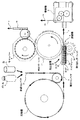
以下、図1につき本発明の第一の実施形態を説明すると、充填機1には供給コンベヤ2よりボトルaを送るようにし、その充填されたボトルaの出口には直線状に延びる容器の搬送間隔を規制して送るドッグチェーン3aを備えた搬出コンベヤ3を設け、その直線状に延びるドッグチェーン3aを備えた搬出コンベヤ3にボトルaのキャッパー4を配置する。
ドッグチェーン3aとキャッパー4との接続部9には、図2示のようにボトルaの取り出しターレット10と受取りターレット11とガイド13、14で構成する、キャッパー4の処理間隔に合わせてボトルaを取り出す取出装置8を設ける。
Hereinafter, a first embodiment of the present invention will be described with reference to FIG. 1. A bottle a is fed from a
As shown in FIG. 2, the connecting portion 9 between the
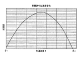
図2示のように、上記取出装置8の取り出しターレット10はそのボトルaを押す部分の形状cを、ボトルaの容器に衝撃を与えないような形状の面、即ち、図5示のように連続した山形の加速度を与えるような曲面にすると共に、その上方には進行方向にむかって受取りターレット11の方に湾曲するガイド13、14を設ける。
As shown in FIG. 2, the take-
次に、取出装置8について説明する。
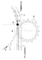
この取出装置8は、図2示のように取り出しターレット10と受取りターレット11とガイド13、14により構成され、接続部9において、図6、図7示のように受取ターレット11はその容器搬送PCD(ピッチサークルダイヤ−ボトルa搬送中心)の接線方向に搬出コンベヤ3のボトルa走行中心が接するように配置し、取り出しターレット10は受取りターレット11のボトル搬送中心が搬出コンベヤ3のボトルa走行中心と接する位置よりもやや充填機1寄りにオフセットしてその対向する側に設置する。
このオフセット量は、図6示のように速度V1 の搬出コンベヤ3のボトルa走行中心に取り出しターレット10の中心に近いポケット中心部分のPCDが回転角度θ1 で接して、進行するにつれて取り出しターレット10の中心より遠い部分に向かってボトルaが移動し、図7示のように回転角度θ2 でそのボトルaを押す部分の形状cの速度V2 となる点に達すると同時に、搬出コンベヤ3のボトルa走行中心と接する位置にある速度V2 の受取りターレット11のポケットのボトルを押す部分に接するように配置する。
取り出しターレット10のボトルaを押す部分の形状cは、ボトルaに衝撃を与えないような形状の面、即ち、図5示のように、連続した加速度を与え、且つ、回転角度θ1 、θ2 で加速度が略0となるような曲面にする。
進行方向にむかって受取りターレット11の方に湾曲するガイド13、14は、回転角度θ1 から回転角度θ2 までの間は直線状に延び、ボトルaが搬出コンベヤ3のボトルa走行中心を進行するにつれて取り出しターレット10のボトルaを押す部分の形状cに接する位置を規制すると共に、回転角度θ2 即ち受取りターレット11の容器搬送PCDが搬出コンベヤ3のボトルa走行中心と接する位置より先は、ボトルが受取りターレット11のポケットのPCDに従ってボトルaが搬送されるように規制する円弧で湾曲している。
Next, the take-out
As shown in FIG. 2, the take-
Extraction turret As this offset amount is PCD central pocket center portion close to the
The shape c of the portion that pushes the bottle a of the take-out
The
尚、充填機1の出口において、直線状に延びるドッグチェーン3aを備えた搬出コンベヤ3への容器受け渡しにおいては、特開2001−122433号公報で開示されている円軌道から直線軌道に円形断面容器を変速して受渡しする搬送方法等、衝撃無く移載するのに好適な搬送方法を採用することが好ましい。
また、前記取り出しターレット10はそのボトルaを押す部分の形状cを、特開2001−122433号公報で開示されている、円軌道から直線軌道に円形断面容器を変速して受渡しする搬送方法を転用して求めることも可能である。
In the delivery of the container to the carry-out
Further, the take-out
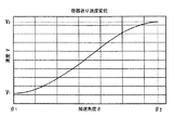
次にこの装置の動作を説明する。図2示のように供給コンベヤ2より供給され充填機1で充填されたボトルaはその出口よりドッグチェーン3aに送られ、接続部9において取り出しターレット10と受取りターレット11とにより取り出されてキャッパー4に送られる。この際、図6、図7示のようにボトルaはガイド13、14により、先ず取り出しターレット10の回転角度θ1 で取り出しターレット10の中心に近い部分に接して遅い速度V1 で送られ、進行するにつれて取り出しターレット10の回転角度θ2 で取り出しターレット10の中心より遠い部分に接して図4示のように速度V1 から速度V2 まで加速して徐々に間隔が開き、キャッパー4の送りピッチに合わされるものである。尚、その際ボトルaを押す部分の形状cにより図5示のように連続し且つ回転角度θ1 、θ2 で加速度が略0となるように送られる。
かくしてボトルaは受取ターレット11により、キャッパー4に送られ、キャップがねじ込まれたりあるいはキャップがボトルaの口部のらせんに成形されてコンベヤ15より送り出される。
Next, the operation of this apparatus will be described. As shown in FIG. 2, the bottle a supplied from the
Thus, the bottle a is sent to the
以上、本発明の第一の実施形態により、充填機1の出口に直線状に延びるドッグチェーン3aを備えた搬出コンベヤ3を設け、その直線状に延びるドッグチェーン3aを備えた搬出コンベヤ3にボトルaのキャッパー4を配置する実施例を説明したが、本発明を応用することで、一台の充填機に複数台のキャッパまたはシーマーを接続することが可能となる。
As described above, according to the first embodiment of the present invention, the
以下、図1につき本発明の第二の実施形態を説明すると、充填機1には供給コンベヤ2よりボトルa、あるいは缶bを送るようにし、その充填されたボトルa、あるいは缶bの出口には直線状に延びるドッグチェーン3aを設け、そのドッグチェーン3aを備えた搬出コンベヤ3の途中にボトルaのキャッパー4を配置し、また、ドッグチェーン3aを備えた搬出コンベヤ3の終端には缶bの蓋の巻締機5を配置する。
Hereinafter, a second embodiment of the present invention will be described with reference to FIG. 1. A bottle a or can b is fed from a
ドッグチェーン3aとキャッパー4との間の分岐部となる接続部9には、図3示のようにボトルaの取り出しターレット10と受取りターレット11とを設ける。上記取り出しターレット10はドッグチェーン3aに対し係合離脱自在に設ける。
As shown in FIG. 3, a take-out
図2示のように、上記取り出しターレット10はそのボトルaを押す部分の形状cを、ボトルaの容器に衝撃を与えないような形状の面、即ち、図5示のように連続した加速度を与え且つ回転角度θ1 、θ2 で加速度が略0となるような曲面にすると共に、その上方には進行方向にむかって受取りターレット11の方に湾曲するガイド13、14を設け、取出装置8を構成する。
尚、この場合、ドッグチェーン3aのピッチは、終端に配置する缶bの蓋の巻締機5が要求する搬送ピッチに合わせることが望ましいが、終端に配置する缶bの蓋の巻締機5にもこの取出装置8を採用すれば、その限りではない。
As shown in FIG. 2, the take-out
In this case, it is desirable that the pitch of the
次にこの装置の動作を説明する。供給コンベヤ2よりボトルaを供給したときには、図2示のように上記取り出しターレット10はドッグチェーン3aに対し係合させる。これにより充填機1で充填されたボトルaはその出口よりドッグチェーン3aに送られ、分岐部となる接続部9において取り出しターレット10と受取りターレット11とにより取り出されてキャッパー4に送られる。この際、図6、図7示のようにボトルaはガイド13、14により、先ず取り出しターレット10の回転角度θ1 で取り出しターレット10の中心に近い部分に接して遅い速度V1 で送られ、進行するにつれて取り出しターレット10の回転角度θ2 で取り出しターレット10の中心より遠い部分に接して図4示のように速度V1 から速度V2 まで加速して徐々に間隔が開き、キャッパー4の送りピッチに合わされるものである。尚、その際ボトルaを押す部分の形状cにより図5示のように連続し且つ回転角度θ1 、θ2 で加速度が略0となるように送られる。
かくしてボトルaは受取ターレット11により、キャッパー4に送られ、キャップがねじ込まれたりあるいはキャップがボトルaの口部のらせんに成形されてコンベヤ15より送り出される。
Next, the operation of this apparatus will be described. When the bottle a is supplied from the
Thus, the bottle a is sent to the
供給コンベヤ2より缶bを供給したときには、上記取り出しターレット10及びガイド14はドッグチェーン3aに対し離脱させる。これにより充填機1で充填された缶bはその出口よりドッグチェーン3aに送られ、分岐部となる接続部9を通過して、缶bの蓋の巻締機5に送られ、製品となってコンベヤ15より送り出される。
When the can b is supplied from the
尚、上記第二の実施形態では、キャッパー4をドッグチェーン3aの途中に設け、巻締機5を終端に配置しているが、上記キャッパー4と巻締機5とは反対に配置してもよい。また、ボトルaと缶bのみならず、サイズの異なる缶、あるいはサイズの異なるボトルを処理する場合には、両方とも口径の異なった巻締機5・・・あるいはキャッパー4・・・とする。
In the second embodiment, the
本発明は、有効且つ効果的なボトルあるいは缶の充填装置の容器の蓋締装置及びその搬送装置を提供できる。 INDUSTRIAL APPLICABILITY The present invention can provide an effective and effective bottle lid closing device for a bottle or can filling device and a transport device for the device.
a ボトル
b 缶
c 取り出しターレットのボトル又は缶を押す部分の形状
1 充填機
2 供給コンベヤ
3 搬出コンベヤ
3a ドッグチェーン
4 キャッパー
5 巻締機
8 取出装置
9 接続部
10 取り出しターレット
11 受取りターレット
13 ガイド
14 ガイド
a Bottle b Can c Shape of the portion of the take-out turret that pushes the bottle or can 1
Claims (3)
Priority Applications (1)
| Application Number | Priority Date | Filing Date | Title |
|---|---|---|---|
| JP2003382417A JP4252425B2 (en) | 2003-11-12 | 2003-11-12 | Container lid clamping device and its conveying device |
Applications Claiming Priority (1)
| Application Number | Priority Date | Filing Date | Title |
|---|---|---|---|
| JP2003382417A JP4252425B2 (en) | 2003-11-12 | 2003-11-12 | Container lid clamping device and its conveying device |
Publications (2)
| Publication Number | Publication Date |
|---|---|
| JP2005145478A JP2005145478A (en) | 2005-06-09 |
| JP4252425B2 true JP4252425B2 (en) | 2009-04-08 |
Family
ID=34691499
Family Applications (1)
| Application Number | Title | Priority Date | Filing Date |
|---|---|---|---|
| JP2003382417A Expired - Lifetime JP4252425B2 (en) | 2003-11-12 | 2003-11-12 | Container lid clamping device and its conveying device |
Country Status (1)
| Country | Link |
|---|---|
| JP (1) | JP4252425B2 (en) |
Families Citing this family (7)
| Publication number | Priority date | Publication date | Assignee | Title |
|---|---|---|---|---|
| CN103771310A (en) * | 2012-10-23 | 2014-05-07 | 江苏柯本机电工具有限公司 | Cover screwing system |
| JP6716858B2 (en) * | 2015-01-15 | 2020-07-01 | 東洋製罐株式会社 | Filling and winding device and filling and winding method for can body |
| CN105984827B (en) * | 2015-02-10 | 2018-07-20 | 上海派协包装机械有限公司 | A kind of full-automatic filling pipeline of electronics tobacco tar |
| CN105271090A (en) * | 2015-11-04 | 2016-01-27 | 长沙今朝科技股份有限公司 | Packing equipment, filling machine, bottle conveying device and adjusting distance poking wheel thereof |
| CN108082618A (en) * | 2017-12-06 | 2018-05-29 | 广州华研制药设备有限公司 | Soft bottle input unit |
| JP7394700B2 (en) * | 2020-05-22 | 2023-12-08 | 東洋製罐グループエンジニアリング株式会社 | Container transport mechanism |
| WO2021235013A1 (en) * | 2020-05-22 | 2021-11-25 | 東洋製罐グループエンジニアリング株式会社 | Pitch measuring mechanism |
-
2003
- 2003-11-12 JP JP2003382417A patent/JP4252425B2/en not_active Expired - Lifetime
Also Published As
| Publication number | Publication date |
|---|---|
| JP2005145478A (en) | 2005-06-09 |
Similar Documents
| Publication | Publication Date | Title |
|---|---|---|
| US8474601B2 (en) | Container transfer device having a transfer guiding member | |
| CN105050924B (en) | Orientation equipment and method | |
| US10519018B2 (en) | Receptacle handling apparatus for filing and capping receptacles | |
| US9073695B2 (en) | Asymmetric article handling and orientation | |
| JP4252425B2 (en) | Container lid clamping device and its conveying device | |
| JP4232265B2 (en) | Resin bottle transfer processing system | |
| CN113454005B (en) | Transport facility for containers | |
| WO2004074144A8 (en) | Star-shaped conveyor for feeding or discharging empty plastics containers or bottles to or from a machine and orienting and aligning machine having said star-shaped conveyor | |
| JP4951767B2 (en) | Beverage container holding device and beverage container delivery / conveying device using the holding device | |
| JP4252424B2 (en) | Container filling lid clamping device | |
| JP6424511B2 (en) | Method of conveying articles and apparatus therefor | |
| JP2020015581A (en) | Conveyance device of square-shaped article | |
| US4114774A (en) | Closure cap | |
| AU6676598A (en) | Orienting apparatus for an orientationally sensitive closure | |
| JP4967300B2 (en) | container | |
| CN107223111A (en) | For the apparatus and method for making container flow slow down in container treatment facility | |
| CN101959775B (en) | Cap transfer unit having movable cap pusher | |
| CN112978656B (en) | Device for introducing or removing containers and container treatment device | |
| JP2000289847A (en) | Carrier device of resin bottle | |
| JP2000289832A (en) | Carrier device of resin bottle | |
| EP4442636B1 (en) | Machine for capping containers | |
| US20070131519A1 (en) | Device for feeding corks to an automatic corking machine | |
| JP2008505825A (en) | Apparatus for supplying a pouch and a mouthpiece of each pouch to the rotating machine for processing, and a method related thereto | |
| JP7659196B2 (en) | Container Processing Equipment | |
| EP0006019A1 (en) | Plant for the filling of containers with quantities of liquid |
Legal Events
| Date | Code | Title | Description |
|---|---|---|---|
| A621 | Written request for application examination |
Free format text: JAPANESE INTERMEDIATE CODE: A621 Effective date: 20060607 |
|
| A977 | Report on retrieval |
Free format text: JAPANESE INTERMEDIATE CODE: A971007 Effective date: 20080922 |
|
| A131 | Notification of reasons for refusal |
Free format text: JAPANESE INTERMEDIATE CODE: A131 Effective date: 20080930 |
|
| A521 | Request for written amendment filed |
Free format text: JAPANESE INTERMEDIATE CODE: A523 Effective date: 20081201 |
|
| TRDD | Decision of grant or rejection written | ||
| A01 | Written decision to grant a patent or to grant a registration (utility model) |
Free format text: JAPANESE INTERMEDIATE CODE: A01 Effective date: 20090120 |
|
| A01 | Written decision to grant a patent or to grant a registration (utility model) |
Free format text: JAPANESE INTERMEDIATE CODE: A01 |
|
| A61 | First payment of annual fees (during grant procedure) |
Free format text: JAPANESE INTERMEDIATE CODE: A61 Effective date: 20090121 |
|
| R150 | Certificate of patent or registration of utility model |
Ref document number: 4252425 Country of ref document: JP Free format text: JAPANESE INTERMEDIATE CODE: R150 Free format text: JAPANESE INTERMEDIATE CODE: R150 |
|
| FPAY | Renewal fee payment (event date is renewal date of database) |
Free format text: PAYMENT UNTIL: 20120130 Year of fee payment: 3 |
|
| FPAY | Renewal fee payment (event date is renewal date of database) |
Free format text: PAYMENT UNTIL: 20130130 Year of fee payment: 4 |
|
| R250 | Receipt of annual fees |
Free format text: JAPANESE INTERMEDIATE CODE: R250 |
|
| FPAY | Renewal fee payment (event date is renewal date of database) |
Free format text: PAYMENT UNTIL: 20140130 Year of fee payment: 5 |
|
| EXPY | Cancellation because of completion of term |