JP4250291B2 - Image processing apparatus, image processing method, and storage medium - Google Patents
Image processing apparatus, image processing method, and storage medium Download PDFInfo
- Publication number
- JP4250291B2 JP4250291B2 JP2000021562A JP2000021562A JP4250291B2 JP 4250291 B2 JP4250291 B2 JP 4250291B2 JP 2000021562 A JP2000021562 A JP 2000021562A JP 2000021562 A JP2000021562 A JP 2000021562A JP 4250291 B2 JP4250291 B2 JP 4250291B2
- Authority
- JP
- Japan
- Prior art keywords
- image
- input
- sub
- processing
- determination
- Prior art date
- Legal status (The legal status is an assumption and is not a legal conclusion. Google has not performed a legal analysis and makes no representation as to the accuracy of the status listed.)
- Expired - Fee Related
Links
- 238000003672 processing method Methods 0.000 title claims description 9
- 238000000034 method Methods 0.000 claims description 55
- 238000000605 extraction Methods 0.000 claims description 26
- 238000007639 printing Methods 0.000 description 16
- 238000010586 diagram Methods 0.000 description 15
- 238000004891 communication Methods 0.000 description 5
- 238000001514 detection method Methods 0.000 description 5
- 239000000976 ink Substances 0.000 description 5
- 239000000463 material Substances 0.000 description 3
- 238000009826 distribution Methods 0.000 description 2
- 230000000694 effects Effects 0.000 description 2
- 238000005516 engineering process Methods 0.000 description 2
- 230000002265 prevention Effects 0.000 description 2
- 239000003086 colorant Substances 0.000 description 1
- 230000006835 compression Effects 0.000 description 1
- 238000007906 compression Methods 0.000 description 1
- 238000009792 diffusion process Methods 0.000 description 1
- 238000011156 evaluation Methods 0.000 description 1
- 210000003128 head Anatomy 0.000 description 1
- 230000001771 impaired effect Effects 0.000 description 1
- 230000003287 optical effect Effects 0.000 description 1
- 238000000926 separation method Methods 0.000 description 1
- 239000007787 solid Substances 0.000 description 1
- 238000001228 spectrum Methods 0.000 description 1
Images


Description
【0001】
【発明の属する技術分野】
本発明は画像処理装置及び画像処理方法及び記憶媒体に関する。
【0002】
【従来の技術】
近年カラーコピー機には紙幣や有価証券等の偽造防止用の画像認識処理機能等を搭載することが提案されている。複写物生成の対象画像データが偽造防止対象画像であると判定される場合には、その画像データに対しては、(1)何らかの色彩で塗り潰してプリント出力する、(2)何らかの記号や図形を重畳してプリント出力する、(3)色彩や画像サイズを変更して出力する、(4)プリント出力を全くしない、等のように正常な複写出力が行われないようにするというものである。
【0003】
ところで複写機は、紙幣等の複写禁止物を除き原稿台上に載置された物体を忠実に複写することが原則であるため、仮に紙幣に似た画像(紙幣ではなく、法律的にも複写可能な画像)が入力された場合には、紙幣ではないと認識してそのままの複写処理を行なう必要がある。このため、認識対象の画像が偽造防止対象画像に該当するか否かの判定は、極めて厳密な認識精度が要求される。
【0004】
一方、昨今では、カラーコピー機に比して廉価なカラースキャナやカラープリンタにより得られる画像の画質も飛躍的に向上しており、これらの機器をパソコンに接続して、いわばカラーコピー機の要素機器の組合せ使用によっても、同様な偽造行為が可能となってきている。このため、廉価なカラースキャナやカラープリンタを用いる画像処理システムにおいても画像認識処理機能の搭載等による紙幣や有価証券等の偽造防止対策が望まれてきている。
【0005】
尚、原稿が複写禁止対象物であるか否かの判定法方としては、画像データ中の各画素値(三色カラー信号に対応する R,G,Bの値のセット)に基いて、原稿をスキャンして得られる画像データのカラースペクトル分布をROM13に予め登録してあるデータと比較したり(違いを数値間の差分値の絶対値の総和として求めたり、分布間の相互相関値を算出したり等)、あるいは、原稿の一部あるいは全体の総合的な画像パターンをROM等に予め登録してあるパターンデータと比較したりすることで評価値を算出する方法等が提案されている。
【0006】
また、最近では、"電子透かし"と呼ばれる技術を用いることにより、印刷物としての原稿内に複写禁止対象物であることを示す情報を含ませて作成しておく事も可能となってきている。即ち、複写禁止対象物である原稿を、その原稿が印刷物として作成される際に、予め、元になる第一のディジタル情報(主情報)である画像データ(電子的な画像情報)に対して、複写禁止対象物であることを示す第二のディジタル情報(副情報)を埋め込むことにより生成された複写禁止対象物情報の入りの画像データ(やはり電子的な画像情報)から印刷物として作成しておく方法である。この複写禁止対象物情報(副情報)は、原稿を印刷する前の複写禁止対象物情報の入りの画像データから抽出できることはもちろんのこと(電子透かし技術そのもの)、複写禁止対象物情報の入りの画像データ(電子的な画像情報)から印刷物として作成した時の条件と読み取りや抽出処理の条件の整合性を取れば、それを含んだ電子的な画像情報から作成された印刷物(原稿)をカラースキャナ等の原稿読取装置により読み取って得られる電子的な画像データから抽出することも可能であることから、この"電子透かし"と呼ばれる技術の、印刷物としての原稿の違法な複製を防ぐ用途への適用が着目される始めている。
【0007】
【発明が解決しようとする課題】
コンシューマ市場で一般的に用いられる廉価なカラースキャナやカラープリンタにおいては、比較的高価なカラー複写機に比して、より安価に複写禁止対象物の偽造防止の実現を図ることが望ましい。そのためには、複写禁止対象物の認識処理機能を電子回路等を多用したハードウェア主体の実現方法によらず、なるべくソフトウェア主体の実現方法をとることが有力な解となり得る。
【0008】
反面、ソフトウェア主体の実現方法によって先に述べた様な厳密な認識精度を要求される複写禁止対象画像の判定を行なおうとすると、演算の総量が多い以上、その認識・判定に要する処理時間が著しく長くなりがちであるという問題がある。
【0009】
裏返せば、認識・判定にかける演算量を減らそうとすると、一般的には、厳密な認識精度を要求される複写禁止対象画像の判定の実現が難しくなる傾向にあり、故意に読み取り条件(原稿の読み取り面上での置載角度、置載位置等)を変更して読み込まれた画像からの紙幣等の複写禁止物の検出等が難しくなったり、あるいは逆に、紙幣に似た画像(紙幣ではなく、法律的にも複写可能な画像)が入力された場合でも、複写禁止対象画像であると誤認識して、正常な出力を行なわずに、本来の画像処理システムとしての機能を損なってしまう、等の恐れがある。
【0010】
本発明は、上述した従来の問題点に鑑みてなされたものであり、その目的とするところは、安価なイメージスキャナやカラープリンタを使用したパソコンシステムにおいて、比較的少ない演算量の認識・判定処理でも、従来に比し、より厳密な複写禁止対象物か否かの認識を可能とする画像処理システムを構成する画像処理装置、画像処理方法、及び、記憶媒体を提供することにある。
【0011】
【課題を解決するための手段】
上記課題を解決するために本発明は、入力される画像から所定のサイズを有するバンド領域の画像情報を入力する入力手段と、前記バンド領域から所定サイズを有するサブブロックの画像情報を選定するサブブロック選定手段と、前記サブブロックの画像情報から、一定周期で埋め込まれている電子透かしの抽出を行い、前記入力される画像が予め定められた特徴を有する特定画像であるか否かを判定する特定画像判定手段と、前記特定画像判定手段による判定結果に応じて、前記入力される画像に対する処理を行なう処理手段とを有し、前記サブブロック選定手段は、ランダム位置に配置されるサブブロックを選定し、前記特定画像判定手段は、前記サブブロックに対してのみ電子透かしの抽出処理を行うことを特徴とする。
【0012】
【発明の実施の形態】
(第一の実施の形態)
以下、この発明の好ましい実施の形態の一例として、原稿内に含まれる複写禁止対象物であることを示す情報が、"電子透かし"と呼ばれる技術により作成されている場合に基いて説明をすすめる。即ち、複写禁止対象物である原稿が、印刷物として作成される元になる第一のディジタル情報である画像データ(電子的な画像情報)に対して、複写禁止対象物であることを示す第二のディジタル情報を埋め込むことにより生成された複写禁止対象物情報の入りの画像データ(やはり電子的な画像情報)から印刷物として作成されている事を前提として説明をすすめる。尚、上述した電子透かしは、画像データの特定空間周波数に情報をうめ込む不可視の電子透かし、人の目に見えにくいイエロー(系)ドットの配列により情報をうめ込む可視の電子透かし等どの様なものでもよい。
【0013】
先に述べたように、電子透かし技術により埋め込まれた電子透かしデータを抽出するためには、一般的に読み取りや抽出の条件を、透かし情報を埋め込んだ印刷物を生成した際の条件(即ち、画像データのどの位置にどのような並びで埋め込まれているか等)に整合性が取れるようにする必要がある。
【0014】
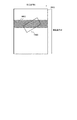
図1は複写禁止対象物の一種である紙幣である。0101は紙幣全体を示し、0102の領域には紙幣の偽造紙幣を判別するための透かしが埋め込まれている。
【0015】
今、複写禁止対象物であるか否かを判別する情報が、紙幣全体0101に電子透かし技術を用いて埋め込まれていることとする。
【0016】
図2は第1の実施例で複写禁止対象物の抽出が想定される環境である。
【0017】
同図において、0201は画像入力装置としてのカラーイメージスキャナ、0202はコンピュータシステムとしてのパソコン、0203はカラーイメージスキャナ0201とコンピュータシステム0202間でのデータのやり取りをするための接続ケーブルを表している。
【0018】
図3は、図2の構成における主要部を機能モジュールとしてのブロックにより表現したブロック図である。同図において、0311はCPU、0312はRAM、0313はROM、0314はディスプレイ制御部、0315はディスプレイ、0316はキーボードやマウスなどの操作入力、0317はデバイスキーボードやマウスなどの操作入力デバイスの接続I/O、0318はハードディスク装置などの外部記憶装置、0319は外部記憶装置の接続I/O、0320はバス、0321はカラーイメージスキャナ、0322はカラーイメージスキャナなどの画像入力機器との接続I/Oである。0323はネットワークなどの通信手段とのインターフェース部である。
【0019】
本第1の実施の形態では複写禁止対象物がカラーイメージスキャナを通じて入力される場合に、複写禁止対象物であるか否かを判断し、複写禁止対象物であると判断された場合には、画像入力を停止し、そうでないと判断された場合には、画像入力を続行するシステムを提案する。
【0020】
図5は図2および図3に示した構成上で、処理を実施するための動作手順を示すフローチャートである。図5のフローチャートに示す手順を記述したコンピュータ実行可能なプログラムを、あらかじめROM0313に格納しておき、あるいは、あらかじめ外部記憶装置0319に格納されているプログラムをRAM0312上の読みこんだ後にCPU0311により該プログラムを実行(ソフトウエア処理)することにより処理を実施する。この場合前述のプログラムはスキャナドライバである。
【0021】
はじめにイメージスキャナ0201が行う画像取りこみの仕組みについて説明する。ここではイメージスキャナ0201はコンシューマ市場で最も一般的であるフラッドベッドスキャナを例にとり説明を行う。なお、その他の種類のスキャナでも本実施の形態で適用することが可能であることは、後の説明により自明である。
【0022】
図4に示すイメージスキャナの原稿台0401に置かれた原稿に対し、イメージスキャナ内部にある光源が、主走査方向0402の一列の原稿を照らし出す。原稿で反射した光は、内部にあるミラー、およびレンズを経てCCDセンサに入力する。CCDセンサは光の強度を数値データに変更し、横一列分の読み取り(主走査)が完了する。この後、ミラーと光源が副走査方向0403に少しづつ移動して、同じ走査を繰り返す。このように原稿の横方向(主走査方向0402)の情報を読み取ることを縦方向の回数分繰り返すことで、原稿全体の読みこみが行われる。
【0023】
本実施の形態1においては、イメージスキャナ0321は、上述の走査を繰り返し、接続I/O 0322を通じて、RAM0312内部に画像情報を蓄積する。コンピュータ0202内部では、CCDセンサの移動方向(主走査方向)の長さを持ち、光源とミラーの移動方向(副走査方向)に一定の幅を持つバンド領域0404の入力がRAM0312へ行われるたびに、CPU0313でプログラムを動かすことにより電子透かし情報の抽出を行うとする。
【0024】
図5はその一連の処理をフローチャートにて記したものである。スキャンが開始されると、イメージスキャナはステップ0502にて主走査方向へのスキャンを行う。その後またはそれと並行し、ステップ0503で接続I/O 0322を通じてRAM0312へ画像情報の転送を行う。ステップ0504ではRAM0312内部に新たにバンド領域に相当する画像情報の入力が行われたかを判定する。
【0025】
ステップ0504でバンド領域に相当する画像情報が入力された場合には、ステップ0510に進み、バンド領域内からさらに電子透かしを抽出するサブブロックを選定し、ステップ0505に進み、ステップ0510で選定したサブブロックから電子透かしの抽出処理を行う。
【0026】
このサブブロックを選定するサブブロック選定手段については、後ほど詳しく説明する。
【0027】
ステップ0504でバンド領域に相当する画像情報が入力されていない場合には、ステップ0506に進み、さらに副走査方向へ進みスキャンする必要があるか(原稿台全体に対するスキャンが終了したか)を判断する。
【0028】
ステップ0506でさらに副走査方向へ進みスキャンする必要がない場合にはステップ0509に進み、スキャンを終了する。さらに副走査方向へ進みスキャンする必要がある場合にはステップ0508に進み、副走査方向への移動を行い、ステップ0502に戻る。
【0029】
ステップ0505で電子透かしの抽出処理を行い、複写禁止対象物であるとの電子透かし情報が抽出された場合には、ステップ0507に進み、直ちに今までRAM0312へ入力された画像情報を破棄し、スキャンを終了する。
【0030】
ステップ0505で電子透かしの抽出処理を行い、複写禁止対象物でないと判断した場合には、ステップ0506に進み、原稿のスキャンが終了した場合には、ステップ0509に進みスキャンを終了する。
【0031】
ステップ0506で原稿のスキャンが終了していないと判断される場合にはステップ0508に進み、副走査方向へ光源を移動し、ステップ0502に戻る。
【0032】
以上の一連の処理により、カラーイメージスキャナを用いて画像の入力を行いつつ、同時に複写禁止対象物であるか否かを判断し、複写禁止対象物である場合には処理を中止することが可能になる。
【0033】
次に、ステップ0510における電子透かしの抽出処理を行う領域を選定するサブブロック選定手段について詳しく述べる。
【0034】
図6は複写禁止対象物0603がイメージスキャナの原稿台0601に置かれ、画像情報を読みとっている様子を示した図である。なお、複写禁止対象物0603の全面には、複写禁止であることを表す情報が電子透かし技術を用いて埋め込まれている。尚、複写禁止対象物0603には一定周期に電子透かしがうめ込まれている。0602は複写禁止対象物か否かの判断を行うためのバンド領域を示し、バンド領域の容量を満たす画像情報が新たに入力されるたびに、図3のRAM0312に蓄えられたバンド領域の画像情報は、CPU0311により電子透かしの抽出処理が行われる。
【0035】
通常、厳密に複写禁止対象物であるか否かの判断を行う場合、電子透かしの抽出処理を行うバンド領域0602の画像情報全てに対して抽出処理を行うのが、もっとも確実な方法である。
【0036】
しかし、実際には電子透かしの抽出処理を全てのバンド領域の画像情報に対して行った場合、電子すかし抽出処理における処理が終わるまで光源ミラーの副走査方向に対する移動が行われないため画像のスキャン速度の低下が起こることが予想される。
【0037】
本実施の形態では、厳密に複写禁止対象物であるか否かの判断を行ないつつ、画像のスキャン速度をできるかぎり低下させない方法を提案する。
【0038】
図7は電子透かしの抽出処理を行うバンド領域中において、電子透かしの抽出対象領域として市松模様にサブブロックを設定し、このサブブロックのみを抽出処理(電子すかし判定)する場合を示している。市松模様を形成するサブブロック0702は、電子透かしの抽出が行える最低限の大きさを有することが好ましい。サブブロック0702は、電子透かしの方式、サイズによりそのサイズが異なることが考えられるが、複写禁止対象物中に十分な数だけ含まれると考えられる。
【0039】
図7のように複写禁止対象物0703が傾けられ、入力された場合にも、複写禁止対象物0703から電子透かしの抽出に必要なサブブロックが得られ、複写禁止対象物であるか否かの判断が有効に行えることが分かる。この様にサブブロックに対してのみ電子すかしの抽出処理を行うことでソフトウエアにて抽出処理する際の処理時間の削減を実現できる。
【0040】
電子透かし抽出バンド領域において、サブブロックを市松模様に選択するのみならず、分散させて配置させ、選択する場合にも同様に効果が得られる。
【0041】
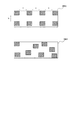
次にサブブロックを分散させて配置する例について述べる。図8の0801は、サブブロックの配置方法を主走査方向に一定間隔a、副走査方向に一定間隔bで配置した場合の例である。また0802は、サブブロックの配置をランダム位置に配置した場合である。どちらの方法も複写禁止対象物が傾けられて、イメージスキャナの原稿台に置かれていた場合にも有効であることが分かる。
【0042】
上記方法に限らず、抽出したい電子すかしに合わせて、その電子すかしの抽出に好適となる様電子透かしの抽出を行うサブブロックを分散させて配置することにより、複写禁止対象物であるか否かの判断を行い、その判断に基づきスキャンを制御するとともに、同時にスキャン速度の低下をできるだけ防ぐ種々の方法は本実施の形態に含まれるものである。
【0043】
以上の様に本実施の形態によれば、ブロックからサブブロックを選定してこのサブブロックに対して電子すかし抽出を行うので、ブロック全体に電子すかしの抽出を行うものに比べ高速に電子すかし抽出が可能となる。
【0044】
又、予め複写禁止対象物へうめ込まれている電子透かしのうめ込み間隔を考慮して本実施の形態では複写禁止対象物の位置/向きによらずこの電子透かしを必ず1つは抽出できる様に、サブブロックを設定するものである。そのための種々のサブブロックの設定は本実施形態に含まれる。
【0045】
(第2の実施の形態)
前記第1の実施の形態においては、カラーイメージスキャナより読み込んだ画像に関して、複写禁止対象物であるか否かの判断を電子透かし技術を用いてチェックすることを前提に説明した。
【0046】
しかし、複写禁止対象物の入力は必ずしもカラーイメージスキャナより読み込んだカラー画像に限るものではなく、例えば、図3の0323に示されるネットワークなどの通信手段とのインターフェース部を介して入手したり、あるいは、着脱可能な記憶媒体(例えば、スマートメディアやコンパクトフラッシュ、もしくは、光磁気ディスクなど)を図示しない当該画像処理システムに接続される、それ用の駆動装置に装着することによって、その着脱可能な記憶媒体上に保持されるカラー画像データを取り込むことによって得られる場合も考えられる。この場合、ネットワーク等の通信手段を実現するプログラム(例えば、インターネットプラウザソフト)、記憶媒体から画像を獲得するプログラムに上述の複写禁止対象物特徴チェックプログラムが含まれる。
【0047】
図9は第2の実施の形態で複写禁止対象物の抽出が想定される環境である。
【0048】
同図において、0903は画像入力装置としてのカラーイメージスキャナ、0901はコンピュータシステムとしてのパソコン、0907はカラーイメージスキャナ0903とコンピュータシステム0901間でのデータのやり取りをするための接続ケーブル、0902は画像出力装置としてのカラープリンタ、0908はカラープリンタ0902とコンピュータシステム0901間でのデータのやり取りをするための接続ケーブル、0904はCD−ROMに代表される着脱可能な外部記憶媒体、0905はLANやインターネットに代表されるネットワーク、0906はコンピュータシステムとLANやインターネット間のデータの通信を行うための接続ケーブルを表している。
【0049】
図10は、図9の構成における主要部を機能モジュールとしてのブロックにより表現したブロック図である。同図において、1011はCPU、1012はRAM、1013はROM、1014はディスプレイ制御部、1015はディスプレイ、1016はキーボードやマウスなどの操作入力、1017はデバイスキーボードやマウスなどの操作入力デバイスの接続I/O、1018はハードディスク装置などの外部記憶装置、1019は外部記憶装置の接続I/O、1020はバス、1021はカラーイメージスキャナ、1022はカラーイメージスキャナなどの画像入力機器との接続I/O、1024はカラープリンタ、1025はカラープリンタなどの画像出力機器との接続I/Oである。1023はネットワークなどの通信手段とのインターフェース部である。
【0050】
本実施の形態2では既にディジタル化された複写禁止対象物が外部記憶媒体やネットワークを通じて入力された場合に、カラープリンタで印刷出力を行う前に、複写禁止対象物であるか否かを判断し、複写禁止対象物であると判断された場合には、印刷出力を停止し、そうでないと判断された場合には、印刷を続行するシステムを提案する。
【0051】
図14は図9および図10に示した構成上で、第2の実施の形態の処理を実施するための動作手順を示すフローチャートである。図4のフローチャートに示す手順を記述したコンピュータ実行可能なプログラムを、あらかじめROM1013に格納しておき、あるいは、あらかじめ外部記憶装置1019に格納されているプログラムをRAM1012上に読みこんだ後にCPU1011により該プログラムを実行することにより第2の実施の形態の処理を実施する。
【0052】
はじめにカラーイメージスキャナ0903、ネットワーク0905、外部記憶装置0904からコンピュータシステム0901に入力される画像データを画像出力装置としてのカラープリンタ0902に出力するための画像処理を行うプリンタドライバの処理について述べる。
【0053】
一般的にカラーディジタル画像は1画素が階調情報をもつ複数の色成分から構成される。例えばRGB24ビットカラー情報の場合、赤、緑、青はそれぞれ8ビット(256階調)の情報をもつため、1画素では24ビット(約1670万色)もの色を表現することが可能である。
【0054】
しかしながら、プリンタ(ここでは主にコンシューマ市場で最も一般的であるインクジェットプリンタについて述べる)はCMYK(シアン、マゼンダ、イエロー、ブラック)の4色インク(またはそれに準じるインク、例えば、うすいシアン、うすいマゼンタ、うすいブラック)により画像を構成し、各インクの出力においては、ONまたはOFFの状態しかなく、インクドットに階調情報を持たせることは難しい。そのため単位面積あたりに打ち出すインクドットの量・数により面積的に画素値の階調を表現する。以上のことからカラー画像のCMYKへの色分解と濃度階調を面積階調へ変換するための2値化処理(ハーフトーン処理)が必要になる。
【0055】
またモニタの色再現域とプリンタの紙上での色再現域は異なるため、人の目に好ましく映るような色空間圧縮(カラーマッチング)もプリンタドライバで行う必要がある。
【0056】
上記に代表されるプリント用の画像処理のため、外部記憶媒体1018またはROM1013に存在する画像データは、RAM1012に展開され、CPU1011で上記の画像処理が行われる。画像処理が行われた結果、プリンタの制御情報が生成され、カラープリンタとの接続I/O1025を通し、カラープリンタ1024に入力される。この一連の画像処理がプリンタドライバの行う処理である。なお、プリンタドライバはあらかじめROM1013または外部記憶装置1019に格納されているプログラムであり、RAM1012上に読み込んだ後にCPU1011により実行される。
【0057】
図11を用いてプリンタドライバの処理を簡単に述べる。画像1101をプリンタで出力する場合には、一度に画像1101全体をRAM1012に展開して処理を行うのではなく、プリンタヘッドの移動方向(主走査方向)の長さを持ち、紙送りの方向(副走査方向)に幅を持つ斜線のバンド領域1103がプリンタドライバの一度の処理単位となる。
【0058】
ただし、2値化処理(ハーフトーン処理)を行う場合に、誤差拡散法など前のラインの情報が必要なときは、別に誤差情報を記憶するバッファ領域を確保しておき、その情報を保存しておく。
【0059】
以上のようにして、プリンタドライバは画像1101を複数個のバンド領域に分けて、RAM1012に展開し、CPU1011において画像処理を行うことにより、画像1101を印刷出力する。
【0060】
本実施の形態では、このプリンタドライバのバンド領域ごとに、複写禁止対象物であるか否かの判断を電子透かし技術を用いて行うことにより、複写禁止対象物のプリンタでの正常な印刷出力を抑止する方法を提案する。
【0061】
図14に本実施の形態における一連の処理のフローチャートを示す。
【0062】
ステップ1401で印刷開始すると、ステップ1402で画像情報をバンド領域分RAM1012への読み込みを行う。ステップ1403ではRAM1012にあるバンド領域から電子透かしの抽出を行うサブブロックの選定を行う。このステップ1403における電子透かしの抽出を行うサブブロックを選定するサブブロック選定手段については、後に詳しく説明を行う。ステップ1404では電子透かしの抽出を行う領域から電子透かしの抽出を行う。電子透かしの抽出を行った結果、複写禁止対象物と判断された場合には、ステップ1408に進み、ただちに印刷出力を中止する。尚、この印刷出力の中止とは、印刷を止める、もしくは、正常な印刷を止める(ベタ画像、網画像の様に忠実な印刷をしない)のいずれでもよい。またこの場合、操作者になぜ正常な印刷が行われないかを知らしめるため“複写禁止画像はプリントできません”等の表示を行わせる。
【0063】
複写禁止対象物ではないと判断された場合にはステップ1405に進み、通常のプリンタドライバ処理を行う。その後ステップ1406に進み、全画像領域の印刷が終了していれば、ステップ1408に進み、印刷を終了し、全画像領域の印刷が終了していなければ、ステップ1407に進み、次のバンド領域に対する処理を行う。
【0064】
図12は複写禁止対象物1203を含むディジタル画像データ1201をプリンタ0902で出力する例を示している。
【0065】
プリンタドライバの処理がバンド領域1202に達するとき、複写禁止対象物1203の一部の領域は、バンド領域1202に含まれるため、電子透かし抽出処理により、複写禁止対象物であることを判定することが可能である。
【0066】
しかしながら、バンド領域1202全体から電子透かし抽出処理を行う場合、プリンタドライバの処理速度が大幅に低下することが考えられる。
【0067】
したがって、ステップ1403のサブブロック選定手段においては、本実施の形態においても前記の第1の実施の形態と同様に、バンド領域の中から電子透かしの抽出を行うサブブロックを図13のように市松模様に配置したり、図8の0801に示すように主走査方向に一定間隔aで配置し、副走査方向に一定間隔bで配置したり、図8の0802にようにランダム位置に配置したりする領域から選定することにより、複写禁止対象物であるか否かの判断を行い、その判断に基づき印刷を制御するとともに、同時にプリンタドライバの処理速度の低下をできるだけ妨げることが可能である。
【0068】
上記方法に限らず、抽出したい電子すかしに合せて、その電子すかしの抽出に好適となる様、電子透かしの抽出を行うサブブロックを分散させて配置することにより、複写禁止対象物であるか否かの判断を行い、その判断に基づき印刷を制御するとともに、同時に印刷速度の低下をできるだけ防ぐ種々の方法は本実施の形態に含まれるものである。
【0069】
尚プリント時間が重要なセールスポイントとなるプリンタ(ドライバ)で処理速度の低減を実現できる上述の電子すかしの抽出は好適である。
【0070】
(本発明の他の実施形態)
前述した実施形態の機能を実現するように前述した実施形態の構成を動作させるプログラムを記憶媒体に記憶させ、該記憶媒体に記憶されたプログラムをコードとして読み出し、コンピュータにおいて実行する処理方法も上述の実施形態の範疇に含まれるし、前述のプログラムが記憶された記憶媒体も上述の実施形態に含まれる。
【0071】
かかる記憶媒体としてはたとえばフロッピーディスク、ハードディスク、光ディスク、光磁気ディスク、CD−RON、磁気テープ、不揮発性メモリカード、ROMを用いることができる。
【0072】
また前述の記憶媒体に記憶されたプログラム単体で処理を実行しているものに限られず、他のソフトウエア、拡張ボードの機能と共同して、OS上で動作し前述の実施形態の動作を実行するものも前述した実施形態の範疇に含まれる。
【0073】
【発明の効果】
以上のように本発明によれば、入力される画像から所定のサイズを有するバンド領域の画像情報を入力する入力手段、前記バンド領域から所定サイズを有するのサブブロックの画像情報を選定するサブブロック選定手段、前記サブブロックの画像情報に応じて、前記入力される画像が予め定められた特徴を有する特定画像であるか否かを判定する特定画像判定手段、前記特定画像判定手段による判定結果に応じて、前記入力される画像に対する処理を行なう処理手段とを有するので、比較的少ない演算容量で特定画像判定処理を行なう古都が可能となる。
【0074】
更には、周期的に配置される特徴を抽出しやすいサブブロックを選定できる。
【0075】
また入力される画像の向き/位置が種々の状態であっても特徴を抽出可能に出来る。
【0076】
更には、特手宇画像であると判定した場合、前記入力される画像に対する入力を中止することができ、例えば有価証券に応じた画像のように入力が禁止された画像の不正な入力を防止できる。
【0077】
また前記特定画像判定手段は前記入力される画像の電子透かしを抽出することで、前記入力される画像が前記特定画像であるか判定することで、入力される画像において特定画像を判定するための情報を人の目に見えにくいもしくは見えない情報とすることができ、高いセキュリティーを実現できる。
【0078】
また前記特定画像判定手段による判定結果、前記入力される画像が特定画像と判定された場合、前記入力される画像に対するプリンタドライバの処理を行なわないので、複写禁止画像のプリントを防止することが可能となる。
【0079】
更に、前記特定画像判定手段による判定結果を表示するので、操作者に装置の状態を知らせることが可能となる。
【図面の簡単な説明】
【図1】複写禁止対象物の一例の紙幣を示す図である。
【図2】本発明の実施形態となる画像処理システムの一例を示す図である。
【図3】図2の主要部の構成を示すブロック図である。
【図4】イメージスキャナにおける画像取り込み操作を説明する図である。
【図5】第1の実施例における動作手順を示すフローチャートである。
【図6】第1の実施例における複写禁止対象物の検出を説明する図である。
【図7】第1の実施例における複写禁止対象物の効率的な検出を説明する図である。
【図8】第1の実施例における効率的な複写禁止対象物の検出を行うための検出領域を示す図である。
【図9】本発明の実施形態となる画像処理システムの一例を示す図である。
【図10】図9の主要部の構成を示すブロック図である。
【図11】プリンタドライバの画像処理を説明する図である。
【図12】第2の実施例における複写禁止対象物の検出を説明する図である。
【図13】第2の実施例における複写禁止対象物の効率的な検出を説明する図である。
【図14】第2の実施例における動作手順を示すフローチャートである。[0001]
BACKGROUND OF THE INVENTION
The present invention relates to an image processing apparatus, an image processing method, and a storage medium.
[0002]
[Prior art]
In recent years, it has been proposed that a color copier is equipped with an image recognition processing function for preventing counterfeiting of banknotes and securities. If it is determined that the copy generation target image data is a forgery prevention target image, the image data is (1) painted in some color and printed out. (2) Some symbol or figure is printed. For example, (3) output by changing the color or image size, (4) no print output, or the like to prevent normal copy output from being performed.
[0003]
By the way, because the principle of copying machines is to faithfully copy objects placed on the document table except for prohibited items such as banknotes, images that resemble banknotes (legal copies, not banknotes). When a possible image) is input, it is necessary to recognize that it is not a banknote and perform the copying process as it is. For this reason, a very strict recognition accuracy is required to determine whether an image to be recognized corresponds to an image for preventing forgery.
[0004]
On the other hand, in recent years, the image quality of images obtained by cheaper color scanners and color printers has been dramatically improved compared to color copiers. Similar counterfeiting has become possible through the combined use of devices. For this reason, even in an image processing system using an inexpensive color scanner or color printer, measures for preventing counterfeiting of banknotes and securities by mounting an image recognition processing function have been desired.
[0005]
As a method for determining whether or not a document is a copy-prohibited object, the document is based on each pixel value in the image data (a set of R, G, and B values corresponding to a three-color color signal). Compare the color spectrum distribution of the image data obtained by scanning the image data with the data registered in ROM13 in advance (calculate the difference as the sum of the absolute values of the difference values between the numerical values, or calculate the cross-correlation value between the distributions) Or a method for calculating an evaluation value by comparing a total image pattern of a part or the whole of a document with pattern data registered in advance in a ROM or the like.
[0006]
Recently, by using a technique called “digital watermark”, it has become possible to create a document including information indicating that it is a copy-prohibited object in a document as a printed material. That is, when an original that is a copy-prohibited object is created as a printed matter, the image data (electronic image information) that is the original first digital information (main information) is preliminarily created. A copy is created from the image data (also electronic image information) containing the copy prohibited object information generated by embedding the second digital information (sub-information) indicating that the object is a copy prohibited object. It is a method. This copy-prohibited object information (sub-information) can be extracted from the image data containing the copy-prohibited object information before printing the original (digital watermark technology itself), and the copy-prohibited object information If consistency between the conditions when the printed data is created from the image data (electronic image information) and the conditions of the reading and extracting process are consistent, the printed material (original) created from the electronic image information including the conditions is color. Since it is also possible to extract from electronic image data obtained by reading with a document reading device such as a scanner, this technique called “digital watermark” is used for preventing illegal copying of a document as a printed matter. Application has begun to attract attention.
[0007]
[Problems to be solved by the invention]
In inexpensive color scanners and color printers generally used in the consumer market, it is desirable to realize counterfeit prevention of copy-prohibited objects at a lower cost than relatively expensive color copiers. To that end, it can be an effective solution to use a software-based realization method as much as possible, rather than a hardware-based realization method that uses many electronic circuits or the like for the copy-prohibited object recognition processing function.
[0008]
On the other hand, if you try to determine a copy-prohibited image that requires strict recognition accuracy as described above by the software-based implementation method, the processing time required for the recognition / determination is large because the total amount of computation is large. There is a problem that it tends to be extremely long.
[0009]
On the other hand, when trying to reduce the amount of computation for recognition / judgment, in general, it tends to be difficult to determine the image to be copied that requires strict recognition accuracy. It is difficult to detect copy-prohibited items such as banknotes from images read by changing the mounting angle, mounting position, etc. on the reading surface, or conversely, images similar to banknotes (banknotes) However, even if a legally copyable image is input, the image is mistakenly recognized as a copy-prohibited image, and the function as the original image processing system is impaired without normal output. There is a risk of losing.
[0010]
The present invention has been made in view of the above-described conventional problems, and an object of the present invention is to recognize and judge a relatively small amount of calculation in a personal computer system using an inexpensive image scanner or color printer. However, it is an object of the present invention to provide an image processing apparatus, an image processing method, and a storage medium that constitute an image processing system capable of more strictly recognizing whether or not a copy-prohibited object is present.
[0011]
[Means for Solving the Problems]
In order to solve the above problems, the present invention provides an input means for inputting image information of a band area having a predetermined size from an input image, and a sub for selecting image information of a sub-block having a predetermined size from the band area. Block selection means and image information of the sub-block To extract the embedded watermark in a certain period, Specific image determination means for determining whether or not the input image is a specific image having a predetermined characteristic, and processing on the input image is performed according to a determination result by the specific image determination means With processing means The sub-block selection unit selects a sub-block arranged at a random position, and the specific image determination unit performs digital watermark extraction processing only on the sub-block. It is characterized by that.
[0012]
DETAILED DESCRIPTION OF THE INVENTION
(First embodiment)
Hereinafter, as an example of a preferred embodiment of the present invention, description will be made based on a case where information indicating that a copy is prohibited from being included in a document is created by a technique called “digital watermark”. In other words, the second copy indicating that the original which is the copy-prohibited object is the copy-prohibited object with respect to the image data (electronic image information) which is the first digital information which is the original created as the printed material. The description will be made on the assumption that the print data is created from image data (also electronic image information) containing the copy-prohibited object information generated by embedding the digital information. Note that the above-described digital watermark includes an invisible digital watermark that embeds information in a specific spatial frequency of image data, a visible digital watermark that embeds information by an arrangement of yellow (system) dots that are difficult to be seen by human eyes, etc. It may be a thing.
[0013]
As described above, in order to extract the digital watermark data embedded by the digital watermark technique, generally, the reading and extraction conditions are the same as the conditions when the printed matter in which the watermark information is embedded (that is, the image is generated). It is necessary to ensure consistency in which position in the data and in what arrangement and the like.
[0014]
FIG. 1 shows a bill which is a kind of copy prohibited object. 0101 indicates the entire banknote, and a watermark for identifying a counterfeit banknote is embedded in the
[0015]
Now, it is assumed that information for determining whether or not a copy-prohibited object is embedded in the
[0016]
FIG. 2 shows an environment where extraction of a copy-prohibited object is assumed in the first embodiment.
[0017]
In the figure, 0201 represents a color image scanner as an image input device, 0202 represents a personal computer as a computer system, and 0203 represents a connection cable for exchanging data between the
[0018]
FIG. 3 is a block diagram in which the main part in the configuration of FIG. 2 is expressed by blocks as functional modules. In this figure, 0311 is a CPU, 0312 is a RAM, 0313 is a ROM, 0314 is a display control unit, 0315 is a display, 0316 is an operation input such as a keyboard and a mouse, 0317 is a connection I of an operation input device such as a device keyboard and a mouse I / O, 0318 is an external storage device such as a hard disk device, 0319 is an external storage device connection I / O, 0320 is a bus, 0321 is a color image scanner, 0322 is a connection I / O with an image input device such as a color image scanner. It is.
[0019]
In the first embodiment, when a copy-prohibited object is input through a color image scanner, it is determined whether or not the object is a copy-prohibited object. A system is proposed that stops image input and continues image input if it is determined otherwise.
[0020]
FIG. 5 is a flowchart showing an operation procedure for performing processing on the configuration shown in FIGS. A computer-executable program describing the procedure shown in the flowchart of FIG. 5 is stored in the
[0021]
First, the image capturing mechanism performed by the
[0022]
A light source in the image scanner illuminates a row of documents in the
[0023]
In the first embodiment, the
[0024]
FIG. 5 is a flowchart showing the series of processes. When scanning is started, the image scanner performs scanning in the main scanning direction in
[0025]
If the image information corresponding to the band area is input in
[0026]
Sub-block selection means for selecting the sub-block will be described in detail later.
[0027]
If the image information corresponding to the band area is not input in
[0028]
In
[0029]
In
[0030]
If it is determined in
[0031]
If it is determined in
[0032]
Through the above series of processes, it is possible to determine whether the object is a copy-prohibited object while inputting an image using a color image scanner. If the object is a copy-prohibited object, the process can be stopped. become.
[0033]
Next, sub-block selection means for selecting an area for performing the digital watermark extraction process in
[0034]
FIG. 6 is a diagram showing a state where the copy-prohibited
[0035]
Usually, when it is strictly determined whether or not the object is a copy-prohibited object, the most reliable method is to perform the extraction process on all the image information in the
[0036]
However, when the digital watermark extraction process is actually performed on the image information of all band areas, the movement of the light source mirror in the sub-scanning direction is not performed until the digital watermark extraction process is completed. A decrease in scan speed is expected to occur.
[0037]
In this embodiment, a method is proposed in which an image scanning speed is not reduced as much as possible while strictly determining whether or not the object is a copy-prohibited object.
[0038]
FIG. 7 shows a case where a sub-block is set in a checkered pattern as a digital watermark extraction target region in a band region where digital watermark extraction processing is performed, and only this sub-block is subjected to extraction processing (digital watermark determination). . The sub-block 0702 that forms the checkered pattern preferably has a minimum size that allows digital watermark extraction. Although it is conceivable that the size of the sub-block 0702 varies depending on the method and size of the digital watermark, it is considered that a sufficient number is included in the copy-prohibited object.
[0039]
Even when the copy-prohibited
[0040]
In the digital watermark extraction band region, not only the sub-blocks are selected in a checkered pattern, but also the same effect can be obtained when they are distributed and selected.
[0041]
Next, an example in which sub-blocks are distributed and arranged will be described. 8801 in FIG. 8 is an example in which the arrangement method of sub blocks is arranged at a constant interval a in the main scanning direction and at a constant interval b in the sub scanning direction. 0802 is a case where the arrangement of the sub-blocks is arranged at random positions. It can be seen that both methods are effective even when the copy-prohibited object is tilted and placed on the document table of the image scanner.
[0042]
Not limited to the above method, whether or not the object is a copy-prohibited object by distributing the sub-blocks for extracting the electronic watermark so as to be suitable for extracting the electronic watermark according to the electronic watermark to be extracted. The present embodiment includes various methods for determining whether or not and controlling scanning based on the determination and at the same time preventing a decrease in scan speed as much as possible.
[0043]
As described above, according to the present embodiment, since a sub-block is selected from a block and electronic watermark extraction is performed on the sub-block, the electronic watermark is extracted at a higher speed than that in which an electronic watermark is extracted from the entire block. Watermark extraction is possible.
[0044]
Further, in consideration of the embedding interval of the digital watermark embedded in advance in the copy prohibited object, in the present embodiment, one electronic watermark can be extracted without fail regardless of the position / orientation of the copy prohibited object. And sub-blocks are set. Various sub-block settings for this purpose are included in this embodiment.
[0045]
(Second embodiment)
The first embodiment has been described on the premise that an image read from a color image scanner is checked using a digital watermark technique to determine whether it is a copy-prohibited object.
[0046]
However, the input of the copy-prohibited object is not necessarily limited to the color image read from the color image scanner. For example, it can be obtained through an interface unit with a communication means such as a network indicated by 0323 in FIG. A removable storage medium (for example, a smart medium, a compact flash, or a magneto-optical disk) is attached to the image processing system (not shown), and the removable storage medium is attached thereto. A case where it is obtained by capturing color image data held on a medium is also conceivable. In this case, the above-mentioned copy-prohibited object feature check program is included in a program that implements communication means such as a network (for example, Internet browser software) and a program that acquires an image from a storage medium.
[0047]
FIG. 9 shows an environment in which extraction of copy-prohibited objects is assumed in the second embodiment.
[0048]
In the figure, 0903 is a color image scanner as an image input device, 0901 is a personal computer as a computer system, 0907 is a connection cable for exchanging data between the
[0049]
FIG. 10 is a block diagram in which the main part in the configuration of FIG. 9 is represented by blocks as functional modules. In the figure, 1011 is a CPU, 1012 is a RAM, 1013 is a ROM, 1014 is a display control unit, 1015 is a display, 1016 is an operation input such as a keyboard and a mouse, and 1017 is a connection I of an operation input device such as a device keyboard and a mouse. / O, 1018 is an external storage device such as a hard disk device, 1019 is an external storage device connection I / O, 1020 is a bus, 1021 is a color image scanner, and 1022 is a connection I / O with an image input device such as a color image scanner.
[0050]
In the second embodiment, when a copy-prohibited object that has already been digitized is input via an external storage medium or a network, it is determined whether or not the object is a copy-prohibited object before printing out with a color printer. If it is determined that the object is a copy-prohibited object, a print output is stopped. If it is determined that the object is not, a system for continuing printing is proposed.
[0051]
FIG. 14 is a flowchart showing an operation procedure for performing the processing of the second embodiment on the configuration shown in FIGS. 9 and 10. A computer-executable program describing the procedure shown in the flowchart of FIG. 4 is stored in the
[0052]
First, processing of a printer driver that performs image processing for outputting image data input from the
[0053]
In general, a color digital image is composed of a plurality of color components in which one pixel has gradation information. For example, in the case of RGB 24-bit color information, red, green, and blue each have 8 bits (256 gradations) of information, so a single pixel can represent 24 bits (about 16.7 million colors).
[0054]
However, printers (here mainly describing the most common inkjet printers in the consumer market) are CMYK (cyan, magenta, yellow, black) four-color inks (or similar inks such as light cyan, light magenta, An image is composed of light black), and each ink output has only an ON or OFF state, and it is difficult to provide gradation information to the ink dots. Therefore, the gradation of the pixel value is expressed in terms of area by the amount and number of ink dots to be ejected per unit area. From the above, it is necessary to perform color separation of a color image into CMYK and binarization processing (halftone processing) for converting density gradation to area gradation.
[0055]
Further, since the color gamut of the monitor and the color gamut of the printer on the paper are different, it is necessary to perform color space compression (color matching) that is preferable for human eyes by the printer driver.
[0056]
For the above-described image processing for printing, the image data existing in the
[0057]
The printer driver processing will be briefly described with reference to FIG. When the
[0058]
However, when binarization processing (halftone processing) is performed, if previous line information such as error diffusion method is required, a buffer area for storing error information is secured separately and the information is saved. Keep it.
[0059]
As described above, the printer driver divides the
[0060]
In the present embodiment, for each band area of the printer driver, a determination is made as to whether or not the object is a copy-prohibited object by using a digital watermark technology, so that a normal print-out of the copy-prohibited object by the printer can be performed. Propose a deterrent method.
[0061]
FIG. 14 shows a flowchart of a series of processes in the present embodiment.
[0062]
When printing is started in
[0063]
If it is determined that the object is not a copy-prohibited object, the process proceeds to step 1405 to perform normal printer driver processing. Thereafter, the process proceeds to step 1406, and if the printing of all image areas has been completed, the process proceeds to step 1408. If printing of all image areas has not been completed, the process proceeds to step 1407, and the next band area is printed. Process.
[0064]
FIG. 12 shows an example in which the
[0065]
When the processing of the printer driver reaches the
[0066]
However, when digital watermark extraction processing is performed from the
[0067]
Therefore, in the sub-block selection means of
[0068]
Not limited to the above method, it is a copy-prohibited object by distributing the sub-blocks for extracting the digital watermark in accordance with the electronic watermark to be extracted so that it is suitable for extracting the electronic watermark. The present embodiment includes various methods for determining whether or not and controlling printing based on the determination and simultaneously preventing a decrease in printing speed as much as possible.
[0069]
It should be noted that the above-described electronic watermark extraction, which can realize a reduction in processing speed with a printer (driver) that is an important selling point of print time, is suitable.
[0070]
(Other embodiments of the present invention)
The processing method for storing the program for operating the configuration of the above-described embodiment so as to realize the function of the above-described embodiment in a storage medium, reading the program stored in the storage medium as a code, and executing the program on the computer is also described above. It is included in the category of the embodiment, and a storage medium storing the above-described program is also included in the above-described embodiment.
[0071]
As such a storage medium, for example, a floppy disk, a hard disk, an optical disk, a magneto-optical disk, a CD-RON, a magnetic tape, a nonvolatile memory card, and a ROM can be used.
[0072]
In addition, the program is not limited to a program stored in the above-described storage medium, but operates on the OS in cooperation with other software and expansion board functions to execute the operations of the above-described embodiments. This is also included in the category of the embodiment described above.
[0073]
【The invention's effect】
As described above, according to the present invention, the input means for inputting the image information of the band area having a predetermined size from the input image, and the sub-block for selecting the image information of the sub-block having the predetermined size from the band area In accordance with the determination result by the selection means, the specific image determination means for determining whether or not the input image is a specific image having a predetermined characteristic according to the image information of the sub-block, Accordingly, since it has processing means for performing processing on the input image, an ancient city for performing the specific image determination processing with a relatively small calculation capacity becomes possible.
[0074]
Furthermore, it is possible to select a sub-block from which features that are periodically arranged can be easily extracted.
[0075]
Further, it is possible to extract features even when the orientation / position of the input image is in various states.
[0076]
Furthermore, when it is determined that the image is a special-purpose image, input to the input image can be stopped, and for example, illegal input of an image that is prohibited from being input, such as an image according to securities, can be prevented. it can.
[0077]
In addition, the specific image determination unit is configured to extract a digital watermark of the input image and determine whether the input image is the specific image, thereby determining a specific image in the input image. Information can be made invisible or invisible to human eyes, and high security can be realized.
[0078]
If the input image is determined to be a specific image as a result of the determination by the specific image determination means, the printer driver does not perform processing on the input image, so that it is possible to prevent printing of copy-prohibited images. It becomes.
[0079]
Furthermore, since the determination result by the specific image determination means is displayed, it is possible to inform the operator of the state of the apparatus.
[Brief description of the drawings]
FIG. 1 is a diagram showing a banknote as an example of a copy-prohibited object.
FIG. 2 is a diagram illustrating an example of an image processing system according to an embodiment of the present invention.
3 is a block diagram showing a configuration of a main part of FIG. 2;
FIG. 4 is a diagram illustrating an image capturing operation in an image scanner.
FIG. 5 is a flowchart showing an operation procedure in the first embodiment.
FIG. 6 is a diagram for explaining detection of a copy-prohibited object in the first embodiment.
FIG. 7 is a diagram for explaining efficient detection of a copy-prohibited object in the first embodiment.
FIG. 8 is a diagram showing a detection area for efficiently detecting a copy-prohibited object in the first embodiment.
FIG. 9 is a diagram illustrating an example of an image processing system according to an embodiment of the present invention.
10 is a block diagram illustrating a configuration of a main part of FIG. 9;
FIG. 11 is a diagram illustrating image processing of a printer driver.
FIG. 12 is a diagram for explaining detection of a copy-prohibited object in the second embodiment.
FIG. 13 is a diagram for explaining efficient detection of a copy-prohibited object in the second embodiment.
FIG. 14 is a flowchart showing an operation procedure in the second embodiment.
Claims (11)
前記バンド領域から所定サイズを有するサブブロックの画像情報を選定するサブブロック選定手段と、
前記サブブロックの画像情報から、一定周期で埋め込まれている電子透かしの抽出を行い、前記入力される画像が予め定められた特徴を有する特定画像であるか否かを判定する特定画像判定手段と、
前記特定画像判定手段による判定結果に応じて、前記入力される画像に対する処理を行なう処理手段とを有し、
前記サブブロック選定手段は、ランダム位置に配置されるサブブロックを選定し、前記特定画像判定手段は、前記サブブロックに対してのみ電子透かしの抽出処理を行う
ことを特徴とする画像処理装置。Input means for inputting image information of a band area having a predetermined size from an input image;
Sub-block selection means for selecting image information of sub-blocks having a predetermined size from the band region;
Specific image determination means for extracting a digital watermark embedded at a fixed period from the image information of the sub-block and determining whether the input image is a specific image having a predetermined feature; ,
Processing means for performing processing on the input image according to the determination result by the specific image determination means,
The image processing apparatus, wherein the sub-block selection unit selects a sub-block arranged at a random position, and the specific image determination unit performs digital watermark extraction processing only on the sub-block.
前記バンド領域から所定サイズを有するサブブロックの画像情報を選定するサブブロック選定工程と、
前記サブブロックの画像情報から、一定周期で埋め込まれている電子透かしの抽出を行い、前記入力される画像が予め定められた特徴を有する特定画像であるか否かを判定する特定画像判定工程と、
前記特定画像判定工程による判定結果に応じて、前記入力される画像に対する処理を行なう処理工程とを有し、
前記サブブロック選定手段は、ランダム位置に配置されるサブブロックを選定し、前記特定画像判定手段は、前記サブブロックに対してのみ電子透かしの抽出処理を行う
ことを特徴とする画像処理方法。An input step for inputting image information of a band region having a predetermined size from an input image;
A sub-block selection step of selecting image information of a sub-block having a predetermined size from the band region;
A specific image determination step of extracting a digital watermark embedded at a constant period from the image information of the sub-block and determining whether the input image is a specific image having a predetermined feature; ,
And a processing step for performing processing on the input image according to a determination result by the specific image determination step,
The image processing method according to claim 1, wherein the sub-block selection unit selects a sub-block arranged at a random position, and the specific image determination unit performs digital watermark extraction processing only on the sub-block.
Priority Applications (3)
| Application Number | Priority Date | Filing Date | Title |
|---|---|---|---|
| JP2000021562A JP4250291B2 (en) | 2000-01-31 | 2000-01-31 | Image processing apparatus, image processing method, and storage medium |
| US09/713,235 US7006257B1 (en) | 1999-11-19 | 2000-11-16 | Image processing apparatus, image processing method, and storage medium |
| US11/251,796 US7436551B2 (en) | 1999-11-19 | 2005-10-18 | Image processing apparatus, image processing method, and storage medium |
Applications Claiming Priority (1)
| Application Number | Priority Date | Filing Date | Title |
|---|---|---|---|
| JP2000021562A JP4250291B2 (en) | 2000-01-31 | 2000-01-31 | Image processing apparatus, image processing method, and storage medium |
Publications (3)
| Publication Number | Publication Date |
|---|---|
| JP2001218034A JP2001218034A (en) | 2001-08-10 |
| JP2001218034A5 JP2001218034A5 (en) | 2007-03-22 |
| JP4250291B2 true JP4250291B2 (en) | 2009-04-08 |
Family
ID=18547959
Family Applications (1)
| Application Number | Title | Priority Date | Filing Date |
|---|---|---|---|
| JP2000021562A Expired - Fee Related JP4250291B2 (en) | 1999-11-19 | 2000-01-31 | Image processing apparatus, image processing method, and storage medium |
Country Status (1)
| Country | Link |
|---|---|
| JP (1) | JP4250291B2 (en) |
Families Citing this family (2)
| Publication number | Priority date | Publication date | Assignee | Title |
|---|---|---|---|---|
| JP4755073B2 (en) * | 2006-11-29 | 2011-08-24 | 三菱電機株式会社 | Digital watermark embedding system |
| JP5269820B2 (en) * | 2010-01-21 | 2013-08-21 | 京セラドキュメントソリューションズ株式会社 | Background pattern detection apparatus, image forming apparatus, and background pattern detection method |
-
2000
- 2000-01-31 JP JP2000021562A patent/JP4250291B2/en not_active Expired - Fee Related
Also Published As
| Publication number | Publication date |
|---|---|
| JP2001218034A (en) | 2001-08-10 |
Similar Documents
| Publication | Publication Date | Title |
|---|---|---|
| US6801636B2 (en) | Image processing apparatus and method, and storage medium | |
| US7599099B2 (en) | Image processing apparatus and image processing method | |
| JP3102417B2 (en) | Image processing apparatus and image processing method | |
| KR100805594B1 (en) | Density determination method, image forming apparatus, and image processing system | |
| US20060033942A1 (en) | Image processing apparatus, image processing method, and storage medium | |
| US8237993B2 (en) | Apparatus and method for image processing of ground pattern | |
| US7035426B2 (en) | Image processing apparatus, image processing method and a computer program product for judging whether image data include specific information related to copy protection | |
| US8184344B2 (en) | Image processing apparatus and image processing method, computer program and storage medium | |
| US8427708B2 (en) | Apparatus and method for controlling printing of information embedded in a document | |
| JP2000175031A (en) | Image processing unit, image processing method and image input device | |
| JPH11220607A (en) | Image processor, method therefor and computer readable storage medium | |
| JP3679671B2 (en) | Image processing apparatus, image processing method, program thereof, and storage medium | |
| US8064103B2 (en) | Information processing apparatus and method | |
| JP5159591B2 (en) | Image processing apparatus, image processing method, and program | |
| JP4250291B2 (en) | Image processing apparatus, image processing method, and storage medium | |
| JP4653006B2 (en) | Method, apparatus and program for determining density signal value of latent image and background image | |
| JP4263156B2 (en) | Image processing apparatus, method, and program | |
| JP4587123B2 (en) | Image processing apparatus, image processing method, and image processing program | |
| JP2001218010A (en) | Picture processor, picture processing method and storage medium | |
| JP4454786B2 (en) | Image processing apparatus and control method thereof | |
| JP2006042058A (en) | Image processing method, image printing method, image printing apparatus, and printed matter | |
| JP3472210B2 (en) | Image processing method and apparatus | |
| JP3959890B2 (en) | Printing system, printing information generating apparatus, printer, printing method, and recording medium | |
| JP2001218008A (en) | Picture processor, picture processing method and storage medium | |
| JPH06110988A (en) | Picture processor |
Legal Events
| Date | Code | Title | Description |
|---|---|---|---|
| A521 | Request for written amendment filed |
Free format text: JAPANESE INTERMEDIATE CODE: A523 Effective date: 20070130 |
|
| A621 | Written request for application examination |
Free format text: JAPANESE INTERMEDIATE CODE: A621 Effective date: 20070130 |
|
| A977 | Report on retrieval |
Free format text: JAPANESE INTERMEDIATE CODE: A971007 Effective date: 20071220 |
|
| A131 | Notification of reasons for refusal |
Free format text: JAPANESE INTERMEDIATE CODE: A131 Effective date: 20080115 |
|
| A521 | Request for written amendment filed |
Free format text: JAPANESE INTERMEDIATE CODE: A523 Effective date: 20080317 |
|
| A131 | Notification of reasons for refusal |
Free format text: JAPANESE INTERMEDIATE CODE: A131 Effective date: 20080708 |
|
| A521 | Request for written amendment filed |
Free format text: JAPANESE INTERMEDIATE CODE: A523 Effective date: 20080825 |
|
| TRDD | Decision of grant or rejection written | ||
| A01 | Written decision to grant a patent or to grant a registration (utility model) |
Free format text: JAPANESE INTERMEDIATE CODE: A01 Effective date: 20090106 |
|
| A01 | Written decision to grant a patent or to grant a registration (utility model) |
Free format text: JAPANESE INTERMEDIATE CODE: A01 |
|
| A61 | First payment of annual fees (during grant procedure) |
Free format text: JAPANESE INTERMEDIATE CODE: A61 Effective date: 20090119 |
|
| FPAY | Renewal fee payment (event date is renewal date of database) |
Free format text: PAYMENT UNTIL: 20120123 Year of fee payment: 3 |
|
| R150 | Certificate of patent or registration of utility model |
Free format text: JAPANESE INTERMEDIATE CODE: R150 |
|
| FPAY | Renewal fee payment (event date is renewal date of database) |
Free format text: PAYMENT UNTIL: 20130123 Year of fee payment: 4 |
|
| FPAY | Renewal fee payment (event date is renewal date of database) |
Free format text: PAYMENT UNTIL: 20130123 Year of fee payment: 4 |
|
| FPAY | Renewal fee payment (event date is renewal date of database) |
Free format text: PAYMENT UNTIL: 20130123 Year of fee payment: 4 |
|
| FPAY | Renewal fee payment (event date is renewal date of database) |
Free format text: PAYMENT UNTIL: 20140123 Year of fee payment: 5 |
|
| LAPS | Cancellation because of no payment of annual fees |