JP4249584B2 - Projection display - Google Patents
Projection display Download PDFInfo
- Publication number
- JP4249584B2 JP4249584B2 JP2003337171A JP2003337171A JP4249584B2 JP 4249584 B2 JP4249584 B2 JP 4249584B2 JP 2003337171 A JP2003337171 A JP 2003337171A JP 2003337171 A JP2003337171 A JP 2003337171A JP 4249584 B2 JP4249584 B2 JP 4249584B2
- Authority
- JP
- Japan
- Prior art keywords
- light
- liquid crystal
- transparent
- distribution control
- display device
- Prior art date
- Legal status (The legal status is an assumption and is not a legal conclusion. Google has not performed a legal analysis and makes no representation as to the accuracy of the status listed.)
- Expired - Fee Related
Links
Images


Description
本発明は、背面投射型表示装置の透過型スクリーン部材、あるいは、液晶表示装置などの視野角拡大部材として用いることができる配光制御素子を用いた投射型表示装置に関する。 The present invention relates to a projection display device using a light distribution control element that can be used as a transmission screen member of a rear projection display device or a viewing angle widening member such as a liquid crystal display device.
背面投射型表示装置は、直視型CRTに比べ比較的容易に小型かつ低コストに大画面表示が実現できるため、北米市場を中心に需要が増大している。特に、2次元光学スイッチ素子としてTN(Twisted Nematic)液晶等の液晶表示素子を用いた投射装置を有する背面投射型表示装置は、CRT投射管を用いた背面投射型表示装置と異なり、ドットマトリクス表示により画面の周辺部までボケのない高精細な表示が可能であるため、高解像度ディジタルテレビの本命として期待されている。 Since the rear projection display device can realize a large screen display relatively easily and in a small size and at a low cost as compared with the direct view type CRT, the demand is increasing mainly in the North American market. In particular, a rear projection type display device having a projection device using a liquid crystal display element such as a TN (Twisted Nematic) liquid crystal as a two-dimensional optical switch element is different from a rear projection type display device using a CRT projection tube. This enables high-definition display without blurring to the periphery of the screen, and is expected as a favorite of high-resolution digital television.
図11は、背面投射型表示装置の模式断面図である。投射装置701から出射した投射光704がミラー702を介して透過型スクリーン703に照射され、その前面に画像が表示される。
FIG. 11 is a schematic cross-sectional view of a rear projection display device. The
透過型スクリーン703は通常、図38に示す通り、フレネルレンズシート1402とレンチキュラレンズシート1401とから構成され、フレネルレンズシート1402は、凸レンズと同じ作用をする光学部品で、投射装置701からの主光線の方向を観察者側に曲げて適視範囲を広げる働きをする。
As shown in FIG. 38, the
レンチキュラレンズ1401は投射装置701からの限られた投射光束を、観察者の観察範囲に有効に配光し、明るい画像を得ることを目的としている。
The
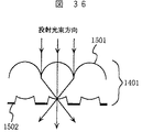
図36はレンチキュラレンズの一例を示す模式断面図であり、図37は該レンチキュラレンズの模式斜視図である。 FIG. 36 is a schematic cross-sectional view showing an example of a lenticular lens, and FIG. 37 is a schematic perspective view of the lenticular lens.
レンチキュラレンズ1401は、シリンドリカルレンズ状のレンズ1501を一方向に複数配列し、光の集光部以外の部分にブラックストライプ1502を設けた構成となっており、レンズ1501の焦点位置をスクリーンの観察面とすることで、理想的には投射光の損失がなく、外光に対するコントラスト比の低下を抑制することができる構成となっている。
The
一般に、レンチキュラレンズは、その母線を表示面に対して垂直方向になるように配列することで、水平方向に広い視野角が得られるようにしている。従って、垂直方向への配光はレンチキュラレンズの母材中もしくは、表面部に配合した拡散材による拡散のみのため、垂直方向の視野角は水平方向に比べてかなり狭くなる。また、レンチキュラレンズは直線的な形状のレンズを、規則的に配置しているため画像にモアレ干渉縞が発生し易い。 Generally, a lenticular lens is arranged such that its generatrix is arranged in a direction perpendicular to the display surface, so that a wide viewing angle can be obtained in the horizontal direction. Therefore, the light distribution in the vertical direction is only diffused in the base material of the lenticular lens or by the diffusing material blended in the surface portion, so that the viewing angle in the vertical direction is considerably narrower than in the horizontal direction. Further, since lenticular lenses are regularly arranged with linear lenses, moire interference fringes are likely to occur in the image.
これに対し、特許文献1には、図39に示す様な透明基材1601上に球状レンズ1602を敷き詰め、透明樹脂によって固定した構成の透過型スクリーンが開示されている。この構成では、金型を使用しないので製造上大きさの制限がなく、継ぎ目のない大画面の透過型スクリーンが実現できる。さらに、球状レンズ側から入射する光は球状レンズのレンズ効果により収束し、等方的に発散するため、水平、垂直両方向共に広視野角が得られる。
On the other hand,
さらに、非特許文献1には、オプティカルビーズを透明基材上に光吸収接着剤層を介して固着し、透明基材とは反対側のオプティカルビーズ表面を透明バックコートした構造のスクリーンが発表されている。
Furthermore, Non-Patent
また、特許文献2では微小球体状透明ビーズを、着色ホットメルト接着剤層と透明ホットメルト接着剤層とにより、透明基材上に固定した構造の平面型レンズが開示されている。これらの構造によれば、上記特許文献2号公報と同様に、ビーズのレンズ効果により水平,垂直両方向共に広く、等方的な視野角が得られる。さらに、外部から入射する不要光は、光吸収接着剤層(または、着色ホットメルト接着剤層)で吸収されるため、明るい環境下でも高コントラスト比が得られる。また、ビーズの直径を小さくすることで比較的容易に高解像度を実現できる。
上記従来の平面型レンズ(以下、配光制御素子と呼ぶ)を以下のとおり作製した。透明基材として厚さ120μmの平坦なポリエチレンテレフタレート(PET)樹脂フィルムを用い、その表面にポリエステル系ホットメルト接着剤からなる透明接着剤層を5μm、その上に同じくポリエステル系ホットメルト接着剤にカーボンブラックを10重量部配合した着色接着剤層を4.5μmを形成し、一旦固化する。 The conventional planar lens (hereinafter referred to as a light distribution control element) was produced as follows. A flat polyethylene terephthalate (PET) resin film having a thickness of 120 μm is used as a transparent substrate, a transparent adhesive layer made of a polyester-based hot melt adhesive is 5 μm on the surface, and the polyester-based hot-melt adhesive is carbon on the same. A colored adhesive layer containing 10 parts by weight of black is formed to have a thickness of 4.5 μm and is solidified once.
その上に屈折率1.935(波長589.3nm)、直径50μmの球状のガラス製透明ビーズを密に分散配置し、恒温槽内で透明接着剤層および着色接着剤層を加熱して軟化させつゝ、加圧板により透明ビーズを透明基材側へ加圧して着色接着剤層および透明接着剤層に埋没し、固着した。固着後の接着層の厚さは透明接着剤層と着色接着剤層とを合わせ約21μmで、透明ビーズはその直径の約58%が接着剤層から露出していた。 Further, spherical glass beads having a refractive index of 1.935 (wavelength: 589.3 nm) and a diameter of 50 μm are densely dispersed, and the transparent adhesive layer and the colored adhesive layer are heated and softened in a thermostatic bath. Then, the transparent beads were pressed to the transparent substrate side with a pressure plate, embedded in the colored adhesive layer and the transparent adhesive layer, and fixed. The thickness of the adhesive layer after fixing was about 21 μm, including the transparent adhesive layer and the colored adhesive layer, and about 58% of the diameter of the transparent beads was exposed from the adhesive layer.
作製した配光制御素子を、2次元光学スイッチ素子(ライトバルブ)としてTN型液晶表示素子を用いる投射装置を備えた背面投射型表示装置の透過型スクリーンとして評価したところ、水平方向、垂直方向共に±50°以上の広い視野角(ここでは正面輝度に対して1/2の輝度になる角度)が得られ、さらに、外部(観察者側)から配光制御素子へ入射する不要光は、着色接着剤層で吸収されて、明るい環境下でも低輝度な黒表示が実現できた。 The produced light distribution control element was evaluated as a transmissive screen of a rear projection display device provided with a projection device using a TN liquid crystal display element as a two-dimensional optical switch element (light valve). A wide viewing angle of ± 50 ° or more (here, an angle that is 1/2 of the front luminance) is obtained, and unnecessary light incident on the light distribution control element from the outside (observer side) is colored. Absorbed by the adhesive layer, a low-brightness black display was achieved even in a bright environment.
ところが、配光制御素子に映し出された画像を斜め方向から観察したところ、略同心円状の縞模様が現れて、画質が著しく劣化していることが分かった。さらに、斜め方向から観察した際、画像に好ましくない色度変化が生じることも分かった。 However, when the image projected on the light distribution control element was observed from an oblique direction, it was found that a substantially concentric striped pattern appeared and the image quality was significantly deteriorated. Furthermore, it was also found that an undesirable chromaticity change occurs in an image when observed from an oblique direction.
本発明の目的は上記縞模様の発生による画質の劣化が無い配光制御素子、およびこの配光制御素子を用いた高輝度、高コントラスト比、広視野角の表示装置を提供することにある。上記以外の目的については以下の記述から自ずと明らかになるであろう。 An object of the present invention is to provide a light distribution control element in which image quality is not deteriorated due to the occurrence of the stripe pattern, and a display device having a high luminance, a high contrast ratio, and a wide viewing angle using the light distribution control element. Other purposes will become apparent from the following description.
本発明者らは、縞模様の発生と色度変化の原因を探るため、上記従来の配光制御素子についてより詳細な検討を行なった。その結果、縞模様は配光制御素子に偏光が入射した際に生じるもので、透明基材の光学的異方性により該基材内を異なる角度で進行する光に異なる位相差が生じること、および、透明基材から出射する光のp偏光成分とs偏光成分のエネルギー透過率の差が組み合わされて生じることを見出した。また、本配光制御素子の配光特性は、入射する光の偏光状態に依存して変化するため、これが色度変化の原因なっていることを見出した。上記に基づき到達した本発明の要旨は次のとおりである。 The present inventors have conducted a more detailed study on the conventional light distribution control element described above in order to search for the cause of the stripe pattern and the chromaticity change. As a result, the stripe pattern is generated when polarized light enters the light distribution control element, and the optical anisotropy of the transparent base material causes different phase differences in light traveling at different angles in the base material. And it discovered that the difference of the energy transmittance of the p polarization | polarized-light component of the light radiate | emitted from a transparent base material, and an s-polarized light component combined occurred. Further, the present inventors have found that the light distribution characteristic of the present light distribution control element changes depending on the polarization state of incident light, which causes a change in chromaticity. The gist of the present invention achieved based on the above is as follows.
〔1〕 透明基材と、この透明基材の一方の面上に密に配置された多数の微小レンズと、前記微小レンズの略焦点位置に微小開口部を有する光吸収層を備えた配光制御素子において、前記透明基材が光学的に略等方な透明体、もしくは、一軸性光学異方性の透明体で構成されていることを特徴とする配光制御素子。
[1] A light distribution provided with a transparent substrate, a large number of microlenses arranged densely on one surface of the transparent substrate, and a light absorption layer having a microopening at a substantially focal position of the microlens The light distribution control element according to
これを用いることにより、画質に影響を与えるような位相差の発生を抑制することで偏光入射時の縞模様の発生を解消したものである。 By using this, the generation of a stripe pattern at the time of polarization incidence is eliminated by suppressing the generation of a phase difference that affects the image quality.
〔2〕 光学画像を投射する投射装置と、前記投射装置からの投射光が背面から入射し、これを前面に表示する透過型スクリーンを備える背面投射型表示装置において、
前記投射装置が光源と、該光源からの光を画像情報に応じて光学画像に変調する2次元光学スイッチ素子と、変調後の光学画像を拡大投射する投射レンズを有する単管式投射装置を備え、
前記投射装置から出射された前記変調後の光学画像が前記透過型スクリーンへ入射する際、前記2次元光学スイッチ素子で形成された光学画像光の偏光状態を可視波長全域で略一致させる偏光状態揃え手段を有し、
前記透過型スクリーンが、透明基材と、この透明基材の一方の面上に密に配置された多数の微小レンズと、前記微小レンズの略焦点位置に微小開口部を有する光吸収層を備え、前記透明基材が光学的に略等方な透明体、もしくは、一軸性光学異方性の透明体で構成された配光制御素子と、この配光制御素子の投射光入射側に設けた光束平行化手段により構成されていることを特徴とする背面投射型表示装置。
[2] In a rear projection type display device including a projection device that projects an optical image, and a transmissive screen on which projection light from the projection device is incident from the back and displays the light on the front surface,
The projection apparatus includes a single-tube projection apparatus having a light source, a two-dimensional optical switch element that modulates light from the light source into an optical image according to image information, and a projection lens that magnifies and projects the modulated optical image. ,
Polarization state alignment that substantially matches the polarization state of the optical image light formed by the two-dimensional optical switch element in the entire visible wavelength range when the modulated optical image emitted from the projection device is incident on the transmissive screen. Having means,
The transmissive screen includes a transparent substrate, a large number of microlenses arranged densely on one surface of the transparent substrate, and a light absorption layer having a microopening at a substantially focal position of the microlens. The transparent substrate is provided on the projection light incident side of the light distribution control element composed of an optically isotropic transparent body or a transparent body of uniaxial optical anisotropy. A rear projection display device comprising a light beam collimating means.
上記により、配光制御素子へ入射する投射光(光学画像光)の偏光状態は可視波長域全域で一致している。このため、配光制御素子の配光特性の偏光依存性による色付きは起こらず、斜め方向から観察しても色度変化のない高画質な表示を実現することができる。 As described above, the polarization state of the projection light (optical image light) incident on the light distribution control element is the same in the entire visible wavelength range. For this reason, coloring due to the polarization dependence of the light distribution characteristic of the light distribution control element does not occur, and high-quality display without chromaticity change can be realized even when observed from an oblique direction.
さらに、上記配光制御素子へ入射する画像光は、略平行状態で、かつ、実質的に入射角度0°で入射するため、配光制御素子での透過率低下が抑制されて明るい表示画像が得られる。 Furthermore, since the image light incident on the light distribution control element is incident in a substantially parallel state and substantially at an incident angle of 0 °, a decrease in transmittance at the light distribution control element is suppressed, and a bright display image is displayed. can get.
〔3〕 前記2次元光学スイッチ素子が偏光を利用して表示を行なう2次元光学スイッチ素子であり、前記2次元光学スイッチ素子で形成された光学画像光の偏光状態を電気ベクトルの振動方向が前記透過型スクリーン表示面に対して水平方向の直線偏光、垂直方向の直線偏光、円偏光、楕円偏光のいずれかに変換する偏光状態変換手段を備えている前記の背面投射型表示装置。 [3] The two-dimensional optical switch element is a two-dimensional optical switch element that performs display using polarized light, and the polarization direction of the optical image light formed by the two-dimensional optical switch element indicates the vibration direction of the electric vector as described above. The rear projection display device comprising a polarization state conversion means for converting the light into one of horizontal linearly polarized light, vertical linearly polarized light, circularly polarized light, and elliptically polarized light with respect to the transmissive screen display surface.
上記により、配光制御素子に入射する光学画像光の偏光状態を制御できるため、透過型スクリーンの構成を変えなくても、配光制御素子の配光特性の偏光依存性により、視野角特性を容易に変えられる背面投射型表示装置が実現できる。 As described above, since the polarization state of the optical image light incident on the light distribution control element can be controlled, the viewing angle characteristic can be adjusted by the polarization dependency of the light distribution characteristic of the light distribution control element without changing the configuration of the transmission screen. A rear projection display device that can be easily changed can be realized.
〔4〕 前記背面投射型表示装置において、観察者の有無を感知する観察者感知部と、該観察者感知部の感知信号により水平および垂直方向の観察者の位置を断する観察者位置判断手段と、該観察者位置判断手段の情報に基づき偏光状態変換素子に制御信号を出力する制御信号出力手段を備えている前記の背面投射型表示装置。 [4] In the rear projection display device, an observer sensing unit that senses the presence or absence of an observer, and an observer position determination unit that cuts off the position of the observer in the horizontal and vertical directions based on a sensing signal of the observer sensing unit And the rear projection display device comprising control signal output means for outputting a control signal to the polarization state conversion element based on information from the observer position determination means.
上記により、観察者の位置を自動的に判断し、この位置情報をもとに投射光の偏光状態を変えることで観察者の位置に応じた視野角特性を得ることが可能となる。つまり、観察者の位置に応じて視野角特性を自動的に変え、限られた映像光を観察者の方向へ有効に配光して、観察者に良好な映像を提供するものである。 As described above, it is possible to automatically determine the position of the observer, and change the polarization state of the projection light based on this position information, thereby obtaining viewing angle characteristics corresponding to the position of the observer. In other words, the viewing angle characteristic is automatically changed according to the position of the observer, and the limited image light is effectively distributed in the direction of the observer to provide a good image to the observer.
〔5〕 前記投射装置が光源と、該光源からの光を画像情報に応じて光学画像に変調する2次元光学スイッチ素子と、変調後の光学画像を拡大投射する投射レンズを有する単管式投射装置を備え、
前記透過型スクリーンが、透明基材と、該透明基材の一方の面上に密に配置された多数の微小レンズと、前記微小レンズの略焦点位置に微小開口部を有する光吸収層を有する配光制御素子と、該配光制御素子の投射光入射側に配置された光束平行化手段を有しており、
前記投射装置から出射し、前記透過型スクリーンに入射する投射光を略無偏光とする無偏光化手段を有することを特徴とする背面投射型表示装置。
[5] Single tube projection in which the projection device includes a light source, a two-dimensional optical switch element that modulates light from the light source into an optical image according to image information, and a projection lens that magnifies and projects the modulated optical image. Equipped with equipment,
The transmissive screen has a transparent substrate, a large number of microlenses arranged densely on one surface of the transparent substrate, and a light absorption layer having a microopening at a substantially focal position of the microlens. A light distribution control element, and a light beam collimating unit disposed on the incident light incident side of the light distribution control element,
A rear projection type display device comprising: a non-polarization means for making the projection light emitted from the projection device and incident on the transmission screen substantially non-polarized.
上記により、透過型スクリーンを構成する配光制御素子に入射する光学画像光は無偏光となっているため、配光制御素子の配光特性の偏光依存性による色度変化は起こらない。また、配光制御素子の透明基材の光学異方性によって、偏光入射時に生じる縞模様も発生しないため、画質劣化のない美しい画像を得ることができる。また、透明基材として光学異方性のある透明体を用いても画質の劣化がないので、その材料の選択範囲が広くなり、より安価で、高強度の配光制御素子からなる透過型スクリーンが実現できる。 As described above, since the optical image light incident on the light distribution control element constituting the transmissive screen is non-polarized light, the chromaticity change due to the polarization dependence of the light distribution characteristic of the light distribution control element does not occur. Further, since a stripe pattern generated at the time of polarized light incidence does not occur due to the optical anisotropy of the transparent base material of the light distribution control element, a beautiful image without image quality deterioration can be obtained. In addition, even if a transparent body having optical anisotropy is used as a transparent base material, there is no deterioration in image quality, so the selection range of the material is widened, and the transmission screen is made of a light distribution control element that is less expensive and has high strength. Can be realized.
〔6〕 透明電極と配向膜が積層形成され、かつ、前記配向膜形成面を対向させて一定の間隙をもって接合された一対の透明基板と、前記間隙に封入された液晶層と、前記透明電極に画像信号に対応した電圧を印加する電圧印加手段と、前記一対の透明基板の光入射面側と光出射面側に偏光子および検光子を配置した液晶表示装置において、
前記一対の透明基板の背面に略平行な光を出射するバックライト装置を配置し、
前記一対の透明基板の光出射面側に、透明基材と、この透明基材の一方の面上に密に配置された多数の微小レンズと、前記微小レンズの略焦点位置に微小開口部を有する光吸収層を備え、前記透明基材が光学的に略等方な透明体、もしく、一軸性光学異方性の透明体で構成された配光制御素子を配置したことを特徴とする液晶表示装置。
[6] A pair of transparent substrates in which a transparent electrode and an alignment film are laminated, and the alignment film forming surfaces are opposed to each other and bonded with a certain gap, a liquid crystal layer sealed in the gap, and the transparent electrode In a liquid crystal display device in which a voltage applying means for applying a voltage corresponding to an image signal to the light input surface side and the light output surface side of the pair of transparent substrates is arranged with a polarizer and an analyzer,
A backlight device that emits light substantially parallel to the back of the pair of transparent substrates is disposed,
On the light exit surface side of the pair of transparent substrates, a transparent base material, a large number of microlenses arranged densely on one surface of the transparent base material, and a microscopic opening at a substantially focal position of the microlens A light distribution control element comprising a light absorbing layer having a transparent body that is optically substantially isotropic, or a transparent body having uniaxial optical anisotropy. Liquid crystal display device.
これにより、良好な画質が得られる正面近傍の限定された範囲の光のみを配光制御素子により等方的に拡散することができるので、広い視野角範囲で色調変化や階調反転がなく、コントラスト比の高い画像が得られる液晶表示装置が実現できる。 As a result, only a limited range of light near the front where good image quality can be obtained can be diffused isotropically by the light distribution control element, so there is no color change or gradation inversion over a wide viewing angle range, A liquid crystal display device capable of obtaining an image with a high contrast ratio can be realized.
〔7〕 前記一対の透明基板の光入射面に偏光子を配置し、光出射面に透明基板側から順に検光子、配光制御素子を配置し、さらに、前記検光子の直線偏光の透過軸を表示面に対して水平方向に配置した前記液晶表示装置。 [7] A polarizer is disposed on the light incident surfaces of the pair of transparent substrates, an analyzer and a light distribution control element are disposed in order from the transparent substrate side on the light exit surface, and a transmission axis of linearly polarized light of the analyzer is further provided. The liquid crystal display device in which is disposed in a horizontal direction with respect to the display surface.
これにより、配光制御素子の配光特性の偏光依存性により、表示面に対して垂直方向よりも水平方向の視野角が広くなり、限られた光を観察者に有効に配分することができる。 Thereby, the viewing angle in the horizontal direction is wider than the vertical direction with respect to the display surface due to the polarization dependence of the light distribution characteristic of the light distribution control element, and the limited light can be effectively distributed to the observer. .
〔8〕 前記一対の透明基板の光入射面に偏光子を配置し、光出射面に透明基板側から順に検光子、配光制御素子を配置し、さらに、前記検光子と前記配光制御素子の間に位相差板を配置した前記液晶表示装置。 [8] A polarizer is disposed on the light incident surface of the pair of transparent substrates, an analyzer and a light distribution control element are disposed in this order from the transparent substrate side on the light exit surface, and the analyzer and the light distribution control element are further disposed. The liquid crystal display device in which a retardation plate is disposed between them.
これにより、配光制御素子に入射する光の偏光状態を、検光子と配光制御素子の間に配置した位相板によって任意に変え得るので、位相差板を変更するだけで配光制御素子の配光特性の偏光依存性を利用して、所望の視野角のものを得ることができる。 As a result, the polarization state of the light incident on the light distribution control element can be arbitrarily changed by the phase plate disposed between the analyzer and the light distribution control element. A desired viewing angle can be obtained by utilizing the polarization dependency of the light distribution characteristic.
上記のとおり、本発明の配光制御素子は、透明基材として光学的に略等方、あるいは、面内に光学軸を有する一軸異方性の透明体を用いることで、偏光を入射しても、縞模様の発生による画質劣化がなく、広い視野角が得られるという効果がある。従って、本発明の配光制御素子は液晶表示装置のように偏光を利用する表示装置の視野角拡大手段として用いることができる。 As described above, the light distribution control element of the present invention is substantially optically isotropic as a transparent substrate, or uses a uniaxially anisotropic transparent body having an optical axis in the plane so that polarized light is incident. However, the image quality is not deteriorated due to the generation of the stripe pattern, and a wide viewing angle can be obtained. Therefore, the light distribution control element of the present invention can be used as a viewing angle widening means of a display device using polarized light such as a liquid crystal display device.
また、本発明の背面投射型表示装置は、その透過型スクリーンを本発明の配光制御素子と、その光入射側に配置したフレネルレンズとで構成し、配光制御素子に入射する投射光の入射角度を実質的に0度としたことで、配光制御素子での透過率低下が抑制され、明るい表示画像が得られる。さらに、投射装置として単管式の投射装置を用いることで、配光制御素子の光入射角度依存性により生じるカラーシフトや色付きが生じないので、高品位な画像が得られる。 Further, the rear projection type display device of the present invention comprises the transmissive screen composed of the light distribution control element of the present invention and a Fresnel lens disposed on the light incident side of the projection light incident on the light distribution control element. By making the incident angle substantially 0 degrees, a decrease in transmittance at the light distribution control element is suppressed, and a bright display image is obtained. Furthermore, by using a single-tube projection device as the projection device, color shift and coloring caused by the light incident angle dependency of the light distribution control element do not occur, so that a high-quality image can be obtained.
また、本発明の背面投射型表示装置では、投射装置から出射する投射光の偏光状態を、各色光共に一致させることで配光制御素子の配光特性の偏光依存性により生じる色付きを解消して、高品位な画像を得ることができる。 Further, in the rear projection type display device of the present invention, the coloration caused by the polarization dependency of the light distribution characteristic of the light distribution control element is eliminated by matching the polarization state of the projection light emitted from the projection device with each color light. High-quality images can be obtained.
さらに、配光制御素子が、どの角度から見ても明るく広い視野角特性を有し、外部不要光による迷光の低減効果が高いので、明るい環境下でも低輝度な黒表示の実現により、高コントラスト比の表示が実現できる。 In addition, the light distribution control element has a bright and wide viewing angle characteristic when viewed from any angle, and is highly effective in reducing stray light caused by external unnecessary light. A ratio display can be realized.
また、本発明の背面投射型表示装置では、配光制御素子の微小レンズとして、略同心円状の微小レンズを用い、透過型スクリーンに投射される光の偏光状態を変え得る偏光状態変換素子を設けたことで、スクリーンの構成を変えることなく、表示装置の視野角特性を容易に変え得ると云う効果がある。 In the rear projection display device of the present invention, a substantially concentric minute lens is used as the minute lens of the light distribution control element, and a polarization state conversion element that can change the polarization state of the light projected on the transmission screen is provided. Thus, there is an effect that the viewing angle characteristics of the display device can be easily changed without changing the configuration of the screen.
さらに、この背面投射型表示装置に観察者の有無を感知する観察者感知部と、該感知部の感知信号により観察者の水平および垂直方向の位置を判断する観察者位置判断手段と、該位置判断手段の情報に基づき偏光状態変換素子に制御信号を出力する制御信号出力手段を付加したことで観察者の位置を自動的に判断して投射光の偏光状態を変えることで、観察者の位置に応じた視野角特性を得ることが可能となる。つまり、観察者の位置に応じて視野角特性が自動的に変わり、限られた映像光が観察者の方向へ有効に配光できるので、観察者は任意の位置で良好な映像が得られると云う効果がある。 Further, an observer sensing unit that senses the presence or absence of an observer on the rear projection display device, an observer position judging means that judges the horizontal and vertical positions of the observer based on a sensing signal of the sensing unit, and the position By adding a control signal output means for outputting a control signal to the polarization state conversion element based on the information of the judgment means, the position of the observer is changed by automatically judging the position of the observer and changing the polarization state of the projected light. It is possible to obtain a viewing angle characteristic corresponding to. In other words, the viewing angle characteristics automatically change according to the position of the observer, and the limited image light can be effectively distributed in the direction of the observer, so that the observer can obtain a good image at an arbitrary position. There is an effect.
また、本発明の背面投射型表示装置では、透過型スクリーンへ入射する投射装置からの投射光を無偏光とすることで、配光制御素子の配光特性の偏光依存性による色付きや、縞模様のない高品位な画像を得ることができる。 Further, in the rear projection type display device of the present invention, the projection light from the projection device incident on the transmissive screen is made non-polarized, so that the color distribution due to the polarization dependency of the light distribution characteristic of the light distribution control element or the stripe pattern High-quality images with no image can be obtained.
この場合、配光制御素子の透明基材としては、光学異方性のある材料を用いてもよいため、該材料の選択範囲が広くなり、より安価で強度の高い材料を用いた透過型スクリーンを低コストで実現できる。 In this case, since a material having optical anisotropy may be used as the transparent base material of the light distribution control element, the selection range of the material is widened, and a transmission screen using a cheaper and higher strength material. Can be realized at low cost.
また、本発明の液晶表示装置では、その表面側に本発明に係る配光制御素子を配置し、バックライト装置に略平行な照明光を出射するものを用いることより、正面近傍の範囲の光のみを配光制御素子により等方的に拡散することができるため、広い視野角範囲で色調変化や階調反転がなく、コントラスト比の高い画像の液晶表示装置が得られる。 Further, in the liquid crystal display device of the present invention, the light distribution control element according to the present invention is arranged on the surface side thereof, and light that emits illumination light substantially parallel to the backlight device is used. Only the light distribution control element can diffuse isotropically, so that there is no color tone change or gradation reversal in a wide viewing angle range, and a liquid crystal display device with a high contrast ratio can be obtained.
さらに、本発明の液晶表示装置では配光制御素子に入射する光を表示面に対して水平方向の振動方向を有する直線偏光とすることで、表示面垂直方向よりも水平方向の視野角を広くして、限られた光を観察者に有効に配分できる。 Further, in the liquid crystal display device of the present invention, the light incident on the light distribution control element is linearly polarized light having a vibration direction in the horizontal direction with respect to the display surface, so that the viewing angle in the horizontal direction is wider than the vertical direction on the display surface. Thus, the limited light can be effectively distributed to the observer.
また、本発明の液晶表示装置では配光制御素子に入射する光の偏光状態を、検光子と配光制御素子の間に配置する位相差板によって任意に変えられるため、位相差板を変更するだけで、配光制御素子の配光特性の偏光依存性を利用し、所定の視野角を得ることもできる。 Further, in the liquid crystal display device of the present invention, the polarization state of the light incident on the light distribution control element can be arbitrarily changed by the phase difference plate arranged between the analyzer and the light distribution control element, so the phase difference plate is changed. Only by using the polarization dependence of the light distribution characteristic of the light distribution control element, a predetermined viewing angle can be obtained.
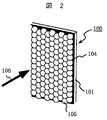
本発明の実施の形態について図面に基づき説明する。図1は本発明の配光制御素子の一例を示す模式断面図で、図2はその模式斜視図である。 Embodiments of the present invention will be described with reference to the drawings. FIG. 1 is a schematic cross-sectional view showing an example of a light distribution control element of the present invention, and FIG. 2 is a schematic perspective view thereof.
この配光制御素子は、透明基材101と、その表面に形成されたホットメルト接着剤層104と、該接着剤層104に固着された複数の微小球状の透明ビーズ105で構成される。
This light distribution control element is composed of a
透明基材101は、それ自体が剛性を有する板状の基材であってもよいし、フィルム状の基材であってもよいが、光学的に略等方、もしくは、板面または膜面に平行な方向に光学軸を有する1軸異方性の透明体を用いることが重要である。
The
具体的にはガラス板、射出成形によるアクリル樹脂板等の光学的に略等方な透明板、あるいは、キャスティング法やエキストルージョン法等により製膜し、必要に応じて一軸延伸したポリカーボネート樹脂、塩化ビニル樹脂、ポリエステル系樹脂、セルロース系樹脂、ポリビニルアルコール樹脂、ポリオレフィン系樹脂等の光学的に略等方、または、膜面に平行な光学軸を有する1軸異方性の透明フィルムが用いられる。 Specifically, a glass plate, an optically isotropic transparent plate such as an acrylic resin plate formed by injection molding, or a polycarbonate resin formed by a casting method or an extrusion method, and uniaxially stretched as necessary. A uniaxial anisotropic transparent film having an optical axis substantially parallel to the film surface, such as a vinyl resin, a polyester resin, a cellulose resin, a polyvinyl alcohol resin, and a polyolefin resin, is used.
ホットメルト接着剤層104は、透明層102と着色層103の順に積層した構成となっている。該接着剤層は透明基材101と透明ビーズ105に対して十分な接着力を有するものを用いる。これにはアクリル系樹脂、ポリエステル系樹脂、ポリアミド系樹脂、ポリウレタン系樹脂等からなるホットメルト接着剤を用いることができる。また、着色層103は、これらの接着剤をベースにしてカーボンブラック等の顔料を分散させることで着色したもの、あるいは、染料による染色により着色したものなどが用いられる。
The hot melt
透明ビーズ105は、ガラス製もしくは光学的に等方で透明な樹脂製の球状ビーズが用いられ、その屈折率が高いものほど透明ビーズに入射した光の屈折角が大きくなるため、配光制御素子の光出射角度(視野角)は広くなる。しかし、その分正面の輝度が低下すると共に表面での反射や、透明基材101と空気との界面での反射が多くなり全光線透過率は低下する。
As the
また、透明ビーズ105の光出射面側の開口部、即ち、透明ビーズ105と透明接着剤層102との接触部分に効率良く光を通すためには、透明ビーズに入射した光の光出射面側での収束面積を小さくする方が有利である。この場合、透明ビーズの光入射側の媒質が空気であれば、屈折率1.6〜2.1程度とすることで、光出射面での収束面積は十分小さくできる。さらに、上記屈折率を1.9〜2.1とすることで、より小さな収差で集光することが可能である。
Further, in order to transmit light efficiently through the opening on the light exit surface side of the
透明ビーズ105の屈折率は、これらの条件を踏まえた上で配光制御素子に要求される特性、即ち、視野角や明るさ(ゲイン)の仕様に適合するよう選択する。また、必要に応じて異なる屈折率の透明ビーズを混合して用いることもできる。
The refractive index of the
配光制御素子100を表示装置のスクリーンあるいは視野角拡大手段として用いる場合は、透明ビーズ105の直径は表示される画像の解像度に直接影響する。即ち、配光制御素子に表示される画像は、透明ビーズ105の直径以下には解像できない。よって、透明ビーズの直径は配光制御素子に表示すべき画像の画素よりも小さくする必要がある。
When the light
高い解像度を得るには透明ビーズ105の直径は小さいほどよいが、透明ビーズ105の直径が光の波長領域に近づくと、透過光の散乱要因が大きくなり正面での輝度や透過率が低下するため、自とその下限は規定される。
To obtain high resolution, the smaller the diameter of the
上記透明ビーズ105の直径は、表示画像の画素ピッチの1/2以下で、実用的には20〜100μm程度が望ましい。また、透明ビーズ105は、透明基材101の面上に均一、かつ、最大密度に配置するため、できるだけ粒径のばらつきが小さいことが望ましい。実際には粒径のばらつきを10%以内に収めれば配光制御素子としての機能は満足される。
The diameter of the
また、透明ビーズ105は、内部に気泡があると透過率の低下要因となるため、気泡のないものが望ましい。
Moreover, since the
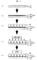
次に、本発明の配光制御素子100の製法の一例を図3を用いて説明する。
Next, an example of a method for producing the light
工程(a):透明基材101上に加熱溶融状態、あるいは、溶剤により溶解、または、溶液にコロイド状に分散したホットメルト透明接着剤を、例えば、スピンコート、ナイフコート、ロールコート、スプレーコート、ブレードコートにより塗布し、透明接着剤層102を形成する。
Step (a): A hot-melt transparent adhesive dissolved in a heat-melted state on a
工程(b):その上に着色接着剤層103を透明接着剤層102と同様の方法で積層し、ホットメルト接着剤層104を形成する。この際、着色接着剤層103と透明接着剤層102が混合しないようにするため、着色接着剤層103の形成は、透明接着剤層102が高温の溶融状態の場合は強制冷却もしくは自然冷却によって温度を下げる。また、透明接着剤層102が溶剤中に溶融状態、または、溶液中にコロイド状に分散した状態であれば乾燥器で溶媒を蒸発させて固化あるいは半固化するとよい。
Step (b): A colored
工程(c):複数の透明ビーズ105を着色接着剤層103上に少なくとも一層、最大充填密度となるよう分散配置する。この際、着色接着剤層103は固化または半固化状態では接着性がないので、透明ビーズ105は比較的容易に最大充填密度に分散配置できる。
Step (c): At least one
次いで上記を恒温槽、赤外線ヒータ等の加熱手段により加熱し、ホットメルト接着剤層104を軟化,溶融し、透明ビーズ105を透明基材101に向かって自重あるいは加圧手段により、ホットメルト接着剤層104内に所定の量だけ埋没させる。
Next, the above is heated by heating means such as a thermostatic bath, an infrared heater, etc., the hot melt
工程(d):透明ビーズ105が埋没した状態で、ホットメルト接着剤層104の温度を常温まで下げて固化し、透明ビーズを固着する。
Step (d): With the
なお、ホットメルト接着剤層104への透明ビーズ105の埋没深さは、該ビーズ直径の50〜80%が露出するようにすることが望ましい。露出量がこれより少ない場合は、着色接着剤層による吸収で透明ビーズ105への入射光量が低下して透過率が低下する。また、露出量がこれより大きい場合にはビーズの固着性が不十分となる。
Note that it is desirable that the buried depth of the
上記により、本発明の配光制御素子は、透明ビーズ105が1層分だけ、ほぼ最大充填密度で分散配置され、かつ、その直径の半分以上をホットメルト接着剤層104から光入射側に露出固定させたものを得ることができる。
As described above, in the light distribution control element of the present invention, only one
次に、本発明の配光制御素子の光学的な作用について図1により説明する。配光制御素子100は、前記のとおり光入射面側に透明ビーズ105が1層分だけ、ほぼ最大充填密度で分散配置され、かつ、ビーズ直径の半分以上がホットメルト接着剤層104から光入射側に露出,固定されている。
Next, the optical action of the light distribution control element of the present invention will be described with reference to FIG. In the light
従って、配光制御素子100に対して垂直入射した平行な入射光106は、その一部が透明ビーズ105同士の隙間の着色接着剤層103に吸収されるが、大部分は透明ビーズ105に入射する。該入射光は透明ビーズ105の屈折作用により収束しつつ、透明ビーズ105と透明接着剤層102との接触部に形成された開口部を通過し、透明基材101を透過,発散しながら出射する。つまり、透明ビーズへの入射光は、透明ビーズのレンズ効果で収束され、等方的に発散するため、等方で広い視野角の配光制御素子が得られる。
Therefore, a part of the parallel incident light 106 perpendicularly incident on the light
また、外部から入射する不要光107は、着色接着剤層102で吸収されて、不要光が迷光となり観察されることがない。従って、明るい環境下でも外部不要光による迷光の低減効果が高く、観察者がどの角度から見ても明るく、等方的な視野角特性の配光制御素子を得ることができる。
Further, the
〔偏光入射時の縞模様の解消〕
次に本発明の配光制御素子特有の効果を明らかにするため、従来の課題であった偏光入射時に斜め方向からの観察した際に現れる縞模様の発生について説明する。
[Removal of striped pattern when polarized light is incident]
Next, in order to clarify the effect peculiar to the light distribution control element of the present invention, the generation of a striped pattern that appears when observed from an oblique direction at the time of polarized light incidence, which was a conventional problem, will be described.
図4は、従来(本発明に係る課題について配慮がなされていない)の配光制御素子の偏光入射時の光出射特性を等輝度線図で表したものである。 FIG. 4 shows a light emission characteristic at the time of polarized light incidence of a conventional light distribution control element (consideration is not given to the problem according to the present invention) by an isoluminance diagram.
この等輝度線図は、図5に示す出射角度と方位角度で構成する座標系内に最大輝度を100%とし、10%間隔で等輝度となる点を結び表示したものである。
図4中、中央部が出射角度0°(正面)を示し、点線の同心円が出射角度(10°間隔)を示す。また、方位角度は図面下方向を0°とし、反時計回りに増加するように表示する。
This isoluminance diagram is obtained by connecting and displaying the points where the maximum luminance is 100% in the coordinate system constituted by the emission angle and the azimuth angle shown in FIG.
In FIG. 4, the center portion indicates the
図4に示すとおり、従来の配光制御素子では偏光を入射すると出射角度40°近傍の2点を中心とした略同心円状の輝度変動が現れる。これは、実際には斜め方向から観察した際に縞模様として視認することができる。 As shown in FIG. 4, in the conventional light distribution control element, when polarized light is incident, luminance variations in a substantially concentric shape centering on two points near an emission angle of 40 ° appear. This can be visually recognized as a striped pattern when observed from an oblique direction.
本測定に用いた従来の配光制御素子は、透明基材101として厚さ120μmの平坦なポリエチレンテレフタレート(PET)フィルムを用いた。その表面にポリエステル系ホットメルト接着剤からなる透明接着剤層5μm、その上にポリエステル系ホットメルト接着剤にカーボンブラックを10重量部配合した着色接着剤層4.5μmを形成し、この上に屈折率1.935(波長589.3nm)、直径50μmの球状ガラス透明ビーズを密に分散配置し、上記着剤層に埋没、固着したものである。
In the conventional light distribution control element used for this measurement, a flat polyethylene terephthalate (PET) film having a thickness of 120 μm was used as the
透明ビーズ固着後の接着層の厚さは、透明層と着色層合わせて約21μmで、透明ビーズはその直径の約58%が接着剤層から露出していた。 The thickness of the adhesive layer after fixing the transparent beads was about 21 μm, including the transparent layer and the colored layer, and about 58% of the diameter of the transparent beads was exposed from the adhesive layer.
ここで、上記配光制御素子では透明基材101として、2軸延伸したPETフィルムを用いた。これは、2軸延伸フィルムは無延伸フィルムに比べて引張強さや衝撃強さが増大し、透明性、使用温度範囲も改良されるなど物性が著しく向上するためである。また、PETフィルムは、ガラス製透明ビーズとの接着性が良いポリエステル系ホットメルト接着剤との密着性がよく、さらに上記ホットメルト接着剤(溶剤:トルエン)に対する耐溶剤性が良好であるためである。
Here, in the light distribution control element, a biaxially stretched PET film was used as the
上記理由から透明基材に2軸延伸PETフィルムを用いたが、一般に、2軸延伸フィルムは3つの主屈折率(フィルム膜面に垂直な方向:Z軸方向、膜面に平行で互いに直交する方向:X軸およびY軸方向)が互いに異なる2軸異方性の物質となる。 For the above reasons, a biaxially stretched PET film was used as the transparent substrate. In general, however, the biaxially stretched film has three main refractive indices (direction perpendicular to the film film surface: Z-axis direction, parallel to the film surface and orthogonal to each other. Biaxially anisotropic materials with different directions (X-axis and Y-axis directions).
2軸異方性とは図6に示すように屈折率楕円体を考えたとき、その切断面形状が円形となり、屈折率異方性が生じない方向が2方向定まる物質のことである。この光の方向を光学軸と云い、光学軸には屈折率異方性がないため、これと平行に進む偏光には位相差が生じない。例えば、上記従来例に用いたPETフィルムの場合、3つの主屈折率はnx=1.678、ny=1.645、nz=1.497であり、図7に示すとおり光学軸はZ軸と23.3°の角度を成すZX平面内に2本存在する。 Biaxial anisotropy is a substance in which when the refractive index ellipsoid is considered as shown in FIG. 6, the shape of the cut surface is circular and the direction in which refractive index anisotropy does not occur is determined in two directions. The direction of this light is called the optical axis, and since there is no refractive index anisotropy in the optical axis, there is no phase difference in polarized light traveling in parallel therewith. For example, in the case of the PET film used in the above-mentioned conventional example, the three main refractive indexes are nx = 1.678, ny = 1.645, nz = 1.497, and the optical axis is Z-axis as shown in FIG. There are two in the ZX plane at an angle of 23.3 °.
PETフィルム内を光学軸に沿って進んだ光は空気との界面で屈折し、出射角度41.6°で出射するため、図4に示した出射角度40°近傍の輝度変動の略中心位置はこの光学軸に相当している。 The light that has traveled along the optical axis in the PET film is refracted at the interface with the air and is emitted at an exit angle of 41.6 °. Therefore, the approximate center position of the luminance fluctuation in the vicinity of the exit angle of 40 ° shown in FIG. It corresponds to this optical axis.
ここで、特定の偏光状態(直線偏光あるいは楕円偏光)の光が配光制御素子に入射する場合を考える。この場合、配光制御素子に入射した光の大部分は透明ビーズによって収束され、その後、発散して様々な角度でPETフィルム内を進む。この際、PETフィルム内を光学軸に沿って進む光には位相差が生じないので偏光状態は変化しない。 Here, consider a case where light of a specific polarization state (linearly polarized light or elliptically polarized light) is incident on the light distribution control element. In this case, most of the light incident on the light distribution control element is converged by the transparent beads, and then diverges and travels through the PET film at various angles. At this time, since the phase difference does not occur in the light traveling along the optical axis in the PET film, the polarization state does not change.
ところが、光学軸とずれた角度で進む光には、その角度のずれに対応した位相差が生じるため、偏光の状態、即ち、PETフィルム光出射側界面において光入射面に平行なp偏光成分と、垂直なs偏光成分の割合が変化する。つまり、光学軸方向と異なる方向に進む光には、光学軸とのずれ大きさに対応して、p偏光成分が多い光と、s偏光成分が多い光とが交互に現れることになる。 However, since the light traveling at an angle shifted from the optical axis has a phase difference corresponding to the shift in the angle, the polarization state, that is, the p-polarized component parallel to the light incident surface at the PET film light exit side interface, The ratio of the vertical s-polarized component changes. That is, in light traveling in a direction different from the optical axis direction, light having a large amount of p-polarized light component and light having a large amount of s-polarized light component appear alternately corresponding to the magnitude of deviation from the optical axis.
ここで、一般に誘電体表面の屈折で、p偏光とs偏光とではエネルギー透過率に差が生じる。図8は、p偏光とs偏光のエネルギー透過率の違いを例示したもので、PETフィルムから空気中へ光が進行する際の光入射角度とエネルギー透過率の関係を示すグラフである。 Here, in general, the refraction of the dielectric surface causes a difference in energy transmittance between p-polarized light and s-polarized light. FIG. 8 illustrates the difference in energy transmittance between p-polarized light and s-polarized light, and is a graph showing the relationship between the light incident angle and the energy transmittance when light travels from the PET film into the air.
図8のように、p偏光とs偏光とでは最大30%以上の透過率の差が生じる。このため、p偏光成分が多い光と、s偏光成分が多い光とでは、透過光量に差が生じ、輝度の明暗が形成され、これが縞模様として視認されることになる。 As shown in FIG. 8, a difference in transmittance of 30% or more is maximum between p-polarized light and s-polarized light. For this reason, there is a difference in the amount of transmitted light between light with a large amount of p-polarized light component and light with a large amount of s-polarized light component, and brightness brightness is formed, which is visually recognized as a striped pattern.
特に透明ビーズに代表される微小レンズを用いた配光制御素子では、微小レンズに入射した光が収束し、発散しながら透明基材内を様々な角度で進行するため、透明基材内での光の進行角度の違いに基づく位相差の違いにより、出射光の輝度むら(変化)が非常に発生し易い。 In particular, in a light distribution control element using a microlens represented by transparent beads, the light incident on the microlens converges and travels at various angles while diverging. Due to the difference in phase difference based on the difference in the traveling angle of light, the luminance unevenness (change) of the emitted light is very likely to occur.
本発明の配光制御素子では、透明基材101として光学的に略等方、もしくは、膜面に平行な光学軸を有する1軸異方性のものを用いることを特徴としている。従って、本配光制御素子に入射する偏光は、透明ビーズにより収束し、発散しながら透明基材内を様々な角度で進行するが、透明基材が光学的に等方なため、進行角度による位相差の違いは生じず、偏光状態、即ち、p偏光成分とs偏光成分の割合は出射角度によっても殆ど変化しないので縞模様は発生しない。
In the light distribution control element of the present invention, the
また、配光制御素子に入射する偏光が直線偏光の場合は、透明基材が面内に光学軸を有する一軸異方性の物質であれば、入射直線偏光の電気ベクトルの振動方向を透明基材の遅相軸と平行もしくは垂直とすることで、透明基材内を通過する偏光の進行角度による位相差の違いを小さくでき、縞模様の発生を抑制することができる。 In addition, when the polarized light incident on the light distribution control element is linearly polarized light, if the transparent substrate is a uniaxially anisotropic material having an optical axis in the plane, the vibration direction of the electric vector of the incident linearly polarized light is transparent. By making the material parallel or perpendicular to the slow axis of the material, the difference in phase difference due to the traveling angle of polarized light passing through the transparent substrate can be reduced, and the occurrence of a striped pattern can be suppressed.
さらに、透明基材が光学的に異方性を有していても、透明基材内を進む光の進行角度よる位相差の違いが小さくて、偏光状態の変化が小さければ輝度の変化は視認されず許容される。 Furthermore, even if the transparent substrate has optical anisotropy, if the difference in phase difference due to the traveling angle of light traveling through the transparent substrate is small and the change in polarization state is small, the change in luminance is visible. Not allowed.
例えば、透明基材内部を進む光の進行角度の違いによる位相差の違いの最大値が1/2波長以下であれば、透明基材内部を通過する光の角度による偏光状態の変化は、最大でもp偏光成分100%の光がs偏光成分100%の光に変換されるに留まるので、輝度の変化は視認され難い。 For example, if the maximum value of the difference in phase difference due to the difference in the traveling angle of light traveling inside the transparent substrate is ½ wavelength or less, the change in the polarization state due to the angle of the light passing through the transparent substrate is maximum. However, since the light with 100% p-polarized light component is only converted to light with 100% s-polarized light component, the change in luminance is hardly visible.
より理想的には透明基材内部を通過する光の角度による位相差の違いの最大値を、1/4波長以下に留めることが望ましい。この場合は最大でも、例えば、p偏光成分100%の光はp偏光成分50%、s偏光成分50%の光への変換に留まるので、輝度変化はより認め難くなる。 More ideally, it is desirable to keep the maximum value of the difference in phase difference depending on the angle of light passing through the transparent substrate within a quarter wavelength. In this case, at most, for example, light with 100% p-polarized light component is only converted into light with 50% p-polarized light component and 50% s-polarized light component.
従って、ここで云う光学的に略等方な透明基材とは、透明基材内を進む光の進行角度の違いによる位相差の違いが小さいために、偏光状態の変化も小さくなり、輝度の変化が認められない程度の等方性を示すものを云う。 Therefore, the optically isotropic transparent base material referred to here is a small difference in phase difference due to the difference in the traveling angle of light traveling in the transparent base material, and therefore the change in the polarization state is small, and the luminance is reduced. This means something that is isotropic to the extent that no change is observed.
上記のとおり、本発明の配光制御素子では、透明基材として光学的に略等方、あるいは、面内に光学軸を有する一軸異方性の透明体を用いたので、偏光を入射しても、縞模様の発生による画質劣化が起こらず、広視野角が得られる。 As described above, in the light distribution control element of the present invention, the transparent base material is optically substantially isotropic, or a uniaxial anisotropic transparent body having an optical axis in the plane is used. However, the image quality is not deteriorated due to the generation of the stripe pattern, and a wide viewing angle can be obtained.
また、外部から配光制御素子100に入射する不要光107は着色接着剤層102で吸収されるため、不要光が迷光となって観察されることがない。従って、明るい環境下でも外部不要光による迷光が低減される。
Further, since
なお、上記のとおり誘電体表面のエネルギー透過率は、p偏光とs偏光で異なるため、透明ビーズ105、あるいは、透明基材101の表面においてp偏光成分の透過率は高く、s偏光成分の光は透過率が低くなる。その結果として、入射光の偏光状態によって出射光の配光特性に異方性が生じる。
Since the energy transmittance of the dielectric surface is different between p-polarized light and s-polarized light as described above, the transmittance of the p-polarized component is high on the surface of the
例えば、本配光制御素子に直線偏光を入射する場合、直線偏光の電気ベクトルの振動方向に平行な方向の視野角は、これと直交する方向よりも広くなる。この特性を利用すれば、電気ベクトルの振動方向が水平方向である直線偏光を本配光制御素子に入射するようにすることで、垂直方向の視野角よりも水平方向の視野角を大きくできる。 For example, when linearly polarized light is incident on the light distribution control element, the viewing angle in the direction parallel to the vibration direction of the electric vector of the linearly polarized light is wider than the direction orthogonal thereto. If this characteristic is utilized, the viewing angle in the horizontal direction can be made larger than the viewing angle in the vertical direction by making the linearly polarized light whose oscillation direction of the electric vector is horizontal enter the light distribution control element.
また、上記とは逆に、入射する直線偏光の電気ベクトルの振動方向を垂直にすることで、垂直方向の視野角を水平方向の視野角よりも大きくすることができる。さらに、配光制御素子に入射する光を円偏光とすれば、等方的な視野角を得ることも可能である。 Contrary to the above, the vertical viewing angle can be made larger than the horizontal viewing angle by making the oscillation direction of the electric vector of the incident linearly polarized light vertical. Furthermore, if the light incident on the light distribution control element is circularly polarized light, an isotropic viewing angle can be obtained.
即ち、本発明の配光制御素子は、これに入射する光の偏光状態を制御することで、視野角を任意に制御することが可能となる。 That is, the light distribution control element of the present invention can arbitrarily control the viewing angle by controlling the polarization state of the light incident thereon.
なお、これまでの説明では、微小レンズとして微小球状の透明ビーズを用いた場合について説明した。しかし、微小集光レンズの形状は集光作用を有する微小体であれば半球体、回転楕円体、円柱、あるいは半円柱、楕円柱等、球体に限るものではない。つまり、本発明の配光制御素子は、集光作用を有する微小レンズと、これを支持する透明基材から構成され、光出射側に配置した透明基材を光学的に略等方な透明体で構成することで、透明基材内を異なる角度で進む光に、異なる位相差が発生するのを防止して、縞模様(輝度むら)の発生を解消したものである。 In the above description, the case where microspherical transparent beads are used as the microlens has been described. However, the shape of the micro condensing lens is not limited to a sphere, such as a hemisphere, a spheroid, a cylinder, a semi-cylinder, or an elliptic cylinder, as long as it has a condensing function. That is, the light distribution control element of the present invention is composed of a microlens having a condensing function and a transparent base material that supports the lens, and the transparent base material disposed on the light emitting side is optically substantially isotropic transparent body. This prevents the occurrence of different phase differences in the light traveling at different angles in the transparent base material, thereby eliminating the occurrence of striped patterns (brightness unevenness).
次に本発明の配光制御素子を具体的な実施例に基づき説明する。 Next, the light distribution control element of the present invention will be described based on specific examples.
〔配光制御素子の実施例1〕
本実施例では、図1,2に示す配光制御素子を以下のとおり作製した。まず、厚さ80μmの平坦なトリアセチルセルロース(TAC)フィルムからなる透明基材101の一表面に、溶剤にトルエンを用いたポリエステル系ホットメルト透明接着剤(東洋紡績製)を、乾燥後の厚さが4μmとなるようナイフコータで塗布し、乾燥器で乾燥後、冷却することで透明接着剤層102を形成、固化した。
[Example 1 of light distribution control element]
In this example, the light distribution control element shown in FIGS. 1 and 2 was manufactured as follows. First, a polyester-based hot-melt transparent adhesive (made by Toyobo) using toluene as a solvent is applied to one surface of a
次に、上記ポリエステル系ホットメルト接着剤にカーボンブラックを10重量部配合した着色接着剤を、乾燥後の厚さが5.5μmとなるように上記接着剤層102と同様の方法で形成、固化して着色接着剤層103を形成した。
Next, a colored adhesive in which 10 parts by weight of carbon black is mixed with the polyester hot melt adhesive is formed and solidified in the same manner as the
次に、この上に屈折率1.935(波長589.3nm)、直径50μmのガラス製の球状透明ビーズ105を複数個、略最大充填密度となるように分散配置し、加圧板を用いて圧力4.5kg/cm2で透明基材101側へ加圧しながら、恒温槽中で120℃,20分間保持する。その後、常温まで冷却することで透明接着剤層102および着色接着剤層103を固化し、透明ビーズ105を固定する。透明ビーズ固定後のホットメルト接着剤層104の厚さは約21μmであり、透明ビーズ105はその直径の58%が露出していた。
Next, a plurality of glass spherical
なお、透明基材101に用いたTACフィルムは(ne−no)=0.0001、(nz−no)=0.0007と光学的に略等方な透明フィルムであった。
The TAC film used for the
上記の配光制御素子に、無偏光を入射して評価したところ、水平方向、垂直方向共に約±60°の等方的で広い視野角(ここでは正面輝度に対し1/2の輝度に成る角度)が得られた。 When the non-polarized light is incident on the above light distribution control element, it is isotropic and has a wide viewing angle of about ± 60 ° in both the horizontal direction and the vertical direction (here, the luminance is ½ of the front luminance). Angle) was obtained.
また、直線偏光を入射したところ、縞模様の原因となる輝度むらは認められず、観察者がどの角度から見ても明るく、広い視野角特性が得られた。 Further, when linearly polarized light was incident, luminance unevenness causing a stripe pattern was not observed, and the observer was bright from any angle and a wide viewing angle characteristic was obtained.
図9は、本実施例の配光制御素子の直線偏光入射時の光出射特性を示す等輝度線図であり、図10は本実施例の配光制御素子の直線偏光入射時の水平方向および垂直方向の光出射(配光)特性を示す。 FIG. 9 is an isoluminance diagram showing the light emission characteristic of the light distribution control element of this embodiment when linearly polarized light is incident. FIG. 10 shows the horizontal direction and the horizontal direction of the light distribution control element of this embodiment when linearly polarized light is incident. The light emission (light distribution) characteristic in the vertical direction is shown.
図9,10に示すとおり、本実施例の配光制御素子は、出射(配光)特性に偏光依存性があり、入射した直線偏光の電気ベクトルの振動方向と平行な方向(図中、水平方向)の視野角(±75°)が、これと直交する方向の視野角(±45°)よりも広くなる。これは以下の理由による。 As shown in FIGS. 9 and 10, the light distribution control element of this embodiment has polarization dependency in the emission (light distribution) characteristics, and is parallel to the vibration direction of the electric vector of the incident linearly polarized light (in the figure, horizontal). The viewing angle (± 75 °) in the direction is wider than the viewing angle (± 45 °) in the direction orthogonal thereto. This is due to the following reason.
本配光制御素子では、透明ビーズ105に入射した偏光は、大部分が偏光状態を略維持したまま集光され、拡散し透明基材101内を様々な角度で進行して出射する。この際、透明ビーズ105は球体なので屈折の角度は偏光によらず、等方的となる。しかし、透明ビーズ105表面や透明基材101の光出射側表面では、p偏光とs偏光とでエネルギー透過率が異なるため、透明ビーズ105あるいは透明基材101の表面に対してp偏光成分の透過率は高く、s偏光成分の透過率が低くなり、結果として配光特性に偏光依存性が生じたのである。
In this light distribution control element, most of the polarized light incident on the
従って、本配光制御素子に円偏光を入射すれば無偏光を入射した場合と同様に等方的な視野角が得られる。つまり本配光制御素子の様に、微小レンズとして球状透明ビーズのような回転対称な微小レンズを用いれば、入射光の偏光状態により配光特性を比較的容易に変えることが可能となる。 Therefore, if circularly polarized light is incident on the light distribution control element, an isotropic viewing angle can be obtained as in the case where non-polarized light is incident. That is, if a rotationally symmetric microlens such as a spherical transparent bead is used as the microlens as in this light distribution control element, the light distribution characteristics can be changed relatively easily depending on the polarization state of incident light.
また、屈折率1.7の透明ビーズを使用したこと以外は、上記実施例と同様の構成で配光制御素子を作製し、無偏光を入射して特性を調べたところ、正面の輝度は上記実施例の1.8倍、視野角は±37°となった。即ち、本配光制御素子では、透明ビーズの屈折率を変えることでゲインおよび視野角を変えることができる。つまり、透明ビーズの屈折率を適切に選ぶことで、所望の特性の配光制御素子を実現することが可能である。 Further, except that transparent beads having a refractive index of 1.7 were used, a light distribution control element was manufactured in the same configuration as in the above example, and the characteristics were examined by introducing non-polarized light. The viewing angle was ± 37 ° 1.8 times that of the example. That is, in this light distribution control element, the gain and the viewing angle can be changed by changing the refractive index of the transparent beads. That is, a light distribution control element having desired characteristics can be realized by appropriately selecting the refractive index of the transparent beads.
〔配光制御素子の実施例2〕
本実施例では、図1および図2に示す配光制御素子を以下のとおり作製した。キャスティング法(溶液流延法)により成膜した厚さ100μmの平坦なポリカーボネート(PC)フィルムからなる透明基材101の一表面に、水系媒質に分散させたポリエステル系ホットメルト透明接着剤を乾燥後の厚さが4μmとなるようにナイフコータにより塗布,加熱乾燥し、その後冷却することで透明接着剤層102を形成、固化した。
[Example 2 of light distribution control element]
In this example, the light distribution control element shown in FIGS. 1 and 2 was produced as follows. After drying a polyester-based hot-melt transparent adhesive dispersed in an aqueous medium on one surface of a
次に、これにポリエステル系ホットメルト接着剤にカーボンブラックを10重量部配合した着色接着剤層103を、乾燥後の厚さが5.5μmとなるように上記と同様にして形成、固化する。
Next, a colored
次に、この上に屈折率1.935(波長589.3nm)、直径50μmのガラス製の球体状の透明ビーズ105を実施例1と同様にしてホットメルト接着剤層104内に埋没,固定した。固定後のホットメルト接着剤層104の厚さは約21μmであり、透明ビーズ105はその直径の58%が露出していた。なお、透明基材101に用いたPCフィルムは(ne−no)≦0.0001以下の光学的に略等方な透明フィルムである。この配光制御素子に円偏光を入射して評価したところ、縞模様の原因となる輝度むらは無く、約±60°の等方的で広い視野角が得られた。また、直線偏光を入射したところ、縞模様の原因となる輝度むらは無く、入射直線偏光の電気ベクトルの振動方向と平行な方向の視野角が、これと直交する方向の視野角よりも広い出射特性が得られた。
Next, glass spherical
〔配光制御素子の実施例3〕
本実施例では、図1および図2に示す配光制御素子を以下のとおり作製した。エキストルージョン法(溶融押出法)により成膜し、一軸延伸した厚さ100μmの平坦なPCフィルムからなる透明基材101の一表面に、水系媒質に分散させたポリエステル系ホットメルト透明接着剤を乾燥後の厚さが4μmとなるようにナイフコータにより塗布、乾燥した後、冷却することで透明接着剤層102を形成、固化した。
[Example 3 of light distribution control element]
In this example, the light distribution control element shown in FIGS. 1 and 2 was produced as follows. Polyester hot-melt transparent adhesive dispersed in an aqueous medium is dried on one surface of a
次に、実施例1,2と同様に着色接着剤層103を形成、固化し、この上に透明ビーズ105を分散配置後、加圧しながら120℃で30分間保持し、ホットメルト接着剤層104に埋没,固定した。固定後のホットメルト接着剤層104の厚さは約21μmであり、透明ビーズ105はその直径の58%が露出していた。
Next, the colored
なお、透明基材101に用いたPCフィルムは(ne−no)=0.0014の膜面に平行な方向に光学軸を有する一軸異方性の透明フィルムであった。
The PC film used for the
この配光制御素子に、電気ベクトルの振動方向が透明基材101の遅相軸に平行あるいは垂直な直線偏光を入射したところ、縞模様の原因となる輝度むらは無く、入射した直線偏光の電気ベクトルの振動方向と平行な方向の視野角が、これと直交する方向の視野角よりも広い出射特性が得られた。
When linearly polarized light whose vibration direction of the electric vector is parallel or perpendicular to the slow axis of the
また、本配光制御素子では、透明基材が一軸延伸により、引張り強さ、初期弾性率等の物性が改良され、カール等の少ないシート状の配光制御素子を得ることができた。 Further, in this light distribution control element, the transparent base material was improved in physical properties such as tensile strength and initial elastic modulus by uniaxial stretching, and a sheet-like light distribution control element with less curling could be obtained.
〔配光制御素子の実施例4〕
本実施例では、図1および図2に示す配光制御素子を以下のとおり作製した。射出成形により形成された厚さ2mmの脂環式アクリル樹脂(商品名オプトレッツ:日立化成工業製)からなる平坦な透明基材101の一表面に、アクリル系のホットメルト透明接着剤を乾燥後の厚さが4μmとなるようにスピンコータにより塗布、乾燥後、冷却して透明接着剤層102を形成、固化した。
[Example 4 of light distribution control element]
In this example, the light distribution control element shown in FIGS. 1 and 2 was produced as follows. After drying an acrylic hot-melt transparent adhesive on one surface of a flat
次に、同じくアクリル系ホットメルト接着剤にカーボンブラックを10重量部配合した着色接着剤層103を、乾燥後の厚さが5.5μmとなるように透明接着剤層102と同様の方法で形成、固化した。
Next, a colored
この上に屈折率が1.935(波長589.3nm)、直径が50μmのガラス製の球状透明ビーズ105を分散配置し、前記実施例と同様に加圧しながら、120℃で20分間保持し、ホットメルト接着剤層104に埋没,固定した。固定後のホットメルト接着剤層104の厚さは約21μmであり、透明ビーズ105はその直径の58%が露出していた。
A spherical
なお、透明基材101に用いた脂環式アクリル樹脂は(ne−no)=0.0007と光学的に略等方であった。
In addition, the alicyclic acrylic resin used for the
この配光制御素子に、円偏光を入射して評価したところ、縞模様の原因となる輝度むらは無く、±約50°の等方的で広い視野角が得られた。また、直線偏光を入射したところ、縞模様の原因となる輝度むらは無く、入射した直線偏光の電気ベクトルの振動方向と平行な方向の視野角が、これと直交する方向の視野角よりも広い出射特性が得られた。 When this light distribution control element was evaluated by making circularly polarized light incident thereon, there was no luminance unevenness causing a striped pattern, and an isotropic and wide viewing angle of about ± 50 ° was obtained. In addition, when linearly polarized light is incident, there is no luminance unevenness causing stripe patterns, and the viewing angle in the direction parallel to the vibration direction of the electric vector of the incident linearly polarized light is wider than the viewing angle in the direction orthogonal thereto. Outgoing characteristics were obtained.
なお、本実施例の配光制御素子は透明基材101自体に剛性があるため、補強部材等がなくても背面投射型表示装置のスクリーンとして使用することができる。
The light distribution control element of this embodiment can be used as a screen of a rear projection display device without a reinforcing member or the like because the
以上の実施例では、微小レンズとして球状透明ビーズを用いたが、他の形状の微小レンズを用いてもよい。図34は、他の形状の微小レンズを用いた一例を示す模式斜視図である。これは円柱状の微小透明ロッド3401を用いたもので、これ以外は前記実施例と同様である。
In the above embodiment, spherical transparent beads are used as the microlenses, but microlenses having other shapes may be used. FIG. 34 is a schematic perspective view showing an example using microlenses having other shapes. This is a cylindrical
この配光制御素子は、入射した光に対して、微小透明ロッド3401の長軸方向には収束効果が作用せず、長軸方向に直交する方向だけに収束効果が作用し、この方向のみに広い視野角が得られると云うものである。この場合も、光学異方性の小さい透明基材を用いることで、偏光入射時の縞模様の発生を回避できる。
This light distribution control element has no convergence effect in the major axis direction of the minute
また、配光制御素子に入射する光が直線偏光の場合は、該偏光の振動方向を微小透明ロッドの長軸方向と平行にすれば、該偏光は微小透明ロッドの入射面に対してp偏光となるため、配光制御素子を高い透過率で使用することができる。 In addition, when the light incident on the light distribution control element is linearly polarized light, the polarized light is p-polarized with respect to the incident surface of the microtransparent rod by making the oscillation direction of the polarized light parallel to the major axis direction of the microtransparent rod. Therefore, the light distribution control element can be used with high transmittance.
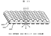
ところで、前記各実施例では、微小レンズを透明ビーズやロッドなど前もって成形された微小体で構成したが、本発明の配光制御素子はこれに限るものではない。即ち、透明基材上に直接、多数の微小レンズを2次元アレイ状に成形したものでもよい。図35はこのような配光制御素子の一例を示す模式斜視図である。この配光制御素子は、例えば、ガラス、無延伸PCフィルム、TACフィルム、射出成形アクリル樹脂板等の光学的に略等方な透明基材3501上に、微小レンズ3502を2次元アレイ状に成形し、さらに、微小レンズ3502の光収束部に開口部を有する黒色の光吸収層(ブラックマトリクス)3503を形成したものである。
By the way, in each said Example, although the microlens was comprised with the micro object shape | molded previously, such as a transparent bead and a rod, the light distribution control element of this invention is not restricted to this. That is, it is possible to form a large number of microlenses in a two-dimensional array directly on a transparent substrate. FIG. 35 is a schematic perspective view showing an example of such a light distribution control element. This light distribution control element is formed, for example, by forming
光吸収層3503は公知の技術、例えば印刷法、蒸着法、フォトリソグラフィー法等により形成することができる。また、微小レンズ3502は公知の技術、例えばポジ型フォトレジストをパターン露光し、現像して円柱状の立体形状を得た後、加熱溶融時の表面張力によりドーム状微小レンズを形成する方法や、光線または電子線の照射により硬化する透明な樹脂膜を透明基材3501上に形成し、これに光線あるいは電子線を選択照射して硬化させ、未硬化部分を除去する方法で形成することができる。
The
いずれの場合も透明基材3501には、光学的に略等方な透明体、または、一軸光学異方性を有する透明体を用いることで、偏光入射時の縞模様の発生と云う問題を解決することができる。
In any case, the
〔背面投射型表示装置の実施例1〕
次に本発明の配光制御素子を用いた背面投射型表示装置について説明する。図11は背面投射型表示装置の模式断面図である。
[
Next, a rear projection display device using the light distribution control element of the present invention will be described. FIG. 11 is a schematic cross-sectional view of a rear projection display device.
本発明の投射型表示装置は、図11に示すとおり、投射装置701からの投射光704が、ミラー702を介して透過型スクリーン703に照射され、画像が表示される。ミラー702としては、光学的に等方な透明ガラスに銀,アルミニウム等の反射性金属を蒸着したものを用いた。
In the projection display device of the present invention, as shown in FIG. 11, the projection light 704 from the
投射装置701としては、いわゆる液晶プロジェクタを用いることができる。図12は液晶プロジェクタの一例を示す模式断面図である。
As the
光源801は回転放物面、または、回転楕円面のリフレクタと、キセノンランプ、メタルハライドランプ、ハロゲンランプ等の白色光源から構成されており、これから出射した光はUV,IRカットフィルタ(図示省略)等を通過することで、紫外線や赤外線が取り除かれた白色光となって、色分離ダイクロイックミラー802に向かう。
The
色分離ダイクロイックミラー802に入射した白色光は、青色光(B)とそれ以外の光に分離され、青色光(B)は全反射ミラー804で反射して、液晶表示素子807に至る。
White light incident on the color separation
一方、色分離ダイクロイックミラー802で反射した緑色光(G)と赤色光(R)は色分離ダイクロイックミラー803で分離され、緑色光(G)は液晶表示素子809へ、また、赤色光(R)は全反射ミラー805,806で反射されて、液晶表示素子808に至る。液晶表示素子807、808、809としては、TN液晶表示素子を用いることができる。
On the other hand, the green light (G) and the red light (R) reflected by the color separation
図13はTN液晶表示素子の一例を示す模式断面図である。この液晶表示素子は、ITO(Indium Tin Oxide)から成る透明電極903,ポリイミド系高分子からなる配光膜905を有する第1の透明ガラス基板901と、配光膜906,画素を形成する透明電極904、これと接続される図示しない配線や薄膜トランジスタ等のスイッチング素子を有する第2の透明ガラス基板902と、シール剤908を介して接着された2枚の透明ガラス基板901と902との間に、封入された誘電異方性が正のネマチック液晶からなる液晶層907とを有する。
FIG. 13 is a schematic cross-sectional view showing an example of a TN liquid crystal display element. This liquid crystal display element includes a
液晶層907の液晶分子長軸の方向は2枚の透明ガラス基板901、902に形成された配光膜905、906にラビング処理することで配向方向が規定され、透明ガラス基板間で連続的に90°捻じれた状態となっている。
The direction of the major axis of the liquid crystal molecules of the
液晶表示素子の光入射面と光出射面には、それぞれ偏光子909、検光子910が互いに直交する直線偏光を透過するように配置され、透明ガラス基板901,902での液晶層907の液晶分子長軸の配向方向は、それぞれ偏光子909および検光子910の直線偏光の透過軸に対して共に平行、もしくは、共に直交するよう構成されている。
A
偏光子909と検光子910は、延伸したポリビニルアルコール(PVA)にヨウ素を吸収させて偏光機能を付与した膜の両面にトリアセチルセルロース(TAC)保護層を施したものを用い、それぞれ透明ガラス基板901および透明ガラス基板902にアクリル系の接着剤により光学的に結合されるよう接着されている。
A
ここで液晶表示素子の動作を説明する。液晶表示素子に入射し偏光子909を透過した直線偏光は、液晶層907を透過して検光子910に入射する。この際、液晶層907を透過する光の偏光状態は、液晶層907に印加される電界によって変化するため、画像情報に対応した電圧を透明電極905および透明電極904に印加し、液晶層907に電界を印加することで、検光子910を透過する光量を制御して光学画像を形成することができる。
Here, the operation of the liquid crystal display element will be described. The linearly polarized light incident on the liquid crystal display element and transmitted through the
従って、図12の液晶表示素子807、808、809にそれぞれ入射した各色光は、それぞれの画像情報に応じて、空間変調されて出射する。各液晶表示素子で変調された各色光は、後に詳述する偏光状態揃え手段812、813、814を通過して、色合成クロスダイクロイックプリズム811に入射,合成された後、投射レンズ810を介して透過型スクリーン703に投射される。
Accordingly, each color light incident on the liquid
図14は、本発明の背面投射型表示装置の透過型スクリーン703の模式断面図である。
FIG. 14 is a schematic cross-sectional view of a
透過型スクリーン703は、フレネルレンズシート801と、本発明の配光制御素子100とから構成される。フレネルレンズ801は凸レンズと同様な作用をする光学部品であり、投射装置701から出射する拡散投射光を平行化し、配光制御素子100へ入射する光の入射角度を0度またはその近傍に変換する働きをする。
The
ここで、本発明の配光制御素子100はその構成上、入射角度が大きくなると透過率が下がると云う性質を有する。図15は入射角度増大に基づく透過率の低下を説明する模式図である。
Here, the light
光の入射角度θが大きくなると、入射光106が透明ビーズ105により収束し、発散しながら透明基材101から出射するが、その際に透明基材101と空気との界面への入射角度が大きくなるため反射が増大して、透過率が著しく低下する。さらに、入射角度θが大きくなると、透明ビーズ101に入射し、収束した光は、配光制御素子100の開口部、即ち、透明ビーズ105と透明接着剤層102の接触部分を通過できず、着色接着剤層103で吸収されてその透過率は低下する。
When the incident angle θ of light increases, the
図16は配光制御素子100の光の入射角度と透過率の関係の一例のグラフである。横軸が光の入射角度θ、縦軸が入射角度θ=0°における透過率を1とした相対透過率である。
FIG. 16 is a graph showing an example of the relationship between the incident angle of light and the transmittance of the light
入射角度θが10°を超えると透過率は急激に低下する。従って、配光制御素子100に入射する光の広がりは、小さければ小さいほど良く、実用的には半値角で±10°以内にすることが望ましい。
When the incident angle θ exceeds 10 °, the transmittance rapidly decreases. Therefore, the spread of light incident on the light
従って、本配光制御素子を従来の例えばR,G,Bの3原色に対応するCRT投射管を3本使用する3管式投射装置を用いた、背面投射型表示装置の透過型スクリーンに用いると、配光制御素子へ入射する各色光の入射角度が異なるため、各色光の透過率が異なり、ホワイトバランスが悪くなったり、強いカラーシフトが現れると云う問題を生じる。 Therefore, this light distribution control element is used for a transmission screen of a rear projection display device using a conventional three-tube projection device using three CRT projection tubes corresponding to, for example, the three primary colors R, G, and B. In addition, since the incident angles of the respective color lights incident on the light distribution control element are different, there is a problem that the transmittance of each color light is different, white balance is deteriorated, and a strong color shift appears.
このため、本発明の背面投射型表示装置では、使用する投射装置としては単管式の投射装置を用いることを特徴としている。単管式では、各色光の透過型スクリーンへの入射角度は一致しているため、上記のホワイトバランスの低下や、カラーシフトが生じると云うようなことはない。 For this reason, the rear projection display device of the present invention is characterized in that a single-tube projection device is used as the projection device to be used. In the single tube system, the incident angles of the light beams of the respective colors to the transmissive screen coincide with each other. Therefore, the above-described white balance is not lowered and the color shift is not caused.
さらに透過型スクリーン703を構成する配光制御素子100の光入射側にはフレネルレンズ801を配置して、投射装置701からの発散投射光704を平行化し、配光制御素子100への入射光の入射角度を実質的に0度に変換することで、配光制御素子100での透過率低下が抑制され、表示画像の輝度を向上することができる。
Further, a
ここで、投射装置701の2次元光学スイッチ素子として用いたTN液晶表示素子は、一般に、コントラスト比の水平方向の対称性を確保するため、偏光子909および検光子910の直線偏光の透過軸が、液晶表示素子の表示面水平方向に対して45°あるいは135°の角度を成すように配置する。この場合、液晶表示素子807、808、809として同じ構成の液晶表示素子を用いると、液晶表示素子を透過した画像光は、色合成クロスダイクロイックプリズム811において、1回反射した画像光と1回も反射しない画像光とで、直線偏光の電気ベクトルの振動方向(以下、直線偏光の振動方向)が異なることになる。
Here, the TN liquid crystal display element used as the two-dimensional optical switch element of the
つまり、液晶表示素子807と808を通過した赤色光(R)および青色光(B)は、色合成クロスダイクロイックプリズム811において各々一回反射するため直線偏光の振動方向は同じだが、液晶表示素子809を通過した緑色光(G)は色合成クロスダイクロイックプリズム811において一度も反射していないために、直線偏光の振動方向が他の色光の直線偏光の振動方向と直交することになる。
That is, since the red light (R) and the blue light (B) that have passed through the liquid
上記のとおり、本発明の配光制御素子100の出射特性は、入射光の偏光状態に依存して変化する。このため、従来の背面投射型表示装置の透過型スクリーンとして、本発明の配光制御素子を用いた場合、ある方向から観察すると画像は緑色を呈し、また、これとは逆の斜め方向から観察すると画像はマゼンタ色を呈することになる。
As described above, the emission characteristics of the light
これを是正するため、本発明の背面投射型表示装置701では、液晶表示素子807、808、809の光出射側に偏光状態揃え手段812、813、814を配置したことを特徴とする。
In order to correct this, the rear
偏光状態揃え手段812、813、814は、液晶表示素子から出射した各色光が、透過型スクリーン703に投射される前に、各色光の偏光状態を一致させる機能を有するものである。
The polarization state aligning means 812, 813, and 814 have a function of matching the polarization state of each color light before the color light emitted from the liquid crystal display element is projected onto the
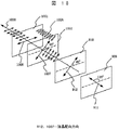
図17は偏光状態揃え手段の一例を示す模式断面図である。この偏光状態揃え手段はポリイミド系の配向膜1003が形成された透明基板1001と、同じくポリイミド系の配向膜1004が形成された透明基板1002と、これら2枚の透明基板の間に封入したネマチック液晶からなる液晶層1006とから構成される。2枚の透明基板1001、1002の間には図示しないスペーサーによって間隙が確保され、周囲をシール剤1005でシールすることで2枚の透明基板を接着し、液晶の密閉を行なっている。
FIG. 17 is a schematic cross-sectional view showing an example of the polarization state aligning means. The polarization alignment means includes a
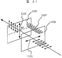
図18は、偏光状態揃え手段の動作を説明するもので、説明を分かり易くするために、液晶表示素子および偏光状態揃え手段の透明基板近傍での液晶分子長軸の配向方向をそれぞれ矢印911、912、1007、1008で示している。
FIG. 18 illustrates the operation of the polarization state aligning means. For easy understanding, the orientation directions of the liquid crystal molecule major axes in the vicinity of the transparent substrate of the liquid crystal display element and the polarization state aligning means are indicated by
図18に例示するとおり、偏光状態揃え手段の液晶層1006は、2枚の透明基板1001と1002上の配向膜により、液晶分子長軸が2枚の透明基板間で45°捩じれており、透明基板1001側の液晶配向方向1008は、液晶表示素子の表示面に対して水平方向となっている。
As illustrated in FIG. 18, the
一方、液晶表示素子側の透明基板1002側の液晶配向方向1007は、液晶表示素子の光出射側の透明基板910の液晶配向方向912と平行となっており、液晶表示素子の表示面水平方向に対して45°傾いている。
On the other hand, the liquid
この偏光状態揃え手段は、入射する光の主波長領域に対してウエーブガイドの条件を満足するように構成される。ウエーブガイドの条件は、例えば、J.Phys.D:Appl.Phys.Vol.8(1975)の1575〜1584頁のC.H.GoochとH.A.Tarryによる論文に記載されている。 This polarization state aligning means is configured to satisfy the conditions of the wave guide for the main wavelength region of incident light. Wave guide conditions are described, for example, in a paper by C. H. Gooch and H. A. Tarry on pages 1575-1584 of J. Phys. D: Appl. Phys. Vol. 8 (1975).
即ち、波長λの光をウエーブガイドにより45°だけ旋光するには、偏光状態揃え手段の液晶層1006の層厚d、波長λにおける複屈折Δnを式(1)を満足するように設定すればよい。
〔数1〕
4d・Δn/λ=V(4m2−1) …(1)
ここで、mは任意の整数である。
That is, in order to rotate the light of wavelength λ by 45 ° by the wave guide, the layer thickness d of the
[Equation 1]
4d · Δn / λ = V (4m 2 −1) (1)
Here, m is an arbitrary integer.
従って、偏光状態揃え手段812、813、814のdとΔnは、これらに入射する光の主波長に対して式(1)を満足する様に設定すればよく、ここでは偏光状態揃え手段812、813、814に入射する光の主波長をそれぞれ450nm、650nn、550nmとし、さらにm=4として、d・Δnがそれぞれ626nm、903nm、765nmとなる様にした。 Therefore, d and Δn of the polarization state alignment means 812, 813, 814 may be set so as to satisfy the expression (1) with respect to the principal wavelength of light incident thereon, and here, the polarization state alignment means 812, The main wavelengths of light incident on 813 and 814 are 450 nm, 650 nn, and 550 nm, respectively, and m = 4, so that d · Δn is 626 nm, 903 nm, and 765 nm, respectively.
なお、ウエーブガイドの条件は、異常光モードと常光モードでは変わらないので、偏光状態揃え手段の液晶の配向方向は、両透明基板での配向方向を共に図18に例示した配向方向に対して90°回転したものを用いてもよい。 Since the conditions of the wave guide do not change between the extraordinary light mode and the ordinary light mode, the alignment direction of the liquid crystal of the polarization state aligning means is 90 with respect to the alignment direction exemplified in FIG. A rotated one may be used.
このように構成することで、液晶表示素子807、808、809を通過した直線偏光はそれぞれ偏光状態揃え手段812、813、814を通過する際、その電気ベクトルの振動方向が45°回転することで、各色光の偏光の状態が、液晶表示素子の表示面に対して水平方向の振動方向を有する直線偏光となり、全て一致することになる。
With this configuration, when the linearly polarized light that has passed through the liquid
また、本実施例の様に、各色光の直線偏光の振動方向を表示面に対して水平方向とすることで以下の効果が得られる。 Moreover, the following effects are acquired by making the vibration direction of the linearly polarized light of each color light into a horizontal direction with respect to a display surface like a present Example.
一般に複数の2次元光学スイッチ素子を用いた単管式の投射装置では、各2次元光学スイッチ素子で形成された光学画像光を合成するためにクロスダイクロイックプリズム、あるいは、ダイクロイックミラーを用いる。 In general, in a single-tube projection apparatus using a plurality of two-dimensional optical switch elements, a cross dichroic prism or a dichroic mirror is used to synthesize optical image light formed by the two-dimensional optical switch elements.
ダイクロイックプリズム、あるいは、ダイクロイックミラーの反射面は誘電体多層膜により形成されており、これに斜めに入射する直線偏光は、入射面に対して平行なp偏光、あるいは、入射面に対して垂直なs偏光以外の場合には、反射の際に偏光状態が変わり、一般に楕円偏光となって、各色光で偏光状態が異なってしまう。しかし、上記のとおり各色光の直線偏光の振動方向を表示面に対して水平方向、即ち、色合成ダイクロイックプリズムの反射面に対してp偏光として入射すれば、各色光の偏光状態は変化せず、全ての各色光の偏光状態が一致したまま、光学画像光を透過型スクリーンへ投射することができる。 The reflecting surface of the dichroic prism or dichroic mirror is formed of a dielectric multilayer film, and linearly polarized light incident obliquely thereto is p-polarized parallel to the incident surface or perpendicular to the incident surface. In the case of other than s-polarized light, the polarization state changes upon reflection, generally becomes elliptically polarized light, and the polarization state differs for each color light. However, as described above, if the direction of vibration of the linearly polarized light of each color light is incident in the horizontal direction with respect to the display surface, that is, the p-polarized light on the reflective surface of the color synthesis dichroic prism, the polarization state of each color light does not change. The optical image light can be projected onto the transmission screen while the polarization states of all the color lights are matched.
つまり、本発明の背面表示装置では、投射装置701から投射される各色光の偏光状態が一致しているため、透過型スクリーン703として用いる配光制御素子100の配光特性の偏光依存性による色付きが解消されて、高品位な画像を得ることができると云う効果がある。
That is, in the rear display device of the present invention, since the polarization states of the respective color lights projected from the
また、透過型スクリーン701に入射する投射光が、表示面に対して水平方向の振動方向を有する直線偏光であるので、配光制御素子100の配光特性の偏光依存性により、垂直方向よりも水平方向の視野角を広くすることができる。このことは一般に、表示装置では垂直方向よりも水平方向に、より広い視野角が求められているので限られた光を観察者へ効率よく配分する上で非常に有効である。
Further, since the projection light incident on the
上記構成の背面投射型表示装置を透過型スクリーン703の配光制御素子100として、〔配光制御素子の実施例1〕に例示した配光制御素子100の透明基材101側表面に、厚さ2mmの平坦で透明な光学的に略等方なアクリル板を張り合わせたものを用いて評価したところ、水平方向の視野角±75°、垂直方向の視野角±45°と、両方向共に広い視野角が得られた。さらに、斜め方向から察した際、縞模様や色付きの発生はなかった。
The rear projection display device having the above configuration is used as the light
また、外部から透過型スクリーンへ入射する不要光は、配光制御素子100の着色接着剤層103で吸収されるため、明るい環境下(垂直照度300lx)において、0.5cd/m2と低輝度な黒表示が実現された。
Further, since unnecessary light incident on the transmission screen from the outside is absorbed by the colored
なお、本発明の背面投射型表示装置の偏光状態揃え手段は、液晶表示素子から出射した各色光の偏光状態を一致させる機能を有するものであればよく、上記実施例の他に、例えば、捩じれ構造を有する高分子積層フィルムや1/2波長板を用いることができる。 The polarization state aligning means of the rear projection type display device of the present invention may be any means as long as it has a function of matching the polarization state of each color light emitted from the liquid crystal display element. A polymer laminated film having a structure or a half-wave plate can be used.
偏光状態揃え手段として用いる捩じれ構造を有する高分子積層フィルムは、例えば位相差d・Δn=275nmのPCフィルム製の位相差フィルムを4枚積層することで実現される。4枚の位相差フィルムは、液晶表示素子に近い方からそれぞれの遅相軸が、液晶表示素子の光出射側の透明基板の液晶配向方向に対して5.6°、16.9°、28.1°、39.4°となるように配置する。この場合も上記実施例と同様な効果が得られる。 The polymer laminated film having a twisted structure used as the polarization state aligning means is realized by laminating four retardation films made of a PC film having a retardation d · Δn = 275 nm, for example. In the four retardation films, the slow axes from the side closer to the liquid crystal display element are 5.6 °, 16.9 °, 28 with respect to the liquid crystal alignment direction of the transparent substrate on the light emission side of the liquid crystal display element. It arrange | positions so that it may become 0.1 degree and 39.4 degree. In this case, the same effect as in the above embodiment can be obtained.
また、偏光状態揃え手段として1/2波長板を用いる場合は、各液晶表示素子を通過した光の波長に対し1/2波長板として機能する波長板の遅相軸を、液晶表示素子の検光子の透過軸に対して22.5°傾けた状態で配置することで上記実施例と同様な効果が得られる。 In addition, when a half-wave plate is used as the polarization alignment means, the slow axis of the wave plate that functions as a half-wave plate with respect to the wavelength of light that has passed through each liquid crystal display element is detected on the liquid crystal display element. The same effect as in the above embodiment can be obtained by placing the photon at 22.5 ° with respect to the transmission axis of the photon.
さらに、出射する直線偏光の振動方向が、他のものとは異なる液晶表示素子の光出射側にのみ、偏光状態揃え手段として1/2波長板を配置して、他の液晶表示素子の偏光状態と一致させるだけでも、斜め方向から観察した際の色付きを、ある程度防止することができる。 Furthermore, a half-wave plate is disposed as a polarization state aligning means only on the light exit side of a liquid crystal display element in which the direction of oscillation of the emitted linearly polarized light is different from that of other liquid crystal display elements, and the polarization state of other liquid crystal display elements Can be prevented to some extent from being colored when observed from an oblique direction.
なお、上記実施例では、液晶表示装置の検光子の直線偏光の透過軸が、表示面平方向に対して45°傾いた場合について説明したが、例えば、検光子の透過軸が、予め表示面に対して水平方向、あるいは、垂直方向となるように構成した液晶表示素子を用いることで、偏光状態揃え手段の機能を液晶表示素子に兼ね備えることが可能である。この場合は、液晶表示素子から出射した各色光の偏光状態は色合成後も一致しているため、液晶表示素子の光出射側に別の光学素子を配置しなくても上記実施例と同様の効果を得ることが可能である。 In the above-described embodiment, the case where the transmission axis of the linearly polarized light of the analyzer of the liquid crystal display device is inclined by 45 ° with respect to the plane direction of the display surface has been described. For example, the transmission axis of the analyzer is previously set to the display surface. By using a liquid crystal display element configured to be horizontal or vertical with respect to the liquid crystal display element, the function of the polarization state aligning means can be provided in the liquid crystal display element. In this case, since the polarization state of each color light emitted from the liquid crystal display element is the same after the color composition, the same as in the above embodiment, even if another optical element is not disposed on the light emission side of the liquid crystal display element. An effect can be obtained.
しかし、この場合はコントラスト比の水平方向の対称性が崩れるので、F値の高い投射光学系を用いて、コントラスト比の左右の非対称性が認識されない様にするのがよい。 However, in this case, since the symmetry of the contrast ratio in the horizontal direction is lost, it is preferable to use a projection optical system having a high F value so that the left-right asymmetry of the contrast ratio is not recognized.
上記のとおり、本発明の背面投射型表示装置は、透過型スクリーン703を配光制御素子100と、その光入射側に配置したフレネルレンズ801fとで構成した。このため投射装置701からの発散投射光704は、配光制御素子100へ入射する際、フレネルレンズ801fにより平行化され、その入射角度が実質的に0度に変換されるため、配光制御素子100での透過率低下が抑制されて、明るい表示画像が得られる。
As described above, in the rear projection display device of the present invention, the
また、本発明では、投射装置として単管式投射装置を用いることで、配光制御素子100の光学特性により生じるカラーシフトや色付きを抑制して、高品位な画像を得ることができる。
Further, in the present invention, by using a single tube type projection device as the projection device, it is possible to suppress color shift and coloring caused by the optical characteristics of the light
さらに投射装置からの出射光の偏光状態を各色光共に一致させることで、配光制御素子100の配光特性の偏光依存性により生じる斜め方向から観察した際に生じる色付きを解消できると云う効果がある。また、透過型スクリーン703として用いた本発明の配光制御素子100は、どの角度から見ても明るい広い視野角特性を有し、外部不要光による迷光の低減効果が高いため、広視野角、かつ、明るい環境下でも低輝度な黒表示の実現により高いコントラスト比が得られる背面投射型表示装置が実現できると云う効果がある。
Further, by matching the polarization state of the light emitted from the projection device for each color light, there is an effect that it is possible to eliminate coloring that occurs when observed from an oblique direction due to the polarization dependence of the light distribution characteristic of the light
なお、以上述べた背面投射型表示装置では、投射装置に複数の2次元光学スイッチ素子を用いる場合を説明したが、2次元光学スイッチ素子を一つだけ用いる、いわゆる単板式の投射装置を用いてもよい。この場合は、もともと2次元光学スイッチ素子はひとつしかないので、光学画像光の偏光状態は揃えなくとも一義的に決るため、本発明の配光制御素子100の配光特性の偏光依存性により色付きが生じることはない。
In the above-described rear projection display device, the case where a plurality of two-dimensional optical switch elements are used in the projection device has been described. However, a so-called single-plate projection device using only one two-dimensional optical switch element is used. Also good. In this case, since there is originally only one two-dimensional optical switch element, the polarization state of the optical image light is uniquely determined evenly. Therefore, the color distribution is colored by the polarization dependence of the light distribution characteristic of the light
〔背面投射型表示装置の実施例2〕
次に、本発明の他の背面投射型表示装置について説明する。ここで述べる背面投型表示装置は図11を用いて説明した前記実施例と同様、投射装置701、ミラー702、透過型スクリーン703を有し、投射装置701から出射した投射光704がミラー702を介して透過型スクリーン703に照射され、画像が表示されるものであるが、投射装置701の構成が一部異なる。
[
Next, another rear projection type display device of the present invention will be described. The rear throw type display device described here includes a
図19は本実施例の背面投射型表示装置に係る投射装置の模式断面図である。この投射装置は、基本的には図12に例示した投射装置と同様であるが、ここで述べる投射装置701は、投射レンズ801とクロスダイクロイックプリズム811の間に偏光状態変換素子815を配置した点が特徴である。
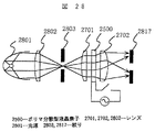
FIG. 19 is a schematic cross-sectional view of a projection apparatus according to the rear projection type display apparatus of the present embodiment. This projection apparatus is basically the same as the projection apparatus illustrated in FIG. 12, except that the
本投射装置では、前記実施例と同様、光源801から出射した白色光は色分離ダイクロイックミラー802および803で青色光(B)と緑色光(G)と赤色光(R)に色分離され、ミラー804、805および806を介して、それぞれ液晶表示素子807、809、808に入射する。液晶表示素子に入射した光はそれぞれ、各色の画像情報に応じて空間変調されて出射し、偏光状態揃え手段812、813、814により各色光は振動方向が一致した直線偏光となって色合成クロスダイクロイックプリズム811に入射する。
In this projection apparatus, as in the above embodiment, the white light emitted from the
この際、色合成クロスダイクロイックプリズム811に入射する各色光は、該プリズム811のミラー面に対してp偏光、あるいは、s偏光とすることが望ましい。なぜなら、色合成プリズム811のミラー面は、誘電体多層膜で構成されており、特別な設計、成膜をしない限り、ミラー面に斜めに入射する直線偏光は、入射面に対して平行なp偏光、あるいは、入射面に対して垂直なs偏光でなければ、反射の際に偏光状態が変わり、一般に楕円偏光となって、各色光の偏光状態が異なってしまうからである。
At this time, each color light incident on the color synthesis cross
ここでは以下画像光が色合成クロスダイクロイックプリズム811のミラー面に対してp偏光、即ち、表示面に対して水平方向に振動方向を有する直線偏光としてプリズム811に入射する場合の例を説明する。
Here, an example in which image light is incident on the
色合成ダイクロイックプリズム811に入射し色合成された画像光は、偏光状態変換素子815および投射レンズ810を介して透過型スクリーン703に投射される。
The image light that has entered the color synthesis
偏光状態変換素子815は、色合成後の画像光の偏光の状態を変えるもので、例えば図20に示す液晶素子を用いることができる。図20に示した偏光状態変換素子815はITOから成る透明電極1103およびポリイミド系高分子からなる配向膜1104が全面的に積層形成された第1の透明ガラス基板1101と、同じく透明電極1105および配向膜1106が全面的に積層形成された第2の透明ガラス基板1102と、2枚の透明ガラス基板1101,1102間に図示しないスペーサーを挟むことで間隙を形成し、その周囲をシール剤1108でシールすることで形成された空間に、封入した誘電異方性が正のネマチック液晶からなる液晶層1107により構成される。
The polarization
液晶層1107の液晶分子長軸は、2枚の透明ガラス基板1101,1102にそれぞれ形成された配向膜1104および1106にラビング処理等の配向処理を行なうことで、両基板間で連続的に90°ねじれた、いわゆるTN液晶素子となっている。
The major axis of liquid crystal molecules of the
次に、偏光状態変換素子815の動作を図面を用いて説明する。図21および図22は偏光状態変換素子815の動作を説明する模式図であり、符号1110および1111で示す矢印は、それぞれ透明ガラス基板1101および1102での液晶の配向方向を示す。
Next, the operation of the polarization
光入射側の透明ガラス基板1102での液晶の配向方向1111は、入射する直線偏光の電気ベクトルの振動方向に平行(もしくは垂直)であり、液晶層1107は可視波長域においてウエーブガイドの条件を満たすものである。
The
従って、偏光状態変換素子815の液晶層1107に電界を印加していないときは図21に例示するとおり、偏光状態変換素子815に入射した光学画像光は、その電気ベクトルの振動方向が90°回転した直線偏光、即ち、表示面に対して垂直方向の振動方向を有する直線偏光となり、投射レンズ810を介して、透過型スクリーン703に投射される。
Therefore, when an electric field is not applied to the
本背面投射型表示装置に用いる透過型スクリーン703は前記実施例と同様、微小レンズとして球状の透明ビーズを用いた配光制御素子と、フレネルレンズから構成される。
The
この場合、上記のとおり、透過型スクリーン703に入射する投射光が、表示面に対して垂直方向の振動方向を有する直線偏光であれば、配光制御素子100の配光特性の偏光依存性により、水平方向よりも垂直方向の視野角が広くなる。
In this case, as described above, if the projection light incident on the
また、図22に例示するとおり、2枚の透明ガラス基板上に形成された透明電極1103および透明電極1105に電圧を印加し、液晶層1107に電界を印加することで、液晶分子をその分子長軸が透明ガラス基板に対してほぼ垂直となるようにすると、偏光状態変換素子815に入射した光学画像光は偏光状態が殆ど変わることなく通過する。即ち、表示面に対して水平方向の振動方向を有する直線偏光のまま、投射レンズ810を介して、透過型スクリーン703に投射される。この場合は透過型スクリーン703を構成する配光制御素子100の配光特性の偏光依存性により、垂直方向よりも水平方向の視野角が広くなる。
In addition, as illustrated in FIG. 22, by applying a voltage to the
即ち、従来の背面投射型表示装置では透過型スクリーンを取り替えなければその視野角特性を変えることができなかったが、本発明の背面投射型表示装置では、偏光状態変換素子815の液晶層に印加する電界を制御すると云う簡単な操作で、視野角特性を容易に変え得ると云う画期的な効果がある。
That is, in the conventional rear projection display device, the viewing angle characteristics could not be changed unless the transmissive screen was replaced. However, in the rear projection display device of the present invention, it is applied to the liquid crystal layer of the polarization
なお、本発明の背面投射型表示装置の偏光状態変換素子815は、上記TN液晶素子の他にECB(Electrically Controlled Birefringence)液晶素子を用いることができる。この場合、TN液晶素子と異なるのは、液晶層の厚さや液晶分子の配向方向等の液晶層に関する部分だけなので、図20に例示したTN液晶素子の模式断面図を用いて説明する。
In addition, as the polarization
ECB液晶素子から構成される偏光状態変換素子815は、上記TN液晶素子から構成される偏光状態変換素子815と同様、ITOから成る透明電極1103およびポリイミド系高分子からなる配向膜1104が全面的に積層形成された第1の透明ガラス基板1101と、同じく透明電極1105および配向膜1106が全面的に積層形成された第2の透明ガラス基板1102と、2枚の透明ガラス基板間に図示しないスペーサーを挟むことで間隙を形成し、その周囲をシール剤1108で接続することで形成された空間に封入されたネマチック液晶からなる液晶層1107とから構成される。
Similar to the polarization
ネマチック液晶の誘電異方性は正であっても負であっても構わないが、液晶の配向は誘電異方性が正のネマチック液晶の場合はホモジニアス配向とし、誘電異方性が負のネマチック液晶の場合はホメオトロピック配向とする。 The dielectric anisotropy of the nematic liquid crystal may be positive or negative, but the liquid crystal orientation is homogeneous in the case of nematic liquid crystal with positive dielectric anisotropy, and nematic with negative dielectric anisotropy. In the case of liquid crystals, the homeotropic alignment is used.
この際、液晶層1107に電界を印加したときの液晶の配向方向を揃えるため、どちらの場合も1〜4°程度のプレチルト角を付け、液晶の分子長軸の方向が表示面に対して45°の方向となるように配向処理を行なう。
At this time, in order to align the alignment direction of the liquid crystal when an electric field is applied to the
液晶層1107の厚さをd、液晶の屈折率異方性をΔnとした場合、d・Δnはλ/2(λは光学画像光の中心波長)以上となるようにする。
When the thickness of the
このように構成した偏光状態変換素子815では、2枚の透明ガラス基板上に形成された透明電極1103と1105に電圧を印加し、液晶層1107に電界を印加することで、入射する光学画像光に対して液晶層1107の見掛けのd・Δnを0〜λ/2の範囲で制御することができる。
In the polarization
従って、液晶層1107の見掛けのd・Δnが0のときは、偏光状態変換素子815に入射した光学画像光は、偏光状態が殆ど変えられることがなく通過すため、表示面に対して水平方向の振動方向を有する直線偏光のまま透過型スクリーン703に入射する。この場合は、透過型スクリーン703を構成する配光制御素子100の配光特性の偏光依存性により、垂直方向よりも水平方向の視野角が広くなる。
Accordingly, when the apparent d · Δn of the
また、液晶層の見掛けのd・Δnがλ/2のときは、偏光状態変換素子815に入射した画像光は、その電気ベクトルの振動方向が90°回転した直線偏光、即ち、表示面に対して垂直方向の振動方向を有する直線偏光となって透過型スクリーン703に入射する。この場合は配光制御素子100の配光特性の偏光依存性により、水平方向よりも垂直方向の視野角が広くなる。
In addition, when the apparent d · Δn of the liquid crystal layer is λ / 2, the image light incident on the polarization
さらに、液晶層の見掛けのd・Δnがλ/4のときは、偏光状態変換素子815に入射した画像光は略円偏光となって透過型スクリーン703に入射する。この場合は、垂直方向、水平方向共に同程度の等方的な視野角が得られる。
Furthermore, when the apparent d · Δn of the liquid crystal layer is λ / 4, the image light incident on the polarization
ここでECB液晶素子から構成される偏光状態変換素子815の動作を、図23および図24を用いて具体的に説明する。
Here, the operation of the polarization
偏光状態変換素子815の液晶として誘電異方性Δε=−4.2、屈折率異方性Δn=0.083のネマチック液晶を用い、液晶層の厚さを3.5μmとした。配向膜1104および1105は垂直配向性を示すポリイミド系配向膜を用い、表示面水平方向に対して45°の角度を成す方向にラビング処理を行ない、液晶分子に約2°のプレチルトを付与した。
A nematic liquid crystal having a dielectric anisotropy Δε = −4.2 and a refractive index anisotropy Δn = 0.083 was used as the liquid crystal of the polarization
この偏光状態変換素子815の液晶層1107は、電界無印加の場合は、液晶層1107の見掛けのdΔnはほぼ0なので、図23に示する様に、入射した光学画像光は偏光状態が殆ど変えられることなく通過し、投射レンズ810を介して、表示面に対し水平方向の振動方向を有する直線偏光の状態で、透過型スクリーン703に投射される。この場合は透過型スクリーン703を構成する配光制御素子100の配光特性の偏光依存性により、垂直方向よりも水平方向の視野角が広くなる。
Since the apparent dΔn of the
一方、図24に示す様に、2枚の透明ガラス基板上に形成された透明電極に電圧を印加し、液晶層1107に電界を印加することで液晶分子の分子長軸を透明ガラス基板に対して垂直方向から水平方向に傾けて、液晶層1107の見掛けのdΔnが225nmとなるようにすると、偏光状態変換素子815に入射した画像光はその電気ベクトルの振動方向がほぼ90°回転し、表示面に対して垂直方向の振動方向を有する直線偏光、もしくは、表示面に対してほぼ垂直方向に長軸を有する楕円偏光となって透過型スクリーン703に入射する。この場合、透過型スクリーン703を構成する配光制御素子100の配光特性の偏光依存性により、水平方向よりも垂直方向の視野角が広くなる。
On the other hand, as shown in FIG. 24, a voltage is applied to the transparent electrodes formed on the two transparent glass substrates, and an electric field is applied to the
また、偏光状態変換素子815の2枚の透明ガラス基板上に形成された透明電極に電圧を印加し、液晶層1107に電界を印加することで液晶分子の分子長軸を透明ガラス基板に対して垂直方向から水平方向へ傾けて、液晶層の見掛けのdΔnを137.5nmとなるようにすると、偏光状態変換素子815に入射した光学画像光は略円偏光となって透過型スクリーン703に入射する。この場合は透過型スクリーン703を構成する配光制御素子100の特性により、水平方向、垂直方向共に同程度の等方的な視野角が得られる。
In addition, a voltage is applied to the transparent electrodes formed on the two transparent glass substrates of the polarization
即ち、従来の背面投射型表示装置では透過型スクリーンを取り替えなければ、その視野角特性を変えることができなかったが、本背面投射型表示装置では、TN液晶素子、あるいは、ECB液晶素子により構成した偏光状態変換素子815の液晶層に印加する電界を制御することで、水平方向の視野角を広くしたり、垂直方向の視野角を広くしたり、水平方向、垂直方向共に同程度の等方的な視野角が得られるといった様に、容易に視野角特性を変えることができる。
That is, in the conventional rear projection type display device, the viewing angle characteristic cannot be changed unless the transmissive screen is replaced. In this rear projection type display device, the TN liquid crystal element or ECB liquid crystal element is used. By controlling the electric field applied to the liquid crystal layer of the polarization
なお、上記実施例では偏光状態変換素子815として、液晶素子を用いることで視野角特性を可変とする場合について述べたが、この他に、例えば偏光状態変換素子815として位相差板を配置することで、所望の視野角特性を得るようにしてもよい。例えば、偏光状態変換素子815として1/4波長板を配置し、透過型スクリーン703に入射する光学画像光を、円偏光とすることで等方的な視野角を得るようにするなど種々の変形が考えられる。
In the above embodiment, the case where the viewing angle characteristic is made variable by using a liquid crystal element as the polarization
〔背面投射型表示装置の実施例3〕
次に、本発明の他の背面投射型表示装置について説明する。図40は本実施例の背面投射型表示装置の模式構成斜視図である。
[
Next, another rear projection type display device of the present invention will be described. FIG. 40 is a schematic configuration perspective view of the rear projection display device of the present embodiment.
本実施例の背面投射型表示装置は、前記実施例2の背面投射型表示装置に、観察者の有無を感知する観察者感知部4002と、観察者感知部からの感知信号を受信して観察者の水平および垂直方向の位置を判断する観察者位置判断手段(図示省略)と、その情報に基づき投射装置701に配置した偏光状態変換素子に制御信号を出力する制御信号出力手段(図示省略)を付加したものである。
The rear projection type display apparatus of this embodiment receives the observation signal from the
観察者感知部4002は、複数の観察者感知センサーから構成され、これら観察者感知センサーは、区分された複数の領域に存在する観察者をそれぞれ感知する。該観察者感知センサーには赤外線センサーが用いられる。
The
図41および図42は、観察者感知センサーが感知する区分された領域を例示したものである。図41には垂直方向をI,II,IIIの3領域に、また、図42には水平方向をA、B、Cの3領域に区分した場合を示す。この例では、観察者4100を感知するための観察者感知センサーは9つ必要である。
41 and 42 exemplify the divided areas sensed by the observer sensing sensor. 41 shows a case where the vertical direction is divided into three regions I, II and III, and FIG. 42 shows a case where the horizontal direction is divided into three regions A, B and C. In this example, nine observer detection sensors for detecting the
上記の観察者感知部4002に設けた9つの観察者感知センサーが、それぞれ背面投射型表示装置4001の前方で観察する観察者4100を感知し、それぞれの感知信号に基づき観察者位置判断手段が垂直および水平のどの領域(位置)に観察者4100が存在するかを判断する。この観察者位置判断手段の情報に基づき制御信号出力手段が、投射装置701の偏光状態変換素子に制御信号を出力する。
The nine observer detection sensors provided in the
ここで、前記実施例2と同様に、本実施例の背面投射型表示装置は、投射光704の偏光状態を投射装置701内の偏光状態変換素子により変えることで、透過型スクリーン703の視野角特性を変えることができる。即ち、観察者の位置を感知,判断して、偏光状態変換素子を制御し、投射光704の偏光状態を適切な状態に変換することで、観察者に明るい映像を提供することができる。
Here, similarly to the second embodiment, the rear projection display apparatus according to the present embodiment changes the polarization state of the
次に、図43および図44により本背面投射型表示装置の効果を説明する。一般に、背面投射型表示装置では限られた光を観察者方向に有効に配光するため、垂直方向の視野角は、水平方向の視野角よりも狭く設定されており、図43に例示する様にスクリーン703の全面にわたって、均一な明るさの映像が得られる有効範囲は垂直方向では狭くなっている。このため、観察者4100は椅子に座るなどして適切な高さで観察するか、または、一定の距離を保って観察するなどしなければ、良好な画質を得ることができない。
Next, the effect of the rear projection display device will be described with reference to FIGS. 43 and 44. In general, in the rear projection type display device, in order to effectively distribute limited light in the viewer direction, the vertical viewing angle is set narrower than the horizontal viewing angle, as shown in FIG. In addition, the effective range in which an image with uniform brightness can be obtained over the entire surface of the
従って、図43に例示するとおり、観察者4100が椅子に座っているときには良好な映像を観ることができても、立ち上がるとスクリーン703下部の画像は暗くなり良好な映像を観ることができなくなると云った問題があった。
Therefore, as illustrated in FIG. 43, when the
しかし、本背面投射型表示装置では観察者が立ち上がった場合、立ち上がった観察者4102は観察者感知部4002により感知され、この感知信号をもとに観察者の位置は人体位置判断手段により判断される。さらにこの観察者の位置情報をもとに制御信号出力手段が偏光状態変換素子を制御し、投射光の偏光状態を適切な状態に変換することで、図44に例示する様に、垂直方向の視野角を拡大して立ち上がった観察者4102に良好な映像を提供できる。
However, in this rear projection display device, when the observer stands up, the
より具体的には図43に例示する状態では、スクリーン703に投射される投射光をスクリーン703の表示面に対し、水平方向の振動方向を有する直線偏光とすることで、垂直方向よりも水平方向の視野角が広い視野角特性としている。
More specifically, in the state illustrated in FIG. 43, the projection light projected on the
しかし、観察察者が立ち上がった場合には、観察者感知部4002の感知信号をもとに偏光状態変換素子を制御して、投射光をスクリーン703の表示面に対し垂直方向の振動方向を有する直線偏光へ変換することで図44に例示する通り、垂直方向の視野角を広げて観察者4102に良好な映像を提供できる。
However, when the observer stands up, the polarization state conversion element is controlled based on the sensing signal of the
上記の通り、本背面投射型表示装置は、観察者の位置に応じて視野角特性が自動的に変わり、限られた映像光を観察者の方向へ有効に配光できるため、観察者は任意の位置で良好な映像が得られる。 As described above, the rear projection display device automatically changes the viewing angle characteristics according to the position of the observer, and can effectively distribute the limited image light in the direction of the observer. Good images can be obtained at the position.
〔背面投射型表示装置の実施例4〕
次に本発明の他の背面投射型表示装置について説明する。本実施例の背面投型表示装置は、図11を用いて説明した前記実施例と同様であるが、投射装置701に使用される2次元光学スイッチ素子の構成が異なる。
[
Next, another rear projection type display device of the present invention will be described. The back throw type display device of this embodiment is the same as the embodiment described with reference to FIG. 11, but the configuration of the two-dimensional optical switch element used in the
本背面投射型表示装置の特徴は、投射装置701に使用される2次元光学スイッチ素子が、表示に偏光を用いず無偏光の状態で表示を行なうことを特徴とし、これにより透過型スクリーン703を構成する配光制御素子100の透明基材の光学的な異方性による縞模様の発生や、配光制御素子の配光特性の偏光依存性による色度変化といった課題を根本から回避することを特徴とする。
The feature of the rear projection display device is that the two-dimensional optical switch element used in the
表示に偏光を用いない2次元光学スイッチ素子としては種々考えられるが、ここでは、まず、ポリマ分散型液晶素子を散乱型表示素子として用いる場合について説明する。 Various types of two-dimensional optical switch elements that do not use polarized light for display are conceivable. First, a case where a polymer dispersion type liquid crystal element is used as a scattering type display element will be described.
ポリマ分散型液晶としては、マイクロカプセルに入った正の誘電異方性を有するネマチック液晶をポリマ中に分散したもの、ポリママトリクス中に液晶滴を分散したもの、あるいは、液晶連続層中に網目状ポリマを形成したもの等がある。 Polymer dispersed liquid crystals include nematic liquid crystals with positive dielectric anisotropy contained in microcapsules dispersed in a polymer, liquid crystal droplets dispersed in a polymer matrix, or a network in a continuous liquid crystal layer. There are polymers formed.
図25は、ポリマ分散型液晶素子の一例を示す模式断面図である。このポリマ分散型液晶素子2500は、ITOから成る透明電極2503が全面に形成された第1の透明ガラス基板2501と、画素を形成する透明電極2504およびこれと接続される図示しない配線や薄膜トランジスタ等のスイッチング素子を有する第2の透明ガラス基板2502と、シール剤2508を介して接続された2枚の透明ガラス基板2501、2502の間に形成されたポリマ分散液晶層2505とから構成される。
FIG. 25 is a schematic cross-sectional view showing an example of a polymer dispersion type liquid crystal element. The polymer dispersed
ポリマ分散液晶層2505は、ポリビニルアルコール等のポリマ2507中に正の誘電異方性を有する液晶滴2506を分散したもので、液晶の分子短軸方向の屈折率とポリマの屈折率は略一致している。
The polymer-dispersed
図26にポリマ分散型液晶素子の動作を示す。ポリマ分散液晶層2505の液晶は、ポリマ分散液晶層2505に電界が印加されていない場合、液晶がポリマ側壁によるアンカリング、壁面の形状、表面エネルギーなどの影響を受け、不規則に配列している。このため、ポリマ分散液晶層2505は、液晶分子長軸方向の屈折率neから液晶短軸方向の屈折率noまでの屈折率分布を有する微粒子が、屈折率noのポリママトリクス中に浮かんでいることになり、入射した光は屈折率の異なる界面で屈折し、散乱する。
FIG. 26 shows the operation of the polymer dispersion type liquid crystal element. When no electric field is applied to the polymer dispersed
一方、透明ガラス基板2501、2502上の透明電極に電圧を印加して液晶に電界を印加すると、液晶はその分子長軸が透明ガラス基板に対して垂直方向に配列され、光の進行方向からみる液晶の屈折率はnoで一定となり、ポリママトリクスの屈折率と一致する。このため、入射光は液晶とポリマの界面で散乱することなく透過する。
On the other hand, when a voltage is applied to the transparent electrodes on the
このようにポリマ分散型液晶素子では、ポリマ分散液晶層2505への電界の印加/非印加によって光の散乱度合いを変化させることができる。しかし、光の透過量が変化するわけではないので、これを表示に用いるためには光の散乱度合いを光の明暗に変換する光学系が必要となる。よく知られているようにこのような目的にはシュリーレン光学系が用いられる。
Thus, in the polymer dispersion type liquid crystal element, the degree of light scattering can be changed by applying / not applying an electric field to the polymer dispersion
図27および図28はシュリーレン光学系を用いたポリマ分散型液晶素子の表示動作を説明する模式図である。光源2801から出射した略平行光は収束レンズ2802の作用により入射側絞り2803の開口部に収束され、入射側絞り2803の開口部を通過した光はレンズ2701により、再び略平行光となりポリマ分散型液晶素子2500に入射する。図示した様に、ポリマ分散型液晶素子2500のポリマ分散液晶層に、十分な電界が印加されているとポリマ分散型液晶素子2500に入射した光はほぼ平行光のまま透過し、収束レンズ2702で収束され、出射側絞り2817の開口部を通過する。
27 and 28 are schematic views for explaining the display operation of a polymer dispersion type liquid crystal element using a schlieren optical system. The substantially parallel light emitted from the
一方、図28に示すとおり、ポリマ分散型液晶素子2500のポリマ分散液晶層に電界が印加されていないときは、ポリマ分散型液晶素子2500に入射した光は散乱し、出射側絞り2817の開口部をほとんど通過できない。従って、出射側絞り2817を通過する光を表示に用いることで明暗の表示が可能になる。
On the other hand, as shown in FIG. 28, when an electric field is not applied to the polymer dispersed liquid crystal layer of the polymer dispersed
次にポリマ分散型液晶素子を2次元光学スイッチ素子として用いた投射装置について説明する。 Next, a projection apparatus using a polymer dispersion type liquid crystal element as a two-dimensional optical switch element will be described.
図29は、ポリマ分散型液晶素子を用いた投射装置の一例を示す模式断面図である。 FIG. 29 is a schematic cross-sectional view showing an example of a projection apparatus using a polymer dispersion type liquid crystal element.
光源2801は回転放物面形状のリフレクタと、リフレクタの焦点位置に発光部を配置したメタルハライドランプから構成されており、発光部から出射した光の大部分はリフレクタで反射し、略平行光となり出射する。光源2801から出射した光は、UV,IRカットフィルタ(図示省略)を通過することで、紫外線や赤外線が取り除かれた白色光となり、入射側収束レンズ2802の作用により入射側絞り2803の開口部に収束される。
The
上記入射側絞り2803を通過した白色光は、赤色光反射ダイクロイックミラー2804で赤色光成分が反射し、反射した赤色光は全反射ミラー2807を介して、入射側レンズ2812に入射し、該入射側レンズの作用により平行光となってポリマ分散型液晶素子2815に入射する。
The white light that has passed through the incident-
一方、赤色光反射ダイクロイックミラー2804を透過した光の内、緑色光成分は緑色光反射ダイクロイックミラー2805で反射して、入射側レンズ2811に入射し、その作用により平行光となってポリマ分散型液晶素子2814に入射する。
On the other hand, of the light transmitted through the red light reflecting
また、緑色光反射ダイクロイックミラー2805を透過した青色光は、入射側レンズ2810に入射し、その作用により平行光となってポリマ分散型液晶素子2813に入射する。
Further, the blue light transmitted through the green light reflecting
ポリマ分散型液晶素子2813、2814、2815に入射した各色光は、それぞれの画像情報に応じて散乱状態が制御されてポリマ分散型液晶素子から出射する。ポリマ分散型液晶素子2815を通過した赤色光は、緑色光反射ダイクロイックミラー2808および青色光反射ダイクロイックミラー2809を透過して投射レンズ2819に入射する。
Each color light incident on the polymer-dispersed
また、ポリマ分散型液晶素子2814を通過した緑色光は、緑色光反射ダイクロイックミラー2808で反射して、赤色光と合成され、青色光反射ダイクロイックミラー2809を透過して投射レンズ2819に入射する。ポリマ分散型液晶素子2813を通過した青色光は全反射ミラー2806および青緑色光反射ダイクロイックミラー2809で反射して、赤色光および緑色光と合成されて投射レンズ2819に入射する。
Further, the green light that has passed through the polymer dispersion type
投射レンズ2819は、後群レンズ2816および前群レンズ2818とこれらの間に配置された出射側絞り2817から構成される。
The
投射レンズ2819の後群レンズ2816と、前記入射側レンズ2810、2811および2812は、投射レンズの出射側絞り2817と、前記入射側絞り2803を互いに共役な関係としている。このため投射レンズ2819に入射した光の内、ポリマ分散型液晶素子2813、2814、2815において散乱作用を受けなかった画素の光は、出射側絞り2817を通過して明表示となる。
The
一方、ポリマ分散型液晶素子2813、2814、2815において散乱作用を受けた画素の光は、その一部、または、ほとんどが出射側絞り2817を通過できないため暗表示となる。
On the other hand, part or most of the pixel light subjected to the scattering action in the polymer dispersion type
このように本投射装置から投射される光学画像光は、表示に偏光を利用しないため略無偏光の状態である。つまり、透過型スクリーン703に入射する光学画像光は無偏光であるため、それを構成する配光制御素子100の透明基材に複屈折性があっても、透明基材の光学的な異方性による縞模様の発生や、配光制御素子の配光特性の偏光依存性による色度変化と云った問題は回避される。つまり、配光制御素子の透明基材として、光学異方性のある透明体を用いてもよいので材料選択範囲が広く、従ってより安価で高強度の材料を用いることが可能となる。
Thus, the optical image light projected from the projection apparatus is in a substantially non-polarized state because polarized light is not used for display. That is, since the optical image light incident on the
上記により、複屈折性の小さいフィルム、例えば、TACフィルムのように高価で、強度の弱いフィルムの代わりに、2軸延伸したPETフィルムのように安価で高強度のフィルムを配光制御素子の部材として用いることができ、背面投射型表示装置の透過型スクリーンを低コストで実現できる。 According to the above, instead of an expensive film with low birefringence, for example, an expensive film with low strength such as a TAC film, an inexpensive and high strength film such as a biaxially stretched PET film is used as a member of a light distribution control element. The transmission screen of the rear projection display device can be realized at low cost.
ここで、本実施例に用いる配光制御素子100について説明する。本配光制御素子100は図1および図2に例示したものと同様な構成となっている。透明基材101には厚さ120μmの平坦な2軸延伸したPETフィルムを用いた。2軸延伸フィルムは、無延伸フィルムに比べて引張り強さや衝撃強さが増大し、透明性、使用温度範囲等の物性も著しく向上している。
Here, the light
本配光制御素子100は以下に述べる方法で作製した。透明基材101の表面にポリエステル系ホットメルト接着剤からなる透明接着剤層を5μm、その上に同じくポリエステル系ホットメルト接着剤にカーボンブラックを10重量部配合した着色接着剤層を4.5μmを形成し、一旦、固化する。
This light
その上に屈折率が1.935(波長589.3nm)、直径が50μmの球体状のガラス製透明ビーズを密に分散配置し、恒温槽中で透明接着剤層および着色接着剤層を軟化させつつ、加圧板により透明ビーズを透明基材側へ加圧して該ビーズを接着剤層に埋没,固着する。透明ビーズ固着後の接着層の厚さは透明接着剤層と着色接着剤層合わせて約21μmであり、透明ビーズはその直径の約58%が接着剤層から露出していた。 On top of that, spherical glass beads having a refractive index of 1.935 (wavelength: 589.3 nm) and a diameter of 50 μm are densely dispersed to soften the transparent adhesive layer and the colored adhesive layer in a thermostatic bath. Meanwhile, the transparent beads are pressed toward the transparent substrate by a pressure plate, and the beads are buried and fixed in the adhesive layer. The thickness of the adhesive layer after fixing the transparent beads was about 21 μm for both the transparent adhesive layer and the colored adhesive layer, and about 58% of the diameter of the transparent beads was exposed from the adhesive layer.
この配光制御素子100の透明基材101側表面に、厚さ2mmの平坦で透明な光学的に等方なアクリル板を貼り合わせ、さらに透明ビーズ105側にフレネルレンズを配置して透過型スクリーン703としたものを2次元光学スイッチ素子として、ポリマ分散型液晶素子を用いた投射装置701およびミラー702と組み合わせ図11に示す様な背面投射型表示装置を実現した。
A transparent and transparent optically isotropic acrylic plate having a thickness of 2 mm is bonded to the surface of the light
この背面投射型表示装置を評価したところ、投射装置701から投射される各色光の偏光状態は無偏光で一致しており、透過型スクリーン703を構成する配光制御素子100の配光特性の偏光依存性による色付きや、縞模様のない高品位な画像を得ることができた。また、水平方向、垂直方向共に±60°と広く、等方的な視野角が得られた。
When this rear projection type display device was evaluated, the polarization state of each color light projected from the
さらに、外部から透過型スクリーンへ入射する不要光は、配光制御素子の着色接着剤層で吸収されるため、明るい環境下(垂直照度300lx)において、0.5cd/m2と低輝度な黒表示が実現され、明るい環境下でも高いコントラスト比が得られた。 Furthermore, since unnecessary light incident on the transmission screen from the outside is absorbed by the colored adhesive layer of the light distribution control element, the black light having a low luminance of 0.5 cd / m 2 in a bright environment (vertical illuminance 300 lx). The display was realized and a high contrast ratio was obtained even in a bright environment.
なお、表示に偏光を用いない2次元光学スイッチ素子としては、米国特許第5061049号、同第5083857号、または、米国特許出願08/161832および米国特許出願08/171303等に記載されているディジタルミラーデバイス(DMD)を用いることができる。 Note that as a two-dimensional optical switch element that does not use polarized light for display, US Pat. Nos. 5,610,409 and 5,083,857, or digital mirrors described in US patent application 08/161832, US patent application 08/171303, etc. A device (DMD) can be used.
上記DMDは、半導体基板上に捻じれヒンジにより支持された画素に相当する微小ミラーのアレーと、アドレス電極とを有しており、アドレス電極に電圧が印加されると微小ミラーが静電吸引力により偏向、または、回転するものである。 The DMD has an array of micromirrors corresponding to pixels twisted on a semiconductor substrate and supported by hinges, and an address electrode. When a voltage is applied to the address electrode, the micromirror is electrostatically attracted. Is to be deflected or rotated.
従って、入射光を投射レンズに向けて反射すると明表示、入射光を光吸収手段に向けて反射すると暗表示となる。即ち、無偏光で表示を行なうことができるので、ポリマ分散型液晶素子を用いた背面投射型表示装置と同様、透過型スクリーンとして用いる配光制御素子の透明基材が、光学的に異方性であっても配光特性の偏光依存性による色付きや、縞模様のない高品位な画像を得ることができる。 Accordingly, when the incident light is reflected toward the projection lens, a bright display is obtained, and when the incident light is reflected toward the light absorbing means, a dark display is obtained. That is, since non-polarized light can be displayed, the transparent base material of the light distribution control element used as the transmissive screen is optically anisotropic as in the rear projection display device using the polymer dispersion type liquid crystal element. Even so, it is possible to obtain a high-quality image without coloring due to the polarization dependency of the light distribution characteristic or without a stripe pattern.
〔背面投射型表示装置の実施例5〕
次に本発明の他の背面投射型表示装置について説明する。ここで述べる背面投型表示装置は図11を用いて説明した上記実施例と同様、投射装置701、ミラー702、透過型スクリーン703を有し、投射装置701から出射した投射光704がミラー702を介して透過型スクリーン703に照射され、画像が表示されるものであるが、投射装置701の構成が異なる。
[Embodiment 5 of rear projection display device]
Next, another rear projection type display device of the present invention will be described. The rear projection display device described here includes a
本発明の要点の一つは、透過型スクリーン703を構成する配光制御素子100に入射する画像光を、概ね無偏光とすることにある。従って、本実施例では2次元光学スイッチ素子として、無偏光で表示可能な表示素子を用いる他に、配光制御素子と2次元光学スイッチ素子との間に、偏光を解消する偏光解消手段を配置することでこれを実現した。
One of the main points of the present invention is that image light incident on the light
偏光解消手段としては波長幅、時間などの積分範囲内でいろいろな偏光を人為的に作り、これらを混合平均化することで位相の面で概ね無偏光を作る素子、いわゆる、擬似デポラライザーを用いることができる。 As the depolarization means, an element that artificially creates various polarized light within the integration range such as wavelength width and time, and averages these to produce non-polarized light in terms of phase, so-called pseudo depolarizer is used. be able to.
該デポラライザーとしては、例えば、光学軸に平行に切出し研磨した、屈折率異方性Δn=0.009で、厚さ2mmと厚さ1mmの水晶板を、遅相軸が互いに45°を成すように組み合わせたLyotのデポラライザーを用いることができる。このデポラライザーを用いれば、白色光に対してほぼ完全なデポラライザーとなる。また、膜厚をd、屈折率異方性をΔnとしたときd・Δnを可視波長に対して十分大きくした高分子液晶フィルムや位相差フィルムを積層したもので、同様に擬似デポラライザーを構成してもよい。 As the depolarizer, for example, a quartz plate having a refractive index anisotropy Δn = 0.09, a thickness of 2 mm and a thickness of 1 mm, cut and polished parallel to the optical axis, and the slow axes of 45 ° each other is formed. A Lyot depolarizer combined as described above can be used. If this depolarizer is used, it becomes a substantially complete depolarizer for white light. In addition, a polymer liquid crystal film or a retardation film in which d · Δn is sufficiently larger than the visible wavelength when the film thickness is d and the refractive index anisotropy is Δn are laminated, and the pseudo depolarizer is similarly configured. May be.
このような擬似デポラライザーは、例えば、図30に示す投射装置のように、2次元光学スイッチ素子807、808、809を通過した光が色合成された後の光路中に配置するとよい。図30は上記実施例で説明したTN液晶表示素子を用いた投射装置に、擬似デポラライザー3000を新たに配置したものである。これによって、偏光がほぼ解消された光学画像光を透過型スクリーン703に投射することができる。
Such a pseudo depolarizer is preferably disposed in the optical path after the light that has passed through the two-dimensional
つまり、投射装置701から投射される各色光の偏光状態は、概ね無偏光となり一致しているため、配光制御素子100の配光特性の偏光依存性による色付きや、縞模様のない高品位な画像を得ることができる。さらに、配光制御素子100の透明基材101として光学異方性のある透明体を用いてもよいため、透明基材101の材料選択範囲が広くなり、より安価で強度の高い材料を用いることが可能となる。 なお、以上述べた背面投射型表示装置ではその投射装置の2次元光学スイッチ素子として、透過型の液晶表示素子を用いたものについて説明してきたが、これに限定されず、反射型の表示素子であってもよい。
That is, since the polarization state of each color light projected from the
また、表示モードもTNモードに限らず、VA(Vertical Aligned)モードや、ECBモード、OCBモード、STN(Super Twisted Nematic)モード等の液晶表示素子、強誘電液晶や反強誘電液晶を用いた液晶表示素子であってもよい。 In addition, the display mode is not limited to the TN mode, but a liquid crystal display element such as a VA (Vertical Aligned) mode, an ECB mode, an OCB mode, an STN (Super Twisted Nematic) mode, or a liquid crystal using a ferroelectric liquid crystal or an antiferroelectric liquid crystal. It may be a display element.
〔液晶表示装置の実施例1〕
図31は、本発明に係る配光制御素子を用いた直視型の液晶表示装置の模式断面図である。
[Example 1 of liquid crystal display device]
FIG. 31 is a schematic cross-sectional view of a direct-view liquid crystal display device using the light distribution control element according to the present invention.
本発明の液晶表示装置は、液晶表示素子1302と、その背面に設けられたバックライト装置1301と、液晶表示素子1302の背面と前面とにそれぞれ配置された偏光子1204および検光子1214と、検光子1214の前面に設けられた本発明の配光制御素子100とから構成される。
The liquid crystal display device of the present invention includes a liquid
バックライト装置1301は、略平行な光を効率よく出射できるものであり、例えば、特表平9−505412号公報や、国際公開番号WO95/14255に記載の「電子光学ディスプレイ用のバックライト組み立て体」を用いることができる。
The
ここでは冷陰極管からなる光源1201と、透明なアクリル樹脂から構成される導光体1202と、光平行化手段1203から構成されるバックライト装置を用いた。
Here, a
光平行化手段1203としては、公知の素子、例えば、図31に示した導光体1202に光学的に結合された4角錐状のマイクロテーパーロッド配列を用いることができる。この場合、導光体1202から導かれた光は、マイクロテーパーロッドの壁面で一回以上全反射し、略平行化されて出射する。
As the light collimating means 1203, a known element, for example, a quadrangular pyramidal microtaper rod array optically coupled to the
光平行化手段1203としては、この他にマイクロプリズムシートや、マイクロレンズ配列を用いることができる。このような光平行化素子1203を有するバックライト装置を用いることで半値角で±10°以内の略平行化された照明光が得られる。
As the light collimating means 1203, a microprism sheet or a microlens array can be used. By using a backlight device having such a
液晶表示素子1302は、ITOから成る透明電極1212およびポリイミド系高分子からなる配向膜1211を有する第1の透明基板1210と、配向膜1207と、画素を形成する透明電極1206、および、これと接続される図示しない配線や薄膜トランジスタ等のスイッチング素子を有する第2の透明基板1205と、シール剤1208を介して接続された2枚の透明基板1212、1210の間に封入された誘電異方性が正のネマチック液晶からなる液晶層1209とを有する。
The liquid
液晶表示素子1302は、2枚の透明基板1205および1210に施された配向膜1207および1211に、ラビング処理を行うことで液晶層1209の液晶分子長軸が2枚の透明基板間で連続的に90°捻じれた、いわゆるTN液晶表示素子を構成している。
In the liquid
上記液晶表示素子1302の光入射面と光出射面には、それぞれ偏光子1204および検光子1214が、互いに直交する直線偏光を透過するように配置される。偏光子1204および検光子1214としては、延伸したPVAにヨウ素を吸収させて偏光機能を付与した膜の両面にTAC保護層を施したものを用い、それぞれ透明基板1205および透明基板1210にアクリル系の接着剤で、光学的に結合されるよう接着される。
A
検光子1214の前面には、配光制御素子100が配置される。配光制御素子100としては、配光制御素子の実施例1で説明した素子を用いた。検光子1214との接着は、ここでは液晶表示素子の表示部を取り囲むようにパターニングされた接着剤1213により行なったが、配光制御素子100の透明ビーズと検光子1214との隙間を、その全面にわたって屈折率の低い透明な接着剤で埋めるように接着するか、これらの併用であってもよい。
A light
次に、上記直視型液晶表示装置の動作についてを説明する。バックライト装置1301からの出射光1215の内、偏光子1204を透過した直線偏光は、液晶パネル1302を透過して検光子1214に入射する。この際、液晶パネル1302を透過する光の偏光状態は、液晶層1209に印加される電界によって変化するため、液晶層1209に画像情報に対応した電界を印加することで、検光子1214を透過する光量を制御して画像を形成することができる。検光子1214を透過した画像光は配光制御素子100に入射する。
Next, the operation of the direct view liquid crystal display device will be described. Of the outgoing light 1215 from the
配光制御素子100に入射した光はその大部分が配光制御素子100の透明ビーズに入射し、その屈折作用により収束し、発散する。
Most of the light incident on the light
ここで、一般のTN液晶表示装置には視野角依存性があり、斜め方向から観察するとコントラスト比の低下、階調反転、色調変化が起こる。従って、良好な画質が得られるのは正面近傍の範囲に限られる。 Here, a general TN liquid crystal display device has a viewing angle dependency, and when viewed from an oblique direction, a contrast ratio is lowered, gradation inversion, and color tone change occur. Therefore, good image quality can be obtained only in the vicinity of the front.
また、配光制御素子100は上記のとおり、入射光の入射角度が大きくなると着色接着剤層での吸収により透過率が低くなる。このため液晶表示素子1302から出射する光の内、コントラスト比の低下や階調反転、色調変化が起こるような入射角度の大きな光は、着色接着剤層で大部分が吸収される。
Further, as described above, the light
一方、良好な画質が得られる実質的に入射角度0°の正面近傍の光は透過し、等方的に拡散されるため、広い視野角範囲で色調変化や階調反転がなく、コントラスト比の高い画像が得られる。 On the other hand, light in the vicinity of the front with an incident angle of 0 °, which provides good image quality, is transmitted and isotropically diffused, so there is no color tone change or gradation inversion over a wide viewing angle range, and the contrast ratio A high image can be obtained.
さらに、本液晶表示装置では、バックライト装置1301から液晶表示素子1302へ照射される光が略平行な光であるため、液晶表示素子1302において良好な画質が得られる角度範囲の光量割合が増すと、同時に配光制御素子100での光損失が低減して光の利用効率が高くなるので、高輝度、かつ、高コントラストな画像が得られる。また、配光制御素子100は外部不要光による迷光の低減効果が高いので、明るい環境下であっても低輝度な黒表示が実現され、コントラスト比の高い画像が得られる。
Further, in the present liquid crystal display device, the light emitted from the
上記構成の液晶表示装置を評価したところ、視野角±80°の範囲で色調変化や階調反転がなく、コントラスト比が100:1以上の等方的で広い視野角が得られた。 When the liquid crystal display device having the above-described configuration was evaluated, there was no color tone change or gradation inversion within a viewing angle range of ± 80 °, and an isotropic and wide viewing angle with a contrast ratio of 100: 1 or more was obtained.
なお、通常、TN液晶表示装置では、コントラスト比の水平方向の対称性を確保するため偏光子および検光子の直線偏光の透過軸は、表示面水平方向に対して45°の角度を成すように配置するのが一般的である。 Normally, in the TN liquid crystal display device, the transmission axis of the linearly polarized light of the polarizer and the analyzer forms an angle of 45 ° with respect to the horizontal direction of the display surface in order to ensure the symmetry of the contrast ratio in the horizontal direction. It is common to arrange.
しかし、本発明の液晶表示装置では、良好な画質が得られる視野角0°近傍の画像光を等方的に拡散することで、広い視野角を得ているため、偏光子1204および検光子1214の直線偏光透過軸を、表示面水平方向に対して45°あるいは135°にしなくてもコントラスト比の対称性は保たれる。むしろ、本液晶表示装置を構成する配光制御素子の配光特性の偏光依存性から、検光子1214の直線偏光透過軸は、液晶表示素子1302の表示面の水平方向と略一致するように配置するべきである。
However, in the liquid crystal display device of the present invention, a wide viewing angle is obtained by isotropically diffusing image light in the vicinity of a viewing angle of 0 ° at which good image quality can be obtained. Therefore, the
つまり、図32の模式図で示すとおり、偏光子1204の直線偏光透過軸は、液晶表示装置の表示面に対して垂直方向に配置し、検光子1214の直線偏光透過軸は、液晶表示装置の表示面に対して水平方向に配置する。従って、液晶の配向方向もこれに習い、透明基板1205側の液晶の配向方向は、液晶表示装置表示面に対して垂直方向とし、透明基板1210側の液晶の配向方向は、液晶表示装置表示面に対して水平方向、もしくは、透明基板1205側の液晶の配向方向は液晶表示装置表示面に対して水平方向とし、透明基板1210側の液晶の配向方向は液晶表示装置表示面に対して垂直方向とする。
That is, as shown in the schematic diagram of FIG. 32, the linearly polarized light transmission axis of the
上記の様に構成することで、配光制御素子100に入射する光は表示面に対して、水平方向の振動方向を有する直線偏光となる。この場合、上記のとおり配光制御素子100の配光特性の偏光依存性により、表示面垂直方向よりも、水平方向の視野角が広く、左右対称な明るさの液晶表示素子を得ることができる。このことは、一般に表示装置では垂直方向よりも水平方向に、より広い視野角が求められているので、限られた光を観察者へ効率よく配分する上で非常に有効である。
With the above configuration, the light incident on the light
〔液晶表示装置の実施例2〕
図33は、本発明の他の直視型液晶表示装置の模式断面図である。この液晶表示装置は、図31に示した液晶表示装置において、検光子1214と配光制御素子100との間に位相差板3100を配置したものである。
[Example 2 of liquid crystal display device]
FIG. 33 is a schematic cross-sectional view of another direct-view type liquid crystal display device of the present invention. In this liquid crystal display device, a
上記のとおり、本液晶表示装置を構成する配光制御素子100は、入射光の偏光状態によって、その配光特性、つまり視野角が変えられる。位相差板3100はこの性質を利用して、検光子1214を透過した直線偏光を、所望の視野角を得られる偏光に変換する機能を有するものである。
As described above, the light
例えば位相差板3100として1/4波長板を用いた場合、検光子1214を透過した直線偏光は、位相差板3100の作用により略円偏光となって配光制御素子100に入射し、水平方向、垂直方向共に、同程度の等方的で広い視野角が得られる。
For example, when a quarter wave plate is used as the
また、一般のTN液晶表示装置の様にコントラスト比の左右対称性を得るため、検光子1214と偏光子1204の直線偏光の透過軸を水平方向に対して45°あるいは135°に配置し、位相差板3100として、例えば、1/2波長板をその遅相軸が検光子の透過軸に対して22.5°傾いた状態で配置して、配光制御素子100への入射光を、直線偏光の振動方向が表示面に対して水平方向となるように変換するようにしてもよい。
In addition, in order to obtain left-right symmetry of the contrast ratio as in a general TN liquid crystal display device, the transmission axes of the linearly polarized light of the
この場合は、既存の液晶表示素子に位相差板3100と配光制御素子100を付加するだけで、表示面垂直方向よりも、水平方向の視野角が広く、左右対称な明るさの液晶表示素子を得ることができる。一般に、表示装置では垂直方向よりも水平方向により広い視野角が求められており、限られた光を観察者へ効率よく配分する上で非常に有効である。
In this case, the liquid crystal display element having a wide viewing angle in the horizontal direction and a symmetric brightness can be obtained by simply adding the
なお、位相差板3100の代わりに、捩じれ構造を有する高分子積層フィルムを配置しても同じ効果が得られる。このような高分子積層フィルムは例えば位相差d・Δn=275nmのPCフィルムの位相差フィルムを4枚積層することで実現され、4枚の位相差フィルムは液晶表示素子に近い方から、遅相軸が検光子の透過軸に対して5.6°、16.9°、28.1°、39.4°と配置すればよい。
Note that the same effect can be obtained by arranging a polymer laminated film having a twisted structure instead of the
なお、上記実施例では、図面を見易くするため、液晶表示素子としてモノクロ表示のTN液晶パネルの例を示したが、透明基板にマイクロカラーフィルタを施したフルカラー表示の液晶表示素子であってもよいことは云うまでもない。 In the above embodiment, in order to make the drawing easy to see, an example of a TN liquid crystal panel for monochrome display is shown as the liquid crystal display element. However, a full color display liquid crystal display element in which a micro color filter is applied to a transparent substrate may be used. Needless to say.
また、表示モードもTNモードに限らず、VAモードや、ECBモード、OCBモード、STNモード等の液晶パネルを用いてもよい。さらに駆動方法も薄膜トランジスタなどのスイッチング素子を付けたアクティブマトリクス駆動以外に、ダイレクトマトリクス駆動であってもよい。 The display mode is not limited to the TN mode, and a liquid crystal panel such as a VA mode, an ECB mode, an OCB mode, or an STN mode may be used. Further, the driving method may be direct matrix driving in addition to active matrix driving with a switching element such as a thin film transistor.
100…配光制御素子、101…透明基材、102…透明接着剤層、103…着色接着剤層、104…接着剤層、105…透明ビーズ、106…入射光、107…(外部)不要光、701…投射装置、702…ミラー、703…透過型スクリーン、704…投射光、801…光源、802,803…ダイクロイックミラー、804,805,806…全反射ミラー、807,808,809…液晶表示素子、811…色合成クロスダイクロイックプリズム、812,813,814…偏光状態揃え手段、815…偏光状態変換素子、901,902…透明ガラス基板、903,904…透明電極、905,906…配向膜、907…液晶層、908…シール剤、909…偏光子、910…検光子、801f…フレネルレンズ、3401…微小透明ロッド、1001,1002…透明基板、1301…バックライト装置、1302…液晶表示素子、1003,1004…配向膜、1005…シール剤、1006…液晶層、911,912,1007,1008…液晶配向方向、1201…光源、1202…導光体、1203…光平行化手段、1204…偏光子、1214…検光子、1215…出射光、2501,2502…透明ガラス基板、2503,2504…透明電極、2505…ポリマ分散液晶層、2506…液晶滴、2507…ポリマ、2801…光源、2701…レンズ、2500…ポリマ分散型液晶素子、2803,2817…絞り、2813,2814,2815…ポリマ分散型液晶素子、2819…投射レンズ、3501…透明基材、3502…微小レンズ、3503…光吸収層、3100…位相差板、4001…背面投射型表示装置、4002…観察者感知部、4100…観察者、3000…擬似デポラライザー。
DESCRIPTION OF
Claims (11)
Priority Applications (1)
| Application Number | Priority Date | Filing Date | Title |
|---|---|---|---|
| JP2003337171A JP4249584B2 (en) | 2003-09-29 | 2003-09-29 | Projection display |
Applications Claiming Priority (1)
| Application Number | Priority Date | Filing Date | Title |
|---|---|---|---|
| JP2003337171A JP4249584B2 (en) | 2003-09-29 | 2003-09-29 | Projection display |
Related Parent Applications (1)
| Application Number | Title | Priority Date | Filing Date |
|---|---|---|---|
| JP19573698A Division JP3822361B2 (en) | 1998-07-10 | 1998-07-10 | Light distribution control element and display device including the same |
Publications (3)
| Publication Number | Publication Date |
|---|---|
| JP2004046243A JP2004046243A (en) | 2004-02-12 |
| JP2004046243A5 JP2004046243A5 (en) | 2005-06-02 |
| JP4249584B2 true JP4249584B2 (en) | 2009-04-02 |
Family
ID=31712783
Family Applications (1)
| Application Number | Title | Priority Date | Filing Date |
|---|---|---|---|
| JP2003337171A Expired - Fee Related JP4249584B2 (en) | 2003-09-29 | 2003-09-29 | Projection display |
Country Status (1)
| Country | Link |
|---|---|
| JP (1) | JP4249584B2 (en) |
Cited By (1)
| Publication number | Priority date | Publication date | Assignee | Title |
|---|---|---|---|---|
| USRE41858E1 (en) | 1993-06-24 | 2010-10-26 | Merck Patent Gesellschaft Mit Beschrankter Haftung | Pearlescent pigment for water-borne surface-coating systems |
Families Citing this family (7)
| Publication number | Priority date | Publication date | Assignee | Title |
|---|---|---|---|---|
| US7755263B2 (en) * | 2005-05-04 | 2010-07-13 | Samsung Corning Precision Glass Co., Ltd. | External light-shielding layer, filter for display device including the external light-shielding layer and display device including the filter |
| JP2007133161A (en) * | 2005-11-10 | 2007-05-31 | Sumitomo Electric Ind Ltd | Illumination optical system and projector utilizing the same |
| JP2008139769A (en) * | 2006-12-05 | 2008-06-19 | Tohoku Univ | Viewing-angle-controllable liquid crystal panel |
| WO2013061875A1 (en) * | 2011-10-28 | 2013-05-02 | シャープ株式会社 | Liquid crystal display device |
| JP2014092662A (en) * | 2012-11-02 | 2014-05-19 | Sharp Corp | Display device and manufacturing method of display device |
| US11592735B2 (en) * | 2018-03-29 | 2023-02-28 | Sony Corporation | Image display apparatus and image display unit |
| CN112444970B (en) * | 2019-08-30 | 2022-10-18 | 成都理想境界科技有限公司 | Large-view-field AR waveguide |
-
2003
- 2003-09-29 JP JP2003337171A patent/JP4249584B2/en not_active Expired - Fee Related
Cited By (1)
| Publication number | Priority date | Publication date | Assignee | Title |
|---|---|---|---|---|
| USRE41858E1 (en) | 1993-06-24 | 2010-10-26 | Merck Patent Gesellschaft Mit Beschrankter Haftung | Pearlescent pigment for water-borne surface-coating systems |
Also Published As
| Publication number | Publication date |
|---|---|
| JP2004046243A (en) | 2004-02-12 |
Similar Documents
| Publication | Publication Date | Title |
|---|---|---|
| JP3822361B2 (en) | Light distribution control element and display device including the same | |
| KR101244062B1 (en) | Liquid crystal projector | |
| US7030951B2 (en) | Apparatus and method for displaying image | |
| US7518662B2 (en) | Contrast enhancement for liquid crystal based projection systems | |
| KR100854223B1 (en) | Optical sheet and display device having the optical sheet | |
| WO2006017585A1 (en) | Multi-region light scattering element | |
| TWI278846B (en) | Liquid crystal display element and image display device | |
| JP2004046156A (en) | Projection display using wire grid polarization beam splitter with compensator | |
| JPH08334831A (en) | Projector | |
| JP2009217218A (en) | Projector | |
| JP4249584B2 (en) | Projection display | |
| JP2008249897A (en) | Screen with function for switching the number of observable persons, and system for projection type image display apparatus | |
| US5526147A (en) | Polymer dispersed liquid crystal projector with diffraction gratings along liquid crystal electrodes, a variable diaphragm, and an anamorphic lens | |
| JPH0990310A (en) | Reflection type liquid crystal display element and its application device | |
| JP4055465B2 (en) | projector | |
| JP2004198650A (en) | Optically compensated element and manufacturing method therefor, liquid crystal display element, and liquid crystal display device | |
| JP3447132B2 (en) | projector | |
| KR20060076178A (en) | Optical film and method for manufacturing the same | |
| US20100073585A1 (en) | Projection type display device | |
| JP2001083458A (en) | Image display device and its production | |
| JPH05313147A (en) | Liquid crystal panel and liquid crystal projection type television using the panel | |
| TW200400378A (en) | Projection device using reflective type liquid crystal device | |
| JPH049030A (en) | Projector using liquid crystal | |
| JPH10293291A (en) | Display device |
Legal Events
| Date | Code | Title | Description |
|---|---|---|---|
| A521 | Written amendment |
Free format text: JAPANESE INTERMEDIATE CODE: A523 Effective date: 20041025 |
|
| A621 | Written request for application examination |
Free format text: JAPANESE INTERMEDIATE CODE: A621 Effective date: 20041025 |
|
| A977 | Report on retrieval |
Free format text: JAPANESE INTERMEDIATE CODE: A971007 Effective date: 20080124 |
|
| A131 | Notification of reasons for refusal |
Free format text: JAPANESE INTERMEDIATE CODE: A131 Effective date: 20080212 |
|
| A521 | Written amendment |
Free format text: JAPANESE INTERMEDIATE CODE: A523 Effective date: 20080408 |
|
| RD02 | Notification of acceptance of power of attorney |
Free format text: JAPANESE INTERMEDIATE CODE: A7422 Effective date: 20080408 |
|
| A131 | Notification of reasons for refusal |
Free format text: JAPANESE INTERMEDIATE CODE: A131 Effective date: 20080527 |
|
| A521 | Written amendment |
Free format text: JAPANESE INTERMEDIATE CODE: A523 Effective date: 20080724 |
|
| A02 | Decision of refusal |
Free format text: JAPANESE INTERMEDIATE CODE: A02 Effective date: 20080826 |
|
| A521 | Written amendment |
Free format text: JAPANESE INTERMEDIATE CODE: A523 Effective date: 20081022 |
|
| A911 | Transfer of reconsideration by examiner before appeal (zenchi) |
Free format text: JAPANESE INTERMEDIATE CODE: A911 Effective date: 20081030 |
|
| A131 | Notification of reasons for refusal |
Free format text: JAPANESE INTERMEDIATE CODE: A131 Effective date: 20081125 |
|
| A521 | Written amendment |
Free format text: JAPANESE INTERMEDIATE CODE: A523 Effective date: 20081212 |
|
| TRDD | Decision of grant or rejection written | ||
| A01 | Written decision to grant a patent or to grant a registration (utility model) |
Free format text: JAPANESE INTERMEDIATE CODE: A01 Effective date: 20090113 |
|
| A01 | Written decision to grant a patent or to grant a registration (utility model) |
Free format text: JAPANESE INTERMEDIATE CODE: A01 |
|
| A61 | First payment of annual fees (during grant procedure) |
Free format text: JAPANESE INTERMEDIATE CODE: A61 Effective date: 20090115 |
|
| FPAY | Renewal fee payment (event date is renewal date of database) |
Free format text: PAYMENT UNTIL: 20120123 Year of fee payment: 3 |
|
| R150 | Certificate of patent or registration of utility model |
Free format text: JAPANESE INTERMEDIATE CODE: R150 |
|
| FPAY | Renewal fee payment (event date is renewal date of database) |
Free format text: PAYMENT UNTIL: 20130123 Year of fee payment: 4 |
|
| FPAY | Renewal fee payment (event date is renewal date of database) |
Free format text: PAYMENT UNTIL: 20140123 Year of fee payment: 5 |
|
| S111 | Request for change of ownership or part of ownership |
Free format text: JAPANESE INTERMEDIATE CODE: R313111 |
|
| S111 | Request for change of ownership or part of ownership |
Free format text: JAPANESE INTERMEDIATE CODE: R313111 |
|
| R350 | Written notification of registration of transfer |
Free format text: JAPANESE INTERMEDIATE CODE: R350 |
|
| LAPS | Cancellation because of no payment of annual fees |