JP4248552B2 - Inflator - Google Patents
Inflator Download PDFInfo
- Publication number
- JP4248552B2 JP4248552B2 JP2006033257A JP2006033257A JP4248552B2 JP 4248552 B2 JP4248552 B2 JP 4248552B2 JP 2006033257 A JP2006033257 A JP 2006033257A JP 2006033257 A JP2006033257 A JP 2006033257A JP 4248552 B2 JP4248552 B2 JP 4248552B2
- Authority
- JP
- Japan
- Prior art keywords
- igniter
- chamber
- passage
- flow
- inflator
- Prior art date
- Legal status (The legal status is an assumption and is not a legal conclusion. Google has not performed a legal analysis and makes no representation as to the accuracy of the status listed.)
- Expired - Fee Related
Links
- 238000002485 combustion reaction Methods 0.000 claims description 91
- 239000000463 material Substances 0.000 claims description 28
- 238000009792 diffusion process Methods 0.000 claims description 22
- 239000007789 gas Substances 0.000 claims description 22
- 239000012530 fluid Substances 0.000 claims description 19
- 239000000203 mixture Substances 0.000 claims description 17
- 230000035939 shock Effects 0.000 claims description 15
- 239000004449 solid propellant Substances 0.000 claims description 13
- 239000003380 propellant Substances 0.000 claims description 10
- 238000010438 heat treatment Methods 0.000 claims description 2
- 239000000126 substance Substances 0.000 claims 2
- 238000011144 upstream manufacturing Methods 0.000 claims 1
- 230000007423 decrease Effects 0.000 description 3
- 239000011888 foil Substances 0.000 description 3
- 239000011261 inert gas Substances 0.000 description 3
- 239000007788 liquid Substances 0.000 description 3
- GQPLMRYTRLFLPF-UHFFFAOYSA-N Nitrous Oxide Chemical compound [O-][N+]#N GQPLMRYTRLFLPF-UHFFFAOYSA-N 0.000 description 2
- 230000009172 bursting Effects 0.000 description 2
- UFHFLCQGNIYNRP-UHFFFAOYSA-N Hydrogen Chemical compound [H][H] UFHFLCQGNIYNRP-UHFFFAOYSA-N 0.000 description 1
- QVGXLLKOCUKJST-UHFFFAOYSA-N atomic oxygen Chemical compound [O] QVGXLLKOCUKJST-UHFFFAOYSA-N 0.000 description 1
- 230000004323 axial length Effects 0.000 description 1
- 238000001514 detection method Methods 0.000 description 1
- 229910003460 diamond Inorganic materials 0.000 description 1
- 239000010432 diamond Substances 0.000 description 1
- 239000001307 helium Substances 0.000 description 1
- 229910052734 helium Inorganic materials 0.000 description 1
- SWQJXJOGLNCZEY-UHFFFAOYSA-N helium atom Chemical compound [He] SWQJXJOGLNCZEY-UHFFFAOYSA-N 0.000 description 1
- 239000001257 hydrogen Substances 0.000 description 1
- 229910052739 hydrogen Inorganic materials 0.000 description 1
- 238000012986 modification Methods 0.000 description 1
- 230000004048 modification Effects 0.000 description 1
- 239000001272 nitrous oxide Substances 0.000 description 1
- 239000001301 oxygen Substances 0.000 description 1
- 229910052760 oxygen Inorganic materials 0.000 description 1
- 239000003507 refrigerant Substances 0.000 description 1
Images


Classifications
-
- B—PERFORMING OPERATIONS; TRANSPORTING
- B60—VEHICLES IN GENERAL
- B60R—VEHICLES, VEHICLE FITTINGS, OR VEHICLE PARTS, NOT OTHERWISE PROVIDED FOR
- B60R21/00—Arrangements or fittings on vehicles for protecting or preventing injuries to occupants or pedestrians in case of accidents or other traffic risks
- B60R21/02—Occupant safety arrangements or fittings, e.g. crash pads
- B60R21/16—Inflatable occupant restraints or confinements designed to inflate upon impact or impending impact, e.g. air bags
- B60R21/26—Inflatable occupant restraints or confinements designed to inflate upon impact or impending impact, e.g. air bags characterised by the inflation fluid source or means to control inflation fluid flow
- B60R21/264—Inflatable occupant restraints or confinements designed to inflate upon impact or impending impact, e.g. air bags characterised by the inflation fluid source or means to control inflation fluid flow using instantaneous generation of gas, e.g. pyrotechnic
- B60R21/2644—Inflatable occupant restraints or confinements designed to inflate upon impact or impending impact, e.g. air bags characterised by the inflation fluid source or means to control inflation fluid flow using instantaneous generation of gas, e.g. pyrotechnic using only solid reacting substances, e.g. pellets, powder
-
- B—PERFORMING OPERATIONS; TRANSPORTING
- B60—VEHICLES IN GENERAL
- B60R—VEHICLES, VEHICLE FITTINGS, OR VEHICLE PARTS, NOT OTHERWISE PROVIDED FOR
- B60R21/00—Arrangements or fittings on vehicles for protecting or preventing injuries to occupants or pedestrians in case of accidents or other traffic risks
- B60R21/02—Occupant safety arrangements or fittings, e.g. crash pads
- B60R21/16—Inflatable occupant restraints or confinements designed to inflate upon impact or impending impact, e.g. air bags
- B60R21/26—Inflatable occupant restraints or confinements designed to inflate upon impact or impending impact, e.g. air bags characterised by the inflation fluid source or means to control inflation fluid flow
- B60R21/264—Inflatable occupant restraints or confinements designed to inflate upon impact or impending impact, e.g. air bags characterised by the inflation fluid source or means to control inflation fluid flow using instantaneous generation of gas, e.g. pyrotechnic
Landscapes
- Physics & Mathematics (AREA)
- Fluid Mechanics (AREA)
- Engineering & Computer Science (AREA)
- Mechanical Engineering (AREA)
- Air Bags (AREA)
- Feeding, Discharge, Calcimining, Fusing, And Gas-Generation Devices (AREA)
Description
本発明は膨張器に関し、特に、膨張可能な車両乗員保護装置を膨張させるのに使用する膨張器に関する。 The present invention relates to an inflator, and more particularly, to an inflator used to inflate an inflatable vehicle occupant protection device.
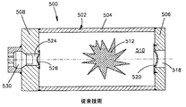
図5、6は膨張可能な車両乗員保護装置を膨張させる既知の膨張器500を示す。膨張器500は円筒状の部材504と、ディフューザー端キャップ506と、点火器端キャップ508とから形成される容器502を有する。室510が容器502内に画定される。ガス状の推進剤512は室510内に貯蔵される。ガス状の推進剤512は膨張流体を提供するために点火可能である。
5 and 6 show a known
流れ開口518はディフューザー端キャップ506を通って延びる。破裂可能なバーストディスク520は流れ開口518を閉じて、ガス状の推進剤512を室510内に維持する。
A
貫通穴524は点火器端キャップ508を通って延びる。貫通穴524は室510に隣接する端部において若干狭くなっている。破裂可能なバーストディスク526は室510に隣接して貫通穴524の開口を閉じる。
Through
点火器530は点火器端キャップ508に固定される。点火器530は室510内のガス状の推進剤512を点火するための燃焼生成物を提供するために作動することができる。
The
図6は作動状態の膨張器500を示す。点火器530が作動したとき、点火器530の点火により発生した燃焼生成物は点火器端キャップ508の貫通穴524を満たし、バーストディスク526を破裂させる。バーストディスク526が破裂すると、燃焼生成物は貫通穴524から室510内へ流入する。燃焼生成物が室510へ入ると、燃焼生成物は室510内のガス状の推進剤512の圧力よりも高い圧力となる。その結果、室510へ進入する際に、燃焼生成物は貫通穴524の中心軸線に関して半径方向外方へ扇状に拡がる。燃焼生成物の外方への扇状の拡がりは、図6に符号534で示すように、燃焼生成物のためのほぼ円錐状の流れパターンを発生させる。
FIG. 6 shows the
図5、6に示すように、膨張流体のための流れ開口518が点火器530とは反対側の容器502の端部に位置する場合、燃焼生成物の外方への扇状の拡がりは、点火器端キャップ508に隣接し、流れ開口518から離れて位置する燃焼区域を生じさせる。その結果、流れ開口518を覆っているバーストディスク520が破裂したとき、ガス状の推進剤512の一部は燃焼せずに流れ開口を通って室510から出ることがある。
As shown in FIGS. 5 and 6, when the flow opening 518 for the expansion fluid is located at the end of the
流れ開口518を通って室510から出る未燃焼のガス状推進剤512の量を最小化する補助を行うためには、高燃焼効率が望まれる。一層高い燃焼効率は流れ開口の一層近くに燃焼区域を位置させることにより達成できる。
High combustion efficiency is desired to assist in minimizing the amount of unburned
本発明は室を備えた容器を有する膨張器に関する。容器には出口開口が設けられる。出口開口は室に接続する。物質は室内に貯蔵される。物質は膨張流体を提供するために熱に応答できる。点火器は容器に関連し、物質を加熱するための燃焼生成物を提供するように作動できる。膨張器はまた点火器と室との間に位置するノズルを有する。通路は点火器からノズルを通って延びる。同通路は点火器からの燃焼生成物の流れを室内の物質を熱応答温度まで上昇させるため、当該室内に集中された流れとして供給するため収斂部分及び拡散部分を含む。 The present invention relates to an inflator having a container with a chamber. The container is provided with an outlet opening. The outlet opening connects to the chamber. The material is stored indoors. The material can respond to heat to provide an expanding fluid. The igniter is associated with the vessel and is operable to provide combustion products for heating the material. The inflator also has a nozzle located between the igniter and the chamber. A passage extends from the igniter through the nozzle. The passage includes a converging portion and a diffusion portion for supplying the flow of combustion products from the igniter as a concentrated flow in the chamber to raise the material in the chamber to a thermal response temperature.
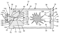
図1は本発明の第1の実施の形態に従って構成された膨張器10の断面図である。図1の膨張器10は軸方向で対向する第1及び第2の端部14、16をそれぞれ有する。
容器12は管状の本体部分22と、ディフューザー端キャップ26と、点火器端キャップ28とを有する。本体部分22は円筒状の内側及び外側の表面30、32をそれぞれ有する。内側及び外側の表面30、32の双方は軸線A上に中心を持つ。本体部分22はまた第1及び第2の開いた端部34、36をそれぞれ有する。第1の開いた端部34は容器12の第1の端部14の近傍に位置し、第2の開いた端部36は容器の第2の端部16の近傍に位置する。
FIG. 1 is a cross-sectional view of an
The
ディフューザー端キャップ26は円筒状の外側表面40と、第1及び第2の半径方向に延びる側表面42、44とを有する。円筒状の外側表面40は軸線A上に中心を持ち、本体部分22の外側表面32の直径にほぼ等しい直径を有する。ディフューザー端キャップ26の第1の側表面42は本体部分22の第2の開いた端部36に固定される。図1、2は本体部分22に溶接されたディフューザー端キャップ26を示す。
The
流れ通路48は第1の側表面42から第2の側表面44へディフューザー端キャップ26を通って軸方向に延びる。流れ通路48は軸線A上に中心を持つ。ディフューザー端キャップ26の円筒状の表面50は流れ通路48を画定する。流れ通路48はディフューザー端キャップ26の第1の側表面42上に第1の円形開口(符号なし)を形成し、ディフューザー端キャップ26の第2の側表面44上に第2の円形開口56を形成する。
A
バーストディスク60はディフューザー端キャップ26の流れ開口48を閉じる。バーストディスクはドーム状の中央部分62と、半径方向外方へ延びるフランジ部分64とを有する。バーストディスクのフランジ部分64はディフューザー端キャップ26の第1の側表面42に取り付けられる。図1、2は第1の側表面42に溶接されたバーストディスク60のフランジ部分64を示す。バーストディスク60のフランジ部分64がディフューザー端キャップ26の第1の側表面42に取り付けられたとき、バーストディスク60のドーム状の中央部分62は流れ通路48を閉じる。バーストディスク60のドーム状の中央部分62は所定の量の圧力差を受けたときに破裂するように設計される。
The
点火器端キャップ28は円筒状の外側表面70と、第1及び第2の半径方向に延びる側表面72、74とを有する。円筒状の外側表面70は軸線A上に中心を持ち、本体部分22の外側表面32の直径にほぼ等しい直径を有する。点火器端キャップ28の第2の側表面74は本体部分22の第1の開いた端部34に固定される。図1、2は本体部分22の第1の開いた端部34に溶接された点火器端キャップ28の第2の側表面74を示す。
The
膨張器10はまたノズル80を有する。図1、2は、点火器端キャップ28と一部品として形成され、一緒に固定された別個の部品として形成されないノズル80を示す。代わりに、ノズル80は点火器端キャップ28とは別個の部品として形成し、続いて点火器端キャップに固定することができる。
The
ノズル80は点火器端キャップ28の第2の側表面74から外方へ延びる。ノズル80は本体部分22の内側表面30の直径よりも小さな直径を有する円筒状の外側表面82を有する。図1に示すように、ノズル80は第1の開いた端部34から本体部分22内へ延びる。ノズル80は端表面84で終端する。端表面84は軸線Aに垂直な方向に延びる。
The
通路90は点火器端キャップ28及びノズル80を通って軸方向に延びる。中断のない表面92は点火器端キャップ28の第1の側表面72とノズル80の端表面84との間でその全体の軸方向長さに沿って通路90を画定する。中断のない表面92は傾斜部分(ベベル状部分)96と、円筒状部分98と、テーパ部分100と、湾曲部分102とを有する。表面92の傾斜部分96及び円筒状部分98は一緒になって通路90のほぼ円筒状の部分106を画定する。通路90の円筒状の部分106は点火器端キャップ28に関連する。表面92のテーパ部分100は通路90の収斂部分108を画定する。表面92の湾曲部分102は通路90の拡散部分110を画定する。通路の拡散部分は円形開口112を備えたノズル80の端表面84で終端する。通路90の収斂部分108及び拡散部分110はノズル80に関連する。通路90ののど部114は、通路90の収斂部分108と拡散部分110とが遭遇する位置に形成される。
The
バーストディスク116は通路90を閉じる。バーストディスク116は収斂部分108の近傍で通路90の円筒状部分106内に位置する。バーストディスク116は中断のない表面92の円筒状部分98に固定される。バーストディスク116は所定の量の圧力差を受けたときに破裂するように設計される。
The
室120は容器12内に位置する。流体122が室120内に貯蔵される。図1、2の膨張器10の室120内の流体122はガスの燃焼可能な混合物である。燃焼可能なガス混合物122は室120内に加圧下で貯蔵される。燃焼可能なガス混合物122の圧力はほぼ6,000psi(ポンド/平方インチ)である。燃焼可能なガス混合物122は好ましくは不活性ガス、水素及び酸素を含む。漏洩検出を補助するために燃焼可能なガス混合物に少量のヘリウムを添加することができる。所定の温度以上に加熱された場合、燃焼可能なガス混合物122が燃焼する。燃焼可能なガス混合物122の燃焼が不活性ガスを加熱する。加熱された不活性ガスは膨張流体となる。
燃焼可能なガス混合物122の代わりとして、室120内に貯蔵される流体は、所定の温度以上に加熱されたときに燃焼する燃焼可能な液体又は所定の温度以上に加熱されたときにガス化する液体とすることができる。例えばフレオンのような冷媒が所定の温度以上に加熱されたときにガス化する液体の例である。更なる代わりとして、流体は所定の温度以上に加熱されたときに分解するものでもよい。亜酸化窒素が所定の温度以上に加熱されたときに分解するガスの例である。
As an alternative to the
膨張器10はまた作動可能な点火器130を有する。点火器130は作動可能な部分132(図1)と支持部分134とを有する。作動可能な部分132は典型的には火工材料(図示せず)と、火工材料を点火するための抵抗ワイヤ(図示せず)とを有する。点火器130の支持部分134は軸線Aに関して作動可能な部分132よりも直径が大きく、対向するテーパ端表面140、142と、点火器を車両の安全装置(図示せず)の電子回路(図示せず)に接続するリード144とを有する。
The inflator 10 also has an
膨張器10はまた点火器端キャップ28に関して点火器130を支持するための支持部材150を有する。支持部材150はほぼ管状であり、切頭円錐形の表面152を含む。支持部材150は点火器端キャップに関して点火器130を固定するために点火器端キャップ28の第1の側表面72に取り付けられる。図1に示すように、点火器130が点火器端キャップ28に関して固定されたとき、点火器130の支持部分134のテーパ端表面140は表面92の傾斜部分96に当接し、支持部分のテーパ端表面142は支持部材150の切頭円錐形の表面152に当接する。また、点火器130が点火器端キャップ28に関して固定されたとき、点火器130の作動可能な部分132は、図1に示すように、通路90の円筒状部分106内に位置する。
The inflator 10 also has a
本発明の膨張器10は低濃度の燃焼可能なガス混合物122を有する膨張流体を提供するように作動できる。膨張器10を作動させるために、電気信号が点火器130に送られる。点火器130が電気信号を受け取ったとき、点火器130が作動する;すなわち、点火器の作動可能な部分132の火工材料が点火される。
The
点火器130の作動は燃焼生成物を発生させる。燃焼生成物は点火器130の作動可能な部分132の火工材料の点火により得られる。燃焼生成物は点火器130とバーストディスク116との間の通路90の円筒状部分106を満たし、燃焼生成物からの圧力がバーストディスクに作用する。点火器130の作動により得られた燃焼生成物はほぼ14,000psiの圧力に達することができる。バーストディスク116が室120からほぼ6,000psiの圧力を受けるので、燃焼生成物からの圧力はバーストディスク116を破裂させるのに十分である。
The operation of the
バーストディスク116が破裂したとき、燃焼生成物は通路90を通って室120の方へ流れ始める。燃焼生成物は通路90のより高い圧力の円筒状部分106からより低い圧力の室120の方へ流れる。より高い圧力の円筒状部分106内の燃焼生成物の圧力は典型的にはより低い圧力の室120の圧力の2倍よりも大きい。室120の方への流れ中、燃焼生成物は通路90の収斂部分108及び拡散部分110へ入る。燃焼生成物が通路90の収斂部分108を通って室120の方へ流れるとき、通路の流れ面積が減少する。その結果、燃焼生成物の圧力が増大し、燃焼生成物の流れが加速される。通路90ののど部114での燃焼生成物の流れがチョークを受けない場合、通路90を通る燃焼生成物の流れは亜音速となる。のど部114を通る燃焼生成物のマスフローがのど部の流れ面積に関して最大レベルに到達したときに、燃焼生成物の流れはのど部114においてチョークを受ける。従って、通路90ののど部114を通る燃焼生成物のマスフローが、例えば通路の円筒状部分106と室120との間の圧力差を増大させることにより、まだ増大することがある場合、のど部114を通る燃焼生成物の流れはチョークを受けていない。その結果、通路90を通る燃焼生成物の流れは亜音速を維持する。
When the
燃焼生成物が通路90ののど部114を通過した後、燃焼生成物は通路90の拡散部分110へ入る。燃焼生成物が通路90の拡散部分110を通って室120の方へ流れるとき、通路の流れ面積が増大する。通路90の拡散部分110を通っての燃焼生成物の流れ中、燃焼生成物の圧力は減少し、燃焼生成物の流れは加速される。燃焼生成物の圧力は通路90の拡散部分110において減少する。その結果、燃焼生成物が通路の拡散部分の端部における開口112に到達したときに、燃焼生成物は室120内の燃焼可能なガス混合物122の圧力にほぼ等しい圧力を有する。
After the combustion products pass through the
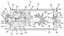
開口112において通路90を出る燃焼生成物が室120内の圧力に等しい圧力を有するので、燃焼生成物が室120へ入る際に、軸線Aに関して燃焼生成物の残留膨張は殆ど又は全く生じない。より詳しくは、室120へ入るとき、燃焼生成物の流れは軸線Aに平行な方向を向いており、軸線Aに関する半径方向の流れは最少化される。その結果、通路90の拡散部分110からの燃焼生成物の流れは集中されると言える。図2は燃焼生成物のこの集中された流れを符号160にて示す。室120内への燃焼生成物の集中された流れは、図5、6の膨張器500を参照して説明したような、燃焼生成物の半径方向の膨張が生じるような膨張器に比べて、室120のより長い軸方向の距離にわたってより速い速度で運行する燃焼生成物を生じさせる。
Because the combustion product exiting the
燃焼生成物の集中された流れがより長い軸方向距離を運行するので、燃焼可能なガス混合物122を点火する燃焼生成物から由来する燃焼区域はディフューザー端キャップ26の流れ通路48の一層近くに位置することになる。一般に、燃焼区域がディフューザー端キャップ26の流れ通路48の近くに位置するほど、燃焼区域を通過して室120を出る前に燃焼される燃焼可能なガス混合物122の量が一層多くなる。その結果、膨張器10により提供される膨張流体は一層低い濃度の燃焼可能なガス混合物122を有する。
Because the concentrated flow of combustion products travels a longer axial distance, the combustion zone originating from the combustion products that ignite the
図2は、点火器130の作動のすぐ後及びバーストディスク116、60の破裂後の、膨張器10を示す。図2の矢印162は流れ通路48を通って膨張器10の室120を出る低濃度の燃焼可能なガス混合物122を有する膨張流体を示す。
FIG. 2 shows the inflator 10 immediately after actuation of the
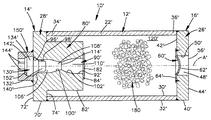
図3は本発明の第2の実施の形態に従って構成された膨張器10´の断面図である。図1、2に示したものと同一又は類似の図3の膨張器10´の素子は同じ符号で示し、その後に「´」を付加する。更に、図3の膨張器10´と図1、2の膨張器10との間の差異のみを以下に説明する。
FIG. 3 is a cross-sectional view of an inflator 10 'constructed in accordance with the second embodiment of the present invention. Elements of the inflator 10 'of FIG. 3 that are the same or similar to those shown in FIGS. Furthermore, only the differences between the inflator 10 'of FIG. 3 and the
図3の膨張器10´は熱を加えたときに点火できる固形の推進剤材料180を含む。図1に示す固形の推進剤材料180は小さなパレットの形をしている。膨張器10´の容器12´の室120´は固形の推進剤材料180で充填される。容器12´の室120´が加圧されていないので、図1のバーストディスク116と同様のバーストディスクを通路90´内に設ける必要はない。代わりに、箔材料182を通路90´の開口の上方に延在させることができ、ノズル80´の端表面84´に接着することができる。箔材料182は、固形の推進剤材料180が通路90´に入るのを阻止する。
The expander 10 'of FIG. 3 includes a
更に、図3の膨張器10´においては、点火器130´及び通路90´は通路の拡散部分110´内に燃焼生成物の超音速流れを提供するように設計される。のど部114´において燃焼生成物の流れがチョークを受けたときに、通路90´の拡散部分110´内で燃焼生成物の超音速流れが発生する。のど部114´を通る燃焼生成物のマスフローが最大レベルに達したときに、のど部114´での燃焼生成物の流れはチョークを受ける。のど部114´の与えられた流れ面積に対して、のど部114´を通る燃焼生成物のマスフローが、通路90´の円筒状部分106´と室120´との間の圧力差の増大に応答して、増大しない場合は、のど部114´を通る燃焼生成物のマスフローは最大レベルに達する。点火器130´の作動により生じる燃焼生成物及び室120´内の圧力に関するデータが与えられれば、ノズル分野の当業者なら、チョークを生じさせるための通路90´ののど部114´の適当な流れ面積を決定できる。
Further, in the expander 10 'of FIG. 3, the igniter 130' and the passage 90 'are designed to provide a supersonic flow of combustion products within the passage diffusion portion 110'. When the combustion product flow is choked at the throat 114 ', a supersonic flow of combustion product is generated in the diffusion portion 110' of the passage 90 '. When the mass flow of combustion products through the throat 114 'reaches a maximum level, the flow of combustion products at the throat 114' is choked. For a given flow area of the
のど部114´での燃焼生成物の流れがチョークを受けたとき、のど部114´での燃焼生成物の流速は音速即ちマッハ1に等しくなる。超音速流れの区域は通路90´の拡散部分110´内ののど部114´のすぐ下流側に形成される。超音速流れの区域は普通の衝撃波か又はショックパターンのいずれかの発生により終端する。超音速流れの区域は通路90´の拡散部分110´内で終端することができ、または、室120´内の通路90´の拡散部分110´の下流で終端することができる。超音速流れの区域が終端する位置は、通路90´の円筒状部分106´内の燃焼生成物と室120´内の圧力との間の圧力差の関数である。超音速流れの区域が終端する位置の制御はノズルの分野の当業者にとって周知である。
When the flow of combustion products at the
超音速流れの区域が通路90´の拡散部分110´内で終端すると、普通の衝撃波が発生する。普通の衝撃波は亜音速への燃焼生成物の流れのほぼ瞬時の減速を生じさせる。普通の衝撃波の後、燃焼流体の亜音速流れが拡散部分110´の残りの部分にわたって減速し、図2を参照して説明したように、燃焼生成物の集中された流れとして通路90´から出る。 When the supersonic flow zone terminates in the diffused portion 110 'of the passage 90', a normal shock wave is generated. Ordinary shock waves cause an almost instantaneous deceleration of the combustion product flow to subsonic speed. After a normal shock wave, the subsonic flow of combustion fluid decelerates over the remainder of the diffusion portion 110 'and exits the passage 90' as a concentrated flow of combustion products, as described with reference to FIG. .
超音速流れの区域が室120´内の通路90´の拡散部分110´の下流で終端する場合、ショック及び反射の複雑なパターンが通路90´を出る燃焼生成物の集中された流れ内に形成される。ショック及び反射の複雑なパターンは典型的には亜音速流れと超音速流れとの混合物を含む。図4は通路90´を出る燃焼生成物の集中された流れ内に位置するショックダイアモンドとしてのショック及び反射の複雑なパターンを概略的に示す。 When the supersonic flow zone terminates downstream of the diffused portion 110 'of the passage 90' in the chamber 120 ', a complex pattern of shock and reflection forms in the concentrated flow of combustion products exiting the passage 90'. Is done. The complex pattern of shock and reflection typically includes a mixture of subsonic and supersonic flows. FIG. 4 schematically illustrates a complex pattern of shock and reflection as a shock diamond located in a concentrated flow of combustion products exiting the passage 90 '.
ノズル80´内の通路90´の拡散部分110´を通る燃焼生成物の超音速流れを提供することにより、室120´内へと燃焼生成物が運行する距離が増大する。その結果、固形の推進剤材料180の点火により形成される燃焼区域はディフューザー端キャップ26´の流れ通路48´のより近くに位置する。更に、燃焼生成物のより速い速度が固形の推進剤材料180の表面への一層大きな熱伝達率を産み出し、固形の推進剤材料の点火を改善する。超音速流れの終端に由来する普通の衝撃波又はショックパターンは固形の推進剤材料の燃焼表面積を増大させるように固形の推進剤材料180の一部を粉砕するために使用することができる。
By providing a supersonic flow of combustion products through the diffusing portion 110 'of the passage 90' in the nozzle 80 ', the distance traveled by the combustion products into the chamber 120' is increased. As a result, the combustion zone formed by ignition of the
図4は点火器130´の作動のすぐ後で、箔材料182及びバーストディスク60´の破裂の後の、膨張器10´を示す。固形の推進剤材料180の燃焼により形成された膨張流体は流れ通路48´を通って膨張器10´の室120´から出る。
FIG. 4 shows the inflator 10 ′ immediately after actuation of the
本発明の上述の説明から、当業者なら、改善、変更及び修正を理解できよう。例えば、図1、2の膨張器10のノズル80の収斂部分108、拡散部分110及びのど部114も、燃焼生成物の超音速流れを可能にするように設計できる。また、図3、4の容器12´の室120´は貯蔵されたガスで加圧することができる。室120´が貯蔵されたガスで加圧される場合、図1のバーストディスク116と同様のバーストディスクを通路90´内で使用して、室120´からの圧力の損失を阻止することができる。
From the above description of the invention, those skilled in the art will perceive improvements, changes and modifications. For example, the converging
10、10´ 膨張器
12、12´ 容器
26、26´ ディフューザー端キャップ
28 点火器端キャップ
48、48´ 流れ通路
60、60´ バーストディスク
80、80´ ノズル
90、90´ 通路
108 収斂部分
110、110´ 拡散部分
114、114´ のど部
116 バーストディスク
120、120´ 室
122 流体
130、130´ 点火器
160 集中された流れ
180 固形の推進剤材料
10, 10 '
Claims (13)
室(120)を有する容器(12)であって、同容器(12)内に設けられ、上記室(120)に接続する出口開口(48)を備えた容器(12)と;
上記室(120)内に貯蔵され、膨張流体を提供するための熱に応答する物質(122,180)と;
上記容器(12)に組み合わされ、上記物質(122,180)を加熱するための燃焼生成物を提供するように作動できる点火器(130)と;
上記点火器(130)と上記室(120)との間に位置するノズル(80)であって、当該点火器(130)から上記ノズルを通って延びる通路(90)を有し、同通路(90)が該点火器(130)からの燃焼生成物の流れを上記室(120)内の上記物質(122,180)を熱応答温度まで上昇させるため、当該室(120)内に集中された流れとして供給するため収斂部分(108)及び拡散部分(110)を含むようなノズルと;
を有することを特徴とする膨張器。 In the inflator,
A container (12) having a chamber (120), provided in the container (12), with an outlet opening (48) connected to said chamber (120) container (12);
A material (122, 180) that is stored in the chamber (120) and is responsive to heat to provide an expansion fluid;
An igniter (130) combined with the container (12) and operable to provide a combustion product for heating the material (122, 180) ;
A nozzle (80) located between the igniter (130) and said chamber (120) has a passageway (90) extending the igniter from (130) through said nozzle, said passage ( 90) is concentrated in the chamber (120) to raise the flow of combustion products from the igniter (130) to the material (122, 180) in the chamber (120) to a thermal response temperature . A nozzle that includes a converging portion (108) and a diffusing portion (110) for delivery as a stream ;
An inflator characterized by comprising:
Applications Claiming Priority (1)
| Application Number | Priority Date | Filing Date | Title |
|---|---|---|---|
| US11/055,360 US7703395B2 (en) | 2005-02-10 | 2005-02-10 | Inflator having an ignition nozzle |
Publications (2)
| Publication Number | Publication Date |
|---|---|
| JP2006219125A JP2006219125A (en) | 2006-08-24 |
| JP4248552B2 true JP4248552B2 (en) | 2009-04-02 |
Family
ID=36776382
Family Applications (1)
| Application Number | Title | Priority Date | Filing Date |
|---|---|---|---|
| JP2006033257A Expired - Fee Related JP4248552B2 (en) | 2005-02-10 | 2006-02-10 | Inflator |
Country Status (3)
| Country | Link |
|---|---|
| US (1) | US7703395B2 (en) |
| JP (1) | JP4248552B2 (en) |
| DE (1) | DE102006006036A1 (en) |
Families Citing this family (12)
| Publication number | Priority date | Publication date | Assignee | Title |
|---|---|---|---|---|
| DE102008022755B4 (en) * | 2008-05-08 | 2015-05-13 | Trw Airbag Systems Gmbh | inflator |
| DE102008027048A1 (en) * | 2008-06-06 | 2009-12-10 | Trw Airbag Systems Gmbh | Gas generator for generating gas, e.g. for airbag, has first igniter at one end of chamber to ignite gas or mixture in chamber when generator is activated |
| US7883108B2 (en) * | 2008-09-04 | 2011-02-08 | Autoliv Asp, Inc. | Inflator for an airbag |
| CN103465864B (en) * | 2008-09-30 | 2017-03-15 | Trw空气气袋系统股份有限公司 | Gas generator, its manufacture method and the module with gas generator |
| CN102292244B (en) * | 2009-01-22 | 2016-04-13 | 奥托里夫Asp股份有限公司 | Gas generator for airbag device |
| JP5136527B2 (en) * | 2009-08-31 | 2013-02-06 | 豊田合成株式会社 | Actuator |
| CN102095800A (en) * | 2011-02-17 | 2011-06-15 | 西安电子科技大学 | System for testing ultrasonic dynamic burning rate of solid propellant |
| JP5965334B2 (en) * | 2013-02-18 | 2016-08-03 | 株式会社ダイセル | Gas generator |
| DE202016001333U1 (en) * | 2016-02-12 | 2017-05-17 | Trw Airbag Systems Gmbh | Hybrid gas generator, gas bag module and vehicle safety system |
| US11673528B2 (en) | 2017-01-11 | 2023-06-13 | Automotive Technologies International, Inc. | Airbag inflators including aspirators |
| US11155235B2 (en) | 2017-01-11 | 2021-10-26 | Automotive Technologies International, Inc. | Airbags including inflator assemblies |
| JP6695365B2 (en) * | 2018-01-25 | 2020-05-20 | 本田技研工業株式会社 | High pressure tank structure |
Family Cites Families (20)
| Publication number | Priority date | Publication date | Assignee | Title |
|---|---|---|---|---|
| US3632133A (en) * | 1969-02-25 | 1972-01-04 | Eaton Yale & Towne | Vehicle safety apparatus including an inflatable confinement |
| US3630150A (en) * | 1969-10-27 | 1971-12-28 | Singer Co | Actuating mechanism |
| US3630151A (en) * | 1969-10-27 | 1971-12-28 | Singer Co | Manually actuated fluidic igniter |
| US3807755A (en) * | 1972-11-13 | 1974-04-30 | Gen Motors Corp | Occupant restraint system |
| US4033267A (en) * | 1976-10-01 | 1977-07-05 | The United States Of America As Represented By The Secretary Of The Navy | Flueric cartridge initiator |
| FR2569686B1 (en) * | 1984-09-05 | 1986-11-21 | Poudres & Explosifs Ste Nale | ULTRA-FAST GAS GENERATOR WITH ENHANCED SECURITY |
| US5443286A (en) * | 1992-10-09 | 1995-08-22 | Morton International, Inc. | Gas generator for vehicle occupant restraint system |
| US5388859A (en) * | 1993-11-09 | 1995-02-14 | Trw Inc. | Isolation member for air bag inflator |
| US5423570A (en) * | 1994-05-09 | 1995-06-13 | Morton International, Inc. | Hybrid inflator with tortuous delivery passage |
| DE19507208A1 (en) * | 1995-03-02 | 1996-09-05 | Dynamit Nobel Ag | Gas generator, in particular for an airbag, with a loading container and a flame guide tube |
| US5820160A (en) * | 1996-03-01 | 1998-10-13 | Autoliv Asp, Inc. | Airbag inflator with venturi effect cooling and gas supplement |
| US5768885A (en) * | 1996-12-03 | 1998-06-23 | Autoliv Asp, Inc. | Regenerative piston liquid propellant rocket motor |
| US6237590B1 (en) * | 1997-09-18 | 2001-05-29 | Delsys Pharmaceutical Corporation | Dry powder delivery system apparatus |
| US6019389A (en) * | 1998-03-31 | 2000-02-01 | Trw Vehicle Safety Systems Inc. | Air bag inflator |
| US6142516A (en) * | 1998-09-10 | 2000-11-07 | Trw Inc. | Air bag inflator assembly |
| US6237950B1 (en) | 1999-07-26 | 2001-05-29 | Trw Vehicle Safety Systems Inc. | Staged air bag inflator |
| WO2003042010A1 (en) * | 2001-11-15 | 2003-05-22 | Nippon Kayaku Kabushiki-Kaisha | Gas generator |
| US6629703B2 (en) * | 2001-12-14 | 2003-10-07 | Breed Automotive Technology, Inc. | Opening device for a cold gas inflator |
| US6846014B2 (en) * | 2002-03-18 | 2005-01-25 | Autoliv Asp, Inc. | Inflatable surface including a plurality of nozzles |
| DE20319564U1 (en) | 2003-12-17 | 2004-04-15 | Trw Airbag Systems Gmbh | inflator |
-
2005
- 2005-02-10 US US11/055,360 patent/US7703395B2/en not_active Expired - Fee Related
-
2006
- 2006-02-09 DE DE102006006036A patent/DE102006006036A1/en not_active Withdrawn
- 2006-02-10 JP JP2006033257A patent/JP4248552B2/en not_active Expired - Fee Related
Also Published As
| Publication number | Publication date |
|---|---|
| JP2006219125A (en) | 2006-08-24 |
| US20060174794A1 (en) | 2006-08-10 |
| DE102006006036A1 (en) | 2006-08-24 |
| US7703395B2 (en) | 2010-04-27 |
Similar Documents
| Publication | Publication Date | Title |
|---|---|---|
| JP3089358B2 (en) | Double pyrotechnic mixed gas filling device | |
| US8052169B2 (en) | Gas generator for inflating a gas bag of a vehicle occupant restraint system and method of inflating a gas bag | |
| KR0167792B1 (en) | Gas bag inflator | |
| KR0183410B1 (en) | Hybrid Inflator for Vehicle Passenger Restraint System | |
| US5803493A (en) | Hybrid blowdown inflator with reduced pressure buildup | |
| JP2609428B2 (en) | Inflator | |
| JP4248552B2 (en) | Inflator | |
| US6382668B1 (en) | Air bag inflator | |
| KR0179997B1 (en) | Apparatus for inflating an inflatable vehicle occupant restraint | |
| US6206414B1 (en) | Air bag inflator including plural burst disks | |
| US5536040A (en) | Inflator for side impact air bag | |
| JPH05278554A (en) | Vehicle occupant restraint | |
| JPH0710655B2 (en) | Vehicle occupant restraint inflator | |
| JPH06508320A (en) | Hybrid airbag inflator | |
| JP2764020B2 (en) | Device for inflating an airbag | |
| WO2001042047A9 (en) | Vehicle inflator | |
| US6010152A (en) | Air bag inflator | |
| JPH08230607A (en) | Expansion devcie for air bag and manufacture of said devcie | |
| JP2650846B2 (en) | Device for expanding vehicle occupant restraint | |
| US6786507B2 (en) | Hybrid gas generator | |
| US6273462B1 (en) | Air bag inflator | |
| JPH07502470A (en) | hybrid inflator | |
| US5584504A (en) | Inflator assembly | |
| JPH07195996A (en) | Device and method for inflating inflatable vehicle passenger restraint | |
| KR20010023550A (en) | Gas bag arrangement with a gas guide housing comprising partial discharge areas |
Legal Events
| Date | Code | Title | Description |
|---|---|---|---|
| A131 | Notification of reasons for refusal |
Free format text: JAPANESE INTERMEDIATE CODE: A131 Effective date: 20080515 |
|
| A601 | Written request for extension of time |
Free format text: JAPANESE INTERMEDIATE CODE: A601 Effective date: 20080814 |
|
| A602 | Written permission of extension of time |
Free format text: JAPANESE INTERMEDIATE CODE: A602 Effective date: 20080819 |
|
| A521 | Request for written amendment filed |
Free format text: JAPANESE INTERMEDIATE CODE: A523 Effective date: 20081015 |
|
| TRDD | Decision of grant or rejection written | ||
| A01 | Written decision to grant a patent or to grant a registration (utility model) |
Free format text: JAPANESE INTERMEDIATE CODE: A01 Effective date: 20081225 |
|
| A01 | Written decision to grant a patent or to grant a registration (utility model) |
Free format text: JAPANESE INTERMEDIATE CODE: A01 |
|
| A61 | First payment of annual fees (during grant procedure) |
Free format text: JAPANESE INTERMEDIATE CODE: A61 Effective date: 20090113 |
|
| FPAY | Renewal fee payment (event date is renewal date of database) |
Free format text: PAYMENT UNTIL: 20120123 Year of fee payment: 3 |
|
| R150 | Certificate of patent or registration of utility model |
Ref document number: 4248552 Country of ref document: JP Free format text: JAPANESE INTERMEDIATE CODE: R150 Free format text: JAPANESE INTERMEDIATE CODE: R150 |
|
| FPAY | Renewal fee payment (event date is renewal date of database) |
Free format text: PAYMENT UNTIL: 20130123 Year of fee payment: 4 |
|
| R250 | Receipt of annual fees |
Free format text: JAPANESE INTERMEDIATE CODE: R250 |
|
| R250 | Receipt of annual fees |
Free format text: JAPANESE INTERMEDIATE CODE: R250 |
|
| R250 | Receipt of annual fees |
Free format text: JAPANESE INTERMEDIATE CODE: R250 |
|
| R250 | Receipt of annual fees |
Free format text: JAPANESE INTERMEDIATE CODE: R250 |
|
| R250 | Receipt of annual fees |
Free format text: JAPANESE INTERMEDIATE CODE: R250 |
|
| R250 | Receipt of annual fees |
Free format text: JAPANESE INTERMEDIATE CODE: R250 |
|
| R250 | Receipt of annual fees |
Free format text: JAPANESE INTERMEDIATE CODE: R250 |
|
| R250 | Receipt of annual fees |
Free format text: JAPANESE INTERMEDIATE CODE: R250 |
|
| LAPS | Cancellation because of no payment of annual fees |