JP4248317B2 - transponder - Google Patents
transponder Download PDFInfo
- Publication number
- JP4248317B2 JP4248317B2 JP2003176195A JP2003176195A JP4248317B2 JP 4248317 B2 JP4248317 B2 JP 4248317B2 JP 2003176195 A JP2003176195 A JP 2003176195A JP 2003176195 A JP2003176195 A JP 2003176195A JP 4248317 B2 JP4248317 B2 JP 4248317B2
- Authority
- JP
- Japan
- Prior art keywords
- ground
- signal
- predetermined
- train
- vehicle
- Prior art date
- Legal status (The legal status is an assumption and is not a legal conclusion. Google has not performed a legal analysis and makes no representation as to the accuracy of the status listed.)
- Expired - Fee Related
Links
- 238000012795 verification Methods 0.000 claims description 10
- 230000005856 abnormality Effects 0.000 claims description 5
- 230000005540 biological transmission Effects 0.000 claims description 5
- 238000001514 detection method Methods 0.000 description 6
- 238000000034 method Methods 0.000 description 6
- 238000010586 diagram Methods 0.000 description 5
- 230000007423 decrease Effects 0.000 description 1
- 238000004870 electrical engineering Methods 0.000 description 1
- 230000005611 electricity Effects 0.000 description 1
- 230000007246 mechanism Effects 0.000 description 1
Images
Landscapes
- Train Traffic Observation, Control, And Security (AREA)
Description
【0001】
【発明の属する技術分野】
本発明は列車制御に用いられるトランスポンダに係り、特に、ホームドア装置のように、列車を所定の定点に停車させるときに好適なトランスポンダに関する。
【0002】
【従来の技術】
従来から列車(車両)のATS等の制御用としてトランスポンダが使用されている(非特許文献1参照)。この列車制御用のトランスポンダは、列車の下部に車上子(車上アンテナ)を設けるとともに、その列車の走行する軌道(レール)の近傍に地上子(地上アンテナ)が設けられ、その地上子は、中継器や符号処理器等からなる地上設備に接続されている。そして、列車の移動により地上子上に車上子が所定距離の範囲内に位置したときに、地上から車上(列車)へ、又は車上から地上へ、あるいは双方向に列車位置情報や列車識別情報等の所定の情報の伝送が行われるように構成されている。
【0003】
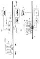
図4(a),(b)は、上記トランスポンダをホームドア装置に適用した従来例を示している。ホームHには、後述するホームドア制御装置で開閉制御されるホームドアD,Dが設けられているとともに、そのホームHの列車イの走行する軌道Tの軌間の所定位置には、トランスポンダの地上子aが設けられている。そして、その軌道Tを走行する列車イの下部には、トランスポンダの車上子bが搭載されている。これら地上子a及び車上子bは、地上子a上に列車イの車上子bが正しく対向して位置して停車した際、列車イのドアとホームドアD,Dとが対向するように決められている。
【0004】
図4(a),(b)中、1は、地上に設けられた地上装置であり、2は、ホームドア制御装置である。地上装置1は、モデムを含む中継器RPとCPUを中心に形成された符号処理器ECとが含まれている。そして、地上装置1は、地上子aが図4(b)に示されるように、列車イがホームHの所定位置に停車し、地上子a上に車上子bが位置したときに、その車上子bから送信される列車イの識別情報を含む所定の車上情報を受信し、その受信した車上情報を基に地上装置1からホームドア制御装置2に所定の出力信号が出力されるように構成されている。ホームドア制御装置2は、地上装置1から所定の信号を受信することにより、ホームドアD,Dに対して開くように駆動制御信号が出力される。したがって、ホームドアD,Dは、ホームドア制御装置2からの駆動制御信号により開かれる。なお、本発明の説明に直接関係しないので詳述しないが、列車イのドアも所定位置(地上子a及び車上子bが正常に対向した位置)に停車したことを条件に開かれ、また、ホームドアD,Dが閉じられたことを条件に列車イのドアも閉じられて出発が許可されるように構成されている。
【0005】
地上子a及びモデムを含む中継器RPは、本発明の実施の形態の項で詳述するが、中継器RPから定期的(間欠的)に車上子bから送信されてくる信号と同種の照査信号(例えば、搬送中心周波数3.0MHzの信号)が地上子aに送信され、その送信された照査信号が地上子aから中継器RPに正しく受信されているか否かにより地上子aの状態がチェックされるように構成されている。また、地上子a上に車上子bが位置したときに、乗客の乗降により列車イが揺動し、地上子aの受信レベルに変動が生じても、地上子a上に車上子bが位置したことを検知する検知信号、いわゆるCD検知信号を安定して受信できるようにするためにヒステリシス処理が行われるように構成されている。
【0006】
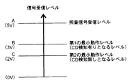
このヒステリシス処理を本発明の実施の形態の説明の項で用いる図2を用いてさらに説明すると、ここでは説明を簡単にするために、地上子aのチェック用の照査信号の受信レベルAが5Vとされ、また、第1の最小動作レベルBとして3Vとされ、そして、CD検知無しとなる第2の最小動作レベルCが2Vとされている。
【0007】
このように、各レベルA,B,Cが決められている状態において、地上子aのチェックは、地上子aから中継器RP(モデム)に定期的に5Vの受信信号が入力されて行われる。そして、地上子aが正常と判定されている間、地上子a上に車上子bが位置し、中継器RPが3V以上の受信信号を受信したときに、最小動作レベルを3Vから2Vに設定変更し、2V以上の受信信号を基に車上からの情報を処理するように構成されている。このような、レベルB(3V)からレベルC(2V)へのヒステリシス処理は、アナログ的な処理により行われる。
【0008】
【非特許文献1】
平成9年5月15日四版(社)日本鉄道電気技術協会発行「鉄道技術者のための電気概論」P.35〜40
【0009】
【発明が解決しようとする課題】
しかしながら、上記構成のヒステリシス処理を行うトランスポンダにおいて、地上子上に車上子が所定の位置よりも外れて位置した場合に列車(車上子)が移動したと誤認識するおそれがあった。
【0010】
上記図4(a),(b)及び図2を用いてさらに具体的に説明すると、列車イが所定位置から少し外れた位置に停車した場合、そのときのモデムMの受信レベルが2.3Vであったとする。この2.3Vは、図2の第1の最小動作レベルの3Vに達しないので、中継器RP側(地上側)では、地上子a上に車上子bが位置していないCD検知なしと判定される。つまり、地上側では、列車イは、まだ所定位置に達していないと判定される。
【0011】
この状態において、照査信号の5VがモデムMに受信されるとヒステリシス処理によりCD検知無しとなる2V(図2のC参照)を越える2.3Vの信号を受信しているので、地上子a上に車上子bが位置しているCD検知ありとなる。このとき、列車イの揺動により地上子a及び車上子b間の距離が大きくなって受信信号が2.3VからCD検知なしとなる2V以下の1.8Vに下がる。このため、中継器RP側(地上側)では、地上子a上から車上子bが移動したと認識し、すなわち、列車イが移動したと誤認することになる。
【0012】
そこで、本発明は、上述のような誤認を効果的に除去できるようにしたトランスポンダを提供することを目的とする。
【0013】
【課題を解決するための手段】
本発明に係るトランスポンダは、上記目的を達成するために、請求項1に記載の発明は、地上子から得られる信号の受信レベルが所定の第1の最小動作レベル以上のとき、前記信号が前記地上子の正常/異常をチェックする照査信号か列車に搭載された車上子からの送信信号かを判定し、前記照査信号でないと判定したとき前記地上子上に前記車上子が位置したと判定する判定手段と、前記地上子上に前記車上子が位置したと判定されたときに、前記所定の第1の最小動作レベルよりも低い所定の第2の最小動作レベルを設定する設定手段と、前記所定の第2の最小動作レベルを越える受信信号に基づいて前記車上子から送信されてくる所定の車上情報を取込む取込手段と、を有することを特徴としている。
本発明の請求項2に記載のトランスポンダは、地上子は、ホームドア装置に設けられるものであることを特徴としている。
【0014】
【発明の実施の形態】
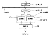
以下、本発明の実施の形態を図面に基づいて説明する。図1は、上記図4(a),(b)に示されるホームドア装置に適用した一実施の形態に係るトランスポンダの概略構成図である。
【0015】
図1中、aは、列車(車両)イの走行する軌道Tの軌間の所定位置に設置された地上子(地上アンテナ)であり、bは、図1では省略されている列車イ(図4(a),(b)参照)下部に取付けられて搭載されている車上子(車上アンテナ)である。これら地上子a及び車上子bは、その地上子a上に列車イの車上子bが所定どおり対応してその列車イが停車した際、列車イのドアとホームドアD,Dとが対向するように決められている(図4(b)参照)。
【0016】
図1中、RPは中継器であって、変調器10及び復調器11からなるモデムMと、CPUを中心に形成され、中継器RPを統括的に制御する論理部12とを含んで構成されている。この論理部12は、図示しないモデム及び整合・入出力部を介して図4(a),(b)に示されるCPUを含んで形成される符号処理器1へ接続されている。なお、この図1に示される中継器RPは、本発明の説明に特に必要がないので、地上子aから車上子bに向けての情報、すなわち、地上から車上(列車イ)に向けての情報伝送機構は省略されている。
【0017】
変調器10は、論理部12からの指令に基づいて定期的に地上子aに所定の照査信号を出力できるように構成されている。この照査信号は、車上子bから地上子aに向けて送信される信号と同種の信号で、例えば、搬送中心周波数が3.0MHzの照査信号が使用される。
【0018】
復調器11は、変調器10から定期的に地上子aに送信された照査信号を受信するとともに、車上子bから送信された所定の信号を地上子aを介して受信し、それら受信信号を復調処理することができるように構成されている。復調器11に受信される2つの受信信号のうち、照査信号は、地上子aを介して直接受信されるので、車上子bを介して受信される受信レベルよりも高い値で受信される(後述の図2のA参照)。また、車上子bから送信される信号中には、その車上子bが搭載されている列車イの識別情報を含む所定の車上情報が含まれている。
【0019】
図2は、復調器11(モデムM)の受信した信号レベルの説明図であり、Aは、照査信号の受信レベルの5Vを表わし、Bは、本発明の第1の最小動作レベルの3Vを表わし、そして、Cは、本発明の第2の最小動作レベルの2Vを表わしている。なお、ここで示される5V,3V,2Vは、説明を容易にするための一例である。
【0020】
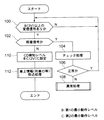
以下、図3のフローチャートを用いて制御動作について説明する。今、復調器11(モデムM)が第1の最小動作レベルB(3V)以上の信号を受信したとする(ステップ100肯定。以下、ステップを「S」とする。)。この第1の最小動作レベルB以上の信号を受信したとき、中継器RPがチェックモード時であれば、すなわち、変調器10から地上子aを介して復調器11に対して定期的に出力される照査信号の出力時であれば、その受信された信号は照査信号であるので(S102肯定)、この場合は、論理部12の制御の下、所定のチェック処理が行われる(S104)。そして、このチェック処理において、地上子aに故障が発生したと判定されたときは(S106否定)、その異常発生状態は、論理部12を介して地上装置1(図4(a),(b)参照)に送信され所定の異常処理が行われる(S108)。
【0021】
上述のチェック処理により地上子aが正常と判定されている間において、復調器11(モデムM)が第1の最小動作レベルB(3V)以上の信号を受信し、かつ、その受信時が上述のチェック時でないとき(S102否定)、論理部12は、地上子a上に車上子bが位置したと判定し、復調器11の最小動作レベルを第1の最小動作レベルB(3V)から第2の最小動作レベルC(2V)に設定する(S110)。そして、論理部12は、その第2の最小動作レベルC以上を受信している受信信号に基づいて列車イの識別情報を含む車上情報の取込処理が行われる(S112)。
【0022】
上述のように、地上子aのチェック時でないときに、一度、第1の最小動作レベルB以上の受信信号が受信されると、デジタル処理により最小動作レベルが第2の最小レベルCに引き下げられ、その第2の最小レベル以上の受信信号に基づいて車上情報の取込が行われる。このため、列車イの揺動に伴う受信レベルの変動があっても、発明の課題の項で説明したような列車が移動(出発)してしまったというような誤認を未然に防止することができる。
【0023】
なお、図3のフローチャートでは省略されているが、中継器RPを介して所定の列車(図示の例では列車イ)が所定の位置(定点)に停車したと判定されたときは、符号処理器(CPU)ECからホームドア制御装置2に所定の列車停車信号が送信される。ホームドア制御装置2は、符号処理器ECから所定の列車停車信号を受信すると、ホームドアD,Dに対してドアを開くための駆動信号が出力される。
【0024】
【発明の効果】
本発明の請求項1に記載のトランスポンダは、地上子から得られる信号の受信レベルが所定の第1の最小動作レベル以上のとき、前記信号が前記地上子の正常/異常をチェックする照査信号か列車に搭載された車上子からの送信信号かを判定し、前記照査信号でないと判定したとき前記地上子上に前記車上子が位置したと判定する判定手段と、前記地上子上に前記車上子が位置したと判定されたときに、前記所定の第1の最小動作レベルよりも低い所定の第2の最小動作レベルを設定する設定手段と、前記所定の第2の最小動作レベルを越える受信信号に基づいて前記車上子から送信されてくる所定の車上情報を取込む取込手段とを有するので、列車の揺動等に伴って出力信号に変動があっても、安定して車上情報を取込むことが可能となる。
本発明の請求項2に記載のトランスポンダは、地上子は、ホームドア装置に設けられるので、ホームドアの制御を効率よく行うことができる。
【図面の簡単な説明】
【図1】本発明の一実施の形態に係るトランスポンダの概略構成図である。
【図2】受信信号及び最小動作レベルの説明図である。
【図3】制御動作を示すフローチャートである。
【図4】トランスポンダを適用したホームドア装置の概略構成図である。
【符号の説明】
a 地上子
b 車上子
RP 中継器
M モデム
10 変調器
11 復調器
12 論理部
T 軌道
イ 列車
1 地上装置
2 ホームドア制御装置
H ホーム
D ドア[0001]
BACKGROUND OF THE INVENTION
The present invention relates to a transponder used for train control, and more particularly to a transponder suitable for stopping a train at a predetermined fixed point, such as a platform door device.
[0002]
[Prior art]
Conventionally, a transponder has been used for controlling an ATS or the like of a train (vehicle) (see Non-Patent Document 1). This transponder for train control is provided with a vehicle element (vehicle antenna) at the lower part of the train, and a ground element (ground antenna) is provided in the vicinity of the track (rail) that the train travels. It is connected to ground equipment consisting of repeaters and code processors. Then, when the vehicle upper element is positioned within a predetermined distance on the ground element due to the movement of the train, the train position information and the train are either from the ground to the vehicle (train), from the vehicle to the ground, or both directions. Transmission of predetermined information such as identification information is performed.
[0003]
4A and 4B show a conventional example in which the transponder is applied to a home door device. The home H is provided with home doors D and D that are controlled to be opened and closed by a home door control device, which will be described later, and at a predetermined position between the trajectories of the track T on which the train H of the home H travels, A child a is provided. And, the upper part b of the transponder is mounted on the lower part of the train A traveling on the track T. These ground child a and vehicle upper member b are arranged so that the door of train A and the home doors D and D face each other when the vehicle upper member b of the train A is correctly positioned on the ground child a and stops. It is decided to.
[0004]
4 (a) and 4 (b), 1 is a ground device provided on the ground, and 2 is a platform door control device. The ground device 1 includes a repeater RP including a modem and a code processor EC formed around a CPU. Then, when the ground unit a is stopped at a predetermined position of the platform H and the vehicle unit b is positioned on the ground unit a, as shown in FIG. A predetermined on-board information including the identification information of the train A transmitted from the vehicle upper b is received, and a predetermined output signal is output from the ground device 1 to the home
[0005]
The repeater RP including the ground element a and the modem will be described in detail in the section of the embodiment of the present invention. However, the repeater RP is the same type as the signal transmitted from the vehicle element b periodically (intermittently) from the repeater RP. A check signal (for example, a signal having a carrier center frequency of 3.0 MHz) is transmitted to the ground element a, and the state of the ground element a depends on whether or not the transmitted check signal is correctly received from the ground element a to the repeater RP. Is configured to be checked. Further, when the vehicle upper b is positioned on the ground child a, even if the train a swings due to passengers getting on and off, and the reception level of the ground child a varies, the vehicle upper b on the ground child a. In order to be able to stably receive a detection signal for detecting the position of the so-called CD detection signal, a hysteresis process is performed.
[0006]
This hysteresis processing will be further described with reference to FIG. 2 used in the description of the embodiment of the present invention. Here, for the sake of simplicity, the reception level A of the check signal for checking the ground element a is 5V. Also, the first minimum operation level B is 3V, and the second minimum operation level C at which CD detection is not performed is 2V.
[0007]
As described above, in a state where the levels A, B, and C are determined, the check of the ground unit a is performed by periodically receiving a 5V reception signal from the ground unit a to the repeater RP (modem). . When the ground element a is determined to be normal and the vehicle element b is positioned on the ground element a and the repeater RP receives a reception signal of 3V or higher, the minimum operation level is changed from 3V to 2V. The setting is changed, and information from the vehicle is processed based on a received signal of 2V or more. Such hysteresis processing from level B (3 V) to level C (2 V) is performed by analog processing.
[0008]
[Non-Patent Document 1]
May 15, 1997, 4th edition, published by Japan Railway Electrical Engineering Association "Introduction to Electricity for Railway Engineers" 35-40
[0009]
[Problems to be solved by the invention]
However, in the transponder that performs the hysteresis process with the above-described configuration, there is a possibility that the train (vehicle upper element) may be erroneously recognized when the vehicle upper element is positioned on the ground element so as to deviate from a predetermined position.
[0010]
More specifically with reference to FIGS. 4A, 4B and 2 above, when the train A stops at a position slightly deviated from a predetermined position, the reception level of the modem M at that time is 2.3V. Suppose that Since 2.3 V does not reach the first minimum operation level of 3 V in FIG. 2, the repeater RP side (ground side) has no CD detection where the vehicle upper b is not positioned on the ground a. Determined. That is, on the ground side, it is determined that the train A has not yet reached the predetermined position.
[0011]
In this state, when 5 M of the verification signal is received by the modem M, a signal of 2.3 V exceeding 2 V (see C in FIG. 2) is detected. CD detection in which the vehicle upper element b is located at the same position is performed. At this time, the distance between the ground element “a” and the vehicle upper element “b” increases due to the swing of the train A, and the received signal decreases from 2.3 V to 1.8 V, which is 2 V or less at which CD detection is not performed. For this reason, the repeater RP side (the ground side) recognizes that the vehicle upper element b has moved from above the ground element a, that is, misidentifies that the train A has moved.
[0012]
Accordingly, an object of the present invention is to provide a transponder that can effectively eliminate the above-described misidentification.
[0013]
[Means for Solving the Problems]
In order to achieve the above object, the transponder according to the present invention is characterized in that when the reception level of the signal obtained from the ground unit is equal to or higher than a predetermined first minimum operation level, the signal is It is determined whether the verification signal for checking normality / abnormality of the ground element or the transmission signal from the vehicle upper element mounted on the train, and when it is not the verification signal, the vehicle upper element is positioned on the ground element. Determination means for determining, and setting means for setting a predetermined second minimum operation level lower than the predetermined first minimum operation level when it is determined that the vehicle upper element is positioned on the ground element And taking-in means for taking in predetermined on-board information transmitted from the on-board element based on a received signal exceeding the predetermined second minimum operation level.
The transponder according to
[0014]
DETAILED DESCRIPTION OF THE INVENTION
Hereinafter, embodiments of the present invention will be described with reference to the drawings. FIG. 1 is a schematic configuration diagram of a transponder according to an embodiment applied to the platform door device shown in FIGS. 4 (a) and 4 (b).
[0015]
In FIG. 1, a is a ground element (ground antenna) installed at a predetermined position between the gauges of the track T on which the train (vehicle) i travels, and b is a train a (not shown in FIG. 1) (FIG. 4). (Refer to (a) and (b)) A vehicle upper member (vehicle antenna) mounted and mounted on the lower part. When the above-mentioned ground child a and the vehicle upper part b correspond to the upper part b of the train A on the ground element a and the train A stops, the door of the train A and the platform doors D and D They are determined so as to face each other (see FIG. 4B).
[0016]
In FIG. 1, RP is a repeater, and includes a modem M including a
[0017]
The
[0018]
The
[0019]
FIG. 2 is an explanatory diagram of the received signal level of the demodulator 11 (modem M), where A represents the received signal reception level of 5V, and B represents the first minimum operating level of the present invention of 3V. And C represents the second minimum operating level of 2V of the present invention. In addition, 5V, 3V, and 2V shown here are examples for easy explanation.
[0020]
The control operation will be described below using the flowchart of FIG. Now, it is assumed that the demodulator 11 (modem M) receives a signal equal to or higher than the first minimum operation level B (3 V) (Yes in
[0021]
While the ground element a is determined to be normal by the above-described check processing, the demodulator 11 (modem M) receives a signal of the first minimum operation level B (3 V) or higher, and the time of reception is the above. When the check is not performed (No in S102), the
[0022]
As described above, when the received signal of the first minimum operation level B or higher is received once when the ground unit a is not checked , the minimum operation level is lowered to the second minimum level C by digital processing. The on-board information is taken in based on the received signal of the second minimum level or higher. For this reason, even if there is a change in the reception level due to the swing of the train A, it is possible to prevent a misconception that the train has moved (departed) as described in the section of the invention. it can.
[0023]
Although omitted in the flowchart of FIG. 3, when it is determined that a predetermined train (train A in the illustrated example) has stopped at a predetermined position (fixed point) via the relay RP, the code processor A predetermined train stop signal is transmitted from the (CPU) EC to the platform
[0024]
【The invention's effect】
In the transponder according to claim 1 of the present invention, when the reception level of a signal obtained from the ground element is equal to or higher than a predetermined first minimum operating level, the transponder is a verification signal for checking normality / abnormality of the ground element. It is determined whether it is a transmission signal from a vehicle upper element mounted on a train, and when it is determined that it is not the verification signal, determination means for determining that the vehicle upper element is located on the ground element, and Setting means for setting a predetermined second minimum operation level lower than the predetermined first minimum operation level when it is determined that the vehicle upper body is located; and the predetermined second minimum operation level. And taking-in means for capturing predetermined on-vehicle information transmitted from the vehicle upper base based on the received signal exceeding the signal, so that even if the output signal fluctuates due to the swinging of the train or the like, it is stable. It is possible to capture on-vehicle information
In the transponder according to
[Brief description of the drawings]
FIG. 1 is a schematic configuration diagram of a transponder according to an embodiment of the present invention.
FIG. 2 is an explanatory diagram of a received signal and a minimum operation level.
FIG. 3 is a flowchart showing a control operation.
FIG. 4 is a schematic configuration diagram of a platform door device to which a transponder is applied.
[Explanation of symbols]
a Ground unit b Car unit RP
Claims (2)
前記地上子上に前記車上子が位置したと判定されたときに、前記所定の第1の最小動作レベルよりも低い所定の第2の最小動作レベルを設定する設定手段と、
前記所定の第2の最小動作レベルを越える受信信号に基づいて前記車上子から送信されてくる所定の車上情報を取込む取込手段と、
を有することを特徴とするトランスポンダ。When the reception level of the signal obtained from the ground unit is equal to or higher than a predetermined first minimum operating level, the signal is a check signal for checking normality / abnormality of the ground unit or a transmission signal from the vehicle unit mounted on the train Determining means for determining that the vehicle upper element is positioned on the ground element when it is determined that it is not the verification signal ;
Setting means for setting a predetermined second minimum operation level lower than the predetermined first minimum operation level when it is determined that the vehicle upper element is positioned on the ground element;
Taking-in means for taking in predetermined on-vehicle information transmitted from the on-vehicle element based on a received signal exceeding the predetermined second minimum operation level;
A transponder characterized by comprising:
Priority Applications (1)
| Application Number | Priority Date | Filing Date | Title |
|---|---|---|---|
| JP2003176195A JP4248317B2 (en) | 2003-06-20 | 2003-06-20 | transponder |
Applications Claiming Priority (1)
| Application Number | Priority Date | Filing Date | Title |
|---|---|---|---|
| JP2003176195A JP4248317B2 (en) | 2003-06-20 | 2003-06-20 | transponder |
Publications (2)
| Publication Number | Publication Date |
|---|---|
| JP2005008103A JP2005008103A (en) | 2005-01-13 |
| JP4248317B2 true JP4248317B2 (en) | 2009-04-02 |
Family
ID=34099143
Family Applications (1)
| Application Number | Title | Priority Date | Filing Date |
|---|---|---|---|
| JP2003176195A Expired - Fee Related JP4248317B2 (en) | 2003-06-20 | 2003-06-20 | transponder |
Country Status (1)
| Country | Link |
|---|---|
| JP (1) | JP4248317B2 (en) |
-
2003
- 2003-06-20 JP JP2003176195A patent/JP4248317B2/en not_active Expired - Fee Related
Also Published As
| Publication number | Publication date |
|---|---|
| JP2005008103A (en) | 2005-01-13 |
Similar Documents
| Publication | Publication Date | Title |
|---|---|---|
| CN111559413B (en) | Management method for dormancy awakening of unmanned automatic driving train | |
| US10449982B2 (en) | Wireless communication system, wireless communication device, wireless communication method, movable fence control system, communication device, and movable fence device | |
| CN104661889A (en) | Arrangement and method for controlling train platform doors | |
| JP2000159105A (en) | Train interval control system for wireless trains | |
| JPH11348770A (en) | Railroad home door control system | |
| CN105857238A (en) | In-car life body processing system | |
| JP4248317B2 (en) | transponder | |
| CN110740917B (en) | Ropeway with locking monitor for vehicles | |
| KR102326153B1 (en) | Onboard Signaling System and Method for Entering Train Data for Start Of Mission using Near Field Communication | |
| JP2005207223A (en) | Vehicle remote control system and tire pressure monitoring system | |
| JP4999754B2 (en) | Train stop position detector | |
| JPWO2018066021A1 (en) | Termination protection device and termination protection method | |
| CN103991464B (en) | Train security system | |
| JP2010215167A (en) | Train position detecting device | |
| JP5904918B2 (en) | ON-VEHICLE DEVICE, ITS CONTROL METHOD AND MOBILE BODY | |
| JP3444729B2 (en) | On-board equipment for transponder devices | |
| JPS6260308B2 (en) | ||
| JP2010070021A (en) | Wayside coil detection device and train controller | |
| KR20090058846A (en) | Rail Vehicle Door Interlocking Screen Door Control System | |
| JP3872382B2 (en) | Train position detection system | |
| JP2006231948A (en) | Movable home fence system | |
| KR20180112566A (en) | Signal control system and method using information of screen door and train door | |
| KR101621372B1 (en) | Door safety management device and control method for the same | |
| JP2004023988A (en) | Train control system | |
| KR100462767B1 (en) | Combined ATO |
Legal Events
| Date | Code | Title | Description |
|---|---|---|---|
| A621 | Written request for application examination |
Free format text: JAPANESE INTERMEDIATE CODE: A621 Effective date: 20060322 |
|
| RD02 | Notification of acceptance of power of attorney |
Free format text: JAPANESE INTERMEDIATE CODE: A7422 Effective date: 20080226 |
|
| RD04 | Notification of resignation of power of attorney |
Free format text: JAPANESE INTERMEDIATE CODE: A7424 Effective date: 20080421 |
|
| A131 | Notification of reasons for refusal |
Free format text: JAPANESE INTERMEDIATE CODE: A131 Effective date: 20081007 |
|
| A521 | Request for written amendment filed |
Free format text: JAPANESE INTERMEDIATE CODE: A523 Effective date: 20081205 |
|
| TRDD | Decision of grant or rejection written | ||
| A01 | Written decision to grant a patent or to grant a registration (utility model) |
Free format text: JAPANESE INTERMEDIATE CODE: A01 Effective date: 20090113 |
|
| A01 | Written decision to grant a patent or to grant a registration (utility model) |
Free format text: JAPANESE INTERMEDIATE CODE: A01 |
|
| A61 | First payment of annual fees (during grant procedure) |
Free format text: JAPANESE INTERMEDIATE CODE: A61 Effective date: 20090113 |
|
| FPAY | Renewal fee payment (event date is renewal date of database) |
Free format text: PAYMENT UNTIL: 20120123 Year of fee payment: 3 |
|
| R150 | Certificate of patent or registration of utility model |
Ref document number: 4248317 Country of ref document: JP Free format text: JAPANESE INTERMEDIATE CODE: R150 Free format text: JAPANESE INTERMEDIATE CODE: R150 |
|
| FPAY | Renewal fee payment (event date is renewal date of database) |
Free format text: PAYMENT UNTIL: 20130123 Year of fee payment: 4 |
|
| FPAY | Renewal fee payment (event date is renewal date of database) |
Free format text: PAYMENT UNTIL: 20140123 Year of fee payment: 5 |
|
| LAPS | Cancellation because of no payment of annual fees |