JP4247683B2 - Planetary gear mechanism reduction starter - Google Patents
Planetary gear mechanism reduction starter Download PDFInfo
- Publication number
- JP4247683B2 JP4247683B2 JP2004366375A JP2004366375A JP4247683B2 JP 4247683 B2 JP4247683 B2 JP 4247683B2 JP 2004366375 A JP2004366375 A JP 2004366375A JP 2004366375 A JP2004366375 A JP 2004366375A JP 4247683 B2 JP4247683 B2 JP 4247683B2
- Authority
- JP
- Japan
- Prior art keywords
- planetary gear
- peripheral surface
- gear mechanism
- outer cylinder
- internal gear
- Prior art date
- Legal status (The legal status is an assumption and is not a legal conclusion. Google has not performed a legal analysis and makes no representation as to the accuracy of the status listed.)
- Expired - Fee Related
Links
Images


Description
本発明は遊星ギヤ機構減速式スタータに関する。 The present invention relates to a planetary gear mechanism reduction starter.
スタータモータでは、ピニオンがエンジンに噛合時に発生する噛合衝撃など種々の過大トルクが発生するための過大トルク吸収機構として、下記の特許文献1は、外筒体をインターナルギヤに嵌着し、外筒体の外周面に点対称に設けた一対の回り止め凸部を設け、この一対の係止用突部を機枠の溝部に嵌合して外筒体を回動不能に機枠に固定し、更に外筒体の内周面とインターナルギヤの外周面とを所定の滑りトルク以上で相対回動開始するように摩擦嵌合させた過大トルク吸収機構を提案している。以下、この機構を外筒体嵌着型衝撃吸収機構と略称する。 In the starter motor, as an excessive torque absorbing mechanism for generating various excessive torques such as a meshing impact generated when the pinion meshes with the engine, Patent Document 1 below discloses that an outer cylinder is fitted to an internal gear, A pair of anti-rotation projections provided symmetrically on the outer peripheral surface of the cylinder are provided, and the pair of locking projections are fitted into the groove of the machine frame to fix the outer cylinder to the machine frame so that it cannot rotate. Furthermore, an excessive torque absorbing mechanism is proposed in which the inner peripheral surface of the outer cylinder and the outer peripheral surface of the internal gear are frictionally fitted so as to start relative rotation at a predetermined slip torque or more. Hereinafter, this mechanism is abbreviated as an outer cylinder fitting type shock absorbing mechanism.
この機構によれば、外筒体とインターナルギヤとの間のクリアランスの精密製造を外筒体の増設により容易化することができるために、インターナルギヤの内周面に生じる所定の滑りトルク値以下のトルクを外筒体を通じて良好に機枠に伝達することができるとともに、インターナルギヤの内周面に上記滑りトルク値以上のトルクが生じると、インターナルギヤが外筒体に対して回動することにより、過大トルクの発生を防止することができる。
しかしながら、上記した特許文献1の外筒体嵌着型衝撃吸収機構をもつ遊星ギヤ機構減速式スタータでは、外筒体の厚さが減少すると、インターナルギヤが外筒体に対して滑りを開始するトルク値である滑りトルク値(単に滑りトルクとも言う)が当初の設定値からずれ易いという問題、並びに、外筒体とインターナルギヤとの楕円変形により偏摩耗が生じることから嵌合面の潤滑が難しいという問題が生じることがわかった。これらの問題は外筒体の厚さを増大すると軽減されるが、上記問題を実用許容範囲内にするためにはたとえば通常使用レベルの滑りトルクを発生する外筒体ではその厚さ(係止用突部が無い部分)を7mm以上とせねばならず、装置の体格重量及び製造コストの増大が不可避となるため、実用化が困難であった。 However, in the planetary gear mechanism decelerating starter having the outer cylinder fitting type shock absorbing mechanism described in Patent Document 1, when the thickness of the outer cylinder decreases, the internal gear starts to slide relative to the outer cylinder. The slip torque value (also simply referred to as the slip torque) is a deviation from the initial setting value, and the uneven wear occurs due to elliptical deformation between the outer cylinder and the internal gear. It was found that the problem of lubrication was difficult. These problems are alleviated by increasing the thickness of the outer cylinder, but in order to make the above problem within the practically acceptable range, for example, in the case of an outer cylinder that generates a slip torque at the normal use level, the thickness (locking) It is difficult to put the device into practical use because the portion having no projecting projections) must be 7 mm or more, and the physique weight and manufacturing cost of the device are inevitably increased.
また、軸方向幅が等しく、嵌合隙間が僅かしかないインターナルギヤと外筒体との嵌合作業の最初において嵌合端面から嵌合面に傷が生じて嵌合面の潤滑性が劣化し、焼き付く可能性が増大すると言う問題もあった。 In addition, at the beginning of the mating operation between the internal gear and the outer cylindrical body, which have the same axial width and a small mating gap, the mating surface is damaged from the mating end surface and the lubricity of the mating surface deteriorates. However, there is a problem that the possibility of seizure increases.
本発明は上記問題点に鑑みなされたものであり、高トルク伝達を確保しつつ小型軽量で構造又は製造工程の簡素化が可能かつ潤滑信頼性に優れた外筒体嵌着型衝撃吸収機構型の遊星ギヤ機構減速式スタータを提供することをその目的としている。 SUMMARY OF THE INVENTION The present invention has been made in view of the above problems, and is an outer cylinder fitting type shock absorbing mechanism type that is compact and lightweight, can be simplified in structure or manufacturing process, and has excellent lubrication reliability while ensuring high torque transmission. It is an object of the present invention to provide a planetary gear mechanism decelerating starter.
上記課題を達成するため、1つの参考発明と2つの独立発明1、2を以下に記載、説明する。参考発明及び各独立発明1、2はそれぞれ、モータ回転軸を有するモータと、このモータの軸方向前方に配置される出力シャフト駆動用の一方向クラッチと、前記モータ回転軸の前端部外周側、かつ前記一方向クラッチの後方に配置されて前記モータ回転軸から前記一方向クラッチにトルクを伝達する遊星ギヤ機構と、前記モータ回転軸、及び出力シャフトを回転自在に支承するとともに、前記一方向クラッチ及び遊星ギヤ機構を囲覆するセンターケースとを備え、前記遊星ギヤ機構は、前記モータ回転軸に設けられたサンギヤと、前記このサンギヤに噛合う遊星ギヤと、この遊星ギヤに噛合うインターナルギヤと、前記センターケースに対応し、前記センターケースに係止される係止用突部、又は係止用溝部を外周面に有し、前記インターナルギヤの外周面に所定の衝撃トルク以下にて摩擦結合する円筒状の外筒体とを有する。
To achieve the above object, one reference invention and two
参考発明のスタータは、この外筒体嵌着型衝撃吸収機構付きの遊星ギヤ機構減速式スタータにおいて、前記外筒体が、前記遊星ギヤの個数の2倍以上の個数の前記係止用突部を周方向に一定ピッチで外周面に有してなることを特徴としている。ただし、遊星ギヤは、通常の遊星ギヤ機構減速式スタータと同様少なくとも3個以上設けられているものとする。このようにすれば、小型軽量化で信頼性に優れた外筒体嵌着型衝撃吸収機構型の遊星ギヤ機構減速式スタータを実現することができる。 The starter of the reference invention is a planetary gear mechanism decelerating starter with an outer cylinder-fitting type impact absorbing mechanism, wherein the outer cylinder has the number of the locking protrusions more than twice the number of the planetary gears. On the outer peripheral surface at a constant pitch in the circumferential direction. However, it is assumed that at least three planetary gears are provided as in the case of a normal planetary gear mechanism reduction starter. In this way, it is possible to realize a planetary gear mechanism decelerating starter of an outer cylinder fitting type shock absorbing mechanism type that is small and light and excellent in reliability.
以下、この参考発明による効果について説明する。 The effects of this reference invention will be described below.
本発明者らは、特許文献1の外筒体嵌着型衝撃吸収機構の遊星ギヤ機構減速式スタータについて、検討した。その結果、既述した外筒体の厚さが少ないと滑りトルクが変動したり、嵌合面に偏摩耗が生じたりするのは、次の理由であるためであることがわかった。 The present inventors examined the planetary gear mechanism decelerating starter of the outer cylinder fitting type shock absorbing mechanism of Patent Document 1. As a result, it was found that the sliding torque fluctuates and the uneven wear occurs on the fitting surface when the thickness of the outer cylinder described above is small because of the following reason.
遊星ギヤ機構減速式スタータでは、インターナルギヤの径方向内側にてインターナルギヤの内歯に噛合する少数の遊星ギヤがインターナルギヤとトルク授受する。すなわち、インターナルギヤの各内歯のうち実際に遊星ギヤとトルク授受する内歯(以下、トルク授受内歯と称する)はそのごく一部であり、その結果として、インターナルギヤの周方向各部におけるごく一部の部分だけがトルク授受に関与しているだけであることがわかる。これに対して、特許文献1では、インターナルギヤに所定の滑りトルク以上で相対回転可能に嵌着された外筒体は、係止用突部によりセンターケースに最終的にトルクを伝達する。 In the planetary gear mechanism reduction type starter, a small number of planetary gears that mesh with the internal teeth of the internal gear radially inward of the internal gear exchange torque with the internal gear. That is, of the internal teeth of the internal gear, the internal teeth that actually transmit and receive torque to and from the planetary gear (hereinafter referred to as torque transfer internal teeth) are only a part of the internal gear, and as a result, the circumferential portions of the internal gear It can be seen that only a small part of is involved in torque transfer. On the other hand, in Patent Document 1, the outer cylindrical body fitted to the internal gear so as to be capable of relative rotation at a predetermined slip torque or higher finally transmits torque to the center case by the locking projection.
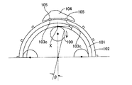
いま、遊星ギヤからインターナルギヤ、外筒体を順次通じてセンターケースに到るトルク伝達の様子を模式説明図である図9、図10を参照して説明する。図9は従来の回り止め突起、図10はこの発明の回り止め突起の一例を示す模式図である。 Now, the state of torque transmission from the planetary gear through the internal gear and the outer cylinder to the center case will be described with reference to FIGS. FIG. 9 is a schematic view showing an example of a conventional anti-rotation protrusion, and FIG. 10 is an example of an anti-rotation protrusion of the present invention.
100は遊星ギヤ、101はインターナルギヤ、102は外筒体、103a、103bは外筒体102の係止用突部、104はセンターケース、105はセンターケース104の回り止め用の溝部である。簡単化のために遊星ギヤ100は一対の係止用突部103a、103bの中間位置に一個だけ図示されている。遊星ギヤ100はインターナルギヤ101のトルク授受内歯を示す点xにてインターナルギヤ101を周方向すなわちy方向へ付勢する。すると、この付勢力により、外筒体102の周方向各部のうち、遊星ギヤ100と係止用突部103aとの間の円弧部分は径外方向Aへ膨らむように付勢され、遊星ギヤ100と係止用突部103bとの間の円弧部分は径内方向Bへ凹むように付勢される。これは、外筒体102の真円性が低下し、その結果として、楕円変形によりインターナルギヤ101と外筒体102との間の各部面圧が変動し、最終的に滑りトルクのばらつきや外筒体の内周面の偏摩耗が生じることを意味する。
100 is a planetary gear, 101 is an internal gear, 102 is an outer cylinder, 103a and 103b are locking protrusions of the
つまり、遊星ギヤ機構、特に大きな衝撃トルクが発生するスタータ用の遊星ギヤ機構にこの外筒体嵌着型衝撃吸収機構を採用する場合、インターナルギヤ上のトルク授受点が少ないために、外筒体に径方向への曲げ応力が生じるわけである。この外筒体嵌着型衝撃吸収機構の滑りトルクは、インターナルギヤと外筒体との間の面圧×摩擦接合面積に比例するため、上記曲げ応力により面圧が大幅に変動し、安定した滑りトルク値が得られない。 In other words, when this outer cylinder-fitted shock absorbing mechanism is employed in a planetary gear mechanism, particularly a planetary gear mechanism for a starter that generates a large impact torque, there are few torque transfer points on the internal gear. Bending stress in the radial direction is generated in the body. The sliding torque of this outer cylinder fitting type shock absorbing mechanism is proportional to the surface pressure between the internal gear and the outer cylinder x frictional joint area. The obtained slip torque value cannot be obtained.
つまり、本発明者らは、従来の外筒体嵌着型衝撃吸収機構における滑りトルク変動や偏摩耗の原因が、外筒体とセンターケースとの間の係止用突部103a、103bの数が少ないために、トルク発生点xであるトルク授受内歯と、係止用突部103a、103bとの間の角度が大きいので、外筒体が受けた力の方向を大きく変更する必要があり、そのため外筒体が径方向外側及び内側に曲がってその真円度が低下するためであることを見いだした。
In other words, the present inventors have found that the cause of slip torque fluctuation and uneven wear in the conventional outer cylinder-fitted shock absorbing mechanism is the number of
参考発明は、上記問題認識に基づいて行われたものであり、外筒体の係止用突部を周方向一定ピッチで、遊星ギヤの数の同数以上設ける。このようにすれば、図10に示すように、係止用突部103cの位置であるトルク受容点と、トルク授受内歯の位置であるトルク発生点xとの間の角度が小さく、トルク発生点xで遊星ギヤ100からインターナルギヤ101を通じて外筒体102に伝達されたトルクは、トルク発生点xを周方向に挟んでトルク発生点xに近接するトルク受容点としての一対の係止用突部103cに分散受承され、外筒体102はほとんど径方向の曲げ力を受けることがない。
The reference invention is made on the basis of the above problem recognition, and the protrusions for locking the outer cylindrical body are provided at a constant pitch in the circumferential direction or more than the number of planetary gears. In this way, as shown in FIG. 10, the angle between the torque receiving point that is the position of the
これは、トルク発生点xと係止用突部103cとが近接しているため、両者の間の角度θが小さく、トルク発生点xにおける力Yの方向と係止用突部103cにおける力の方向とが略等しくなるためである。
This is because the torque generation point x and the
また、この参考発明によれば、上記した滑りトルクの変動や偏摩耗を抑止しつつ外筒体が係止用突部を一定ピッチで多数もつために外筒体の厚さを薄くすることができるため、外筒体嵌着型衝撃吸収機構の小型軽量化と製造コストの低減を実現することもできる。 In addition, according to this reference invention, the thickness of the outer cylindrical body can be reduced because the outer cylindrical body has a large number of locking projections at a constant pitch while suppressing the above-described variation in slip torque and uneven wear. Therefore, it is possible to reduce the size and weight of the outer cylinder-fitted impact absorbing mechanism and reduce the manufacturing cost.
更に、この参考発明によれば、係止用突部の個数増大に応じて一個の係止用突部が負担するトルクを減らすことができるので、係止用突部の径方向高さを短縮することができ、その分だけ外筒体嵌着型衝撃吸収機構をもつ遊星ギヤ機構の小型軽量化も実現することができる。 Furthermore, according to this reference invention, since the torque borne by one locking projection can be reduced as the number of locking projections increases, the radial height of the locking projection is shortened. Accordingly, the planetary gear mechanism having the outer cylinder-fitting type shock absorbing mechanism can be reduced in size and weight.
好適な態様において、前記外筒体の係止用突部は、前記インターナルギヤの内歯ピッチに略等しいピッチで前記外筒体の外周面に形成されている。なお、ここで言う「略等しい」とは、0.5〜2.0倍を意味するものとする。このようにすれば、外筒体はほぼインターナルギヤに等しい数の係止用突部をもつため、インターナルギヤのどの内歯がトルク授受内歯となったとしても確実に内歯に対して周方向に略一致する係止用突部によりトルクを受容することができるので外筒体の曲げにより派生する上記問題はほとんど解消することができ、信頼性に優れ薄肉で小型軽量な外筒体嵌着型衝撃吸収機構を実現することができる。 In a preferred aspect, the locking protrusions of the outer cylinder are formed on the outer peripheral surface of the outer cylinder at a pitch substantially equal to the internal gear pitch of the internal gear. Here, “substantially equal” means 0.5 to 2.0 times. In this way, since the outer cylinder has the same number of locking projections as the internal gear, no matter which internal tooth of the internal gear becomes the torque transfer internal tooth, Because the torque can be received by the locking projections that substantially coincide with the circumferential direction, the above problems derived from the bending of the outer cylinder can be almost eliminated, and the thin, small, and lightweight outer cylinder is excellent in reliability. A body fitting type shock absorbing mechanism can be realized.
好適な態様において、前記外筒体の係止用突部は、ギヤ形状を有している。このようにすれば、外筒体の係止用突部をインターナルギヤの内歯と同じ歯切り加工装置により製造することができるため、製造工程を簡素化することができる。 In a preferred aspect, the locking projection of the outer cylinder has a gear shape. By doing so, the locking projection of the outer cylinder can be manufactured by the same gear cutting device as the internal teeth of the internal gear, so that the manufacturing process can be simplified.
好適な態様において、前記外筒体に前記係止用突部を形成した後、前記外筒体の内周面を硬化するための熱処理加工を行う。このようにすれば、外筒体の内周面の耐摩耗性の向上の他、外筒体の曲げ剛性も向上することができ、係止用突部の強度も向上することができる。更に、この態様では、前記熱処理加工において、前記外筒体の両周面に形成された硬化用熱処理層の厚さに対して、1〜2倍の厚さの非熱処理層を前記外筒体の内部に残す。このようにすれば、いたずらに外筒体の径方向厚を増大することなく上記した外筒体の耐曲げ強度や耐摩耗性を確保しつつ粘り強さすなわち靱性も確保することができる。更に外筒体を薄肉化することにより、所定の滑りトルクを得る締代幅を大きく取れるため(例えば研磨公差を大きくできる)ため外筒体の製造が容易となる。たとえば、150Nmの滑りトルクを得るために、外筒体の硬化用熱処理層の深さ(ここでは浸炭深さとする)を0.8mmとすれば、外筒体の係止用突部の無い部位での厚さTo は、0.8x3=2.4〜3.2mmとされ、嵌合公差幅は60〜70μmを確保することができる。 In a preferred embodiment, after forming the locking projection on the outer cylinder, a heat treatment process for curing the inner peripheral surface of the outer cylinder is performed. In this way, in addition to improving the wear resistance of the inner peripheral surface of the outer cylindrical body, the bending rigidity of the outer cylindrical body can be improved, and the strength of the locking projection can also be improved. Furthermore, in this aspect, in the heat treatment, a non-heat treatment layer having a thickness of 1 to 2 times the thickness of the heat treatment layer for curing formed on both peripheral surfaces of the outer cylinder is provided in the outer cylinder. Leave inside. If it does in this way, tenacity, ie, toughness, can be ensured, ensuring the bending strength and abrasion resistance of the above-mentioned outer cylinder, without unnecessarily increasing the radial thickness of the outer cylinder. Further, by reducing the thickness of the outer cylindrical body, it is possible to increase the tightening margin for obtaining a predetermined slip torque (for example, increase the polishing tolerance), so that the outer cylindrical body can be easily manufactured. For example, in order to obtain a sliding torque of 150 Nm, if the depth of the heat treatment layer for hardening of the outer cylinder (in this case, the carburization depth) is set to 0.8 mm, the outer cylinder has a portion without a locking projection. The thickness To is 0.8 × 3 = 2.4 to 3.2 mm, and a fitting tolerance width of 60 to 70 μm can be secured.
好適な態様において、前記外筒体の前端部は、前記インターナルギヤの前端面に沿って径方向内側に延在して、インターナルギヤ抜け止め部材として、前記インターナルギヤの軸方向前方への移動を規制する内鍔部を有することを特徴としている。これにより、インターナルギヤの抜け止めを図ることができるととともに、外筒体の剛性低下を抑止しつつ外筒体の薄肉化を実現することができる。 In a preferred aspect, the front end portion of the outer cylindrical body extends radially inward along the front end surface of the internal gear, and serves as an internal gear retaining member forward in the axial direction of the internal gear. It is characterized by having an inner flange that restricts the movement of the inner wall. As a result, it is possible to prevent the internal gear from coming off, and it is possible to reduce the thickness of the outer cylindrical body while suppressing a decrease in rigidity of the outer cylindrical body.
好適な態様において、前記インターナルギヤの前端部は、前記外筒体の前端面に沿って径方向外側に延在して、前記センターケースの溝部に軸方向前方への変位不能に嵌入される輪板状の外鍔部を有することを特徴としている。これにより、インターナルギヤの抜け止めを図ることができるととともに、インターナルギヤの剛性低下を抑止しつつ外筒体の薄肉化を実現することができる。 In a preferred aspect, the front end portion of the internal gear extends radially outward along the front end surface of the outer cylindrical body, and is fitted into the groove portion of the center case so as not to be displaced forward in the axial direction. It is characterized by having a ring plate-like outer flange. As a result, it is possible to prevent the internal gear from coming off, and it is possible to reduce the thickness of the outer cylindrical body while suppressing a decrease in the rigidity of the internal gear.
上記目的を達成する第1発明の外筒体嵌着型衝撃吸収機構を有する遊星ギヤ機構減速式スタータは、前記外筒体の内周面、又はインターナルギヤの外周面は、軸方向中央部に位置して互いに摩擦結合する接触面部と、この接触面部の端から前記内周面、又は外周面の軸方向端に向けてテーパ状に面取りしてなる嵌合案内面部とを有し、前記接触面部及び嵌合案内面部は、固体性潤滑膜により覆設されていることを特徴としている。ただし、嵌合案内面部は、軸方向に少なくとも1mm以上設けられ、かつ、嵌合案内部の径方向面取り寸法は少なくとも固体潤滑膜の厚さ(通常は10〜30μm)以上とされる。 The planetary gear mechanism decelerating starter having the outer cylinder-fitting type impact absorbing mechanism of the first invention that achieves the above object is characterized in that the inner peripheral surface of the outer cylindrical body or the outer peripheral surface of the internal gear is an axially central portion. A contact surface portion that is frictionally coupled to each other, and a fitting guide surface portion that is chamfered in a tapered shape from the end of the contact surface portion toward the inner peripheral surface or the axial end of the outer peripheral surface, The contact surface portion and the fitting guide surface portion are covered with a solid lubricating film. However, the fitting guide surface portion is provided at least 1 mm or more in the axial direction, and the radial chamfer dimension of the fitting guide portion is at least the thickness of the solid lubricating film (usually 10 to 30 μm).
すなわち、この第1発明では、たとえば二硫化モリブデンや有機モリブデンなどの無機材料又は有機材料からなる固体潤滑膜を嵌合面すなわち外筒体の内周面又はインターナルギヤの外周面に形成する。好適には、この固体潤滑膜は、上記嵌合案内面部や接触面部を化成皮膜処理して固体潤滑材保持のために粗面化した後でコーティングされる。これにより、従来のグリス潤滑における潤滑剤補給又は保持のための種々の機構を省略することができるため、小型で製造が容易な外筒体嵌着型衝撃吸収機構を実現することができる。 That is, in the first invention, a solid lubricating film made of an inorganic material or an organic material such as molybdenum disulfide or organic molybdenum is formed on the fitting surface, that is, the inner peripheral surface of the outer cylinder or the outer peripheral surface of the internal gear. Preferably, the solid lubricant film is coated after the fitting guide surface portion and the contact surface portion are subjected to a chemical conversion film treatment to roughen the surface to hold the solid lubricant. As a result, various mechanisms for supplying or holding the lubricant in the conventional grease lubrication can be omitted, so that it is possible to realize a small and easy to manufacture outer cylinder fitting type shock absorbing mechanism.
なお、上記した固体潤滑膜を摺動面にコーティングすること自体は公知技術である。ただし、本発明が適用される遊星ギヤ機構減速式スタータの外筒体嵌着型衝撃吸収機構では、滑りトルク確保のために外筒体とインターナルギヤとの間の嵌合クリアランスが非常に狭いため、両者の嵌合時に、径方向内側の部材(嵌入部材)であるインターナルギヤの外周面と端面との間の角部が径方向外側の部材(嵌着部材)である外筒体の内周面を傷つけたり、逆に、外筒体の内周面と端面との間の角部がインターナルギヤの外周面を傷つけたりする問題が発生する。このような場合、これらの周面に固体潤滑膜が存在すると、この固体潤滑膜が傷付き、この部位から固体潤滑膜の傷が拡大するため、従来の外筒体嵌着型衝撃吸収機構をもつ遊星ギヤ機構減速式スタータでは、固体潤滑膜をインターナルギヤと外筒体との間に用いることが困難であった。 It is a known technique to coat the sliding surface with the above-described solid lubricating film. However, in the planetary gear mechanism decelerating starter outer shock absorption mechanism to which the present invention is applied, the fitting clearance between the outer cylinder and the internal gear is very narrow in order to secure the sliding torque. Therefore, at the time of fitting both, the corner portion between the outer peripheral surface and the end surface of the internal gear, which is a radially inner member (inserting member), is a radially outer member (fitting member) of the outer cylindrical body There is a problem that the inner peripheral surface is damaged, or conversely, the corner portion between the inner peripheral surface and the end surface of the outer cylindrical body damages the outer peripheral surface of the internal gear. In such a case, if there is a solid lubricating film on these peripheral surfaces, the solid lubricating film will be damaged, and the damage of the solid lubricating film will expand from this part. In the planetary gear mechanism decelerating starter having a solid lubricant film, it is difficult to use the solid lubricant film between the internal gear and the outer cylinder.
そこで、この第1発明では、インターナルギヤの外周面角部及び外筒体の内周面角部をテーパ状に面取りして嵌合案内面部とし、嵌合時にこれら角部が相手側の周面を傷付けるのを防止する工夫を行っている。これにより、外筒体嵌着型衝撃吸収機構をもつ遊星ギヤ機構減速式スタータにおいても外筒体とインターナルギヤとの間の嵌合面に固体潤滑膜を採用することができ、特に潤滑グリスの保持、補給機構の省略を実現することができ、構造の簡素化と製造及び保守の容易化を実現することができる。 Therefore, in the first aspect of the invention, the corners of the outer peripheral surface of the internal gear and the inner peripheral surface of the outer cylinder are chamfered into a fitting guide surface portion, and these corner portions are fitted on the other side when mating. We are trying to prevent the surface from being damaged. As a result, even in a planetary gear mechanism decelerating starter having an outer cylinder-fitted shock absorbing mechanism, a solid lubricating film can be employed on the mating surface between the outer cylinder and the internal gear. Therefore, it is possible to omit the holding and replenishment mechanism, and to simplify the structure and facilitate manufacturing and maintenance.
なお、この発明の嵌合案内面部は、インターナルギヤの外周面と外筒体の内周面のどちらか一方に設ければよいが、インターナルギヤの外周面と外筒体の内周面との両方に設けると、嵌合時の傷防止効果を一層向上することができる。また、インターナルギヤの外周面両側や外筒体の内周面両側にこれら嵌合案内面部を設けると、製造時に面合わせが不要となるため製造が容易となる。 The fitting guide surface portion of the present invention may be provided on either the outer peripheral surface of the internal gear or the inner peripheral surface of the outer cylindrical body, but the outer peripheral surface of the internal gear and the inner peripheral surface of the outer cylindrical body. If both are provided, the effect of preventing scratches during fitting can be further improved. In addition, when these fitting guide surface portions are provided on both the outer peripheral surface of the internal gear and the inner peripheral surface of the outer cylinder, the surface alignment becomes unnecessary at the time of manufacturing, which facilitates manufacturing.
好適な態様において、異なる滑りトルクを与えるために前記嵌合案内部の軸方向幅を変更する。すなわち、遊星ギヤ機構減速式スタータの機種ごとに滑りトルク値を変更する場合に、インターナルギヤや外筒体の径寸法や軸寸法を一定としておき、嵌合案内面部の軸方向幅を変更すれば、簡単にこの滑りトルク変更に対応することができ、実質的に部品又はその半製品の種類を減らすことができる。 In a preferred embodiment, the axial width of the fitting guide portion is changed in order to give different sliding torque. That is, when changing the slip torque value for each model of planetary gear mechanism reduction starter, keep the diameter and shaft dimensions of the internal gear and outer cylinder constant, and change the axial width of the fitting guide surface. Thus, it is possible to easily cope with the change of the sliding torque, and substantially reduce the types of parts or semi-finished products thereof.
第2発明の外筒体嵌着型衝撃吸収機構を有する遊星ギヤ機構減速式スタータは、前記外筒体の前端面及びインターナルギヤの前端面は、第1のワッシャを介して前記センターケースの段差端面に支承され、前記外筒体の後端面及びインターナルギヤの後端面は、少なくとも第2のワッシャを介して前記モータのヨークの端面に支承され、前記ヨークは、スルーボルトにより前記センターケースに締結されていることを特徴としている。 The planetary gear mechanism decelerating starter having the outer cylinder fitting type shock absorbing mechanism of the second invention is characterized in that the front end surface of the outer cylinder and the front end surface of the internal gear are connected to the center case via a first washer. The rear end surface of the outer cylinder and the rear end surface of the internal gear are supported by at least a second washer on the end surface of the motor yoke, and the yoke is connected to the center case by a through bolt. It is characterized by being fastened to.
すなわち、この第2発明では、外筒体をモータのヨークの端面とセンターケースの段差面とに挟設し、ヨークとセンターケースとをスルーボルトにより締結する際に固定する。また、外筒体の両端面に接しつつ径方向内側にワッシャを延在させ、これら一対のワッシャによりインターナルギヤの軸方向変位を防止する。インターナルギヤの軸方向変位のための構造を実質的に省略することができるため、構造の簡素化と装置の小型軽量化を実現することができる。また、外筒体を単純な円筒形状とすることができるので、嵌合部の面圧を均一化でき嵌合部の潤滑寿命を延長することができる。 That is, in the second invention, the outer cylinder is sandwiched between the end surface of the motor yoke and the step surface of the center case, and is fixed when the yoke and the center case are fastened by the through bolts. Further, a washer is extended radially inward while being in contact with both end faces of the outer cylinder, and the axial displacement of the internal gear is prevented by the pair of washers. Since the structure for axial displacement of the internal gear can be substantially omitted, simplification of the structure and reduction in size and weight of the apparatus can be realized. Further, since the outer cylindrical body can be made into a simple cylindrical shape, the surface pressure of the fitting portion can be made uniform, and the lubrication life of the fitting portion can be extended.
本発明のスタータの好適な実施形態を図面を参照して以下に説明する。ただし、本発明は下記の実施形態に限定されるものではなく、本発明の技術思想を他の公知技術又はそれと必要機能が共通するその他の技術を組み合わせて構成できることはもちろんである。 A preferred embodiment of the starter of the present invention will be described below with reference to the drawings. However, the present invention is not limited to the following embodiments, and it is a matter of course that the technical idea of the present invention can be configured by combining other known techniques or other techniques having the same functions as those of other known techniques.
(全体構造)
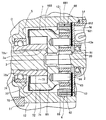
この実施例のスタータは、後述する筒状体を除いて基本的に周知となっている通常の遊星ギヤ機構減速式スタータと同一構造をもつため、スタータ全体構造については、図面を用いずに簡単に説明し、要部のみ、図1に示す要部軸方向断面図及び図2のその要部拡大軸方向断面図を用いて説明するものとする。
(Overall structure)
The starter of this embodiment has the same structure as an ordinary planetary gear mechanism reduction starter that is basically well-known except for a cylindrical body to be described later. Therefore, the entire starter structure is simplified without using the drawings. Only the main part will be described with reference to the main part axial sectional view shown in FIG. 1 and the main part enlarged axial sectional view of FIG.
スタータは、モータ2、出力シャフト3、ピニオンギヤ4、マグネットスイッチ5、遊星ギヤ機構6、一方向クラッチ7、シフトレバー8を有し、ピニオンギヤ4はエンジン側のリングギヤ9に近接配置されている。
The starter includes a
(ハウジング)
これらの構成要素を収容するスタータハウジングは、後端が開口された略椀状部材であるフロントフレーム11と、センターケース12、鍔付き円筒形状の隔壁板13、両端が開口された円筒形状のヨーク14、前端が開口された略椀状部材であるエンドフレームにより構成され、前記した順序で軸方向前側から後ろ側へ順に配置されている。センターケース12は、上側にマグネットスイッチ5を収容するための後端開口のスイッチ収容室を有し、下側に遊星ギヤ機構6と一方向クラッチ7とを収容する後端開口のトルク伝達機構収容室Sを有している。ヨーク14とエンドフレーム15とは内部にモータ2を収容するためのモータ室Mを有している。フロントフレーム11は内部にシフトレバー室Cを有している。
(housing)
The starter housing that accommodates these components includes a
フロントフレーム11とエンドフレーム15とは、センターケース12及びヨーク14を軸方向に挟んでスルーボルト16により固定されている。これにより、隔壁板13は、センターケース12とヨーク14とにより軸方向に挟圧されてセンターケース12の上述したトルク伝達機構収容室Sとヨーク14の上述したモータ室Mとを遮断している。
The
フロントフレーム11のシフトレバー室Cにはシフトレバー8が、センターケース12のトルク伝達機構収容室Sには遊星ギヤ機構6及び一方向クラッチ7が、センターケース12の上記スイッチ室にはマグネットスイッチ5が、ヨーク14及びエンドフレーム15の内部にはモータ2が、それぞれ収容されている。
The shift lever chamber C of the
(モータ2)
モータ2はモータ回転軸20を有する直流モータである。モータ回転軸20は隔壁板13とエンドフレーム15とに軸受けを介して回転自在に支持されている。ヨーク14には界磁コイル及びアーマチャが、エンドフレーム15には整流子及びブラシ等が収容されている。ただし、ヨーク14は、モータ2の静止継鉄部材としてモータ2の磁気回路の一部を構成している。アーマチャ及び整流子はモータ回転軸20に固定され、モータ回転軸20の先端部は隔壁板13を貫通してセンターケース12のトルク伝達機構収容室Sに突出している。モータ2自体は周知であり、これ以上の説明は省略する。
(Motor 2)
The
(遊星ギヤ機構6)
センターケース12の下部には隔壁板13に隣接して遊星ギヤ機構6が収容されている。遊星ギヤ機構6は、モータ回転軸20の先端部に形成されたサンギヤ61と、リング状のインターナルギヤ62と、両ギヤ61、62に噛合する複数の遊星ギヤ63と、遊星ギヤ63を軸受けを介して回転自在に支持する遊星ギヤピン64と、遊星ギヤピン64が固定されるキャリヤ65と、センターケース12に嵌入されてインターナルギヤ62に嵌着された外筒体66とにより構成されており、モータ回転軸20の回転速度を遊星ギヤ63の公転速度まで減速する。遊星ギヤピン64は、キャリヤ65の穴に圧入されて固定されている。この実施例ではキャリヤ65は後述する一方向クラッチ7のクラッチアウタ71と一体化されている。外筒体66については、この実施例の特徴をなすため後で詳細に説明するものとする。
(Planetary gear mechanism 6)
The planetary gear mechanism 6 is accommodated in the lower part of the
(一方向クラッチ7)
一方向クラッチ7は、遊星ギヤ機構6のキャリヤ65と一体化されたクラッチアウタ71と、クラッチアウタ71の径方向内側に配置されていわゆるクラッチインナを構成する略円筒形状のチューブ72と、クラッチアウタ71の内周面に形成されたくさび状のカム室に不図示のローラスプリングとともに収容されたクラッチローラ73等より構成されている。クラッチローラ73は、クラッチアウタ71の内周面から伝達されたトルクをチューブ72の外周面に伝達する。
(One-way clutch 7)
The one-
クラッチアウタ71は、軸受けを介してモータ回転軸20の先端部に相対回転自在に嵌着されている。クラッチアウタ71は前方に開口する凹部を有する椀状部材であって、その底部が上述のキャリヤ65を構成している。クラッチアウタ71には出力シャフト3の後端面に軸方向に対面する面に図示省略したスラストワッシャ(図示せず)を設けているが、出力シャフト3の後端面とモータ回転軸20の前端面との間にはスラスト伝達を遮断するために間隙が確保されている。
The clutch outer 71 is fitted to the tip of the
チューブ72は、軸方向前端側に突出する軸受部72aを有している。軸受部72aは、ボールベアリング74を介してセンターケース12の前端部に回転自在に支持されている。ボールベアリング74は、軸受部72aを内輪として利用することにより、チューブ72と一体的に設けられている。
The
クラッチアウタ71の前端開口はワッシャ75によりクラッチローラ73の脱出を防止するべく閉鎖され、ワッシャ75はカバー76により固定されている。
The front end opening of the clutch outer 71 is closed by a
(出力シャフト3)
チューブ72には出力シャフト3の後端部が軸方向進退可能に嵌入されており、チューブ72の軸受部72aは、出力シャフト3を軸方向進退可能かつこの実施例では相対回転自在に支持している。チューブ72の内周面には、軸受部72aからチューブ72の後端まで雌ヘリカルスプライン72cが形成されている。ただし、軸受部72aの前端部から雌ヘリカルスプライン72cの前端部までは雌ヘリカルスプライン72cは形成されず、これにより、雌ヘリカルスプライン72cの前端部は、出力シャフト3がエンジン側(図1の左側)へ移動した時に出力シャフト3の移動を規制するための前端ストッパとして機能するようになっている。この前端ストッパ機能は別の場所に設けてもよいことはもちろんである。出力シャフト3の前端部は、フロントフレーム11に軸受を介して回転自在、且つ摺動自在に支持されている。出力シャフト3の後端部の外周面には、チューブ72の雌ヘリカルスプライン72cに嵌合する雄ヘリカルスプライン3aが形成されている。
(Output shaft 3)
The rear end portion of the
13aは、隔壁板13の前端面に当接しつつ径方向に延在するスラストワッシャであり、遊星ギヤピン64を通じて出力シャフト3の後退スラストを受承する。なお、このスラストワッシャ13aは更に径方向外側に延設して、後述する外筒体66と隔壁板13とにより挟設してもよい。スラストワッシャ13aは、輪板形状に形成された耐摩耗性部材であって、出力シャフト3がシフトレバーにより後退させられる際に出力シャフト3から最終的に遊星ギヤピン64に伝達される後方へのスラストを、このスラストワッシャ13aにより受承することができる。その結果、出力シャフト3の惰性回転エネルギーを、遊星ギヤピン64とスラストワッシャ13aとの摩擦により良好に消耗させて、出力シャフト3の回転を速やかに停止させることができる。
13 a is a thrust washer that extends in the radial direction while contacting the front end surface of the
(ピニオンギヤ4)
ピニオンギヤ4は、フロントフレーム11から前方へ突き出た出力シャフト3の前端部に軸方向相対移動可能、相対回転不能にスプライン嵌合しており、ピニオンギヤと出力シャフト3との間に配設されたピニオンスプリングに付勢されて出力シャフト3上を前方へ付勢されている。出力シャフト3の先端部には、ピニオンギヤ4の前進を規制するカラーが取り付けられている。
(Pinion gear 4)
The pinion gear 4 is spline-fitted to the front end portion of the
(マグネットスイッチ)
センターケース12はマグネットスイッチ5とその下方の一方向クラッチ7及び遊星ギヤ機構6とを区画分離している。マグネットスイッチ5のプランジャの前端部はフロントフレーム11の内部に突出している。マグネットスイッチ5は、エンジン始動スイッチの閉動によりバッテリから通電される励磁コイルと、この励磁コイルの発生する磁力により吸引されるプランジャと、励磁コイルへの通電が停止されて磁力が消滅した時にプランジャを押し戻すためのリターンスプリング等より構成されているが、周知である通常のものと同じであるため説明を省略する。
(magnetic switch)
The
(シフトレバー8)
シフトレバー8は、センターケース12に固定されたレバーホルダにより揺動自在に支持されており、シフトレバー8の上端部はマグネットスイッチ5のプランジャの前端部にフックで連結され、シフトレバー8の下端部は出力シャフト3に設けられた一組のワッシャの間に係合されて、プランジャの動きを出力シャフト3に伝達することにより、出力シャフト3を軸方向に進退させる。
(Shift lever 8)
The
(動作説明)
エンジン始動スイッチの閉操作によりマグネットスイッチ5の励磁コイルに通電されると、プランジャが後方へ吸引され、プランジャはシフトレバー8を介して出力シャフト3を前方へ押し出す。
(Description of operation)
When the exciting coil of the magnet switch 5 is energized by closing the engine start switch, the plunger is attracted backward, and the plunger pushes the
ピニオンギヤ4がエンジンのリングギヤ9にスムーズに噛み合った場合には、マグネットスイッチ5の可動接点が一組の固定接点に当接し、モータ2に通電されてモータ2が回転する。ピニオンギヤ4がリングギヤ9に噛み合うことなくリングギヤ9に衝突した場合は、ピニオンスプリングを押し縮めながら出力シャフト3だけが更に前進し、これによりピニオンギヤ4が出力シャフト3上を相対的に後退する。この時、出力シャフト3の移動に伴ってピニオンギヤ4がリングギヤ9と噛み合い可能な位置まで回転し、ピニオンスプリングの反力により、ピニオンギヤ4が押し出されてリングギヤ9に噛み合い、その後、マグネットスイッチ5の固定接点が可動接点に当接してモータ2は回転力を発生する。ピニオンギヤ4とリングギヤ9との噛み合いが完了すると、ピニオンギヤ4からリングギヤ9に回転力が伝達されてエンジンをクランキングする。
When the pinion gear 4 meshes smoothly with the ring gear 9 of the engine, the movable contact of the magnet switch 5 comes into contact with a set of fixed contacts, the
エンジン始動後、エンジン始動スイッチが開動されると、マグネットスイッチ5の励磁コイルへの通電停止により磁力が消滅するため、プランジャがリターンスプリングの反力で押し戻され、マグネットスイッチ5の可動接点が固定接点から離れてモータ2への通電が停止される。また、プランジャが押し戻されるとシフトレバー8を介して出力シャフト3が戻されるため、出力シャフト3の後端面がクラッチアウタ71に摺接して停止する。
When the engine start switch is opened after the engine is started, the magnetic force disappears due to the energization stop of the magnet coil 5 exciting coil, so that the plunger is pushed back by the reaction force of the return spring, and the movable contact of the magnet switch 5 becomes the fixed contact. Away from the power supply to the
(外筒体66)
この実施例の特徴をなす外筒体66について、図2及び図3を参照して以下に説明する。図3は外筒体66の一部拡大径方向断面図である。
(Outer cylinder 66)
The
外筒体66は、図1、図2に示すように、両端開口の円筒状部材であって、インターナルギヤ62に嵌着されてインターナルギヤ62の外周面に嵌着された円筒形状の主筒部661と、主筒部661の外周面に周方向所定ピッチで突設された回り止め突起662とからなる。各回り止め突起662は軸方向に延在しているが、螺旋状に形成されていても構わない。主筒部661の内周面は、インターナルギヤ62の外周面に摩擦結合している。
As shown in FIGS. 1 and 2, the outer
回り止め突起662は、図3に示すように径方向においてギヤ形状に形成されており、センターケース12の後端開口近傍の内周面に凹設された回り止め溝部121に歯合している。したがって、回り止め溝部121の数は、回り止め突起662の数に等しい。なお、回り止め突起662の径方向形状はギヤ形状に限定されるものではない。
As shown in FIG. 3, the
8は、インターナルギヤ62の軸方向変位を規制する輪板状の抜け止めワッシャであって、外筒体66の前端面に沿いつつ延設されている。抜け止めワッシャ8の外周部は、外筒体66の主筒部661の前端面と回り止め溝部121の奥端面とにより挟圧、固定されている。これにより、抜け止めワッシャ8は、インターナルギヤ62の前方への移動を規制することができる。なお、抜け止めワッシャ8の径方向内端は遊星ギヤ63の歯頂よりも径方向外側に位置していることが好適である。
8 is a ring-shaped retaining washer that restricts the axial displacement of the
外筒体66の後端面は、スラストワッシャ13aの前端面に当接しており、具体的には、図示しないスルーボルトの締結により、抜け止めワッシャ8、外筒体66、スラストワッシャ13a及び隔壁板13は、ヨーク14とセンターケース12とにより軸方向に挟圧、固定されている。その結果、インターナルギヤ62の後端面はスラストワッシャ13aに当接するため、インターナルギヤ62の回動が生じても、隔壁板13が摩耗することがない。また、遊星ギヤピン64を通じて出力シャフト3の後退スラストを受承するスラストワッシャ13aは、外筒体66及びワッシャ8とともにスルーボルトにより挟圧固定されるため、外筒体66、ワッシャ8及びスラストワッシャ13aの固定のためのセンターケース12側の溝加工を簡単に行うことができる。なお、ワッシャ8の外周部には外筒体66の回り止め突起662と同様の回り止め突起を設けることができる。これにより、インターナルギヤ62との連れ回りによるワッシャ8の回転を規制することができる。同様に、スラストワッシャ13aや隔壁板13の外周部に外筒体66の回り止め突起662と同様の回り止め突起を設けることができる。
The rear end surface of the outer
以下、この実施例において重要な点を順次説明する。 Hereinafter, important points in this embodiment will be described sequentially.
(回り止め突起662の個数)
まず、この実施例では、外筒体66の外周面に突設される回り止め突起662の個数は、少なくとも遊星ギヤ63の個数の2倍以上で、遊星ギヤ63の個数は3個以上とされている。更に好適には、外筒体66の回り止め突起662の数をインターナルギヤ62の内歯ピッチと0.5〜2.0倍とされる。このようにすれば、既述したように、大きなトルクがインターナルギヤ62に入力した場合でも、遊星ギヤ63からトルクを受ける内歯は周方向に近接する外筒体66の回り止め突起662にトルクを伝達することができるため、既述した外筒体66の湾曲によるその真円度の低下を防止することができる。その結果、外筒体66の内周面とインターナルギヤ62の外周面との間の各部面圧がばらついて、楕円変形による偏摩耗が生じたり、滑りトルク値が変動したりするという問題を良好に抑止することができる。また、外筒体66やインターナルギヤ62の最小径方向厚さを減らすことができるため、遊星ギヤ機構6やそれを囲包するセンターケース12の小型軽量化を実現することもできる。なお、上記では、回り止め突起662を遊星ギヤ63の個数の2倍以上としているが、遊星ギヤ63と同数以上でも良い。
(Number of locking protrusions 662)
First, in this embodiment, the number of the rotation-preventing
(外筒体66の厚さ)
この実施例によれば、外筒体66の回り止め突起662を上記説明したように多数設けたことにより外筒体66への局部的な応力集中や変形を減らすことができるので、外筒体66の径方向厚さを従来より格段に縮小することができる。なお、ここで言う外筒体66の厚さとは、回り止め突起662が無い部位における外径と内径との距離であり、この実施例では、図3に示す歯底厚Toを意味するものとする。
(Thickness of outer cylinder 66)
According to this embodiment, the provision of a large number of
外筒体66の厚さを薄くできると言うことは、製造上、外筒体66の内径の許容公差を大きくすることができるため、外筒体66の製造及びその組み立て(組み立て)が格段に容易となるという効果を生じる。以下、更に説明する。
The fact that the thickness of the outer
この現象を更に詳しく説明する。 This phenomenon will be described in more detail.
この実施例の外筒体66とインターナルギヤ62との円筒面の摩擦接触において、滑りトルクは、面圧×摩擦接触面積×径(中心軸から摩擦円筒面までの距離)に比例する。すなわち滑りトルクは面圧に比例し、この面圧は外筒体66の内周面とインターナルギヤ62の外周面との間の締代に依存することは容易にわかる。外筒体66はインターナルギヤ62の外周面に圧入により嵌着されるが、外筒体66の肉厚が薄いと外筒体66の径方向の弾性変形が容易となるために、所定の許容面圧変化範囲における嵌合締代の範囲は大きくなる。なお、ここで言う嵌合締代とは、外筒体66の内周面の径の許容公差を言うものとする。この所定の許容面圧変化範囲は、上記した滑りトルクが面圧×摩擦接触面積×径に比例することから、所定の許容滑りトルク範囲に相当する。この実施例における滑りトルクの許容範囲はあらかじめ決まっている。結局、一定の滑りトルクの許容範囲を維持する条件下においてる嵌合締代は、外筒体66の最小肉厚(最小径幅または歯底幅とも言う)Toが小さくなるほど大きくすることができる。
In the frictional contact between the outer
このことを、図4の滑りトルク嵌合締代特性図を用いて図示する。図4において、縦軸は滑りトルクTの値を、横軸は嵌合締代の量を示す。T1、T2、T3、T4は、外筒体66の最小径幅Toをその熱処理硬化層(一面分)の厚さで割った値(比)である。この比を用いるのは、熱処理硬化層の厚さは最低限必要となるため、外筒体66の最小径幅を熱処理硬化層を基準として示すのが便利なためである。T1は2.4、T2は3.2、T3は4.8、T4は5.6である。δ1は外筒体66の最小肉厚Toの比TiがT1(=2.4)、かつ、滑りトルクが許容滑りトルク範囲内にある場合の嵌合締代の範囲を示し、δ5は外筒体66の最小肉厚Toの比Tiが5.6、かつ、滑りトルクが許容滑りトルク範囲内にある場合の嵌合締代の範囲を示す。
This is illustrated using the slip torque fitting tightening characteristic diagram of FIG. In FIG. 4, the vertical axis represents the value of the sliding torque T, and the horizontal axis represents the amount of the fitting tightening allowance. T1, T2, T3, and T4 are values (ratio) obtained by dividing the minimum diameter width To of the outer
実際の製造、特に外筒体66及びインターナルギヤ62の製造と嵌合の工程において所定の嵌合締代が必要であることは明白である。製造に好適な嵌合締代をδ1とする。一方、外筒体66とインターナルギヤ62との間の許容滑りトルクTの範囲ΔTもスタータ仕様において予め定められている値である。また、外筒体66の最小径幅tiは、内周面側の熱処理層の厚さと外周面側の熱処理硬化層の厚さと内部の非熱処理層の厚さの和となる。非熱処理層の厚さの最小値は熱処理硬化層の厚さ以上設定することが必要である。熱処理硬化層の厚さはある最小値以上は必要となる。
It is clear that a predetermined fastening allowance is required in the actual manufacturing, particularly in the manufacturing and fitting processes of the
これらの各条件から、本発明者は、非熱処理層の厚さを熱処理硬化層の厚さの1〜2倍に設定することにより、上記各条件を満足させて、目的とする許容滑りトルクTの範囲をもつ外筒体嵌着型衝撃吸収機構を高度の製造条件を必要とせずに製造可能なことを見出したものである。 From these conditions, the present inventors set the thickness of the non-heat-treated layer to 1 to 2 times the thickness of the heat-treated cured layer, thereby satisfying each of the above conditions, and the desired allowable slip torque T It has been found that an outer cylinder-fitting type impact absorbing mechanism having the following range can be manufactured without requiring high manufacturing conditions.
結局、回り止め突起662を多数設けて外筒体66の最小肉厚Toを減少させることにより、嵌合締代を大幅に増大することができるため外筒体66へのインターナルギヤ62の圧入嵌合を非常に容易とすることができることが理解される。
Eventually, by providing a large number of
更に説明すれば、図4においてT1の場合と、T4の場合当接突起5で比較すると、前者のような外筒体66の薄肉化により図4に示すように嵌合締代の大幅な増大とそれに起因する製造容易性を実現することができる。逆に言えば、外筒体66の最小径幅の増大は嵌合締代の大幅な減少を招いて、外筒体66の製造及び嵌合作業が極めて困難となるわけである。製造において、この嵌合締代を大きく確保できることは、後述する外筒体66の表面硬化処理後の研磨処理における研磨公差を大きくできることを意味する。また、後述するように、外筒体66の内周面に固体潤滑膜を形成する場合には、固体潤滑膜のコーティング前に外筒体66の内周面になされる表面粗面化処理(潤滑剤保持用表面処理)の公差を大きくできることも意味する。
More specifically, in the case of T1 in FIG. 4 and in the case of T4, the contact protrusion 5 is compared, so that the fitting tightening allowance is greatly increased as shown in FIG. And the manufacturing ease resulting from it can be realized. In other words, an increase in the minimum diameter width of the outer
(外筒体66の表面処理)
この実施例によれば、上記したように外筒体66を薄肉化できるものの、外筒体66の内周面は摩擦面であるため耐摩耗性を付与する必要がある。耐摩耗性付与のためには浸炭処理が最も生産性に優れた技法である。また、外筒体66の外周面側も摩耗防止などの理由により同様の熱処理硬化層が同時に形成するのが通常である。しかし、知られているように浸炭処理により外筒体66の表面に熱処理硬化層を形成すると外筒体66の靱性が低下する。この外筒体66の靱性確保のためには外筒体66の内部にすくなくとも表面の熱処理硬化層以上の厚さの熱処理されない未熱処理硬化層を残す必要がある。このことは、熱処理硬化層の厚さを1とする時、外筒体66の最小肉厚Toを3以上とする必要があることがわかる。好適には、外筒体66の最小肉厚Toは熱処理硬化層(浸炭深さ)の3〜5倍とすることが好適であり、更に好適には3〜4倍とされる。これにより、外筒体66を実用可能な最小厚さにすることができるため、製造公差(嵌合締代)の増大、嵌合作業の容易化、更には一方向クラッチ7の小型化を実現することができる。
(Surface treatment of outer cylinder 66)
According to this embodiment, although the
外筒体66の材質としては、浸炭処理に適するクロムモリブデン鋼(SCM415)を採用したが、これに限られるものではなく、浸炭などの表面硬化熱処理が可能なものであれば他の鋼材を採用することも可能である。なお、このように浸炭処理を行った場合には、表面を所定量だけ研磨処理するのが通常であるが、この研磨処理における許容公差は、上記した多数の回り止め突起662の設置により許容滑りトルクTの範囲ΔTを維持しつつ大幅に増大できるわけである。
As the material of the
この実施例では、150Nmの滑りトルクを得るために、外筒体66の硬化用熱処理層の深さ(ここでは浸炭深さとする)を0.8mmとし、外筒体66の最小肉厚Toを2.4〜3.2とした、これにより、嵌合締代を約70μm確保することができた。なお、この製造条件をインターナルギヤ62に適用することも可能である。
In this embodiment, in order to obtain a sliding torque of 150 Nm, the depth of the heat treatment layer for hardening of the outer cylindrical body 66 (here, the carburized depth) is 0.8 mm, and the minimum thickness To of the outer
(固体潤滑膜のコーティング)
この実施例によれば、外筒体66の内周面に固体潤滑膜がコーティングされる。この固体潤滑膜の形成により、グリスなどの流動性潤滑剤の保持、補給に関する問題や温度によるその流動性の変化の問題を解消することができる。固体潤滑膜の形成は、上記浸炭処理とその後の研磨処理の後、まず、潤滑材保持用表面処理(たとばボンデライト処理)を行い、その後、二硫化モリブデンのコーティング処理を行うことによりなされる。コーティング処理としては、タンブラー処理、吹き付け処理あるいは浸漬処理など適宜採用すればよい。固体潤滑膜の膜厚は10〜30μmとするのが好適である。なお、この固体潤滑膜はインターナルギヤ62の外周面側に設けてもよい。
(Solid lubricant film coating)
According to this embodiment, the inner peripheral surface of the outer
結局、外筒体66とインターナルギヤ62との嵌合面の製造には、上記した研磨処理の公差、潤滑材保持表面処理の公差、固体潤滑膜の厚さ公差の合計からなる公差が発生し、更に通常では外筒体66の内周面とインターナルギヤ62の外周面との両方に熱処理を行うため、研磨処理公差は2倍必要である。このような公差合計すなわち嵌合締代を確保するためには、外筒体66の薄肉化が必要となり、そのためには外筒体66の回り止め突起662を製造費用が許す範囲でできる多数設けることが必須となる。このような問題の理解は、従来の外筒体嵌着型衝撃吸収機構をもつ遊星ギヤ機構減速式スタータには欠けていたものである。
Eventually, in the manufacture of the fitting surface between the outer
(外筒体66の嵌合)
しかしながら、上記した固体潤滑膜を外筒体66の内周面又はインターナルギヤ62の外周面に設ける場合、嵌合時に外筒体66の内周面の角部又はインターナルギヤ62の外周面の角部が嵌合初期に斜めに相手側に接触して、固体潤滑膜を傷つける可能性が生じる。固体潤滑膜にこのような傷が付くと固体潤滑膜がこの傷の部位から剥離しやすくなり、焼き付きなどが生じる可能性が生まれる。そこで、この実施例では、図5に示すように、インターナルギヤ62の外周面の軸方向両端部及び外筒体66の内周面の軸方向両端部にテーパをもつ嵌合案内面部を設けるという工夫を行った。
(Fitting of outer cylinder 66)
However, when the above-described solid lubricating film is provided on the inner peripheral surface of the outer
この嵌合案内面部について図6を参照して更に詳しく説明する。 This fitting guide surface portion will be described in more detail with reference to FIG.
外筒体66の主筒部661の内周面は、接触面部6610と、その両側の嵌合案内面部6611、6612とに区分される。同じく、インターナルギヤ62の外周面は、接触面部6200と、その両側の嵌合案内面部6201、6202に区分される。二つの接触面部6610、6200は摩擦接触している。インターナルギヤ62の嵌合案内面部6201、6202は接触面部6200から離れるにつれて径小となるテーパ面となっており、同じく、外筒体66の嵌合案内面部6611、6612も接触面部6610からから離れるにつれて径大となるテーパ面となっている。テーパ角度はθとされている。ただし、嵌合案内面部6611、6612、6201、6202の軸方向長さは1mm以上、テーパ角θは15〜30度とする。また、既述したように、外筒体66の少なくとも内周面及びインターナルギヤ62の少なくとも外周面は上記浸炭などの熱硬化処理され、どちらかに固体潤滑膜のコーティングがなされている。
The inner peripheral surface of the main
このようにすれば、外筒体嵌着型衝撃吸収機構をもつ遊星ギヤ機構減速式スタータの製造において、外筒体66とインターナルギヤ62との精密な嵌合作業時の固体潤滑膜や摺接周面を傷つけることを抑止する危険を減らせるため、この傷により潤滑性が低下するのを抑止することができる。つまり、このテーパ嵌合案内面部の採用により固体潤滑膜の嵌合時の傷を防止できるため、従来のグリス潤滑の問題であった潤滑剤の保持、補給機構を省略することができるとともに、テーパ嵌合案内面部の軸方向長さを調整することにより、外筒体66やインターナルギヤ62の軸方向長さや径を変更することなく、滑りトルクの機種ごとの変更に対応することができる。
In this way, in the manufacture of the planetary gear mechanism reduction type starter having the outer cylinder fitting type shock absorbing mechanism, the solid lubricant film and the slide during the precise fitting operation of the
(変形態様)
変形態様を図7を参照して説明する。この変形態様は図2に示す実施例において、外筒体66の前端部に径方向内側に延在する内鍔部663を設けたものである。この内鍔部663を設けることにより、インターナルギヤ62の軸方向前方への逸脱を防止できる。
(Modification)
A modification will be described with reference to FIG. In this embodiment, an inner flange 663 extending radially inward is provided at the front end of the
(変形態様)
変形態様を図8を参照して説明する。この変形態様は図2に示す実施例において、インターナルギヤ62の前端部に径方向外側に延在する輪板状の外鍔部666を設けたものである。この外鍔部666は、センターケース12の回り止め溝部121に嵌入されて、回り止め溝部121の奥端面に当接している。これにより、インターナルギヤ62の軸方向前方への逸脱を防止することができる。
(Modification)
A modification will be described with reference to FIG. In this embodiment, in the embodiment shown in FIG. 2, a ring-shaped
(変形態様)
なお、外筒体66の外周面に係止用突部を設ける代わりに係止用溝部を設け、センターケース側12にこの係止用溝部と嵌合する係止用突部を設けてもよいことはもちろんである。
(Modification)
Instead of providing a locking projection on the outer peripheral surface of the outer
(効果)
インターナルギヤ62の外周面と外筒体66の主筒部661の内周面との間の摩擦力を超えるトルクがインターナルギヤ62に伝達されると、インターナルギヤ62は相対回転する。これにより、インターナルギヤ62に過大トルクが入力してもそれを良好に吸収することができる。その他の効果は、前項に既述したので重複記載を省略する。
(effect)
When torque exceeding the frictional force between the outer peripheral surface of the
C シフトレバー室
M モータ室
S トルク伝達機構収容室
To 外筒体の最小肉厚(歯底厚)
θ テーパ角
2 モータ
3 出力シャフト
3a 雄ヘリカルスプライン
6 遊星ギヤ機構
7 一方向クラッチ
8 ワッシャ
11 フロントフレーム
12 センターケース
13 隔壁板
13a スラストワッシャ
14 ヨーク
15 エンドフレーム
20 モータ回転軸
61 サンギヤ
62 インターナルギヤ
63 遊星ギヤ
64 遊星ギヤピン
65 キャリヤ
66 外筒体
71 クラッチアウタ
72 チューブ
72a 軸受部
72c 雌ヘリカルスプライン
73 クラッチローラ
74 ボールベアリング
75 ワッシャ
76 カバー
121 センターケースの回り止め溝部
6200 接触面部
6201 嵌合案内面部
6202 嵌合案内面部
661 主筒部
6610 接触面部
6611 嵌合案内面部
6612 嵌合案内面部
662 回り止め突起
663 内鍔部
666 外鍔部
C Shift lever chamber M Motor chamber S Torque transmission mechanism storage chamber To Minimum outer wall thickness (tooth thickness)
Claims (4)
前記遊星ギヤ機構は、前記モータ回転軸に設けられたサンギヤと、このサンギヤに噛合う遊星ギヤと、この遊星ギヤに噛合うインターナルギヤと、前記センターケースに対応し、前記センターケースに係止される係止用突部、又は係止用溝部を外周面に有して前記インターナルギヤの外周面に所定の衝撃トルク以下にて摩擦結合する円筒状の外筒体とを有する遊星ギヤ機構減速式スタータであって、
前記外筒体の内周面、又はインターナルギヤの外周面は、軸方向中央部に位置して互いに摩擦結合する接触面部と、この接触面部の端から前記内周面、又は外周面の軸方向端に向けてテーパ状に面取りしてなる嵌合案内面部とを有し、前記接触面部及び嵌合案内面部は、固体性潤滑膜により覆設されていることを特徴とする遊星ギヤ機構減速式スタータ。 A motor having a motor rotation shaft, a one-way clutch for driving an output shaft disposed in front of the motor in the axial direction, an outer peripheral side of a front end portion of the motor rotation shaft, and rearward of the one-way clutch; A planetary gear mechanism that transmits torque from a motor rotation shaft to the one-way clutch; and a center case that rotatably supports the motor rotation shaft and the output shaft and that surrounds the one-way clutch and the planetary gear mechanism. ,
The planetary gear mechanism includes a sun gear provided on the motor rotation shaft, a planetary gear meshing with the sun gear, an internal gear meshing with the planetary gear, and the center case, and is locked to the center case. A planetary gear mechanism having a locking projection or a locking groove on the outer peripheral surface and a cylindrical outer cylinder that is frictionally coupled to the outer peripheral surface of the internal gear at a predetermined impact torque or less. A decelerating starter,
The inner peripheral surface of the outer cylindrical body or the outer peripheral surface of the internal gear is a contact surface portion that is located in the axially central portion and is frictionally coupled to each other, and the inner peripheral surface or the shaft of the outer peripheral surface from the end of the contact surface portion. A planetary gear mechanism reduction mechanism comprising: a fitting guide surface portion chamfered in a tapered shape toward a direction end, wherein the contact surface portion and the fitting guide surface portion are covered with a solid lubricating film. Formula starter.
異なる滑りトルクを与えるために前記嵌合案内部の軸方向幅を変更することを特徴とする遊星ギヤ機構減速式スタータの製造方法。 In the manufacturing method of the planetary gear mechanism reduction type starter according to claim 1 ,
A method of manufacturing a planetary gear mechanism decelerating starter, characterized in that the axial width of the fitting guide portion is changed in order to give different sliding torques.
前記遊星ギヤ機構は、前記モータ回転軸に設けられたサンギヤと、このサンギヤに噛合う遊星ギヤと、この遊星ギヤに噛合するインターナルギヤと、前記センターケースに対応し、前記センターケースに係止される係止用突部、又は係止用溝部を外周面に有して前記インターナルギヤの外周面に所定の衝撃トルク以下にて摩擦結合する円筒状の外筒体とを有する遊星ギヤ機構減速式スタータであって、
前記外筒体の前端面、及びインターナルギヤの前端面は、第1のワッシャを介して前記センターケースの段差端面に支承され、
前記外筒体の後端面、及びインターナルギヤの後端面は、少なくとも第2のワッシャを介して前記モータのヨークの端面に支承され、
前記ヨークは、スルーボルトにより前記センターケースに締結されていることを特徴とする遊星ギヤ機構減速式スタータ。 A motor having a motor rotation shaft, a one-way clutch for driving an output shaft disposed in front of the motor in the axial direction, an outer peripheral side of a front end portion of the motor rotation shaft, and rearward of the one-way clutch; A planetary gear mechanism that transmits torque from a motor rotation shaft to the one-way clutch; and a center case that rotatably supports the motor rotation shaft and the output shaft and surrounds the one-way clutch and the planetary gear mechanism. ,
The planetary gear mechanism corresponds to a sun gear provided on the motor rotation shaft, a planetary gear meshing with the sun gear, an internal gear meshing with the planetary gear, and the center case, and is locked to the center case. A planetary gear mechanism having a locking projection or a locking groove on the outer peripheral surface and a cylindrical outer cylinder that is frictionally coupled to the outer peripheral surface of the internal gear at a predetermined impact torque or less. A decelerating starter,
The front end surface of the outer cylinder and the front end surface of the internal gear are supported on the step end surface of the center case via a first washer,
The rear end surface of the outer cylindrical body and the rear end surface of the internal gear are supported on the end surface of the yoke of the motor via at least a second washer,
A planetary gear mechanism decelerating starter characterized in that the yoke is fastened to the center case by through bolts.
前記第2のワッシャは、
前記一方向クラッチのアウタから軸方向後方へ延在して、前記遊星ギヤを回転自在に支承する遊星ギヤピンの後端面を通じて、前記出力シャフトの後退スラストを受承することを特徴とする遊星ギヤ機構減速式スタータ。 The planetary gear mechanism reduction starter according to claim 3 ,
The second washer is
A planetary gear mechanism characterized in that a reverse thrust of the output shaft is received through a rear end surface of a planetary gear pin that extends axially rearward from the outer of the one-way clutch and rotatably supports the planetary gear. Deceleration starter.
Priority Applications (5)
| Application Number | Priority Date | Filing Date | Title |
|---|---|---|---|
| JP2004366375A JP4247683B2 (en) | 2004-12-17 | 2004-12-17 | Planetary gear mechanism reduction starter |
| DE102005060395A DE102005060395A1 (en) | 2004-12-17 | 2005-12-16 | Engine starter with a torque absorber |
| KR1020050124847A KR100760006B1 (en) | 2004-12-17 | 2005-12-16 | Engine starter equipped with torque absorber |
| CN 200510104740 CN1800623B (en) | 2004-12-17 | 2005-12-19 | Engine starter equipped with torque absorber |
| US11/303,957 US20060144175A1 (en) | 2004-12-17 | 2005-12-19 | Engine starter equipped with torque absorber |
Applications Claiming Priority (1)
| Application Number | Priority Date | Filing Date | Title |
|---|---|---|---|
| JP2004366375A JP4247683B2 (en) | 2004-12-17 | 2004-12-17 | Planetary gear mechanism reduction starter |
Publications (2)
| Publication Number | Publication Date |
|---|---|
| JP2006170135A JP2006170135A (en) | 2006-06-29 |
| JP4247683B2 true JP4247683B2 (en) | 2009-04-02 |
Family
ID=36671146
Family Applications (1)
| Application Number | Title | Priority Date | Filing Date |
|---|---|---|---|
| JP2004366375A Expired - Fee Related JP4247683B2 (en) | 2004-12-17 | 2004-12-17 | Planetary gear mechanism reduction starter |
Country Status (2)
| Country | Link |
|---|---|
| JP (1) | JP4247683B2 (en) |
| CN (1) | CN1800623B (en) |
Families Citing this family (15)
| Publication number | Priority date | Publication date | Assignee | Title |
|---|---|---|---|---|
| JP4572912B2 (en) * | 2007-06-21 | 2010-11-04 | 株式会社デンソー | Starter |
| JP5091692B2 (en) * | 2008-01-16 | 2012-12-05 | 本田技研工業株式会社 | Transmission with planetary gear mechanism |
| US8409050B2 (en) * | 2009-11-11 | 2013-04-02 | GM Global Technology Operations LLC | Gear retention assembly |
| DE102009046988A1 (en) * | 2009-11-23 | 2011-05-26 | Robert Bosch Gmbh | Noise-optimized starting device |
| SE535389C2 (en) | 2010-11-15 | 2012-07-17 | Bae Systems Haegglunds Ab | Electric drive device |
| DE102011084235B4 (en) * | 2011-10-10 | 2020-08-27 | Seg Automotive Germany Gmbh | Turning device for turning an internal combustion engine and method for producing a turning device |
| DE102012219044A1 (en) * | 2012-10-18 | 2014-04-24 | Robert Bosch Gmbh | Starting device for an internal combustion engine |
| CN103147893A (en) * | 2013-03-07 | 2013-06-12 | 无锡市闽仙汽车电器有限公司 | High-power planetary reduction starter |
| JP2016070158A (en) * | 2014-09-30 | 2016-05-09 | 日立オートモティブシステムズ株式会社 | Starter |
| CN104500643B (en) * | 2015-01-16 | 2016-11-30 | 长沙理工大学 | A kind of multi-form mechanical vibration antivibrator |
| WO2017175597A1 (en) * | 2016-04-06 | 2017-10-12 | 日立オートモティブシステムズ株式会社 | Starter |
| DE102016112426A1 (en) * | 2016-07-06 | 2018-01-11 | Getrag Getriebe- Und Zahnradfabrik Hermann Hagenmeyer Gmbh & Cie Kg | Electric motor assembly and method for mounting an electric motor assembly |
| KR102017638B1 (en) * | 2017-12-13 | 2019-09-03 | 발레오전장시스템스코리아 주식회사 | starter |
| CN110043607B (en) * | 2019-04-25 | 2023-11-14 | 东莞力嘉塑料制品有限公司 | Divide accuse coordinated type dual output gear box |
| CN112780471A (en) * | 2019-11-08 | 2021-05-11 | Seg汽车德国有限责任公司 | Starter for internal combustion engine |
Family Cites Families (1)
| Publication number | Priority date | Publication date | Assignee | Title |
|---|---|---|---|---|
| JP2000320438A (en) * | 1999-05-12 | 2000-11-21 | Mitsubishi Electric Corp | Starter motor |
-
2004
- 2004-12-17 JP JP2004366375A patent/JP4247683B2/en not_active Expired - Fee Related
-
2005
- 2005-12-19 CN CN 200510104740 patent/CN1800623B/en not_active Expired - Fee Related
Also Published As
| Publication number | Publication date |
|---|---|
| CN1800623B (en) | 2012-02-01 |
| CN1800623A (en) | 2006-07-12 |
| JP2006170135A (en) | 2006-06-29 |
Similar Documents
| Publication | Publication Date | Title |
|---|---|---|
| JP4247683B2 (en) | Planetary gear mechanism reduction starter | |
| KR100760006B1 (en) | Engine starter equipped with torque absorber | |
| US7520190B2 (en) | Structure of engine starter equipped with planetary gear speed reducer | |
| US7018314B2 (en) | Engine starter with impact absorber | |
| US8973547B2 (en) | Engine starter | |
| US5819583A (en) | One-way clutch with resilient ring and starter using the same | |
| KR100685479B1 (en) | Improved structure of engine starter equipped with planetary gear speed reducer | |
| US8967003B2 (en) | Engine starter | |
| US8511186B2 (en) | Engine starter | |
| US20130081588A1 (en) | Engine starter | |
| JP4289295B2 (en) | Starter | |
| JP3843960B2 (en) | Starter | |
| JP5180135B2 (en) | Variable valve timing device and roller speed reducer incorporated in this variable valve timing device | |
| US6247439B1 (en) | Starter for internal combustion engine | |
| JP2007030126A (en) | Mechanism for transmitting rotating force for starting internal combustion engine, and method for assembling mechanism for transmitting rotating force for starting internal combustion engine | |
| JP2003074449A (en) | Starter | |
| JP4244921B2 (en) | Planetary gear mechanism reduction starter | |
| JP5022698B2 (en) | Engine starter | |
| JP4330023B2 (en) | Engine starter | |
| JP3501312B2 (en) | One-way clutch | |
| JP2003336665A (en) | End bearing and one-way clutch device | |
| US20030030282A1 (en) | Chemical treatment of helical splines in starter | |
| JP3567592B2 (en) | One-way clutch and starter having the same | |
| US5577977A (en) | Starter equipped with planetary gear reduction mechanism | |
| JPH10110795A (en) | Tensioner |
Legal Events
| Date | Code | Title | Description |
|---|---|---|---|
| A621 | Written request for application examination |
Free format text: JAPANESE INTERMEDIATE CODE: A621 Effective date: 20070202 |
|
| A977 | Report on retrieval |
Free format text: JAPANESE INTERMEDIATE CODE: A971007 Effective date: 20080925 |
|
| A131 | Notification of reasons for refusal |
Free format text: JAPANESE INTERMEDIATE CODE: A131 Effective date: 20081014 |
|
| A521 | Written amendment |
Free format text: JAPANESE INTERMEDIATE CODE: A523 Effective date: 20081128 |
|
| TRDD | Decision of grant or rejection written | ||
| A01 | Written decision to grant a patent or to grant a registration (utility model) |
Free format text: JAPANESE INTERMEDIATE CODE: A01 Effective date: 20081218 |
|
| A01 | Written decision to grant a patent or to grant a registration (utility model) |
Free format text: JAPANESE INTERMEDIATE CODE: A01 |
|
| A61 | First payment of annual fees (during grant procedure) |
Free format text: JAPANESE INTERMEDIATE CODE: A61 Effective date: 20081231 |
|
| FPAY | Renewal fee payment (event date is renewal date of database) |
Free format text: PAYMENT UNTIL: 20120123 Year of fee payment: 3 |
|
| R150 | Certificate of patent or registration of utility model |
Free format text: JAPANESE INTERMEDIATE CODE: R150 |
|
| FPAY | Renewal fee payment (event date is renewal date of database) |
Free format text: PAYMENT UNTIL: 20130123 Year of fee payment: 4 |
|
| FPAY | Renewal fee payment (event date is renewal date of database) |
Free format text: PAYMENT UNTIL: 20140123 Year of fee payment: 5 |
|
| LAPS | Cancellation because of no payment of annual fees |