JP4247397B2 - Dropper - Google Patents
Dropper Download PDFInfo
- Publication number
- JP4247397B2 JP4247397B2 JP2005172995A JP2005172995A JP4247397B2 JP 4247397 B2 JP4247397 B2 JP 4247397B2 JP 2005172995 A JP2005172995 A JP 2005172995A JP 2005172995 A JP2005172995 A JP 2005172995A JP 4247397 B2 JP4247397 B2 JP 4247397B2
- Authority
- JP
- Japan
- Prior art keywords
- slide
- rope
- main body
- lowering device
- insertion hole
- Prior art date
- Legal status (The legal status is an assumption and is not a legal conclusion. Google has not performed a legal analysis and makes no representation as to the accuracy of the status listed.)
- Active
Links
Images


Description
本発明は、ロープを用いて高所から降下するための降下器に関する。 The present invention relates to a lowering device for lowering from a high place using a rope.
従来、ロープを用いて高所から降下するための降下器としては、例えば、山登りなどに用いられる所謂カラビナが知られている。カラビナ60は、図10に示すように、鋼製のリングの一部が分断された本体リング部61と、分断された部分の一端にピン結合され、結合部にて折り曲げ可能に設けられて、通常は本体リング部61の周方向に沿って配置される開閉部材62と、開閉部材62に螺合されることにより、分断された本体リング部61の他端側と開閉部材62とに跨って配置され開閉部材62の折り曲げを規制する規制筒部63とを有している。
Conventionally, what is called a carabiner used for mountain climbing etc. is known as a descent device for descending from a high place using a rope. As shown in FIG. 10, the
そして、ロープ3を用いて高所から降下する際には、カラビナ60の規制筒部63を回転させて、開閉部材62を折り曲げ可能な状態とし、開閉部材62を本体リング部61の周方向に沿う位置から折り曲げることにより本体リング部61の分断部分を開き、本体リング部61の分断部分からロープ3の中間部分を通すと共に図11に示すようにロープ3を本体リング部61に1回転巻き付けた後に、開閉部材62及び規制筒部63を元に戻して使用する。
When the
上記カラビナ60にあっては、ロープ3がカラビナ60から外れないようにするために、本体リング部61と開閉部材62との間に跨って固定される規制筒部63が設けられている。このため、ロープ3をカラビナ60から外す際には、まず規制筒部63を回転させて開閉部材62側に移動させ、折り曲げ可能となった開閉部材62を折り曲げるとともに、ロープ3に作用している張力を十分に緩めてロープ3を本体リング部61から抜き取らなければならない。すなわち、カラビナ60からロープ3を外す際には、一方の手で本体リング部61を保持しつつ規制筒部63を回転させたのち、ロープ3を十分に引き寄せて他方の手でロープ3をカラビナ60から抜き取らなければならず、煩雑な作業を余儀なくされる。特に、ヘリコプタから降下する際には、作業者が着地してロープ3を外す前であっても、ヘリコプタの位置が安定せずロープ3が引っ張られる場合がある。この場合には、カラビナ60からロープ3を容易に外すことができないため、ヘリコプタに引き回されて、地上の障害物等に衝突したり、船外へ落下したりする畏れがあるという課題があった。
In the
本発明の目的は、使用時にはロープが外れにくく、ロープを外す際には容易にロープを外すことが可能な降下器を提供することにある。 An object of the present invention is to provide a lowering device in which a rope is difficult to come off during use and can be easily removed when the rope is removed.
主たる発明は、ロープを用いて高所から降下するための降下器であって、前記ロープの一部が屈曲された屈曲部分を挿通させるための挿通穴を有する本体と、使用状態における前記ロープの方向への移動が規制されるとともに前記ロープの方向と交差するスライド方向に前記本体により案内されてスライド可能に設けられ、前記スライド方向の一方側にスライドされた状態にて前記挿通穴に架け渡されて前記挿通穴を2つの穴部に区画し、前記スライド方向の他方側にスライドされた状態にて前記挿通穴を1つの穴部とするためのスライド部と、 前記本体の前記他方側に設けられ、前記スライド部が前記一方側にスライドされた状態にて当該スライド部の前記他方側へのスライドを規制するためのスライド規制機構と、を有することを特徴とする降下器である。
本発明の他の特徴は、本明細書及び添付図面の記載により明らかにする。
A main invention is a lowering device for lowering from a high place using a rope, a main body having an insertion hole for inserting a bent portion where a part of the rope is bent, and the rope in a use state. The movement in the direction is restricted and the body is guided so as to be slidable in a sliding direction intersecting the direction of the rope, and is slid to one side of the sliding direction and spans the insertion hole. And the slide hole for dividing the insertion hole into two holes and sliding the insertion hole to the other side in the sliding direction, and the other side of the body. And a slide restricting mechanism for restricting sliding of the slide portion to the other side in a state where the slide portion is slid to the one side. It is a lowering device.
Other features of the present invention will become apparent from the description of the present specification and the accompanying drawings.
使用時にはロープが外れにくく、ロープを外す際には容易にロープを外すことが可能な降下器を実現することが可能である。 It is possible to realize a lowering device that makes it difficult for the rope to come off during use, and that can be easily removed when removing the rope.
本明細書の記載、及び添付図面の記載により、少なくとも次のことが明らかにされる。 At least the following will be made clear by the description of the present specification and the accompanying drawings.
ロープを用いて高所から降下するための降下器であって、前記ロープの一部が屈曲された屈曲部分を挿通させるための挿通穴を有する本体と、使用状態における前記ロープの方向への移動が規制されるとともに前記ロープの方向と交差するスライド方向に前記本体により案内されてスライド可能に設けられ、前記スライド方向の一方側にスライドされた状態にて前記挿通穴に架け渡されて前記挿通穴を2つの穴部に区画し、前記スライド方向の他方側にスライドされた状態にて前記挿通穴を1つの穴部とするためのスライド部と、前記本体の前記他方側に設けられ、前記スライド部が前記一方側にスライドされた状態にて当該スライド部の前記他方側へのスライドを規制するためのスライド規制機構と、を有することを特徴とする降下器である。 A lowering device for lowering from a high place using a rope, and a main body having an insertion hole for inserting a bent portion where a part of the rope is bent , and movement in the direction of the rope in a use state And is slidably guided by the main body in a sliding direction that intersects the direction of the rope, and is slid to one side in the sliding direction and spans the insertion hole and is inserted through the insertion hole. The hole is divided into two hole portions, and is provided on the other side of the main body, a slide portion for making the insertion hole one hole portion in a state of being slid to the other side in the slide direction, And a slide restricting mechanism for restricting sliding of the slide portion to the other side in a state where the slide portion is slid to the one side. .
このような降下器によれば、本体に設けられている挿通穴はスライド部を一方向にスライドさせると挿通穴を2つの穴部とし、他方向にスライドさせることにより、1つの挿通穴に戻すことが可能である。このため、挿通穴にロープの屈曲部分を挿通させて、スライド部材を一方向にスライドさせ、ロープの屈曲部の円弧状となった内側にスライド部を通すだけで、挿通穴が区画された2つの穴部に1本のロープを通すことが可能である。また、降下器からロープを外す際には、スライド部を他方側にスライドさせるだけで1つの挿通穴とすることができるため、簡単な操作により本体からロープを容易に、且つ短時間にて外すことが可能である。 According to such a lowering device, when the slide portion is slid in one direction, the through-hole provided in the main body has two through-holes and is returned in one direction by sliding in the other direction. It is possible. Therefore, the insertion hole is defined by inserting the bent portion of the rope into the insertion hole, sliding the slide member in one direction, and passing the slide portion inside the arc-shaped inner side of the bent portion of the rope. It is possible to pass one rope through one hole. Also, when removing the rope from the lowering device, it is possible to make one insertion hole by simply sliding the slide part to the other side, so the rope can be easily and quickly removed from the main body by a simple operation. It is possible.
また、スライド部が一方側にスライドされた状態にて、スライド部の他方側へのスライドを規制するためのスライド規制機構が設けられているので、スライド部が一方側にスライドされた状態、すなわち、区画された2つの穴部にロープが通された状態を維持させることが可能である。このため、降下器を使用中に、スライド部が他方側にスライドして1つの挿通穴となることを防止することが可能である。 Further, since the slide restricting mechanism for restricting the slide to the other side of the slide part is provided in the state where the slide part is slid to one side, the state where the slide part is slid to one side, that is, It is possible to maintain a state in which the rope is passed through the two divided holes. For this reason, during use of the lowering device, it is possible to prevent the slide portion from sliding to the other side and forming one insertion hole.
かかる降下器において、前記スライド部は前記本体の表面側に設けられており、前記挿通穴が区画されて形成される2つの穴部の一方には、前記ロープが裏面側から表面側に挿通され、他方には前記ロープが表面側から裏面側に挿通され、前記ロープに引張力が作用した際に、前記スライド部が前記本体に押圧されることを特徴とする。
このような降下器によれば、挿通穴が区画されて形成される2つの穴部に挿通されたロープは、屈曲部分が本体の表面側に残されて、ロープの2つの端部側は、それぞれ本体の裏面側に位置することになる。このため、ロープに引張力が作用した際には、ロープが屈曲して表面側に位置する部分が、挿通穴に架け渡されているスライド部を本体方向に押圧するように作用する。このため、たとえ誤ってスライド規制機構が解除された後に、外部からスライド部をスライド方向に移動させるような力が作用したとしても、ロープに引張力が作用している場合には、スライド部と本体の挿通穴の外側部分とが接触している部分の摩擦力が大きいためスライド部がスライドすることを抑制させることが可能である。
In the lowering device, the slide portion is provided on the front surface side of the main body, and the rope is inserted from one back surface to the front surface side in one of the two hole portions formed by dividing the insertion hole. On the other hand, the rope is inserted from the front surface side to the back surface side, and when the tensile force acts on the rope, the slide portion is pressed against the main body.
According to such a lowering device, the rope inserted through the two holes formed by dividing the insertion hole is left on the surface side of the main body, and the two end sides of the rope are Each is located on the back side of the main body. For this reason, when a tensile force acts on the rope, the portion of the rope that is bent and located on the surface side acts to press the slide portion spanned in the insertion hole in the direction of the main body. For this reason, even if a force that moves the slide part in the sliding direction from the outside acts after the slide restricting mechanism is accidentally released, if the tensile force acts on the rope, Since the frictional force of the part which is in contact with the outer part of the insertion hole of the main body is large, it is possible to suppress the sliding part from sliding.
かかる降下器において、前記スライド部は、前記スライド方向の他方側に、前記本体より裏面側に突出されて前記スライド部を前記他方側にスライドさせるための第1操作部を有し、前記スライド規制機構は、前記スライド部のスライドを規制、または、規制を解除するための第2操作部を有し、使用者が片手にて掴んだ際に、前記第1操作部に親指以外の指がかけられ、前記第2操作部に親指がかけられる位置に、前記第1操作部と前記第2操作部とが設けられていることが望ましい。
このような降下器によれば、使用者は降下器を片手で掴むだけで、親指以外の指にて第1操作部が操作可能となり、親指又は人差し指にて第2操作部を操作することが可能となる。すなわち、降下器にロープが挿通された状態にて、親指でスライド規制機構を操作して、規制を解除し、そのまま親指以外の指でスライド部を他方向にスライドさせることが可能である。このため、片手の操作にて容易に、且つ短時間にてロープを外すことが可能な、操作性の良い降下器を実現することが可能である。
In the lowering device, the slide part has a first operation part on the other side in the slide direction that protrudes from the main body to the back side to slide the slide part to the other side. The mechanism has a second operation part for restricting or releasing the slide of the slide part, and when a user holds it with one hand, a finger other than the thumb is put on the first operation part. Preferably, the first operation unit and the second operation unit are provided at a position where a thumb can be put on the second operation unit.
According to such a lowering device, the user can operate the first operation unit with a finger other than the thumb only by grasping the lowering device with one hand, and can operate the second operation unit with the thumb or the index finger. It becomes possible. That is, in a state where the rope is inserted into the lowering device, it is possible to operate the slide restriction mechanism with the thumb to release the restriction, and to slide the slide portion in the other direction with a finger other than the thumb as it is. For this reason, it is possible to realize a dropper with good operability that can be easily removed by a single-handed operation and can be removed in a short time.
かかる降下器において、前記本体は、前記スライド方向の他方側に突出された突部を有し、前記スライド部は、当該スライド部が前記一方側にスライドされた際に前記突部が嵌入される嵌入穴を有することが望ましい。
このような降下器によれば、スライド部が一方側にスライドされている際には、本体からスライド方向に突出された突部が嵌入穴に嵌入されるので、この突部によりスライド部が挿通穴の挿通方向に移動されることを規制することが可能である。このため、より安定した状態にて本体にロープを挿通させておくことが可能である。さらに、スライド部の前記挿通方向への移動が規制されているので、誤ってロープの屈曲部分が裏面側に位置するようにロープを挿通させてしまった場合であっても、降下器からロープが外れることを防止することが可能である。
In such a lowering device, the main body has a protrusion that protrudes to the other side in the sliding direction, and the protrusion is inserted when the slide part is slid to the one side. It is desirable to have a fitting hole.
According to such a lowering device, when the slide part is slid to one side, the protrusion protruding in the sliding direction from the main body is inserted into the insertion hole, so that the slide part is inserted by the protrusion. It is possible to restrict the movement in the hole insertion direction. For this reason, it is possible to let the rope pass through the main body in a more stable state. Furthermore, since the movement of the slide portion in the insertion direction is restricted, even if the rope is accidentally inserted so that the bent portion of the rope is located on the back side, the rope is not removed from the lowering device. It is possible to prevent it from coming off.
かかる降下器において、前記本体には、前記スライド方向と交差する交差方向の端部から当該交差方向に沿って突出され、前記ロープを前記本体に前記交差方向に沿って巻き付けた際に、巻き付けた前記ロープが前記本体から外れることを防止するためのガイド部が設けられていることが望ましい。
降下器を使用する際には、ロープの張力を調節しつつ降下器を滑らせて降下する場合と、降下器が滑らないようにしてロープの途中で吊り下げられた状態を維持する場合とがある。吊り下げられた状態を維持する場合には、ロープを降下器に巻き付けて降下器が滑ることを防止することがある。このとき、上記降下器のようにスライド方向と交差する方向、すなわち、ロープの引張方向にガイド部が設けられていると、巻き付けたロープが降下器から外れることを防止することが可能である。また、巻き付ける際においても、ロープがガイド部にガイドされるため、ロープを本体に容易に巻き付けることが可能である。
In such a lowering device, the main body protrudes along the crossing direction from an end in the crossing direction intersecting the sliding direction, and is wound when the rope is wound around the main body along the crossing direction. It is desirable that a guide portion for preventing the rope from coming off from the main body is provided.
When using a lowering device, there are a case where the lowering device is lowered by sliding the lowering device while adjusting the tension of the rope, and a case where the lowering device is suspended in the middle of the rope so that the lowering device does not slip. is there. When maintaining a suspended state, a rope may be wound around the lowering device to prevent the lowering device from slipping. At this time, when the guide portion is provided in the direction intersecting the sliding direction as in the lowering device, that is, in the pulling direction of the rope, it is possible to prevent the wound rope from being detached from the lowering device. Moreover, also when winding, since a rope is guided by a guide part, it is possible to wind a rope around a main body easily.
かかる降下器において、前記第2操作部は、使用状態において前記スライド部より上方側に設けられ、上方側に設けられている前記ガイド部は、前記スライド方向において前記第2操作部と反対側に1つ設けられ、下方側に設けられている前記ガイド部は、前記スライド方向の両側に1つずつ設けられていることが望ましい。
このような降下器によれば、本体において第2操作部が設けられている上方側には、スライド方向において第2操作部と反対側にのみガイド部が設けられているので、ガイド部が第2操作部の操作の障害となる畏れはない。また、下方側には、スライド方向における両側にガイド部が設けられているので、スライド方向のいずれの側においても、巻き付けたロープが本体から外れることを防止することが可能である。
In such a lowering device, the second operation portion is provided above the slide portion in use, and the guide portion provided on the upper side is opposite to the second operation portion in the slide direction. It is desirable that one guide portion provided on the lower side is provided on each side of the slide direction.
According to such a lowering device, since the guide portion is provided only on the side opposite to the second operation portion in the sliding direction on the upper side where the second operation portion is provided in the main body, the guide portion is 2 There is no fear of obstructing operation of the operation unit. Further, since the guide portions are provided on both sides in the sliding direction on the lower side, it is possible to prevent the wound rope from being detached from the main body on either side in the sliding direction.
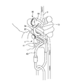
===降下器の構成===
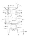
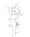
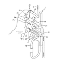
図1は、本発明に係る降下器の挿通穴にロープが挿通された状態を示す図、図2は、降下器の外観正面図、図3は、図2のA矢視図、図4は、図2のB矢視図、図5は、降下器のスライド部をスライド方向に引き出した状態を示す図、図6は、図5のC矢視図、である。
=== Configuration of the dropper ===
1 is a view showing a state in which a rope is inserted into an insertion hole of a lowering device according to the present invention, FIG. 2 is an external front view of the lowering device, FIG. 3 is a view as viewed from an arrow A in FIG. 2 is a view as seen from an arrow B in FIG. 2, FIG. 5 is a view showing a state in which the slide part of the lowering device is pulled out in the slide direction, and FIG.
本実施形態の降下器1は、降下する際に用いられるロープ3の一部を屈曲させた屈曲部分3aを、挿通させるための挿通穴12を有する本体10と、降下器1の使用状態におけるロープ3の方向と交差するスライド方向にスライド可能に設けられ、前記スライド方向の一方側にスライドされた状態にて前記挿通穴12に架け渡されて前記挿通穴を2つの穴部に区画し、前記スライド方向の他方側にスライドされた状態にて前記挿通穴12を1つの穴部とするためのスライド部20と、前記本体10の前記他方側に設けられ、前記スライド部20が前記一方側にスライドされた状態にて当該スライド部20の前記他方側へのスライドを規制するためのスライド規制機構30と、を有している。ここで、使用状態におけるロープ3の方向は、スライド部20のスライド方向に対し交差する方向となる。以下の説明においては、降下器1の使用状態、すなわち、降下器1を用いて吊り下げられたロープ3を伝って降下する際の状態にあわせて、スライド方向を左右方向ともいい、吊り下げられたロープ3の方向を上下方向ともいう。また、降下器1の使用状態にて使用者と対向する側を表面側とし、反対側を裏面側として示すこととする。
The lowering
本体10は、厚さ約15mmのほぼ直方体状のアルミニウムのブロック体であり、使用状態において上方側にほぼ長方形状の挿通穴12と、下方側に降下器1を使用する使用者の身体に固定されたカラビナ40が取り付けられる吊り下げ穴11とを有している。挿通穴12は、本体10の長手方向、すなわち上下方向に、挿通穴12の長手方向が沿わされて配置され、その短手方向の幅は、挿通されるロープ3の直径より十分に広く形成されている。このため、使用により消耗してロープ3の外径が大きくなったとしても、挿通穴12の内縁部分との間に生じる摩擦力が大きくなることはなく、ロープ3を容易に挿通させることが可能であり、また、引張力を緩めたロープ3を滑らかに滑らせることが可能である。吊り下げ穴11は、ほぼ三角形状をなし、前記挿通穴12と間隔を隔てて設けられて、三角形の1つの角部が下方側に向くように配置されている。
The
本体10の表面側には、挿通穴12の左右方向の両側部に位置させて、挿通穴12の上下方向におけるほぼ中央に表面から凹設された第1溝部15が設けられており、挿通穴12と吊り下げ穴11との間に位置させて表面から凹設された第2溝部16が設けられている。第1溝部15と第2溝部16とは、前記スライド方向に沿って平行をなし、本体の短手方向の全域に亘って設けられている。このとき、当然のことながら、第1溝部15は挿通穴12の部分には設けられていない。また、第1溝部15と第2溝部16とは、本体10の表面10aから約5mmの深さを有している。
On the surface side of the
また、本体10の左側部分において、第2溝部16から上方側が上下方向に細長く切り欠かれた切り欠き部13を有しているが、第1溝部15と第2溝部16との間の部位だけは、約5mmの厚さで左方向に突出された突部17が形成されている。
Further, the left side portion of the
さらに、本体10には、上部側の端部において、本体10の右側に1つと、下部側の端部において左右の両側に1つずつ、上下方向に沿って突出されたガイド部18が設けられている。このガイド部18は、ロープ3を本体10に、上下方向に沿って巻き付けた際に、巻き付けたロープ3がスライド方向に外れることを防止するために設けられている。
Further, the
スライド部20は、スライド方向の一方側としての右側にスライドされた際に、本体10の挿通穴12に架け渡されて挿通穴12を2つの穴部12a、12bに区画するための区画部21と、前記区画部21と間隔を隔てて平行に設けられたスライド補助部22と、前記区画部21とスライド補助部22とをスライド方向の他方側としての左側にて、それらの端部側を連結する連結部23と、区画部21、スライド補助部22、及び、連結部23と直角をなすように設けられ、スライド部20の右方向への移動を規制するストッパ24とを有している。
When the
スライド部20は、区画部21とスライド補助部22と連結部23とが平面視コ字状をなしており、本体10の表面側にてコ字の開放側が右側に位置するように配置され、本体10の表面10aと対向して左右方向にスライドするように設けられている。区画部21とスライド補助部22とは、連結部23より本体側に約5mm突出させて設けられている。そして、スライド部20を本体10に組み付けた際に、区画部21の突出部分の本体側の面21aが第1溝部15の底15aと接触し、スライド補助部22の突出部分の本体側の面22aが第2溝部16の底16aと接触するように構成されている。すなわち、第1溝部15と第2溝部16とは、スライド部20の上下方向への移動を規制すると共にスライド部20を左右方向に案内し、さらに、ロープ3の張力によりスライド部20が、左右方向に沿った軸周りに回転することも防止するように機能している。
The
区画部21は、スライド補助部22よりさらに厚く形成され、表面側の断面が円弧状をなしている。すなわち、区画部21の左右方向における中央の部位21bの表面は、挿通穴12が2つの穴部12a、12bに区画された際に、一方の穴部12aの裏面側から表面側に挿通され、他方の穴部12bを表面側から裏面側に抜けるロープ3が沿わされる部位であるため、ロープ3に引張力が作用した際にロープ3が中央の部位21bに密着して沿わされると共に、ロープ3の引張力が緩められた際には、ロープ3が滑らかに滑るように、半径10mm程度の円弧状に形成されている。また、区画部21の左側の部位21cは、後述するスライド規制機構30の操作の妨げにならないように、ロープ3が沿わされる中央の部位21bより薄く形成されている。
The
さらに、スライド部20の左上側の角部には、スライド部20のスライドを規制するスライド規制機構30の規制部31と係合するために僅かに凹設された凹部25が設けられている。
Further, a
スライド補助部22には左右方向に沿って、第2溝部16に螺合されるガイドピン29が貫通される長穴26が設けられている。ガイドピン29は、軸部29aと、軸部29aより拡径された円盤状の頭部29bとを有し、軸部29aの直径は長穴26の短手方向の幅より僅かに小さく、頭部29bの直径は長穴26の短手方向の幅より十分に大きく形成されている。また、ガイドピン29が本体10に螺合された状態にて、本体10の表面10aと頭部29bと距離がスライド補助部22の厚さより僅かに長くなるように軸部29aの長さが設定されている。頭部29bは前記長穴26の幅より十分大きく形成されているので、スライド部20が本体10から外れることを防止するとともに、スライド部がスライドする際のガイドとしても機能している。
The slide
ストッパ24は、区画部21、スライド補助部22、及び、連結部23の左側端にて裏面側に、本体10と直角をなすように延出されており、スライド部20が本体10に組み付けられた状態では、本体10の裏面より十分に突出するように形成されている。そして、ストッパ24は、スライド部20をスライドさせるために、使用者が本体10の裏面側に突出した部分に指先を掛ける際、指が回り込み易いように約6mmの厚さに形成されている。また、スライド部20の断面二次モーメントが大きくなるように、ストッパ24と、区画部21、スライド補助部22、及び、連結部23と、を直角に形成してスライド部20の高い剛性を確保している。
The
また、ストッパ24には、スライド部20を右側にスライドさせた際に、本体10に設けられ前述した突部17が嵌入される嵌入穴24aが設けられている。この嵌入穴24aは、突部17が嵌入された際に、嵌入穴24aと突部17との隙間が僅かに設けられておりスライド部20が滑らかにスライドするように構成されている。
Further, the
スライド部20は、スライド補助部22の長穴26に挿通されるガイドピン29により本体10に組み付けられる。このとき、スライド部20のがたつきを抑えると共に、スライド部20が滑らかにスライドするように、ガイドピン29の頭部29bとスライド補助部22との間には、ガイドピン29の頭部29b側に金属製のばね座金27が、スライド補助部22側に樹脂製の平座金28が、それぞれ介在されている。そして、スライド部20が、長穴26の右端がガイドピン29に当接されるように最も左側まで、ガイドピン29及び第1、第2溝部15,16に案内されてスライドされると、区画部21が挿通穴12の外側の領域に移動し、挿通穴12が1つの穴として表面側に現れる。一方、スライド部20がガイドピン29及び第1、第2溝部15,16に案内されて右方向にスライドされ、ストッパ24が本体10の側部に当接される最も右側にスライドされると、挿通穴12が区画部21により上下に2つの穴部12a、12bに区画されると共に、本体10の突部17がストッパ24の嵌入穴24aに嵌入される。この状態にて、ストッパ24は本体10の切り欠き部13に入り込み、ストッパ24の左側面24bと、本体10の第2溝部16より下方側の左側部10bとが、また、スライド部20の左上側の凹部25の左側面25aと、本体の切り欠き部13の側面13aとがそれぞれほぼ面一になる。すなわち、降下器1の左側部分は、使用者が降下器1を掴む部分なので、スライド部20を右側にスライドさせた際に、ストッパ24の左側面24bと、本体10の第2溝部16より下方側の左側部10bとがほぼ面一となることにより、使用者が降下器1を掴み易く、また、操作し易い構成としている。また、スライド部20の凹部25の左側面25aと、本体の切り欠き部13の側面13aとがほぼ面一になることにより、凹部25がスライド規制機構30の妨げとならない構成としている。
The
スライド規制機構30は、スライド部20の上側に位置させて、本体10の左側の切り欠き部13に設けられている。スライド規制機構30は、本体10の裏面側にネジにて固定され、断面がL字状をなすブラケット32と、本体10の表面10aと直交する面内にて回転する扇状の規制部31と、規制部31の回転軸となる軸ピン33とを有している。
The
ブラケット32は、本体10の裏面に接触する平面を有し、本体10にネジ止めされる板状の取り付け部32aと、取り付け部32aが曲げ起こされて形成され本体10の切り欠き部13の側面13aと対向する平面を構成する壁部32bとを有している。壁部32bは切り欠き部13の側面13aと間隔を隔てて配置され、壁部32bの本体10側の面が、本体10の第2溝部16より下方側の左側部10bとほぼ同じ位置になるように形成されている。壁部32bと本体10の切り欠き部13との間には軸ピン33が架け渡されており、軸ピン33は、規制部31が回動する軸部33aと、軸部33aより拡径された頭部33bとを有し、軸部33aの先端にはねじが設けられている。軸ピン33は、壁部32bの外側から壁部32bを貫通されて本体10の切り欠き部13に先端のねじが螺合されている。この軸ピン33を中心として規制部31が所定の角度の範囲で回動するように構成されている。このとき、軸ピン33の頭部33bと壁部32bとの間に介在されたばね座金35にてスライド規制機構30のがたつきが抑制されている。
The
扇状の規制部31には、操作する際に指が滑ることを防止するために、円弧部分31aがギア状に形成されている。そして、規制部31を上方向に回動させると、規制部31の上側の辺の部位31bが取り付け部32aの上端に当たり規制部31の回動が規制される。このとき、扇状の規制部31は下側の辺の部位31cが水平となると共に、区画部21より上方に位置する状態となり、スライド部20の規制が解除されてスライド可能となる。一方、規制部31を下方向に回動させると、規制部31の下側の辺の部位31cが取り付け部32aの下端に当たり規制部31の回動が規制される。このとき、扇状の規制部31はスライド部20の左上側に設けられた凹部25に入り込みスライド部20の左方向へのスライドを規制するように構成されている。
In the fan-shaped restricting
図7Aは、使用者が降下器を掴んだ状態を示す図、図7Bは、降下器のスライド部を左側にスライドさせた状態を示す図、図7Cは、降下器の挿通穴を通してロープの屈曲部を表面側に突出させた状態を示す図、図7Dは、スライド部を右側にスライドさせた状態を示す図、図7Eは、スライド規制機構によりスライド部のスライドを規制した状態を示す図、である。 FIG. 7A is a view showing a state where the user has grasped the lowering device, FIG. 7B is a view showing a state where the slide part of the lowering device is slid to the left side, and FIG. 7C is a view of bending the rope through the insertion hole of the lowering device FIG. 7D is a diagram illustrating a state in which the slide portion is slid to the right side, and FIG. 7E is a diagram illustrating a state in which the slide of the slide portion is regulated by the slide regulation mechanism. It is.
図示するように、本実施形態の降下器1を使用する際には、使用者は予め作業衣の腹部分に取り付けられたカラビナ40を降下器1の吊り下げ穴11に固定しておく。そして、本実施形態の場合には、使用者は左手にて、スライド規制機構30によりスライド部20のスライドが規制されている降下器1を掴む。このとき、左手の親指以外の指、すなわち、人差し指、中指、薬指、小指のうち3本程度を本体10の裏面側に突出している第1操作部としてのストッパ24にかけ、親指をスライド規制機構30の第2操作部としての規制部31にかけておく(図7A)。
As shown in the figure, when using the lowering
次に、使用者は、左手の親指にて規制部31を上方に押し回し、スライド規制機構30を解除し、本体10の裏面側にて指がかかっているストッパ24を左方向に移動させることによりスライド部20を左端までスライドさせる(図7B)。この操作により、区画されない挿通穴12が表面側に現れる。
Next, the user pushes the restricting
そして、使用者は、吊り下げられたロープ3の端部ではない部位を右手で掴み、ロープ3を2つ折り状に屈曲させて、降下器1の裏面側から屈曲部分3aを挿通させて表面10a側に突出させる(図7C)。このとき、表面10a側に突出された屈曲部分3aは裏面側に開放されたU字状をしている。
Then, the user grasps the portion that is not the end of the suspended
使用者は、U字状の屈曲部分3aの内側に区画部21が入り込むようにスライド部20を右方向に、ストッパ24が本体10に突き当たるまで移動させる(図7D)。このとき、区画部21が挿通穴12に架け渡されると共に、本体10の突部17が嵌入穴24aに嵌入される。
The user moves the
その後使用者は、左手の親指で規制部を下方向に押し回し、規制部31をスライド部20の凹部25に入り込ませ、スライド部20のスライドを規制する(図7E)。そして使用者は、ロープ3の、降下器1より下方側を右手で握り、身体に巻き付けるように腰に回し、握力によりロープ3に引張力を作用させる。ロープ3に引張力が作用すると、その引張力により区画部21は本体10側に押圧されることにより、本体10とスライド部20との間に摩擦力が生じスライド部20のスライドが抑制されるように作用する。また、ロープ3は本体10の裏面側にて挿通穴12の上下の縁部と、区画部21の表面側とに強く押圧されことにより、使用者はロープ3から吊り下げられた状態でも、滑り落ちることなく吊られた状態を維持することが可能である。このため、ロープ3が接触する降下器1の部位には、比較的大きくR面取りを施すことにより、ロープ3と降下器1との接触面積を大きくすると共に、ロープ3の損傷をも抑えている。
Thereafter, the user pushes the restricting portion downward with the thumb of the left hand, causes the restricting
また、吊り下げられた状態を維持する場合には、ロープ3の下端側を本体10に上下方向に沿って巻き付けても良い。図8は、降下器1にロープ3を巻き付けた状態を示す図である。図示するように、ロープ3の下端側を降下器1に巻き付けた際には、本体10上下端部に上下方向に沿って突出させたガイド部18によりロープ3の左右方向への移動が規制されるので、巻き付けたロープ3が外れることを防止することが可能である。本実施形態においては、ロープ3を本体10に対し上下方向に沿って巻き付けた例について説明したが、左右方向に巻き付けてもよい。この場合には、ガイド部を左右方向に突出させることが望ましい。また、本体10に巻き付けたロープ3を縛って本体10に固定することにより、吊り下げられた状態を、さらに安定させることが可能であり、右手を自由に動かすことも可能となる。
Moreover, when maintaining the state suspended, you may wind the lower end side of the
また、右手の操作によりロープ3の引張力を弱めることにより、降下器1とロープ3との摩擦力を低減させて、降下器1をロープ3に沿って滑らせて降下することが可能となる。このとき、ロープ3は、上下方向に配置された2つの穴部12a、12bに挿通されて下方に下ろされているだけであり、背景技術にて説明したカラビナのように鉛直方向を軸とするように巻き付けていない。このため、降下器1には回転方向の力が作用しないため、吊り下げられた使用者は安定した状態を保つことが可能であり、宙づり状態での作業も容易である。また、投下されたロープの下端部が回転しないので、地上での絡索によるヘリコプタの墜落を防止することが可能である。
Further, by weakening the pulling force of the
次に、使用者が地上に着地し、降下器1からロープ3を外す際には、左手の親指にて規制部31を上方向に押し回してスライド規制機構30を解除し(図7Dの状態)、ストッパ24を左方向に引くことにより挿通穴12が1つの穴部となりロープ3が裏面側に抜き取られる(図7Cの状態)。すなわち、背景技術にて示したカラビナを用いる場合にはロープ3を外す際に、一方の手で本体リング部を保持しつつ規制筒部を回転させたのち、ロープを十分に引き寄せて他方の手でロープをカラビナから抜き取らなければならないため、操作が煩雑であると共に手間がかかる。例えば、ロープ3がヘリコプタから吊り下げられている場合には、着地した際にヘリコプタがホバリングしている状態で、降下器1を外さなければならない。すなわち、ホバリングしているヘリコプタは位置が安定していないため、使用者はロープ3が外れるまではヘリコプタに引っ張られる畏れがある。このため降下器1を外す作業に手間取ると、使用者も移動しながらの作業を余儀なくされることとなりさらに手間取ることになる。また、ヘリコプタの移動によりロープ3に引張力が作用して、ロープ3を外すことがさらに困難になる畏れがある。しかしながら、本実施形態の降下器1によれば、スライド部を左側にスライドさせてしまえば、ロープに引張力が作用することにより自ずとロープ3は挿通穴12から抜けていくので、左手のみにより容易に外すことが可能である。特に、降下器1からロープ3を外す操作を、スライド部20をスライドさせることとしたので、本体10とスライド部20との間にて作用する摩擦力が小さくなるだけの簡単な操作により、ロープ3を降下器1から外すことが可能である。すなわち、着地によりロープ3の引張力を緩めるだけで、ロープ3を降下器1から容易に外すことが可能である。
Next, when the user lands on the ground and removes the
図9Aは、従来の降下器の他の例を示す図、図9Bは、従来の降下器からロープを外す様子を示す図である。図示するように、本実施形態のような1つの穴部にロープ3の屈曲部分3aを通し、屈曲部分3aに1つの穴部に架け渡される部材を架け渡して2つの穴部に区画する降下器としては、挿通穴51の左右方向のいずれかの縁部52に上下方向を軸として回動する回動部53を設けた、従来の降下器50がある。当然のことながら、この回動部53は、ロープ3が挿通される挿通穴51に架け渡される長さを有する必要がある。このため、ロープ3を外すために回動部53を回転させるには、ロープ3を緩めて回動部53の長さ分だけロープ3を表面側に引き出さなければならない。すなわち、ヘリコプタから吊り下げられた場合のように引張力が不意に作用するかもしれない状態にあっては、ロープ3を十分に緩めることは容易ではない。このため、本実施形態の降下器1のように降下器1からロープ3を外す際にはスライドさせる方法が特に優れた効果を奏する。
FIG. 9A is a diagram illustrating another example of a conventional lowering device, and FIG. 9B is a diagram illustrating a state where a rope is removed from the conventional lowering device. As shown in the drawing, the
すなわち、本実施形態の降下器によれば、本体10に設けられている挿通穴12はスライド部20を右方向にスライドさせると1つの挿通穴12を2つの穴部とし、左方向にスライドさせることにより、1つの挿通穴12に戻すことが可能である。このため、挿通穴12にロープ3の屈曲部分3aを挿通させて、スライド部20を右方向にスライドさせ、ロープ3の屈曲部分3aの円弧状となった内側に区画部21を通すだけで、挿通穴12が区画された2つの穴部12a、12bに1本のロープ3を通すことが可能である。また、降下器1からロープ3を外す際には、スライド部20を左方向にスライドさせるだけで1つの挿通穴12とすることができるため、簡単な操作により降下器1からロープ3を容易に、且つ短時間にて外すことが可能である。
That is, according to the lowering device of the present embodiment, the
また、スライド部20が右方側にスライドされた状態にて、スライド部20の左方向へのスライドを規制するためのスライド規制機構30が設けられているので、スライド部20が右方向にスライドされた状態、すなわち、区画された2つの穴部12a、12bにロープ3が通された状態を維持させることが可能である。このため、使用中にスライド部20が左方向にスライドして1つの挿通穴12となることを防止することが可能である。
Further, since the
また、挿通穴12が区画されて形成される2つの穴部12a、12bに挿通されたロープ3は、屈曲部分3aが本体10の表面側に残されて、ロープ3の2つの端部側は、それぞれ本体10の裏面側に位置することになる。このため、ロープ3に引張力が作用した際には、ロープ3の、表面側に位置する屈曲部分3aが、挿通穴12に架け渡されている区画部21を本体10方向に押圧するように作用する。このため、たとえスライド規制機構30が解除された後に、外部からスライド部20をスライド方向に移動させるような力が作用したとしても、ロープ3に引張力が作用している場合には、スライド部20の区画部21及びスライド補助部22と本体10の第1溝部15及び第2溝部16との接触部分の摩擦力が大きいためスライド部20がスライドすることを抑制させることが可能である。
Further, the
また、使用者は降下器1を片手で掴むだけで、親指以外の指にてストッパ24が操作可能となり、親指にて規制部31を操作することが可能となる。すなわち、降下器1にロープ3が挿通された状態にて、親指でスライド規制機構30を操作して、規制を解除し、そのまま親指以外の指でストッパ24を左方向に引いてスライド部20をスライドさせることが可能である。このため、片手の操作にて容易に、且つ短時間にてロープ3を外すことが可能な、操作性の良い降下器1を実現することが可能である。本実施形態においては、スライド部20を左方向にスライドさせ、スライド規制機構30を左側に設ける例について説明したが、スライド部20を右方向にスライドさせ、スライド規制機構30を右側に設けてもよい。この場合には、降下器1を右手にて操作することになり、左手が自由になるので、左利きの使用者に、より適した構造となる。また、この場合には、本体10の上部に設けられるガイド部18は左側に設けられることになる。
In addition, the user can operate the
また、スライド部20が右側にスライドされている際には、本体10からスライド方向に突出された突部17が嵌入穴24aに嵌入されるので、この突部17によりスライド部20が挿通穴12の挿通方向に移動されることを規制することが可能である。このため、より安定した状態にて本体10にロープ3を挿通させておくことが可能である。さらに、スライド部20の挿通方向への移動が規制されているので、誤ってロープ3の屈曲部分3aが裏面側に位置するようにロープ3を挿通させてしまった場合であっても、降下器1からロープ3が外れることを防止することが可能である。
Further, when the
降下器1を使用する際には、ロープ3の張力を調節しつつ降下器1を滑らせて降下する場合と、降下器1が滑らないようにしてロープ3の途中で吊り下げられた状態を維持する場合とがある。そして、吊り下げられた状態を維持する場合には、ロープ3を降下器1に巻き付けて降下器1が滑ることを防止することがある。このとき、本実施形態の降下器1のようにスライド方向と交差する方向、すなわち、ロープ3の引張方向にガイド部18が設けられていると、本体10に巻き付けたロープ3が降下器1から外れることを防止することが可能である。
When using the lowering
さらに、本体10の上方側には、スライド方向において規制部31と反対側にのみガイド部18が設けられているので、ガイド部18が規制部31の操作の障害となる畏れはない。また、下方側には、スライド方向における両側にガイド部18が設けられているので、スライド方向のいずれの側においても、巻き付けたロープ3が本体10から外れることを防止することが可能である。
Furthermore, since the
1 降下器、3 ロープ、3a 屈曲部分、
10 本体、10a 表面、10b 左側部、
11 吊り下げ穴、12 挿通穴、12a 穴部、12b 穴部、
13 切り欠き部、13a 側面、15 第1溝部、15a 第1溝部の底、
16 第2溝部、16a 第2溝部の底、
17 突部、18 ガイド部、20 スライド部、
21 区画部、21a 本体側の面、21b 中央の部位、21c 左側の部位、
22 スライド補助部、22a 本体側の面、23 連結部、
24 ストッパ、24a 嵌入穴、24b 左側面、
25 凹部、25a 左側面、26 長穴、27 ばね座金、28 平座金、
29 ガイドピン、29a 軸部、29b 頭部、30 スライド規制機構、
31 規制部、31a 円弧部分、31b 上側の辺の部位、31c 下側の辺の部位、
32 ブラケット、32a 取り付け部、32b 壁部、
33 軸ピン、33a 軸部、33b 頭部、35 ばね座金、
40 カラビナ、50 降下器、51 挿通穴、52 縁部、53 回動部、
60 カラビナ、61 本体リング部、62開閉部材、63規制筒部
1 dropper, 3 rope, 3a bent part,
10 body, 10a surface, 10b left side,
11 hanging hole, 12 insertion hole, 12a hole, 12b hole,
13 notch part, 13a side surface, 15 1st groove part, 15a bottom of 1st groove part,
16 second groove part, 16a bottom of the second groove part,
17 Projection, 18 Guide, 20 Slide,
21 partition part, 21a body side surface, 21b center part, 21c left part,
22 slide auxiliary part, 22a body side surface, 23 connecting part,
24 stopper, 24a insertion hole, 24b left side surface,
25 recess, 25a left side, 26 oblong hole, 27 spring washer, 28 flat washer,
29 guide pin, 29a shaft, 29b head, 30 slide regulating mechanism,
31 restriction part, 31a circular arc part, 31b upper side part, 31c lower side part,
32 bracket, 32a attachment part, 32b wall part,
33 shaft pin, 33a shaft, 33b head, 35 spring washer,
40 carabiner, 50 lowering device, 51 insertion hole, 52 edge, 53 rotating part,
60 carabiner, 61 body ring, 62 opening / closing member, 63 regulating cylinder
Claims (6)
前記ロープの一部が屈曲された屈曲部分を挿通させるための挿通穴を有する本体と、
使用状態における前記ロープの方向への移動が規制されるとともに前記ロープの方向と交差するスライド方向に前記本体により案内されてスライド可能に設けられ、前記スライド方向の一方側にスライドされた状態にて前記挿通穴に架け渡されて前記挿通穴を2つの穴部に区画し、前記スライド方向の他方側にスライドされた状態にて前記挿通穴を1つの穴部とするためのスライド部と、
前記本体の前記他方側に設けられ、前記スライド部が前記一方側にスライドされた状態にて当該スライド部の前記他方側へのスライドを規制するためのスライド規制機構と、
を有することを特徴とする降下器。 A descent device for descending from a high place using a rope,
A main body having an insertion hole for inserting a bent portion where a part of the rope is bent;
In a state in which movement in the direction of the rope in the use state is restricted and is slidably guided by the main body in a sliding direction intersecting the direction of the rope, and slid to one side of the sliding direction A slide portion for spanning the insertion hole to divide the insertion hole into two hole portions and sliding the insertion hole into one hole portion in a state of being slid to the other side in the sliding direction;
A slide regulating mechanism provided on the other side of the main body for regulating sliding of the slide portion to the other side in a state where the slide portion is slid to the one side;
A lowering device characterized by comprising:
前記スライド部は前記本体の表面側に設けられており、
前記挿通穴が区画されて形成される2つの穴部の一方には、前記ロープが裏面側から表面側に挿通され、他方には前記ロープが表面側から裏面側に挿通され、
前記ロープに引張力が作用した際に、前記スライド部が前記本体に押圧されることを特徴とする降下器。 The lowering device according to claim 1, wherein
The slide portion is provided on the surface side of the main body,
In one of the two holes formed by dividing the insertion hole, the rope is inserted from the back surface side to the front surface side, and in the other, the rope is inserted from the front surface side to the back surface side,
The lowering device according to claim 1, wherein when the tensile force acts on the rope, the slide portion is pressed against the main body.
前記スライド部は、前記スライド方向の他方側に、前記本体より裏面側に突出されて前記スライド部を前記他方側にスライドさせるための第1操作部を有し、
前記スライド規制機構は、前記スライド部のスライドを規制、または、規制を解除するための第2操作部を有し、
使用者が片手にて掴んだ際に、前記第1操作部に親指以外の指がかけられ、前記第2操作部に親指がかけられる位置に、前記第1操作部と前記第2操作部とが設けられていることを特徴とする降下器。 The lowering device according to claim 1 or 2,
The slide part has a first operation part on the other side in the slide direction, the first operation part protruding from the main body to the back side to slide the slide part to the other side.
The slide regulation mechanism has a second operation part for regulating the slide of the slide part or releasing the regulation,
When the user grasps with one hand, a finger other than a thumb is applied to the first operation unit, and the first operation unit, the second operation unit, A descent device characterized in that is provided.
前記本体は、前記スライド方向の他方側に突出された突部を有し、
前記スライド部は、当該スライド部が前記一方側にスライドされた際に前記突部が嵌入される嵌入穴を有することを特徴とする降下器。 The lowering device according to any one of claims 1 to 3,
The main body has a protrusion protruding to the other side in the sliding direction,
The slide part has a fitting hole into which the projecting part is fitted when the slide part is slid to the one side.
前記本体には、前記スライド方向と交差する交差方向の端部から当該交差方向に沿って突出され、前記ロープを前記本体に前記交差方向に沿って巻き付けた際に、巻き付けた前記ロープが前記本体から外れることを防止するためのガイド部が設けられていることを特徴とする降下器。 The lowering device according to any one of claims 1 to 4,
The main body protrudes along the crossing direction from the end in the crossing direction that intersects the sliding direction, and when the rope is wound around the main body along the crossing direction, the wound rope is the main body A descent device characterized by being provided with a guide portion for preventing it from coming off.
前記第2操作部は、使用状態において前記スライド部より上方側に設けられ、
上方側に設けられている前記ガイド部は、前記スライド方向において前記第2操作部と反対側に1つ設けられ、下方側に設けられている前記ガイド部は、前記スライド方向の両側に1つずつ設けられていることを特徴とする降下器。
The lowering device according to any one of claims 3 to 5,
The second operation part is provided above the slide part in a use state,
One guide portion provided on the upper side is provided on the opposite side to the second operation portion in the sliding direction, and one guide portion provided on the lower side is provided on both sides in the sliding direction. A dropper characterized by being provided one by one.
Priority Applications (1)
| Application Number | Priority Date | Filing Date | Title |
|---|---|---|---|
| JP2005172995A JP4247397B2 (en) | 2005-06-13 | 2005-06-13 | Dropper |
Applications Claiming Priority (1)
| Application Number | Priority Date | Filing Date | Title |
|---|---|---|---|
| JP2005172995A JP4247397B2 (en) | 2005-06-13 | 2005-06-13 | Dropper |
Publications (2)
| Publication Number | Publication Date |
|---|---|
| JP2006345948A JP2006345948A (en) | 2006-12-28 |
| JP4247397B2 true JP4247397B2 (en) | 2009-04-02 |
Family
ID=37642424
Family Applications (1)
| Application Number | Title | Priority Date | Filing Date |
|---|---|---|---|
| JP2005172995A Active JP4247397B2 (en) | 2005-06-13 | 2005-06-13 | Dropper |
Country Status (1)
| Country | Link |
|---|---|
| JP (1) | JP4247397B2 (en) |
Families Citing this family (4)
| Publication number | Priority date | Publication date | Assignee | Title |
|---|---|---|---|---|
| US8495800B2 (en) | 2006-12-05 | 2013-07-30 | Conterra, Inc. | Systems and methods for controlling rope |
| US7648126B2 (en) * | 2006-12-05 | 2010-01-19 | Conterra, Inc. | Systems and methods for controlling rope |
| KR101554814B1 (en) | 2014-02-21 | 2015-09-21 | 박병욱 | Apparatus for adjusting length of rope |
| GB2539942B (en) | 2015-07-01 | 2019-10-09 | Swisslogo Ag | A descender device |
-
2005
- 2005-06-13 JP JP2005172995A patent/JP4247397B2/en active Active
Also Published As
| Publication number | Publication date |
|---|---|
| JP2006345948A (en) | 2006-12-28 |
Similar Documents
| Publication | Publication Date | Title |
|---|---|---|
| JP4247397B2 (en) | Dropper | |
| US8793882B2 (en) | Safety cutter apparatus | |
| US10291002B2 (en) | Wire gripper | |
| US8261881B2 (en) | Multifunctional belay device for a rope | |
| WO2017119149A1 (en) | Wire gripper | |
| US20220361886A1 (en) | Clip applier | |
| JP2012120500A (en) | Reel lead | |
| JP2008114033A (en) | Umbrella handle with safety device against opening of umbrella due to unintentional touch | |
| KR20150144033A (en) | Electric-powered fishing reel | |
| KR200495986Y1 (en) | Safety hook for industrial | |
| JP6590677B2 (en) | Safety belt hook for work at height | |
| JP6631464B2 (en) | Inside door handle structure | |
| KR20090002311U (en) | Many Purposes Scissors | |
| JP6306490B2 (en) | Vehicle door handle device | |
| JP2009542336A (en) | Packet dispenser | |
| JP2013007220A (en) | Manipulator supporting structure for roll blind and roll blind | |
| JP2014217734A (en) | Roll paper holder and paper cutting method | |
| JP6188548B2 (en) | Load mounting device | |
| JP7453100B2 (en) | scissors | |
| JP3137536U (en) | Armor tool sheath | |
| TWI821395B (en) | Gripping device for indirect hot-line work | |
| JP2005034468A (en) | Peeler, and its main body part | |
| JP5792237B2 (en) | Insulation cover for distribution line | |
| JP2012249677A (en) | Cable cutting device | |
| JP4947748B1 (en) | Lid opening tool |
Legal Events
| Date | Code | Title | Description |
|---|---|---|---|
| A131 | Notification of reasons for refusal |
Free format text: JAPANESE INTERMEDIATE CODE: A131 Effective date: 20081007 |
|
| A521 | Written amendment |
Free format text: JAPANESE INTERMEDIATE CODE: A523 Effective date: 20081120 |
|
| TRDD | Decision of grant or rejection written | ||
| A01 | Written decision to grant a patent or to grant a registration (utility model) |
Free format text: JAPANESE INTERMEDIATE CODE: A01 Effective date: 20081216 |
|
| A01 | Written decision to grant a patent or to grant a registration (utility model) |
Free format text: JAPANESE INTERMEDIATE CODE: A01 |
|
| A61 | First payment of annual fees (during grant procedure) |
Free format text: JAPANESE INTERMEDIATE CODE: A61 Effective date: 20081217 |
|
| R150 | Certificate of patent or registration of utility model |
Free format text: JAPANESE INTERMEDIATE CODE: R150 |