JP4246169B2 - Wireless communication apparatus and wireless communication method - Google Patents
Wireless communication apparatus and wireless communication method Download PDFInfo
- Publication number
- JP4246169B2 JP4246169B2 JP2005067210A JP2005067210A JP4246169B2 JP 4246169 B2 JP4246169 B2 JP 4246169B2 JP 2005067210 A JP2005067210 A JP 2005067210A JP 2005067210 A JP2005067210 A JP 2005067210A JP 4246169 B2 JP4246169 B2 JP 4246169B2
- Authority
- JP
- Japan
- Prior art keywords
- vector
- signal
- transmission
- matrix
- transfer function
- Prior art date
- Legal status (The legal status is an assumption and is not a legal conclusion. Google has not performed a legal analysis and makes no representation as to the accuracy of the status listed.)
- Expired - Fee Related
Links
Images


Landscapes
- Radio Transmission System (AREA)
Description
本発明は、同一の周波数チャネルを用い、異なる複数の送信アンテナより独立なデータを送信し、複数の受信アンテナを用いて信号を受信し、各送受信アンテナ間の伝達関数行列をもとに受信局側でデータの復調を行うことにより無線通信を実現する高速無線アクセスシステム(または無線LANシステム)に係り、特に、2.4GHz帯または5GHz帯等を用いた高速無線アクセスシステムの伝送速度の高速化を行う無線通信装置および無線通信方法に関する。 The present invention uses the same frequency channel, transmits independent data from a plurality of different transmission antennas, receives signals using a plurality of reception antennas, and receives a reception station based on a transfer function matrix between the transmission and reception antennas. In particular, it relates to a high-speed wireless access system (or wireless LAN system) that realizes wireless communication by demodulating data, and in particular, increases the transmission speed of a high-speed wireless access system using the 2.4 GHz band or the 5 GHz band. The present invention relates to a wireless communication device and a wireless communication method.
近年、2.4GHz帯または5GHz帯を用いた高速無線アクセスシステムとして、IEEE802.11g規格、IEEE802.11a規格などの普及が目覚しい。これらのシステムでは、最大で54Mppsの伝送速度を実現しているが、無線LANの普及に伴い更なる伝送速度の高速化が求められている。 In recent years, the IEEE802.11g standard, the IEEE802.11a standard, and the like are remarkable as high-speed wireless access systems using the 2.4 GHz band or the 5 GHz band. In these systems, a transmission speed of 54 Mbps is realized at the maximum, but further increase in the transmission speed is required with the spread of wireless LAN.
そのための技術としては、MIMO(Multiple-Input Multiple-Output)技術が有力である。このMIMO技術とは、送信局側において複数の送信アンテナから同一チャネル上で異なる独立な信号を送信し、受信局側において同じく複数のアンテナを用いて信号を受信し、各送信アンテナ/受信アンテナ間の伝達関数行列を求め、この行列を用いて送信局側で各アンテナから送信した独立な信号を推定し、データを再生するものである。 As a technology for that purpose, MIMO (Multiple-Input Multiple-Output) technology is effective. This MIMO technology is such that different independent signals are transmitted on the same channel from a plurality of transmitting antennas on the transmitting station side, and signals are received using the same plurality of antennas on the receiving station side, between each transmitting antenna / receiving antenna. The transfer function matrix is obtained, the independent signal transmitted from each antenna is estimated on the transmitting station side using this matrix, and the data is reproduced.
ここで、N本の送信アンテナを用いてN系統の信号を送信し、M本のアンテナを用いて信号を受信する場合を考える。まず、送受信局の各アンテナ間にはM×N個の伝送のパスが存在し、第i送信アンテナから送信され、第j受信アンテナで受信される場合の伝達関数をhj,iとし、これを第(j,i)成分とするM行N列の行列をHと表記する。さらに、第i送信アンテナからの送信信号をtiとし、(t1,t2,t3,…,tN)を成分とする列ベクトルをT、第j受信アンテナでの受信信号をrjとし、(rl,r2,r3,…,rM)を成分とする列ベクトルをR、第j受信アンテナの熱雑音をnjとし(n1,n2,n3,…,nM)を成分とする列ベクトルをnと表記する。 Here, consider a case in which N signals are transmitted using N transmission antennas and signals are received using M antennas. First, there are M × N transmission paths between the antennas of the transmitting and receiving stations, and the transfer function when transmitted from the i-th transmitting antenna and received by the j-th receiving antenna is h j, i , A matrix of M rows and N columns where is a (j, i) -th component is denoted as H. Furthermore, a transmission signal from the i-th transmission antenna is denoted by t i , a column vector having components (t 1 , t 2 , t 3 ,..., T N ) as T, and a reception signal at the j-th reception antenna as r j , R is a column vector having (r 1 , r 2 , r 3 ,..., R M ) as components, and n j is the thermal noise of the j-th receiving antenna (n 1 , n 2 , n 3 ,. A column vector having M ) as a component is denoted by n.
この場合、以下の関係式が成り立つ。 In this case, the following relational expression holds.
![]()
![]()
したがって、受信局側で受信した信号Rを基に、送信信号Tを推定する技術が求められている。このMIMO技術の最も基本的なものとしては、一般にZF(Zero Forcing)法と呼ばれる方法が挙げられる(例えば非特許文献1参照)。 Therefore, there is a demand for a technique for estimating the transmission signal T based on the signal R received on the receiving station side. As the most basic one of the MIMO techniques, there is a method generally called a ZF (Zero Forcing) method (see, for example, Non-Patent Document 1).
ここでは、上記数式(1)に対し、伝達関数行列の逆行列H−1を求め、これを式の両辺の左から掛け合わせる処理を行う。この結果、以下の式が得られる。 Here, the inverse matrix H −1 of the transfer function matrix is obtained for the above formula (1), and this is multiplied from the left of both sides of the formula. As a result, the following expression is obtained.
![]()
![]()
つまり、各受信アンテナで受信した信号を合成し、所望の送信アンテナ以外からの信号による干渉を除去する処理を行うと、実際の送信信号ベクトルTに微小な熱雑音項H−1×nが加わった信号点が得られることになる。ここで、送信信号として、BPSK、QPSK、16QAM、64QAM等の多値変調を施した信号を用いる場合には、送信信号として取りうる信号点は不連続である。したがって、H−1×Rとユークリッド距離が最も近い点を送信コンスタレーション上で検索する硬判定処理を行い、真の送信信号を推定する。 That is, when the signals received by the respective receiving antennas are combined and processing for removing interference caused by signals from other than the desired transmitting antenna is performed, a minute thermal noise term H −1 × n is added to the actual transmitted signal vector T. Signal points are obtained. Here, when a signal subjected to multi-level modulation such as BPSK, QPSK, 16QAM, and 64QAM is used as a transmission signal, signal points that can be taken as the transmission signal are discontinuous. Therefore, a hard decision process is performed to search a point on the transmission constellation where H −1 × R is closest to the Euclidean distance to estimate a true transmission signal.
上述したZF法においては、熱雑音項H−1×nが十分に小さく、かつ送信アンテナ毎の成分が均等であると仮定できる場合には良好な特性が期待できる。しかし、一般には、この仮定は成り立たず、ある伝達関数行列に対して送信アンテナ毎の熱雑音H−1×nの絶対値の期待値は異なる。さらには、もし伝達関数行列Hが逆行列を持たない行列(ないしはその行列式が非常に小さい)の場合には、送信信号の推定が非常に不安定になる。このような状況においては、受信特性が大幅に劣化する可能性がある。このような問題点を解決するための方法として、最も特性的に優れた方法がMLD(Most Likelihood Detection)法と呼ばれる方式である(例えば非特許文献2参照)。 In the ZF method described above, good characteristics can be expected when the thermal noise term H −1 × n is sufficiently small and the components for each transmitting antenna can be assumed to be equal. However, in general, this assumption does not hold, and the expected value of the absolute value of the thermal noise H −1 × n for each transmission antenna differs for a certain transfer function matrix. Furthermore, if the transfer function matrix H is a matrix having no inverse matrix (or its determinant is very small), the estimation of the transmission signal becomes very unstable. In such a situation, reception characteristics may be significantly degraded. As a method for solving such a problem, a method having the most excellent characteristics is a method called an MLD (Most Likelihood Detection) method (see, for example, Non-Patent Document 2).
まず、各アンテナからの送信信号の変調方式が決まると、1つのアンテナから送信される信号が取り得る信号点の数(以降、Nmaxと呼ぶ)が決まる。N本のアンテナ全体で送信される信号ベクトルのバリエーションはNmax N種類となる。MLD法では、送信信号としてTxの取り得る全ての候補(全部でNmax N種)に対して、その信号が送信された場合の受信信号の予測を行い、それらの中で最も実際の受信信号に近いものを推定精度の最も高い信号点として選択する。つまり、Nmax N個中の第k番目の送信信号候補をT[k]で表したとすると、次の数式(3)で定義されるユークリッド距離Eを最小にするkの値を選択する。 First, when the modulation method of the transmission signal from each antenna is determined, the number of signal points that can be taken by a signal transmitted from one antenna (hereinafter referred to as N max ) is determined. There are N max N types of variations of signal vectors transmitted across the N antennas. In the MLD method, prediction of a reception signal when the signal is transmitted is performed on all candidates (total of N max and N types) that Tx can take as a transmission signal, and the most actual reception signal among them is predicted. Is selected as the signal point with the highest estimation accuracy. That is, if the kth transmission signal candidate in N max N is represented by T [k] , the value of k that minimizes the Euclidean distance E defined by the following equation (3) is selected.
なお、行列Mに対してMHは、行列Mのエルミート共役である行列を指す。以上の処理により、如何なる行列Hに対しても、安定した受信処理が可能であり、ZF法に対して特性が大幅に改善する。 Note that MH with respect to the matrix M indicates a matrix that is Hermitian conjugate of the matrix M. With the above processing, it is possible to perform stable reception processing for any matrix H, and the characteristics are greatly improved with respect to the ZF method.
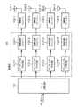
ここで、図7は、従来技術における送信局の構成を示すブロック図である。図において、100はデータ分割回路、101−1〜101−4はプリアンブル付与回路、102−1〜102−4は変調回路、103−1〜103−4は無線部、104−1〜104−4は送信アンテナ、105は変調部を示す。なお、一例として、送信局が4本の送信アンテナを用いて4系統のデータを送信する場合を例にとって説明する。 Here, FIG. 7 is a block diagram showing a configuration of a transmission station in the prior art. In the figure, 100 is a data division circuit, 101-1 to 101-4 are preamble assignment circuits, 102-1 to 102-4 are modulation circuits, 103-1 to 103-4 are radio units, 104-1 to 104-4. Denotes a transmission antenna, and 105 denotes a modulation unit. As an example, a case where the transmission station transmits four systems of data using four transmission antennas will be described as an example.
データが入力されると、データ分割回路100はデータを4系統に分離する。例えば、第1系統のデータはプリアンブル付与回路101−1に入力され、プリアンブル信号が付与された状態で変調回路(Ch1)102−1に入力される。変調回路(Ch1)102−1では所定の変調を実施し、変調された信号は無線部103−1にて無線周波数に変換され、送信アンテナ104−1より送信される。同様に、第2系統のデータは変調回路(Ch2)101−2〜送信アンテナ104−2、第3系統のデータは変調回路(Ch3)101−3〜送信アンテナ104−3、第4系統のデータは変調回路(Ch4)101−4〜送信アンテナ104−4を経由して、それぞれ個別に送信される。なお、後の説明のためにプリアンブル付与回路101−1〜101−4、変調回路102−1〜102−4を含む点線で囲った領域を変調部と呼ぶ。
When data is input, the
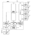
図8は、従来技術におけるMLD法を用いた受信局の構成を示すブロック図である。図において、111−1〜111−4は受信アンテナ、112−1〜112−4は無線部、113はチャネル推定回路、114は受信信号管理回路、115は伝達関数行列管理回路、116はレプリカ信号生成回路、117は送信信号生成回路、118は、幾何学的距離演算回路、119は選択回路、120はデータ合成回路、121は変調部を示す。なお、一例として、受信局が4本の受信アンテナを用いて4系統のデータを受信する場合を例にとって説明する。 FIG. 8 is a block diagram showing the configuration of a receiving station using the MLD method in the prior art. In the figure, 111-1 to 111-4 are receiving antennas, 112-1 to 112-4 are radio units, 113 is a channel estimation circuit, 114 is a received signal management circuit, 115 is a transfer function matrix management circuit, and 116 is a replica signal. A generation circuit, 117 is a transmission signal generation circuit, 118 is a geometric distance calculation circuit, 119 is a selection circuit, 120 is a data synthesis circuit, and 121 is a modulation unit. As an example, a case where the receiving station receives four systems of data using four receiving antennas will be described as an example.
第1の受信アンテナ111−1から第4の受信アンテナ111−4は、それぞれ個別に受信信号を受信する。無線部112−1〜112−4を経由して、受信した信号はチャネル推定回路113に入力される。送信側で付与して所定のプリアンブル信号の受信状況から、チャネル推定回路113にて各送信アンテナと受信アンテナ間の伝達関数を取得する。取得された各伝達関数の情報hj,iは、伝達関数行列管理回路115にて伝達関数行列Hとして管理される。
The first reception antenna 111-1 to the fourth reception antenna 111-4 individually receive the reception signals. The received signal is input to the
プリアンブル信号に後続するデータ信号は、1シンボル分ずつ受信信号管理回路114に入力される。受信信号管理回路114では、各アンテナの受信信号(r1,r2,r3,r4)を成分とした受信信号ベクトルRxとして一旦管理する。一方、送信信号生成回路117では、送信アンテナから出力され得る全ての信号パターンとして、Nmax N種類の送信信号の候補{T[k]}(1≦k≦Nmax N)を生成する。
The data signal following the preamble signal is input to the received
レプリカ信号生成回路116では、送信信号生成回路117から入力される信号T[k]と伝達関数行列管理回路115で管理された伝達関数行列Hとの積、H×T[k]を求め、幾何学的距離演算回路118にて、この結果と受信信号管理回路114で管理された受信信号ベクトルRxとのユークリッド距離を算出する。該ユークリッド距離演算処理は、全てのkの値に対して実施(合計Nmax N回)される。選択回路119では、これらの中でユークリッド距離が最短のものを選択し、最も推定精度の高い送信信号と判定する。
The replica
これらのデータは、複数シンボルに渡って連続的に処理されるが、一連のデータを受信後、データ合成回路120にてデータとして再構成されて出力される。なお、図7と同様、後の説明のためにチャネル推定回路113、受信信号管理回路114、伝達関数行列管理回路115、レプリカ信号生成回路116、送信信号生成回路117、幾何学的距離演算回路118、選択回路119を含む点線で囲った領域を復調部121と呼ぶ。
These data are continuously processed over a plurality of symbols, but after receiving a series of data, the
次に、図9は、従来技術におけるOFDM変調方式を用いた送信局の構成を示すブロック図である。図において、200はデータ分割回路、103−1〜103−4は無線部、104−1〜104−4は送信アンテナ、201−1〜201−Kは変調部、202−1〜202−3はIFFT回路、203−1〜203−3はGI挿入回路を示す。なお、一例として、送信局が4本の送信アンテナを用いて4系統のデータを送信する場合を例にとって説明する。 Next, FIG. 9 is a block diagram showing a configuration of a transmission station using the OFDM modulation scheme in the prior art. In the figure, 200 is a data division circuit, 103-1 to 103-4 are radio units, 104-1 to 104-4 are transmission antennas, 201-1 to 201-K are modulation units, and 202-1 to 202-3 are IFFT circuits 203-1 to 203-3 are GI insertion circuits. As an example, a case where the transmission station transmits four systems of data using four transmission antennas will be described as an example.
図7においては、シングルキャリアの場合を想定して説明を行ったため、変調部105は単一であったが、OFDM変調を行う場合には、サブキャリア毎に変調部105に相当するものを備えることになる。例えば、K本のサブキャリアを用いてデータ伝送を行う場合には、#1から#KまでのK面の変調部201−1〜201−Kを備えることになる。
In FIG. 7, since the description has been made assuming a single carrier, the
データが入力されると、データ分割回路200は、データを4×K系統に分離する。つまり、サブキャリア毎に4系統のデータ系列に分割する。これらは、サブキャリア毎に変調部201−1〜201−Kに入力され、図7に示した処理を各変調部201−1〜201−K内で行う。出力される変調信号は、信号系列毎にIFFT回路202−1〜202−4に入力される。ここでは、周波数軸上の信号を時間軸上の信号に変換する。変換された信号は、GI挿入回路203−1〜203−4にて1シンボル長の信号の一部(末尾)をコピーし、ガードインターバルとしてOFDMシンボルの先頭に付与する。付与された信号は、信号系列毎に無線部103−1〜103−4にて無線周波数に変換され、送信アンテナ104−1〜104−4より送信される。
When data is input, the
次に、図10は、従来技術におけるOFDM変調方式を用いた受信局の構成を示すブロック図である。図において、111−1〜111−4は受信アンテナ、112−1〜112−4は無線部、210−1〜210−4はGI除去回路、211−1〜211−4はFFT回路、212−1〜212−Kは復調部、213はデータ合成回路を示す。なお、一の例として、受信局が4本の受信アンテナを用いて4系統のデータを受信する場合を例にとって説明する。 Next, FIG. 10 is a block diagram showing a configuration of a receiving station using the OFDM modulation scheme in the prior art. In the figure, 111-1 to 111-4 are receiving antennas, 112-1 to 112-4 are radio units, 210-1 to 210-4 are GI removal circuits, 211-1 to 211-4 are FFT circuits, and 212- Reference numerals 1-212-K denote a demodulation unit, and 213 denotes a data synthesis circuit. As an example, a case where the receiving station receives four systems of data using four receiving antennas will be described as an example.
図8においては、シングルキャリアの場合を想定して説明を行ったため、復調部121は単一であったが、OFDM変調を行う場合には、サブキャリア毎に変調部121に相当するものを備えることになる。例えば、K本のサブキャリアを用いてデータ伝送を行う場合には、#1から♯KまでのK面の変調部212−1〜212−Kを備えることになる。
In FIG. 8, since the description has been made assuming a single carrier, the
第1の受信アンテナ111−1から第4の受信アンテナ111−4は、それぞれ個別に受信信号を受信する。無線部112−1〜112−4を経由して、受信した信号は、系列毎にGI除去回路210−1〜210−4に入力され、OFDMシンボル毎にガードインターバルが除去される。除去された信号は、FFT回路211−1〜211−4にて、時間軸上の信号から周波数軸上の信号に変換される。ここで、サブキャリア毎に分離された信号は、サブキャリア毎に復調部212−1〜212−Kにて、図8に示した処理が行われる。ここで、OFDMシンボル単位、かつサブキャリア単位で取得された送信信号の推定結果は、データ合成回路213にて合成され、データとして再構成されて出力される。なお、実際の回路においては、各サブキャリアにまたがって畳み込み符号化・ビタビ復号が実装されるなど、複数サブキャリアにまたがった誤り訂正処理などが行われる場合もあるが、基本的な構成に変わりはない。
The first reception antenna 111-1 to the fourth reception antenna 111-4 individually receive the reception signals. The received signal is input to the GI removal circuits 210-1 to 210-4 for each series via the radio units 112-1 to 112-4, and the guard interval is removed for each OFDM symbol. The removed signal is converted from a signal on the time axis to a signal on the frequency axis by the FFT circuits 211-1 to 211-4. Here, the signal separated for each subcarrier is subjected to the processing shown in FIG. 8 in demodulation sections 212-1 to 212-K for each subcarrier. Here, the estimation result of the transmission signal acquired in OFDM symbol units and subcarrier units is combined by the
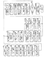
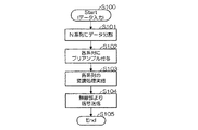
次に、図11は、従来技術における送信局の送信処理を示すフローチャートである。データが入力されると(S100)、送信局では、N系統のデータ系列に分割され(S101)、これらの信号には、それぞれプリアンブル信号が付与され(S102)、これに系列毎に個別に変調処理が行われる(S103)。変調された信号は、無線部にて無線周波数に変換されて送信される(S104)。 Next, FIG. 11 is a flowchart showing the transmission processing of the transmission station in the prior art. When data is input (S100), the transmitting station divides the data into N data series (S101), and these signals are respectively assigned preamble signals (S102), and are individually modulated for each series. Processing is performed (S103). The modulated signal is converted into a radio frequency by the radio unit and transmitted (S104).
次に、図12は、従来技術におけるMLD法を用いた受信局の受信処理を示すフローチャートである。受信局では、無線パケットを受信すると(S110)、プリアンブル信号を検出し(S111)、チャネル推定を実施する(S112)。ここでは、各送信アンテナおよび受信アンテナ間の伝達関数を全て取得する。プリアンブル信号に後続して受信される信号は、1シンボル毎に各受信アンテナでの受信信号rjを成分として持つ受信信号ベクトルRとして管理される(S113)。 Next, FIG. 12 is a flowchart showing reception processing of a receiving station using the MLD method in the prior art. When receiving the wireless packet (S110), the receiving station detects a preamble signal (S111) and performs channel estimation (S112). Here, all transfer functions between the transmission antennas and the reception antennas are acquired. A signal received subsequent to the preamble signal is managed as a received signal vector R having a received signal r j at each receiving antenna as a component for each symbol (S113).
これに対し、送信アンテナから出力され得る全ての信号パターンとして、Nmax N種類の送信信号の候補{T[k]}(1≦k≦Nmax N)を生成し、これと伝達関数行列Hとの積H×T[k]を計算し(S115)、受信信号Rとのユークリッド距離を計算する(S116)。この処理S114〜S116には、実際には、全体でNmax N回の処理を行うことを含めて記述した。つまり、処理S114〜S116をNmax N個並列的に処理したり、あるいはS114→S115→S116→S114→S115→S116→S114→S115→S116→…とNmax N回直列的に処理しても、あるいはその組み合わせであっても構わない。 On the other hand, N max N types of transmission signal candidates {T [k] } (1 ≦ k ≦ N max N ) are generated as all signal patterns that can be output from the transmission antenna, and the transfer function matrix H is generated. H × T [k] is calculated (S115), and the Euclidean distance from the received signal R is calculated (S116). In the processes S114 to S116, the description includes actually performing N max N times in total. That is, the processing S114 to S116 may be processed in N max N in parallel, or may be processed in N max N times serially as S114 → S115 → S116 → S114 → S115 → S116 → S114 → S115 → S116 →. Or a combination thereof.
いずれにせよ、算出されたNmax N個の送信信号ベクトル毎のユークリッド距離が得られたら、全体を比較して最小ユークリッド距離を与える送信信号ベクトルTbestを検索する(S117)。この結果をもって、該当するシンボルの各送信アンテナから送信された信号推定を確定させる(S118)。さらに、受信データが継続する場合には、処理S113に戻り、処理S113〜S119を繰り返す。受信データが終わった場合(S119)、一連の各系統の受信データを再構成し、送信側でのデータを再現してデータを出力する(S120)。なお、OFDM変調方式を用いる場合には、あるサブキャリアに着目すると、図11および図12に示した処理内容を行っていることになる。
上述したMLD法の最大の問題点は、ユークリッド距離を求める演算処理をNmax N回に渡って実施しなければならない点である。例えば、変調方式として64QAMを用いる場合、Nmax=64となる。この例を用いると、N=2の場合でユークリッド距離演算回数は642(=4096)回、N=3の場合で643(=262144)回、N=4の場合で644(=16777216)回と指数関数的に発散する。 The biggest problem of the MLD method described above is that the calculation process for obtaining the Euclidean distance must be performed N max N times. For example, when 64QAM is used as the modulation method, N max = 64. Using this example, the number of Euclidean distance calculations is 64 2 (= 4096) when N = 2 , 64 3 (= 262144) when N = 3, and 64 4 (= 166777216 when N = 4. ) Diversify exponentially with times.
これを回路として実現する際には、図12における処理S114〜S116を順次直列的に実施する方法と、並列的、つまり同時に処理する方法がある。しかし、直列的に行う場合には、1シンボルの送信データを確定するのに、Nmax N回のループ処理を行う必要があり、膨大な処理遅延がかかってしまう。一方、並列的に実施する場合でも、同様の回路をNmax N個も実装しなければならず、Nが3以上になると回路規模が爆発的に増大するため、LSIへの実装は全く不可能となる。その中間的な組み合わせも考えられるが、回路規模と演算時間との双方を両立することは困難である。全ての問題点は、演算の処理量がNmax Nに比例した値となることに起因し、この演算量を抑えることが課題となっている。 When this is realized as a circuit, there are a method of sequentially performing the processes S114 to S116 in FIG. 12 in series and a method of processing in parallel, that is, simultaneously. However, in the case of performing serially, it is necessary to perform N max N times of loop processing to determine one symbol of transmission data, which causes a huge processing delay. On the other hand, even when executed in parallel, N max N similar circuits must be mounted, and when N is 3 or more, the circuit scale increases explosively, so mounting on LSI is completely impossible. It becomes. An intermediate combination is also conceivable, but it is difficult to achieve both circuit scale and computation time. All the problems are caused by the fact that the processing amount of calculation becomes a value proportional to N max N , and it is a problem to suppress this calculation amount.
本発明は、このような事情を考慮してなされたものであり、その目的は、MIMO技術を用いた無線通信を行う際に、良好な特性を実現することができ、かつ現実的な回路規模および演算量にて容易に実現することができる無線通信装置および無線通信方法を提供することにある。 The present invention has been made in consideration of such circumstances, and an object of the present invention is to realize a good characteristic when performing wireless communication using MIMO technology, and to realize a realistic circuit scale. Another object of the present invention is to provide a wireless communication apparatus and a wireless communication method that can be easily realized with a calculation amount.
上述した課題を解決するために、M≧3となる整数M、N≧3となる整数N、1以上でかつM1+N2≦MおよびM2+N1≦Mおよび(N1+N2)=Nとなる整数N1、N2、M1、M2に対し、同一周波数チャネル上で複数の信号系列を空間上で多重化して送信するN本以上の送信アンテナを備えた送信局と、送信された無線信号を受信し、前記複数の信号系列に分離して受信処理を行うM本以上の受信アンテナを備えた受信局とにより構成され、前記送信局は、入力されたユーザデータをN系統に分割する手段と、前記のN系統に分割されたデータに個別の既知のパターンの信号を付与してN系統の第一の信号系列を生成する手段と、N本の前記送信アンテナを用いて同一周波数にて同時に前記信号系列を重畳して送信する手段とを備えた無線通信システムにおける前記受信局側で用いる無線通信装置であって、前記受信局は、M本の前記受信アンテナを用いて個別に無線信号を受信する受信手段と、受信信号に付与された既知のパターンの信号を参照信号として前記送信アンテナのうちの第iアンテナと前記受信アンテナのうちの第jアンテナとの間のM×N組の伝達関数hj,iを取得する第1の取得手段と、第i送信アンテナと第j受信アンテナとの間の伝達関数hj,iを第(j,i)成分とするM行N列の行列、すなわち伝達関数行列Hおよび第j受信アンテナの受信信号を第j成分とするM行の列ベクトルRおよびN個の成分を有するN行の列ベクトルTに対し、前記伝達関数行列Hと前記列ベクトルTとの積であるH・Tに対してR=H・TのTに対する解または近似解として1次推定列ベクトルTzfを取得する送信ベクトル第1次推定手段と、前記伝達関数行列Hの要素を元にM行(M1+M2)列の変換行列Zを生成する変換行列生成手段と、前記変換行列Zのエルミート共役の行列ZHに対して前記伝達関数行列Hの積、すなわち(M1+M2)行(N1+N2)列の行列ZH・Hを算出する算出手段と、該行列ZH・Hから1≦j≦M1かつ1≦i≦N1である第(j,i)成分より構成されるM1行N1列の第1部分行列H1と、M1+1≦j≦M1+M2かつN1+1≦i≦N1+N2である第(j,i)成分を抜き出して構成されるM2行N2列の第2部分行列H2とを取得する第2の取得手段と、M個の受信信号を成分とするM行の列ベクトルRと前記変換行列のエルミート共役の行列ZHとの積、すなわち(M1+M2)行の列ベクトルZH・Rを取得する第3の取得手段と、該列ベクトルZH・Rの第1成分から第M1成分までによって構成されるM1行の第1部分ベクトルをR1とし、かつ第M1+1成分から第M1+M2成分までを抜き出して構成されるM2行の第2部分ベクトルをR2としてR1およびR2を取得する第4の取得手段と、1系列当りの送信信号としてNmax種類(1<Nmax、Nmaxは整数)の信号点の選択肢の中からその全てないしはその一部として前記1次推定列ベクトルTzfの第k(1≦k≦N、kは整数)成分の近傍に位置するn[k]点(1≦n[k]≦Nmax、Nmaxは整数)の送信信号を第k成分の送信信号の候補として選択する選択手段と、第1から第N1番の各信号系列の送信信号を各成分として持つN1行の第1部分送信ベクトルをT1とした場合、該第1部分送信ベクトルT1の候補として、第1から第N1番の各信号系列の送信信号の各候補として選択された前記送信信号の候補をそれぞれN1個の各成分として持つ(n[1]×n[2]×…×n[N1])個のN1行の第1送信ベクトル候補群{T1 [k1]}(k1は識別番号)を取得する第5の取得手段と、第N1+1から第N番の各信号系列の送信信号を各成分として持つN2行の第2部分送信ベクトルをT2とした場合、該第2部分送信ベクトルT2の候補として、第N1+1から第N番の各信号系列の送信信号の各候補として選択された前記送信信号の候補をそれぞれN2個の各成分として持つ(n(N1+1)×n[N1+2]×…×n[N]個のN2行の第2送信ベクトル候補群{T2 [k2]}(k2は識別番号)を取得する第6の取得手段と、前記第1送信ベクトル候補群{T1 [k1]}のそれぞれに対し、R1とH1・T1 [k1]との幾何学的な距離を求める第1の幾何学的距離算出手段と、1≦K1<(n[1]×n[2]×…×n[N1])である整数K1に対し、前記第1送信ベクトル候補群の中で該幾何学的な距離がm1番目(1≦m1≦K1、m1は整数)に小さい候補をT’1 [m1]と表記した場合に前記第1送信ベクトル候補群の部分集合としてK1個のベクトルで構成される限定第1送信ベクトル候補群{T’1 [m1]}を取得する第7の取得手段と、前記第2送信ベクトル候補群{T2 [k2]}のそれぞれに対し、R2とH2・T2 [k2]との幾何学的な距離を求める第2の幾何学的距離算出手段と、1≦K2<(n[N1+1]×n[N1+2]×…×n[N])である整数K2に対し、前記第2送信ベクトル候補群の中で該幾何学的な距離がm2番目(1≦m2≦K2、m2は整数)に小さい候補をT’2 [m2]と表記した場合に前記第2送信ベクトル候補群の部分集合としてK2個のベクトルで構成される限定第2送信ベクトル候補群{T’2 [m2]}を取得する第8の取得手段と、前記限定第1送信ベクトル候補群{T’1 [m1]}の1つを第1から第N1番の各信号系列の送信信号を各成分として持ち、かつ前記限定第2送信ベクトル候補群{T’2 [m2]}の1つを第N1+1から第N番の各信号系列の送信信号を各成分として持つ合計K1×K2個のN行のベクトルを最終送信ベクトル候補群{Tfinal [k3]}(k3は識別番号)を取得する第9の取得手段と、前記最終送信ベクトル候補群{Tfinal [k3]}のそれぞれに対し、前記伝達関数行列Hおよび前記受信ベクトルRを用いてRとH・Tfinal [k3]との幾何学的な距離を求める第3の幾何学的距離算出手段と、該幾何学的な距離を最小とする送信ベクトルをTbestとして取得する第10の取得手段と、該送信ベクトルTbestの各成分を各信号系列の送信信号の推定値とし、これらを合成することにより前記送信局におけるユーザデータを再生する再生手段とを備えたことを特徴とする。
In order to solve the above-described problem, an integer M satisfying M ≧ 3, an integer N satisfying N ≧ 3, 1 or more, and M 1 + N 2 ≦ M and M 2 + N 1 ≦ M and (N 1 + N 2 ) = A transmission station including N or more transmission antennas that multiplex and transmit a plurality of signal sequences on the same frequency channel in space for integers N 1 , N 2 , M 1 , and M 2 that are N, and transmission And a receiving station having M or more receiving antennas for receiving the received radio signal and performing a receiving process by separating the signal into a plurality of signal sequences, and the transmitting station transmits the input user data to N systems Means for generating a first signal sequence of N systems by giving a signal of an individual known pattern to the data divided into the N systems, and using the N transmitting antennas Simultaneously transmit the signal sequence at the same frequency A wireless communication apparatus for use on the receiving station side in a wireless communication system comprising: a receiving means for individually receiving wireless signals using the M receiving antennas; and a received signal M × N sets of transfer functions h j, i between the i-th antenna of the transmitting antennas and the j-th antenna of the receiving antennas are obtained using a signal of a known pattern given to An M-row N-column matrix having the transfer function h j, i between the first acquisition means and the i-th transmit antenna and j-th receive antenna as the (j, i) component, that is, the transfer function matrix H and the H is a product of the transfer function matrix H and the column vector T with respect to an M-row column vector R and an N-row column vector T having N components, where the received signal of the j receiving antenna is the j-th component.・ R = H ・ T for T A transmission vector primary estimation means for obtaining a primary estimation column vector T zf as a solution or an approximate solution to T, and a transformation matrix Z of M rows (M 1 + M 2 ) columns based on the elements of the transfer function matrix H a transformation matrix generating means for generating for the product of the transfer function matrix H with respect to the matrix Z H Hermitian conjugate of the transform matrix Z, i.e. (M 1 + M 2) rows (N 1 + N 2) column matrix Z H · a First of M 1 rows and N 1 columns composed of calculating means for calculating H and the (j, i) -th component satisfying 1 ≦ j ≦ M 1 and 1 ≦ i ≦ N 1 from the matrix Z H · H a submatrix H 1, first of M 1 + 1 ≦ j ≦ M 1 +
本発明は、上記の発明において、前記受信局は、前記伝達関数行列Hの第i列を抜き出して得られるM行の列ベクトルhiを用いて前記伝達関数行列Hを(h[1],h[2],…,h[N])と表記し、さらに前記変換行列Zの第i列を抜き出して得られるM行の列ベクトルziを用いてM行(M1+M2)列の行列Zを(z[1],z[2],…,z[M1+M2])と表記した場合、M次元の複素空間において、N2個の列ベクトル群h[N1+1],h[N1+2],…,h[N1+N2]の全てに対して直交する空間に属し、かつそれぞれが互いに直交すると共に、絶対値の等しいM1個の列ベクトル群z[1],z[2],…,z[M1]を取得する第11の取得手段と、N1個の列ベクトル群h[1],h[2],…,h[N1]の全てに対して直交する空間に属し、かつそれぞれが互いに直交すると共に、絶対値の等しいM2個の列ベクトル群z[M1+1],z[M1+2],…,z[M1+M2]を取得する第12の取得手段とを備えたことを特徴とする。
The present invention, in the above invention, the receiving station, the transfer function matrix H using a column vector h i of M rows obtained by extracting the i-th column of the transfer function matrix H (h [1], h [2],..., h [N]), and M column (M 1 + M 2 ) columns using the M row column vector z i obtained by extracting the i th column of the transformation matrix Z. When the matrix Z is expressed as (z [1], z [2],..., Z [M 1 + M 2 ]), in an M-dimensional complex space, N 2 column vector groups h [N 1 +1], A group of M 1 column vectors z [1] belonging to a space orthogonal to all of h [N 1 +2],..., h [N 1 + N 2 ] and orthogonal to each other and having the same absolute value. , z [2], ..., z and eleventh obtaining means for obtaining [M 1], N 1 single column vector group h [1], h [ ], ..., h [belong to the space orthogonal to all the N 1], and with each perpendicular to each other, equal M 2 pieces of column vector group z in absolute value [
本発明は、上記の発明において、前記受信局は、前記伝達関数行列Hを元に受信される信号系列毎の信号対雑音比または信号対干渉雑音比を推定する推定手段を備え、さらに、前記第1の取得手段は、前記推定手段で取得した受信される信号系列毎の信号対雑音比または信号対干渉雑音比に応じて前記伝達関数における送信アンテナ番号の番号付け順序を変更する第1のアンテナ番号変換手段を備え、さらに、前記第10の取得手段は、取得される送信ベクトルTbestの送信アンテナ番号の番号付けを、第1のアンテナ番号変換手段にて実施した入れ替え処理の逆処理により、元々のアンテナ番号に戻す第2のアンテナ番号変換手段を備えたことを特徴とする。 According to the present invention, in the above invention, the receiving station includes an estimation unit that estimates a signal-to-noise ratio or a signal-to-interference noise ratio for each signal sequence received based on the transfer function matrix H, and A first acquisition unit configured to change a numbering order of transmission antenna numbers in the transfer function according to a signal-to-noise ratio or a signal-to-interference noise ratio for each received signal sequence acquired by the estimation unit; An antenna number conversion means; and the tenth acquisition means performs the numbering of the transmission antenna number of the acquired transmission vector T best by the reverse process of the replacement process performed by the first antenna number conversion means. The second antenna number conversion means for returning to the original antenna number is provided.
本発明は、上記の発明において、前記受信局は、前記伝達関数行列Hを元に受信される信号系列毎の総受信電力、信号対雑音比または信号対干渉雑音比のいずれかを推定する推定手段と、前記n[1],n[2],n[3],…,n[N]の値を信号系列毎の総受信電力または信号対雑音比または信号対干渉雑音比の推定値に応じて決定する決定手段とを備えたことを特徴とする。 According to the present invention, in the above invention, the receiving station estimates the total received power, signal-to-noise ratio, or signal-to-interference noise ratio for each signal sequence received based on the transfer function matrix H. , And n [1], n [2], n [3],..., N [N] as total received power or signal-to-noise ratio or estimated signal-to-interference noise ratio for each signal sequence. It is characterized by comprising a determination means for determining accordingly.
本発明は、上記の発明において、前記第1の幾何学的距離算出手段は、前記幾何学的な距離としてユークリッド距離を用いることを特徴とする。 The present invention is characterized in that, in the above invention, the first geometric distance calculation means uses a Euclidean distance as the geometric distance.
本発明は、上記の発明において、前記第1の幾何学的距離算出手段は、幾何学的な距離として、各成分の実部の絶対値および虚数部の絶対値の和を全ての信号系列に対して加算した値を用いることを特徴とする。 According to the present invention, in the above invention, the first geometric distance calculation means uses the sum of the absolute value of the real part and the absolute value of the imaginary part for all signal sequences as the geometric distance. It is characterized by using the added value.
本発明は、上記の発明において、前記送信ベクトル第1次推定手段は、前記伝達関数行列Hと前記列ベクトルTとの積であるH・Tに対してR=H・TのTに対する解または近似解として前記1次推定列ベクトルTzfを取得するために、前記第1部分行列H1および第1部分ベクトルR1および第1送信ベクトルT1に対するR1=H1・T1の解または近似解として前記1次推定列ベクトルTzfの第1から第N1成分を取得する第16の取得手段と、前記第2部分行列H2および第2部分ベクトルR2および第2送信ベクトルT2に対するR2=H2・T2の解または近似解として前記1次推定列ベクトルTzfの第N1+1から第N成分を取得する第17の取得手段とを備えたことを特徴とする。 According to the present invention, in the above invention, the transmission vector primary estimation means is a solution for T of R = H · T with respect to H · T that is a product of the transfer function matrix H and the column vector T or In order to obtain the primary estimated column vector T zf as an approximate solution, the solution of R 1 = H 1 · T 1 for the first partial matrix H 1, the first partial vector R 1 and the first transmission vector T 1 or Sixteenth obtaining means for obtaining the first to N 1st components of the primary estimated column vector T zf as an approximate solution, the second partial matrix H 2, the second partial vector R 2, and the second transmission vector T 2 And 17th acquisition means for acquiring the Nth component from the N 1 +1 of the primary estimated sequence vector T zf as a solution or approximate solution of R 2 = H 2 · T 2 with respect to.
本発明は、上記の発明において、前記送信ベクトル第1次推定手段は、前記伝達関数行列Hと前記列ベクトルTとの積であるH・Tに対してR=H・TのTに対する解または近似解として前記1次推定列ベクトルTzfを取得するために、前記伝達関数行列Hの逆行列H−1を前記列ベクトルRに作用させたベクトル積、すなわちH−1・Rにより取得する第18の取得手段を備えたことを特徴とする。 According to the present invention, in the above invention, the transmission vector primary estimation means is a solution for T of R = H · T with respect to H · T that is a product of the transfer function matrix H and the column vector T or In order to obtain the primary estimated column vector T zf as an approximate solution, the inverse matrix H −1 of the transfer function matrix H is obtained by a vector product obtained by acting on the column vector R, that is, H −1 · R. Eighteen acquisition means are provided.
本発明は、上記の発明において、前記送信ベクトル第1次推定手段は、前記伝達関数行列Hと前記列ベクトルTとの積であるH・Tに対してR=H・TのTに対する解または近似解として前記1次推定列ベクトルTzfを取得するために、前記伝達関数行列Hのエルミート共役行列HHおよび該伝達関数行列Hのベクトル積に対する逆行列、すなわち(HH・H)−1と、前記行列HHおよび前記列ベクトルRのベクトル積、すなわち(HH・H)−1・HH・Rにより取得する第19の取得手段を備えたことを特徴とする。 According to the present invention, in the above invention, the transmission vector primary estimation means is a solution for T of R = H · T with respect to H · T that is a product of the transfer function matrix H and the column vector T or In order to obtain the primary estimated column vector T zf as an approximate solution, the Hermitian conjugate matrix H H of the transfer function matrix H and the inverse matrix of the vector product of the transfer function matrix H, that is, (H H · H) −1 And a vector product of the matrix H H and the column vector R, ie, (H H · H) −1 · H H · R, obtaining nineteenth acquisition means.
本発明は、上記の発明において、前記N系統の既知のパターンの信号の第i信号系列における第ks(ksは1以上の整数)シンボルの送信信号をP(i,ks)および第j受信アンテナで受信される第ksシンボルの受信信号をr(j,ks)とし、かつP(i,ks)を第i成分として持つN行の列ベクトルをP(ks)、r(j、ks)を第j成分として持つM行の列ベクトルをr(ks)と表現した場合において、前記送信ベクトル第1次推定手段は、前記既知のパターンの信号を受信した際に、前記既知のパターンの信号の領域においてM行N列の行列Fに関して、ベクトルF×r(ks)−P(ks)および該ベクトルのエルミート共役のベクトル(F×r(ks)−P(ks))Hのベクトル積、すなわち(F×r(ks)−P(ks))H×(F×r(ks)−P(ks))で与えられる物理量を最小とするように前記行列Fを算出する算出手段と、該行列Fと前記列ベクトルRのベクトル積、すなわちF・Rにより前記1次推定列ベクトルTzfを取得する第20の取得手段とを備えたことを特徴とする。 According to the present invention, in the above invention, a transmission signal of ks (k is an integer of 1 or more) symbols in the i-th signal sequence of the N patterns of known patterns is represented by P (i, ks) and the j-th reception antenna. The received signal of the k-th symbol received in step r is r (j, ks), and the column vector of N rows having P (i, ks) as the i-th component is P (ks) and r (j, ks). In the case where the column vector of M rows as the j-th component is expressed as r (ks), the transmission vector primary estimation unit receives the signal of the known pattern when receiving the signal of the known pattern. A vector product of a vector F × r (ks) −P (ks) and a Hermitian conjugate of the vector (F × r (ks) −P (ks)) H for a matrix F of M rows and N columns in the region, (F × r (ks) −P (Ks)) A calculation means for calculating the matrix F so as to minimize a physical quantity given by H × (F × r (ks) −P (ks)), and a vector product of the matrix F and the column vector R That is, a 20th acquisition means for acquiring the primary estimated sequence vector T zf by F · R is provided.
本発明は、上記の発明において、前記送信局および受信局は、直交周波数分割多重変調方式を用いて無線通信を行い、サブキャリア毎に分離後の受信信号に対して、個別に請求項1ないし請求項10に記載の処理を実施することを特徴とする。
According to the present invention, in the above invention, the transmitting station and the receiving station perform wireless communication using an orthogonal frequency division multiplexing modulation system, and individually receive signals separated for each subcarrier. The processing according to
上述した課題を解決するために、本発明は、M≧3となる整数M、N≧3となる整数N、1以上でかつM1+N2≦MおよびM2+N1≦Mおよび(N1+N2)=Nとなる整数N1、N2、M1、M2に対し、同一周波数チャネル上で複数の信号系列を空間上で多重化して送信するN本以上の送信アンテナを備えた送信局と、送信された無線信号を受信し、前記複数の信号系列に分離して受信処理を行うM本以上の受信アンテナを備えた受信局とにより構成され、前記送信局は、入力されたユーザデータをN系統に分割するステップと、前記のN系統に分割されたデータに個別の既知のパターンの信号を付与してN系統の第一の信号系列を生成するステップと、N本の前記送信アンテナを用いて同一周波数にて同時に前記信号系列を重畳して送信するステップとを実施する無線通信システムにおける前記受信局側で用いる無線通信方法であって、前記受信局は、M本の前記受信アンテナを用いて個別に無線信号を受信するステップと、受信信号に付与された既知のパターンの信号を参照信号として前記送信アンテナのうちの第iアンテナと前記受信アンテナのうちの第jアンテナとの間のM×N組の伝達関数hj,iを取得するステップと、第i送信アンテナと第j受信アンテナとの間の伝達関数hj,iを第(j,i)成分とするM行N列の行列、すなわち伝達関数行列Hおよび第j受信アンテナの受信信号を第j成分とするM行の列ベクトルRおよびN個の成分を有するN行の列ベクトルTに対し、前記伝達関数行列Hと前記列ベクトルTとの積であるH・Tに対してR=H・TのTに対する解または近似解として1次推定列ベクトルTzfを取得する送信ベクトル第1次推定ステップと、前記伝達関数行列Hの要素を元にM行(M1+M2)列の変換行列Zを生成するステップと、前記変換行列Zのエルミート共役の行列ZHに対して前記伝達関数行列Hの積、すなわち(M1+M2)行(N1+N2)列の行列ZH・Hを算出するステップと、該行列ZH・Hから1≦j≦M1かつ1≦i≦N1である第(j,i)成分より構成されるM1行N1列の第1部分行列H1と、M1+1≦j≦M1+M2かつN1+1≦i≦N1+N2である第(j,i)成分を抜き出して構成されるM2行N2列の第2部分行列H2とを取得するステップと、M個の受信信号を成分とするM行の列ベクトルRと前記変換行列のエルミート共役の行列ZHとの積、すなわち(M1+M2)行の列ベクトルZH・Rを取得するステップと、該列ベクトルZH・Rの第1成分から第M1成分までによって構成されるM1行の第1部分ベクトルをR1とし、かつ第M1+1成分から第M1+M2成分までを抜き出して構成されるM2行の第2部分ベクトルをR2としてR1およびR2を取得するステップと、1系列当りの送信信号としてNmax種類(1<Nmax、Nmaxは整数)の信号点の選択肢の中からその全てないしはその一部として前記1次推定列ベクトルTzfの第k(1≦k≦N、kは整数)成分の近傍に位置するn[k]点(1≦n[k]≦Nmax、Nmaxは整数)の送信信号を第k成分の送信信号の候補として選択するステップと、第1から第N1番の各信号系列の送信信号を各成分として持つN1行の第1部分送信ベクトルをT1とした場合、該第1部分送信ベクトルT1の候補として、第1から第N1番の各信号系列の送信信号の各候補として選択された前記送信信号の候補をそれぞれN1個の各成分として持つ(n[1]×n[2]×…×n[N1])個のN1行の第1送信ベクトル候補群{T1 [k1]}(k1は識別番号)を取得するステップと、第N1+1から第N番の各信号系列の送信信号を各成分として持つN2行の第2部分送信ベクトルをT2とした場合、該第2部分送信ベクトルT2の候補として、第N1+1から第N番の各信号系列の送信信号の各候補として選択された前記送信信号の候補をそれぞれN2個の各成分として持つ(n(N1+1)×n[N1+2]×…×n[N]個のN2行の第2送信ベクトル候補群{T2 [k2]}(k2は識別番号)を取得するステップと、前記第1送信ベクトル候補群{T1 [k1]}のそれぞれに対し、R1とH1・T1 [k1]との幾何学的な距離を求めるステップと、1≦K1<(n[1]×n[2]×…×n[N1])である整数K1に対し、前記第1送信ベクトル候補群の中で該幾何学的な距離がm1番目(1≦m1≦K1、m1は整数)に小さい候補をT’1 [m1]と表記した場合に前記第1送信ベクトル候補群の部分集合としてK1個のベクトルで構成される限定第1送信ベクトル候補群{T’1 [m1]}を取得するステップと、前記第2送信ベクトル候補群{T2 [k2]}のそれぞれに対し、R2とH2・T2 [k2]との幾何学的な距離を求めるステップと、1≦K2<(n[N1+1]×n[N1+2]×…×n[N])である整数K2に対し、前記第2送信ベクトル候補群の中で該幾何学的な距離がm2番目(1≦m2≦K2、m2は整数)に小さい候補をT’2 [m2]と表記した場合に前記第2送信ベクトル候補群の部分集合としてK2個のベクトルで構成される限定第2送信ベクトル候補群{T’2 [m2]}を取得するステップと、前記限定第1送信ベクトル候補群{T’1 [m1]}の1つを第1から第N1番の各信号系列の送信信号を各成分として持ち、かつ前記限定第2送信ベクトル候補群{T’2 [m2]}の1つを第N1+1から第N番の各信号系列の送信信号を各成分として持つ合計K1×K2個のN行のベクトルを最終送信ベクトル候補群{Tfinal [k3]}(k3は識別番号)を取得するステップと、前記最終送信ベクトル候補群{Tfinal [k3]}のそれぞれに対し、前記伝達関数行列Hおよび前記受信ベクトルRを用いてRとH・Tfinal [k3]との幾何学的な距離を求めるステップと、該幾何学的な距離を最小とする送信ベクトルをTbestとして取得するステップと、該送信ベクトルTbestの各成分を各信号系列の送信信号の推定値とし、これらを合成することにより前記送信局におけるユーザデータを再生するステップとを有することを特徴とする。 In order to solve the above-described problems, the present invention provides an integer M in which M ≧ 3, an integer N in which N ≧ 3, 1 or more, and M 1 + N 2 ≦ M and M 2 + N 1 ≦ M and (N 1 + N 2 ) = N transmissions provided with N or more transmission antennas that multiplex and transmit a plurality of signal sequences in space on the same frequency channel for integers N 1 , N 2 , M 1 , M 2 where N And a receiving station having M or more receiving antennas that receive a transmitted radio signal and perform reception processing by separating the plurality of signal sequences, and the transmitting station is an input user Dividing the data into N systems, generating a first signal sequence of N systems by adding individual known pattern signals to the data divided into the N systems, and transmitting the N transmissions Simultaneously using the antenna at the same frequency A wireless communication method used on the receiving station side in a wireless communication system that performs a process of superimposing and transmitting a sequence, wherein the receiving station individually receives wireless signals using M receiving antennas M × N sets of transfer functions h j between the i-th antenna of the transmitting antennas and the j-th antenna of the receiving antennas using a step and a signal of a known pattern added to the received signal as a reference signal , I , and a matrix of M rows and N columns with the transfer function h j, i between the i th transmit antenna and the j th receive antenna as the (j, i) component, ie, the transfer function matrix H and The product of the transfer function matrix H and the column vector T with respect to an M-row column vector R and an N-row column vector T having N components, where the received signal of the j-th receive antenna is the j-th component. HT On the other hand, a transmission vector primary estimation step for obtaining a primary estimation column vector T zf as a solution or approximate solution for T of R = H · T, and M rows (M 1 + M based on the elements of the transfer function matrix H) 2 ) A step of generating a transformation matrix Z having columns, and a product of the transfer function matrix H with respect to the Hermitian conjugate matrix Z H of the transformation matrix Z, that is, (M 1 + M 2 ) rows (N 1 + N 2 ) columns the matrix Z calculating a H · H, the matrix Z H · H from 1 ≦ j ≦ M 1 and 1 ≦ i ≦ N 1 a is a (j, i) composed of the component M 1 row N 1 The first submatrix H 1 of the column and M 2 rows N configured by extracting the (j, i) component that satisfies M 1 + 1 ≦ j ≦ M 1 + M 2 and N 1 + 1 ≦ i ≦ N 1 + N 2 A step of obtaining a second partial matrix H 2 having two columns, and M rows having M received signals as components Obtaining a product, i.e. a (M 1 + M 2) column vectors Z H · R rows of the matrix Z H of Hermitian conjugate column vector R and the transformation matrix, a first said column vector Z H · R a first portion vector of M 1 line containing component by up to the M 1 component and R 1, and the M 1 +1 components the M 1 + M 2 second M 2 rows constituted by extracting until the components R 1 and R 2 are obtained by sub-vector R 2 , and all or all of N max types (1 <N max , where N max is an integer) of signal point choices as transmission signals per sequence As a part, n [k] points (1 ≦ n [k] ≦ N max , N max ) located near the k-th (1 ≦ k ≦ N, k is an integer) component of the primary estimated sequence vector T zf are (Integer) transmission signal and kth component transmission signal Selecting as a candidate, when the first part transmission vector of N 1 rows, with a transmission signal of each signal sequence of the N 1 th from the first as each component was T 1, the first portion transmitted vector T as one of the candidates, the first having a respective component candidates of one n wherein each of the transmission signal is selected as the candidate of the transmission signal of each signal sequence of the n 1 th (n [1] × n [ 2 ] ×... × n [N 1 ]) N 1- row first transmission vector candidate group {T 1 [k1] } (k1 is an identification number), N 1 +1 to N-th When the second partial transmission vector of N 2 rows having the transmission signal of each signal series as each component is T 2 , N 1 +1 to N-th signals are candidates for the second partial transmission vector T 2. Each of the transmission signal candidates selected as each of the transmission signal candidates of the sequence N having as two of the components (n (N 1 +1) × n [N 1 +2] × ... × n [N] number of N 2, line 2 transmission vector candidates of {T 2 [k2]} ( k2 Is an identification number) and a step of obtaining a geometric distance between R 1 and H 1 · T 1 [k1] for each of the first transmission vector candidate groups {T 1 [k1] }. And an integer K 1 where 1 ≦ K 1 <(n [1] × n [2] ×... × n [N 1 ]), the geometric distance in the first transmission vector candidate group. Is a m1th (1 ≦ m1 ≦ K 1 , m1 is an integer) candidate T ′ 1 [m1], and is composed of K 1 vectors as a subset of the first transmission vector candidate group. Obtaining a limited first transmission vector candidate group {T ′ 1 [m1] }; and the second transmission vector candidate group {T 2 For each [k2] }, the step of determining the geometric distance between R 2 and H 2 · T 2 [k2] , 1 ≦ K 2 <(n [N 1 +1] × n [N 1 +2] to] × ... × n integer K 2 is [n]), the second What histological distance m2 th該幾in transmit vector candidates (1 ≦ m2 ≦ K 2, m2 is small integer) When a candidate is expressed as T ′ 2 [m2] , a limited second transmission vector candidate group {T ′ 2 [m2] } composed of K 2 vectors is obtained as a subset of the second transmission vector candidate group. And having one of the limited first transmission vector candidate group {T ′ 1 [m1] } as a transmission signal of each of the first to N 1st signal sequences, and the limited second transmission One of the vector candidate groups {T ′ 2 [m2] } is transmitted as the transmission signal of each of the N 1 +1 to N-th signal sequences. A final transmission vector candidate group {T final [k3] } (k3 is an identification number) with a total of K 1 × K 2 N rows of vectors having as components, and the final transmission vector candidate group {T for each final [k3] }, using the transfer function matrix H and the received vector R to determine a geometric distance between R and HT final [k3], and the geometric distance obtaining a transmit vector to minimize a T best, and the respective components of the transmission vector T best the estimate of the transmitted signal of each signal sequence, to reproduce the user data in the transmission station by combining these And a step.
本発明は、上記の発明において、前記伝達関数行列Hの第i列を抜き出して得られるM行の列ベクトルhiを用いて前記伝達関数行列Hを(h[1],h[2],…,h[N])と表記し、さらに前記変換行列Zの第i列を抜き出して得られるM行の列ベクトルziを用いてM行(M1+M2)列の行列Zを(z[1],z[2],…,z[M1+M2])と表記した場合、M次元の複素空間において、N2個の列ベクトル群h[N1+1],h[N1+2],…,h[N1+N2]の全てに対して直交する空間に属し、かつそれぞれが互いに直交すると共に、絶対値の等しいM1個の列ベクトル群z[1],z[2],…,z[M1]を取得するステップと、N1個の列ベクトル群h[1],h[2],…,h[N1]の全てに対して直交する空間に属し、かつそれぞれが互いに直交すると共に、絶対値の等しいM2個の列ベクトル群z[M1+1],z[M1+2],…,z[M1+M2]を取得するステップとをさらに有することを特徴とする。 The present invention, in the above invention, the transfer function matrix H using a column vector h i of M rows obtained by extracting the i-th column of the transfer function matrix H (h [1], h [2], .., H [N]), and using a column vector z i of M rows obtained by extracting the i-th column of the transformation matrix Z, a matrix Z of M rows (M 1 + M 2 ) columns is expressed as (z [1], z [2],..., Z [M 1 + M 2 ]), in an M-dimensional complex space, N 2 column vector groups h [N 1 +1], h [N 1 +2 ,..., H [N 1 + N 2 ] belong to a space orthogonal to each other, and M 1 column vector groups z [1], z [2] that are orthogonal to each other and have the same absolute value. ,..., Z [M 1 ] and N 1 column vector groups h [1], h [2], ..., h [N 1 ] M 2 column vector groups z [M 1 +1], z [M 1 +2],..., Z [M 1 + M, which belong to a space orthogonal to all and are orthogonal to each other and have the same absolute value. 2 ] is further obtained.
本発明は、上記の発明において、前記伝達関数行列Hを元に受信される信号系列毎の信号対雑音比または信号対干渉雑音比を推定するステップと、推定した受信される信号系列毎の信号対雑音比または信号対干渉雑音比に応じて前記伝達関数における送信アンテナ番号の番号付け順序を変更する第1のアンテナ番号変換ステップと、取得される送信ベクトルTbestの送信アンテナ番号の番号付けを、第1のアンテナ番号変換ステップにて実施した入れ替え処理の逆処理により、元々のアンテナ番号に戻す第2のアンテナ番号変換ステップと、をさらに有することを特徴とする。 According to the present invention, in the above invention, a step of estimating a signal-to-noise ratio or a signal-to-interference noise ratio for each received signal sequence based on the transfer function matrix H, and an estimated signal for each received signal sequence A first antenna number conversion step of changing a numbering order of transmission antenna numbers in the transfer function according to a noise-to-noise ratio or a signal-to-interference noise ratio, and numbering of transmission antenna numbers of the acquired transmission vector T best. The method further comprises a second antenna number conversion step for returning to the original antenna number by reverse processing of the replacement processing performed in the first antenna number conversion step.
本発明は、上記の発明において、前記伝達関数行列Hを元に受信される信号系列毎の総受信電力、信号対雑音比または信号対干渉雑音比のいずれかを推定するステップと、前記n[1],n[2],n[3],…,n[N]の値を信号系列毎の総受信電力または信号対雑音比または信号対干渉雑音比の推定値に応じて決定するステップとをさらに有することを特徴とする。 In the above invention, the present invention provides a step of estimating a total received power, a signal-to-noise ratio or a signal-to-interference noise ratio for each signal sequence received based on the transfer function matrix H; 1], n [2], n [3],..., N [N] according to the total received power or signal-to-noise ratio or estimated value of signal-to-interference noise ratio for each signal sequence; It further has these.
本発明は、上記の発明において、前記幾何学的距離は、ユークリッド距離であることを特徴とする。 In the present invention according to the present invention, the geometric distance is an Euclidean distance.
本発明は、上記の発明において、前記幾何学的距離は、各成分の実部の絶対値及び虚数部の絶対値の和を全ての信号系列に対して加算した値であることを特徴とする。 According to the present invention, in the above invention, the geometric distance is a value obtained by adding the sum of the absolute value of the real part and the absolute value of the imaginary part of each component to all signal sequences. .
本発明は、上記の発明において、前記送信ベクトル第1次推定ステップは、前記伝達関数行列Hと前記列ベクトルTとの積であるH・Tに対してR=H・TのTに対する解または近似解として前記1次推定列ベクトルTzfを取得するために、前記第1部分行列H1および第1部分ベクトルR1および第1送信ベクトルT1に対するR1=H1・T1の解または近似解として前記1次推定列ベクトルTzfの第1から第N1成分を取得するステップと、前記第2部分行列H2および第2部分ベクトルR2および第2送信ベクトルT2に対するR2=H2・T2の解または近似解として前記1次推定列ベクトルTzfの第N1+1から第N成分を取得するステップとをさらに有することを特徴とする。 According to the present invention, in the above invention, the transmission vector primary estimation step includes a solution for T of R = H · T with respect to H · T that is a product of the transfer function matrix H and the column vector T, or In order to obtain the primary estimated column vector T zf as an approximate solution, the solution of R 1 = H 1 · T 1 for the first partial matrix H 1, the first partial vector R 1 and the first transmission vector T 1 or obtaining a first N 1 component from the first of the primary estimation column vector T zf as approximate solution, the second partial matrix H 2 and the second partial vector R 2 and the second transmission vector T 2 for R 2 = A step of obtaining an N-th component from N 1 +1 of the primary estimated sequence vector T zf as a solution of H 2 · T 2 or an approximate solution.
本発明は、上記の発明において、前記送信ベクトル第1次推定ステップは、前記伝達関数行列Hと前記列ベクトルTとの積であるH・Tに対してR=H・TのTに対する解または近似解として前記1次推定列ベクトルTzfを取得するために、前記伝達関数行列Hの逆行列H−1を前記列ベクトルRに作用させたベクトル積、すなわちH−1・Rにより取得するステップをさらに有することを特徴とする。 According to the present invention, in the above invention, the transmission vector primary estimation step includes a solution for T of R = H · T with respect to H · T that is a product of the transfer function matrix H and the column vector T, or In order to obtain the primary estimated column vector T zf as an approximate solution, a step of obtaining an inverse matrix H −1 of the transfer function matrix H by a vector product obtained by acting on the column vector R, that is, H −1 · R It further has these.
本発明は、上記の発明において、前記送信ベクトル第1次推定ステップは、前記伝達関数行列Hと前記列ベクトルTとの積であるH・Tに対してR=H・TのTに対する解または近似解として前記1次推定列ベクトルTzfを取得するために、前記伝達関数行列Hのエルミート共役行列HHおよび該伝達関数行列Hのベクトル積に対する逆行列、すなわち(HH・H)−1と、前記行列HHおよび前記列ベクトルRのベクトル積、すなわち(HH・H)−1・HH・Rにより取得するステップとを実施することを特徴とする。 According to the present invention, in the above invention, the transmission vector primary estimation step includes a solution for T of R = H · T with respect to H · T that is a product of the transfer function matrix H and the column vector T, or In order to obtain the primary estimated column vector T zf as an approximate solution, the Hermitian conjugate matrix H H of the transfer function matrix H and the inverse matrix of the vector product of the transfer function matrix H, that is, (H H · H) −1 And obtaining the vector product of the matrix H H and the column vector R, that is, (H H · H) −1 · H H · R.
本発明は、上記の発明において、前記N系統の既知のパターンの信号の第i信号系列における第ks(ksは1以上の整数)シンボルの送信信号をP(i,ks)および第j受信アンテナで受信される第ksシンボルの受信信号をr(j,ks)とし、かつP(i,ks)を第i成分として持つN行の列ベクトルをP(ks)、r(j、ks)を第j成分として持つM行の列ベクトルをr(ks)と表現した場合において、前記送信ベクトル第1次推定ステップは、前記既知のパターンの信号を受信した際に、前記既知のパターンの信号の領域においてM行N列の行列Fに関して、ベクトルF×r(ks)−P(ks)および該ベクトルのエルミート共役のベクトル(F×r(ks)−P(ks))Hのベクトル積、すなわち(F×r(ks)−P(ks))H×(F×r(ks)−P(ks))で与えられる物理量を最小とするように前記行列Fを算出するステップと、該行列Fと前記列ベクトルRのベクトル積、すなわちF・Rにより前記1次推定列ベクトルTzfを取得するステップとをさらに有することを特徴とする。 According to the present invention, in the above invention, a transmission signal of ks (k is an integer of 1 or more) symbols in the i-th signal sequence of the N patterns of known patterns is represented by P (i, ks) and the j-th reception antenna. The received signal of the k-th symbol received in step r is r (j, ks), and the column vector of N rows having P (i, ks) as the i-th component is P (ks) and r (j, ks). In the case where the column vector of M rows as the j-th component is expressed as r (ks), the transmission vector primary estimation step receives the signal of the known pattern when the signal of the known pattern is received. For a matrix F with M rows and N columns in the region, a vector product of a vector F × r (ks) −P (ks) and a Hermitian conjugate of the vector (F × r (ks) −P (ks)) H , ie (F × r (ks) -P (ks)) calculating the matrix F so that the physical quantity given by H * (F * r (ks) -P (ks)) is minimized, and a vector of the matrix F and the column vector R And obtaining the primary estimated column vector T zf by a product, that is, F · R.
本発明は、上記の発明において、前記送信局および受信局は、直交周波数分割多重変調方式を用いて無線通信を行い、サブキャリア毎に分離後の受信信号に対して個別に請求項12ないし請求項21に記載の処理を実施することを特徴とする。
According to the present invention, in the above invention, the transmitting station and the receiving station perform radio communication using an orthogonal frequency division multiplex modulation scheme, and individually receive signals separated for each subcarrier. The processing according to
この発明によれば、前記受信局において、受信手段により、M本の前記受信アンテナを用いて個別に無線信号を受信し、第1の取得手段により、受信信号に付与された既知のパターンの信号を参照信号として前記送信アンテナのうちの第iアンテナと前記受信アンテナのうちの第jアンテナとの間のM×N組の伝達関数hj,iを取得し、送信ベクトル第1次推定手段により、第i送信アンテナと第j受信アンテナとの間の伝達関数hj,iを第(j,i)成分とするM行N列の行列、すなわち伝達関数行列Hおよび第j受信アンテナの受信信号を第j成分とするM行の列ベクトルRおよびN個の成分を有するN行の列ベクトルTに対し、前記伝達関数行列Hと前記列ベクトルTとの積であるH・Tに対してR=H・TのTに対する解または近似解として1次推定列ベクトルTzfを取得し、算出手段により、前記伝達関数行列Hの要素を元にM行(M1+M2)列の変換行列Zを生成する変換行列生成手段と、前記変換行列Zのエルミート共役の行列ZHに対して前記伝達関数行列Hの積、すなわち(M1+M2)行(N1+N2)列の行列ZH・Hを算出し、第2の取得手段により、該行列ZH・Hから1≦j≦M1かつ1≦i≦N1である第(j,i)成分より構成されるM1行N1列の第1部分行列H1と、M1+1≦j≦M1+M2かつN1+1≦i≦N1+N2である第(j,i)成分を抜き出して構成されるM2行N2列の第2部分行列H2とを取得し、第3の取得手段により、M個の受信信号を成分とするM行の列ベクトルRと前記変換行列のエルミート共役の行列ZHとの積、すなわち(M1+M2)行の列ベクトルZH・Rを取得し、第4の取得手段により、該列ベクトルZH・Rの第1成分から第M1成分までによって構成されるM1行の第1部分ベクトルをR1とし、かつ第M1+1成分から第M1+M2成分までを抜き出して構成されるM2行の第2部分ベクトルをR2としてR1およびR2を取得し、選択手段により、1系列当りの送信信号としてNmax種類(1<Nmax、Nmaxは整数)の信号点の選択肢の中からその全てないしはその一部として前記1次推定列ベクトルTzfの第k(1≦k≦N、kは整数)成分の近傍に位置するn[k]点(1≦n[k]≦Nmax、Nmaxは整数)の送信信号を第k成分の送信信号の候補として選択し、第5の取得手段により、第1から第N1番の各信号系列の送信信号を各成分として持つN1行の第1部分送信ベクトルをT1とした場合、該第1部分送信ベクトルT1の候補として、第1から第N1番の各信号系列の送信信号の各候補として選択された前記送信信号の候補をそれぞれN1個の各成分として持つ(n[1]×n[2]×…×n[N1])個のN1行の第1送信ベクトル候補群{T1 [k1]}(k1は識別番号)を取得し、第6の取得手段により、第N1+1から第N番の各信号系列の送信信号を各成分として持つN2行の第2部分送信ベクトルをT2とした場合、該第2部分送信ベクトルT2の候補として、第N1+1から第N番の各信号系列の送信信号の各候補として選択された前記送信信号の候補をそれぞれN2個の各成分として持つ(n(N1+1)×n[N1+2]×…×n[N]個のN2行の第2送信ベクトル候補群{T2 [k2]}(k2は識別番号)を取得し、第1の幾何学的距離算出手段により、前記第1送信ベクトル候補群{T1 [k1]}のそれぞれに対し、R1とH1・T1 [k1]との幾何学的な距離を求め、第7の取得手段により、1≦K1<(n[1]×n[2]×…×n[N1])である整数K1に対し、前記第1送信ベクトル候補群の中で該幾何学的な距離がm1番目(1≦m1≦K1、m1は整数)に小さい候補をT’1 [m1]と表記した場合に前記第1送信ベクトル候補群の部分集合としてK1個のベクトルで構成される限定第1送信ベクトル候補群{T’1 [m1]}を取得し、第2の幾何学的距離算出手段により、前記第2送信ベクトル候補群{T2 [k2]}のそれぞれに対し、R2とH2・T2 [k2]との幾何学的な距離を求め、第8の取得手段により、1≦K2<(n[N1+1]×n[N1+2]×…×n[N])である整数K2に対し、前記第2送信ベクトル候補群の中で該幾何学的な距離がm2番目(1≦m2≦K2、m2は整数)に小さい候補をT’2 [m2]と表記した場合に前記第2送信ベクトル候補群の部分集合としてK2個のベクトルで構成される限定第2送信ベクトル候補群{T’2 [m2]}を取得し、第9の取得手段により、前記限定第1送信ベクトル候補群{T’1 [m1]}の1つを第1から第N1番の各信号系列の送信信号を各成分として持ち、かつ前記限定第2送信ベクトル候補群{T’2 [m2]}の1つを第N1+1から第N番の各信号系列の送信信号を各成分として持つ合計K1×K2個のN行のベクトルを最終送信ベクトル候補群{Tfinal [k3]}(k3は識別番号)を取得し、第3の幾何学的距離算出手段により、前記最終送信ベクトル候補群{Tfinal [k3]}のそれぞれに対し、前記伝達関数行列Hおよび前記受信ベクトルRを用いてRとH・Tfinal [k3]との幾何学的な距離を求め、再生手段により、該幾何学的な距離を最小とする送信ベクトルをTbestとして取得する第10の取得手段と、該送信ベクトルTbestの各成分を各信号系列の送信信号の推定値とし、これらを合成することにより前記送信局におけるユーザデータを再生する。したがって、N系統の信号系列を送信側で多重化し、受信側で各信号系列毎に信号を分離して復調するためにMLD法を用いる場合、各信号系列で取り得る信号点の数NmaxのN乗個の信号に対しレプリカ信号の生成、ユークリッド距離の比較等の処理を実施しなければならなかったのに対し、処理を2段階に分け、かつ、信号系列毎の候補の数をNmax以下のn[k]個に絞り込むことで、第1段階における処理の数をNmax N回からn[1]×n[2]×…×n[N1]+n[N1+1]×n[N1+2]×…×n[N]回に減少させ、その後に第2段階としてK1×K2回の処理を行っている。これはあたかも、送信信号の1次推定結果として得られたTzfの近傍に候補を限定する予選と、2回戦の決勝トーナメントで段階的に候補を絞り込む処理を行うことに相当し、この結果として、全体としての処理量を画期的に圧縮することができる。すなわち、MIMO技術を用いた高能率な無線通信を行う際に、MLD法のもつ良好な特性を実現しながらも、従来のMLD法に比べて大幅に回路規模及び演算量を削減可能という効果を得ることが可能である。この結果、受信回路を1チップのLSI内に実装することが可能となる。また、演算量の削減は、直接、消費電力を削減するという副次的な効果も期待できる。
According to this invention, in the receiving station, a receiving unit individually receives a radio signal using the M receiving antennas, and a signal having a known pattern added to the received signal by the first acquiring unit. As a reference signal, M × N sets of transfer functions h j, i between the i-th antenna of the transmitting antenna and the j-th antenna of the receiving antenna are obtained, and transmitted vector primary estimation means , An M-row N-column matrix having the transfer function h j, i between the i-th transmit antenna and the j-th receive antenna as the (j, i) component, that is, the transfer function matrix H and the received signal of the j-th receive antenna For the column vector R of M rows having the j-th component and the column vector T of N rows having N components, R for H · T, which is the product of the transfer function matrix H and the column vector T = Solution of H · T to T or Transformation matrix generation means for obtaining a primary estimated column vector T zf as an approximate solution and generating a transformation matrix Z of M rows (M 1 + M 2 ) columns based on the elements of the transfer function matrix H by a calculation means; The product of the transfer function matrix H with respect to the Hermitian conjugate matrix Z H of the transformation matrix Z, that is, a matrix Z H · H of (M 1 + M 2 ) rows (N 1 + N 2 ) columns is calculated, A first submatrix H 1 of M 1 row N 1 column composed of the (j, i) -th component satisfying 1 ≦ j ≦ M 1 and 1 ≦ i ≦ N 1 from the matrix Z H · H by the acquisition means. When, M 1 + 1 ≦ j ≦
また、本発明によれば、第11の取得手段により、前記伝達関数行列Hの第i列を抜き出して得られるM行の列ベクトルhiを用いて前記伝達関数行列Hを(h[1],h[2],…,h[N])と表記し、さらに前記変換行列Zの第i列を抜き出して得られるM行の列ベクトルziを用いてM行(M1+M2)列の行列Zを(z[1],z[2],…,z[M1+M2])と表記した場合、M次元の複素空間において、N2個の列ベクトル群h[N1+1],h[N1+2],…,h[N1+N2]の全てに対して直交する空間に属し、かつそれぞれが互いに直交すると共に、絶対値の等しいM1個の列ベクトル群z[1],z[2],…,z[M1]を取得し、第12の取得手段により、N1個の列ベクトル群h[1],h[2],…,h[N1]の全てに対して直交する空間に属し、かつそれぞれが互いに直交すると共に、絶対値の等しいM2個の列ベクトル群z[M1+1],z[M1+2],…,z[M1+M2]を取得する。したがって、N系統の信号系列を2分する変換行列Hとして、2分されたグループ毎のMLD処理結果と全体でのMLDの処理結果との誤差を最小化し、最も効果的にグループ分けするための変換行列Hを容易に取得することができる。
Further, according to the present invention, the eleventh acquisition means, the transfer function matrix H using a column vector h i of M rows obtained by extracting the i-th column of the transfer function matrix H (h [1] , H [2],..., H [N]), and M rows (M 1 + M 2 ) columns using a column vector z i of M rows obtained by extracting the i-th column of the transformation matrix Z. Is expressed as (z [1], z [2],..., Z [M 1 + M 2 ]), N 2 column vector groups h [N 1 +1] in an M-dimensional complex space. , H [N 1 +2],..., H [N 1 + N 2 ] belong to a space orthogonal to each other and are orthogonal to each other and M 1 column vector group z [1 having the same absolute value. ], z [2], ... , z [ acquires M 1], the twelfth acquisition means, N 1 single column vector group h [1] h [2], ..., h belong to the space orthogonal to all [N 1], and with each perpendicular to each other, equal M 2 pieces of column vector group z in absolute value [
また、本発明によれば、推定手段により、前記伝達関数行列Hを元に受信される信号系列毎の信号対雑音比または信号対干渉雑音比を推定し、推定した受信される信号系列毎の信号対雑音比または信号対干渉雑音比に応じて伝達関数における送信アンテナ番号の番号付け順序を変更する第1のアンテナ番号変換手段を具備する。また、取得される送信ベクトルTbestの送信アンテナ番号の番号付けを、第1のアンテナ番号変換手段にて実施した入れ替え処理の逆処理により、元々のアンテナ番号に戻す第2のアンテナ番号変換手段を具備する構成とした。したがって、N系統の信号系列を2分するグループ化の際に、各信号系列の受信状態に応じて最適な条件で容易に2分することができる。 According to the present invention, the estimation means estimates the signal-to-noise ratio or the signal-to-interference noise ratio for each received signal sequence based on the transfer function matrix H, and estimates the received signal sequence for each received signal sequence. First antenna number conversion means is provided for changing the numbering order of transmission antenna numbers in the transfer function in accordance with the signal-to-noise ratio or the signal-to-interference noise ratio. In addition, second antenna number conversion means for returning the transmission antenna number of the acquired transmission vector T best to the original antenna number by reverse processing of the replacement processing performed by the first antenna number conversion means. It was set as the structure to comprise. Therefore, when grouping N signal series into two, it is possible to easily divide into two under optimal conditions according to the reception state of each signal series.
また、本発明によれば、推定手段により、前記伝達関数行列Hを元に受信される信号系列毎の総受信電力、信号対雑音比または信号対干渉雑音比のいずれかを推定し、決定手段により、前記n[1],n[2],n[3],…,n[N]の値を信号系列毎の総受信電力または信号対雑音比または信号対干渉雑音比の推定値に応じて決定する。したがって、N系統の信号系列の信号点の候補の絞込みに際し、各信号系列の受信状態に応じて最適な条件で容易に絞込みを行うことができる。 According to the present invention, the estimating means estimates the total received power, signal-to-noise ratio or signal-to-interference noise ratio for each signal sequence received based on the transfer function matrix H, and determines means. Thus, the values of n [1], n [2], n [3],..., N [N] depend on the total received power for each signal sequence, the signal-to-noise ratio, or the estimated value of the signal-to-interference noise ratio. To decide. Therefore, when narrowing down the signal point candidates of the N signal series, narrowing down can be easily performed under the optimum conditions according to the reception state of each signal series.
また、本発明によれば、前記第1の幾何学的距離算出手段により、前記幾何学的な距離としてユークリッド距離を用いる。したがって、幾何学的な距離の具体的な例を規定することができる。 Further, according to the present invention, the first geometric distance calculation means uses an Euclidean distance as the geometric distance. Therefore, specific examples of geometric distances can be defined.
また、本発明によれば、前記第1の幾何学的距離算出手段により、幾何学的な距離として、各成分の実部の絶対値および虚数部の絶対値の和を全ての信号系列に対して加算した値を用いる。したがって、幾何学的な距離の具体的な例を規定することができる。 Further, according to the present invention, the first geometric distance calculation means calculates the sum of the absolute value of the real part and the absolute value of the imaginary part for all signal sequences as the geometric distance. The added value is used. Therefore, specific examples of geometric distances can be defined.
また、本発明によれば、前記送信ベクトル第1次推定手段において、第16の取得手段により、前記伝達関数行列Hと前記列ベクトルTとの積であるH・Tに対してR=H・TのTに対する解または近似解として前記1次推定列ベクトルTzfを取得するために、前記第1部分行列H1および第1部分ベクトルR1および第1送信ベクトルT1に対するR1=H1・T1の解または近似解として前記1次推定列ベクトルTzfの第1から第N1成分を取得し、第17の取得手段により、前記第2部分行列H2および第2部分ベクトルR2および第2送信ベクトルT2に対するR2=H2・T2の解または近似解として前記1次推定列ベクトルTzfの第N1+1から第N成分を取得する。したがって、MLD処理を行う前段の処理として、送信信号ベクトルの候補を絞り込むための送信ベクトルの1次推定を容易に行うことができる。
Further, according to the present invention, in the transmission vector primary estimation means, the sixteenth acquisition means uses R = H · for R · H · T which is the product of the transfer function matrix H and the column vector T. to obtain the primary estimation column vector T zf as a solution or an approximate solution for T of T, R 1 = H 1 relative to the first partial matrix H 1 and the first partial vector R 1, and the first transmission vector T 1 The first to N 1st components of the primary estimated column vector T zf are acquired as a solution of T 1 or an approximate solution, and the second partial matrix H 2 and the second partial vector R 2 are acquired by a seventeenth acquisition means. It acquires the N-th component from the N 1 +1 of the primary estimation column vector T zf as a solution or approximate solution of R 2 =
また、本発明によれば、前記送信ベクトル第1次推定手段において、第18の取得手段により、前記伝達関数行列Hと前記列ベクトルTとの積であるH・Tに対してR=H・TのTに対する解または近似解として前記1次推定列ベクトルTzfを取得するために、前記伝達関数行列Hの逆行列H−1を前記列ベクトルRに作用させたベクトル積、すなわちH−1・Rにより取得する。したがって、MLD処理を行う前段の処理として、送信信号ベクトルの候補を絞り込むための送信ベクトルの1次推定を容易に行うことができる。 Further, according to the present invention, in the transmission vector primary estimation means, the eighteenth acquisition means uses R = H · for R · H · T that is the product of the transfer function matrix H and the column vector T. In order to obtain the primary estimated column vector T zf as a solution of T to T or an approximate solution, a vector product obtained by applying an inverse matrix H −1 of the transfer function matrix H to the column vector R, that is, H −1.・ Acquired by R. Therefore, it is possible to easily perform first-order estimation of transmission vectors for narrowing down transmission signal vector candidates as a process preceding the MLD process.
また、本発明によれば、前記送信ベクトル第1次推定手段において、第19の取得手段により、前記伝達関数行列Hと前記列ベクトルTとの積であるH・Tに対してR=H・TのTに対する解または近似解として前記1次推定列ベクトルTzfを取得するために、前記伝達関数行列Hのエルミート共役行列HHおよび該伝達関数行列Hのベクトル積に対する逆行列、すなわち(HH・H)−1と、前記行列HHおよび前記列ベクトルRのベクトル積、すなわち(HH・H)−1・HH・Rにより取得する。したがって、MLD処理を行う前段の処理として、送信信号ベクトルの候補を絞り込むための送信ベクトルの1次推定を容易に行うことができる。 Further, according to the present invention, in the transmission vector primary estimation means, the nineteenth obtaining means uses R = H · for R · H · T that is the product of the transfer function matrix H and the column vector T. In order to obtain the primary estimated column vector T zf as a solution or approximate solution of T to T, the Hermitian conjugate matrix H H of the transfer function matrix H and the inverse matrix of the vector product of the transfer function matrix H, ie (H H · H) −1 and the vector product of the matrix H H and the column vector R, that is, (H H · H) −1 · H H · R. Therefore, it is possible to easily perform first-order estimation of transmission vectors for narrowing down transmission signal vector candidates as a process preceding the MLD process.
また、本発明によれば、前記N系統の既知のパターンの信号の第i信号系列における第ks(ksは1以上の整数)シンボルの送信信号をP(i,ks)および第j受信アンテナで受信される第ksシンボルの受信信号をr(j,ks)とし、かつP(i,ks)を第i成分として持つN行の列ベクトルをP(ks)、r(j、ks)を第j成分として持つM行の列ベクトルをr(ks)と表現した場合において、算出手段により、前記送信ベクトル第1次推定手段は、前記既知のパターンの信号を受信した際に、前記既知のパターンの信号の領域においてM行N列の行列Fに関して、ベクトルF×r(ks)−P(ks)および該ベクトルのエルミート共役のベクトル(F×r(ks)−P(ks))Hのベクトル積、すなわち(F×r(ks)−P(ks))H×(F×r(ks)−P(ks))で与えられる物理量を最小とするように前記行列Fを算出し、第20の取得手段により、該行列Fと前記列ベクトルRのベクトル積、すなわちF・Rにより前記1次推定列ベクトルTzfを取得する。したがって、MLD処理を行う前段の処理として、送信信号ベクトルの候補を絞り込むための送信ベクトルの1次推定を容易に行うことができる。 Further, according to the present invention, a transmission signal of ks (ks is an integer of 1 or more) symbols in the i-th signal sequence of the N patterns of known patterns is transmitted by P (i, ks) and the j-th receiving antenna. The received signal of the received k-th symbol is r (j, ks), and the column vector of N rows having P (i, ks) as the i-th component is P (ks), and r (j, ks) is the first. In the case where the column vector of M rows having j component is expressed as r (ks), the transmission vector primary estimation unit causes the known pattern when receiving the signal of the known pattern by the calculating unit. Vector F × r (ks) −P (ks) and Hermitian conjugate vector (F × r (ks) −P (ks)) H vector for the matrix F of M rows and N columns in the signal region Product, ie (F × r (k s) −P (ks)) H × (F × r (ks) −P (ks)) is calculated so as to minimize the physical quantity, and the twentieth acquisition means calculates the matrix F. And the column vector R, that is, the primary estimated column vector T zf is obtained by F · R. Therefore, it is possible to easily perform first-order estimation of transmission vectors for narrowing down transmission signal vector candidates as a process preceding the MLD process.
また、本発明によれば、前記送信局および受信局においては、直交周波数分割多重変調方式を用いて無線通信を行い、サブキャリア毎に分離後の受信信号に対して、個別に請求項1ないし請求項10に記載の処理を実施する。したがって、現在、高速無線アクセスシステムないしは高速無線LANシステムとして普及が目覚しいシステムにおいて、本発明を適用するための実現手段を与えるものとなる。MIMO技術は、多様な散乱波が存在するマルチパス環境に適しているが、そのマルチパス環境でのフェージングへの対応として、OFDM技術との併用は安定した特性を実現するうえで有効である。
Further, according to the present invention, the transmitting station and the receiving station perform radio communication using an orthogonal frequency division multiplex modulation scheme, and individually receive signals separated for each subcarrier. The processing according to
また、この発明によれば、前記受信局は、M本の前記受信アンテナを用いて個別に無線信号を受信し、受信信号に付与された既知のパターンの信号を参照信号として前記送信アンテナのうちの第iアンテナと前記受信アンテナのうちの第jアンテナとの間のM×N組の伝達関数hj,iを取得し、第i送信アンテナと第j受信アンテナとの間の伝達関数hj,iを第(j,i)成分とするM行N列の行列、すなわち伝達関数行列Hおよび第j受信アンテナの受信信号を第j成分とするM行の列ベクトルRおよびN個の成分を有するN行の列ベクトルTに対し、前記伝達関数行列Hと前記列ベクトルTとの積であるH・Tに対してR=H・TのTに対する解または近似解として1次推定列ベクトルTzfを取得し、前記伝達関数行列Hの要素を元にM行(M1+M2)列の変換行列Zを生成し、前記変換行列Zのエルミート共役の行列ZHに対して前記伝達関数行列Hの積、すなわち(M1+M2)行(N1+N2)列の行列ZH・Hを算出し、該行列ZH・Hから1≦j≦M1かつ1≦i≦N1である第(j,i)成分より構成されるM1行N1列の第1部分行列H1と、M1+1≦j≦M1+M2かつN1+1≦i≦N1+N2である第(j,i)成分を抜き出して構成されるM2行N2列の第2部分行列H2とを取得し、M個の受信信号を成分とするM行の列ベクトルRと前記変換行列のエルミート共役の行列ZHとの積、すなわち(M1+M2)行の列ベクトルZH・Rを取得し、該列ベクトルZH・Rの第1成分から第M1成分までによって構成されるM1行の第1部分ベクトルをR1とし、かつ第M1+1成分から第M1+M2成分までを抜き出して構成されるM2行の第2部分ベクトルをR2としてR1およびR2を取得し、1系列当りの送信信号としてNmax種類(1<Nmax、Nmaxは整数)の信号点の選択肢の中からその全てないしはその一部として前記1次推定列ベクトルTzfの第k(1≦k≦N、kは整数)成分の近傍に位置するn[k]点(1≦n[k]≦Nmax、Nmaxは整数)の送信信号を第k成分の送信信号の候補として選択し、第1から第N1番の各信号系列の送信信号を各成分として持つN1行の第1部分送信ベクトルをT1とした場合、該第1部分送信ベクトルT1の候補として、第1から第N1番の各信号系列の送信信号の各候補として選択された前記送信信号の候補をそれぞれN1個の各成分として持つ(n[1]×n[2]×…×n[N1])個のN1行の第1送信ベクトル候補群{T1 [k1]}(k1は識別番号)を取得し、第N1+1から第N番の各信号系列の送信信号を各成分として持つN2行の第2部分送信ベクトルをT2とした場合、該第2部分送信ベクトルT2の候補として、第N1+1から第N番の各信号系列の送信信号の各候補として選択された前記送信信号の候補をそれぞれN2個の各成分として持つ(n(N1+1)×n[N1+2]×…×n[N]個のN2行の第2送信ベクトル候補群{T2 [k2]}(k2は識別番号)を取得し、前記第1送信ベクトル候補群{T1 [k1]}のそれぞれに対し、R1とH1・T1 [k1]との幾何学的な距離を求め、1≦K1<(n[1]×n[2]×…×n[N1])である整数K1に対し、前記第1送信ベクトル候補群の中で該幾何学的な距離がm1番目(1≦m1≦K1、m1は整数)に小さい候補をT’1 [m1]と表記した場合に前記第1送信ベクトル候補群の部分集合としてK1個のベクトルで構成される限定第1送信ベクトル候補群{T’1 [m1]}を取得し、前記第2送信ベクトル候補群{T2 [k2]}のそれぞれに対し、R2とH2・T2 [k2]との幾何学的な距離を求め、1≦K2<(n[N1+1]×n[N1+2]×…×n[N])である整数K2に対し、前記第2送信ベクトル候補群の中で該幾何学的な距離がm2番目(1≦m2≦K2、m2は整数)に小さい候補をT’2 [m2]と表記した場合に前記第2送信ベクトル候補群の部分集合としてK2個のベクトルで構成される限定第2送信ベクトル候補群{T’2 [m2]}を取得し、前記限定第1送信ベクトル候補群{T’1 [m1]}の1つを第1から第N1番の各信号系列の送信信号を各成分として持ち、かつ前記限定第2送信ベクトル候補群{T’2 [m2]}の1つを第N1+1から第N番の各信号系列の送信信号を各成分として持つ合計K1×K2個のN行のベクトルを最終送信ベクトル候補群{Tfinal [k3]}(k3は識別番号)を取得し、前記最終送信ベクトル候補群{Tfinal [k3]}のそれぞれに対し、前記伝達関数行列Hおよび前記受信ベクトルRを用いてRとH・Tfinal [k3]との幾何学的な距離を求め、該幾何学的な距離を最小とする送信ベクトルをTbestとして取得し、該送信ベクトルTbestの各成分を各信号系列の送信信号の推定値とし、これらを合成することにより前記送信局におけるユーザデータを再生する。したがって、N系統の信号系列を送信側で多重化し、受信側で各信号系列毎に信号を分離して復調するためにMLD法を用いる場合、各信号系列で取り得る信号点の数NmaxのN乗個の信号に対しレプリカ信号の生成、ユークリッド距離の比較等の処理を実施しなければならなかったのに対し、処理を2段階に分け、かつ、信号系列毎の候補の数をNmax以下のn[k]個に絞り込むことで、第1段階における処理の数をNmax N回からn[1]×n[2]×…×n[N1]+n[N1+1]×n[N1+2]×…×n[N]回に減少させ、その後に第2段階としてK1×K2回の処理を行っている。これはあたかも、送信信号の1次推定結果として得られたTzfの近傍に候補を限定する予選と、2回戦の決勝トーナメントで段階的に候補を絞り込む処理を行うことに相当し、この結果として、全体としての処理量を画期的に圧縮することができる。すなわち、MIMO技術を用いた高能率な無線通信を行う際に、MLD法のもつ良好な特性を実現しながらも、従来のMLD法に比べて大幅に回路規模及び演算量を削減可能という効果を得ることが可能である。この結果、受信回路を1チップのLSI内に実装することが可能となる。また、演算量の削減は、直接、消費電力を削減するという副次的な効果も期待できる。
Also, according to the present invention, the receiving station individually receives a radio signal using the M receiving antennas, and uses a signal of a known pattern given to the received signal as a reference signal. M × N sets of transfer functions h j, i between the i-th antenna and the j-th antenna among the receiving antennas, and transfer function h j between the i-th transmitting antenna and the j-th receiving antenna , I is a matrix of M rows and N columns with (j, i) components, that is, a transfer function matrix H and a column vector R of N rows and N components having a received signal of the j th receiving antenna as a j th component. For a column vector T having N rows, a first-estimated column vector T as a solution or an approximate solution of R = H · T with respect to H · T, which is a product of the transfer function matrix H and the column vector T get the zf, elements of the transfer function matrix H Generates
以下、本発明の種々の実施形態について、図を参照して説明する。本発明に関する無線通信システムでは、送信局機能と受信局機能の両方の機能を実装した無線通信装置が一般的であるが、必ずしも双方の機能を実装する必然性はなく、以下の説明では送信局および受信局が実装する機能および方法に関して個別に説明を行うものとする。また、本発明の特徴は、受信局側の機能を規定するものであり、送信局側の機能および処理内容は、図7および図11に示したものと基本的に変わりはない。したがって、以下では、受信局に関して詳細に説明する。 Hereinafter, various embodiments of the present invention will be described with reference to the drawings. In a wireless communication system according to the present invention, a wireless communication apparatus in which both functions of a transmitting station function and a receiving station function are generally used. However, it is not always necessary to implement both functions. The functions and methods implemented by the receiving station will be individually described. The feature of the present invention is to define the function on the receiving station side, and the function and processing contents on the transmitting station side are basically the same as those shown in FIGS. Therefore, in the following, the receiving station will be described in detail.
A.第1実施形態
図1は、本発明の第1実施形態による受信局の構成を示すブロック図である。ここでは、1つの例として、受信アンテナ数M1=2、M2=2、M=4、送信アンテナ数N1=2、N2=2、N=4の場合について説明する。なお、受信アンテナの本数Mは、本図に示すようにM=M1+M2である必然性はなく、M≧N1+M2およびM≧M1+N2であれば、受信ダイバーシチ利得を積極的に稼ぐためにより多くのアンテナを用いることが効果的である。
A. First Embodiment FIG. 1 is a block diagram showing a configuration of a receiving station according to a first embodiment of the present invention. Here, as an example, a case will be described in which the number of reception antennas M 1 = 2, M 2 = 2 and M = 4, the number of transmission antennas N 1 = 2, N 2 = 2 and N = 4. Note that the number M of reception antennas is not necessarily M = M 1 + M 2 as shown in the figure, and if M ≧ N 1 + M 2 and M ≧ M 1 + N 2 , the reception diversity gain is positively increased. It is effective to use more antennas to earn more.
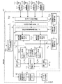
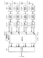
図1において、1−1〜1−4は受信アンテナ、2−1〜2−4は無線部、3はチャネル推定回路、4は受信信号管理回路、5は擬似受信信号管理回路、6−aは伝達関数行列管理回路、7は変換行列生成回路、8は伝達関数行列変換回路、9−aは送信ベクトル1次推定回路、10−1、10−2および15は幾何学的距離演算回路、11は送信信号生成回路、12−1、12−2および13はレプリカ生成回路、14−1、14−2および16−aは選択回路、17はデータ合成回路、20は変調部を示す。 In FIG. 1, 1-1 to 1-4 are reception antennas, 2-1 to 2-4 are radio units, 3 is a channel estimation circuit, 4 is a reception signal management circuit, 5 is a pseudo reception signal management circuit, and 6-a. Is a transfer function matrix management circuit, 7 is a conversion matrix generation circuit, 8 is a transfer function matrix conversion circuit, 9-a is a transmission vector primary estimation circuit, 10-1, 10-2 and 15 are geometric distance calculation circuits, 11 is a transmission signal generation circuit, 12-1, 12-2 and 13 are replica generation circuits, 14-1, 14-2 and 16-a are selection circuits, 17 is a data synthesis circuit, and 20 is a modulation unit.
受信アンテナ1−1〜1−4は、それぞれ個別に受信信号を受信する。無線部2−1〜2−4を経由して、受信した信号はチャネル推定回路3に入力される。送信側で付与した所定のプリアンブル信号の受信状況から、チャネル推定回路3にて各送信アンテナと受信アンテナ間の伝達関数を取得する。取得された各伝達関数の情報は、伝達関数行列管理回路6−aにて伝達関数行列Hとして管理される。この伝達関数行列Hは、変換行列生成回路7に入力される。ここでは、伝達関数行列Hをもとに、変換行列Zを生成する。この変換行列Zの生成の仕方については後述する。
The receiving antennas 1-1 to 1-4 receive the received signals individually. The received signal is input to the
この生成された変換行列Zは、伝達関数行列変換回路8に入力され、伝達関数行列管理回路6で管理されている行列との積としてZH・Hを演算により求める。また、伝達関数行列変換回路8では、ここで得られた行列から1≦j≦M1、かつ1≦i≦N1である第(j,i)成分より構成されるM1行N1列の第1部分行列H1と、M1+1≦j≦M1+M2、かつN1+1≦i≦N1+N2である第(j,i)成分を抜き出して構成されるM2行N2列の第2部分行列H2とを抜き出し、それぞれをレプリカ生成回路12−1および12−2に入力する。
The generated transformation matrix Z is input to the transfer function
一方、プリアンブル信号に後続して多重化された信号が受信された際には、受信アンテナ1−1〜1−4、無線部2−1〜2−4、チャネル推定回路3を経由した各系統の受信信号は、1シンボル単位で、受信信号管理回路4にて受信信号ベクトルRとして管理される。擬似受信信号管理回路5では、受信信号管理回路4から受信信号ベクトルRを、変換行列生成回路7から変換行列Zが入力され、この行列のエルミート共役である行列ZHと受信ベクトルRの積としてZH・Rを演算により求め、これを擬似受信信号R’として管理する。
On the other hand, when a signal multiplexed after the preamble signal is received, each system via the receiving antennas 1-1 to 1-4, the radio units 2-1 to 2-4, and the
一方、送信ベクトル1次推定回路9−aでは、チャネル推定回路3で取得した伝達関数行列Hと受信信号管理回路4で管理された受信信号Rから、送信信号ベクトルとして予想される信号を簡易な方法で取得する。この1次推定方法については後述する。ここで求めた送信ベクトルの1次推定値は、送信信号生成回路11に入力される。送信信号生成回路11では、送信ベクトル1次推定回路9−aから入力された送信信号ベクトルの推定値をもとに、その近傍の信号ベクトルを実際の送信信号に対する候補として生成する。例えば、64QAMであれば、信号系列毎に64種類の信号点を取り得るわけで、全体としては644個の候補が存在する。送信信号生成回路11では、その中から送信ベクトル1次推定回路9−aから入力された送信信号ベクトルの推定値に近いものだけに候補を限定して選ぶことになる。この限定の仕方については後述する。
On the other hand, in the transmission vector primary estimation circuit 9-a, a signal expected as a transmission signal vector is simply calculated from the transfer function matrix H acquired by the
ここで、送信信号ベクトルの候補は、ベクトルの第1成分から第N1成分までを抜き出したものと第N1+1成分から第N成分までを抜き出したものに分類され、前者をレプリカ生成回路12−1に、後者をレプリカ生成回路12−2に入力する。レプリカ生成回路12−1では、入力されたN1個の成分からなる各ベクトルに対して、M1行N1列の第1部分行列H1をかけた信号を、第1から第M1受信アンテナで受信される信号ベクトルのレプリカ信号として幾何学的距離演算回路10−1に入力する。幾何学的距離演算回路10−1では、擬似受信信号管理回路5で管理している擬似受信信号R’の第1成分から第M1成分までを抜き出し、このベクトルと先ほどのレプリカ信号との差分を幾何学的距離として取得する。選択回路14−1では、ここでの幾何学的距離を比較し、幾何学的距離が小さい方からK1個を選択し、その元となったK1個の送信信号ベクトルの候補をレプリカ生成回路13に入力する。
Here, the transmission signal vector candidates are classified into those extracted from the first component to the N 1st component of the vector and those extracted from the N 1 +1 component to the Nth component. The latter is input to the replica generation circuit 12-2. The replica generation circuit 12-1 receives the first to M 1th received signals obtained by multiplying each input vector composed of N 1 components by the first partial matrix H 1 of M 1 row N 1 column. The signal is input to the geometric distance calculation circuit 10-1 as a replica signal of the signal vector received by the antenna. In geometrical distance calculation circuit 10-1, extracted from the first component of the pseudo-received signal R 'managed by the pseudo received signal management circuit 5 until the M 1 component, the difference between the vector and the previous replica signal Is obtained as a geometric distance. The selection circuit 14-1 compares the geometric distances here, selects one K K from the one with the smallest geometric distance, and generates a replica of the K one transmission signal vector that is the origin of the K 1 transmission signal vector candidates. Input to the
以上の処理は、送信信号ベクトルの第N1+1成分から第N成分までを抜き出したものの候補についても同様に行う。具体的には、まず、第N1+1成分から第N成分までを抜き出した送信信号ベクトルの候補をレプリカ生成回路12−2に入力する。レプリカ生成回路12−2では、入力されたN2個の成分からなる各ベクトルに対して、M2行N2列の第2部分行列H2をかけた信号を、第M1+1から第M受信アンテナで受信される信号ベクトルのレプリカ信号として幾何学的距離演算回路10−2に入力する。 The above processing is similarly performed for candidates obtained by extracting from the N 1 +1 component to the Nth component of the transmission signal vector. Specifically, first, candidates for transmission signal vectors extracted from the N 1 + 1-th component to the N-th component are input to the replica generation circuit 12-2. In the replica generation circuit 12-2, a signal obtained by multiplying each input vector composed of N 2 components by the second partial matrix H 2 of M 2 rows and N 2 columns is obtained from the M 1 + 1th to the Mth. The signal is input to the geometric distance calculation circuit 10-2 as a replica signal of the signal vector received by the receiving antenna.
幾何学的距離演算回路10−2では、擬似受信信号管理回路5で管理している擬似受信信号R’の第M1+1成分から第M成分までを抜き出し、このベクトルと先ほどのレプリカ信号との差分を幾何学的距離として取得する。選択回路14−2では、ここでの幾何学的距離を比較し、幾何学的距離が小さい方からK2個を選択し、その元となったK2個の送信信号ベクトルの候補をレプリカ生成回路13に入力する。
In the geometric distance calculation circuit 10-2, the M 1 +1 to M-th components of the pseudo reception signal R ′ managed by the pseudo reception signal management circuit 5 are extracted, and this vector and the previous replica signal are extracted. The difference is obtained as a geometric distance. The selection circuit 14-2 compares the geometric distances here, selects K 2 pieces having the smallest geometric distance, and replicas K 2 transmission signal vector candidates from which the geometric distances are generated. Input to the
レプリカ生成回路13では、選択回路14−1から入力されたN1個の成分を持つベクトル(合計K1個)と、選択回路14−2から入力されたN2個の成分を持つベクトル(合計K2個)とを組み合わせて、N個(N=N1+N2)の成分を持つ合計K1×K2個のベクトルを生成し、これらのベクトルに伝達関数行列管理回路6−aで管理している伝達関数行列Hを乗算し、この信号をM本の受信アンテナで受信される信号ベクトルのレプリカ信号として幾何学的距離演算回路15に入力する。
In the
幾何学的距離演算回路15では、受信信号管理回路4で管理している受信信号Rと先ほどのレプリカ信号との差分を幾何学的距離として取得する。選択回路16−aでは、ここでの幾何学的距離を比較し、幾何学的距離が最も小さいものを選択し、その元となった送信信号ベクトルの候補を送信信号として確定する。これらのデータは、複数シンボルに渡って連続的に処理されるが、一連のデータを受信後、データ合成回路17にてデータとして再構成されて出力される。
In the geometric
上述した第1実施形態では、送信信号ベクトルの1次推定を行う際に、チャネル推定回路3から入力される伝達関数行列Hと、受信信号管理回路4で管理される受信信号ベクトルRから、第1次推定を行っている。このための最も簡単な方法はZF法であり、伝達関数行列Hの逆行列H−1、あるいはそのエルミート共役行列も用いた擬似逆行列(HH・H)−1・HHを受信信号ベクトルRに左から乗算し、H−1・Rまたは(HH・H)−1・HH・Rとして求めるものである。この他にも、MMSE法やQR分解法など、いかなる方法で1次推定を行っても構わない。
In the first embodiment described above, when performing the primary estimation of the transmission signal vector, the transfer function matrix H input from the
B.第2実施形態
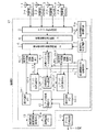
図2は、本発明の第2実施形態による受信局の構成を示すブロック図である。なお、図1に対応する部分には同一の符号を付けて説明を省略する。本第2実施形態では、図2に示すように、上述した第1実施形態の送信ベクトル1次推定回路9−aに代えて、送信ベクトル1次推定回路9−bを備えている点で異なる。
B. Second Embodiment FIG. 2 is a block diagram showing a configuration of a receiving station according to a second embodiment of the present invention. It should be noted that portions corresponding to those in FIG. As shown in FIG. 2, the second embodiment differs in that a transmission vector primary estimation circuit 9-b is provided instead of the transmission vector primary estimation circuit 9-a of the first embodiment described above. .
N行N列の伝達関数行列Hをもとに行う演算は、例えば逆行列を求める場合を例にとれば、Nが増加するにつれて急激にその演算量が増加し、回路規模的にも増加することになる。これを軽減するためには、行列の次数を下げて処理を行うことが効果的である。そのような場合には、伝達関数行列変換回路8で取得した2つの部分行列H1およびH2を用いることも可能である。
For example, in the case of calculating an inverse matrix, the calculation performed based on the transfer function matrix H of N rows and N columns increases abruptly as N increases, and also increases in circuit scale. It will be. In order to reduce this, it is effective to reduce the order of the matrix. In such a case, it is possible to use the two partial matrices H 1 and H 2 acquired by the transfer function
図2に示す構成例では、M1=M2=N1=N2=2であり、部分行列H1およびH2は共に2×2の行列である。この場合には、簡単な演算で逆行列を求めることができる。これらの逆行列H1 −1およびH2 −1(あるいは擬似逆行列(H1 H・H1)−1・H1 Hおよび(H2 H・H2)−1・H2 H)に、擬似受信信号管理回路5で管理している擬似受信信号R’の第1〜第2成分で表されるベクトルR’1、およびR’の第3〜第4成分で表されるベクトルR’2を乗算し、H1 −1・R’1、H2 −1・R’2(あるいは(H1 H・H1)−1・H1 H・R’1、(H2 H・H2)−1・H2 H・R’2)で与えられるベクトルを1次推定結果として用いることも可能である。 In the configuration example shown in FIG. 2, M 1 = M 2 = N 1 = N 2 = 2, and both the partial matrices H 1 and H 2 are 2 × 2 matrices. In this case, the inverse matrix can be obtained by a simple calculation. In these inverse matrices H 1 −1 and H 2 −1 (or pseudo inverse matrix (H 1 H · H 1 ) −1 · H 1 H and (H 2 H · H 2 ) −1 · H 2 H ), A vector R ′ 1 represented by the first to second components of the pseudo received signal R ′ managed by the pseudo received signal management circuit 5 and a vector R ′ 2 represented by the third to fourth components of R ′. H 1 −1 · R ′ 1 , H 2 −1 · R ′ 2 (or (H 1 H · H 1 ) −1 · H 1 H · R ′ 1 , (H 2 H · H 2 ) It is also possible to use a vector given by −1 · H 2 H · R ′ 2 ) as the primary estimation result.
C.第3実施形態
図3は、本発明の第3実施形態による受信局の構成を示すブロック図である。なお、図1に対応する部分には同一の符号を付けて説明を省略する。本第3実施形態では、図3に示すように、上述した第1実施形態の構成に加えて、信号入替え回路18を備えている点で異なる。
C. Third Embodiment FIG. 3 is a block diagram showing a configuration of a receiving station according to a third embodiment of the present invention. It should be noted that portions corresponding to those in FIG. As shown in FIG. 3, the third embodiment is different in that a
信号入替え回路18は、チャネル推定回路3からの伝達関数行列の情報を受け、信号系列毎の信号強度、信号対雑音比または信号対干渉雑音比を求め、その結果に応じて信号系列の入れ替えを行う変換行列Aを求め、これを伝達関数行列管理回路6−b、および選択回路16−bに入力する。伝達関数行列管理回路6−bでは、チャネル推定回路3から入力された伝達関数行列に対し、信号入替え回路18からの変換行列Aを乗算し、行列HをH・Aに置き換えて管理すると共に、変換行列生成回路7、伝達関数行列変換回路8およびレプリカ生成回路#3(13)に入力する。さらに、処理の最後においてこの入れ替え処理を元に戻すため、選択回路16−bでは、最終的に得られた送信信号の推定結果に対し、変換行列であるAを乗算し、信号系列の対応を図る。
The
なお、ここで用いる信号系列毎の送受信電力、信号対雑音比、信号対干渉雑音比等の指標は、入れ替え処理の他にも、各信号系列の送信信号の候補を絞り込む際の系列毎の候補の個数、すなわちn[1]、n[2]、n[3]、…、n[N]の値を決定する際にも用いるが、詳細は後述する。さらに、入れ替えのルールについても後述する。 In addition, indicators such as transmission / reception power, signal-to-noise ratio, signal-to-interference noise ratio, etc. for each signal series used here are candidates for each series when narrowing down transmission signal candidates for each signal series in addition to replacement processing. , I.e., n [1], n [2], n [3],..., N [N], will be described in detail later. Further, the replacement rule will be described later.
また、上述した受信局の構成において、図1から図3までの図中の点線で囲まれた領域が従来技術における図8の復調部121に相当する。したがって、OFDM変調方式を用いる場合には、図10に示すように、図10のサブキャリア毎の復調部212−1〜212−K)が図1における復調部20、図2における復調部21、および図3における復調部22に置き換えられることになる。
Further, in the configuration of the receiving station described above, a region surrounded by a dotted line in FIGS. 1 to 3 corresponds to the
次に、変換行列Zの求め方について、例としてN1=N2=M1=M2=2の場合について説明する。まず、伝達関数行列Hの各列をh[1]、h[2]、h[3]、h[4]と表記し、これを横に並べて、伝達関数行列Hを(h[1]、h[2]、h[3]、h[4])と表わす。同様に、変換行列Zの各列をz[1]、z[2]、z[3]、z[4]と表記し、それぞれを横に並べて、変換行列Zを(z[1]、z[2]、z[3]、z[4])と表わす。これを用いてZH・Hを表記すると以下のようになる。 Next, a method for obtaining the transformation matrix Z will be described as an example where N 1 = N 2 = M 1 = M 2 = 2. First, each column of the transfer function matrix H is expressed as h [1], h [2], h [3], h [4], and these are arranged side by side, and the transfer function matrix H is expressed as (h [1], h [2], h [3], h [4]). Similarly, each column of the transformation matrix Z is expressed as z [1], z [2], z [3], z [4], and is arranged side by side, and the transformation matrix Z is expressed as (z [1], z [2], z [3], z [4]). Using this, Z H · H is expressed as follows.
ここで、h[1]とz[3]、h[1]とz[4]、h[2]とz[3]、h[2]とz[4]、z[3]とz[4]が直交し、かつh[3]とz[1]、h[3]とz[2]、h[4]とz[1]、h[4]とz[2]、z[1]とz[2]が直交し、さらにz[1]、z[2]、z[3]、z[4]の絶対値が一致するように(すなわち、同一ベクトルの内積が全て等しくなるように)、ベクトルz[1]、z[2]、z[3]、z[4]を決定し、変換行列Zを生成する。この結果、行列の(1,3)、(1,4)、(2,3)、(2,4)、(3,1)、(3,2)、(4,1)、(4,2)成分は、上記条件より値がゼロとなっている。そこで、(1,1)、(1,2)、(2,1)、(2,2)成分で構成される2×2の行列H1と、(3,3)、(3,4)、(4,3)、(4,4)成分で構成される2×2の行列H2とを抜き出し、これらを用いて以降の処理を行うことができる。 Here, h [1] and z [3], h [1] and z [4], h [2] and z [3], h [2] and z [4], z [3] and z [3 4] are orthogonal, and h [3] and z [1], h [3] and z [2], h [4] and z [1], h [4] and z [2], z [1 ] And z [2] are orthogonal to each other, and the absolute values of z [1], z [2], z [3], and z [4] match (that is, the inner products of the same vector are all equal). ), Vectors z [1], z [2], z [3], z [4] are determined, and a transformation matrix Z is generated. As a result, the matrix (1,3), (1,4), (2,3), (2,4), (3,1), (3,2), (4,1), (4, 2) The value of the component is zero from the above conditions. Therefore, a 2 × 2 matrix H 1 composed of (1,1), (1,2), (2,1), (2,2) components, and (3,3), (3,4) , (4,3), (4,4) extracting a matrix of H 2 2 × 2 composed of components, it is possible to perform the subsequent processing using these.
なお、これらのベクトルを演算により求める手法は如何なるものを用いても構わないが、一例として以下の方法を示す。一般に、N次元ベクトルにおいて、それぞれが1次独立なN−1個のベクトルに対し、全てに直交するベクトルを生成するために「ベクトル積」(または「外積」)と呼ばれる幾何学演算手法がある。N−1個のベクトルをν1、ν2、…νN−1とし、これらのベクトルに対するベクトル積をOuter(ν1、ν2、ν3)と表記したとする。 Any method for obtaining these vectors by calculation may be used, but the following method is shown as an example. In general, there is a geometric calculation method called “vector product” (or “outer product”) in order to generate orthogonal vectors for N−1 vectors, each of which is linearly independent in N-dimensional vectors. . Assume that N−1 vectors are represented as ν 1 , ν 2 ,... Ν N−1, and the vector product for these vectors is represented as Outer (ν 1 , ν 2 , ν 3 ).
ここで、本発明の第1ないし第3実施形態のように、h[1]、h[2]、h[3]、h[4]およびz[1]、z[2]、z[3]、z[4]が4次元ベクトルであれば、例えばh[1]をν1に、h[2]をν2に、任意のベクトルの例として(1,0,0,0)をν3に対応させたとする。これに対してOuter(ν1、ν2、ν3)を求めると、h[1]、h[2]に直交したz[1]を取得することができる。この後、ν3とz[3]を入れ替えて、同様の計算でZ[4]が求まる。同様にしてz[1]、z[2]も求め、最後に規格化を行い、それぞれのベクトルの大きさを揃える。以上により、z[1]、z[2]、z[3]、z[4]を求めることができる。なお、この他にもグラム・シュミットの正規直交化法等を用いても構わない。 Here, as in the first to third embodiments of the present invention, h [1], h [2], h [3], h [4] and z [1], z [2], z [3 ], if four-dimensional vectors z [4] is, for example, the h [1] to [nu 1, the h [2] to [nu 2, as an example of optional vector (1,0,0,0) [nu 3 is assumed to correspond. On the other hand, when Outer (ν 1 , ν 2 , ν 3 ) is obtained, z [1] orthogonal to h [1] and h [2] can be obtained. Thereafter, ν 3 and z [3] are interchanged, and Z [4] is obtained by the same calculation. Similarly, z [1] and z [2] are also obtained and finally normalized, and the sizes of the respective vectors are made uniform. As described above, z [1], z [2], z [3], and z [4] can be obtained. In addition, Gram-Schmidt's orthonormalization method or the like may be used.
次に、信号系列毎の送受信電力、信号対雑音比、信号対干渉雑音比等の指標について具体例を示す。例えば、ある信号系列(第i送信アンテナからの信号を仮定)に対し、複数本のアンテナで受信された信号の信号対雑音比Wiは、以下の数式(5)で表わせる。 Next, specific examples of indices such as transmission / reception power, signal-to-noise ratio, and signal-to-interference noise ratio for each signal sequence will be shown. For example, for a certain signal sequence (assuming a signal from the i-th transmission antenna), the signal-to-noise ratio W i of signals received by a plurality of antennas can be expressed by the following equation (5).
ここで、hj,iは、第i送信アンテナと第j受信アンテナとの間の伝達関数、njは、第j受信アンテナで付加される熱雑音を表わす。通常、njの大きさを推定することは困難なうえ、njの大きさの期待値は、全受信アンテナで等しいので、分母の項を省略し、第i信号系列の送受信電力として以下のような数式(6)で代用するのが簡単である。 Here, h j, i represents a transfer function between the i-th transmitting antenna and the j-th receiving antenna, and n j represents thermal noise added by the j-th receiving antenna. Usually, after difficult to estimate the size of the n j, of n j magnitude of the expected value is equal in all the receiving antennas, omitted term in the denominator, the following as reception power of the i signal sequence It is easy to substitute the mathematical formula (6) like this.
同様に、信号対干渉雑音比についても、数式(7)または数式(8)にて求めることができる。 Similarly, the signal-to-interference / noise ratio can also be obtained by Expression (7) or Expression (8).
この他、N=Mの場合に例をとれば、第i送信アンテナに対応した信号の信号対雑音比の推定値は以下の数式(9)で代用することもできる。 In addition, taking an example in the case of N = M, the estimated value of the signal-to-noise ratio of the signal corresponding to the i-th transmitting antenna can be substituted by the following formula (9).
ここで、gj,iは、伝達関数行列Hの逆行列の第j,i成分を表す。この他にも、伝達関数行列Hに対してHH・Hの固有値を求め、第i固有値をWiとして代用しても良い。 Here, g j, i represents the j-th and i-th components of the inverse matrix of the transfer function matrix H. In addition to this, eigenvalues of H H · H with respect to the transfer function matrix H, may be substituted i-th eigenvalue as W i.
基本的に、上記指標Wiの値が大きな第i系列の信号ほど信号推定の信頼性が高く、先に推定した送信信号の1次推定結果の近傍に、真の送信信号があるものと期待される。このため、送信信号の候補を選ぶ際に、系統毎の候補の数の絞込み数、すなわちn[1]、n[2]、n[3]、…、n[N]の値は、信頼性が高いものほど小さくて良いと予想される。具体的な例として、W1>W2>W3>W4であったとする。この場合、1次推定結果の信頼性は、第1系統が最も高く、第2、第3、第4系統という順番となる。このような場合には、例えばn[1]の値としては4、n[2]の値としては9、n[3]の値としては25、n[4]の値としては64というように、n[1]≦n[2]≦n[3]≦n[4]となるように値を選ぶ。 Basically, the i-th sequence signal having a larger value of the index W i has higher signal estimation reliability, and it is expected that there is a true transmission signal in the vicinity of the first estimation result of the transmission signal estimated earlier. Is done. Therefore, when selecting transmission signal candidates, the number of candidates for each system, that is, the values of n [1], n [2], n [3],. It is expected that the higher the value, the smaller. As a specific example, it is assumed that W 1 > W 2 > W 3 > W 4 . In this case, the reliability of the primary estimation result is highest in the first system, and is in the order of the second, third, and fourth systems. In such a case, for example, the value of n [1] is 4, the value of n [2] is 9, the value of n [3] is 25, the value of n [4] is 64, and so on. , N [1] ≦ n [2] ≦ n [3] ≦ n [4].
次に、送信信号ベクトルの推定値に近いものだけに候補を限定して選ぶ際の限定の仕方について説明する。基本的な考え方は、第i信号系列においては、1次推定した送信信号ベクトルの第i成分に対し、その信号点に近い方からn[i]点を選ぶことが好ましい。例として64AQM等の変調方式を仮定すると、n[i]=4の場合、各コンスタレーション上の格子に対し、1次推定結果を含む四角い格子の4隅の点が第1〜第4近接の点となる。 Next, a description will be given of a limiting method when selecting and selecting candidates only for those close to the estimated value of the transmission signal vector. The basic idea is that, in the i-th signal series, it is preferable to select n [i] points from the one closer to the signal point for the i-th component of the transmission signal vector that is primarily estimated. Assuming a modulation scheme such as 64AQM as an example, when n [i] = 4, the four corner points of the square lattice including the primary estimation result are the first to fourth proximity points for the lattice on each constellation. It becomes a point.
これに対して、選択を簡易に実現するためには、一旦、信号点に対する硬判定を行い、その点を中心に第1近接の点、第2近接の点と範囲を広げていくことも可能である。例えば、n[i]=5の場合、1次推定結果の信号点に対して一旦硬判定を行い、第1近接の信号点を格子点上に求める。その後、その格子点の上下左右の点(硬判定点の第1近接点)を求め、これら5点を選べばよい。同様に、n[i]=9の場合、n[i]=5の時に求めた5点に加え、硬判定点からの第2近接点の4点を追加した9点を選べばよい。同様の処理は、その他のn[i]の値についても可能である。 On the other hand, in order to easily realize the selection, it is also possible to make a hard decision on the signal point once and expand the range of the first proximity point and the second proximity point around that point. It is. For example, when n [i] = 5, a hard decision is once performed on the signal point of the primary estimation result, and the first adjacent signal point is obtained on the lattice point. Thereafter, the upper, lower, left, and right points of the lattice points (first proximity points of the hard decision points) are obtained, and these five points may be selected. Similarly, in the case of n [i] = 9, in addition to the 5 points obtained when n [i] = 5, 9 points obtained by adding 4 points of the second proximity point from the hard decision point may be selected. Similar processing is possible for other values of n [i].
また、図3で示した入れ替え処理については、例えば以下のような方法で行えばよい。図3に示すように、N1=N2=2であれば、Wiの値が1番のものと4番のものをペアにし、2番と3番をペアにすると、グループ毎の信頼度が平均化される。あるいは、この場合、グループ毎の候補の総数は、n[1]×n[4]とn[2]×n[3]となるが、この候補数の値が平均化され、結果的に全体の候補数が最小化されるようにグループ分けを行えばよい。
Further, the replacement process shown in FIG. 3 may be performed by the following method, for example. As shown in FIG. 3, if
例えば、W1>W2>W3>W4の場合、の入れ替え処理は、第1系列はそのまま、第2系列⇒第3系列、第3系列⇒第4系列、第4系列⇒第2系列と入れ替えることになる。これを行列で示すと、変換行列Aは以下のようになる。 For example, in the case of W 1 > W 2 > W 3 > W 4 , the replacement process is as follows: the first series remains unchanged, the second series → the third series, the third series → the fourth series, the fourth series → the second series Will be replaced. When this is indicated by a matrix, the transformation matrix A is as follows.
この変換行列Aの特徴は、単位行列の行(または列)を適宜入れ替えたものとなっており、全ての行および列において、要素の1つが1、それ以外が0となっている。 The feature of this transformation matrix A is that the rows (or columns) of the unit matrix are appropriately replaced. In all the rows and columns, one of the elements is 1 and the other is 0.
ところで、上述した第1実施形態においては、式(1)に対し、式(4)で示すように両辺の左側から変換行列ZHを作用させ、式(1)を以下の式に変換して処理を行っていた。 Incidentally, in the first embodiment described above with respect to formula (1), it reacted with a transformation matrix Z H from the left side of both sides, as shown in Equation (4), to convert the formula (1) in the following equation We were processing.
これに対し、第3実施形態では、この変換行列Aを用い、式(12)を以下の式(13)、(14)、(15)ように変換する。 On the other hand, in the third embodiment, the transformation matrix A is used to transform equation (12) into the following equations (13), (14), and (15).
![]()
![]()
![]()
![]()
つまりH×Aで与えられる行列を元々の伝達関数行列Hに置き換えて処理を行う。この結果、変換行列Z自体も、Hに対する変換行列とは異なる行列になる。また、さらに最終的に求まった送信信号の推定結果ベクトルTbestも、式(15)のT’に相当するベクトルであるために、求めるべきベクトルは式(15)の両辺左からAを作用させ、行の入れ替え処理を施した以下の式(16)で求めることになる。 That is, processing is performed by replacing the matrix given by H × A with the original transfer function matrix H. As a result, the transformation matrix Z itself is also a different matrix from the transformation matrix for H. Furthermore, since the transmission signal estimation result vector T best finally obtained is also a vector corresponding to T ′ in the equation (15), the vector to be obtained is obtained by applying A from the left of both sides of the equation (15). Then, the following equation (16), which has been subjected to row replacement processing, is obtained.
![]()
![]()
以上のH×Aの処理、及びA×Tbestの処理は、行列Hの列の入れ替え及びベクトルTbestの行の入れ替えに相当するが、これはつまり、送信アンテナの番号付けの順序を入れ替えることに他ならない。したがって、上述した第1のアンテナ番号変換手段及び第2のアンテナ番号変換手段の具体的な実現方法としては、式(10)及び式(11)に示した変換行列を用いて上述した第3実施形態における処理を行えばよい。 The above H × A processing and A × T best processing correspond to the replacement of the columns of the matrix H and the replacement of the rows of the vector T best. In other words, this changes the order of the numbering of the transmission antennas. It is none other than. Therefore, as a specific method of realizing the first antenna number conversion unit and the second antenna number conversion unit described above, the third embodiment described above using the conversion matrixes shown in Equation (10) and Equation (11) is used. What is necessary is just to perform the process in a form.
なお、図3に示す第3実施形態では、図1に示す第1実施形態に対して入れ替え処理を追加した例を示したが、同様に図2に示す第2実施形態に入れ替え処理を追加することも当然ながら可能である。 In the third embodiment illustrated in FIG. 3, an example in which the replacement process is added to the first embodiment illustrated in FIG. 1 has been described. Similarly, the replacement process is added to the second embodiment illustrated in FIG. 2. Of course, it is possible.
上述した結果として、従来方式では、4(正確にはN1+N2)系列の信号系列に合わせて4次元のベクトルT[k]=(t1 [k],t2 [k],t3 [k],t4 [k])として送信信号ベクトルの候補を選んでいたが、これらが2系統に分割されたため、2次元ベクトルT1 [k]=(t1 [k],t2 [k])とT2 [k]=(t3 [k],t4 [k])として選ばれる。例えば、n[1]=4、n[2]=64、n[3]=9、n[2]=25とすると、1つ目のグループが4×64=256通り、2つ目のグループが9×25=225通り、合計で481通りの候補に減らすことができる。さらに、これらのベクトルに対してレプリカ信号を生成する場合には、2×2の行列演算で済むために、個々の演算の処理量も減らせることになる。 As a result of the above, in the conventional method, a four-dimensional vector T [k] = (t 1 [k] , t 2 [k] , t 3 according to a signal sequence of 4 (more precisely, N 1 + N 2 ) sequences. [K] , t 4 [k] ) have been selected as transmission signal vector candidates, but since these are divided into two systems, the two-dimensional vector T 1 [k] = (t 1 [k] , t 2 [ k] ) and T 2 [k] = (t 3 [k] , t 4 [k] ). For example, if n [1] = 4, n [2] = 64, n [3] = 9, and n [2] = 25, the first group is 4 × 64 = 256, the second group Can be reduced to a total of 481 candidates. Further, when replica signals are generated for these vectors, since a 2 × 2 matrix operation is sufficient, the processing amount of each operation can be reduced.
上述した図1から図3においては、このようにしてグループ毎に少数の候補を選び、それぞれに対してMLD処理を行う。例えば、送信信号生成回路11からは、レプリカ生成回路12−1および12−2に対して上記のT1 [k]とT2 [k]を出力し、ここで部分伝達関数行列H1およびH2を求める。各レプリカ信号は、H1・T1 [k]およびH2・T2 [k]で与えられ、これらと擬似受信信号管理回路5で管理する擬似受信信号R’の第1および第2成分を抜き出した2次元ベクトルR1と、擬似受信信号R’の第3および第4成分を抜き出した2次元ベクトルR2との間で幾何学的な距離を求める。その幾何学的な距離の小さいほうからK1個およびK2個選び出し、それぞれを組み合わせて4次元ベクトルとしての候補の送信信号ベクトルをK1×K2個選び出す。 In FIGS. 1 to 3 described above, a small number of candidates are selected for each group in this way, and the MLD process is performed on each of them. For example, the transmission signal generation circuit 11 outputs the above T 1 [k] and T 2 [k] to the replica generation circuits 12-1 and 12-2, where the partial transfer function matrices H 1 and H 2 is determined. Each replica signal is given by H 1 · T 1 [k] and H 2 · T 2 [k] , and these and the first and second components of the pseudo reception signal R ′ managed by the pseudo reception signal management circuit 5 a two-dimensional vector R 1 taken out to determine the geometric distance between the pseudo received signals R 2-dimensional vector R 2 obtained by extracting the third and fourth components'. K 1 and K 2 are selected from the smallest geometric distance, and K 1 × K 2 candidate transmission signal vectors as four-dimensional vectors are selected in combination.
このベクトルの組み合わせの操作は、具体的には、例えば1≦m1≦K1および1≦m2≦K2に対し、ユークリッド距離が小さい方からK1個およびK2個選び出したベクトルをT’1 [m1]=(t’1 [m1],t’2 [m1])およびT’2 [m2]=(t’3 [m2],t’4 [m2])とすると、組み合わせた最終的なベクトルは、次の数式(12)に示すようにして与えられる。
Specifically, for example, the vector combination operation is performed by using T ′ 1 to select vectors K 1 and K 2 from the smaller Euclidean distance with respect to 1 ≦
これらに対し、伝達関数行列管理回路6−aまたは6−bで管理されている伝達関数行列を乗算してレプリカ信号を生成し、該レプリカ信号と受信信号管理回路4で管理されている受信信号ベクトルRとを比較し、最も幾何学的な距離が小さいものを選択する。例として、K1=K2=8の場合を考えれば、最終的に処理を行う送信信号の候補の数は8×8=64通りに絞り込むことができる。
These are multiplied by the transfer function matrix managed by the transfer function matrix management circuit 6-a or 6-b to generate a replica signal, and the replica signal and the received signal managed by the received
D.第1実施形態および第2実施形態の受信処理
次に、図4は、前述した第1実施形態および第2実施形態による受信局の受信処理を示すフローチャートである。受信局では無線パケットを受信すると(S1)、プリアンブル信号を検出し(S2)、チャネル推定を実施する(S3)。ここでは、各送信アンテナおよび受信アンテナ間の伝達関数を全て取得する。チャネル推定により得られた伝達関数行列に対し、変換行列Zを演算により求め(S4)、伝達関数行列に変換行列Zのエルミート共役である行列ZHを乗算する(S5)。この結果として得られるZH・Hから、1≦j≦M1かつ1≦i≦N1である第(j,i)成分より構成されるM1行N1列の第1部分行列H1と、M1+1≦j≦M1+M2かつN1+1≦i≦N1+N2である第(j,i)成分を抜き出して構成されるM2行N2列の第2部分行列H2とを抜き出す(S6)。以上を実際のユーザデータが収容されたペイロード部分を受信する前に実施しておく。
D. Next, FIG. 4 is a flowchart showing the reception processing of the receiving station according to the first embodiment and the second embodiment described above. When the receiving station receives a radio packet (S1), it detects a preamble signal (S2) and performs channel estimation (S3). Here, all transfer functions between the transmission antennas and the reception antennas are acquired. To the transfer function matrix obtained by the channel estimation, obtained by calculating the transformation matrix Z (S4), multiplying the Hermitian conjugate of matrix Z H of the transformation matrix Z the transfer function matrix (S5). This resulting Z H · H, 1 ≦ j ≦
その後、ユーザデータが収用されたデータ部分の受信に対し、1シンボル毎に以下の処理を繰り返す。まず、第i受信アンテナで受信された信号をriとし、第i成分をriとする受信信号ベクトルをRとする(S7)。この受信信号ベクトルRに、先ほどの変換行列Zのエルミート共役である行列ZHを乗算し、擬似受信信号ベクトルR’を生成する(S8)。その後、送信信号ベクトルの1次推定を行い、ベクトルTzfを取得する(S9)。ここで、送信信号ベクトルの第1から第N1成分と、第N1+1成分から第N成分までを2つに分けて処理を行う。 Thereafter, the following processing is repeated for each symbol with respect to reception of the data portion in which the user data is expropriated. First, let R i be a signal received by the i-th receiving antenna and R be a received signal vector having the i-th component r i (S7). On the received signal vector R, multiplied by the matrix Z H is a Hermitian conjugate of the previous transformation matrix Z, generates a pseudo received signal vector R '(S8). Thereafter, the transmission signal vector is first-order estimated to obtain a vector T zf (S9). Here, the first to N 1st components of the transmission signal vector and the N 1 +1 to Nth components are processed in two.
まず、第1から第N1成分に関しては、1次推定したベクトルTzfの第1から第N1成分の各信号点に対し、それぞれその近傍のn[1]点、n[2]点、…、n[N1]点を選び出し、それぞれの組み合わせとしてn[1]×n[2]×…×n[N1]種類の第1部分送信ベクトルT1 [k]を生成する(S10a)。これらに、第1部分行列H1を乗算し、レプリカ信号H1・T1 [k]を生成する(S11a)。このレプリカ信号H1・T1 [k]と、処理S8で求めた擬似受信信号ベクトルR’の第1から第N1成分を抜き出した第1部分ベクトルR1とのユークリッド距離(一般的には幾何学的距離として、その他の物理量を用いて構わない)を求め(S12a)、これらの中からユークリッド距離の小さいものK1個の候補を選び出す(S13a)。 First, with respect to the first N 1 components from the first, for each signal point from the first of the N 1 component primary estimated vector T zf, n [1] points in the vicinity respectively, n [2] points, ..., n [N 1 ] points are selected, and n [1] × n [2] ×... × n [N 1 ] types of first partial transmission vectors T 1 [k] are generated as combinations (S10a). . These are multiplied by the first submatrix H 1 to generate a replica signal H 1 · T 1 [k] (S11a). The Euclidean distance between the replica signal H 1 · T 1 [k] and the first partial vector R 1 extracted from the first to N 1st components of the pseudo received signal vector R ′ obtained in step S8 (generally, as the geometric distance, and other may use the physical quantity) is obtained (S12a), select the smaller ones K 1 single candidate Euclidean distance from these (S13a).
同様に、第N1+1成分から第N成分に関しては、1次推定したベクトル符の第N1+1から第N成分の各信号点に対し、それぞれその近傍のn[N1+1]点、n[N1+2]点、…、n[N]点を選び出し、それぞれの組み合わせとしてn[N1+1]×n[N1+2]×…×n[N]種類の第2部分送信ベクトルT2 [k]を生成する(S10b)。これらに、第2分行列H2を乗算し、レプリカ信号H2・T2 [k]を生成する(S11b)。このレプリカ信号と、処理S8で求めた擬似受信信号ベクトルR’の第Nl+1から第N成分を抜き出した第2部分ベクトルR2とのユークリッド距離(一般的には幾何学的距離として、その他の物理量を用いて構わない)を求め(S12b)、これらの中からユークリッド距離の小さいものK2個の候補を選び出す(S13b)。その後、それぞれの候補を組み合わせてN次元ベクトルである最終的な送信信号ベクトルの候補Tfinal [k]を生成する(S14)。これに対し、伝達関数行列Hを乗算し、レプリカ信号H・Tfinal [k]を生成する(S15)。 Similarly, for the N 1 +1 to Nth components, n [N 1 +1] points in the vicinity of each of the N 1 +1 to Nth component signal points of the first-order estimated vector symbol, [N 1 +2] points,..., N [N] points are selected and n [N 1 +1] × n [N 1 +2] ×... × n [N] types of second partial transmission vectors T 2 are selected as combinations. [K] is generated (S10b). These are multiplied by the second branching matrix H 2 to generate the replica signal H 2 · T 2 [k] (S11b). The Euclidean distance between this replica signal and the second partial vector R 2 obtained by extracting the N-th component from the N 1 +1 of the pseudo received signal vector R ′ obtained in step S8 (generally as a geometric distance, other (S12b) and K 2 candidates having a short Euclidean distance are selected from these (S13b). Thereafter, the candidates are combined to generate a final transmission signal vector candidate T final [k] which is an N-dimensional vector (S14). On the other hand, the transfer function matrix H is multiplied to generate a replica signal H · T final [k] (S15).
このレプリカ信号H・Tfinal [k]と、受信信号ベクトルRのユークリッド距離(一般的には幾何学的距離として、その他の物理量を用いて構わない)を求め(S16)、これらの中からユークリッド距離の最も小さいものTbestを選び出す(S17)。この各成分で与えられる信号を各系列の送信信号として確定し(S18)、引き続き受信データがあるかどうかの判定を行い(S19)、データがあれば処理S7に戻り、処理S7〜処理S19を繰り返す。データの受信が完了した場合には、受信したデータを合成し、送信データを再生して出力し(S20)、受信処理を終了する(S21)。 The Euclidean distance (generally, other physical quantities may be used as the geometric distance ) between the replica signal H · T final [k] and the received signal vector R is obtained (S16), and Euclidean is selected from these. T best having the smallest distance is selected (S17). The signal given by each component is determined as a transmission signal of each series (S18), and it is subsequently determined whether there is received data (S19). If there is data, the process returns to process S7, and processes S7 to S19 are performed. repeat. When the reception of data is completed, the received data is synthesized, the transmission data is reproduced and output (S20), and the reception process is terminated (S21).
なお、上述した処理においては、処理S9の送信信号の1次推定の方法については言及していなかったが、第1実施形態においては、例えばZF法やMMSE法を用いる場合には、処理S3で伝連関数行列を取得後、処理S7までの間に各信号系列間の干渉キャンセルのための行列を演算により求めておく必要がある。例えば、伝達関数行列Hが正方行列であれば、伝達関数行列Hの逆行列H−1を求めておく。非正方行列であれば、擬似逆行列(HH・H)−1・HHを求めておく。また、MMSE法であれば、各信号系列の信号対雑音比を最大にする干渉キャンセル行列Fを求める。 In the above-described processing, the method of primary estimation of the transmission signal in step S9 is not mentioned. However, in the first embodiment, for example, when using the ZF method or the MMSE method, After obtaining the transmission function matrix, it is necessary to obtain a matrix for interference cancellation between the signal sequences by calculation until processing S7. For example, if the transfer function matrix H is a square matrix, an inverse matrix H −1 of the transfer function matrix H is obtained. If it is a non-square matrix, a pseudo inverse matrix (H H · H) −1 · H H is obtained. In the MMSE method, an interference cancellation matrix F that maximizes the signal-to-noise ratio of each signal sequence is obtained.
このM行N列の行列Fは、プリアンブル信号の第i信号系列における第ks(ksは1以上の整数)シンボルの送信信号をP(i,ks)および第j受信アンテナで受信される第ksシンボルの受信信号をr(j,ks)とし、かつP(i,ks)を第i成分として持つN行の列ベクトルをP(ks)、r(j,ks)を第j成分として持つM行の列ベクトルをr(ks)と表現した場合、プリアンブル信号を受信した際に、(F×r(ks)−P(ks))H×(F×r(ks)−P(ks))で与えられる物理量を最小とするように行列Fを選ぶ。処理S9では、ここで求めた行列を受信信号ベクトルRに乗算し、例えばH−1・R、または(HH・H)−1・HH・R、またはF・Rのようにして1次推定を行う。 This matrix F of M rows and N columns is the k-th received signal of the k-th (k is an integer of 1 or more) symbol transmission signal in the i-th signal sequence of the preamble signal by the P (i, ks) and j-th receiving antennas. The symbol received signal is r (j, ks), and the column vector of N rows having P (i, ks) as the i-th component is P (ks), and M having r (j, ks) as the j-th component. When a column vector of a row is expressed as r (ks), when a preamble signal is received, (F × r (ks) −P (ks)) H × (F × r (ks) −P (ks)) The matrix F is selected so as to minimize the physical quantity given by. In the process S9, the received signal vector R is multiplied by the matrix obtained here, and the first order is obtained, for example, H −1 · R or (H H · H) −1 · H H · R or F · R. Make an estimate.
一方、第2実施形態の場合には、処理S6で求めた第1および第2部分行列H1、H2に対し、処理S6の後で、かつ処理S7の前までの間に、逆行列または擬似逆行列としてH1 −1または(H1 H・H1)−1・H1 H、およびH2 −1または(H2 H・H2)−1・H2 Hを取得しておく。処理S8で求めた擬似受信信号ベクトルの第1から第N1成分を抜き出した第1部分ベクトルR1と、第N1+1から第N成分を抜き出した第2部分ベクトルR2に対し、先に求めた行列を用いて、例えばH1 −1・R1、H2 −1・R2のようにして処理S9の送信信号の1次推定を行う。
On the other hand, in the case of the second embodiment, the inverse matrix or the first and second sub-matrices H 1 and H 2 obtained in the
E.第3実施形態の受信処理
次に、図5は、前述した第3実施形態による受信局の受信処理を示すフローチャートである。図4にて説明した第1および第2実施形態との差分は、処理S3と処理S4の間に処理S31〜処理S33が追加になった点、および処理S18の後で処理S34が加えられた点である。処理S3で取得した伝達関数行列をもとに、例えば各信号系列の送受信電力を数式(6)を用いて求め(S31)、各信号系列の送受信電力に対する順序に合わせて数式(11)で与えられるような入れ替えのための行列を選択する(S32)。この行列を用いて伝達関数行列HをH・Aのように変換する(S33)。以下の処理S4〜処理S18の処理は、あたかもH・Aが元々の伝達関数行列であるかのように処理を行う。受信信号が決定されると(S18)、信号の入れ替え処理をA・Tbestにより行い(S34)、これを用いて送信データの再生を行う(S20)。
E. Reception Processing of Third Embodiment Next, FIG. 5 is a flowchart showing reception processing of the receiving station according to the third embodiment described above. The difference between the first and second embodiments described in FIG. 4 is that the processes S31 to S33 are added between the processes S3 and S4, and the process S34 is added after the process S18. Is a point. Based on the transfer function matrix acquired in the processing S3, for example, the transmission / reception power of each signal sequence is obtained using Equation (6) (S31), and given by Equation (11) according to the order of the transmission / reception power of each signal sequence. A matrix for replacement is selected (S32). Using this matrix, the transfer function matrix H is converted into H · A (S33). The following processes S4 to S18 are performed as if H · A is the original transfer function matrix. When the received signal is determined (S18), the signal switching process is performed by A · T best (S34), and the transmission data is reproduced using this (S20).
F.第1および第2実施形態の受信処理(OFDM変調方式)
次に、図6は、本発明の第1および第2実施形態に対して、OFDM変調方式を用いた場合の受信処理を示すフローチャートである。図4に示した第1および第2実施形態との差分は、処理S2にてプリアンブルを検出後、プリアンブル信号に対してシンボル単位でガードインターバルを除去し(S41)、FFT処理を行ってサブキャリア毎に分離し(S42)、図4における処理S3から処理S6を全サブキャリアに対して行う点と、同様にデータ受信時も、処理S7に先行してシンボル単位でガードインターバルを除去し(S43)、FFT処理を行ってサブキャリア毎に分離し(S44)、図4における処理S7から処理S18を全サブキャリアに対して行う点と、データ受信完了後、データを合成して送信データを再生する際に、全サブキャリアおよび全信号系列に渡り合成を行う(S45)点である。点線で囲まれた領域(処理S3〜処理S6、および処理S7〜処理S18)がサブキャリア毎に並列的に行われる処理である。
F. Reception processing of first and second embodiments (OFDM modulation system)
Next, FIG. 6 is a flowchart showing reception processing when the OFDM modulation scheme is used for the first and second embodiments of the present invention. The difference from the first and second embodiments shown in FIG. 4 is that, after the preamble is detected in process S2, the guard interval is removed from the preamble signal in symbol units (S41), and FFT processing is performed to obtain subcarriers. 4 is performed for all subcarriers. Similarly, when receiving data, the guard interval is removed in symbol units prior to processing S7 (S43). ), FFT processing is performed to separate each subcarrier (S44), and processing S7 to S18 in FIG. 4 are performed for all subcarriers. After data reception is completed, the data is combined to reproduce the transmission data. In this case, the synthesis is performed over all subcarriers and all signal sequences (S45). The area surrounded by the dotted line (process S3 to process S6 and process S7 to process S18) is a process performed in parallel for each subcarrier.
上述した説明においては、一例として送受信アンテナ数としてN1=N2=M1=M2=2の場合を例に取り説明したが、M≧3、N≧3、M1≧1、M2≧1、N1≧1、N2≧1で、かつM1+N2≦MおよびM2+N1≦Mおよび(N1+N2)=Nであれば任意の整数の組(M,M1,M2,N,N1,N2)において適用可能である。 In the above description, the case of N 1 = N 2 = M 1 = M 2 = 2 as an example of the number of transmission / reception antennas has been described as an example, but M ≧ 3, N ≧ 3, M 1 ≧ 1, M 2 If ≧ 1, N 1 ≧ 1, N 2 ≧ 1, and M 1 + N 2 ≦ M and M 2 + N 1 ≦ M and (N 1 + N 2 ) = N, any set of integers (M, M 1 , M 2 , N, N 1 , N 2 ).
以上述べた実施形態は、全て本発明を例示的に示すものであって限定的に示すものではなく、本発明は、他の種々の変形態様及び変更態様で実施することができる。したがって、本発明の範囲は、特許請求の範囲およびその均等範囲によってのみ規定されるものである。 The embodiments described above are all illustrative and do not limit the present invention, and the present invention can be implemented in other various modifications and changes. Therefore, the scope of the present invention is defined only by the claims and their equivalents.
なお、上述した実施形態においては、各回路は、基本的にはハードウェア上に実装されるものであるが、コンピュータシステム内で実行されるものであっても構わない。この場合、上述した変換行列生成回路5による一連の処理の過程は、プログラムの形式でコンピュータ読み取り可能な記録媒体に記憶されており、このプログラムをコンピュータが読み出して実行することによって、上記処理が行われる。すなわち、変換行列生成回路5における、各処理手段、処理部は、CPU等の中央演算処理装置がROMやRAM等の主記憶装置に上記プログラムを読み出して、情報の加工・演算処理を実行することにより、実現されるものであっても構わない。 In the above-described embodiment, each circuit is basically mounted on hardware, but may be executed in a computer system. In this case, a series of processing steps by the transformation matrix generation circuit 5 described above is stored in a computer-readable recording medium in the form of a program, and the above processing is performed by the computer reading and executing the program. Is called. That is, each processing means and processing unit in the transformation matrix generation circuit 5 is such that a central processing unit such as a CPU reads the above program into a main storage device such as a ROM or RAM, and executes information processing / calculation processing. May be realized.
ここでコンピュータ読み取り可能な記録媒体とは、磁気ディスク、光磁気ディスク、CD−ROM、DVD−ROM、半導体メモリ等をいう。また、このコンピュータプログラムを通信回線によってコンピュータに配信し、この配信を受けたコンピュータが当該プログラムを実行するようにしても良い。 Here, the computer-readable recording medium means a magnetic disk, a magneto-optical disk, a CD-ROM, a DVD-ROM, a semiconductor memory, or the like. Alternatively, the computer program may be distributed to the computer via a communication line, and the computer that has received the distribution may execute the program.
1〜1−4受信アンテナ
2−1〜2−4 無線部(受信手段)
3 チャネル推定回路(第1の取得手段)
4 受信信号管理回路(第4の取得手段)
5 擬似受信信号管理回路(第3の取得手段)
6−a〜6−b 伝達関数行列管理回路
7 変換行列生成回路(変換行列生成手段、算出手段)
8 伝達関数行列変換回路(第2の取得手段)
9−a〜9−c 送信ベクトル1次推定回路(送信ベクトル第1次推定手段)
10−1 幾何学的距離演算回路(第1の幾何学的距離算出手段)
10−2 幾何学的距離演算回路(第2の幾何学的距離算出手段)
11 送信信号生成回路(第5の取得手段、第6の取得手段)
12−1〜12−2 レプリカ生成回路
13 レプリカ生成回路(第9の取得手段)
14−1 選択回路(選択手段、第7の取得手段)
14−2 選択回路(選択手段、第8の取得手段)
15 幾何学的距離演算回路(第3の幾何学的距離算出手段)
16−a〜16−b 選択回路(第10の取得手段)
17 データ合成回路(再生手段)
18 信号入替え回路(第13の取得手段)
20 変調部
21 変調部
22 変調部
1-1-4 receiving antenna 2-1-2-4 wireless unit (receiving means)
3 channel estimation circuit (first acquisition means)
4 Received signal management circuit (fourth acquisition means)
5. Pseudo received signal management circuit (third acquisition means)
6-a to 6-b Transfer function
8 Transfer function matrix conversion circuit (second acquisition means)
9-a to 9-c Transmission vector primary estimation circuit (transmission vector primary estimation means)
10-1 Geometric distance calculation circuit (first geometric distance calculation means)
10-2 Geometric distance calculation circuit (second geometric distance calculation means)
11 Transmission signal generation circuit (fifth acquisition means, sixth acquisition means)
12-1 to 12-2
14-1 Selection circuit (selection means, seventh acquisition means)
14-2 Selection circuit (selection means, eighth acquisition means)
15 Geometric distance calculation circuit (third geometric distance calculation means)
16-a to 16-b selection circuit (tenth acquisition means)
17 Data synthesis circuit (reproduction means)
18 Signal replacement circuit (13th acquisition means)
20
Claims (22)
前記受信局は、
M本の前記受信アンテナを用いて個別に無線信号を受信する受信手段と、
受信信号に付与された既知のパターンの信号を参照信号として前記送信アンテナのうちの第iアンテナと前記受信アンテナのうちの第jアンテナとの間のM×N組の伝達関数hj,iを取得する第1の取得手段と、
第i送信アンテナと第j受信アンテナとの間の伝達関数hj,iを第(j,i)成分とするM行N列の行列、すなわち伝達関数行列Hおよび第j受信アンテナの受信信号を第j成分とするM行の列ベクトルRおよびN個の成分を有するN行の列ベクトルTに対し、前記伝達関数行列Hと前記列ベクトルTとの積であるH・Tに対してR=H・TのTに対する解または近似解として1次推定列ベクトルTzfを取得する送信ベクトル第1次推定手段と、
前記伝達関数行列Hの要素を元にM行(M1+M2)列の変換行列Zを生成する変換行列生成手段と、
前記変換行列Zのエルミート共役の行列ZHに対して前記伝達関数行列Hの積、すなわち(M1+M2)行(N1+N2)列の行列ZH・Hを算出する算出手段と、
該行列ZH・Hから1≦j≦M1かつ1≦i≦N1である第(j,i)成分より構成されるM1行N1列の第1部分行列H1と、M1+1≦j≦M1+M2かつN1+1≦i≦N1+N2である第(j,i)成分を抜き出して構成されるM2行N2列の第2部分行列H2とを取得する第2の取得手段と、
M個の受信信号を成分とするM行の列ベクトルRと前記変換行列のエルミート共役の行列ZHとの積、すなわち(M1+M2)行の列ベクトルZH・Rを取得する第3の取得手段と、
該列ベクトルZH・Rの第1成分から第M1成分までによって構成されるM1行の第1部分ベクトルをR1とし、かつ第M1+1成分から第M1+M2成分までを抜き出して構成されるM2行の第2部分ベクトルをR2としてR1およびR2を取得する第4の取得手段と、
1系列当りの送信信号としてNmax種類(1<Nmax、Nmaxは整数)の信号点の選択肢の中からその全てないしはその一部として前記1次推定列ベクトルTzfの第k(1≦k≦N、kは整数)成分の近傍に位置するn[k]点(1≦n[k]≦Nmax、Nmaxは整数)の送信信号を第k成分の送信信号の候補として選択する選択手段と、
第1から第N1番の各信号系列の送信信号を各成分として持つN1行の第1部分送信ベクトルをT1とした場合、該第1部分送信ベクトルT1の候補として、第1から第N1番の各信号系列の送信信号の各候補として選択された前記送信信号の候補をそれぞれN1個の各成分として持つ(n[1]×n[2]×…×n[N1])個のN1行の第1送信ベクトル候補群{T1 [k1]}(k1は識別番号)を取得する第5の取得手段と、
第N1+1から第N番の各信号系列の送信信号を各成分として持つN2行の第2部分送信ベクトルをT2とした場合、該第2部分送信ベクトルT2の候補として、第N1+1から第N番の各信号系列の送信信号の各候補として選択された前記送信信号の候補をそれぞれN2個の各成分として持つ(n(N1+1)×n[N1+2]×…×n[N]個のN2行の第2送信ベクトル候補群{T2 [k2]}(k2は識別番号)を取得する第6の取得手段と、
前記第1送信ベクトル候補群{T1 [k1]}のそれぞれに対し、R1とH1・T1 [k1]との幾何学的な距離を求める第1の幾何学的距離算出手段と、
1≦K1<(n[1]×n[2]×…×n[N1])である整数K1に対し、前記第1送信ベクトル候補群の中で該幾何学的な距離がm1番目(1≦m1≦K1、m1は整数)に小さい候補をT’1 [m1]と表記した場合に前記第1送信ベクトル候補群の部分集合としてK1個のベクトルで構成される限定第1送信ベクトル候補群{T’1 [m1]}を取得する第7の取得手段と、
前記第2送信ベクトル候補群{T2 [k2]}のそれぞれに対し、R2とH2・T2 [k2]との幾何学的な距離を求める第2の幾何学的距離算出手段と、
1≦K2<(n[N1+1]×n[N1+2]×…×n[N])である整数K2に対し、前記第2送信ベクトル候補群の中で該幾何学的な距離がm2番目(1≦m2≦K2、m2は整数)に小さい候補をT’2 [m2]と表記した場合に前記第2送信ベクトル候補群の部分集合としてK2個のベクトルで構成される限定第2送信ベクトル候補群{T’2 [m2]}を取得する第8の取得手段と、
前記限定第1送信ベクトル候補群{T’1 [m1]}の1つを第1から第N1番の各信号系列の送信信号を各成分として持ち、かつ前記限定第2送信ベクトル候補群{T’2 [m2]}の1つを第N1+1から第N番の各信号系列の送信信号を各成分として持つ合計K1×K2個のN行のベクトルを最終送信ベクトル候補群{Tfinal [k3]}(k3は識別番号)を取得する第9の取得手段と、
前記最終送信ベクトル候補群{Tfinal [k3]}のそれぞれに対し、前記伝達関数行列Hおよび前記受信ベクトルRを用いてRとH・Tfinal [k3]との幾何学的な距離を求める第3の幾何学的距離算出手段と、
該幾何学的な距離を最小とする送信ベクトルをTbestとして取得する第10の取得手段と、
該送信ベクトルTbestの各成分を各信号系列の送信信号の推定値とし、これらを合成することにより前記送信局におけるユーザデータを再生する再生手段と
を備えたことを特徴とする無線通信装置。 Integer N 1 as the M ≧ 3 become integer M, and the N ≧ 3 become integer N, 1 or M 1 + N 2 ≦ M and M 2 + N 1 ≦ M and (N 1 + N 2) = N, N 2 , M 1 , M 2 , a transmitting station including N or more transmitting antennas that multiplex and transmit a plurality of signal sequences on the same frequency channel in space, and a transmitted radio signal, A receiving station having M or more receiving antennas that perform reception processing by separating into a plurality of signal sequences, and the transmitting station divides input user data into N systems, and the N Means for generating a first signal sequence of N systems by assigning individual known pattern signals to the data divided into the systems, and simultaneously using the N transmission antennas, the signal sequences at the same frequency. Wireless communication system comprising means for transmitting in a superimposed manner A wireless communication device used on the receiving station side in a system,
The receiving station is
Receiving means for individually receiving radio signals using the M receiving antennas;
M × N sets of transfer functions h j, i between the i-th antenna of the transmitting antennas and the j-th antenna of the receiving antennas using a known pattern signal given to the received signal as a reference signal. First acquisition means for acquiring;
A matrix of M rows and N columns having the transfer function h j, i between the i-th transmitting antenna and the j-th receiving antenna as the (j, i) component, that is, the transfer function matrix H and the received signal of the j-th receiving antenna For an M-row column vector R, which is the j-th component, and an N-row column vector T having N components, R = for H · T, which is the product of the transfer function matrix H and the column vector T, Transmission vector primary estimation means for obtaining a primary estimation sequence vector T zf as a solution or approximate solution of H · T to T;
Transformation matrix generation means for generating a transformation matrix Z of M rows (M 1 + M 2 ) columns based on the elements of the transfer function matrix H;
A calculating means for calculating a product of the transfer function matrix H with respect to a Hermitian conjugate matrix Z H of the transformation matrix Z, that is, a matrix Z H · H of (M 1 + M 2 ) rows (N 1 + N 2 ) columns;
A first partial matrix H 1 of M 1 row N 1 column composed of the (j, i) -th component satisfying 1 ≦ j ≦ M 1 and 1 ≦ i ≦ N 1 from the matrix Z H · H, and M 1 Obtain a second submatrix H 2 of M 2 rows and N 2 columns configured by extracting the (j, i) component satisfying + 1 ≦ j ≦ M 1 + M 2 and N 1 + 1 ≦ i ≦ N 1 + N 2 A second acquisition means for:
A product of a column vector R of M rows having M received signals as a component and a Hermitian conjugate matrix Z H of the transformation matrix, that is, a column vector Z H · R of (M 1 + M 2 ) rows is obtained. Means for obtaining
The first partial vector of M 1 row composed of the first component to the M 1 component of the column vector Z H · R is set as R 1 , and the M 1 +1 component to the M 1 + M 2 component are extracted. Fourth acquisition means for acquiring R 1 and R 2 with the second partial vector of M 2 rows configured as R 2 as R 2 ;
As a transmission signal per sequence, all or a part of N max types (1 <N max , where N max is an integer) of signal point options are used as the k th (1 ≦ N) of the primary estimation sequence vector T zf . k ≦ N, k is an integer) Select a transmission signal at n [k] points (1 ≦ n [k] ≦ N max , where N max is an integer) located in the vicinity of the component as a candidate for the k-th component transmission signal. A selection means;
When the first partial transmission vector of N 1 rows having the transmission signals of the first to N 1st signal sequences as the respective components is T 1 , the first partial transmission vector T 1 is selected as the first partial transmission vector T 1. Each of the transmission signal candidates selected as each of the transmission signal candidates of the No. 1st signal sequence has N 1 components (n [1] × n [2] ×... × n [N 1 ] Fifth acquisition means for acquiring the first transmission vector candidate group {T 1 [k1] } of N 1 rows, where k1 is an identification number;
When the second partial transmission vector of N 2 rows having the transmission signals of the N 1 + 1th to N-th signal sequences as components is T 2 , the second partial transmission vector T 2 is selected as the Nth partial transmission vector T 2 . (N (N 1 +1) × n [N 1 +2] ×) each of which has the transmission signal candidate selected as each of the transmission signal candidates of the 1st to Nth signal sequences as N 2 components. ... Xn [N] N 2 rows of second transmission vector candidate groups {T 2 [k2] } (k2 is an identification number)
First geometric distance calculating means for obtaining a geometric distance between R 1 and H 1 · T 1 [k1] for each of the first transmission vector candidate groups {T 1 [k1] };
For an integer K 1 where 1 ≦ K 1 <(n [1] × n [2] ×... × n [N 1 ]), the geometric distance is m1 in the first transmission vector candidate group. When a candidate that is the smallest (1 ≦ m1 ≦ K 1 , where m1 is an integer) is denoted as T ′ 1 [m1] , a limited number consisting of K 1 vectors as a subset of the first transmission vector candidate group A seventh acquisition unit for acquiring one transmission vector candidate group {T ′ 1 [m1] };
Second geometric distance calculating means for obtaining a geometric distance between R 2 and H 2 · T 2 [k2] for each of the second transmission vector candidate groups {T 2 [k2] };
For an integer K 2 satisfying 1 ≦ K 2 <(n [N 1 +1] × n [N 1 +2] ×... × n [N]), the geometrical value in the second transmission vector candidate group is obtained. When a candidate whose distance is m2th (1 ≦ m2 ≦ K 2 , m2 is an integer) is expressed as T ′ 2 [m2] , the candidate is composed of K 2 vectors as a subset of the second transmission vector candidate group. 8th acquisition means for acquiring the limited second transmission vector candidate group {T ′ 2 [m2] },
One of the limited first transmission vector candidate groups {T ′ 1 [m1] } has a transmission signal of each signal sequence from No. 1 to N 1 as each component, and the limited second transmission vector candidate group { T ′ 2 [m2] } is used as a final transmission vector candidate group with a total of K 1 × K 2 N rows of vectors each having a transmission signal of each signal sequence from N 1 +1 to N-th as a component { N final acquisition means for acquiring T final [k3] } (k3 is an identification number);
For each of the final transmission vector candidate groups {T final [k3] }, the geometric distance between R and H · T final [k3] is obtained using the transfer function matrix H and the reception vector R. 3 geometric distance calculating means;
Tenth acquisition means for acquiring a transmission vector that minimizes the geometric distance as T best ;
A radio communication apparatus comprising: reproduction means for reproducing the user data in the transmitting station by using each component of the transmission vector T best as an estimated value of a transmission signal of each signal sequence and combining them.
前記伝達関数行列Hの第i列を抜き出して得られるM行の列ベクトルhiを用いて前記伝達関数行列Hを(h[1],h[2],…,h[N])と表記し、さらに前記変換行列Zの第i列を抜き出して得られるM行の列ベクトルziを用いてM行(M1+M2)列の行列Zを(z[1],z[2],…,z[M1+M2])と表記した場合、
M次元の複素空間において、N2個の列ベクトル群h[N1+1],h[N1+2],…,h[N1+N2]の全てに対して直交する空間に属し、かつそれぞれが互いに直交すると共に、絶対値の等しいM1個の列ベクトル群z[1],z[2],…,z[M1]を取得する第11の取得手段と、
N1個の列ベクトル群h[1],h[2],…,h[N1]の全てに対して直交する空間に属し、かつそれぞれが互いに直交すると共に、絶対値の等しいM2個の列ベクトル群z[M1+1],z[M1+2],…,z[M1+M2]を取得する第12の取得手段と
を備えたことを特徴とする請求項1記載の無線通信装置。 The receiving station is
Wherein the transfer function matrix the transfer function matrix H using a column vector h i of M rows obtained by extracting the i-th column of H (h [1], h [2], ..., h [N]) denoted Further, using a column vector z i of M rows obtained by extracting the i-th column of the transformation matrix Z, a matrix Z of M rows (M 1 + M 2 ) columns is expressed as (z [1], z [2], ..., z [M 1 + M 2 ])
In an M-dimensional complex space, each of the N 2 column vector groups h [N 1 +1], h [N 1 +2], ..., h [N 1 + N 2 ] belongs to a space orthogonal to each other, and Are orthogonal to each other and M 11 column vector groups z [1], z [2],..., Z [M 1 ] having the same absolute value are acquired;
N 1 single column vector group h [1], h [2 ], ..., h belong to the space orthogonal to all [N 1], and with each perpendicular to each other, equal M 2 pieces of absolute value 2. The radio according to claim 1, further comprising: a twelfth acquisition means for acquiring a column vector group z [M 1 +1], z [M 1 +2],..., Z [M 1 + M 2 ]. Communication device.
前記伝達関数行列Hを元に受信される信号系列毎の信号対雑音比または信号対干渉雑音比を推定する推定手段を備え、さらに、
前記第1の取得手段は、
前記推定手段で取得した受信される信号系列毎の信号対雑音比または信号対干渉雑音比に応じて前記伝達関数における送信アンテナ番号の番号付け順序を変更する第1のアンテナ番号変換手段を備え、さらに、
前記第10の取得手段は、
取得される送信ベクトルTbestの送信アンテナ番号の番号付けを、第1のアンテナ番号変換手段にて実施した入れ替え処理の逆処理により、元々のアンテナ番号に戻す第2のアンテナ番号変換手段を備えた
ことを特徴とする請求項1記載の無線通信装置。 The receiving station is
Estimating means for estimating a signal-to-noise ratio or a signal-to-interference noise ratio for each signal sequence received based on the transfer function matrix H;
The first acquisition means includes
First antenna number conversion means for changing the numbering order of transmission antenna numbers in the transfer function according to the signal-to-noise ratio or signal-to-interference noise ratio for each received signal sequence obtained by the estimation means, further,
The tenth acquisition means includes
There is provided second antenna number conversion means for returning the transmission antenna number of the acquired transmission vector T best to the original antenna number by reverse processing of the replacement processing performed by the first antenna number conversion means. The wireless communication apparatus according to claim 1.
前記伝達関数行列Hを元に受信される信号系列毎の総受信電力、信号対雑音比または信号対干渉雑音比のいずれかを推定する推定手段と、
前記n[1],n[2],n[3],…,n[N]の値を信号系列毎の総受信電力または信号対雑音比または信号対干渉雑音比の推定値に応じて決定する決定手段と
を備えたことを特徴とする請求項1記載の無線通信装置。 The receiving station is
Estimating means for estimating a total received power, a signal-to-noise ratio or a signal-to-interference noise ratio for each signal sequence received based on the transfer function matrix H;
The values of n [1], n [2], n [3],. The wireless communication apparatus according to claim 1, further comprising: a determining unit that
前記伝達関数行列Hと前記列ベクトルTとの積であるH・Tに対してR=H・TのTに対する解または近似解として前記1次推定列ベクトルTzfを取得するために、前記第1部分行列H1および第1部分ベクトルR1および第1送信ベクトルT1に対するR1=H1・T1の解または近似解として前記1次推定列ベクトルTzfの第1から第N1成分を取得する第16の取得手段と、
前記第2部分行列H2および第2部分ベクトルR2および第2送信ベクトルT2に対するR2=H2・T2の解または近似解として前記1次推定列ベクトルTzfの第N1+1から第N成分を取得する第17の取得手段と
を備えたことを特徴とする請求項1記載の無線通信装置。 The transmission vector primary estimation means includes:
In order to obtain the first estimated column vector T zf as a solution or approximate solution of R = H · T with respect to H · T that is a product of the transfer function matrix H and the column vector T, As a solution or approximate solution of R 1 = H 1 · T 1 for one submatrix H 1, first subvector R 1 and first transmission vector T 1 , the first to N 1st components of the primary estimated column vector T zf A sixteenth acquisition means for acquiring
From the N 1 +1 of the primary estimated column vector T zf as a solution or approximate solution of R 2 = H 2 · T 2 for the second partial matrix H 2, the second partial vector R 2 and the second transmission vector T 2 The wireless communication apparatus according to claim 1, further comprising: a seventeenth acquisition unit that acquires the Nth component.
前記伝達関数行列Hと前記列ベクトルTとの積であるH・Tに対してR=H・TのTに対する解または近似解として前記1次推定列ベクトルTzfを取得するために、前記伝達関数行列Hの逆行列H−1を前記列ベクトルRに作用させたベクトル積、すなわちH−1・Rにより取得する第18の取得手段を備えたことを特徴とする請求項1記載の無線通信装置。 The transmission vector primary estimation means includes:
In order to obtain the primary estimated column vector T zf as a solution or approximate solution of R = H · T with respect to H · T, which is the product of the transfer function matrix H and the column vector T, the transfer 2. The wireless communication according to claim 1, further comprising an eighteenth acquisition unit configured to acquire a vector product obtained by applying an inverse matrix H −1 of the function matrix H to the column vector R, that is, H −1 · R. apparatus.
前記伝達関数行列Hと前記列ベクトルTとの積であるH・Tに対してR=H・TのTに対する解または近似解として前記1次推定列ベクトルTzfを取得するために、前記伝達関数行列Hのエルミート共役行列HHおよび該伝達関数行列Hのベクトル積に対する逆行列、すなわち(HH・H)−1と、前記行列HHおよび前記列ベクトルRのベクトル積、すなわち(HH・H)−1・HH・Rにより取得する第19の取得手段を備えたことを特徴とする請求項1記載の無線通信装置。 The transmission vector primary estimation means includes:
In order to obtain the primary estimated column vector T zf as a solution or approximate solution of R = H · T with respect to H · T, which is the product of the transfer function matrix H and the column vector T, the transfer The inverse matrix of the Hermitian conjugate matrix H H of the function matrix H and the vector product of the transfer function matrix H, ie, (H H · H) −1 and the vector product of the matrix H H and the column vector R, ie (H H · H) radio communication apparatus according to claim 1, comprising the acquisition means 19 that acquires the -1 · H H · R.
前記送信ベクトル第1次推定手段は、
前記既知のパターンの信号を受信した際に、前記既知のパターンの信号の領域においてM行N列の行列Fに関して、ベクトルF×r(ks)−P(ks)および該ベクトルのエルミート共役のベクトル(F×r(ks)−P(ks))Hのベクトル積、すなわち(F×r(ks)−P(ks))H×(F×r(ks)−P(ks))で与えられる物理量を最小とするように前記行列Fを算出する算出手段と、
該行列Fと前記列ベクトルRのベクトル積、すなわちF・Rにより前記1次推定列ベクトルTzfを取得する第20の取得手段と
を備えたことを特徴とする請求項1記載の無線通信装置。 Reception of the k-th symbol received by the P (i, ks) and j-th receiving antennas of the k-th (k is an integer of 1 or more) symbol transmission signal in the i-th signal sequence of the N patterns of known patterns. A column of M rows having a signal vector of r (j, ks) and P (ks) as an i-th component and P (ks) as an i-th component and P (ks) as a j-th component of r (j, ks). When a vector is expressed as r (ks),
The transmission vector primary estimation means includes:
When the signal of the known pattern is received, the vector F × r (ks) −P (ks) and the Hermitian conjugate vector of the vector with respect to the matrix F of M rows and N columns in the region of the signal of the known pattern (F × r (ks) −P (ks)) is a vector product of H , ie, (F × r (ks) −P (ks)) H × (F × r (ks) −P (ks)) Calculating means for calculating the matrix F so as to minimize the physical quantity;
The radio communication apparatus according to claim 1, further comprising: a twentieth acquisition unit configured to acquire the primary estimated column vector T zf by a vector product of the matrix F and the column vector R, that is, F · R. .
前記受信局は、
M本の前記受信アンテナを用いて個別に無線信号を受信するステップと、
受信信号に付与された既知のパターンの信号を参照信号として前記送信アンテナのうちの第iアンテナと前記受信アンテナのうちの第jアンテナとの間のM×N組の伝達関数hj,iを取得するステップと、
第i送信アンテナと第j受信アンテナとの間の伝達関数hj,iを第(j,i)成分とするM行N列の行列、すなわち伝達関数行列Hおよび第j受信アンテナの受信信号を第j成分とするM行の列ベクトルRおよびN個の成分を有するN行の列ベクトルTに対し、前記伝達関数行列Hと前記列ベクトルTとの積であるH・Tに対してR=H・TのTに対する解または近似解として1次推定列ベクトルTzfを取得する送信ベクトル第1次推定ステップと、
前記伝達関数行列Hの要素を元にM行(M1+M2)列の変換行列Zを生成するステップと、
前記変換行列Zのエルミート共役の行列ZHに対して前記伝達関数行列Hの積、すなわち(M1+M2)行(N1+N2)列の行列ZH・Hを算出するステップと、
該行列ZH・Hから1≦j≦M1かつ1≦i≦N1である第(j,i)成分より構成されるM1行N1列の第1部分行列H1と、M1+1≦j≦M1+M2かつN1+1≦i≦N1+N2である第(j,i)成分を抜き出して構成されるM2行N2列の第2部分行列H2とを取得するステップと、
M個の受信信号を成分とするM行の列ベクトルRと前記変換行列のエルミート共役の行列ZHとの積、すなわち(M1+M2)行の列ベクトルZH・Rを取得するステップと、
該列ベクトルZH・Rの第1成分から第M1成分までによって構成されるM1行の第1部分ベクトルをR1とし、かつ第M1+1成分から第M1+M2成分までを抜き出して構成されるM2行の第2部分ベクトルをR2としてR1およびR2を取得するステップと、
1系列当りの送信信号としてNmax種類(1<Nmax、Nmaxは整数)の信号点の選択肢の中からその全てないしはその一部として前記1次推定列ベクトルTzfの第k(1≦k≦N、kは整数)成分の近傍に位置するn[k]点(1≦n[k]≦Nmax、Nmaxは整数)の送信信号を第k成分の送信信号の候補として選択するステップと、
第1から第N1番の各信号系列の送信信号を各成分として持つN1行の第1部分送信ベクトルをT1とした場合、該第1部分送信ベクトルT1の候補として、第1から第N1番の各信号系列の送信信号の各候補として選択された前記送信信号の候補をそれぞれN1個の各成分として持つ(n[1]×n[2]×…×n[N1])個のN1行の第1送信ベクトル候補群{T1 [k1]}(k1は識別番号)を取得するステップと、
第N1+1から第N番の各信号系列の送信信号を各成分として持つN2行の第2部分送信ベクトルをT2とした場合、該第2部分送信ベクトルT2の候補として、第N1+1から第N番の各信号系列の送信信号の各候補として選択された前記送信信号の候補をそれぞれN2個の各成分として持つ(n(N1+1)×n[N1+2]×…×n[N]個のN2行の第2送信ベクトル候補群{T2 [k2]}(k2は識別番号)を取得するステップと、
前記第1送信ベクトル候補群{T1 [k1]}のそれぞれに対し、R1とH1・T1 [k1]との幾何学的な距離を求めるステップと、
1≦K1<(n[1]×n[2]×…×n[N1])である整数K1に対し、前記第1送信ベクトル候補群の中で該幾何学的な距離がm1番目(1≦m1≦K1、m1は整数)に小さい候補をT’1 [m1]と表記した場合に前記第1送信ベクトル候補群の部分集合としてK1個のベクトルで構成される限定第1送信ベクトル候補群{T’1 [m1]}を取得するステップと、
前記第2送信ベクトル候補群{T2 [k2]}のそれぞれに対し、R2とH2・T2 [k2]との幾何学的な距離を求めるステップと、
1≦K2<(n[N1+1]×n[N1+2]×…×n[N])である整数K2に対し、前記第2送信ベクトル候補群の中で該幾何学的な距離がm2番目(1≦m2≦K2、m2は整数)に小さい候補をT’2 [m2]と表記した場合に前記第2送信ベクトル候補群の部分集合としてK2個のベクトルで構成される限定第2送信ベクトル候補群{T’2 [m2]}を取得するステップと、
前記限定第1送信ベクトル候補群{T’1 [m1]}の1つを第1から第N1番の各信号系列の送信信号を各成分として持ち、かつ前記限定第2送信ベクトル候補群{T’2 [m2]}の1つを第N1+1から第N番の各信号系列の送信信号を各成分として持つ合計K1×K2個のN行のベクトルを最終送信ベクトル候補群{Tfinal [k3]}(k3は識別番号)を取得するステップと、
前記最終送信ベクトル候補群{Tfinal [k3]}のそれぞれに対し、前記伝達関数行列Hおよび前記受信ベクトルRを用いてRとH・Tfinal [k3]との幾何学的な距離を求めるステップと、
該幾何学的な距離を最小とする送信ベクトルをTbestとして取得するステップと、
該送信ベクトルTbestの各成分を各信号系列の送信信号の推定値とし、これらを合成することにより前記送信局におけるユーザデータを再生するステップと
を有することを特徴とする無線通信方法。 Integer N 1 as the M ≧ 3 become integer M, and the N ≧ 3 become integer N, 1 or M 1 + N 2 ≦ M and M 2 + N 1 ≦ M and (N 1 + N 2) = N, N 2 , M 1 , M 2 , a transmitting station including N or more transmitting antennas that multiplex and transmit a plurality of signal sequences on the same frequency channel in space, and a transmitted radio signal, A receiving station having M or more receiving antennas that perform reception processing by separating into a plurality of signal sequences, and the transmitting station divides input user data into N systems, Generating a first signal sequence of N systems by assigning signals of individual known patterns to the data divided into the systems, and simultaneously using the N transmission antennas, the signal sequences at the same frequency. And the step of superimposing and transmitting A wireless communication method used on the receiving station side in a wireless communication system,
The receiving station is
Individually receiving radio signals using the M receiving antennas;
M × N sets of transfer functions h j, i between the i-th antenna of the transmitting antennas and the j-th antenna of the receiving antennas using a known pattern signal given to the received signal as a reference signal. A step to obtain,
A matrix of M rows and N columns having the transfer function h j, i between the i-th transmitting antenna and the j-th receiving antenna as the (j, i) component, that is, the transfer function matrix H and the received signal of the j-th receiving antenna For an M-row column vector R as the j-th component and an N-row column vector T having N components, R = for H · T, which is the product of the transfer function matrix H and the column vector T, A transmission vector primary estimation step for obtaining a primary estimation sequence vector T zf as a solution or approximate solution of H · T to T;
Generating a transformation matrix Z of M rows (M 1 + M 2 ) columns based on the elements of the transfer function matrix H;
Calculating a product of the transfer function matrix H with respect to a Hermitian conjugate matrix Z H of the transformation matrix Z, that is, a matrix Z H · H of (M 1 + M 2 ) rows (N 1 + N 2 ) columns;
A first partial matrix H 1 of M 1 row N 1 column composed of the (j, i) -th component satisfying 1 ≦ j ≦ M 1 and 1 ≦ i ≦ N 1 from the matrix Z H · H, and M 1 Obtain a second submatrix H 2 of M 2 rows and N 2 columns configured by extracting the (j, i) component satisfying + 1 ≦ j ≦ M 1 + M 2 and N 1 + 1 ≦ i ≦ N 1 + N 2 And steps to
Obtaining a product of an M row column vector R having M received signals as components and a Hermite conjugate matrix Z H of the transformation matrix, that is, a (M 1 + M 2 ) row column vector Z H · R; ,
The first partial vector of M 1 row composed of the first component to the M 1st component of the column vector Z H · R is set as R 1 , and the M 1 +1 component to the M 1 + M 2 component are extracted. acquiring a R 1 and R 2 the second partial vector of configured M 2 lines as R 2 Te,
As a transmission signal per sequence, all or a part of N max types (1 <N max , where N max is an integer) of signal point options are used as the k th (1 ≦ N) of the primary estimation sequence vector T zf . k ≦ N, k is an integer) Select a transmission signal at n [k] points (1 ≦ n [k] ≦ N max , where N max is an integer) located in the vicinity of the component as a candidate for the k-th component transmission signal. Steps,
When the first partial transmission vector of N 1 rows having the transmission signals of the first to N 1st signal sequences as the respective components is T 1 , the first partial transmission vector T 1 is selected as the first partial transmission vector T 1. Each of the transmission signal candidates selected as each of the transmission signal candidates of the No. 1st signal sequence has N 1 components (n [1] × n [2] ×... × n [N 1 ]) Obtaining the first transmission vector candidate group {T 1 [k1] } of N 1 rows, where k1 is an identification number;
When the second partial transmission vector of N 2 rows having the transmission signals of the N 1 + 1th to N-th signal sequences as components is T 2 , the second partial transmission vector T 2 is selected as the Nth partial transmission vector T 2 . (N (N 1 +1) × n [N 1 +2] ×) each of which has the transmission signal candidate selected as each of the transmission signal candidates of the 1st to Nth signal sequences as N 2 components. ... xn [N] N 2 rows of second transmission vector candidate groups {T 2 [k2] } (where k2 is an identification number);
Obtaining a geometric distance between R 1 and H 1 · T 1 [k1] for each of the first transmission vector candidate groups {T 1 [k1] };
For an integer K 1 where 1 ≦ K 1 <(n [1] × n [2] ×... × n [N 1 ]), the geometric distance is m1 in the first transmission vector candidate group. When a candidate that is the smallest (1 ≦ m1 ≦ K 1 , where m1 is an integer) is denoted as T ′ 1 [m1] , a limited number consisting of K 1 vectors as a subset of the first transmission vector candidate group Obtaining one transmission vector candidate group {T ′ 1 [m1] };
Obtaining a geometric distance between R 2 and H 2 · T 2 [k2] for each of the second transmission vector candidate groups {T 2 [k2] };
For an integer K 2 satisfying 1 ≦ K 2 <(n [N 1 +1] × n [N 1 +2] ×... × n [N]), the geometrical value in the second transmission vector candidate group is obtained. When a candidate whose distance is m2th (1 ≦ m2 ≦ K 2 , m2 is an integer) is expressed as T ′ 2 [m2] , the candidate is composed of K 2 vectors as a subset of the second transmission vector candidate group. Obtaining a limited second transmission vector candidate group {T ′ 2 [m2] },
One of the limited first transmission vector candidate groups {T ′ 1 [m1] } has a transmission signal of each signal sequence from No. 1 to N 1 as each component, and the limited second transmission vector candidate group { T ′ 2 [m2] } is used as a final transmission vector candidate group with a total of K 1 × K 2 N rows of vectors each having a transmission signal of each signal sequence from N 1 +1 to N-th as a component { Obtaining T final [k3] } (k3 is an identification number);
For each of the final transmission vector candidate groups {T final [k3] }, a step of obtaining a geometrical distance between R and H · T final [k3] using the transfer function matrix H and the reception vector R When,
Obtaining a transmission vector that minimizes the geometric distance as T best ;
And a step of reproducing user data at the transmitting station by combining each component of the transmission vector T best with an estimated value of a transmission signal of each signal sequence and combining them.
M次元の複素空間において、N2個の列ベクトル群h[N1+1],h[N1+2],…,h[N1+N2]の全てに対して直交する空間に属し、かつそれぞれが互いに直交すると共に、絶対値の等しいM1個の列ベクトル群z[1],z[2],…,z[M1]を取得するステップと、
N1個の列ベクトル群h[1],h[2],…,h[N1]の全てに対して直交する空間に属し、かつそれぞれが互いに直交すると共に、絶対値の等しいM2個の列ベクトル群z[M1+1],z[M1+2],…,z[M1+M2]を取得するステップと
をさらに有することを特徴とする請求項12記載の無線通信方法。 Wherein the transfer function matrix the transfer function matrix H using a column vector h i of M rows obtained by extracting the i-th column of H (h [1], h [2], ..., h [N]) denoted Further, using a column vector z i of M rows obtained by extracting the i-th column of the transformation matrix Z, a matrix Z of M rows (M 1 + M 2 ) columns is expressed as (z [1], z [2], ..., z [M 1 + M 2 ])
In an M-dimensional complex space, each of the N 2 column vector groups h [N 1 +1], h [N 1 +2],..., H [N 1 + N 2 ] belongs to a space orthogonal to each other, and with but perpendicular to each other, equal M 1 one column vector group z in absolute value [1], z [2] , ..., acquiring z [M 1],
N 1 single column vector group h [1], h [2 ], ..., h belong to the space orthogonal to all [N 1], and with each perpendicular to each other, equal M 2 pieces of absolute value 13. The wireless communication method according to claim 12, further comprising: acquiring a column vector group z [M 1 +1], z [M 1 +2],..., Z [M 1 + M 2 ].
推定した受信される信号系列毎の信号対雑音比または信号対干渉雑音比に応じて前記伝達関数における送信アンテナ番号の番号付け順序を変更する第1のアンテナ番号変換ステップと、
取得される送信ベクトルTbestの送信アンテナ番号の番号付けを、第1のアンテナ番号変換ステップにて実施した入れ替え処理の逆処理により、元々のアンテナ番号に戻す第2のアンテナ番号変換ステップと、
をさらに有することを特徴とする請求項12記載の無線通信方法。 Estimating a signal-to-noise ratio or a signal-to-interference noise ratio for each signal sequence received based on the transfer function matrix H;
A first antenna number converting step of changing a numbering order of transmitting antenna numbers in the transfer function according to the estimated signal-to-noise ratio or signal-to-interference noise ratio for each received signal sequence;
A second antenna number conversion step of returning the number of the transmission antenna number of the acquired transmission vector T best to the original antenna number by reverse processing of the replacement processing performed in the first antenna number conversion step;
The wireless communication method according to claim 12, further comprising:
前記n[1],n[2],n[3],…,n[N]の値を信号系列毎の総受信電力または信号対雑音比または信号対干渉雑音比の推定値に応じて決定するステップと
をさらに有することを特徴とする請求項12記載の無線通信方法。 Estimating a total received power, a signal-to-noise ratio, or a signal-to-interference noise ratio for each signal sequence received based on the transfer function matrix H;
The values of n [1], n [2], n [3],. The wireless communication method according to claim 12, further comprising the step of:
前記伝達関数行列Hと前記列ベクトルTとの積であるH・Tに対してR=H・TのTに対する解または近似解として前記1次推定列ベクトルTzfを取得するために、前記第1部分行列H1および第1部分ベクトルR1および第1送信ベクトルT1に対するR1=H1・T1の解または近似解として前記1次推定列ベクトルTzfの第1から第N1成分を取得するステップと、
前記第2部分行列H2および第2部分ベクトルR2および第2送信ベクトルT2に対するR2=H2・T2の解または近似解として前記1次推定列ベクトルTzfの第N1+1から第N成分を取得するステップと
をさらに有することを特徴とする請求項12記載の無線通信方法。 The transmission vector primary estimation step includes:
In order to obtain the first estimated column vector T zf as a solution or approximate solution of R = H · T with respect to H · T that is a product of the transfer function matrix H and the column vector T, As a solution or approximate solution of R 1 = H 1 · T 1 for one submatrix H 1, first subvector R 1 and first transmission vector T 1 , the first to N 1st components of the primary estimated column vector T zf Step to get the
From the N 1 +1 of the primary estimated column vector T zf as a solution or approximate solution of R 2 = H 2 · T 2 for the second partial matrix H 2, the second partial vector R 2 and the second transmission vector T 2 The wireless communication method according to claim 12, further comprising: acquiring an Nth component.
前記伝達関数行列Hと前記列ベクトルTとの積であるH・Tに対してR=H・TのTに対する解または近似解として前記1次推定列ベクトルTzfを取得するために、前記伝達関数行列Hの逆行列H−1を前記列ベクトルRに作用させたベクトル積、すなわちH−1・Rにより取得するステップをさらに有することを特徴とする請求項12記載の無線通信方法。 The transmission vector primary estimation step includes:
In order to obtain the primary estimated column vector T zf as a solution or approximate solution of R = H · T with respect to H · T, which is the product of the transfer function matrix H and the column vector T, the transfer 13. The wireless communication method according to claim 12, further comprising a step of obtaining a vector product obtained by applying an inverse matrix H- 1 of the function matrix H to the column vector R, that is, H- 1 · R.
前記伝達関数行列Hと前記列ベクトルTとの積であるH・Tに対してR=H・TのTに対する解または近似解として前記1次推定列ベクトルTzfを取得するために、前記伝達関数行列Hのエルミート共役行列HHおよび該伝達関数行列Hのベクトル積に対する逆行列、すなわち(HH・H)−1と、前記行列HHおよび前記列ベクトルRのベクトル積、すなわち(HH・H)−1・HH・Rにより取得するステップとを実施することを特徴とする請求項12記載の無線通信方法。 The transmission vector primary estimation step includes:
In order to obtain the primary estimated column vector T zf as a solution or approximate solution of R = H · T with respect to H · T, which is the product of the transfer function matrix H and the column vector T, the transfer The inverse matrix of the Hermitian conjugate matrix H H of the function matrix H and the vector product of the transfer function matrix H, ie, (H H · H) −1 and the vector product of the matrix H H and the column vector R, ie (H H The wireless communication method according to claim 12, wherein: (H) −1 · H H · R is acquired.
前記送信ベクトル第1次推定ステップは、
前記既知のパターンの信号を受信した際に、前記既知のパターンの信号の領域においてM行N列の行列Fに関して、ベクトルF×r(ks)−P(ks)および該ベクトルのエルミート共役のベクトル(F×r(ks)−P(ks))Hのベクトル積、すなわち(F×r(ks)−P(ks))H×(F×r(ks)−P(ks))で与えられる物理量を最小とするように前記行列Fを算出するステップと、
該行列Fと前記列ベクトルRのベクトル積、すなわちF・Rにより前記1次推定列ベクトルTzfを取得するステップと
をさらに有することを特徴とする請求項12記載の無線通信方法。 Reception of the k-th symbol received by the P (i, ks) and j-th receiving antennas of the k-th (k is an integer of 1 or more) symbol transmission signal in the i-th signal sequence of the N patterns of known patterns. A column of M rows having a signal vector of r (j, ks) and P (ks) as an i-th component and P (ks) as an i-th component and P (ks) as a j-th component of r (j, ks). When a vector is expressed as r (ks),
The transmission vector primary estimation step includes:
When the signal of the known pattern is received, the vector F × r (ks) −P (ks) and the Hermitian conjugate vector of the vector with respect to the matrix F of M rows and N columns in the signal region of the known pattern (F × r (ks) −P (ks)) is a vector product of H , that is, (F × r (ks) −P (ks)) H × (F × r (ks) −P (ks)) Calculating the matrix F so as to minimize the physical quantity;
The wireless communication method according to claim 12, further comprising: obtaining the primary estimated column vector T zf by a vector product of the matrix F and the column vector R, that is, F · R.
The transmitting station and the receiving station perform radio communication using an orthogonal frequency division multiplex modulation scheme, and individually perform processing according to claims 12 to 21 on a received signal after separation for each subcarrier. The wireless communication method according to any one of claims 12 to 21, wherein
Priority Applications (1)
| Application Number | Priority Date | Filing Date | Title |
|---|---|---|---|
| JP2005067210A JP4246169B2 (en) | 2005-03-10 | 2005-03-10 | Wireless communication apparatus and wireless communication method |
Applications Claiming Priority (1)
| Application Number | Priority Date | Filing Date | Title |
|---|---|---|---|
| JP2005067210A JP4246169B2 (en) | 2005-03-10 | 2005-03-10 | Wireless communication apparatus and wireless communication method |
Publications (2)
| Publication Number | Publication Date |
|---|---|
| JP2006254050A JP2006254050A (en) | 2006-09-21 |
| JP4246169B2 true JP4246169B2 (en) | 2009-04-02 |
Family
ID=37094062
Family Applications (1)
| Application Number | Title | Priority Date | Filing Date |
|---|---|---|---|
| JP2005067210A Expired - Fee Related JP4246169B2 (en) | 2005-03-10 | 2005-03-10 | Wireless communication apparatus and wireless communication method |
Country Status (1)
| Country | Link |
|---|---|
| JP (1) | JP4246169B2 (en) |
Families Citing this family (2)
| Publication number | Priority date | Publication date | Assignee | Title |
|---|---|---|---|---|
| WO2008032827A1 (en) * | 2006-09-15 | 2008-03-20 | Panasonic Corporation | Signal separating device and signal separating method |
| JP5042967B2 (en) * | 2008-11-07 | 2012-10-03 | ダイハツ工業株式会社 | Control device |
-
2005
- 2005-03-10 JP JP2005067210A patent/JP4246169B2/en not_active Expired - Fee Related
Also Published As
| Publication number | Publication date |
|---|---|
| JP2006254050A (en) | 2006-09-21 |
Similar Documents
| Publication | Publication Date | Title |
|---|---|---|
| US8971434B2 (en) | Precoding codebook and feedback representation | |
| JP5686427B2 (en) | Transmitting apparatus, receiving apparatus, wireless communication system, transmission control method, reception control method, and processor | |
| JP4290660B2 (en) | Spatial multiplexed signal detection circuit and spatial multiplexed signal detection method | |
| JP2010527562A (en) | Method and apparatus for feedback in closed loop transmission | |
| WO2009099013A1 (en) | Mobile communication system, reception device, and method | |
| US8116241B2 (en) | Wireless communication system and transmission device | |
| JP2006203685A (en) | Wireless communication system, wireless communication apparatus, wireless communication method, and computer program | |
| WO2015186531A1 (en) | Terminal device, feedback information generation method, and base station device | |
| JP5859913B2 (en) | Wireless receiver, wireless transmitter, wireless communication system, program, and integrated circuit | |
| JP4708206B2 (en) | Wireless communication method and wireless base station | |
| JP4802149B2 (en) | Signal detection apparatus, signal detection method, program thereof, and recording medium | |
| JP4246169B2 (en) | Wireless communication apparatus and wireless communication method | |
| JP4308159B2 (en) | Spatial multiplexed signal detection circuit | |
| JP4455512B2 (en) | Wireless communication method and wireless base station | |
| JP2012104988A (en) | Radio transmitter, radio receiver, radio communication system, and integrated circuit | |
| JP4455511B2 (en) | Wireless communication method, wireless communication system, and wireless terminal station | |
| JP4246164B2 (en) | Wireless communication apparatus and wireless communication method | |
| JP4188371B2 (en) | Wireless communication apparatus and wireless communication method | |
| JP5121752B2 (en) | Spatial multiplexed multicarrier receiver and spatially multiplexed multicarrier receiving method | |
| JP4476873B2 (en) | Wireless communication apparatus and wireless communication method | |
| JP4402098B2 (en) | Transmission apparatus and transmission directivity control method | |
| JP4327207B2 (en) | Wireless communication method and wireless communication device | |
| JP4230343B2 (en) | Wireless communication method, wireless communication system, and reception processing program | |
| JP4198583B2 (en) | Wireless communication apparatus and wireless communication method | |
| JP4105181B2 (en) | Wireless communication system and method |
Legal Events
| Date | Code | Title | Description |
|---|---|---|---|
| A621 | Written request for application examination |
Free format text: JAPANESE INTERMEDIATE CODE: A621 Effective date: 20070130 |
|
| A977 | Report on retrieval |
Free format text: JAPANESE INTERMEDIATE CODE: A971007 Effective date: 20081112 |
|
| TRDD | Decision of grant or rejection written | ||
| A01 | Written decision to grant a patent or to grant a registration (utility model) |
Free format text: JAPANESE INTERMEDIATE CODE: A01 Effective date: 20081219 |
|
| A01 | Written decision to grant a patent or to grant a registration (utility model) |
Free format text: JAPANESE INTERMEDIATE CODE: A01 |
|
| A61 | First payment of annual fees (during grant procedure) |
Free format text: JAPANESE INTERMEDIATE CODE: A61 Effective date: 20090107 |
|
| R151 | Written notification of patent or utility model registration |
Ref document number: 4246169 Country of ref document: JP Free format text: JAPANESE INTERMEDIATE CODE: R151 |
|
| FPAY | Renewal fee payment (event date is renewal date of database) |
Free format text: PAYMENT UNTIL: 20120116 Year of fee payment: 3 |
|
| FPAY | Renewal fee payment (event date is renewal date of database) |
Free format text: PAYMENT UNTIL: 20130116 Year of fee payment: 4 |
|
| S531 | Written request for registration of change of domicile |
Free format text: JAPANESE INTERMEDIATE CODE: R313531 |
|
| R350 | Written notification of registration of transfer |
Free format text: JAPANESE INTERMEDIATE CODE: R350 |
|
| LAPS | Cancellation because of no payment of annual fees |