JP4240350B2 - Multiband imaging device - Google Patents
Multiband imaging device Download PDFInfo
- Publication number
- JP4240350B2 JP4240350B2 JP2000053783A JP2000053783A JP4240350B2 JP 4240350 B2 JP4240350 B2 JP 4240350B2 JP 2000053783 A JP2000053783 A JP 2000053783A JP 2000053783 A JP2000053783 A JP 2000053783A JP 4240350 B2 JP4240350 B2 JP 4240350B2
- Authority
- JP
- Japan
- Prior art keywords
- image
- multiband
- light amount
- optical system
- image data
- Prior art date
- Legal status (The legal status is an assumption and is not a legal conclusion. Google has not performed a legal analysis and makes no representation as to the accuracy of the status listed.)
- Expired - Fee Related
Links
Images


Description
【0001】
【発明の属する技術分野】
本発明は、マルチバンド画像の技術分野に属し、詳しくは、光学系に起因する色むらや光量むらなどの光学系画像むらのない、高画質なマルチバンド画像を得られるマルチバンド画像撮影装置に関する。
【0002】
【従来の技術】
近年、撮影技術の進歩により、撮影対象の分光波形を実用上十分な精度で復元できる程度のチャンネル数を有する、マルチバンド画像撮影装置(マルチバンドカメラ)が実用化されつつある。これは、複数種類(多くは4種類以上)の光を透過する波長領域(マルチバンド)で、被写体を撮影して複数の画像(マルチバンド画像)を得るカメラである。
前記撮影装置の光学系は、CCDセンサ、色分解フィルタおよびレンズや、必要に応じて配置されるミラー等を主とした構成になっており、また、高速化、操作性の観点から、色分解フィルタとして液晶フィルタが使用され始めている。
【0003】
【発明が解決しようとする課題】
しかしながら、前記従来の撮影装置のような構成では、例えば、液晶フィルタの指向性によって生じる画面周辺部の特有の色むらや、レンズの性能に起因する周辺光量低下による光量むら等の光学系に起因する画像むら(光学系画像むら)を生じてしまい、画質を損なうという問題がある。
本発明は、前記従来の問題に鑑みてなされたものであり、マルチバンド画像撮影装置、特に、色分解フィルタとして液晶チューナブルフィルタ等の指向性のあるフィルタを用いるマルチバンド画像撮影装置であって、色分解フィルタやレンズ特性などの光学系に起因する色むらや光量むら等の光学系画像むらが除去された、高画質なマルチバンド画像を得ることのできるマルチバンド画像撮影装置を提供することを課題とする。
【0004】
【課題を解決するための手段】
前記課題を解決するために、本発明に係るマルチバンド画像撮影装置は、一様照度の被写体をマルチバンド画像撮影することによって得られた補正用画像データから得た光学系画像むら情報を保持する手段と、通常のマルチバンド画像撮影による通常のマルチバンド画像データの各画素位置に対応する前記光学系画像むら情報を用いて、前記通常のマルチバンド画像の光学系画像むら補正処理を行う手段とを備えたマルチバンド画像撮影装置であって、
前記一様照度の被写体を異なる光量レベルで撮影した複数の前記補正用画像データから得られた、前記光量レベルに応じた複数の光学系画像むら情報を有し、前記通常のマルチバンド画像データの光学系画像むら補正処理は、注目画素の強度に対応して、前記異なる光量レベルの光学系画像むら情報から選択した光学系画像むら情報、もしくは、前記異なる光量レベルの光学系画像むら情報を補間して得られた情報を用いて行うことを特徴とする。
【0007】
また、さらに、前記光学系画像むら情報および通常のマルチバンド画像データを、マルチバンド画像撮影装置の入出力特性を用いて光量値に変換する手段を有し、前記光量値に変換された光学系画像むら情報を、前記光量値に変換された通常のマルチバンド画像データから減算することによって、前記光学系画像むら補正処理を行うのが好ましい。
【0008】
あるいは、さらに、前記光学系画像むら情報および通常のマルチバンド画像データを、マルチバンド画像撮影装置の入出力特性を用いて光量値に変換する手段と、この光量値を対数変換して対数光量値に変換する手段とを有し、対数光量値に変換された光学系画像むら情報を、対数光量値に変換された通常のマルチバンド画像データから減算することによって、前記光学系画像むら補正処理を行うのが好ましい。
【0009】
また、指向性のあるフィルタを装着しているのが好ましく、さらに、この前記指向性のあるフィルタは、液晶チューナブルフィルタであるのが好ましい。
【0010】
さらに、一様照度の被写体をマルチバンド画像撮影する手段を有するのが好ましい。
【0011】
【発明の実施の形態】
以下、本発明に係るマルチバンド画像撮影装置について、添付の図面に示される好適実施形態を基に、詳細に説明する。
【0012】
図1は、本発明の第一実施形態に係るマルチバンド画像撮影装置の概略を表す、一部ブロック図を含む概略構成図である。
図1に示すように、マルチバンド画像撮影装置10は、基本的に、レンズ12とCCDカメラ14との間に液晶チューナブルフィルタ16を有している。
液晶チューナブルフィルタ16は、光の通過波長領域を変更できる、波長可変フィルタである。図示例においては、被写体20からの反射光を、複数設定された各チャンネル毎の波長領域で透過するように、マルチバンド画像撮影装置10を形成するコンピュータからの制御信号を受け取って所望のバンドパスフィルタとして機能する。液晶チューナブルフィルタ16としては、例えば、CRI社製のVarispec Tunable Filter 等の各種の市販品が利用可能である。
【0013】
このような液晶チューナブルフィルタ16を用いて撮影波長領域を複数のチャンネル、例えば16チャンネルに分割して、CCDカメラ14によって各チャンネル毎に同一の被写体20を撮影する。これにより、複数のスペクトル画像からなるマルチバンド画像を得る。
すなわち、CCDカメラ14は、所望の分光透過率分布に制御された液晶チューナブルフィルタ16を透過した透過光を、光学系のレンズ12を介してエリア状に配列したCCD素子の受光面で結像させ、波長領域の異なる各チャンネル毎に被写体を撮影したスペクトル画像信号を得る撮影手段である。従って、チャンネル数が16チャンネルであれば、16枚のスペクトル画像の画像信号が得られる。CCDカメラ14としては、例えば、DALSA社製CA−D4−1024A等の各種の市販品が利用可能である。
【0014】
このようにして、所定の光源18のあてられた被写体20を、液晶チューナブルフィルタ16を複数の異なる透過波長領域に調整して、分光感度の異なるチャンネル毎に撮影して、被写体20の色情報を有するマルチバンド画像を得る。
撮影された画像は画像メモリ22に格納される。
【0015】
また、マルチバンド画像撮影装置10は、本発明の特徴の一つである光学系画像むら(以下、単に画像むらとする)の補正処理を行う画像むら補正部24を有している。
マルチバンド画像撮影装置10は、(光学系)画像むら補正処理で用いる(光学系)画像むら情報となる、画像むらの補正用画像データを得るために、一様照度の被写体を撮影する。ここで、本実施形態においては、撮影の際に光量を調整して、複数の撮影光量で一様照度の被写体のマルチバンド画像を撮影し、光量レベルの異なる複数の補正用画像データを得るのが好ましく、そのための光量調整手段28を有する。この光量調整手段28は、黒あるいは白に近くないところで画像むら補正用画像データを得るためのもので、特に限定はされず、液晶バルブ、NDフィルタ等を用いればよい。また、撮影光量の調整は、露光時間(蓄積時間)の調整、光源18の光量調整等によって行ってもよい。
【0016】
補正用画像データを得るための一様照度の被写体の撮影手段には特に限定はなく、公知の方法が各種利用可能であり、例えば、全面的に均一な光を当てたグレーパッチ(無彩色のパッチ)を被写体とする撮影等が例示される。特に、図1に示すように、CCDカメラ14(レンズ12)の前に白いディフューザキャップ26を設置して、光源18によって所定光量の一様な光を照射して行うのが好ましい(すなわち、ディフューザキャップ26が、一様照度の被写体となる)。
また、前述のように、補正用画像データを得るためのマルチバンド画像の撮影は、撮影光量を変えて行い、複数の光量レベルにおけるマルチバンド画像を撮影するようにするのが好ましい。
【0017】
第一実施形態に係るマルチバンド画像撮影装置10は、撮影光量レベル別の補正用画像データから得た画像むら情報を用いることにより、出力信号が光量に対し非線型の場合に対応して、画像むら補正処理を行う。
そのため、画像むら補正部24は、補正用画像データから得られた画像むら情報を保管する補正データ保持部30、および実際に画像むら補正処理を行う補正処理部32とを有している。
【0018】
以下、第一実施形態の作用について説明する。
まず、事前に光量調整手段28を調整して、白いディフューザキャップ26をCCDカメラ14の前に配置して、一様照度の被写体のマルチバンド画像撮影を行う。このとき、光源18の光量を変えて、光量レベルの異なるマルチバンド画像を複数種類取得し、これを画像むらの補正用画像データとする。
【0019】
なお、本発明において、マルチバンド画像撮影は、特に限定はないが、具体的な一例として、撮影波長範囲410nm〜710nmを16分割して16チャンネルとし、各波長間隔を20nmとし、液晶チューナブルフィルタ16の分光透過率分布を各分割したチャンネルに応じて変化させて撮影する方法が例示される。
このようにして得られたマルチバンド画像データすなわち補正用画像データは、例えば、画像メモリ22に格納される。
【0020】
次いで、得られた補正用画像データを用いて、画像むら情報として、各光量レベル毎に、光学系に起因する色むらや光量むら等の画像むらの度合いを表す画像むら補正量を算出する。
補正用画像データは、一様照度の被写体を撮影して得られたものであるので、本来、一様の強度で撮影されるはずである。しかしながら、実際には、液晶チューナブルフィルタ16の指向性に起因する色むらや、レンズの周辺光量低下などに起因する光量むら等、マルチバンド画像撮影装置10の光学系に起因する画像むら(光学系画像むら)が発生する。
このような、画像むらを、補正用画像データの平均強度から各画素位置での強度を減算して求め、これを画像むら補正量として、補正データ保持部30に保管する。
【0021】
なお、画像むら情報は、上記画像むら補正量に限定はされず、例えば、中心画素(レンズ12光軸に対応する画素)を基準として、これと各画素との差分を画像むら情報としてもよい。また、補正用画像データそのものを画像むら情報として記憶し、通常のマルチバンド画像の画像むら補正時に、画像むら補正量等を算出してもよい。
画像むら情報(画像むら補正量)は、一度算出したら以降の全ての通常のマルチバンド画像の補正に用いてもよく、また、定期的に再算出して更新してもよく、また、液晶チューナブルフィルタ16やレンズ12の交換等、装置特性に大きな影響を与える変更がある場合に再算出して更新してもよく、また、通常のマルチバンド画像の撮影および画像むら補正を行う毎に画像むら情報を算出してもよい。さらに、一様照度被写体の撮影および画像むら補正量の算出と、通常のマルチバンド画像の撮影とは、平行して行ってもよい。
【0022】
このようにして、画像むら補正量(画像むら情報)を算出、補正データ保持部30に保管した上で、通常の条件で被写体20のマルチバンド画像撮影を行い、通常のマルチバンド画像データを得る。
このマルチバンド画像データは、画像メモリ22に記憶される。
【0023】
画像メモリ22に通常のマルチバンド画像データが記憶されると、補正処理部32が、補正対象となる通常のマルチバンド画像の各画素の強度を知見する。次いで、補正データ保持部30に保管されている前記光量レベル別の複数の画像むら補正量の中から、補正対象となるマルチバンド画像の各画素の位置および強度に応じた画像むら補正量を読み出す。
補正処理部32は、次いで、補正対象である通常のマルチバンド画像データから、これに対応する画像むら補正量を減算する。これにより、前述の色むらによるずれ量や光量むらが補正され、画像むらが補正されたマルチバンド画像が出力される。従って、本発明のマルチバンド画像撮影装置は、通常の画像撮影のみならず、画像計測等にも好適に利用可能である。
【0024】
上述の例では、マルチバンド画像の補正の際に、注目画素の強度に対応する画像むら補正量(画像むら情報)を選択し、これを用いて補正対象となるマルチバンド画像データを処理している。
しかしながら、本発明は、これに限定はされず、より高精度な補正を行うために、丁度対応する光量レベルの画像むら補正量が存在しない場合には、光量レベルの異なる複数の画像むら補正量を補間して、この補間によって得られた補正量を用いて、画像むら補正を行ってもよい。なお、この補間は、特に限定されるものではなく、通常は、それほど非線型の程度の甚だしい出力画像は少ないため、線型補間程度で間に合うものと思われる。
【0025】
以上説明した第一実施形態では、前述のように、撮影の光量レベル別に画像むら補正量(画像むら情報)を取っておくことにより、出力信号が光量に対し非線型の場合にも対応している。
これに対し、以下に説明する第二実施形態では、例えば、事前に求めたマルチバンド画像撮影装置(マルチバンドカメラ)の入出力特性を参照して、出力信号を光量に線型変換することにより、出力信号と光量とが非線形な場合でも、単一の画像むら情報でマルチバンド画像の画像むら補正を可能にしたものある。
【0026】
第二実施形態のマルチバンド画像撮影装置は、画像むら補正部以外については、第一実施形態と同様であり、画像むら補正部の構成のみが異なっている。
図2に、本発明の第二実施形態に係るマルチバンド画像撮影装置の画像むら補正部の概略を示す。図2に示すように、第二実施形態における画像むら補正部124は、入出力特性テーブル40、画像メモリ42、画像データ変換部44および補正処理部132を有している。
【0027】
入出力特性テーブル40は、マルチバンド画像撮影装置の入出力特性、具体的には、入力光量値と出力信号値(画像データ)との関係を示すもので、すなわち、両者を変換するテーブルである。これは、例えば、マルチバンド画像撮影装置の入出力特性情報等によって予め与えられる。
画像メモリ42は、入力されたマルチバンド画像データを格納するためのものである。なお、図示例のマルチバンド画像撮影装置は、画像むら補正部124の上流(画像データの流れ方向の上流)に、画像メモリ22を有しているので、特に画像メモリ42を有さず、画像メモリ22に、後述する画像メモリ42の作用をさせてもよい(逆も可)。
画像データ変換部44は、前記入出力特性テーブル40を用いて、画像データを出力信号値から光量値へ、またその反対に光量値から出力信号値へ、変換するものである。
補正処理部132は、光量値に変換された画像データによって、画像むら補正処理を行うものである。
【0028】
以下、第二実施形態の作用について説明する。
まず、事前に、光量(入力)に対する信号値(出力)の対応を示す入出力特性テーブル40を作成する。これは、前述したように、例えば、マルチバンド画像撮影装置(マルチバンドカメラ)の入出力特性を参照することによって作ることができるが、その作り方は、特に限定されるものではない。
一方、第一実施形態と同様にして、一様照度の被写体を撮影し、補正用画像データを得る。なお、この補正用画像データは、1つの光量レベルで撮影した、一つのマルチバンド画像データでよい。
また、通常のマルチバンド画像撮影を行い、通常のマルチバンド画像を取得する。これらの補正用画像データおよび通常のマルチバンド画像データは、共に、画像メモリ42に格納される。
【0029】
画像メモリ42(あるいは、画像メモリ22)に画像データが格納されると、画像データ変換部44が、前記補正用画像データと、通常のマルチバンド画像データとを、それぞれ入出力特性テーブル40を用いて、光量値に変換する。
さらに、補正処理部132が、光量値に変換された補正用画像データを用いて、前述の第一実施形態と同様にして画像むら補正量を算出すると共に、これを通常のマルチバンド画像データの光量値から減算することにより、画像むらを除去し、画像むら補正処理が行われる。
最後に、再び、画像データ変換部44において、入出力特性テーブル40を用いて、画像むら補正処理済の光量値を出力信号値に変換して、画像むらが補正されたマルチバンド画像として出力する。
【0030】
なお、本発明の第二実施形態においても、前記第一実施形態と同様に、予め、光量値に変換した補正用画像データから画像むら補正量を算出して、メモリ等に記憶しておき、マルチバンド画像の画像むら補正を行う際には、補正対象となるマルチバンド画像のみを光量値に変換して、メモリから画像むら補正量を読み出して、上記画像むら補正処理を行ってもよい。
【0031】
このように、画像データを光量値に変換して処理を行うことにより、単一の補正データで画像むら補正をすることができる。
【0032】
次いで、本発明の第三実施形態を説明する。
本発明の第三実施形態は、前記第二実施形態における光量変換に加え、さらに、光量値を対数変換した対数光量値として、この対数光量値を用いて、画像むらの補正を行うものである。
このような、本発明の第三実施形態では、単一の補正データで光量と出力信号とが非線形な場合でも好適に色むらや光量むら等の画像むらの補正を行うことができるのみならず、より高精度に、かつ、画像むらが大きい場合や、被写体20(マルチバンド画像)の光量(濃度)レンジが広い場合であっても、より好適に画像むらの補正を行うことができる。
【0033】
第三実施形態のマルチバンド画像撮影装置も、画像むら補正部以外については、第一実施形態と同様であり、画像むら補正部の構成のみが異なっている。
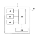
図3に、本発明の第三実施形態に係るマルチバンド画像撮影装置の画像むら補正部の概略を示す。図3に示すように、第三実施形態における画像むら補正部224は、入出力特性テーブル40、画像メモリ42、対数変換テーブル46、画像データ変換部244および補正処理部232を有している。
【0034】
入出力特性テーブル40および画像メモリ42は、前記第二実施形態と同様である。従って、画像メモリ22に、画像メモリ42の作用をさせてもよく、あるいは、特に画像メモリ42を有さなくてもよい。
対数変換テーブル46は、光量値を対数変換して対数光量値にし、逆に、対数光量値を指数変換して光量値に変換するテーブルである。なお、第三実施形態において、対数変換および指数変換はテーブルを用いるのに限定はされず、演算式によって行ってもよい。
画像データ変換部244は、画像データを出力信号値から光量値に変換し、さらに、対数光量値に変換し、また、その反対に、対数光量値から光量値に、さらに出力信号値へ、画像データを変換するものである。
補正処理部232は、対数光量値に変換された画像データによって、画像むら補正処理を行うものである。
【0035】
以下、第三実施形態の作用について説明する。
入出力特性テーブル40の作成、補正用画像データや通常のマルチバンド画像データの撮影、画像メモリ42への格納は、第二実施形態と同様である。
第三実施形態においては、さらに、事前に対数変換テーブル46を作成する。なお、対数変換テーブル46は、公知の方法で作成すればよい。
【0036】
画像メモリ42に画像データが格納されると、画像データ変換部244が、前記補正用画像データと、通常のマルチバンド画像データとを、それぞれ入出力特性テーブル40を用いて、光量値に変換する。画像データ変換部244は、さらに、光量値に変換された補正用画像データと通常のマルチバンド画像データを、対数変換テーブル46を用いて、対数光量値に変換する。
さらに、補正処理部232が、対数光量値に変換された補正用画像データを用いて、前述の第一実施形態と同様にして画像むら補正量を算出すると共に、これを通常のマルチバンド画像データの対数光量値から減算することにより、画像むらを除去し、画像むら補正処理が行われる。
最後に、再び、画像データ変換部244において、画像むら補正処理済の対数光量値を光量値に変換し、さらに、光量値を光量値を出力信号値に変換して、画像むらが補正されたマルチバンド画像として出力する。
【0037】
なお、本発明の第三実施形態においても、前記第一実施形態と同様に、予め、対数光量値に変換した補正用画像データから画像むら補正量を算出して、メモリ等に記憶しておいて、これを用いて、画像むら補正対象となるマルチバンド画像データの画像むら補正処理を行ってもよい。
【0038】
以上説明した、本発明の各実施形態によれば、マルチバンド画像撮影装置、特に、液晶チューナブルフィルタ等の指向性のあるフィルタを採用したマルチバンド画像撮影装置において、光学系に起因する色むらや光量むら等の画像むら(光学系画像むら)の除去された、高画質なマルチバンド画像を得ることができる。また、画像むらを除去したマルチバンド画像が得られるので、画像計測等の用途にも、好適に利用可能である。
【0039】
以上、本発明のマルチバンド画像撮影装置について詳細に説明したが、本発明は前記実施例に限定はされず、本発明の要旨を逸脱しない範囲において、各種の改良や変更を行ってもよいのは、もちろんである。
【0040】
【発明の効果】
以上説明した通り、本発明によれば、マルチバンド画像撮影装置、特に、液晶チューナブルフィルタ等の指向性のあるフィルタを採用したマルチバンド画像撮影装置において、フィルタに起因する色むらやレンズに起因する光量むら等、マルチバンド画像撮影装置の光学系に起因する画像むらが好適に除去された、高画質なマルチバンド画像を得ることができる。
【図面の簡単な説明】
【図1】 本発明の第一実施形態に係るマルチバンド画像撮影装置の概略を表す、一部ブロック図を含む概略構成図である。
【図2】 本発明の第二実施形態に係るマルチバンド画像撮影装置の画像むら補正部の概略を示すブロック図である。
【図3】 本発明の第三実施形態に係るマルチバンド画像撮影装置の画像むら補正部の概略を示すブロック図である。
【符号の説明】
10 マルチバンド画像撮影装置
12 レンズ
14 CCDカメラ
16 液晶チューナブルフィルタ
18 光源
20 被写体
22,42 画像メモリ
24,124,224 画像むら補正部
26 ディフューザキャップ
28 光量調整手段
30 補正データ保持部
32,132,232 補正処理部
40 入出力特性テーブル
44,244 画像データ変換部
46 対数変換テーブル[0001]
BACKGROUND OF THE INVENTION
The present invention belongs to the technical field of multiband images, and particularly relates to a multiband image photographing apparatus capable of obtaining high-quality multiband images without optical system unevenness such as color unevenness and light amount unevenness caused by an optical system. .
[0002]
[Prior art]
2. Description of the Related Art In recent years, multiband image photographing apparatuses (multiband cameras) having a number of channels that can restore a spectral waveform to be photographed with sufficient accuracy for practical use are being put into practical use due to advances in photographing technology. This is a camera that captures a subject and obtains a plurality of images (multi-band images) in a wavelength region (multi-band) that transmits a plurality of types (mostly four or more types) of light.
The optical system of the photographing apparatus is mainly composed of a CCD sensor, a color separation filter and a lens, a mirror arranged as necessary, and the color separation from the viewpoint of speeding up and operability. Liquid crystal filters are beginning to be used as filters.
[0003]
[Problems to be solved by the invention]
However, in the configuration of the conventional photographing apparatus, for example, due to an optical system such as a specific color unevenness in the peripheral portion of the screen caused by the directivity of the liquid crystal filter or a light amount unevenness due to a decrease in the peripheral light amount due to the performance of the lens. Image unevenness (optical system image unevenness) occurs, and image quality is impaired.
The present invention has been made in view of the above-described conventional problems, and is a multiband image photographing device, particularly a multiband image photographing device using a directional filter such as a liquid crystal tunable filter as a color separation filter. To provide a multiband image photographing apparatus capable of obtaining a high-quality multiband image from which optical image unevenness such as color unevenness and light amount unevenness due to an optical system such as a color separation filter and lens characteristics is removed. Is an issue.
[0004]
[Means for Solving the Problems]
In order to solve the above problems, a multiband image capturing device according to the present invention holds optical system image unevenness information obtained from correction image data obtained by capturing a multiband image of a subject with uniform illuminance. Means for performing optical system image unevenness correction processing of the normal multiband image using the optical system image unevenness information corresponding to each pixel position of normal multiband image data obtained by normal multiband image capturing; A multi-band image capturing apparatus comprising:
A plurality of optical image unevenness information corresponding to the light intensity levels obtained from the plurality of correction image data obtained by photographing the subject of uniform illuminance at different light intensity levels, and the normal multiband image data The optical system image unevenness correction process interpolates the optical system image unevenness information selected from the optical system image unevenness information of the different light amount level or the optical system image unevenness information of the different light amount level corresponding to the intensity of the target pixel. It is characterized by using the information obtained in this way.
[0007]
Further, the optical system has the means for converting the optical system image unevenness information and the normal multiband image data into a light amount value using input / output characteristics of the multiband image photographing device, and the optical system converted into the light amount value The optical system image unevenness correction process is preferably performed by subtracting image unevenness information from normal multiband image data converted into the light amount value.
[0008]
Alternatively, further, means for converting the optical system image unevenness information and normal multiband image data into a light amount value using input / output characteristics of the multiband image photographing device, and logarithmically converting the light amount value to log light amount values The optical system image unevenness correction process is performed by subtracting the optical system image unevenness information converted into the logarithmic light amount value from the normal multiband image data converted into the logarithmic light amount value. It is preferred to do so.
[0009]
In addition, it is preferable to attach a directional filter, and the directional filter is preferably a liquid crystal tunable filter.
[0010]
Furthermore, it is preferable to have means for taking a multiband image of a subject with uniform illuminance.
[0011]
DETAILED DESCRIPTION OF THE INVENTION
Hereinafter, a multiband image photographing apparatus according to the present invention will be described in detail based on a preferred embodiment shown in the accompanying drawings.
[0012]
FIG. 1 is a schematic configuration diagram including a partial block diagram showing an outline of the multiband image photographing apparatus according to the first embodiment of the present invention.
As shown in FIG. 1, the multiband
The liquid crystal
[0013]
The liquid crystal
That is, the
[0014]
In this way, the
The captured image is stored in the
[0015]
In addition, the multiband
The multiband
[0016]
There are no particular limitations on the means for photographing a subject with uniform illuminance to obtain correction image data, and various known methods can be used. For example, a gray patch (achromatic color) with uniform light applied to the entire surface can be used. For example, shooting with a patch) as a subject is exemplified. In particular, as shown in FIG. 1, it is preferable that a
Further, as described above, it is preferable to shoot a multiband image for obtaining correction image data by changing the photographic light quantity so as to shoot a multiband image at a plurality of light quantity levels.
[0017]
The multiband
Therefore, the image
[0018]
Hereinafter, the operation of the first embodiment will be described.
First, the light amount adjusting means 28 is adjusted in advance, and the
[0019]
In the present invention, multiband image capturing is not particularly limited, but as a specific example, the imaging wavelength range 410 nm to 710 nm is divided into 16 channels and each wavelength interval is 20 nm. An example is a method of photographing by changing the 16 spectral transmittance distributions according to each divided channel.
The multiband image data thus obtained, that is, the correction image data is stored in the
[0020]
Next, using the obtained correction image data, an image unevenness correction amount representing the degree of image unevenness such as color unevenness and light amount unevenness caused by the optical system is calculated as image unevenness information for each light amount level.
Since the image data for correction is obtained by photographing a subject with uniform illuminance, it should be originally photographed with uniform intensity. However, in actuality, image unevenness (optical) caused by the optical system of the multiband
Such image unevenness is obtained by subtracting the intensity at each pixel position from the average intensity of the correction image data, and this is stored in the correction
[0021]
The image unevenness information is not limited to the image unevenness correction amount. For example, the difference between each pixel and the center pixel (the pixel corresponding to the optical axis of the lens 12) may be used as the image unevenness information. . Further, the correction image data itself may be stored as image unevenness information, and an image unevenness correction amount or the like may be calculated when correcting the image unevenness of a normal multiband image.
The image unevenness information (image unevenness correction amount) may be used for correcting all normal multiband images after being calculated once, or may be periodically recalculated and updated. It may be recalculated and updated when there is a change that greatly affects the device characteristics, such as replacement of the
[0022]
In this way, the image unevenness correction amount (image unevenness information) is calculated and stored in the correction
The multiband image data is stored in the
[0023]
When normal multiband image data is stored in the
Next, the
[0024]
In the above example, when correcting a multiband image, an image unevenness correction amount (image unevenness information) corresponding to the intensity of the target pixel is selected, and this is used to process the multiband image data to be corrected. Yes.
However, the present invention is not limited to this, and in order to perform more accurate correction, when there is no corresponding image unevenness correction amount of the corresponding light amount level, a plurality of image unevenness correction amounts having different light amount levels are provided. The image unevenness may be corrected using the correction amount obtained by the interpolation. Note that this interpolation is not particularly limited, and normally, since there are few output images that are so nonlinear, it seems to be in time for linear interpolation.
[0025]
In the first embodiment described above, as described above, by taking an image unevenness correction amount (image unevenness information) for each photographing light amount level, it is possible to cope with a case where the output signal is non-linear with respect to the light amount. Yes.
On the other hand, in the second embodiment described below, for example, by referring to the input / output characteristics of the multiband image capturing device (multiband camera) obtained in advance, the output signal is linearly converted to the light amount, Even when the output signal and the amount of light are non-linear, it is possible to correct image unevenness of a multiband image with single image unevenness information.
[0026]
The multiband image capturing apparatus of the second embodiment is the same as that of the first embodiment except for the image unevenness correction unit, and only the configuration of the image unevenness correction unit is different.
FIG. 2 shows an outline of the image unevenness correction unit of the multiband image photographing apparatus according to the second embodiment of the present invention. As illustrated in FIG. 2, the image
[0027]
The input / output characteristic table 40 shows the input / output characteristics of the multiband image capturing apparatus, specifically, the relationship between the input light quantity value and the output signal value (image data), that is, a table for converting both. . This is given in advance by, for example, input / output characteristic information of the multiband image capturing apparatus.
The
The
The
[0028]
Hereinafter, the operation of the second embodiment will be described.
First, an input / output characteristic table 40 indicating the correspondence of the signal value (output) to the light amount (input) is created in advance. As described above, this can be created by referring to the input / output characteristics of a multiband image photographing device (multiband camera), for example, but the method of making is not particularly limited.
On the other hand, as in the first embodiment, a subject with uniform illuminance is photographed to obtain correction image data. The correction image data may be one multiband image data captured at one light quantity level.
Also, normal multiband image shooting is performed to obtain a normal multiband image. Both the correction image data and the normal multiband image data are stored in the
[0029]
When the image data is stored in the image memory 42 (or the image memory 22), the image
Further, the
Finally, in the image
[0030]
In the second embodiment of the present invention, as in the first embodiment, the image unevenness correction amount is calculated from the correction image data converted into the light amount value in advance and stored in a memory or the like. When performing image unevenness correction of a multiband image, only the multiband image to be corrected may be converted into a light amount value, the image unevenness correction amount may be read from the memory, and the image unevenness correction process may be performed.
[0031]
In this way, by converting the image data into the light amount value and performing the processing, it is possible to correct the image unevenness with a single correction data.
[0032]
Next, a third embodiment of the present invention will be described.
In the third embodiment of the present invention, in addition to the light amount conversion in the second embodiment, the log light amount value obtained by logarithmically converting the light amount value is used to correct image unevenness using the log light amount value. .
In the third embodiment of the present invention as described above, not only the unevenness of the color and the unevenness of the light amount can be suitably corrected even when the light amount and the output signal are non-linear with a single correction data. Even when the image unevenness is large with high accuracy and when the light amount (density) range of the subject 20 (multiband image) is wide, the image unevenness can be corrected more suitably.
[0033]
The multiband image capturing apparatus of the third embodiment is the same as that of the first embodiment except for the image unevenness correction unit, and only the configuration of the image unevenness correction unit is different.
FIG. 3 shows an outline of the image unevenness correction unit of the multiband image photographing apparatus according to the third embodiment of the present invention. As illustrated in FIG. 3, the image
[0034]
The input / output characteristic table 40 and the
The logarithmic conversion table 46 is a table that logarithmically converts the light quantity value to a logarithmic light quantity value, and conversely converts the logarithmic light quantity value to an exponential quantity to convert it into a light quantity value. In the third embodiment, logarithmic conversion and exponential conversion are not limited to using a table, and may be performed by an arithmetic expression.
The image
The
[0035]
Hereinafter, the operation of the third embodiment will be described.
The creation of the input / output characteristic table 40, the shooting of correction image data and normal multiband image data, and the storage in the
In the third embodiment, a logarithmic conversion table 46 is created in advance. The logarithmic conversion table 46 may be created by a known method.
[0036]
When the image data is stored in the
Further, the
Finally, in the image
[0037]
In the third embodiment of the present invention, as in the first embodiment, an image unevenness correction amount is calculated in advance from correction image data converted into logarithmic light amount values and stored in a memory or the like. Thus, this may be used to perform image unevenness correction processing for multiband image data to be subjected to image unevenness correction.
[0038]
According to each of the embodiments of the present invention described above, in the multiband image photographing device, in particular, in the multiband image photographing device employing a directional filter such as a liquid crystal tunable filter, the color unevenness caused by the optical system. In addition, it is possible to obtain a high-quality multiband image from which image unevenness (optical image unevenness) such as light amount unevenness is removed. Moreover, since a multiband image from which image unevenness has been removed can be obtained, it can be suitably used for applications such as image measurement.
[0039]
The multiband image photographing apparatus of the present invention has been described in detail above. However, the present invention is not limited to the above-described embodiments, and various improvements and modifications may be made without departing from the gist of the present invention. Of course.
[0040]
【The invention's effect】
As described above, according to the present invention, in a multiband image capturing device, particularly a multiband image capturing device employing a directional filter such as a liquid crystal tunable filter, the color unevenness caused by the filter and the lens are caused. It is possible to obtain a high-quality multiband image in which image unevenness due to the optical system of the multiband image photographing apparatus, such as unevenness in the amount of light, is suitably removed.
[Brief description of the drawings]
FIG. 1 is a schematic configuration diagram including a partial block diagram showing an outline of a multiband image photographing apparatus according to a first embodiment of the present invention.
FIG. 2 is a block diagram illustrating an outline of an image unevenness correction unit of a multiband image capturing apparatus according to a second embodiment of the present invention.
FIG. 3 is a block diagram illustrating an outline of an image unevenness correction unit of a multiband image capturing apparatus according to a third embodiment of the present invention.
[Explanation of symbols]
DESCRIPTION OF
Claims (6)
通常のマルチバンド画像撮影による通常のマルチバンド画像データの各画素位置に対応する前記光学系画像むら情報を用いて、前記通常のマルチバンド画像の光学系画像むら補正処理を行う手段とを備えたマルチバンド画像撮影装置であって、
前記一様照度の被写体を異なる光量レベルで撮影した複数の前記補正用画像データから得られた、前記光量レベルに応じた複数の光学系画像むら情報を有し、
前記通常のマルチバンド画像データの光学系画像むら補正処理は、注目画素の強度に対応して、前記異なる光量レベルの光学系画像むら情報から選択した光学系画像むら情報、もしくは、前記異なる光量レベルの光学系画像むら情報を補間して得られた情報を用いて行うことを特徴とするマルチバンド画像撮影装置。Means for holding optical system image unevenness information obtained from correction image data obtained by taking a multiband image of a subject with uniform illuminance;
Means for performing optical system image unevenness correction processing of the normal multiband image using the optical system image unevenness information corresponding to each pixel position of normal multiband image data obtained by normal multiband image capturing. A multi-band image capturing device,
A plurality of optical system image unevenness information corresponding to the light amount level obtained from the plurality of correction image data obtained by photographing the subject of uniform illuminance at different light amount levels,
In the normal multiband image data optical system image unevenness correction processing, the optical system image unevenness information selected from the optical system image unevenness information of the different light amount levels or the different light amount levels corresponding to the intensity of the target pixel. A multiband image photographing apparatus characterized by using information obtained by interpolating optical system image unevenness information .
さらに、前記光学系画像むら情報および通常のマルチバンド画像データを、マルチバンド画像撮影装置の入出力特性を用いて光量値に変換する手段を有し、
前記光量値に変換された光学系画像むら情報を、前記光量値に変換された通常のマルチバンド画像データから減算することによって、前記光学系画像むら補正処理を行うマルチバンド画像撮影装置。The multiband image capturing apparatus according to claim 1,
Furthermore, the optical system image unevenness information and normal multiband image data has means for converting into light amount values using input / output characteristics of the multiband image photographing device,
A multiband image photographing apparatus that performs the optical system image unevenness correction process by subtracting the optical system image unevenness information converted into the light amount value from normal multiband image data converted into the light amount value.
さらに、前記光学系画像むら情報および通常のマルチバンド画像データを、マルチバンド画像撮影装置の入出力特性を用いて光量値に変換する手段と、この光量値を対数変換して対数光量値に変換する手段とを有し、
対数光量値に変換された光学系画像むら情報を、対数光量値に変換された通常のマルチバンド画像データから減算することによって、前記光学系画像むら補正処理を行うマルチバンド画像撮影装置。The multiband image capturing apparatus according to claim 1,
Further, means for converting the optical system image unevenness information and normal multiband image data into a light amount value using input / output characteristics of the multiband image photographing device, and logarithmically converting the light amount value into a logarithmic light amount value. And means for
A multiband image photographing apparatus that performs the optical system image unevenness correction processing by subtracting optical system image unevenness information converted into logarithmic light amount values from normal multiband image data converted into logarithmic light amount values.
Priority Applications (1)
| Application Number | Priority Date | Filing Date | Title |
|---|---|---|---|
| JP2000053783A JP4240350B2 (en) | 1999-08-30 | 2000-02-29 | Multiband imaging device |
Applications Claiming Priority (3)
| Application Number | Priority Date | Filing Date | Title |
|---|---|---|---|
| JP24272699 | 1999-08-30 | ||
| JP11-242726 | 1999-08-30 | ||
| JP2000053783A JP4240350B2 (en) | 1999-08-30 | 2000-02-29 | Multiband imaging device |
Publications (3)
| Publication Number | Publication Date |
|---|---|
| JP2001145116A JP2001145116A (en) | 2001-05-25 |
| JP2001145116A5 JP2001145116A5 (en) | 2005-10-27 |
| JP4240350B2 true JP4240350B2 (en) | 2009-03-18 |
Family
ID=26535895
Family Applications (1)
| Application Number | Title | Priority Date | Filing Date |
|---|---|---|---|
| JP2000053783A Expired - Fee Related JP4240350B2 (en) | 1999-08-30 | 2000-02-29 | Multiband imaging device |
Country Status (1)
| Country | Link |
|---|---|
| JP (1) | JP4240350B2 (en) |
Families Citing this family (4)
| Publication number | Priority date | Publication date | Assignee | Title |
|---|---|---|---|---|
| WO2006030644A1 (en) * | 2004-09-14 | 2006-03-23 | Konica Minolta Holdings, Inc. | Camera and image display device in which the camera is assembled |
| JP5040628B2 (en) * | 2007-12-10 | 2012-10-03 | カシオ計算機株式会社 | Imaging apparatus, printing system, imaging apparatus control program, and imaging apparatus control method |
| JP2008158535A (en) * | 2008-01-10 | 2008-07-10 | Mitsubishi Electric Corp | Imaging apparatus |
| JP5614230B2 (en) * | 2009-12-14 | 2014-10-29 | 住友電気工業株式会社 | Image shooting device |
-
2000
- 2000-02-29 JP JP2000053783A patent/JP4240350B2/en not_active Expired - Fee Related
Also Published As
| Publication number | Publication date |
|---|---|
| JP2001145116A (en) | 2001-05-25 |
Similar Documents
| Publication | Publication Date | Title |
|---|---|---|
| US7969483B2 (en) | White balance control method, imaging apparatus and storage medium storing white balance control program | |
| CN102844788B (en) | Image processing apparatus and use the image pick-up device of this image processing apparatus | |
| US7920172B2 (en) | Method of controlling an action, such as a sharpness modification, using a colour digital image | |
| US7190845B2 (en) | Image correction according to transmission characteristics of image sensing optical system | |
| JP6004221B2 (en) | Image processing device | |
| US8040412B2 (en) | Imaging apparatus and image data correcting method | |
| JP2001086383A (en) | Method and device for forming image | |
| US6356304B1 (en) | Method for processing video signal and apparatus for processing video signal | |
| JP4240350B2 (en) | Multiband imaging device | |
| JP4295149B2 (en) | Color shading correction method and solid-state imaging device | |
| US20070019105A1 (en) | Imaging apparatus for performing optimum exposure and color balance control | |
| GB2460241A (en) | Correction of optical lateral chromatic aberration | |
| JP2006292582A (en) | Multi-band image processor, multi-band image processing method and multi-band image photographing apparatus | |
| JP2009141571A (en) | Imaging apparatus | |
| JP5173664B2 (en) | Image processing apparatus and image processing method | |
| JP4272566B2 (en) | Color shading correction method and solid-state imaging device for wide dynamic range solid-state imaging device | |
| KR20060047034A (en) | Apparatus and mothod for exculding vignetting in digital camera | |
| JPH10142053A (en) | Correction method in spectral reflectance-measuring apparatus | |
| JP2008211418A (en) | Multi-band image capturing method | |
| JP2000092383A (en) | Image input device, image input method, method for adjusting transmission filter, method for measuring transmission filter and image output method | |
| JP7090323B2 (en) | Imaging device | |
| JP4212138B2 (en) | 3D measuring device | |
| JP2019015565A (en) | Spectroscopic image acquisition device | |
| JP2019009631A (en) | Magnification chromatic aberration control device, and lens apparatus, camera apparatus and imaging apparatus having the same | |
| JP3943296B2 (en) | Image processing method and apparatus |
Legal Events
| Date | Code | Title | Description |
|---|---|---|---|
| A521 | Request for written amendment filed |
Free format text: JAPANESE INTERMEDIATE CODE: A523 Effective date: 20050901 |
|
| A621 | Written request for application examination |
Free format text: JAPANESE INTERMEDIATE CODE: A621 Effective date: 20050901 |
|
| A711 | Notification of change in applicant |
Free format text: JAPANESE INTERMEDIATE CODE: A712 Effective date: 20061214 |
|
| A977 | Report on retrieval |
Free format text: JAPANESE INTERMEDIATE CODE: A971007 Effective date: 20070824 |
|
| A131 | Notification of reasons for refusal |
Free format text: JAPANESE INTERMEDIATE CODE: A131 Effective date: 20071106 |
|
| A521 | Request for written amendment filed |
Free format text: JAPANESE INTERMEDIATE CODE: A523 Effective date: 20071227 |
|
| RD04 | Notification of resignation of power of attorney |
Free format text: JAPANESE INTERMEDIATE CODE: A7424 Effective date: 20080724 |
|
| TRDD | Decision of grant or rejection written | ||
| A01 | Written decision to grant a patent or to grant a registration (utility model) |
Free format text: JAPANESE INTERMEDIATE CODE: A01 Effective date: 20081209 |
|
| A01 | Written decision to grant a patent or to grant a registration (utility model) |
Free format text: JAPANESE INTERMEDIATE CODE: A01 |
|
| A61 | First payment of annual fees (during grant procedure) |
Free format text: JAPANESE INTERMEDIATE CODE: A61 Effective date: 20081218 |
|
| FPAY | Renewal fee payment (event date is renewal date of database) |
Free format text: PAYMENT UNTIL: 20120109 Year of fee payment: 3 |
|
| R150 | Certificate of patent or registration of utility model |
Free format text: JAPANESE INTERMEDIATE CODE: R150 Ref document number: 4240350 Country of ref document: JP Free format text: JAPANESE INTERMEDIATE CODE: R150 |
|
| FPAY | Renewal fee payment (event date is renewal date of database) |
Free format text: PAYMENT UNTIL: 20120109 Year of fee payment: 3 |
|
| FPAY | Renewal fee payment (event date is renewal date of database) |
Free format text: PAYMENT UNTIL: 20130109 Year of fee payment: 4 |
|
| R250 | Receipt of annual fees |
Free format text: JAPANESE INTERMEDIATE CODE: R250 |
|
| FPAY | Renewal fee payment (event date is renewal date of database) |
Free format text: PAYMENT UNTIL: 20130109 Year of fee payment: 4 |
|
| FPAY | Renewal fee payment (event date is renewal date of database) |
Free format text: PAYMENT UNTIL: 20140109 Year of fee payment: 5 |
|
| R250 | Receipt of annual fees |
Free format text: JAPANESE INTERMEDIATE CODE: R250 |
|
| R250 | Receipt of annual fees |
Free format text: JAPANESE INTERMEDIATE CODE: R250 |
|
| R250 | Receipt of annual fees |
Free format text: JAPANESE INTERMEDIATE CODE: R250 |
|
| R250 | Receipt of annual fees |
Free format text: JAPANESE INTERMEDIATE CODE: R250 |
|
| R250 | Receipt of annual fees |
Free format text: JAPANESE INTERMEDIATE CODE: R250 |
|
| R250 | Receipt of annual fees |
Free format text: JAPANESE INTERMEDIATE CODE: R250 |
|
| R250 | Receipt of annual fees |
Free format text: JAPANESE INTERMEDIATE CODE: R250 |
|
| LAPS | Cancellation because of no payment of annual fees |