JP4240260B2 - How to store shock-absorbing airbags - Google Patents
How to store shock-absorbing airbags Download PDFInfo
- Publication number
- JP4240260B2 JP4240260B2 JP2000271004A JP2000271004A JP4240260B2 JP 4240260 B2 JP4240260 B2 JP 4240260B2 JP 2000271004 A JP2000271004 A JP 2000271004A JP 2000271004 A JP2000271004 A JP 2000271004A JP 4240260 B2 JP4240260 B2 JP 4240260B2
- Authority
- JP
- Japan
- Prior art keywords
- airbag
- bag body
- bag
- rupturable plate
- shock
- Prior art date
- Legal status (The legal status is an assumption and is not a legal conclusion. Google has not performed a legal analysis and makes no representation as to the accuracy of the status listed.)
- Expired - Lifetime
Links
Images


Landscapes
- Air Bags (AREA)
Description
【0001】
【発明の属する技術分野】
本発明は、例えば無人飛行体をその着地又は着水時の衝撃から保護する衝撃緩衝用エアバッグの収納方法に関する。
【0002】
【従来の技術】
図15及び図16は、惑星探査,上空調査等の任務を終えて宇宙ないし上空から帰還した無人飛行体1の着地又は着水過程を示している。飛行体1は、所定の高度でパラシュート2を開いて降下し、次いで、胴部3下面および機首4下面の計3箇所に収納していた衝撃緩衝用エアバッグ(以下、単にエアバッグともいう。)5を膨張させる(図15A,図15B)。エアバッグ5は、内部に圧力ガスが導入されることにより膨張するバッグ本体6と、着地又は着水の際におけるバッグ本体6の内圧の上昇により破裂する破裂板7とからなる。
【0003】
したがって、飛行体1の着地又は着水時には破裂板7が破裂し、内部のガスが外部へ放出されてエアバッグ5が萎む。これにより着地又は着水時の衝撃が吸収され、もって飛行体1及びその内部に搭載された精密機器等が当該衝撃から保護される(図16A,図16B)。なお、着水時には飛行体1の上部よりフロート11が展開され、これが浮き袋の働きをして飛行体1の水中への沈降が防止される。
【0004】
【発明が解決しようとする課題】
さて、上記飛行体1などの被緩衝体に対して用意されるエアバッグの収納スペースは決して大きくはないため、通常、エアバッグは小さく折り畳まれて収納されるが、上記のように破裂板7を有するエアバッグ5については、その折り畳み方法に特別な注意を要する。
【0005】
すなわち、エアバッグ5を折り畳む際、バッグ本体6の内部を真空吸引しながら折り畳むことになるが、この真空吸引時におけるバッグ本体6の不規則な変形に伴って、破裂板7に対して当該変形応力が不適切に作用し、これにより破裂板7にしわ、ねじれ等を生じさせたり、損傷させてしまうおそれがある。こうなると、必要時にバッグ本体6を膨張させる際、供給されるガスの圧力で破裂板7を損傷させたりして、適正に膨張させることが不可能となる。
【0006】
本発明は上述の問題に鑑みてなされ、破裂板を損傷させることなく、バッグ本体を折り畳むことができる衝撃緩衝用エアバッグの収納方法を提供することを課題とする。
【0007】
【課題を解決するための手段】
以上の課題を解決するに当たり、本発明の衝撃緩衝用エアバッグの収納方法は、内部に圧力ガスが供給されることにより膨張し、被緩衝体を衝撃から保護するバッグ本体と、該バッグ本体に形成された少なくとも1つの開口に取り付けられ、衝撃を受けた際に前記バッグ本体の内圧の上昇により破裂する薄板状の破裂板とを備えたエアバッグを、前記被緩衝体内の収納部へ収納する衝撃緩衝用エアバッグの収納方法において、前記被緩衝体は、無人飛行体であり、前記破裂板は、前記開口の周縁から内部にわたって可撓性を有しており、前記バッグ本体を上下に二分割する分割線を境にその上側をその下側へ陥没させるような形態で折り曲げて、前記破裂板の内面を前記バッグ本体の内面に密着させた状態で、前記バッグ本体の内部を真空吸引し、前記バッグ本体を折り畳んだ後、前記収納部へ収納することを特徴とする。
【0008】
本発明は、破裂板の内面をバッグ本体の内面に密着させた状態でバッグ本体の内部を真空吸引するようにしたもので、これにより真空吸引時における破裂板の不適切な変形(しわ、ねじれ等)を防止し、破裂板の損傷を回避する。破裂板に密着させるバッグ本体の部位に特に制限はないが、破裂板の近傍位置でバッグ本体を折り畳み、このとき破裂板の内面に対向するバッグ本体の部位を密着させる方法が好適である。
【0009】
ここで、破裂板を含め、破裂板が取り付けられるバッグ本体の開口周縁を、バッグ本体を構成する素材と同程度の厚さとすれば、互いの密着性を高めることができる点で有利である。また、破裂板の構成は全体的に可撓性のある構造とすれば、上記密着性を更に高められるだけでなく、外部応力を緩和して、損傷防止効果を上げることができる。
【0010】
また、衝撃緩衝用エアバッグの収納方法は、内部に圧力ガスが供給されることにより膨張し、被緩衝体を衝撃から保護するバッグ本体と、該バッグ本体に形成される少なくとも一対の開口に取り付けられ、衝撃を受けた際に前記バッグ本体の内圧の上昇により破裂する薄板状の破裂板とを備えたエアバッグを、前記被緩衝体内の収納部へ収納する衝撃緩衝用エアバッグの収納方法において、前記一対の破裂板の各々の内面どうしを密着させた状態で、前記バッグ本体の内部を真空吸引し、前記バッグ本体を折り畳んだ後、前記収納部へ収納することを特徴とする。
【0011】
本発明は、一対一組の単位で破裂板の内面どうしを密着させた状態でバッグ本体の内部を真空吸引するようにしたもので、これにより真空吸引時における破裂板の不適切な変形(しわ、ねじれ等)を防止し、破裂板の損傷を回避する。特に本発明では、破裂板が互いに近接して取り付けられている場合に有利である。
【0012】
更に衝撃緩衝用エアバッグの収納方法は、内部に圧力ガスが供給されることにより膨張し、被緩衝体を衝撃から保護するバッグ本体と、該バッグ本体に形成される少なくとも1つの開口に取り付けられ、衝撃を受けた際に前記バッグ本体の内圧の上昇により破裂する薄板状の破裂板とを備えたエアバッグを、前記被緩衝体内の収納部へ収納する衝撃緩衝用エアバッグの収納方法において、前記破裂板が、前記開口の周縁から内部にわたって可撓性を有し、前記破裂板を半分に内方へ180度折り曲げた状態で、前記バッグ本体の内部を真空吸引し、前記バッグ本体を折り畳んだ後、前記収納部へ収納することを特徴とする。
【0013】
本発明は、破裂板を半分に内方へ180度折り曲げた状態でバッグ本体の内部を真空吸引するようにしたもので、これにより真空吸引時における破裂板の不適切な変形(しわ、ねじれ等)を防止し、破裂板の損傷を回避する。特に本発明では、上記発明における場合と比べて、破裂板自体を折り曲げる方法であるので、バッグ本体を更にコンパクトに折り曲げて収納することが可能である。
【0014】
【発明の実施の形態】
以下、本発明の各実施の形態について図面を参照して説明する。以下の各実施の形態では、図15及び図16を参照して説明した無人飛行体1に適用されたほぼ球状の衝撃緩衝用エアバッグの収納方法を例に挙げて説明する。
【0015】
図1は、本発明の第1の実施の形態によるエアバッグ51の収納方法を示している。ここで、エアバッグ51は、内部に圧力ガスが供給されることにより膨張するアラミド繊維の布からなるバッグ本体6と、着地又は着水時に上昇するバッグ本体6の内圧を受けて破裂する破裂板7とからなる。
【0016】
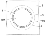
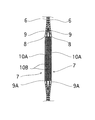
図2は、本実施の形態における破裂板7の断面構造を示し、図3は、破裂板7をバッグ本体6の外方から見た正面図である。破裂板7は、バッグ本体6の所定箇所に形成された開口8をバッグ本体6の内方から覆うシリコーンゴムシート9と、このシリコーンゴムシート9の両面に相対向して貼り付けられる一対の円形の補強シート10A,10Bとからなる。補強シート10A,10Bは、シリコーンゴムシート9よりも強度が大きいアラミド繊維の布から構成され、その外径は開口8の径よりも小さく、開口8縁部との間に1〜10mmの環状の隙間9aが形成されるように貼り付けられる。このように破裂板7は、開口8の周縁から内部にわたって可撓性を有するものとされる。
【0017】
この構成により、飛行体1の着地又は着水時にバッグ本体6に加わる圧縮作用で上昇した内圧を受けて、シリコーンゴムシート9が環状の隙間9aの部位が破裂し、開口8を介してバッグ本体6内のガスが外部へ放出される。そして、着地又は着水時における衝撃をこのエアバッグ51の収縮作用で吸収し、もって、飛行体1およびその搭載機器を上記衝撃から保護する。
【0018】
図1を参照して、本実施の形態では、上述した構成の破裂板7がバッグ本体6の両側方に一対、それぞれバッグ本体6の同一高さ位置に取り付けられ、更に詳しくは、図1Aにおいてバッグ本体6を上下に二分割する分割線Lよりも下側の同一高さレベルに取り付けられている。
【0019】
次に、本実施の形態におけるエアバッグ51を、飛行体1の胴部3及び機首4に設けた収納部12へ収納する方法について説明する。
【0020】
図1Aを参照して、まず、バッグ本体6の接続部6aを胴部3(又は機首4)の収納部12へ気密に接続する。この収納部12には、バッグ本体6を膨張させ、所定のバッグ内圧力(例えば5kPa)で所定の形状(例えば略球状)にするのに必要な圧力ガスボンベが図示せずとも収容されている。そして、吸引口14から図示しない排気ホースを介してバッグ本体6の内部の真空吸引を開始する。
【0021】
次に、図1Bに示すように、分割線Lを境にバッグ本体6の図中上半分を下方へ陥没させるような形態で、分割線Lを折り曲げ線としてバッグ本体6を折り曲げる。そして、図4に示すように破裂板7の内面に対向したバッグ本体6の内面を当該破裂板7の内面に密着あるいは貼り合わせた状態で、バッグ本体6内の真空吸引を続ける。これにより、破裂板7の内面にバッグ本体6の内面が吸着し、破裂板7の強度を高め、破裂板7をしわやねじれ等の不適切な変形から保護し、破裂板7の損傷を防止する。特に、本実施の形態では破裂板7を全体的に可撓性のある構造としているので、上記効果が一層顕著となる。また、圧力ガスの供給によりバッグ本体6を膨張させる際にも破裂板7の損傷が防止され、エアバッグ51の適正な機能が確保される。
【0022】
さて、バッグ本体6内の真空吸引が終了した後は、図1Cに示すようにバッグ本体6の周囲を順に折り畳んで収納部12へ収納し、最後にカバー(蓋部材)13で収納部12を覆う。カバー13はFRP等の強化プラスチックからなるもので、収納部12との間でリベットが打ち込まれることにより固定される。
【0023】
図5及び図6は、上記カバー13のリベット締め工程を示している。本実施の形態では、カバー13に対して所定の荷重を加えながらリベット締めするようにしている。
【0024】
すなわち、図5に示すように受け台56上に収納部12を構成する収納体21を載置し、収納部12内にカバー13の周縁部を嵌入させるとともに、取付治具55を用いてカバー13を収納部12内へ押圧し、その上に重り57を載せて所定の荷重を加える。取付治具55は、受け台56を支持する支持板55aと、この支持板55aの両端にそれぞれ植設されるボルト部55bと、これらボルト部55bに外嵌し上下方向に移動可能な押圧部55cと、各ボルト部55bに螺合するナット部55dとからなり、カバー13の周縁に形成された複数の孔(図示略)を収納体21の周壁に形成された複数の孔(図示略)にそれぞれ合致させた状態で、各ナット部55dを押圧部55cに当接するまで締め付ける。その後、重り57を取り去り、図6に示すように受け台56を介して上記複数の孔を利用してリベット39を締め付ける。
【0025】
なお、飛行体1の着地又は着水の際のエアバッグ51の膨張時は、バッグ本体6に供給されるガスの圧力によりリベット39が分断されることにより、カバー13が機体から除去される。
なおまた、上記所定の荷重でカバー13の孔が収納体21の孔に合致しないときは、飛行体1の着地又は着水の際にエアバッグ51が正常に膨張しないおそれがあるので、図1を参照して説明したバッグ収納作業をし直すようにしている。
【0026】
図7及び図8は、本発明の第2の実施の形態を示している。なお、図において上述の第1の実施の形態と対応する部分については同一の符号を付し、その詳細な説明は省略するものとする。本実施の形態によるエアバッグ52もまた、バッグ本体6と破裂板7とからなり、それぞれ第1の実施の形態と同様な構成を有するが、破裂板7のバッグ本体6に対する取付位置が上述の第1の実施の形態と異なる。すなわち本実施の形態では、破裂板7は、図7Aに示すようにバッグ本体6を上下に分割する分割線Lよりも上方の同一高さレベルに一対、取り付けられている。
【0027】
このように、破裂板7,7が互いに近接した位置に取り付けられるエアバッグ52の収納方法としては、図7B及び図8に示すように各破裂板7,7の内面どうしを互いに密着させ、この状態を保持しながらバッグ本体6の内部を真空吸引して折り畳む。これにより、破裂板7の内面同士が吸着し、破裂板7の強度を高め、破裂板7をしわやねじれ等の不適切な変形から保護し、破裂板7の損傷を防止する。また、圧力ガスの供給によりバッグ本体6を膨張させる際にも破裂板7の損傷を防止し、エアバッグ52の適正な機能を確保する。
【0028】
続いて、図7Cに示すようにバッグ本体6を折り畳んで収納部12へ収納し、カバー13を上述の第1の実施の形態と同様な手法でリベット締めすることにより、エアバッグ52の収納作業が完了する。
【0029】
図9及び図10は、本発明の第3の実施の形態を示している。なお、図において上述の第1の実施の形態と対応する部分については同一の符号を付し、その詳細な説明は省略するものとする。本実施の形態によるエアバッグ53もまた、バッグ本体6と破裂板7とからなり、それぞれ第1の実施の形態と同様な構成を有するが、破裂板7のバッグ本体6に対する取付位置が上述の第1,第2の実施の形態と異なる。すなわち本実施の形態では、破裂板7は、図9Aに示すようにバッグ本体6を上下に分割する分割線Lと同一高さレベルに一対、取り付けられている。
【0030】
このようなエアバッグ53の収納方法としては、図9B及び図10に示すように破裂板7を半分に内方へ180度折り曲げて密着させ、この状態を保持しながらバッグ本体6の内部を真空吸引して折り畳む。これにより、破裂板7の強度を高め、破裂板7をしわやねじれ等の不適切な変形から保護し、破裂板7の損傷を防止する。また、圧力ガスの供給によりバッグ本体6を膨張させる際にも破裂板7の損傷を防止し、エアバッグ53の適正な機能を確保する。
更に本実施の形態によれば、破裂板7自体をも折り曲げているので、破裂板7の大きさに制限されずにエアバッグ53を一層、コンパクトに折り畳んで収納することが可能となる。
【0031】
続いて、図9Cに示すようにバッグ本体6を折り畳んで収納部12へ収納し、カバー13を上述の第1の実施の形態と同様な手法でリベット締めすることにより、エアバッグ53の収納作業が完了する。
【0032】
以上、本発明の各実施の形態について説明したが、勿論、本発明はこれらに限定されることなく、本発明の技術的思想に基づいて種々の変形が可能である。
【0033】
例えば、以上の各実施の形態では、図2及び図3に示す構成を有する破裂板7を例に挙げて説明したが、他の構成を有する破裂板を採用してもよい。例えば図11に示す破裂板17は、バッグ本体16に形成された開口18をバッグ本体16内方からシリコーンゴムシート19で覆ってなるものであるが、本構成の破裂板17によっても、上述の各実施の形態と同様な効果を得ることができる。
【0034】
一方、図12に示す構成の破裂板27は、バッグ本体26の開口28をバッグ本体26外方からアルミ箔29で覆い、その縁部にバッグ本体26の外方および内方から一対の金属製フランジ30A,30Bを接着させてなるものであるが、このような構成の破裂板27もまた、上述の第1,第2の実施の形態に適用することが可能である。
【0035】
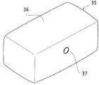
また、以上の各実施の形態においては、その全体的な形状がほぼ球状のエアバッグ51〜53を例に挙げて説明したが、例えば図13に示すような膨張時の形態が直方形状のバッグ本体36と破裂板37とからなるエアバッグ35に対しても、本発明は適用可能である。図14は当該形態のエアバッグ35の収納部32への収納形態を示しており、例えば上述の第1の実施の形態で説明した方法で収納される。
【0036】
更に、被緩衝体として上述した無人飛行体に限らず、例えば上空を飛行する機体から目的地へ向けて落下される救援物資を上記被緩衝体とする衝撃緩衝用エアバッグの収納方法に対しても、本発明は適用可能である。
【0037】
【発明の効果】
以上述べたように、本発明の衝撃緩衝用エアバッグの収納方法によれば、エアバッグの収納時において破裂板に対する不適切な変形を抑制して、当該破裂板の損傷を防止することができるとともに、エアバッグの適切な膨張作用を確保することができる。
【0038】
特に、請求項9の発明によれば、更にコンパクトにエアバッグを折り畳んで収納することが可能となる。
【図面の簡単な説明】
【図1】本発明の第1の実施の形態による衝撃緩衝用エアバッグの収納方法を説明する図であり、Aは折り畳む直前の状態を、Bはバッグ本体を折り畳んで破裂板の内面をバッグ本体の内面へ密着させた状態を、そして、Cは収納部へバッグ本体を収納する状態をそれぞれ示している。
【図2】本発明の第1の実施の形態における破裂板の構成を示す側断面図である。
【図3】図2における[3]−[3]線方向矢視図であり、バッグ本体外方からみた破裂板の正面図である。
【図4】図1Bにおける要部の拡大図である。
【図5】図1Cの続きの工程を示す斜視図であり、エアバッグを収納した収納部へ蓋部材をリベット締めする際の蓋部材に対する加重工程を説明する図である。
【図6】図5の続きの工程を示す斜視図であり、エアバッグを収納した収納部へ蓋部材をリベット締めする工程を説明する図である。
【図7】本発明の第2の実施の形態による衝撃緩衝用エアバッグの収納方法を説明する図であり、Aは折り畳む直前の状態を、Bはバッグ本体を折り畳んで破裂板の内面どうしを相密着させた状態を、そして、Cは収納部へバッグ本体を収納する状態をそれぞれ示している。
【図8】図7Bの要部の拡大図である。
【図9】本発明の第3の実施の形態による衝撃緩衝用エアバッグの収納方法を説明する図であり、Aは折り畳む直前の状態を、Bは破裂板を各々内方へ180度折り曲げて密着させた状態を、そして、Cは収納部へバッグ本体を収納する状態をそれぞれ示している。
【図10】図9Bの要部を示す拡大図である。
【図11】本発明に係る破裂板の構成の変形例を示す側断面図である。
【図12】同他の変形例を示す側断面図である。
【図13】本発明に係るバッグ本体の形状の変形例を示す斜視図である。
【図14】図13に示す形状のバッグ本体の収納形態を示す斜視図である。
【図15】被緩衝体としての無人飛行体の着地又は着水過程を示す図であり、Aはエアバッグを膨張させたときの状態を示す側面図を、Bはその要部の正面図をそれぞれ示している。
【図16】同無人飛行体の着地又は着水時のエアバッグの作用を説明する側面図であり、Aは着時時を、Bは着水時をそれぞれ示している。
【符号の説明】
1 飛行体(被緩衝体)
6 バッグ本体
7 破裂板
8 開口
9 シリコーンゴムシート
10A 補強板
10B 補強板
12 収納部
13 カバー(蓋部材)
51 エアバッグ
52 エアバッグ
53 エアバッグ[0001]
BACKGROUND OF THE INVENTION
The present invention relates to a shock-absorbing airbag storage method that protects, for example, an unmanned air vehicle from an impact upon landing or landing.
[0002]
[Prior art]
FIGS. 15 and 16 show the landing or landing process of the
[0003]
Therefore, when the
[0004]
[Problems to be solved by the invention]
Now, since the storage space of the airbag prepared with respect to the to-be-buffered object such as the
[0005]
That is, when the
[0006]
This invention is made in view of the above-mentioned problem, and makes it a subject to provide the storage method of the airbag for shock buffering which can fold a bag main body, without damaging a rupturable plate.
[0007]
[Means for Solving the Problems]
In solving the above-described problems, the shock-absorbing airbag housing method of the present invention is inflated by supplying pressure gas therein, and protects the buffered body from the impact, and the bag body. An airbag including a thin plate-shaped rupture plate attached to at least one formed opening and ruptured by an increase in internal pressure of the bag body when receiving an impact is stored in a storage portion in the buffered body. In the shock-absorbing airbag storing method, the buffered body is an unmanned flying body, the rupturable plate has flexibility from the periphery of the opening to the inside, and the bag body is vertically moved up and down. the upper bent in the form as is recessed to the lower side boundary dividing line for dividing, in a state in which the inner surface of the rupture disc is brought into close contact with the inner surface of the bag body, the vacuum suction of the inside of the bag body And, after folding the bag body, wherein the housing to the housing portion.
[0008]
According to the present invention, the inside of the bag body is vacuum-sucked while the inner surface of the rupturable plate is in close contact with the inner surface of the bag main body, thereby causing inappropriate deformation (wrinkles, twisting) of the rupturable plate during vacuum suction. Etc.) and avoid damage to the rupture disc. Although there is no particular limitation on the portion of the bag body that is in close contact with the rupturable plate, a method of folding the bag main body in the vicinity of the rupturable plate and then closely contacting the portion of the bag main body facing the inner surface of the rupturable plate is preferable.
[0009]
Here, if the opening peripheral edge of the bag body to which the rupturable plate is attached, including the rupturable plate, has the same thickness as the material constituting the bag main body, it is advantageous in that the mutual adhesion can be enhanced. Moreover, if the structure of the rupturable plate has a flexible structure as a whole, not only the adhesion can be further improved, but also the external stress can be relaxed and the damage prevention effect can be improved.
[0010]
In addition, the shock-absorbing airbag is stored in a bag body that is inflated by pressure gas supplied therein to protect the buffered body from the impact and at least a pair of openings formed in the bag body. And a shock-absorbing airbag storing method for storing an airbag having a thin plate-shaped rupturable plate, which is ruptured by an increase in internal pressure of the bag body when subjected to an impact, in the accommodating portion in the buffered body. The bag body is vacuum-sucked in a state where the inner surfaces of the pair of rupturable plates are in close contact with each other, and the bag body is folded, and then stored in the storage portion.
[0011]
The present invention, the inside of the bag body while being in close contact with inner surfaces of the rupturable plate in the pairs of units obtained by such vacuum suction, thereby improper deformation of the rupture disc at the time of vacuum suction (wrinkles , Torsion, etc.) and avoid rupture disc damage. In particular, the present invention is advantageous when the rupture discs are mounted close to each other.
[0012]
Further, the shock-absorbing airbag is stored in a bag body that is inflated by supplying pressure gas therein and protects the buffered body from the shock, and at least one opening formed in the bag body. In the storage method of the shock-absorbing airbag, the airbag including the thin-plate-shaped rupture plate that is ruptured by an increase in the internal pressure of the bag body when receiving an impact is stored in the storage portion in the buffered body. The rupturable plate has flexibility from the periphery to the inside of the opening, and in the state where the rupturable plate is bent inward by 180 degrees inward, the inside of the bag body is vacuum-sucked to fold the bag body After that, it is stored in the storage unit.
[0013]
In the present invention, the inside of the bag body is vacuum-sucked with the rupturable plate bent inward by 180 degrees inward, thereby causing inappropriate deformation (wrinkles, twisting, etc.) of the rupturable plate during vacuum suction. ) And avoid rupture disc damage. In particular, the present invention is a method of folding the rupturable plate itself as compared with the case of the above invention , so that the bag body can be folded and stored more compactly.
[0014]
DETAILED DESCRIPTION OF THE INVENTION
Embodiments of the present invention will be described below with reference to the drawings. In the following embodiments, a method for storing a substantially spherical shock-absorbing airbag applied to the
[0015]
FIG. 1 shows a method of storing an
[0016]
FIG. 2 shows a cross-sectional structure of the
[0017]
With this configuration, the
[0018]
Referring to FIG. 1, in the present embodiment, a pair of
[0019]
Next, a method of storing the
[0020]
Referring to FIG. 1A, first, the connection portion 6a of the
[0021]
Next, as shown in FIG. 1B, the
[0022]
Now, after the vacuum suction in the
[0023]
5 and 6 show the riveting process of the
[0024]
That is, as shown in FIG. 5, the
[0025]
When the
In addition, when the hole of the
[0026]
7 and 8 show a second embodiment of the present invention. In the figure, portions corresponding to those of the first embodiment described above are denoted by the same reference numerals, and detailed description thereof is omitted. The
[0027]
As described above, as a method of storing the
[0028]
Subsequently, as shown in FIG. 7C, the
[0029]
9 and 10 show a third embodiment of the present invention. In the figure, portions corresponding to those of the first embodiment described above are denoted by the same reference numerals, and detailed description thereof is omitted. The
[0030]
As a method for storing the
Furthermore, according to this embodiment, since the
[0031]
Subsequently, as shown in FIG. 9C, the
[0032]
As mentioned above, although each embodiment of this invention was described, of course, this invention is not limited to these, A various deformation | transformation is possible based on the technical idea of this invention.
[0033]
For example, in each of the above embodiments, the
[0034]
On the other hand, the
[0035]
Further, in each of the above embodiments, the overall shape of the
[0036]
Furthermore, not only the unmanned air vehicle described above as a buffered body, but also for a method of storing an impact cushioning air bag that uses, as a buffered object, relief supplies that are dropped from the aircraft flying over the sky toward the destination. However, the present invention is applicable.
[0037]
【The invention's effect】
As described above, according to the shock absorbing airbag storing method of the present invention, inappropriate deformation of the rupturable plate at the time of storing the airbag can be suppressed, and damage to the rupturable plate can be prevented. At the same time, an appropriate inflating action of the airbag can be ensured.
[0038]
In particular, according to the ninth aspect of the present invention, the airbag can be folded and stored in a more compact manner.
[Brief description of the drawings]
FIGS. 1A and 1B are diagrams for explaining a method of storing an impact cushioning airbag according to a first embodiment of the present invention, in which A is a state immediately before folding, and B is a bag body that is folded to cover the inner surface of a rupturable plate. A state in which the bag body is in close contact with the inner surface of the main body, and a state C in which the bag body is stored in the storage portion are shown.
FIG. 2 is a side sectional view showing the configuration of a rupturable plate in the first embodiment of the present invention.
3 is a front view of the rupturable plate as viewed from the outside of the bag body, as viewed in the direction of arrows [3]-[3] in FIG.
FIG. 4 is an enlarged view of a main part in FIG. 1B.
FIG. 5 is a perspective view showing a continuation process of FIG. 1C, and is a view for explaining a weighting process for the lid member when the lid member is riveted to the storage portion storing the airbag.
6 is a perspective view showing a continuation process of FIG. 5, and is a view for explaining a process of rivet-tightening a lid member to a storage part storing an airbag. FIG.
FIGS. 7A and 7B are diagrams illustrating a method for storing an impact cushioning air bag according to the second embodiment of the present invention, in which A is a state immediately before folding, and B is a state in which the bag body is folded and inner surfaces of the rupturable plates are connected to each other. A state in which the bags are brought into close contact with each other, and C indicates a state in which the bag body is stored in the storage portion.
FIG. 8 is an enlarged view of a main part of FIG. 7B.
FIGS. 9A and 9B are views for explaining a method of storing an impact cushioning airbag according to a third embodiment of the present invention, in which A is a state immediately before folding, and B is a rupture plate folded inward by 180 degrees. The state in which the bag body is in close contact and the state C in which the bag body is stored in the storage portion are shown.
FIG. 10 is an enlarged view showing a main part of FIG. 9B.
FIG. 11 is a side sectional view showing a modification of the structure of the rupturable plate according to the present invention.
FIG. 12 is a side sectional view showing another modification.
FIG. 13 is a perspective view showing a modification of the shape of the bag body according to the present invention.
14 is a perspective view showing a storage form of the bag body having the shape shown in FIG. 13; FIG.
FIG. 15 is a diagram showing a landing or landing process of an unmanned air vehicle as a buffered body, wherein A is a side view showing a state when an airbag is inflated, and B is a front view of the main part thereof. Each is shown.
FIGS. 16A and 16B are side views for explaining the operation of the airbag when the unmanned aerial vehicle lands or lands, in which A indicates when landing and B indicates when landing. FIG.
[Explanation of symbols]
1 Aircraft (buffered body)
6
51
Claims (3)
前記被緩衝体は、無人飛行体であり、
前記破裂板は、前記開口の周縁から内部にわたって可撓性を有しており、
前記バッグ本体を上下に二分割する分割線を境にその上側をその下側へ陥没させるような形態で折り曲げて、前記破裂板の内面を前記バッグ本体の内面に密着させた状態で、前記バッグ本体の内部を真空吸引し、前記バッグ本体を折り畳んだ後、前記収納部へ収納することを特徴とする衝撃緩衝用エアバッグの収納方法。A bag body that is inflated by supplying pressure gas therein and protects the buffered body from impact, and is attached to at least one opening formed in the bag body. In the storage method of the shock-absorbing airbag, the airbag including the thin-plate-shaped rupture plate that is ruptured by an increase in internal pressure is stored in the storage portion in the buffered body.
The buffered body is an unmanned air vehicle,
The rupturable plate has flexibility from the periphery of the opening to the inside,
The bag body is folded in such a manner that the upper side of the bag main body is divided into the lower side with a dividing line dividing the bag main body into two parts, and the inner surface of the rupturable plate is in close contact with the inner surface of the bag main body. A method for storing an air bag for impact buffering, wherein the interior of the main body is vacuum-sucked and the bag main body is folded and then stored in the storage portion.
前記破裂板は、前記開口を塞ぐゴム製シートと、該ゴム製シートの両面に相対向して貼り付けられ、該ゴム製シートより強度が大きく、前記開口の大きさよりも小さい補強シートとからなり、前記開口の周縁との間に環状の隙間が形成されていることを特徴とする衝撃緩衝用エアバッグの収納方法。 A method of storing the shock-absorbing airbag according to claim 1,
The rupturable plate comprises: a rubber sheet that closes the opening; and a reinforcing sheet that is attached to both surfaces of the rubber sheet so as to face each other and has a strength greater than that of the rubber sheet and smaller than the size of the opening. Ri, the method of housing the shock absorbing airbag characterized that you have an annular gap is formed between the periphery of the opening.
前記エアバッグが収納された前記収納部を、所定の荷重を加えながら蓋部材で覆い、前記収納部と前記蓋部材とを互いにリベット締めすることを特徴とする衝撃緩衝用エアバッグの収納方法。 A method of storing the shock-absorbing airbag according to claim 1,
A storage method for an impact cushioning airbag, wherein the storage portion in which the airbag is stored is covered with a lid member while applying a predetermined load, and the storage portion and the lid member are riveted to each other.
Priority Applications (1)
| Application Number | Priority Date | Filing Date | Title |
|---|---|---|---|
| JP2000271004A JP4240260B2 (en) | 2000-09-07 | 2000-09-07 | How to store shock-absorbing airbags |
Applications Claiming Priority (1)
| Application Number | Priority Date | Filing Date | Title |
|---|---|---|---|
| JP2000271004A JP4240260B2 (en) | 2000-09-07 | 2000-09-07 | How to store shock-absorbing airbags |
Publications (2)
| Publication Number | Publication Date |
|---|---|
| JP2002079999A JP2002079999A (en) | 2002-03-19 |
| JP4240260B2 true JP4240260B2 (en) | 2009-03-18 |
Family
ID=18757351
Family Applications (1)
| Application Number | Title | Priority Date | Filing Date |
|---|---|---|---|
| JP2000271004A Expired - Lifetime JP4240260B2 (en) | 2000-09-07 | 2000-09-07 | How to store shock-absorbing airbags |
Country Status (1)
| Country | Link |
|---|---|
| JP (1) | JP4240260B2 (en) |
Families Citing this family (3)
| Publication number | Priority date | Publication date | Assignee | Title |
|---|---|---|---|---|
| EP3253653A4 (en) * | 2015-04-01 | 2018-08-15 | Pham, Ngoc Quy | Powered airbag for aeroplane's vertical fall during an accident |
| WO2018117199A1 (en) * | 2016-12-20 | 2018-06-28 | 日本化薬株式会社 | Airbag device for aircraft |
| CN107697287B (en) * | 2017-10-23 | 2023-05-09 | 天津飞眼无人机科技有限公司 | Control system of water-air dual-purpose vehicle |
-
2000
- 2000-09-07 JP JP2000271004A patent/JP4240260B2/en not_active Expired - Lifetime
Also Published As
| Publication number | Publication date |
|---|---|
| JP2002079999A (en) | 2002-03-19 |
Similar Documents
| Publication | Publication Date | Title |
|---|---|---|
| US5431463A (en) | Air cell bumper device | |
| US2907580A (en) | Pneumatic hold-down for cargo spaces | |
| JP3047226B2 (en) | Lining material | |
| US6042141A (en) | Side restraint assembly | |
| US5819942A (en) | Safety air cushion for a computer | |
| US5242206A (en) | Automotive hail blanket | |
| EP2665649B1 (en) | High efficiency external airbag for crash attenuation | |
| US20080196652A1 (en) | Boat that is provided with floating tubes in a multi-layer design | |
| JPH05147489A (en) | Instrument panel provided with hidden air bag developing door | |
| JPH05501236A (en) | Safety devices for machines with rotating rotors such as helicopters | |
| US5174599A (en) | Steering wheel double air bag protective system | |
| CN107914898B (en) | Carrier rocket sublevel recovery protection landing mechanism, device and working process | |
| KR101301136B1 (en) | Air bag device | |
| CN101743148B (en) | Airbag device | |
| US20170216680A1 (en) | Airbag lung | |
| JP4240260B2 (en) | How to store shock-absorbing airbags | |
| CA2454621A1 (en) | Multi-chambered flotation device | |
| US3773350A (en) | Safety device | |
| JP3362018B2 (en) | airship | |
| CN113264192A (en) | Unmanned aerial vehicle gasbag device | |
| JP2001301551A (en) | Device for protecting vehicle against collision | |
| JP2005178696A (en) | Air bag device | |
| US20030200910A1 (en) | Self inflating marine fender | |
| JP2007314098A (en) | Method for preventing submergence for vehicle and sheet for preventing submergence for vehicle | |
| US8578663B2 (en) | Cover for use with an inflatable modular structure |
Legal Events
| Date | Code | Title | Description |
|---|---|---|---|
| A621 | Written request for application examination |
Free format text: JAPANESE INTERMEDIATE CODE: A621 Effective date: 20070329 |
|
| RD03 | Notification of appointment of power of attorney |
Free format text: JAPANESE INTERMEDIATE CODE: A7423 Effective date: 20071112 |
|
| A977 | Report on retrieval |
Free format text: JAPANESE INTERMEDIATE CODE: A971007 Effective date: 20080825 |
|
| A131 | Notification of reasons for refusal |
Free format text: JAPANESE INTERMEDIATE CODE: A131 Effective date: 20080924 |
|
| A521 | Written amendment |
Free format text: JAPANESE INTERMEDIATE CODE: A523 Effective date: 20081119 |
|
| TRDD | Decision of grant or rejection written | ||
| A01 | Written decision to grant a patent or to grant a registration (utility model) |
Free format text: JAPANESE INTERMEDIATE CODE: A01 Effective date: 20081216 |
|
| A01 | Written decision to grant a patent or to grant a registration (utility model) |
Free format text: JAPANESE INTERMEDIATE CODE: A01 |
|
| A61 | First payment of annual fees (during grant procedure) |
Free format text: JAPANESE INTERMEDIATE CODE: A61 Effective date: 20081217 |
|
| FPAY | Renewal fee payment (event date is renewal date of database) |
Free format text: PAYMENT UNTIL: 20120109 Year of fee payment: 3 |
|
| R150 | Certificate of patent or registration of utility model |
Free format text: JAPANESE INTERMEDIATE CODE: R150 Ref document number: 4240260 Country of ref document: JP Free format text: JAPANESE INTERMEDIATE CODE: R150 |
|
| FPAY | Renewal fee payment (event date is renewal date of database) |
Free format text: PAYMENT UNTIL: 20120109 Year of fee payment: 3 |
|
| S533 | Written request for registration of change of name |
Free format text: JAPANESE INTERMEDIATE CODE: R313533 |
|
| FPAY | Renewal fee payment (event date is renewal date of database) |
Free format text: PAYMENT UNTIL: 20120109 Year of fee payment: 3 |
|
| R350 | Written notification of registration of transfer |
Free format text: JAPANESE INTERMEDIATE CODE: R350 |
|
| FPAY | Renewal fee payment (event date is renewal date of database) |
Free format text: PAYMENT UNTIL: 20120109 Year of fee payment: 3 |
|
| FPAY | Renewal fee payment (event date is renewal date of database) |
Free format text: PAYMENT UNTIL: 20130109 Year of fee payment: 4 |
|
| FPAY | Renewal fee payment (event date is renewal date of database) |
Free format text: PAYMENT UNTIL: 20130109 Year of fee payment: 4 |
|
| FPAY | Renewal fee payment (event date is renewal date of database) |
Free format text: PAYMENT UNTIL: 20140109 Year of fee payment: 5 |
|
| R250 | Receipt of annual fees |
Free format text: JAPANESE INTERMEDIATE CODE: R250 |
|
| S531 | Written request for registration of change of domicile |
Free format text: JAPANESE INTERMEDIATE CODE: R313531 |
|
| R350 | Written notification of registration of transfer |
Free format text: JAPANESE INTERMEDIATE CODE: R350 |
|
| EXPY | Cancellation because of completion of term |