JP4240025B2 - Exhaust purification equipment - Google Patents
Exhaust purification equipment Download PDFInfo
- Publication number
- JP4240025B2 JP4240025B2 JP2005255138A JP2005255138A JP4240025B2 JP 4240025 B2 JP4240025 B2 JP 4240025B2 JP 2005255138 A JP2005255138 A JP 2005255138A JP 2005255138 A JP2005255138 A JP 2005255138A JP 4240025 B2 JP4240025 B2 JP 4240025B2
- Authority
- JP
- Japan
- Prior art keywords
- exhaust
- fuel
- amount
- addition
- basic
- Prior art date
- Legal status (The legal status is an assumption and is not a legal conclusion. Google has not performed a legal analysis and makes no representation as to the accuracy of the status listed.)
- Expired - Fee Related
Links
Images


Classifications
-
- B—PERFORMING OPERATIONS; TRANSPORTING
- B01—PHYSICAL OR CHEMICAL PROCESSES OR APPARATUS IN GENERAL
- B01D—SEPARATION
- B01D53/00—Separation of gases or vapours; Recovering vapours of volatile solvents from gases; Chemical or biological purification of waste gases, e.g. engine exhaust gases, smoke, fumes, flue gases, aerosols
- B01D53/34—Chemical or biological purification of waste gases
- B01D53/92—Chemical or biological purification of waste gases of engine exhaust gases
- B01D53/94—Chemical or biological purification of waste gases of engine exhaust gases by catalytic processes
- B01D53/9495—Controlling the catalytic process
-
- B—PERFORMING OPERATIONS; TRANSPORTING
- B01—PHYSICAL OR CHEMICAL PROCESSES OR APPARATUS IN GENERAL
- B01D—SEPARATION
- B01D53/00—Separation of gases or vapours; Recovering vapours of volatile solvents from gases; Chemical or biological purification of waste gases, e.g. engine exhaust gases, smoke, fumes, flue gases, aerosols
- B01D53/34—Chemical or biological purification of waste gases
- B01D53/92—Chemical or biological purification of waste gases of engine exhaust gases
- B01D53/94—Chemical or biological purification of waste gases of engine exhaust gases by catalytic processes
- B01D53/9445—Simultaneously removing carbon monoxide, hydrocarbons or nitrogen oxides making use of three-way catalysts [TWC] or four-way-catalysts [FWC]
-
- F—MECHANICAL ENGINEERING; LIGHTING; HEATING; WEAPONS; BLASTING
- F01—MACHINES OR ENGINES IN GENERAL; ENGINE PLANTS IN GENERAL; STEAM ENGINES
- F01N—GAS-FLOW SILENCERS OR EXHAUST APPARATUS FOR MACHINES OR ENGINES IN GENERAL; GAS-FLOW SILENCERS OR EXHAUST APPARATUS FOR INTERNAL COMBUSTION ENGINES
- F01N11/00—Monitoring or diagnostic devices for exhaust-gas treatment apparatus, e.g. for catalytic activity
- F01N11/002—Monitoring or diagnostic devices for exhaust-gas treatment apparatus, e.g. for catalytic activity the diagnostic devices measuring or estimating temperature or pressure in, or downstream of the exhaust apparatus
-
- F—MECHANICAL ENGINEERING; LIGHTING; HEATING; WEAPONS; BLASTING
- F01—MACHINES OR ENGINES IN GENERAL; ENGINE PLANTS IN GENERAL; STEAM ENGINES
- F01N—GAS-FLOW SILENCERS OR EXHAUST APPARATUS FOR MACHINES OR ENGINES IN GENERAL; GAS-FLOW SILENCERS OR EXHAUST APPARATUS FOR INTERNAL COMBUSTION ENGINES
- F01N13/00—Exhaust or silencing apparatus characterised by constructional features ; Exhaust or silencing apparatus, or parts thereof, having pertinent characteristics not provided for in, or of interest apart from, groups F01N1/00 - F01N5/00, F01N9/00, F01N11/00
- F01N13/009—Exhaust or silencing apparatus characterised by constructional features ; Exhaust or silencing apparatus, or parts thereof, having pertinent characteristics not provided for in, or of interest apart from, groups F01N1/00 - F01N5/00, F01N9/00, F01N11/00 having two or more separate purifying devices arranged in series
- F01N13/0097—Exhaust or silencing apparatus characterised by constructional features ; Exhaust or silencing apparatus, or parts thereof, having pertinent characteristics not provided for in, or of interest apart from, groups F01N1/00 - F01N5/00, F01N9/00, F01N11/00 having two or more separate purifying devices arranged in series the purifying devices are arranged in a single housing
-
- F—MECHANICAL ENGINEERING; LIGHTING; HEATING; WEAPONS; BLASTING
- F01—MACHINES OR ENGINES IN GENERAL; ENGINE PLANTS IN GENERAL; STEAM ENGINES
- F01N—GAS-FLOW SILENCERS OR EXHAUST APPARATUS FOR MACHINES OR ENGINES IN GENERAL; GAS-FLOW SILENCERS OR EXHAUST APPARATUS FOR INTERNAL COMBUSTION ENGINES
- F01N3/00—Exhaust or silencing apparatus having means for purifying, rendering innocuous, or otherwise treating exhaust
- F01N3/02—Exhaust or silencing apparatus having means for purifying, rendering innocuous, or otherwise treating exhaust for cooling, or for removing solid constituents of, exhaust
- F01N3/021—Exhaust or silencing apparatus having means for purifying, rendering innocuous, or otherwise treating exhaust for cooling, or for removing solid constituents of, exhaust by means of filters
- F01N3/023—Exhaust or silencing apparatus having means for purifying, rendering innocuous, or otherwise treating exhaust for cooling, or for removing solid constituents of, exhaust by means of filters using means for regenerating the filters, e.g. by burning trapped particles
- F01N3/025—Exhaust or silencing apparatus having means for purifying, rendering innocuous, or otherwise treating exhaust for cooling, or for removing solid constituents of, exhaust by means of filters using means for regenerating the filters, e.g. by burning trapped particles using fuel burner or by adding fuel to exhaust
- F01N3/0253—Exhaust or silencing apparatus having means for purifying, rendering innocuous, or otherwise treating exhaust for cooling, or for removing solid constituents of, exhaust by means of filters using means for regenerating the filters, e.g. by burning trapped particles using fuel burner or by adding fuel to exhaust adding fuel to exhaust gases
-
- F—MECHANICAL ENGINEERING; LIGHTING; HEATING; WEAPONS; BLASTING
- F01—MACHINES OR ENGINES IN GENERAL; ENGINE PLANTS IN GENERAL; STEAM ENGINES
- F01N—GAS-FLOW SILENCERS OR EXHAUST APPARATUS FOR MACHINES OR ENGINES IN GENERAL; GAS-FLOW SILENCERS OR EXHAUST APPARATUS FOR INTERNAL COMBUSTION ENGINES
- F01N3/00—Exhaust or silencing apparatus having means for purifying, rendering innocuous, or otherwise treating exhaust
- F01N3/08—Exhaust or silencing apparatus having means for purifying, rendering innocuous, or otherwise treating exhaust for rendering innocuous
- F01N3/0807—Exhaust or silencing apparatus having means for purifying, rendering innocuous, or otherwise treating exhaust for rendering innocuous by using absorbents or adsorbents
- F01N3/0828—Exhaust or silencing apparatus having means for purifying, rendering innocuous, or otherwise treating exhaust for rendering innocuous by using absorbents or adsorbents characterised by the absorbed or adsorbed substances
- F01N3/0842—Nitrogen oxides
-
- F—MECHANICAL ENGINEERING; LIGHTING; HEATING; WEAPONS; BLASTING
- F01—MACHINES OR ENGINES IN GENERAL; ENGINE PLANTS IN GENERAL; STEAM ENGINES
- F01N—GAS-FLOW SILENCERS OR EXHAUST APPARATUS FOR MACHINES OR ENGINES IN GENERAL; GAS-FLOW SILENCERS OR EXHAUST APPARATUS FOR INTERNAL COMBUSTION ENGINES
- F01N3/00—Exhaust or silencing apparatus having means for purifying, rendering innocuous, or otherwise treating exhaust
- F01N3/08—Exhaust or silencing apparatus having means for purifying, rendering innocuous, or otherwise treating exhaust for rendering innocuous
- F01N3/0807—Exhaust or silencing apparatus having means for purifying, rendering innocuous, or otherwise treating exhaust for rendering innocuous by using absorbents or adsorbents
- F01N3/0871—Regulation of absorbents or adsorbents, e.g. purging
-
- F—MECHANICAL ENGINEERING; LIGHTING; HEATING; WEAPONS; BLASTING
- F01—MACHINES OR ENGINES IN GENERAL; ENGINE PLANTS IN GENERAL; STEAM ENGINES
- F01N—GAS-FLOW SILENCERS OR EXHAUST APPARATUS FOR MACHINES OR ENGINES IN GENERAL; GAS-FLOW SILENCERS OR EXHAUST APPARATUS FOR INTERNAL COMBUSTION ENGINES
- F01N3/00—Exhaust or silencing apparatus having means for purifying, rendering innocuous, or otherwise treating exhaust
- F01N3/08—Exhaust or silencing apparatus having means for purifying, rendering innocuous, or otherwise treating exhaust for rendering innocuous
- F01N3/10—Exhaust or silencing apparatus having means for purifying, rendering innocuous, or otherwise treating exhaust for rendering innocuous by thermal or catalytic conversion of noxious components of exhaust
- F01N3/105—General auxiliary catalysts, e.g. upstream or downstream of the main catalyst
- F01N3/106—Auxiliary oxidation catalysts
-
- F—MECHANICAL ENGINEERING; LIGHTING; HEATING; WEAPONS; BLASTING
- F01—MACHINES OR ENGINES IN GENERAL; ENGINE PLANTS IN GENERAL; STEAM ENGINES
- F01N—GAS-FLOW SILENCERS OR EXHAUST APPARATUS FOR MACHINES OR ENGINES IN GENERAL; GAS-FLOW SILENCERS OR EXHAUST APPARATUS FOR INTERNAL COMBUSTION ENGINES
- F01N9/00—Electrical control of exhaust gas treating apparatus
-
- B—PERFORMING OPERATIONS; TRANSPORTING
- B01—PHYSICAL OR CHEMICAL PROCESSES OR APPARATUS IN GENERAL
- B01D—SEPARATION
- B01D2251/00—Reactants
- B01D2251/20—Reductants
- B01D2251/208—Hydrocarbons
-
- F—MECHANICAL ENGINEERING; LIGHTING; HEATING; WEAPONS; BLASTING
- F01—MACHINES OR ENGINES IN GENERAL; ENGINE PLANTS IN GENERAL; STEAM ENGINES
- F01N—GAS-FLOW SILENCERS OR EXHAUST APPARATUS FOR MACHINES OR ENGINES IN GENERAL; GAS-FLOW SILENCERS OR EXHAUST APPARATUS FOR INTERNAL COMBUSTION ENGINES
- F01N2250/00—Combinations of different methods of purification
- F01N2250/02—Combinations of different methods of purification filtering and catalytic conversion
-
- F—MECHANICAL ENGINEERING; LIGHTING; HEATING; WEAPONS; BLASTING
- F01—MACHINES OR ENGINES IN GENERAL; ENGINE PLANTS IN GENERAL; STEAM ENGINES
- F01N—GAS-FLOW SILENCERS OR EXHAUST APPARATUS FOR MACHINES OR ENGINES IN GENERAL; GAS-FLOW SILENCERS OR EXHAUST APPARATUS FOR INTERNAL COMBUSTION ENGINES
- F01N2250/00—Combinations of different methods of purification
- F01N2250/14—Combinations of different methods of purification absorption or adsorption, and filtering
-
- F—MECHANICAL ENGINEERING; LIGHTING; HEATING; WEAPONS; BLASTING
- F01—MACHINES OR ENGINES IN GENERAL; ENGINE PLANTS IN GENERAL; STEAM ENGINES
- F01N—GAS-FLOW SILENCERS OR EXHAUST APPARATUS FOR MACHINES OR ENGINES IN GENERAL; GAS-FLOW SILENCERS OR EXHAUST APPARATUS FOR INTERNAL COMBUSTION ENGINES
- F01N2560/00—Exhaust systems with means for detecting or measuring exhaust gas components or characteristics
- F01N2560/06—Exhaust systems with means for detecting or measuring exhaust gas components or characteristics the means being a temperature sensor
-
- F—MECHANICAL ENGINEERING; LIGHTING; HEATING; WEAPONS; BLASTING
- F01—MACHINES OR ENGINES IN GENERAL; ENGINE PLANTS IN GENERAL; STEAM ENGINES
- F01N—GAS-FLOW SILENCERS OR EXHAUST APPARATUS FOR MACHINES OR ENGINES IN GENERAL; GAS-FLOW SILENCERS OR EXHAUST APPARATUS FOR INTERNAL COMBUSTION ENGINES
- F01N2610/00—Adding substances to exhaust gases
- F01N2610/03—Adding substances to exhaust gases the substance being hydrocarbons, e.g. engine fuel
-
- F—MECHANICAL ENGINEERING; LIGHTING; HEATING; WEAPONS; BLASTING
- F01—MACHINES OR ENGINES IN GENERAL; ENGINE PLANTS IN GENERAL; STEAM ENGINES
- F01N—GAS-FLOW SILENCERS OR EXHAUST APPARATUS FOR MACHINES OR ENGINES IN GENERAL; GAS-FLOW SILENCERS OR EXHAUST APPARATUS FOR INTERNAL COMBUSTION ENGINES
- F01N2610/00—Adding substances to exhaust gases
- F01N2610/14—Arrangements for the supply of substances, e.g. conduits
- F01N2610/1493—Purging the reducing agent out of the conduits or nozzle
-
- F—MECHANICAL ENGINEERING; LIGHTING; HEATING; WEAPONS; BLASTING
- F01—MACHINES OR ENGINES IN GENERAL; ENGINE PLANTS IN GENERAL; STEAM ENGINES
- F01N—GAS-FLOW SILENCERS OR EXHAUST APPARATUS FOR MACHINES OR ENGINES IN GENERAL; GAS-FLOW SILENCERS OR EXHAUST APPARATUS FOR INTERNAL COMBUSTION ENGINES
- F01N2900/00—Details of electrical control or of the monitoring of the exhaust gas treating apparatus
- F01N2900/06—Parameters used for exhaust control or diagnosing
- F01N2900/18—Parameters used for exhaust control or diagnosing said parameters being related to the system for adding a substance into the exhaust
- F01N2900/1806—Properties of reducing agent or dosing system
- F01N2900/1811—Temperature
-
- F—MECHANICAL ENGINEERING; LIGHTING; HEATING; WEAPONS; BLASTING
- F01—MACHINES OR ENGINES IN GENERAL; ENGINE PLANTS IN GENERAL; STEAM ENGINES
- F01N—GAS-FLOW SILENCERS OR EXHAUST APPARATUS FOR MACHINES OR ENGINES IN GENERAL; GAS-FLOW SILENCERS OR EXHAUST APPARATUS FOR INTERNAL COMBUSTION ENGINES
- F01N3/00—Exhaust or silencing apparatus having means for purifying, rendering innocuous, or otherwise treating exhaust
- F01N3/08—Exhaust or silencing apparatus having means for purifying, rendering innocuous, or otherwise treating exhaust for rendering innocuous
- F01N3/0807—Exhaust or silencing apparatus having means for purifying, rendering innocuous, or otherwise treating exhaust for rendering innocuous by using absorbents or adsorbents
- F01N3/0814—Exhaust or silencing apparatus having means for purifying, rendering innocuous, or otherwise treating exhaust for rendering innocuous by using absorbents or adsorbents combined with catalytic converters, e.g. NOx absorption/storage reduction catalysts
-
- F—MECHANICAL ENGINEERING; LIGHTING; HEATING; WEAPONS; BLASTING
- F02—COMBUSTION ENGINES; HOT-GAS OR COMBUSTION-PRODUCT ENGINE PLANTS
- F02M—SUPPLYING COMBUSTION ENGINES IN GENERAL WITH COMBUSTIBLE MIXTURES OR CONSTITUENTS THEREOF
- F02M26/00—Engine-pertinent apparatus for adding exhaust gases to combustion-air, main fuel or fuel-air mixture, e.g. by exhaust gas recirculation [EGR] systems
- F02M26/02—EGR systems specially adapted for supercharged engines
- F02M26/04—EGR systems specially adapted for supercharged engines with a single turbocharger
- F02M26/05—High pressure loops, i.e. wherein recirculated exhaust gas is taken out from the exhaust system upstream of the turbine and reintroduced into the intake system downstream of the compressor
-
- F—MECHANICAL ENGINEERING; LIGHTING; HEATING; WEAPONS; BLASTING
- F02—COMBUSTION ENGINES; HOT-GAS OR COMBUSTION-PRODUCT ENGINE PLANTS
- F02M—SUPPLYING COMBUSTION ENGINES IN GENERAL WITH COMBUSTIBLE MIXTURES OR CONSTITUENTS THEREOF
- F02M26/00—Engine-pertinent apparatus for adding exhaust gases to combustion-air, main fuel or fuel-air mixture, e.g. by exhaust gas recirculation [EGR] systems
- F02M26/13—Arrangement or layout of EGR passages, e.g. in relation to specific engine parts or for incorporation of accessories
- F02M26/22—Arrangement or layout of EGR passages, e.g. in relation to specific engine parts or for incorporation of accessories with coolers in the recirculation passage
- F02M26/23—Layout, e.g. schematics
-
- Y—GENERAL TAGGING OF NEW TECHNOLOGICAL DEVELOPMENTS; GENERAL TAGGING OF CROSS-SECTIONAL TECHNOLOGIES SPANNING OVER SEVERAL SECTIONS OF THE IPC; TECHNICAL SUBJECTS COVERED BY FORMER USPC CROSS-REFERENCE ART COLLECTIONS [XRACs] AND DIGESTS
- Y02—TECHNOLOGIES OR APPLICATIONS FOR MITIGATION OR ADAPTATION AGAINST CLIMATE CHANGE
- Y02T—CLIMATE CHANGE MITIGATION TECHNOLOGIES RELATED TO TRANSPORTATION
- Y02T10/00—Road transport of goods or passengers
- Y02T10/10—Internal combustion engine [ICE] based vehicles
- Y02T10/12—Improving ICE efficiencies
-
- Y—GENERAL TAGGING OF NEW TECHNOLOGICAL DEVELOPMENTS; GENERAL TAGGING OF CROSS-SECTIONAL TECHNOLOGIES SPANNING OVER SEVERAL SECTIONS OF THE IPC; TECHNICAL SUBJECTS COVERED BY FORMER USPC CROSS-REFERENCE ART COLLECTIONS [XRACs] AND DIGESTS
- Y02—TECHNOLOGIES OR APPLICATIONS FOR MITIGATION OR ADAPTATION AGAINST CLIMATE CHANGE
- Y02T—CLIMATE CHANGE MITIGATION TECHNOLOGIES RELATED TO TRANSPORTATION
- Y02T10/00—Road transport of goods or passengers
- Y02T10/10—Internal combustion engine [ICE] based vehicles
- Y02T10/40—Engine management systems
Description
本発明は、内燃機関の排気ガスを触媒にて浄化する装置に関し、さらに詳しくは、排気通路に燃料を添加する燃料添加弁を備えた排気浄化装置に関する。 The present invention relates to an apparatus for purifying exhaust gas of an internal combustion engine with a catalyst, and more particularly to an exhaust purification apparatus provided with a fuel addition valve for adding fuel to an exhaust passage.
一般に、ディーゼルエンジン等のように希薄燃焼を行う内燃機関では、高い空燃比(リーン雰囲気)の混合気を燃焼させる運転領域が全運転領域の大部分を占めている。このため、この種のエンジンの排気通路に、排気ガス中に含まれる窒素酸化物(以下、NOxという)を吸蔵(吸収)するためのNOx吸蔵剤(NOx吸蔵触媒)を配置して排気ガスを浄化するようにしている。 In general, in an internal combustion engine that performs lean combustion, such as a diesel engine, an operation region in which an air-fuel mixture with a high air-fuel ratio (lean atmosphere) is burned occupies most of the entire operation region. For this reason, a NOx storage agent (NOx storage catalyst) for storing (absorbing) nitrogen oxide (hereinafter referred to as NOx) contained in the exhaust gas is disposed in the exhaust passage of this type of engine, and the exhaust gas is disposed. I try to purify it.
このようなNOx吸蔵触媒において、NOx吸蔵量が飽和状態に達した場合には、NOxを還元させてNOx吸蔵触媒を回復させる必要がある。NOxを還元させる方法としては、排気通路のNOx吸蔵触媒の上流にNOx還元剤(軽油等の燃料)を添加することにより、燃料を熱分解させることで炭化水素を発生させ、この炭化水素を還元剤としてNOxの還元を促進させる処理(NOx還元処理)が行われている。 In such a NOx storage catalyst, when the NOx storage amount reaches a saturated state, it is necessary to reduce the NOx and recover the NOx storage catalyst. As a method for reducing NOx, a NOx reducing agent (fuel such as light oil) is added upstream of the NOx occlusion catalyst in the exhaust passage to generate hydrocarbons by thermally decomposing the fuel, and this hydrocarbon is reduced. As the agent, a process for promoting the reduction of NOx (NOx reduction process) is performed.
また、ディーゼルエンジンの排気ガス中には、カーボンを主成分とするパティキュレート(以下、PM(Particulate Matter)という)、SOOT(煤)、SOF(可溶性有機成分:Soluble Organic Fraction)などが含まれており、大気汚染の原因になる。このようなPM等を浄化することを目的として、パティキュレートフィルタをディーゼルエンジンの排気通路に配置し、排気通路を通過する排気ガス中に含まれるPMを捕集することによって、大気中に放出されるエミッションの量を低減する排気浄化装置が知られている。パティキュレートフィルタとしては、例えばDPF(Diesel Particulate Filter)や、DPNR(Diesel Particulate−NOx Reduction system)触媒が用いられている。 In addition, the exhaust gas of diesel engines includes particulates (hereinafter referred to as PM (Particulate Matter)), SOOT (煤), SOF (Soluble Organic Fraction), etc. mainly composed of carbon. Cause air pollution. For the purpose of purifying such PM and the like, a particulate filter is disposed in the exhaust passage of the diesel engine, and the PM contained in the exhaust gas passing through the exhaust passage is collected and released into the atmosphere. There are known exhaust emission control devices that reduce the amount of emissions. As the particulate filter, for example, a DPF (Diesel Particulate Filter) or a DPNR (Diesel Particulate-NOx Reduction system) catalyst is used.
パティキュレートフィルタを用いてPMの捕集を行う場合、捕集したPMの堆積量が多くなってパティキュレートフィルタの詰りが生じると、パティキュレートフィルタを通過する排気の圧力損失が増大し、これに伴うエンジンの排気背圧増大によってエンジン出力低下や燃費の低下が発生する。これを解消する方法として、排気通路(パティキュレートフィルタ上流)に燃料添加を行って排気温度を上昇させることによって、パティキュレートフィルタ上のPMの酸化(燃焼)を促進する処理(PM再生処理)が行われている。 When collecting particulate matter using a particulate filter, if the amount of collected particulate matter increases and the particulate filter becomes clogged, the pressure loss of the exhaust gas passing through the particulate filter increases. Along with this, an increase in engine exhaust back pressure causes a decrease in engine output and fuel consumption. As a method for solving this problem, there is a process (PM regeneration process) that promotes oxidation (combustion) of PM on the particulate filter by adding fuel to the exhaust passage (upstream of the particulate filter) to raise the exhaust temperature. Has been done.
以上のように、触媒の排気浄化作用の低下を抑制するために実施されるNOx還元処理やPM再生処理では、排気通路に燃料添加弁を配置して燃料(還元剤)を排気通路内に供給している。しかし、燃料添加弁の噴孔が排気通路内に露出しているため、排気ガス中に含まれるSOOTやSOFなどの物質が燃料添加弁の噴孔に付着・堆積する。そして、その付着・堆積した物質が高温の排気ガスにさらされることにより変質・固化し、デポジットとなって燃料添加弁の噴孔が閉塞するという問題がある。このような燃料添加弁の詰りを防止する方法として、NOx還元やPM再生時の燃料添加以外のタイミングで、強制的に燃料添加(以下、「詰り防止添加」という)を実施することにより、燃料添加弁の先端温度を下げるという方法がある(例えば、特許文献1参照)。
ところで、詰り防止添加制御は、エンジン回転数と添加量をパラメータとして添加間隔(添加インターバル)を予め設定し、その設定添加間隔に基づいて燃料添加弁の開閉を制御するという方法で実施されている。しかしながら、高地等でのエンジン運転状態では、吸入空気量が平地よりも減少するため排気温度が上昇する。このように環境変化(大気圧変化)により排気温度が上昇した場合、予め設定された設定添加間隔に基づく燃料添加制御では、燃料添加弁の先端温度を所定値(デポジットの生成を抑制できる温度)以下に保つことができなくなる場合があり、燃料添加弁の噴孔閉塞が発生する可能性がある。 By the way, the clogging prevention addition control is performed by a method in which an addition interval (addition interval) is set in advance using the engine speed and the addition amount as parameters, and the opening and closing of the fuel addition valve is controlled based on the set addition interval. . However, when the engine is operating at a high altitude or the like, the exhaust air temperature rises because the amount of intake air is smaller than that on flat ground. In this way, when the exhaust temperature rises due to environmental changes (atmospheric pressure change), the fuel addition control based on a preset addition interval sets the tip temperature of the fuel addition valve to a predetermined value (temperature at which deposit generation can be suppressed). In some cases, it may not be possible to maintain the following, and there is a possibility that the injection hole of the fuel addition valve is blocked.
本発明はそのような実情を考慮してなされたもので、大気圧変化等の環境変化により内燃機関の排気温度が変化しても、排気通路に燃料を添加する燃料添加弁の詰りを抑制することが可能な排気浄化装置を提供することを目的とする。 The present invention has been made in consideration of such circumstances, and suppresses clogging of a fuel addition valve that adds fuel to an exhaust passage even when the exhaust temperature of the internal combustion engine changes due to an environmental change such as a change in atmospheric pressure. It is an object of the present invention to provide an exhaust emission control device that can perform such a process.
本発明は、内燃機関の排気通路に配設された触媒と、前記排気通路に燃料を添加する燃料添加弁とを備えた排気浄化装置において、大気圧をパラメータの一つとして、前記排気通路に排出される排気温度を推定する推定手段と、前記排気通路への燃料の基本添加量を設定するための設定手段と、前記推定手段によって推定される現在の排気温度と前記基本添加量を設定したときの基本排気温度とを用い、前記現在の排気温度から前記基本排気温度を差引いた排気温度変化量が大きいほど前記排気通路への燃料の添加量を増量するように前記燃料添加量を補正するための補正手段とを備えていることを特徴としている。具体的には、前記補正手段は、基本添加間隔及び基本添加時間の少なくともいずれかに、前記排気温度変化量に応じた補正係数を乗じて、前記排気通路への燃料の添加量を補正することを特徴とする。
また、本発明は、内燃機関の排気通路に配設された触媒と、前記排気通路に燃料を添加する燃料添加弁とを備えた排気浄化装置において、大気圧をパラメータの一つとして、前記排気通路に排出される排気温度を推定する推定部と、当該排気浄化装置を制御する制御ユニットとを備えており、前記制御ユニットは、前記排気通路への燃料の基本添加量を設定し、前記推定部によって推定される現在の排気温度と前記基本添加量を設定したときの基本排気温度とを用い、前記現在の排気温度から前記基本排気温度を差引いた排気温度変化量が大きいほど前記排気通路への燃料の添加量を増量するように前記燃料添加量を補正することを特徴としている。より具体的には、前記制御ユニットは、基本添加間隔及び基本添加時間の少なくともいずれかに、前記排気温度変化量に応じた補正係数を乗じて、前記排気通路への燃料の添加量を補正することを特徴とする。
The present invention provides an exhaust gas purification apparatus that includes a catalyst disposed in an exhaust passage of an internal combustion engine and a fuel addition valve that adds fuel to the exhaust passage. Estimating means for estimating the exhaust temperature to be discharged, setting means for setting the basic addition amount of fuel to the exhaust passage, and the current exhaust temperature and the basic addition amount estimated by the estimating means are set The fuel addition amount is corrected so that the fuel addition amount to the exhaust passage is increased as the exhaust temperature change amount obtained by subtracting the basic exhaust temperature from the current exhaust temperature is larger. And a correcting means for the above. Specifically, the correction means corrects the amount of fuel added to the exhaust passage by multiplying at least one of the basic addition interval and the basic addition time by a correction coefficient according to the exhaust temperature change amount. It is characterized by.
The present invention also provides an exhaust gas purification apparatus comprising a catalyst disposed in an exhaust passage of an internal combustion engine and a fuel addition valve for adding fuel to the exhaust passage, wherein the exhaust gas is used with atmospheric pressure as one of the parameters. An estimation unit that estimates an exhaust gas temperature discharged to the passage; and a control unit that controls the exhaust gas purification device, wherein the control unit sets a basic addition amount of fuel to the exhaust passage, and the estimation unit The exhaust gas temperature change amount obtained by subtracting the basic exhaust temperature from the current exhaust temperature is increased to the exhaust passage using the current exhaust temperature estimated by the unit and the basic exhaust temperature when the basic addition amount is set . The fuel addition amount is corrected so as to increase the fuel addition amount. More specifically, the control unit corrects the amount of fuel added to the exhaust passage by multiplying at least one of the basic addition interval and the basic addition time by a correction coefficient according to the exhaust temperature change amount. It is characterized by that.
本発明によれば、高地などにおいて排気温度が上昇したときには、その排気温度の上昇に応じて、例えば燃料の添加間隔を補正することにより、燃料添加量を多くすることができるので、燃料添加弁の先端部の温度上昇を抑制することができる。これによって、燃料添加弁の先端温度を所定値(デポジットの生成を抑制できる温度)以下に保つことが可能となり、燃料添加弁の噴孔がデポジットにて閉塞されるという問題を回避することができる。 According to the present invention, when the exhaust gas temperature rises at high altitudes or the like, the fuel addition amount can be increased by correcting the fuel addition interval, for example, in accordance with the increase in the exhaust gas temperature. Temperature rise at the tip of the can be suppressed. As a result, the tip temperature of the fuel addition valve can be kept below a predetermined value (a temperature at which deposit generation can be suppressed), and the problem that the nozzle hole of the fuel addition valve is blocked by the deposit can be avoided. .
本発明において、添加量補正に用いる排気温度は、エンジン回転数、吸気温度及び大気圧等のパラメータから推定した推定値であってもよいし、また、燃料添加弁が配設されている近傍の排気温度(例えばターボチャージャの上流側の排気温度)を検出する排気温センサを設置し、そのセンサ出力から排気温度を得るようにしてもよい。 In the present invention, the exhaust temperature used for the addition amount correction may be an estimated value estimated from parameters such as the engine speed, the intake air temperature, and the atmospheric pressure, or in the vicinity where the fuel addition valve is provided. An exhaust temperature sensor that detects the exhaust temperature (for example, the exhaust temperature upstream of the turbocharger) may be installed, and the exhaust temperature may be obtained from the sensor output.
本発明によれば、大気圧変化等の環境変化により内燃機関の排気温度が変化しても、排気通路に燃料を添加する燃料添加弁の詰りを抑制することができる。 According to the present invention, even when the exhaust temperature of the internal combustion engine changes due to an environmental change such as a change in atmospheric pressure, the clogging of the fuel addition valve that adds fuel to the exhaust passage can be suppressed.
以下、本発明の実施形態を図面に基づいて説明する。 Hereinafter, embodiments of the present invention will be described with reference to the drawings.
−エンジン−
本発明の燃料添加装置を適用するディーゼルエンジンの概略構成を図1を参照して説明する。
-Engine-
A schematic configuration of a diesel engine to which the fuel addition apparatus of the present invention is applied will be described with reference to FIG.
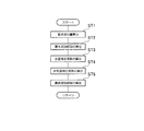
この例のディーゼルエンジン1(以下、「エンジン1」という)は、例えばコモンレール式筒内直噴4気筒エンジンであって、燃料供給系2、燃焼室3、吸気系6、及び、排気系7などを主要部として構成されている。
A diesel engine 1 (hereinafter referred to as “
燃料供給系2は、サプライポンプ21、コモンレール22、インジェクタ(燃料噴射弁)23、遮断弁24、燃料添加弁25、機関燃料通路26、及び、添加燃料通路27などを備えている。
The
サプライポンプ21は、燃料タンクから燃料を汲み上げ、この汲み上げた燃料を高圧にした後、機関燃料通路26を介してコモンレール22に供給する。コモンレール22は、サプライポンプ21から供給された高圧燃料を所定圧力に保持(蓄圧)する蓄圧室としての機能を有し、この蓄圧した燃料を各インジェクタ23に分配する。インジェクタ23は所定電圧が印加されたときに開弁して、燃焼室3内に燃料を噴射供給する電磁駆動式の開閉弁である。
The
また、サプライポンプ21は、燃料タンクから汲み上げた燃料の一部を、添加燃料通路27を介して燃料添加弁25に供給する。燃料添加弁25は、所定電圧が印加されたときに開弁して、排気系7(排気ポート71から排気マニホールド72)に燃料を添加する電磁駆動式の開閉弁である。遮断弁24は、緊急時に添加燃料通路27を遮断して燃料供給を停止する。
Further, the
吸気系6は、シリンダヘッドに形成された吸気ポートに接続される吸気マニホールド63を備え、この吸気マニホールド63に、吸気通路を構成する吸気管64が接続されている。また、吸気通路には、上流側から順にエアクリーナ65、エアフローメータ32、スロットル弁62が配設されている。エアフローメータ32は、エアクリーナ65を介して吸気通路に流入される空気量に応じた電気信号を出力するようになっている。
The
排気系7は、シリンダヘッドに形成された排気ポート71に接続される排気マニホールド72を備え、この排気マニホールド72に、排気通路を構成する排気管73,74が接続されている。また、この排気通路には触媒装置4が配設されている。
The
触媒装置4は、NOx吸蔵還元型触媒4aとDPNR触媒4bとを備えている。NOx吸蔵還元型触媒4aは、排気中に多量の酸素が存在している状態においてはNOxを吸蔵し、排気中の酸素濃度が低く、かつ還元成分(例えば燃料の未燃成分(HC))が多量に存在している状態においてはNOxをNO2もしくはNOに還元して放出する。NO2やNOとして放出されたNOxは、排気中のHCやCOと速やかに反応することによってさらに還元されてN2となる。また、HCやCOは、NO2やNOを還元することで、自身は酸化されてH2OやCO2となる。
The
DPNR触媒4bは、例えば多孔質セラミック構造体にNOx吸蔵還元型触媒を担持させたものであり、排気ガス中のPMは多孔質の壁を通過する際に捕集される。また、排気ガスの空燃比がリーンの場合、排気ガス中のNOxはNOx吸蔵還元型触媒に吸蔵され、空燃比がリッチになると吸蔵したNOxは還元・放出される。さらに、DPNR触媒4bには、捕集したPMを酸化・燃焼する触媒(例えば白金等の貴金属を主成分とする酸化触媒)が担持されている。
The
以上の触媒装置4、燃料添加弁25、添加燃料通路27、遮断弁24、及び、燃料添加弁25の開閉制御を実行するECU(電子制御ユニット)100等によって排気浄化装置が構成されている。
The above-described
エンジン1には、ターボチャージャ(過給機)5が設けられている。このターボチャージャ5は、タービンシャフト5aを介して連結されたタービンホイール5b及びコンプレッサホイール5cを備えている。コンプレッサホイール5cは吸気管64内部に臨んで配置され、タービンホイール5bは排気管73内部に臨んで配置されている。このようなターボチャージャ5は、タービンホイール5bが受ける排気流(排気圧)を利用してコンプレッサホイール5cを回転させることにより吸入空気を過給する。この例のターボチャージャ5は、可変ノズル式ターボチャージャであって、タービンホイール5b側に可変ノズルベーン機構5dが設けられており、この可変ノズルベーン機構5dの開度を調整することにより、エンジン1の過給圧を調整することができる。
The
吸気系6の吸気管64には、ターボチャージャ5での過給によって昇温した吸入空気を強制冷却するためのインタークーラ61が設けられている。このインタークーラ61よりも更に下流側にスロットル弁62が設けられている。スロットル弁62は、その開度を無段階に調整することが可能な電子制御式の開閉弁であり、所定の条件下において吸入空気の流路面積を絞り、この吸入空気の供給量を調整(低減)する機能を有している。
An
また、エンジン1には、吸気系6と排気系7とを接続するEGR通路(排気還流通路)8が設けられている。EGR通路8は、排気の一部を適宜吸気系6に還流させて燃焼室3へ再度供給することにより燃焼温度を低下させ、これによってNOx発生量を低減させるものである。また、EGR通路8には、EGR弁81と、EGR通路8を通過(還流)する排気を冷却するためのEGRクーラ82とが設けられており、EGR弁81の開度を調整することにより、排気系7から吸気系6に導入されるEGR量(排気還流量)を調整することができる。
Further, the
−センサ類−
エンジン1の各部位には、各種センサが取り付けられており、それぞれの部位の環境条件や、エンジン1の運転状態に関する信号を出力する。
-Sensors-
Various sensors are attached to each part of the
例えば、エアフローメータ32は、吸気系6内のスロットル弁62上流において吸入空気の流量(吸気量)に応じた検出信号を出力する。吸気温センサ33は、吸気マニホールド63に配置され、吸入空気温度に応じた検出信号を出力する。吸気圧センサ34は、吸気マニホールド63に配置され、吸入空気圧力に応じた検出信号を出力する。A/F(空燃比)センサ35は、排気系7の触媒装置4の下流において排気中の酸素濃度に応じて連続的に変化する検出信号を出力する。排気温センサ36は、同じく排気系7の触媒装置4の下流において排気ガスの温度(排気温度)に応じた検出信号を出力する。レール圧センサ37はコモンレール22内に蓄えられている燃料の圧力に応じた検出信号を出力する。燃圧センサ38は、添加燃料通路27内を流通する燃料の圧力(燃圧)に応じた検出信号を出力する。
For example, the
−ECU−
ECU100は、図2に示すように、CPU101、ROM102、RAM103及びバックアップRAM104などを備えている。ROM102は、各種制御プログラムや、それら各種制御プログラムを実行する際に参照されるマップ等が記憶されている。CPU101は、ROM102に記憶された各種制御プログラムやマップに基づいて各種の演算処理を実行する。また、RAM103は、CPU101での演算結果や各センサから入力されたデータ等を一時的に記憶するメモリであり、バックアップRAM104は、例えばエンジン1の停止時にその保存すべきデータ等を記憶する不揮発性のメモリである。
-ECU-
As shown in FIG. 2, the
以上のROM102、CPU101、RAM103及びバックアップRAM104は、バス107を介して互いに接続されるとともに、外部入力回路105及び外部出力回路106と接続されている。
The
外部入力回路105には、上記したエアフローメータ32、吸気温センサ33、吸気圧センサ34、A/Fセンサ35、排気温センサ36、レール圧センサ37、燃圧センサ38が接続されており、さらに、エンジン1の冷却水温に応じた検出信号を出力する水温センサ31、アクセルペダルへの踏み込み量に応じた検出信号を出力するアクセル開度センサ39、及び、エンジン1の出力軸(クランクシャフト)が一定角度回転する毎に検出信号(パルス)を出力するクランクポジションセンサ40などが接続されている。一方、外部出力回路106には、インジェクタ23、遮断弁24、燃料添加弁25、可変ノズルベーン機構5d、スロットル弁62、及び、EGR弁81などが接続されている。
The
そして、ECU100は、上記した各種センサの出力に基づいて、エンジン1の各種制御を実行する。さらに、ECU100は、下記のPM再生制御、及び、詰り防止添加制御時の添加間隔補正処理を実行する。
The
−PM再生制御−
まず、ECU100は、DPNR触媒4bへのPMの堆積量を推定している。PM堆積量を推定する方法としては、例えば、エンジン1の運転状態(例えば、排気温度、燃料噴射量、エンジン回転数等)に応じたPM付着量を予め実験等により求めてマップ化しておき、このマップにより求められるPM付着量を積算してPMの堆積量とする方法や、車両走行距離もしくは走行時間に応じてPMの堆積量を推定する方法、あるいは、触媒装置4にDPNR触媒4bの上流側圧力と下流側圧力との差圧を検出する差圧センサを設け、そのセンサ出力に基づいてDPNR触媒4bに捕集されたPMの堆積量を推定する方法などが挙げられる。
-PM regeneration control-
First, the
そして、ECU100は、PM推定量が所定の基準値(限界堆積量)以上となったときにDPNR触媒4bの再生時期であると判定してPM再生制御を実行する。具体的には、クランクポジションセンサ40の出力から読み込んだエンジン回転数に基づいて、予め実験等により作成されたマップを参照して燃料の要求添加量及び添加間隔を算出し、その算出結果に応じて燃料添加弁25の開閉を制御して、排気系7に燃料添加を断続的に繰り返す。このような燃料添加により、DPNR触媒4bの触媒床温が上昇し、DPNR触媒4bに堆積しているPMが酸化され、H2OやCO2となって排出する。
Then, the
なお、ECU100は、以上のPM再生制御のほか、S被毒回復制御やNOx還元制御を実行する場合もある。S被毒回復制御とは、燃料添加弁25からの燃料添加を断続的に繰り返して触媒床温を高温化するとともに、排気ガスの空燃比をストイキあるいはリッチとし、NOx吸蔵還元型触媒4a及びDPNR触媒4b内のNOx吸蔵還元型触媒から硫黄分を放出させる制御である。また、NOx還元制御は、燃料添加弁25からの間欠的な燃料添加により、NOx吸蔵還元型触媒4a及びDPNR触媒4b内のNOx吸蔵還元型触媒に吸蔵されたNOxを、N2、CO2及びH2Oに還元して放出する制御である。
In addition to the above PM regeneration control, the
これらのPM再生制御、S被毒回復制御及びNOx還元制御は、それぞれの実行要求があったときに行われるが、各制御の実行が重なったときには、PM再生制御→S被毒回復制御→NOx還元制御の順で優先して行われる。 These PM regeneration control, S poison recovery control and NOx reduction control are performed when there is a request for execution of each, but when the execution of each control overlaps, PM regeneration control → S poison recovery control → NOx. Prioritized in the order of reduction control.
−添加間隔補正処理−
まず、上記したように、高地等でのエンジン運転状態では、吸入空気量が平地よりも減少するため排気温度が上昇する。このように環境変化(大気圧変化)により排気温度が上昇した場合、予め設定された設定添加間隔に基づく詰り防止添加制御では、燃料添加弁25の先端温度を所定値(デポジットの生成を抑制できる温度)以下に保つことができなくなる場合があり、燃料添加弁の噴孔閉塞が発生する可能性がある。これを解消するため、この実施形態では、詰り防止添加制御を実行する際に、大気圧の変化による排気温度の変化に応じて燃料の添加間隔を補正して燃料添加弁25の先端部の温度上昇を抑制する点に特徴がある。
-Addition interval correction processing-
First, as described above, when the engine is operating at high altitude or the like, the exhaust air temperature rises because the intake air amount decreases from the level. In this way, when the exhaust gas temperature rises due to environmental changes (atmospheric pressure changes), the clogging prevention addition control based on a preset addition interval can reduce the tip temperature of the
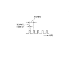
その添加間隔補正処理の具体的な例を図3のフローチャートを参照しながら説明する。この添加間隔補正処理はECU100が実行する処理である。なお、この補正処理ルーチンは所定時間周期で繰り返し実行される。
A specific example of the addition interval correction process will be described with reference to the flowchart of FIG. This addition interval correction process is a process executed by the
まず、ステップST1において、クランクポジションセンサ40の出力からエンジン回転数Neを読み込み、そのエンジン回転数Neに基づいてマップを参照して要求添加量Qを算出する。要求添加量Qを算出するマップは、エンジン回転数Neと要求添加量Qとの関係を予め実験・計算等によって求め、それらの関係をマップ化したものであり、ECU100のROM102内に予め記憶されている。
First, in step ST1, the engine speed Ne is read from the output of the
ステップST2では、要求添加量Qとエンジン回転数Neに基づいて図4のマップを参照して燃料の基本添加間隔Tb(図7参照)を算出する。基本添加間隔算出マップは、要求添加量Q及びエンジン回転数Neと基本添加間隔Tbとの関係を予め実験・計算等によって求め、それらの関係をマップ化したものであり、ECU100のROM102内に予め記憶されている。また、ステップST2において、基本添加間隔Tbを算出したときの基本排気温度(燃料添加弁25の周辺温度)を取得しておく。
In step ST2, the fuel basic addition interval Tb (see FIG. 7) is calculated with reference to the map of FIG. 4 based on the required addition amount Q and the engine speed Ne. The basic addition interval calculation map is a map in which the relationship between the required addition amount Q and the engine speed Ne and the basic addition interval Tb is obtained in advance through experiments and calculations, and is mapped into the
ステップST3では、水温センサ31の出力から冷却水温を読み込み、その冷却水温に基づいて図5のマップを参照して水温補正係数αを算出する。水温補正係数マップは、冷却水温と水温補正係数αとの関係を予め実験・計算等によって求め、それらの関係をマップ化したものであり、ECU100のROM102内に予め記憶されている。
In step ST3, the coolant temperature is read from the output of the
ステップST4では、上記ステップST2で求めた基本排気温度と現在の排気温度との差(排気温度変化量ΔTh)に基づいて図6のマップを参照して排気温補正係数βを算出する。排気温補正係数マップは、排気温度変化量ΔThと排気温補正係数βとの関係を予め実験・計算等によって求め、それらの関係をマップ化したものであり、ECU100のROM102内に予め記憶されている。排気温補正係数βは、排気温度変化量ΔThが大きいほど小さい値となるように設定されており、排気温補正係数βが小さくなるほど燃料の添加間隔が短縮される。
In step ST4, the exhaust temperature correction coefficient β is calculated with reference to the map of FIG. 6 based on the difference (exhaust temperature change amount ΔTh) between the basic exhaust temperature obtained in step ST2 and the current exhaust temperature. The exhaust temperature correction coefficient map is obtained by previously obtaining the relationship between the exhaust temperature change amount ΔTh and the exhaust temperature correction coefficient β by experiments and calculations, and mapping the relationship, and is stored in the
なお、排気温度(燃料添加弁25の周辺温度)は、エンジン回転数Ne、吸気温度及び大気圧等をパラメータとする排気温度算出マップを、予め実験・計算等によって作成してECU100のROM102に記憶しておき、その排気温度算出マップを参照して算出するようにしてもよいし、また、例えばターボチャージャ5の上流側の排気温度を検出するターボ前排気温センサを設置し、そのセンサ出力から排気温度を得るようにしてもよい。
As for the exhaust temperature (ambient temperature of the fuel addition valve 25), an exhaust temperature calculation map using the engine speed Ne, the intake air temperature, the atmospheric pressure, and the like as parameters is created in advance through experiments and calculations and stored in the
そして、ステップST6において、以上のようにして算出した基本添加間隔Tb、水温補正係数α及び排気温補正係数βを用いて、最終添加間隔を、演算式[最終添加間隔=基本添加間隔Tb×水温補正係数α×排気温補正係数β]に基づいて算出して、このルーチンを終了する。 In step ST6, using the basic addition interval Tb, the water temperature correction coefficient α, and the exhaust temperature correction coefficient β calculated as described above, the final addition interval is calculated using the equation [final addition interval = basic addition interval Tb × water temperature. The correction coefficient α × exhaust temperature correction coefficient β] is calculated, and this routine ends.
以上の添加間隔補正処理によれば、基本添加間隔を設定したときの基本排気温度に対する現在の排気温度の変化量に基づいて、その排気温度の変化量が大きいほど、燃料の添加間隔を短くするように補正しているので、高地などにおいて排気温度が上昇したときには、その排気温度上昇に応じて燃料の添加間隔が短縮補正され、燃料の添加量が増量補正される。これによって燃料添加弁25の先端部の温度上昇を抑制することができ、燃料添加弁25の先端温度を所定値(デポジットの生成を抑制できる温度)以下に保つことが可能になる。その結果として、燃料添加弁25の噴孔がデポジットにて閉塞されるという問題を回避することができる。
According to the above addition interval correction processing, based on the current exhaust temperature change amount with respect to the basic exhaust temperature when the basic addition interval is set, the larger the exhaust temperature change amount, the shorter the fuel addition interval. Thus, when the exhaust gas temperature rises at high altitudes or the like, the fuel addition interval is shortened and the fuel addition amount is corrected to increase in accordance with the exhaust gas temperature rise. As a result, a temperature rise at the tip of the
−他の実施形態−
以上の例では、基本添加間隔Tbに排気温補正係数βを乗じて燃料の添加量を補正しているが、これに替えて、1回当たり基本添加時間(図7参照)に排気温補正係数を乗じて燃料の添加量を増量補正するようにしてもよい。なお、1回当たり基本添加時間を補正する場合、排気温補正係数は、排気温度変化量ΔThが大きくなるほど大きな値となるように設定する。
-Other embodiments-
In the above example, the fuel addition amount is corrected by multiplying the basic addition interval Tb by the exhaust temperature correction coefficient β, but instead, the exhaust temperature correction coefficient is calculated at the basic addition time (see FIG. 7) per time. May be added to correct the amount of fuel addition. When correcting the basic addition time per time, the exhaust temperature correction coefficient is set so as to increase as the exhaust temperature change amount ΔTh increases.
以上の例では、本発明の排気浄化装置を筒内直噴4気筒ディーゼルエンジンに適用した例を示したが、本発明はこれに限られることなく、例えば筒内直噴6気筒ディーゼルエンジンなど他の任意の気筒数のディーゼルエンジンにも適用できる。また、筒内直噴ディーゼルエンジンに限られることなく、他のタイプのディーゼルエンジンにも本発明を適用することは可能である。また、車両用に限らず、その他の用途に使用されるエンジンにも適用可能である。 In the above example, the exhaust purification apparatus of the present invention is applied to an in-cylinder direct injection 4-cylinder diesel engine. However, the present invention is not limited to this, and other examples such as an in-cylinder direct injection 6-cylinder diesel engine, etc. It can also be applied to diesel engines with any number of cylinders. Further, the present invention is not limited to an in-cylinder direct injection diesel engine, but can be applied to other types of diesel engines. Moreover, it is applicable not only for vehicles but also for engines used for other purposes.
以上の例では、触媒装置4として、NOx吸蔵還元型触媒4a及びDPNR触媒4bを備えたものとしたが、NOx吸蔵還元型触媒4a或いは酸化触媒、及びDPFを備えたものとしてもよい。
In the above example, the
1 エンジン(内燃機関)
2 燃料供給系
21 サプライポンプ
22 コモンレール
24 遮断弁
23 インジェクタ
25 燃料添加弁
27 添加燃料通路
4 触媒装置
4a NOx吸蔵還元型触媒
4b DPNR触媒
6 吸気系
7 排気系
40 クランクポジションセンサ
100 ECU
1 engine (internal combustion engine)
DESCRIPTION OF
Claims (4)
大気圧をパラメータの一つとして、前記排気通路に排出される排気温度を推定する推定手段と、
前記排気通路への燃料の基本添加量を設定するための設定手段と、
前記推定手段によって推定される現在の排気温度と、前記基本添加量を設定したときの基本排気温度とを用い、前記現在の排気温度から前記基本排気温度を差引いた排気温度変化量が大きいほど前記排気通路への燃料の添加量を増量するように前記燃料添加量を補正するための補正手段とを備えていることを特徴とする排気浄化装置。 In an exhaust purification device comprising a catalyst disposed in an exhaust passage of an internal combustion engine and a fuel addition valve for adding fuel to the exhaust passage,
Estimating means for estimating the exhaust temperature discharged into the exhaust passage, using atmospheric pressure as one of the parameters;
Setting means for setting the basic amount of fuel added to the exhaust passage;
Using the current exhaust temperature estimated by the estimating means and the basic exhaust temperature when the basic addition amount is set, the larger the exhaust temperature change amount obtained by subtracting the basic exhaust temperature from the current exhaust temperature, the larger the An exhaust emission control device comprising: correction means for correcting the fuel addition amount so as to increase the fuel addition amount to the exhaust passage.
前記補正手段は、基本添加間隔及び基本添加時間の少なくともいずれかに、前記排気温度変化量に応じた補正係数を乗じて、前記排気通路への燃料の添加量を補正することを特徴とする排気浄化装置。 The exhaust emission control device according to claim 1,
The correction means corrects the amount of fuel added to the exhaust passage by multiplying at least one of a basic addition interval and a basic addition time by a correction coefficient corresponding to the exhaust temperature change amount. Purification equipment.
大気圧をパラメータの一つとして、前記排気通路に排出される排気温度を推定する推定部と、当該排気浄化装置を制御する制御ユニットとを備え、
前記制御ユニットは、前記排気通路への燃料の基本添加量を設定し、前記推定部によって推定される現在の排気温度と、前記基本添加量を設定したときの基本排気温度とを用い、前記現在の排気温度から前記基本排気温度を差引いた排気温度変化量が大きいほど前記排気通路への燃料の添加量を増量するように前記燃料添加量を補正することを特徴とする排気浄化装置。 In an exhaust purification device comprising a catalyst disposed in an exhaust passage of an internal combustion engine and a fuel addition valve for adding fuel to the exhaust passage,
With an atmospheric pressure as one of the parameters, an estimation unit that estimates the exhaust temperature discharged into the exhaust passage, and a control unit that controls the exhaust purification device,
The control unit sets a basic addition amount of fuel to the exhaust passage, uses a current exhaust temperature estimated by the estimation unit, and a basic exhaust temperature when the basic addition amount is set, and An exhaust emission control device that corrects the fuel addition amount so that the amount of fuel addition to the exhaust passage increases as the exhaust temperature change amount obtained by subtracting the basic exhaust temperature from the exhaust temperature of the exhaust gas increases.
前記制御ユニットは、基本添加間隔及び基本添加時間の少なくともいずれかに、前記排気温度変化量に応じた補正係数を乗じて、前記排気通路への燃料の添加量を補正することを特徴とする排気浄化装置。 The exhaust emission control device according to claim 3,
The control unit corrects the amount of fuel added to the exhaust passage by multiplying at least one of a basic addition interval and a basic addition time by a correction coefficient corresponding to the exhaust temperature change amount. Purification equipment.
Priority Applications (4)
| Application Number | Priority Date | Filing Date | Title |
|---|---|---|---|
| JP2005255138A JP4240025B2 (en) | 2005-09-02 | 2005-09-02 | Exhaust purification equipment |
| PCT/JP2006/317392 WO2007026904A1 (en) | 2005-09-02 | 2006-08-28 | Exhaust gas purification device |
| EP06783164.4A EP1933014B1 (en) | 2005-09-02 | 2006-08-28 | Exhaust gas purification device |
| US12/065,237 US8181447B2 (en) | 2005-09-02 | 2006-08-28 | Exhaust gas purification device |
Applications Claiming Priority (1)
| Application Number | Priority Date | Filing Date | Title |
|---|---|---|---|
| JP2005255138A JP4240025B2 (en) | 2005-09-02 | 2005-09-02 | Exhaust purification equipment |
Publications (2)
| Publication Number | Publication Date |
|---|---|
| JP2007064183A JP2007064183A (en) | 2007-03-15 |
| JP4240025B2 true JP4240025B2 (en) | 2009-03-18 |
Family
ID=37808988
Family Applications (1)
| Application Number | Title | Priority Date | Filing Date |
|---|---|---|---|
| JP2005255138A Expired - Fee Related JP4240025B2 (en) | 2005-09-02 | 2005-09-02 | Exhaust purification equipment |
Country Status (4)
| Country | Link |
|---|---|
| US (1) | US8181447B2 (en) |
| EP (1) | EP1933014B1 (en) |
| JP (1) | JP4240025B2 (en) |
| WO (1) | WO2007026904A1 (en) |
Families Citing this family (13)
| Publication number | Priority date | Publication date | Assignee | Title |
|---|---|---|---|---|
| ITMI20071123A1 (en) | 2007-06-01 | 2008-12-02 | Bosch Gmbh Robert | REGENERATION METHOD OF THE PARTICULATE FILTER OF AN INTERNAL COMBUSTION ENGINE AND INTERNAL COMBUSTION ENGINE THAT CAN IMPLEMENT THIS METHOD |
| JP2008309080A (en) * | 2007-06-15 | 2008-12-25 | Denso Corp | Exhaust emission control device for internal combustion engine |
| JP4910930B2 (en) * | 2007-07-27 | 2012-04-04 | トヨタ自動車株式会社 | Exhaust gas purification device for internal combustion engine |
| JP4453739B2 (en) | 2007-10-24 | 2010-04-21 | トヨタ自動車株式会社 | Control method of addition valve |
| JP5142048B2 (en) * | 2008-04-08 | 2013-02-13 | 株式会社デンソー | Exhaust gas purification device for internal combustion engine |
| DK2321506T3 (en) * | 2008-07-07 | 2013-03-18 | Emitec Denmark As | DOSING SYSTEM FOR USE IN A EXHAUST ENGINE EXHAUST SYSTEM |
| SE535931C2 (en) * | 2010-06-21 | 2013-02-26 | Scania Cv Ab | Method and apparatus for avoiding overheating of a dosing unit in an HC dosing system |
| SE536316C2 (en) * | 2010-06-21 | 2013-08-20 | Scania Cv Ab | Method and apparatus for removing fuel from a metering unit of an HC metering system |
| SE536318C2 (en) * | 2010-06-21 | 2013-08-20 | Scania Cv Ab | Method and apparatus for removing reducing agent from a metering unit of an SCR system |
| JP5915516B2 (en) | 2012-12-25 | 2016-05-11 | トヨタ自動車株式会社 | Exhaust gas purification device for internal combustion engine |
| JP6161197B2 (en) * | 2013-07-18 | 2017-07-12 | ボッシュ株式会社 | Exhaust pipe fuel injection device and exhaust pipe fuel injection method |
| GB2529781A (en) * | 2015-12-01 | 2016-03-02 | Gm Global Tech Operations Inc | Method of detecting a clogging of a fuel injector in an internal combustion engine |
| CN106839273B (en) * | 2016-12-30 | 2019-07-30 | 美的集团股份有限公司 | Air cleaning facility and its control method, control system and server |
Family Cites Families (15)
| Publication number | Priority date | Publication date | Assignee | Title |
|---|---|---|---|---|
| JPH051837U (en) | 1991-06-26 | 1993-01-14 | 富士重工業株式会社 | Fuel injection control device for in-cylinder direct injection engine |
| US5537321A (en) * | 1992-10-15 | 1996-07-16 | Toyota Jidosha Kabushiki Kaisha | Diagnostic apparatus for controlling the operation of a catalytic converter |
| JPH08270435A (en) | 1995-03-29 | 1996-10-15 | Nissan Diesel Motor Co Ltd | Exhaust emission control device for diesel engine |
| JPH1047048A (en) * | 1996-08-02 | 1998-02-17 | Toyota Motor Corp | Emission control device for internal combustion engine |
| DE19736384A1 (en) * | 1997-08-21 | 1999-02-25 | Man Nutzfahrzeuge Ag | Method for metering a reducing agent into nitrogen oxide-containing exhaust gas from an internal combustion engine |
| DE19906344A1 (en) | 1999-02-17 | 2000-08-24 | Man Nutzfahrzeuge Ag | Process for adding a reductant to an internal combustion engine exhaust gas containing nitrogen oxides uses a correction factor of the change of catalyst charge either from a performance graph or from sensors |
| JP3536733B2 (en) * | 1999-08-20 | 2004-06-14 | トヨタ自動車株式会社 | Exhaust gas purification device for internal combustion engine |
| DE10056016A1 (en) * | 2000-11-11 | 2002-05-16 | Bosch Gmbh Robert | Method of controlling emission control for motor vehicle internal combustion engine involves special operating condition with unburnt fuel injected into exhaust gases |
| JP2003155957A (en) * | 2001-09-04 | 2003-05-30 | Mitsubishi Motors Corp | Egr control device and egr control method |
| JP3984834B2 (en) * | 2001-12-28 | 2007-10-03 | 株式会社日本自動車部品総合研究所 | Exhaust catalyst fuel supply system |
| JP3855781B2 (en) | 2002-01-29 | 2006-12-13 | トヨタ自動車株式会社 | Reducing agent supply device |
| JP2003307151A (en) | 2002-04-15 | 2003-10-31 | Komatsu Ltd | Presuming method for atmospheric pressure and exhaust gas temperature |
| JP2004293340A (en) * | 2003-03-25 | 2004-10-21 | Mitsubishi Fuso Truck & Bus Corp | Exhaust gas purifier |
| JP4052178B2 (en) * | 2003-05-15 | 2008-02-27 | 日産自動車株式会社 | Exhaust gas purification device for internal combustion engine |
| JP4182878B2 (en) * | 2003-10-09 | 2008-11-19 | トヨタ自動車株式会社 | Air-fuel ratio control device for internal combustion engine |
-
2005
- 2005-09-02 JP JP2005255138A patent/JP4240025B2/en not_active Expired - Fee Related
-
2006
- 2006-08-28 US US12/065,237 patent/US8181447B2/en not_active Expired - Fee Related
- 2006-08-28 WO PCT/JP2006/317392 patent/WO2007026904A1/en active Application Filing
- 2006-08-28 EP EP06783164.4A patent/EP1933014B1/en not_active Expired - Fee Related
Also Published As
| Publication number | Publication date |
|---|---|
| EP1933014B1 (en) | 2014-07-09 |
| WO2007026904A1 (en) | 2007-03-08 |
| US8181447B2 (en) | 2012-05-22 |
| US20090301063A1 (en) | 2009-12-10 |
| EP1933014A4 (en) | 2009-11-11 |
| EP1933014A1 (en) | 2008-06-18 |
| JP2007064183A (en) | 2007-03-15 |
Similar Documents
| Publication | Publication Date | Title |
|---|---|---|
| JP4240025B2 (en) | Exhaust purification equipment | |
| JP3945526B2 (en) | Fuel addition device | |
| JP4119927B2 (en) | Exhaust gas purification device for internal combustion engine | |
| JP6054823B2 (en) | Exhaust gas purification device for internal combustion engine | |
| JP2007321575A (en) | Exhaust emission control device | |
| JP2006125247A (en) | Exhaust emission control method and exhaust emission control device for engine | |
| JP6228159B2 (en) | Urea water supply device for internal combustion engine | |
| US10125652B2 (en) | Control system for internal combustion engine and control method | |
| US7320214B2 (en) | Exhaust gas purifier for internal combustion engine | |
| US20110219750A1 (en) | Exhaust gas purifying apparatus for internal combustion engine | |
| JP2007064182A (en) | Exhaust emission control device | |
| JP5370252B2 (en) | Exhaust gas purification device for internal combustion engine | |
| JP2010090875A (en) | Exhaust gas control device for internal combustion engine | |
| JP4697286B2 (en) | Exhaust gas purification device for internal combustion engine | |
| JP2011241783A (en) | Exhaust emission control device for internal combustion engine | |
| JP2016200110A (en) | Exhaust emission control system | |
| JP2009024505A (en) | Exhaust emission control device | |
| JP2008232058A (en) | Exhaust emission control system for internal combustion engine |
Legal Events
| Date | Code | Title | Description |
|---|---|---|---|
| A131 | Notification of reasons for refusal |
Free format text: JAPANESE INTERMEDIATE CODE: A131 Effective date: 20080226 |
|
| A521 | Written amendment |
Free format text: JAPANESE INTERMEDIATE CODE: A523 Effective date: 20080424 |
|
| A131 | Notification of reasons for refusal |
Free format text: JAPANESE INTERMEDIATE CODE: A131 Effective date: 20080819 |
|
| A521 | Written amendment |
Free format text: JAPANESE INTERMEDIATE CODE: A523 Effective date: 20081016 |
|
| TRDD | Decision of grant or rejection written | ||
| A01 | Written decision to grant a patent or to grant a registration (utility model) |
Free format text: JAPANESE INTERMEDIATE CODE: A01 Effective date: 20081202 |
|
| A01 | Written decision to grant a patent or to grant a registration (utility model) |
Free format text: JAPANESE INTERMEDIATE CODE: A01 |
|
| A61 | First payment of annual fees (during grant procedure) |
Free format text: JAPANESE INTERMEDIATE CODE: A61 Effective date: 20081215 |
|
| FPAY | Renewal fee payment (event date is renewal date of database) |
Free format text: PAYMENT UNTIL: 20120109 Year of fee payment: 3 |
|
| R151 | Written notification of patent or utility model registration |
Ref document number: 4240025 Country of ref document: JP Free format text: JAPANESE INTERMEDIATE CODE: R151 |
|
| FPAY | Renewal fee payment (event date is renewal date of database) |
Free format text: PAYMENT UNTIL: 20120109 Year of fee payment: 3 |
|
| FPAY | Renewal fee payment (event date is renewal date of database) |
Free format text: PAYMENT UNTIL: 20130109 Year of fee payment: 4 |
|
| FPAY | Renewal fee payment (event date is renewal date of database) |
Free format text: PAYMENT UNTIL: 20130109 Year of fee payment: 4 |
|
| LAPS | Cancellation because of no payment of annual fees |