JP4239658B2 - Heat storage tank - Google Patents
Heat storage tank Download PDFInfo
- Publication number
- JP4239658B2 JP4239658B2 JP2003112701A JP2003112701A JP4239658B2 JP 4239658 B2 JP4239658 B2 JP 4239658B2 JP 2003112701 A JP2003112701 A JP 2003112701A JP 2003112701 A JP2003112701 A JP 2003112701A JP 4239658 B2 JP4239658 B2 JP 4239658B2
- Authority
- JP
- Japan
- Prior art keywords
- heat
- storage tank
- opening
- heat storage
- tank
- Prior art date
- Legal status (The legal status is an assumption and is not a legal conclusion. Google has not performed a legal analysis and makes no representation as to the accuracy of the status listed.)
- Expired - Fee Related
Links
Images


Classifications
-
- Y—GENERAL TAGGING OF NEW TECHNOLOGICAL DEVELOPMENTS; GENERAL TAGGING OF CROSS-SECTIONAL TECHNOLOGIES SPANNING OVER SEVERAL SECTIONS OF THE IPC; TECHNICAL SUBJECTS COVERED BY FORMER USPC CROSS-REFERENCE ART COLLECTIONS [XRACs] AND DIGESTS
- Y02—TECHNOLOGIES OR APPLICATIONS FOR MITIGATION OR ADAPTATION AGAINST CLIMATE CHANGE
- Y02E—REDUCTION OF GREENHOUSE GAS [GHG] EMISSIONS, RELATED TO ENERGY GENERATION, TRANSMISSION OR DISTRIBUTION
- Y02E60/00—Enabling technologies; Technologies with a potential or indirect contribution to GHG emissions mitigation
- Y02E60/14—Thermal energy storage
Description
【0001】
【発明の属する技術分野】
本発明は、たとえば内燃機関の冷却系に用いられる蓄熱タンクに関する。
【0002】
【従来の技術】
従来の蓄熱タンクとして利用可能な断熱容器としては、例えば、特許文献1に記載されるような断熱容器が知られている。
この断熱容器は、内容器の開口部と外容器の開口部が連結され、内容器と外容器間が真空層とされた二重構造となっている。そして、内容器の開口部周辺の内壁に内容器を構成する金属より熱伝導率の低い低熱伝導材を貼着することにより、内容器の内壁から連結された開口部を介して外容器外壁へと伝わる熱量、すなわち放熱される熱量をできるだけ低減しようとしていた。
【特許文献1】
実開平3−7597号公報
【特許文献2】
特開平2−265513号公報
【特許文献3】
特開平4−114614号公報
【特許文献4】
公開技報2001−6238号公報
【特許文献5】
実開昭63−68943号公報
【特許文献6】
特開2000−73764号公報
【0003】
【発明が解決しようとする課題】
しかし上記した従来技術の場合には、内容器と外容器が連結されている以上、放熱される熱量は無視できず、金属製真空断熱容器に熱媒体を貯蔵して長時間放置すると、熱媒体の温度が低下してしまい、所望温度の熱媒体を供給できない虞がある。
【0004】
また、エンジンの冷却系に用いた場合、蓄熱タンクは冷却系の配管を通じてエンジンとつながっている。蓄熱タンク内に温水が保温されているとき、蓄熱タンクと配管の管がつながっていることで、蓄熱タンクのタンク壁と管との接続部分を伝わって蓄熱タンクから管側に熱の放出が起こり、蓄熱タンク内の温度が低下してしまう。
【0005】
本発明は、上記した従来技術の問題を解決するためになされたもので、その目的とするところは、断熱層の被覆では断熱しきれないタンク壁を伝わって外部へ逃げる熱量を可及的に低減し得る蓄熱タンクを提供することにある。
【0006】
【課題を解決するための手段】
上記目的を達成するために、第1の発明は、タンク本体の断熱層で被覆されない部分の温度を上昇させることにより熱の流出を遮蔽するものである。
すなわち、外側が断熱層で覆われた蓄熱タンクであって、前記断熱層が被覆されていないタンク壁面の部位の少なくとも一部の温度を上昇させる温度上昇手段を設けたことを特徴とする。
タンク壁面の断熱層が被覆されていない部位とは、熱媒体供給または排出を行う開口部であることが好適である。
【0007】
温度上昇手段は電気を通電することで発熱するヒータであり、ヒータは省電力を図るためにヒータ膜体によって構成されることが好ましい。
また、ヒータを布設する部位の両端部に絞りを設け、ヒータ加熱を局所的に行うようにすれば、効率よく加熱することができる。
【0008】
第2の発明は、蓄熱タンク内の温水を高温のまま維持するため、冷却水の供給または回収を行わない場合には、蓄熱タンクと配管の管を切り離すことにより蓄熱タンクからの熱の逃げを抑制するものである。
すなわち、熱媒体供給または排出を行う開口部を備えた内タンクの外側が断熱層で被覆された蓄熱タンクであって、前記熱媒体の供給または排出を行う際には熱媒体が流れる熱媒体供給排出管と開口部を連通し、熱媒体の供給または排出を行なわない際には熱媒体が流れる熱媒体供給排出管と開口部の連通を遮断する開口部連通遮断手段を有することを特徴とする。
【0009】
ここで、熱媒体供給排出管とは配管系の管のことであり、供給する場合と排出する場合の両方を含む意味で「供給排出」の語を用いている。供給のみの管も含まれるし、排出のみの管も含まれる。また、供給もするし排出もする管も含まれる。
前記熱媒体供給排出管と開口部の連通を遮断する際には開口部を断熱材で被覆することにより、開口部の断熱が可能となる。
また、断熱層と断熱材を同一材料で構成すれば、断熱層の断熱性能を十分に発揮させることができる。更に、製造コストを低減させることができる。
【00010】
開口部連通遮断手段は、蓄熱タンク本体の熱媒体の供給または排出を行う開口部が配置されるタンク壁面と対向し蓄熱タンク本体に対して相対回転可能に組み付けられる台座とを備えた構成で、台座には熱媒体供給排出管につながる通路が設けられ、前記蓄熱タンク本体と台座の相対回転によって蓄熱タンク本体側の開口部と台座側の通路が連通,遮断される構成となっていることが好適である。
【0011】
また、開口部連通遮断手段は、蓄熱タンク本体の熱媒体の供給または排出を行う開口部に対して熱媒体供給排出管の管端部を抜き差し可能とし、差し込んだ場合に開口部と供給排出管が連通し、抜き出した場合に遮断する構成としてもよい。
【0012】
【発明の実施の形態】
以下に本発明を図示の実施の形態に基づいて説明する。
<第1の実施の形態>
図1は、本発明の第1の実施の形態に係る蓄熱タンクの断面構造を示している。この蓄熱タンクは、内燃機関の冷却水の蓄熱タンクとして用いられる場合を想定した模式図である。蓄熱タンクは、エンジン運転中にエンジンを冷却し高温になった冷却水を回収し、エンジン再始動時に冷却系に供給することにより、暖気が終了した状態でエンジンを始動可能とし、エミッションの悪化を防止するものである。
【0013】
本実施の形態の蓄熱タンク1は、内部中空のタンク本体としての内タンク2と、内タンク2の外周を所定の隙間3を隔てて取り囲む外タンク5と、この内タンク2と外タンク5間の隙間3に詰められ内タンク2を被覆する断熱材4と、熱媒体としての冷却水の供給を行う入口ポート7と、冷却水の排出を行う出口ポート8と、を備えている。
この例では、内タンク2と外タンク5間の隙間3に詰められた断熱材4によって内タンクを被覆する断熱層を構成しているが、断熱材4は必ずしも必要ではなく、隙間3を真空にして真空断熱としてもよい。
内タンク2は、筒状の胴部21と、胴部21上端を閉塞する上壁部22と、胴部21下端を閉塞する下壁部23と、を備え、入口ポート7および出口ポート8は下壁部23に設けられている。入口ポート7は下壁部23から下方に向けて筒状に突出する筒口部71を有する構成で、出口ポート8は下壁部に設けた孔に挿し通される上下方向に延びる排出パイプ81によって構成される。
【0014】
また、内タンク2内には、上部空間と底部空間を区分する混合防止板6が設けられている。混合防止板6には複数の孔6aが設けられている。混合防止板6は、エンジン停止後次回のエンジン始動時に、出口ポート8から排出される高温の冷却水に入口ポート7から流入してくる低温の冷却水が急激に混合して温度が低下するのを防止するものである。混合防止板6には出口ポートの排出パイプ81が挿し通される孔が設けられ、出口ポートの上端開口部は混合防止板6の上方に位置する。
外タンク5も、内タンク2の胴部21と隙間3を隔てて取り囲む筒状の胴部51と、内タンク2の上壁部22と隙間3を隔てて対向する上壁部52と、内タンク2の下壁部23と隙間3を隔てて対向する下壁部53とを備え、下壁部53には入口ポート7を構成する筒口部71に気密に嵌着される孔と、出口ポート8の排出パイプ81が気密に嵌着される孔が設けられている。
【0015】
入口ポート7の筒口部71の先端は外タンク5の下壁部53より所定長さ下方に突出しており、筒口部71の付け根部72は断熱材4によって覆われているが、先端の開口筒部73が外気に露出している。
出口ポート8を構成する排出パイプ81については、内タンク2内に挿入されたタンク内挿入部82と、断熱材4によって覆われた断熱材被覆部83と、外タンク5の下壁部53から所定長さだけ下方に突出する先端の開口筒部84とに区分されており、この開口筒部84は外気に露出している。タンク内挿入部82の上端は内タンク2の上壁部22近傍まで延びており、内タンク2の上部の冷却水を排出する構成となっている。
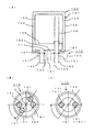
そして、この断熱材4で被覆されていない入口ポート7の開口筒部73および出口ポート8の開口筒部84に、温度上昇手段としてのヒータ9が設けられている。
【0016】
ヒータ9は電気を通電することで発熱するもので、図1(B),(C)に示すように、省電力を目的にヒータ膜体によって構成されている。ヒータ膜体は印刷及び蒸着法で作成した薄膜抵抗であり、高電気抵抗を確保する。膜材は白金等の体積固有抵抗が大きい材料が望ましい。
ヒータ9の基材側は開口筒部73,84が樹脂であるために直接ヒータ9の抵抗膜9aを載せ、膜表面には、熱伝導率が小さくかつ電気的に高い絶縁性を有する樹脂で被覆した積層構造である。
また、開口筒部73,84のヒータ9を布設する部位の両端部には、開口筒部73,84断面を絞る絞りを構成する凹部10が設けられ、ヒータ加熱を局所的に加熱する構成としている。凹部10は開口筒部73,84外周に全周的に設けられる環状溝であり、蓄熱時にタンク内の水温が低下しないようにする。
【0017】
このように、開口筒部73,84からの熱の流出に対してヒータ9の加熱によって抵抗層を設け、かつヒータ9を敷設する両端部に絞り(凹部10)を設け、ヒータ加熱を局所的な加熱とし、開口筒部73,84内側に存在する温水を効率よく加熱する。
本発明の蓄熱タンクによれば、エンジン運転時に温められた冷却水がタンク内に蓄えられる。蓄えられた冷却水は断熱材4によって外気と断熱され、温水が維持される。
入口,出口ポート7,8の開口筒部73,84が下向きに位置するように設置されるので、タンク内の冷却水の温度分布は、タンク内上部が高く下部が低い温度分布となる。本発明では、冷却水の入口,出口ポート7,8の開口筒部73,84がヒータ9によって常に高い温度に保たれるので、熱の流出に対する熱障壁となって高い温度を維持させる。
【0018】
ヒータ9が無い場合には、図2(A)に比較例として示すように、内タンク2および外タンク5が入口,出口ポート7,8に直接,間接的に接しているため、矢印に示すように、熱流が内タンク2のタンク壁から入口,出口ポート7,8の開口筒部73,84および外タンク5のタンク壁に伝わって放熱され、断熱材4の効果が発揮できない。タンク材として熱伝導率が小さい樹脂を使用したとしても、熱伝導率は断熱材4と比べて3けた又は4けた程度大きく、熱流は矢印の方向に向かって流出してしまう。したがって、タンク内温水は経過時間と共に大きな低下を示す。
【0019】
図2(B)は、ヒータを設けない蓄熱タンクと本発明のヒータを設けた蓄熱タンクの保温性能を比較した実験結果を示している。
実験は、ヒータを設けない蓄熱タンクと、本発明の蓄熱タンク内に所定温度の温水を供給し、36時間後の初期温度に対する温度差を示している。
その結果、ヒータ無しの場合には34〜35℃程度温度が低下したのに対して、ヒータを敷設した本発明の蓄熱タンクでは、温度差が11〜12℃程度と保温性が大きく向上した。
尚、図示していながヒータを敷設した位置より前のポートが大気に露出している場合、断熱材で被覆しておくことが望ましい。
【0020】
<第2の実施の形態>
図3には本発明の第2の実施の形態に係る蓄熱タンクを示している。
この実施の形態では、蓄熱タンク内の温水を高温のまま維持するため、冷却水の供給または回収を行わない場合には、蓄熱タンクと配管系の管を切り離すことにより蓄熱タンクからの熱の逃げを抑制するものである。
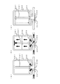
すなわち、この第2の実施の形態の蓄熱タンク100は、蓄熱タンク本体101と、蓄熱タンク本体101の開口部と配管系の管との連通・遮断を切り換える開口部連通遮断機構110とを備えた構造となっている。
【0021】
蓄熱タンク本体101は、内部中空の内タンク102と、内タンク102の外側を被覆する断熱層103と、熱媒体としての冷却水をタンク内に供給する入口ポート107と、タンク内の冷却水の排出する出口ポート108と、を備えている。
入口ポート107の開口部171と出口ポート108の開口部181は内タンク102の底壁102aに配置され、下向きに所定長さだけ突出している。
断熱層103は、内タンク102外周面を被覆して保温する断熱材104と、この断熱材104の外周を被覆する外タンク105とを備えた構成となっている。内タンク102の底壁102aを覆う断熱材104の厚みは開口部171,181の突出長さと同一で、開口部171,181の先端面は、内タンク102の底壁102aを被覆する断熱材104の下端面と同一面となっている。
なお、内タンク102内には、上部空間と底部空間を区分する混合防止板106が設けられている。混合防止板106は図1と同様に複数の孔を有し、出口ポート108から排出される高温の冷却水に入口ポート107から流入してくる低温の冷却水が急激に混合して温度が低下するのを防止するものである。
開口部連通遮断機構110は、冷却水の供給または排出を行う際には冷却水が流れる冷却水の熱媒体供給排出管としての供給管140および排出管150と前記入口ポート107および出口ポート108の開口部171,181とを連通し、冷却水の供給または排出を行なわない際には冷却水が流れる供給管140および排出管150と入口ポート107および出口ポート108の開口部171,181の連通を遮断するものである。
【0022】
図示例の開口部連通遮断機構110は、蓄熱タンク本体101を支える台座120を備えている。台座120は蓄熱タンク本体の入口ポート107および出口ポート108の開口部171,181が配置されるタンク底壁111と対向して配置され、蓄熱タンク本体101と回転軸Oを中心にして相対回転可能に組み付けられている。そして、回転駆動手段としてのモータ130により、蓄熱タンク本体101(または台座部)が回転駆動されるようになっている。たとえば、モータ130を台座120に固定し、モータ軸131を蓄熱タンク本体101に固定しておく。
【0023】
台座120には蓄熱タンク本体101の開口部171,181に対応して冷却水の供給、排出を行う供給管140および排出管150の管端部で構成される通路141,151が配置され、蓄熱タンク本体101と台座120の相対回転によって蓄熱タンク本体101側の開口部171,181と通路141,151が連通,遮断される構成となっている。
供給管140と排出管150の通路141,151と開口部171,181の連通を遮断する際には、開口部171,181は台座120に設けられた断熱材121で被覆される構成となっている。この断熱材121は台座120上面に設けられた凹部に組み込まれ、蓄熱タンク本体101の底面と回転摺動自在に接触している。この蓄熱タンク本体101底面も断熱材104が露出しており、断熱材104,121同士が互いに接触している。
また、断熱材104,121については、少なくとも熱伝導率が同程度の材料で構成される。ここで、本実施の形態では、断熱材として、SiO2またはAl2O3を用いている。これらの断熱材は、例えば直径1μm以下で厚さが10〜50nmの中空の球状に加工し、これを断熱層103に充填しても良い。また、断熱材としてポリウレタン、ポリスチレンを用いても良い。
【0024】
温水をエンジンに供給するときやエンジンから回収する時は、図3(C)に示すように、台座120の通路141,151と蓄熱タンク本体101の開口部171,181が連通するように、台座120と蓄熱タンク本体101とを相対的に回転移動させる。
温水を回収して保温するときは、図3(B)に示すように、台座120の通路141,151と蓄熱タンク本体101の開口部171,181が貫通しない十分な位置まで移動させる。このように、冷却水の通路となる開口部171,181を遮断し、かつ台座120の断熱材121で覆うことにより、外気との接触部分を減らし、熱の逃げ場をなくすことにより保温性が向上する。
これにより、蓄熱タンク本体101の温水の温度を長時間にわたって維持でき、温水をエンジン冷却系に供給することにより、暖気が終了した状態でエンジンを始動でき、エミッションの悪化を防止できる。
【0025】
図4は、開口部連通遮断機構の他の構成例を示している。
この開口部連通遮断機構210は所謂クイックカプラー方式で、蓄熱タンク本体の入口ポート107(出口ポート108)の開口部171(181)に対して供給管140(排出管150)の管端部を抜き差し可能とし、差し込んだ場合に開口部171(181)と供給管140(排出管150)が連通し、抜き出した場合に遮断する構成となっている。
この例では、開口部171(181)と管端部141a(151a)の双方に、スプリングの弾性復元力によって常時閉弁状態に保持される弁機構220,230が設けられ、差し込んだ場合にスプリングの力に抗して弁体が押されて開弁する構成となっている。
【0026】
開口部171(181)の弁機構220は、開口部171(181)内に上下移動自在に挿入された弁体221と、弁体221を開口部171から外に押し出す方向(図中下方)に付勢する第1,第2スプリング222,223と、付勢された弁体221が押しつけられて着座する開口部内周に設けられた環状弁座224とを備えている。弁体221は、環状弁座224に着座する円板部221aと、円板部221a中央から下方に突出する軸部221bと、を備えている。第1スプリング222は圧縮スプリングで弁体221の上方に配置され、第2スプリング223は引張スプリングで弁体221の下方に配置されている。
【0027】
管端部141a(151a)の弁機構230は、管端部141a(151a)内に上下移動自在に挿入された弁体231と、弁体231を管端部141a(151a)から押し出す方向に付勢するスプリング232と、スプリング232により付勢された弁体231が押しつけられて着座する管端部の開口端部内周に設けられた環状弁座233とを備えている。
この管端部141a(151a)を、不図示のモータやサーモスタットなどの駆動手段を使って上下させることにより、蓄熱タンク本体側の開口部171(181)に着脱させることができる。
【0028】
<その他の実施の形態>
次に、本発明と関連する発明の実施の形態を説明する。
関連発明1.
この発明は、蓄熱タンク内に混合防止板に関するものである。
蓄熱システムでは、電動ポンプ等で熱媒体としての冷却水を蓄熱タンク内に送り込むことにより、タンク内の温水を押し出して、必要なところに供給している。その際、冷えた水が上部空間に大量に入り込むと温水の温度が下がってしまうので、タンク内に底部空間と上部空間を区切る混合防止板を設け、冷えた水が上部空間の温水と急激に混合しないようにしている。
【0029】
しかし、混合防止板が固定式では、水と温水との非混合率は約70%で、30%程度は蓄熱された温水と冷えた水とが混合することにより全体の温度が下がる。
また、ポンプ作動直後は高温の温水が供給できるが、後半では冷えた水と混合し、低い温度の温水を供給することになって、供給する温水の温度にむらができてしまい、蓄熱していた熱量を有効に使用できない。
そこで、この発明では、流入する冷えた冷却水の量に応じて移動する可動式の混合防止板を設定することにより、温水と冷えたままの冷却水との混合を押え、高温を維持した状態で温水を供給させるようにしたものである。
【0030】
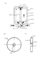
図5には、関連発明1の実施の形態に係る蓄熱タンクを示している。
すなわち、蓄熱タンク301は、内部中空のタンク本体302と、タンク本体302内に熱媒体としての冷却水を供給する入口ポート307と、タンク内の冷却水を排出する出口ポート308と、を備えている。タンク本体302は外側が断熱層で被覆されていてもよいし、被覆されていなくてもよい。
タンク本体302は、筒状の胴部321と、胴部321上端を閉塞する上壁部322と、胴部321下端を閉塞する下壁部323と、を備え、入口ポート307および出口ポート308は下壁部323に設けられている。出口ポート308は下壁部323から上壁部322近傍まで上下方向に延びる排出パイプ381を備えている。
【0031】
この排出パイプ381を支柱にして、上下に移動可能な混合防止板306が設けられている。すなわち、図5(B),(C)に示すように、混合防止板306は、中央に排出パイプ381に挿通されるパイプ挿入口361が設けられた円板状部材で、パイプ挿入口361の口縁に排出パイプ381外周に摺動自在に接触する円筒形状の内周ガイド362が、外径端部にタンク本体302の胴部321内周に摺動自在に接触する円筒形状の外周ガイド363が設けられている。
【0032】
本実施の形態の蓄熱タンクによれば、不図示のポンプが作動して冷たい水が入口ポート307からタンク本体302内に送り込まれると、送り込まれた水によって混合防止板306が押し上げられ、同時にタンク上部の温水が排出パイプ381の上端開口部からパイプ内部を通り出口ポート308から押し出され、冷却系の各部に供給される(図6(A),(B)参照)。この際、混合防止板306により上部にある温水と送り込まれてきた冷たい水の混合が妨げられる。
ポンプが停止し(あるいは弁等で)水の流れが止まると、混合防止板306は自重により下部に戻る(図6(C)参照)。
このように、簡単な構造でありながら、冷たい水が温水側に混入することがなく、高温のまま温水を排出できる。
【0033】
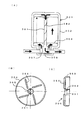
図7は、この関連発明1の他の実施の形態を示している。
この実施の形態では、温水の排出パイプ381に螺旋状の溝またはレールにより螺旋ガイド382が設けられている。そして、混合防止板306の上には羽364が設けられ、パイプ挿入口361の内周ガイド362に螺旋ガイド382に係合して螺旋ガイド382に沿ってトレースするように案内用の突起365が設けられている。
この実施の形態によれば、混合防止板306上昇時に突起365が螺旋ガイド382をトレースするように案内されるので、混合防止板306は回転しながら上昇し、羽364によって旋回流が生じ、排出パイプ381上端からパイプ内への温水がスムースに流れこむ。
【0034】
関連発明2.
この発明は、特に金属製の真空断熱タンクに関するものである。
金属製の真空断熱タンクでは、内タンクと外タンクの隙間を真空にした二重構造となっており、内タンクと外タンクが口部で連結されている。このような真空断熱タンクでは、熱が熱伝導率の高いタンク壁の金属部を伝わって、内タンクから外タンクに熱が逃げる。特に内タンクと外タンクが連結された口部周辺から逃げる熱量が多い。
そこで、本発明は、タンク本体の一部材質を変更することによって熱の逃げを抑えるものである。特に、内タンクの開口部と外タンクの開口部との結合部位からの放熱量を抑制することにより、保温能力向上を図るものである。
【0035】
図8には、関連発明2の実施の形態に係る蓄熱タンクを示している。
すなわち、蓄熱タンク400は、内部中空のタンク本体401と、タンク本体401の開口部402に組み付けられるハウジング420と、から構成されている。ハウジング420には、タンク本体401内に熱媒体としての冷却水を供給する入口ポート407と、タンク本体401内の冷却水を排出する出口ポート408と、を備えている。
【0036】
タンク本体401は金属製で、内タンク403と外タンク405の間に真空層404を設けた二重構造となっており、真空層404によって保温性を保っている。タンク本体401内には、下端が出口ポート408に接続される排出パイプ481が上下方向に延びている。また、タンク本体401には固定の混合防止板406が配設され、底部空間と上部空間を区分している。混合防止板406には複数の孔406aが設けられている。
タンク本体401の内タンク403と外タンク405は開口部402の先端で接合されており、内タンク403と外タンク405の接合部402a周辺に、タンク本体401を構成する金属より熱伝導率が低い断熱材409が挟まれており、タンク本体401のタンク壁を通じて伝わる熱伝導を抑えている。
【0037】
図8(B)は、接合例を拡大して示している。
図示例では、開口部402の内タンク403側のタンク壁が一部分断され、断熱材409が挟まれた構成となっている。断熱材409はタンク本体401のタンク材に用いられる金属よりも熱伝導率が低い材料であればよい。断熱材409と内タンク403の切断端との接合は、ねじを切ってねじ結合することが好ましい。
さらに、真空性を確保するために、断熱材409の表面にメッキ等の金属膜410が表面に貼り付けられている。金属膜410は金属なので熱伝導率は高いが、厚さを極限まで薄くすることで、熱の伝わりを下げることができる。
このように、開口部402の熱伝導率を下げることで、保温性を向上させることができる。
【0038】
図8(C)は、タンク本体401の開口部402の内タンク403と外タンク405の先端接合部を分断し、内タンク403と外タンク405の先端を断熱材409を介して接合したものである。
断熱材409を接合部に取り付けることで、熱の逃げの他に真空タンクで最も応力が加わる接合部の強度を向上させることも可能である。
断熱材409は内タンク403と外タンク405の双方とねじ結合しており、断熱材409の内周から外周および先端部の全体を金属膜410で被覆している。
【0039】
図8(D)は、タンク本体401の開口部402の外タンク405側のタンク壁が一部分断され、断熱材409が挟まれた構成となっている。
【0040】
関連発明3.
蓄熱タンクでは、タンク本体の外側が断熱材によって被覆されているが、断熱されていない入口,出口ポート周辺から熱が逃げやすい。
そこで、この発明は、このポート周辺からの放熱量を抑制することにより、保温能力向上を図るものである。
【0041】
図9(A)には、関連発明3の実施の形態に係る蓄熱タンクを示している。
すなわち、この蓄熱タンク501は樹脂製であり、内タンク502と外タンク505の間に超微細多孔質材等よりなる断熱材504が充填もしくは配置される。断熱材504の入った層は、必要に応じて(熱伝導率を下げたい場合)真空とされる。
内タンク502の底壁521には熱媒体としての冷却水の供給を行う入口ポート507と出口ポート508が設けられている。入口ポート507は、内タンク502の底壁521から下方に延び、断熱材504および外タンク505の底壁を貫通して所定長さだけ下方に突出している。出口ポート508は、内タンク502および外タンク505の下壁部に設けた孔に挿し通される上下方向に延びるパイプによって構成される。
【0042】
また、内タンク502内には、上部空間と底部空間を区分する混合防止板506が設けられている。混合防止板506には複数の孔506aが設けられると共に、出口ポート508が挿し通される孔が設けられている。混合防止板506の外周は内タンク502内周に固定されている。
そして、入口ポート507および出口ポート508の混合防止板506よりタンク外の先端まで、いずれのポートも下向きなので、混合防止板506より下部分581が、それぞれ断熱材510,511によって断熱されている。
また、混合防止板506も熱伝達率が低い材料として断熱材512にて構成される。
【0043】
入口ポート507および出口ポート508の混合防止板506より下の部分を断熱材510,511で断熱することで、ポート付近からの放熱を防止できる。特に、混合防止板506を断熱材とすることにより、混合防止板506の上下で温度差ができ、冷水が混入したときにタンク本体部分の水温低下が少なくなる。また、図9(B)に示すように、混合防止板506は断熱材とせず、入口ポート507および出口ポート508のみを断熱材510,511で断熱するだけでも、ポート付近からの放熱を防止できるので、簡易的に保温性を向上させることができる。
【0044】
【発明の効果】
以上説明したように、本発明によれば、外側が断熱層で覆われた蓄熱タンクであって、前記断熱層が被覆されていないタンク壁面の部位の少なくとも一部の温度を上昇させる温度上昇手段を設けたことにより、断熱層の被覆では断熱しきれないタンク壁を伝わって外部へ逃げる熱量を可及的に低減することができ、断熱層の断熱性能を十分に発揮させることができる。
【0045】
また、熱媒体が流れる熱媒体供給排出管と開口部を連通・遮断させる開口部連通遮断手段を設けたことにより、冷却水の供給または回収を行わない場合には、蓄熱タンクと配管系の管を切り離すことにより蓄熱タンクからの熱の逃げを可及的に抑制することができる。
【図面の簡単な説明】
【図1】 図1は本発明の第1の実施の形態に係る蓄熱タンクを示すもので、同図(A)は概略断面図、同図(B)はヒータ部分の部分拡大図、同図(C)はヒータ部分の模式的断面図である。
【図2】 図2(A)はヒータが無い比較例として示した蓄熱タンクの断面図、同図(B)はヒータが有る場合と無い場合の初期からの温度差を示すグラフである。
【図3】 図3は本発明の第2の実施の形態に係る蓄熱タンクを示すもので、同図(A)は概略断面図、同図(B),(C)は同図(A)の連通遮断機構の動作説明図である。
【図4】 図4(A),(B)は連通遮断機構の他の構成例の動作説明図である。
【図5】 図5(A)は本発明の関連発明1の蓄熱タンクの概略断面図、同図(B)は同図(A)の混合防止板の平面図、同図(C)は同図(B)の側面図である。
【図6】 図6(A)乃至(C)は図5(A)の蓄熱タンクの混合防止板の動作状態を示す概略断面説明図である。
【図7】 図7(A)は本発明の関連発明1の他の実施の形態に係る蓄熱タンクの概略断面図、同図(B)は同図(A)の混合防止板の平面図、同図(C)は同図(B)の側面図である。
【図8】 図8(A)は本発明の関連発明2の蓄熱タンクの概略断面図、同図(B)乃至(D)は内タンクと外タンクの連結部の各種構成例を示す部分断面図である。
【図9】 図9(A)は本発明の関連発明3の実施の形態に係る蓄熱タンクの概略断面図、同図(B)は関連発明3の他の実施の形態の概略断面図である。
【符号の説明】
1 蓄熱タンク
2 内タンク
3 隙間
4 断熱材
5 外タンク
6 混合防止板
7 入口ポート
8 出口ポート
9 ヒータ
10 凹部
21 胴部
22 上壁部
23 下壁部
51 胴部
52 上壁部
53 下壁部
71 筒口部
72 付け根部
73 開口筒部
81 排出パイプ
82 タンク内挿入部
83 断熱材被覆部
84 開口筒部
100 蓄熱タンク
101 蓄熱タンク本体
102 内タンク
102a 底壁
103 断熱層
104 断熱材
105 外タンク
106 混合防止板
107 入口ポート
108 出口ポート
110 開口部連通遮断機構
111 タンク底壁
120 台座
121 断熱材
130 モータ
131 モータ軸
140 供給管
141 通路
141a 管端部
150 排出管
171 開口部
181 開口部
210 開口部連通遮断機構
220 弁機構
221a 円板部
221b 軸部
221 弁体
222 スプリング
223 スプリング
224 環状弁座
230 弁機構
231 弁体
232 スプリング
233 環状弁座[0001]
BACKGROUND OF THE INVENTION
The present invention relates to a heat storage tank used for a cooling system of an internal combustion engine, for example.
[0002]
[Prior art]
As a heat insulating container that can be used as a conventional heat storage tank, for example, a heat insulating container as described in
This heat insulating container has a double structure in which the opening of the inner container and the opening of the outer container are connected, and a vacuum layer is formed between the inner container and the outer container. And by sticking a low thermal conductivity material having a lower thermal conductivity than the metal constituting the inner container to the inner wall around the opening of the inner container, the outer wall is connected to the outer container through the opening connected from the inner wall of the inner container. The amount of heat that is transmitted, that is, the amount of heat that is radiated is being reduced as much as possible.
[Patent Document 1]
Japanese Utility Model Publication No. 3-7597
[Patent Document 2]
JP-A-2-265513
[Patent Document 3]
JP-A-4-114614
[Patent Document 4]
Published technical bulletin 2001-6238
[Patent Document 5]
Japanese Utility Model Publication No. 63-68943
[Patent Document 6]
JP 2000-73764 A
[0003]
[Problems to be solved by the invention]
However, in the case of the above prior art, since the inner container and the outer container are connected, the amount of heat dissipated cannot be ignored, and if the heat medium is stored in a metal vacuum insulation container and left for a long time, the heat medium There is a risk that the heat medium at the desired temperature cannot be supplied.
[0004]
When used in an engine cooling system, the heat storage tank is connected to the engine through a cooling system pipe. When hot water is kept in the heat storage tank, the heat storage tank and the pipe pipe are connected, and heat is transferred from the heat storage tank to the pipe side through the connection between the tank wall and the pipe of the heat storage tank. The temperature in the heat storage tank will decrease.
[0005]
The present invention has been made to solve the above-described problems of the prior art, and the object of the present invention is to minimize the amount of heat that escapes to the outside through a tank wall that cannot be insulated by the insulation layer coating. The object is to provide a heat storage tank that can be reduced.
[0006]
[Means for Solving the Problems]
In order to achieve the above object, according to a first aspect of the present invention, the outflow of heat is shielded by increasing the temperature of the portion of the tank body that is not covered with the heat insulating layer.
That is, the heat storage tank is covered with a heat insulating layer on the outside, and is provided with a temperature raising means for raising the temperature of at least a part of a portion of the tank wall surface that is not covered with the heat insulating layer.
The portion of the tank wall surface not covered with the heat insulating layer is preferably an opening for supplying or discharging the heat medium.
[0007]
The temperature raising means is a heater that generates heat by energizing electricity, and the heater is preferably constituted by a heater film body in order to save power.
Moreover, if a restriction | limiting is provided in the both ends of the site | part which installs a heater, and a heater heating is performed locally, it can heat efficiently.
[0008]
In the second aspect of the invention, the hot water in the heat storage tank is maintained at a high temperature. Therefore, when the cooling water is not supplied or recovered, the heat from the heat storage tank is removed by separating the heat storage tank from the pipe. It is to suppress.
That is, a heat storage tank in which an outer side of an inner tank having an opening for supplying or discharging a heat medium is covered with a heat insulating layer, and the heat medium supply through which the heat medium flows when the heat medium is supplied or discharged The discharge pipe and the opening communicate with each other, and the heating medium supply / discharge pipe through which the heat medium flows when the heating medium is not supplied or discharged has an opening communication blocking means for blocking communication between the opening and the opening. .
[0009]
Here, the heat medium supply / discharge pipe is a pipe of the piping system, and the word “supply / discharge” is used to include both the case of supplying and the case of discharging. Includes supply-only tubes and discharge-only tubes. Also included are tubes that supply and discharge.
When the communication between the heat medium supply / discharge pipe and the opening is blocked, the opening can be insulated by covering the opening with a heat insulating material.
Moreover, if the heat insulating layer and the heat insulating material are made of the same material, the heat insulating performance of the heat insulating layer can be sufficiently exhibited. Furthermore, the manufacturing cost can be reduced.
[00010]
The opening communication blocking means includes a pedestal that is opposed to a tank wall surface on which an opening for supplying or discharging the heat medium of the heat storage tank body is disposed and is mounted to be rotatable relative to the heat storage tank body. The pedestal is provided with a passage connected to the heat medium supply / discharge pipe, and the opening on the heat storage tank main body side and the passage on the pedestal side are communicated and blocked by relative rotation of the heat storage tank main body and the pedestal. Is preferred.
[0011]
Further, the opening communication blocking means enables the pipe end of the heat medium supply / discharge pipe to be inserted into and removed from the opening that supplies or discharges the heat medium of the heat storage tank body. It is good also as a structure which interrupts | blocks when it communicates and it extracts.
[0012]
DETAILED DESCRIPTION OF THE INVENTION
The present invention will be described below based on the illustrated embodiments.
<First Embodiment>
FIG. 1 shows a cross-sectional structure of a heat storage tank according to the first embodiment of the present invention. This heat storage tank is a schematic diagram assuming a case where it is used as a heat storage tank for cooling water of an internal combustion engine. The heat storage tank cools the engine during engine operation, collects the high-temperature cooling water, and supplies it to the cooling system when the engine is restarted. It is to prevent.
[0013]
The
In this example, a heat insulating layer that covers the inner tank is constituted by the
The
[0014]
Further, in the
The
[0015]
The tip of the tube port 71 of the
About the
And the
[0016]
The
Since the
Moreover, the recessed
[0017]
In this way, a resistance layer is provided by heating of the
According to the heat storage tank of the present invention, the cooling water warmed during engine operation is stored in the tank. The stored cooling water is insulated from the outside air by the
Since the opening
[0018]
When the
[0019]
FIG. 2B shows the experimental results comparing the heat retention performance of the heat storage tank without the heater and the heat storage tank with the heater of the present invention.
The experiment shows a temperature difference with respect to the initial temperature after 36 hours when hot water having a predetermined temperature is supplied into the heat storage tank without the heater and the heat storage tank of the present invention.
As a result, the temperature decreased by about 34 to 35 ° C. in the case of no heater, whereas in the heat storage tank of the present invention in which the heater was laid, the temperature difference was about 11 to 12 ° C. and the heat retention was greatly improved.
In addition, although not shown, when the port before the position where the heater is laid is exposed to the atmosphere, it is desirable to cover it with a heat insulating material.
[0020]
<Second Embodiment>
FIG. 3 shows a heat storage tank according to the second embodiment of the present invention.
In this embodiment, since the hot water in the heat storage tank is maintained at a high temperature, when the cooling water is not supplied or recovered, the heat escape from the heat storage tank is performed by separating the heat storage tank from the piping system pipe. It suppresses.
That is, the heat storage tank 100 of the second embodiment includes a heat storage tank
[0021]
The heat storage tank
The opening 171 of the inlet port 107 and the opening 181 of the outlet port 108 are disposed on the bottom wall 102a of the inner tank 102 and protrude downward by a predetermined length.
The heat insulating layer 103 includes a heat insulating material 104 that covers the outer peripheral surface of the inner tank 102 and keeps it warm, and an outer tank 105 that covers the outer periphery of the heat insulating material 104. The thickness of the heat insulating material 104 covering the bottom wall 102 a of the inner tank 102 is the same as the protruding length of the openings 171, 181, and the front end surfaces of the openings 171, 181 are the heat insulating material 104 covering the bottom wall 102 a of the inner tank 102. It is the same surface as the lower end surface.
In the inner tank 102, a mixing prevention plate 106 for separating the upper space and the bottom space is provided. The mixing prevention plate 106 has a plurality of holes as in FIG. 1, and the low temperature cooling water flowing from the inlet port 107 is abruptly mixed with the high temperature cooling water discharged from the outlet port 108 to lower the temperature. This is to prevent this from happening.
When the cooling water is supplied or discharged, the opening communication blocking mechanism 110 includes a
[0022]
The opening communication blocking mechanism 110 in the illustrated example includes a pedestal 120 that supports the heat storage tank
[0023]
Corresponding to the openings 171 and 181 of the heat storage tank
When the communication between the
The heat insulating materials 104 and 121 are made of a material having at least the same thermal conductivity. Here, in this embodiment, as the heat insulating material, SiO 2 Or Al 2 O Three Is used. These heat insulating materials may be processed into a hollow spherical shape having a diameter of 1 μm or less and a thickness of 10 to 50 nm, for example, and filled into the heat insulating layer 103. Further, polyurethane or polystyrene may be used as the heat insulating material.
[0024]
When supplying hot water to the engine or collecting it from the engine, as shown in FIG. 3 (C), the pedestal is arranged so that the
When warm water is collected and kept warm, as shown in FIG. 3B, the
Thereby, the temperature of the hot water in the heat storage tank
[0025]
FIG. 4 shows another configuration example of the opening communication blocking mechanism.
The opening
In this example, both the opening 171 (181) and the pipe end 141a (151a) are provided with
[0026]
The
[0027]
The
The pipe end 141a (151a) can be attached to and detached from the opening 171 (181) on the heat storage tank main body side by moving up and down using a driving means such as a motor or a thermostat (not shown).
[0028]
<Other embodiments>
Next, an embodiment of the invention related to the present invention will be described.
The present invention relates to a mixing prevention plate in a heat storage tank.
In a heat storage system, cooling water as a heat medium is sent into a heat storage tank by an electric pump or the like to push out hot water in the tank and supply it to a necessary place. At that time, if a large amount of cold water enters the upper space, the temperature of the hot water will drop, so a mixing prevention plate that separates the bottom space from the upper space is provided in the tank, and the cold water rapidly Try not to mix.
[0029]
However, when the mixing prevention plate is a fixed type, the non-mixing ratio of water and warm water is about 70%, and about 30% mixes the warm water stored and the cold water to lower the overall temperature.
In addition, hot hot water can be supplied immediately after the pump is operated, but in the latter half, it is mixed with cold water and supplied with low temperature hot water, resulting in uneven temperature of the supplied hot water and storing heat. The amount of heat generated cannot be used effectively.
Therefore, in the present invention, by setting a movable mixing prevention plate that moves according to the amount of the cooled cooling water that flows in, the mixing of the hot water and the cooling water that has been cooled is suppressed, and the high temperature is maintained. It is designed to supply hot water.
[0030]
In FIG. 5, the thermal storage tank which concerns on embodiment of the
That is, the heat storage tank 301 includes an internal hollow tank
The
[0031]
Using the discharge pipe 381 as a support column, a mixing
[0032]
According to the heat storage tank of the present embodiment, when a pump (not shown) is operated and cold water is fed into the
When the pump is stopped (or by a valve or the like), the mixing
Thus, although it is a simple structure, cold water does not mix in the warm water side, and warm water can be discharged at a high temperature.
[0033]
FIG. 7 shows another embodiment of the
In this embodiment, the hot water discharge pipe 381 is provided with a spiral guide 382 by means of a spiral groove or rail. A blade 364 is provided on the mixing
According to this embodiment, since the projection 365 is guided so as to trace the spiral guide 382 when the mixing
[0034]
The present invention particularly relates to a metal vacuum insulation tank.
The metal vacuum heat insulation tank has a double structure in which the gap between the inner tank and the outer tank is evacuated, and the inner tank and the outer tank are connected at the mouth. In such a vacuum heat insulation tank, heat is transmitted through the metal part of the tank wall having high thermal conductivity, and the heat escapes from the inner tank to the outer tank. In particular, a large amount of heat escapes from the periphery of the mouth where the inner tank and the outer tank are connected.
Therefore, the present invention suppresses heat escape by changing a part of the material of the tank body. In particular, the heat retention capability is improved by suppressing the amount of heat released from the joint between the opening of the inner tank and the opening of the outer tank.
[0035]
In FIG. 8, the thermal storage tank which concerns on embodiment of the
That is, the heat storage tank 400 includes a hollow inner tank body 401 and a housing 420 assembled to the
[0036]
The tank body 401 is made of metal and has a double structure in which a vacuum layer 404 is provided between the
The
[0037]
FIG. 8B shows an enlarged joining example.
In the illustrated example, the tank wall on the
Further, a
In this way, the heat retention can be improved by reducing the thermal conductivity of the
[0038]
FIG. 8C shows a case where the front end joints of the
By attaching the
The
[0039]
FIG. 8D shows a configuration in which the tank wall on the outer tank 405 side of the
[0040]
In the heat storage tank, the outside of the tank body is covered with a heat insulating material, but heat easily escapes from the vicinity of the inlet and outlet ports that are not insulated.
Therefore, the present invention aims to improve the heat retention capability by suppressing the heat radiation from the periphery of the port.
[0041]
FIG. 9A shows a heat storage tank according to an embodiment of
That is, the heat storage tank 501 is made of resin, and a heat insulating material 504 made of an ultrafine porous material or the like is filled or disposed between the
The bottom wall 521 of the
[0042]
Further, in the
And since all the ports are downward from the mixing prevention plate 506 of the inlet port 507 and the outlet port 508 to the tip outside the tank, the lower portion 581 from the mixing prevention plate 506 is insulated by the heat insulating materials 510 and 511, respectively.
Further, the mixing prevention plate 506 is also composed of a
[0043]
Heat insulation from the vicinity of the ports can be prevented by insulating the portions of the inlet port 507 and the outlet port 508 below the mixing prevention plate 506 with the heat insulating materials 510 and 511. In particular, by using the mixing prevention plate 506 as a heat insulating material, a temperature difference can be made between the upper and lower sides of the mixing prevention plate 506, and a decrease in the water temperature in the tank body portion is reduced when cold water is mixed. Further, as shown in FIG. 9B, the mixing prevention plate 506 is not a heat insulating material, and heat radiation from the vicinity of the port can be prevented by only insulating the inlet port 507 and the outlet port 508 with the heat insulating materials 510 and 511. Therefore, heat retention can be improved easily.
[0044]
【The invention's effect】
As described above, according to the present invention, the temperature increasing means for increasing the temperature of at least a part of the portion of the tank wall surface that is covered with the heat insulating layer on the outside and is not covered with the heat insulating layer. By providing the heat insulation layer, it is possible to reduce as much as possible the amount of heat that escapes to the outside through the tank wall that cannot be insulated by the coating of the heat insulation layer, and the heat insulation performance of the heat insulation layer can be exhibited sufficiently.
[0045]
In addition, by providing an opening communication blocking means for connecting and blocking the opening and the heat medium supply / discharge pipe through which the heat medium flows, when the cooling water is not supplied or recovered, the heat storage tank and the piping system pipe It is possible to suppress heat escape from the heat storage tank as much as possible.
[Brief description of the drawings]
FIG. 1 shows a heat storage tank according to a first embodiment of the present invention, in which FIG. 1 (A) is a schematic sectional view, FIG. 1 (B) is a partially enlarged view of a heater portion, and FIG. (C) is a schematic cross-sectional view of a heater portion.
FIG. 2A is a cross-sectional view of a heat storage tank shown as a comparative example without a heater, and FIG. 2B is a graph showing a temperature difference from the initial when there is no heater and when there is no heater.
FIG. 3 shows a heat storage tank according to a second embodiment of the present invention. FIG. 3 (A) is a schematic sectional view, and FIGS. 3 (B) and (C) are the same figure (A). It is operation | movement explanatory drawing of this communication cutoff mechanism.
FIGS. 4A and 4B are operation explanatory views of another configuration example of the communication blocking mechanism.
5A is a schematic cross-sectional view of a heat storage tank according to
6 (A) to 6 (C) are schematic cross-sectional explanatory views showing the operating state of the mixing prevention plate of the heat storage tank of FIG. 5 (A).
FIG. 7 (A) is a schematic sectional view of a heat storage tank according to another embodiment of the
FIG. 8A is a schematic cross-sectional view of a heat storage tank according to
9A is a schematic cross-sectional view of a heat storage tank according to an embodiment of the
[Explanation of symbols]
1 Thermal storage tank
2 Inside tank
3 Clearance
4 Insulation
5 Outer tank
6 Mixing prevention plate
7 Entrance port
8 Exit port
9 Heater
10 recess
21 Torso
22 Upper wall
23 Lower wall
51 trunk
52 Upper wall
53 Lower wall
71 Tube port
72 Root
73 Opening cylinder
81 Discharge pipe
82 Tank insert
83 Insulation cover
84 Opening cylinder
100 heat storage tank
101 Heat storage tank body
102 inner tank
102a bottom wall
103 Thermal insulation layer
104 Thermal insulation
105 Outer tank
106 Mixing prevention plate
107 Inlet port
108 Exit port
110 Opening communication blocking mechanism
111 Tank bottom wall
120 pedestal
121 Insulation
130 motor
131 Motor shaft
140 Supply pipe
141 passage
141a Pipe end
150 discharge pipe
171 opening
181 opening
210 Opening communication blocking mechanism
220 Valve mechanism
221a Disc part
221b Shaft
221 Disc
222 Spring
223 Spring
224 Annular valve seat
230 Valve mechanism
231 Disc
232 Spring
233 Annular valve seat
Claims (5)
前記断熱層が被覆されていないタンク壁面の部位の少なくとも一部の温度を上昇させる温度上昇手段を設け、
前記温度上昇手段は電気を通電することで発熱するヒータであり、
前記ヒータはヒータ膜体によって構成されており、
前記ヒータを布設する部位の両端部に絞りを設けてヒータ加熱を局所的に行う構成としたことを特徴とする蓄熱タンク。A heat storage tank whose outside is covered with a heat insulating layer,
Providing a temperature raising means for raising the temperature of at least a part of the portion of the tank wall surface not covered with the heat insulating layer ;
The temperature raising means is a heater that generates heat by energizing electricity,
The heater is constituted by a heater film body,
A heat storage tank characterized in that the heater is locally heated by providing a restriction at both ends of a portion where the heater is installed .
前記熱媒体の供給または排出を行う際には熱媒体が流れる熱媒体供給排出管と開口部を連通し、熱媒体の供給または排出を行なわない際には熱媒体が流れる熱媒体供給排出管と開口部の連通を遮断する開口部連通遮断手段を有し、
前記熱媒体供給排出管と前記開口部の連通を遮断する際には開口部を断熱材で被覆する構成となっており、
前記断熱層と前記断熱材とは同一材料で構成することを特徴とする蓄熱タンク。A heat storage tank having an opening for supplying or discharging a heat medium and having an outer side covered with a heat insulating layer,
When the heat medium is supplied or discharged, the heat medium supply / discharge pipe through which the heat medium flows communicates with the opening, and when the heat medium is not supplied or discharged, the heat medium supply / discharge pipe through which the heat medium flows have a opening portion communication connection cutoff means for cutting off the communication of the opening,
When the communication between the heat medium supply / discharge pipe and the opening is cut off, the opening is covered with a heat insulating material,
The heat storage tank , wherein the heat insulating layer and the heat insulating material are made of the same material .
台座には熱媒体供給排出管につながる通路が設けられ、前記蓄熱タンク本体と台座の相対回転によって蓄熱タンク本体側の開口部と台座側の通路が連通,遮断される構成となっていることを特徴とする請求項3に記載の蓄熱タンク。The opening communication blocking means includes a pedestal that is opposed to a tank wall surface on which an opening for supplying or discharging the heat medium of the heat storage tank body is disposed and is mounted to be rotatable relative to the heat storage tank body. ,
The pedestal is provided with a passage connected to the heat medium supply / discharge pipe, and the heat storage tank main body side opening and the pedestal side passage are communicated and blocked by relative rotation of the heat storage tank main body and the pedestal. The heat storage tank according to claim 3 , wherein the heat storage tank is a heat storage tank.
ク。The opening communication blocking means enables the pipe end of the heat medium supply / discharge pipe to be inserted / removed with respect to the opening for supplying / discharging the heat medium of the heat storage tank body, and when inserted, the opening and the heat medium supply / discharge pipe The heat storage tank according to claim 3 , wherein the heat storage tank is configured to shut off when it is communicated and extracted.
Priority Applications (1)
| Application Number | Priority Date | Filing Date | Title |
|---|---|---|---|
| JP2003112701A JP4239658B2 (en) | 2003-04-17 | 2003-04-17 | Heat storage tank |
Applications Claiming Priority (1)
| Application Number | Priority Date | Filing Date | Title |
|---|---|---|---|
| JP2003112701A JP4239658B2 (en) | 2003-04-17 | 2003-04-17 | Heat storage tank |
Publications (2)
| Publication Number | Publication Date |
|---|---|
| JP2004317044A JP2004317044A (en) | 2004-11-11 |
| JP4239658B2 true JP4239658B2 (en) | 2009-03-18 |
Family
ID=33472831
Family Applications (1)
| Application Number | Title | Priority Date | Filing Date |
|---|---|---|---|
| JP2003112701A Expired - Fee Related JP4239658B2 (en) | 2003-04-17 | 2003-04-17 | Heat storage tank |
Country Status (1)
| Country | Link |
|---|---|
| JP (1) | JP4239658B2 (en) |
Families Citing this family (9)
| Publication number | Priority date | Publication date | Assignee | Title |
|---|---|---|---|---|
| KR100783055B1 (en) * | 2004-12-30 | 2007-12-07 | 이기운 | discharging system for heated water and container for heated water |
| JP4572757B2 (en) * | 2005-07-05 | 2010-11-04 | パナソニック株式会社 | Vacuum heat insulation container and heat storage type warming device for automobile using vacuum heat insulation container |
| JP4899943B2 (en) * | 2007-03-06 | 2012-03-21 | パナソニック株式会社 | Thermal insulation tank |
| JP5118500B2 (en) * | 2008-02-04 | 2013-01-16 | 本田技研工業株式会社 | Heat storage container |
| JP5178422B2 (en) * | 2008-09-16 | 2013-04-10 | カルソニックカンセイ株式会社 | Thermal storage device and manufacturing method thereof |
| JP6021931B2 (en) * | 2011-11-17 | 2016-11-09 | マーレ ベア ゲゼルシャフト ミット ベシュレンクテル ハフツング ウント コンパニー コマンディートゲゼルシャフトMAHLE Behr GmbH & Co.KG | Heat accumulator |
| JP2020023965A (en) * | 2018-07-25 | 2020-02-13 | 株式会社デンソー | Cooling system of vehicle |
| WO2020022104A1 (en) * | 2018-07-25 | 2020-01-30 | 株式会社デンソー | Vehicle cooling system |
| KR102280276B1 (en) * | 2020-03-20 | 2021-07-22 | 주식회사 월드원하이테크 | Heat pump system and cooling and heating system using the same |
-
2003
- 2003-04-17 JP JP2003112701A patent/JP4239658B2/en not_active Expired - Fee Related
Also Published As
| Publication number | Publication date |
|---|---|
| JP2004317044A (en) | 2004-11-11 |
Similar Documents
| Publication | Publication Date | Title |
|---|---|---|
| JP4239658B2 (en) | Heat storage tank | |
| JP2005525505A (en) | Switchable exhaust heat exchanger | |
| JPH09189291A (en) | Hot water circulating pump | |
| JP2009186056A (en) | Heat storage container | |
| WO2010054559A1 (en) | Automatic cold water recycling thermostatic faucet | |
| WO2002008585A1 (en) | Seal member, and construction for attaching thermostats using this seal member | |
| JPS59101572A (en) | Low-temperature starter for car | |
| JPS63305060A (en) | Hot water feeding tank | |
| JP2827208B2 (en) | Hot water heating system for vehicles | |
| CN113614343B (en) | Constant temperature device | |
| JPH1071840A (en) | Heat insulation tank | |
| CN208296127U (en) | The radiator and air conditioner of air conditioner frequency-variable module | |
| JPH0485091U (en) | ||
| CN213066531U (en) | Fast-assembling type water heating footstock | |
| JP2513071Y2 (en) | Heat storage device | |
| CN217874491U (en) | Valve heat-insulation gate valve | |
| CN215522075U (en) | Anti-freezing valve and water heater applying same | |
| JPH06108043A (en) | Heat storage apparatus | |
| KR101992175B1 (en) | Low-power consumption heating system for reducing heat transfer fluid inside core | |
| CN218033357U (en) | Heat insulation and conduction contact switch and heat storage heater | |
| JP5926057B2 (en) | Temperature control ring for vehicle air pump | |
| CN210859279U (en) | Cold and warm dual-purpose fan | |
| JPH0924728A (en) | Heat insulation tank | |
| JP3821337B2 (en) | Air cleaner air heater | |
| JP4206619B2 (en) | Heat storage device for internal combustion engine |
Legal Events
| Date | Code | Title | Description |
|---|---|---|---|
| A621 | Written request for application examination |
Free format text: JAPANESE INTERMEDIATE CODE: A621 Effective date: 20051219 |
|
| A977 | Report on retrieval |
Free format text: JAPANESE INTERMEDIATE CODE: A971007 Effective date: 20080725 |
|
| A131 | Notification of reasons for refusal |
Free format text: JAPANESE INTERMEDIATE CODE: A131 Effective date: 20080805 |
|
| A521 | Written amendment |
Free format text: JAPANESE INTERMEDIATE CODE: A523 Effective date: 20081003 |
|
| TRDD | Decision of grant or rejection written | ||
| A01 | Written decision to grant a patent or to grant a registration (utility model) |
Free format text: JAPANESE INTERMEDIATE CODE: A01 Effective date: 20081202 |
|
| A01 | Written decision to grant a patent or to grant a registration (utility model) |
Free format text: JAPANESE INTERMEDIATE CODE: A01 |
|
| A61 | First payment of annual fees (during grant procedure) |
Free format text: JAPANESE INTERMEDIATE CODE: A61 Effective date: 20081215 |
|
| FPAY | Renewal fee payment (event date is renewal date of database) |
Free format text: PAYMENT UNTIL: 20120109 Year of fee payment: 3 |
|
| FPAY | Renewal fee payment (event date is renewal date of database) |
Free format text: PAYMENT UNTIL: 20120109 Year of fee payment: 3 |
|
| FPAY | Renewal fee payment (event date is renewal date of database) |
Free format text: PAYMENT UNTIL: 20130109 Year of fee payment: 4 |
|
| FPAY | Renewal fee payment (event date is renewal date of database) |
Free format text: PAYMENT UNTIL: 20130109 Year of fee payment: 4 |
|
| LAPS | Cancellation because of no payment of annual fees |