JP4238932B2 - How to manage foamable mixtures - Google Patents
How to manage foamable mixtures Download PDFInfo
- Publication number
- JP4238932B2 JP4238932B2 JP2007521265A JP2007521265A JP4238932B2 JP 4238932 B2 JP4238932 B2 JP 4238932B2 JP 2007521265 A JP2007521265 A JP 2007521265A JP 2007521265 A JP2007521265 A JP 2007521265A JP 4238932 B2 JP4238932 B2 JP 4238932B2
- Authority
- JP
- Japan
- Prior art keywords
- foamable mixture
- viscosity
- mixture
- measured
- moisture
- Prior art date
- Legal status (The legal status is an assumption and is not a legal conclusion. Google has not performed a legal analysis and makes no representation as to the accuracy of the status listed.)
- Active
Links
- 239000000203 mixture Substances 0.000 title claims description 130
- 238000000034 method Methods 0.000 claims description 34
- XLYOFNOQVPJJNP-UHFFFAOYSA-N water Substances O XLYOFNOQVPJJNP-UHFFFAOYSA-N 0.000 claims description 27
- 239000000523 sample Substances 0.000 claims description 16
- 238000003756 stirring Methods 0.000 claims description 16
- 239000003232 water-soluble binding agent Substances 0.000 claims description 15
- 238000002156 mixing Methods 0.000 claims description 12
- 238000005259 measurement Methods 0.000 claims description 6
- 238000000691 measurement method Methods 0.000 claims description 6
- 230000002950 deficient Effects 0.000 claims description 2
- 239000006260 foam Substances 0.000 claims description 2
- 230000007246 mechanism Effects 0.000 description 24
- VYPSYNLAJGMNEJ-UHFFFAOYSA-N Silicium dioxide Chemical compound O=[Si]=O VYPSYNLAJGMNEJ-UHFFFAOYSA-N 0.000 description 21
- 239000004576 sand Substances 0.000 description 17
- 238000000465 moulding Methods 0.000 description 11
- 238000002347 injection Methods 0.000 description 8
- 239000007924 injection Substances 0.000 description 8
- 229920002451 polyvinyl alcohol Polymers 0.000 description 8
- 239000004372 Polyvinyl alcohol Substances 0.000 description 7
- KRKNYBCHXYNGOX-UHFFFAOYSA-N citric acid Chemical compound OC(=O)CC(O)(C(O)=O)CC(O)=O KRKNYBCHXYNGOX-UHFFFAOYSA-N 0.000 description 6
- 238000003825 pressing Methods 0.000 description 6
- 239000011230 binding agent Substances 0.000 description 5
- 238000007726 management method Methods 0.000 description 5
- 238000005266 casting Methods 0.000 description 4
- 230000008602 contraction Effects 0.000 description 4
- 239000012530 fluid Substances 0.000 description 4
- 229910052956 cinnabar Inorganic materials 0.000 description 3
- 238000001125 extrusion Methods 0.000 description 3
- 238000005187 foaming Methods 0.000 description 3
- 229920001353 Dextrin Polymers 0.000 description 2
- 239000004375 Dextrin Substances 0.000 description 2
- 229920002472 Starch Polymers 0.000 description 2
- 235000019425 dextrin Nutrition 0.000 description 2
- 238000001704 evaporation Methods 0.000 description 2
- 238000010438 heat treatment Methods 0.000 description 2
- 230000000149 penetrating effect Effects 0.000 description 2
- 239000000377 silicon dioxide Substances 0.000 description 2
- 230000000087 stabilizing effect Effects 0.000 description 2
- 235000019698 starch Nutrition 0.000 description 2
- 239000008107 starch Substances 0.000 description 2
- LFQSCWFLJHTTHZ-UHFFFAOYSA-N Ethanol Chemical compound CCO LFQSCWFLJHTTHZ-UHFFFAOYSA-N 0.000 description 1
- IMROMDMJAWUWLK-UHFFFAOYSA-N Ethenol Chemical compound OC=C IMROMDMJAWUWLK-UHFFFAOYSA-N 0.000 description 1
- 229920000881 Modified starch Polymers 0.000 description 1
- 239000012615 aggregate Substances 0.000 description 1
- PNEYBMLMFCGWSK-UHFFFAOYSA-N aluminium oxide Inorganic materials [O-2].[O-2].[O-2].[Al+3].[Al+3] PNEYBMLMFCGWSK-UHFFFAOYSA-N 0.000 description 1
- 230000001174 ascending effect Effects 0.000 description 1
- 230000005540 biological transmission Effects 0.000 description 1
- 150000001720 carbohydrates Chemical class 0.000 description 1
- 238000001816 cooling Methods 0.000 description 1
- KZHJGOXRZJKJNY-UHFFFAOYSA-N dioxosilane;oxo(oxoalumanyloxy)alumane Chemical compound O=[Si]=O.O=[Si]=O.O=[Al]O[Al]=O.O=[Al]O[Al]=O.O=[Al]O[Al]=O KZHJGOXRZJKJNY-UHFFFAOYSA-N 0.000 description 1
- 230000000694 effects Effects 0.000 description 1
- 230000003028 elevating effect Effects 0.000 description 1
- 230000008020 evaporation Effects 0.000 description 1
- 238000002474 experimental method Methods 0.000 description 1
- 239000011810 insulating material Substances 0.000 description 1
- 239000000463 material Substances 0.000 description 1
- 229910052863 mullite Inorganic materials 0.000 description 1
- 229910052609 olivine Inorganic materials 0.000 description 1
- 239000010450 olivine Substances 0.000 description 1
- 239000002245 particle Substances 0.000 description 1
- 238000005070 sampling Methods 0.000 description 1
- 238000007127 saponification reaction Methods 0.000 description 1
- 229930182490 saponin Natural products 0.000 description 1
- 150000007949 saponins Chemical class 0.000 description 1
- 235000017709 saponins Nutrition 0.000 description 1
- 239000000126 substance Substances 0.000 description 1
- 229920002554 vinyl polymer Polymers 0.000 description 1
- 229940088594 vitamin Drugs 0.000 description 1
- 229930003231 vitamin Natural products 0.000 description 1
- 235000013343 vitamin Nutrition 0.000 description 1
- 239000011782 vitamin Substances 0.000 description 1
- 150000003722 vitamin derivatives Chemical class 0.000 description 1
- 230000004580 weight loss Effects 0.000 description 1
- 229910052845 zircon Inorganic materials 0.000 description 1
- GFQYVLUOOAAOGM-UHFFFAOYSA-N zirconium(iv) silicate Chemical compound [Zr+4].[O-][Si]([O-])([O-])[O-] GFQYVLUOOAAOGM-UHFFFAOYSA-N 0.000 description 1
Images


Classifications
-
- B—PERFORMING OPERATIONS; TRANSPORTING
- B22—CASTING; POWDER METALLURGY
- B22C—FOUNDRY MOULDING
- B22C5/00—Machines or devices specially designed for dressing or handling the mould material so far as specially adapted for that purpose
- B22C5/14—Equipment for storing or handling the dressed mould material, forming part of a plant for preparing such material
-
- B—PERFORMING OPERATIONS; TRANSPORTING
- B22—CASTING; POWDER METALLURGY
- B22C—FOUNDRY MOULDING
- B22C19/00—Components or accessories for moulding machines
- B22C19/04—Controlling devices specially designed for moulding machines
-
- B—PERFORMING OPERATIONS; TRANSPORTING
- B22—CASTING; POWDER METALLURGY
- B22C—FOUNDRY MOULDING
- B22C5/00—Machines or devices specially designed for dressing or handling the mould material so far as specially adapted for that purpose
-
- B—PERFORMING OPERATIONS; TRANSPORTING
- B22—CASTING; POWDER METALLURGY
- B22C—FOUNDRY MOULDING
- B22C5/00—Machines or devices specially designed for dressing or handling the mould material so far as specially adapted for that purpose
- B22C5/04—Machines or devices specially designed for dressing or handling the mould material so far as specially adapted for that purpose by grinding, blending, mixing, kneading, or stirring
-
- B—PERFORMING OPERATIONS; TRANSPORTING
- B22—CASTING; POWDER METALLURGY
- B22C—FOUNDRY MOULDING
- B22C9/00—Moulds or cores; Moulding processes
-
- B—PERFORMING OPERATIONS; TRANSPORTING
- B22—CASTING; POWDER METALLURGY
- B22C—FOUNDRY MOULDING
- B22C9/00—Moulds or cores; Moulding processes
- B22C9/02—Sand moulds or like moulds for shaped castings
Description
本発明は、発泡性混合物の管理方法に関する。さらに詳しくは、粒子状骨材、水溶性バインダおよび水を混合し、攪拌してなる発泡性混合物を、加熱された金型のキャビティに圧入方式により充填して鋳型、たとえば主型や中子などを造型するにあたり、前記発泡性混合物を所定の正常状態に製造するための発泡性混合物の管理方法に関する。 The present invention relates to a method for managing a foamable mixture. More specifically, a foaming mixture obtained by mixing and stirring particulate aggregate, a water-soluble binder and water is filled in a cavity of a heated mold by a press-fitting method, such as a mold such as a main mold or a core. The present invention relates to a method for managing a foamable mixture for producing the foamable mixture in a predetermined normal state.
近年、鋳造後の崩壊性が良いとして、粒子状骨材の粘結剤として水溶性バインダを用い、かつ加熱により水分を蒸発させて水溶性バインダを硬化させることにより鋳型を造型することが提案されている。 In recent years, it has been proposed to mold a mold by using a water-soluble binder as a binder for particulate aggregates and evaporating moisture by heating to cure the water-soluble binder because it has good disintegration after casting. ing.
この種の鋳型を造型するための鋳型造型装置として、たとえば上下方向へ延びる円筒と、この円筒内に上下動可能に配設されたプランジャと、円筒の下端開口を開閉するゲートとを、昇降可能に設けて、流動砂の金型への圧入手段を構成し、さらに、前記円筒の中段に開口を設けてこの開口に、流動砂を得るミキサーを接続したものがある(特開昭55−54241号公報参照)。 As a mold making apparatus for making this type of mold, for example, a vertically extending cylinder, a plunger disposed in the cylinder so as to be movable up and down, and a gate for opening and closing the lower end opening of the cylinder can be moved up and down. And a means for press-fitting the fluid sand into the mold, and an opening is provided in the middle of the cylinder, and a mixer for obtaining the fluid sand is connected to the opening (Japanese Patent Laid-Open No. 55-54241). Issue gazette).
また、前記従来の鋳型造型装置においては、円筒の中段にもゲートを設けたり、円筒や下側のゲートやプランジャのレベルを変えたりして、金型に圧入するため円筒に投入される流動砂の分量を変更することができるようにされている。 Further, in the conventional mold making apparatus, the fluid sand that is put into the cylinder for press-fitting into the mold by changing the level of the cylinder, the lower gate and the plunger by providing a gate in the middle of the cylinder. You have been able to change the amount.
しかしながら、前記従来の鋳型造型装置では、水溶性バインダを粘結剤とした鋳型材料である発泡性混合物は、水分が低すぎるときは、混合物の流動性が悪化し、充填が充分に確保できないため、水分を追加しさらに混練する必要がある。 However, in the conventional mold making apparatus, the foamable mixture, which is a mold material using a water-soluble binder as a binder, deteriorates the fluidity of the mixture when the moisture is too low, so that sufficient filling cannot be ensured. It is necessary to add water and knead further.
また、発泡性混合物の粘度が高過ぎる場合も、金型のキャビティへの発泡性混合物の充填が充分に確保できないため、再混練する必要がある。 In addition, even when the foamable mixture has a too high viscosity, it is necessary to re-knead because sufficient filling of the foamable mixture into the mold cavity cannot be ensured.
そこで、本発明は、叙上の事情に鑑み、金型に圧入する前の発泡性混合物の状態を監視し、かつ管理して、造型時の充填性を安定させることにより、鋳型強度を均一に製造することができる発泡性混合物の管理方法を提供することを目的とする。 Therefore, in view of the above circumstances, the present invention monitors and manages the state of the foamable mixture before being press-fitted into the mold, thereby stabilizing the filling property at the time of molding, thereby making the mold strength uniform. It aims at providing the management method of the foamable mixture which can be manufactured.
本発明の発泡性混合物の管理方法は、粒子状骨材、水溶性バインダおよび水を混合し、攪拌してなる発泡性混合物を、加熱された金型のキャビティに圧入方式により充填して鋳型を造型するにあたり、前記発泡性混合物の混合状態を管理する発泡性混合物の管理方法であって、(a)前記発泡性混合物の温度を測定する工程と、(b)予め求められている、該温度と相関関係がある、発泡性混合物を圧入方式により充填して鋳型を造型することが可能な、造型可能混合状態から、前記測定した温度に基づいて、前記発泡性混合物の水分および粘度の基準値を決定する工程と、(c)前記発泡性混合物の水分を測定する工程と、(d)当該測定した水分が前記水分の基準値の範囲内にあるか否かを判断する工程と、(e)前記測定した水分が前記水分の基準値の範囲内にある場合、前記発泡性混合物の粘度を測定する工程と、(f)当該測定した粘度が前記粘度の基準値の範囲内にあるか否かを判断する工程と、(g)前記測定した粘度が前記粘度の基準値の範囲内にある場合、前記発泡性混合物が正常状態にあると判定する工程とを含むことを特徴としている。 The method for managing the foamable mixture of the present invention comprises mixing a particulate aggregate, a water-soluble binder, and water, filling the stirred foamable mixture into a cavity of a heated mold by a press-fitting method, and filling a mold. A method for managing a foamable mixture for managing the mixing state of the foamable mixture in molding, wherein (a) a step of measuring the temperature of the foamable mixture, and (b) the temperature obtained in advance Based on the measured temperature from the moldable mixed state where the mold can be formed by filling the foamable mixture by press-fitting method, and the reference value of the moisture and viscosity of the foamable mixture determining a, a step of determining whether or not within the reference value of the process and, (d) moisture the measurement is the moisture measuring water content of (c) the foamable mixture ( e) The measured moisture is before If within the range of the reference value of the water, and measuring the viscosity of the foamable mixture, a step of determining whether (f) the measured viscosity is within the range of the reference value of the viscosity And (g) determining that the foamable mixture is in a normal state when the measured viscosity is within the range of the reference value of the viscosity.
本発明によれば、造型時の充填性を安定させることにより、鋳型強度を均一に製造することができる。 According to the present invention, the mold strength can be uniformly produced by stabilizing the filling property at the time of molding.
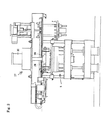
以下、添付図面に基づいて本発明の発泡性混合物の管理方法を説明する。まず、本発明に用いられる鋳型造型装置は、図1〜2に示されるように、定盤状の機台1に2個の上向きのシリンダ2、2が設置してあり、さらに前記機台1の四隅には4本のガイドロッド3、3がそれぞれ立設してある。前記2個のシリンダ2、2のピストンロッドの上端間には前記4本のガイドロッド3、3に摺動および昇降可能に装架した昇降フレーム4が下面にて架設してあり、昇降フレーム4の上面には水平割金型5の下金型6が取り付けてある。また、下金型6の真上には前記水平割金型5の上金型7が前記ガイドロッド3における前記下金型6の上方に装着された4組の支持機構8、8によって支持して配置されている。
Hereinafter, the management method of the foamable mixture of this invention is demonstrated based on an accompanying drawing. First, as shown in FIGS. 1 and 2, the mold making apparatus used in the present invention has two
また、前記4本のガイドロッド3、3の上端間には左右方向へ延びる天井フレーム9が架設してあり、天井フレーム9の下部における右側位置には、攪拌槽としての機能と、圧入筒としての機能を併せ持つ混合物収納手段10が、第1走行台車11を介して左側へ移動可能にして配置してあり、前記混合物収納手段10は、直方体を成すとともに上下に貫通する中空を有する中空直方体12と、この中空直方体12の下端に固着してこれの下端開口部を閉鎖しかつ混合物を射出する複数の射出孔13、13を透設した底板14とで構成してあり、この底板14は上部を水冷構造にしてあり、また下部を断熱材で構成されている。
Further, a
また、前記天井フレーム9の上面における右側位置には、前記混合物収納手段10内に投入される粒子状骨材、常温で可溶性である水溶性バインダおよび水を混合し、攪拌発泡させる攪拌羽根機構15が装着されている。なお、前記粒子状骨材としては、たとえば硅砂とすることができる。また、該粒子状骨材の粘結剤としての水溶性バインダとしては、ポリビニルアルコールとすることができる。前記攪拌羽根機構15においては、攪拌羽根16がモータ17の出力軸に伝動機構18を介して連結してあり、前記モータ17は前記天井フレーム9に装着された下向きのシリンダ19の縮伸作動によって昇降する支持部材20に装着してあり、さらに、支持部材20には前記混合物収納手段10の上端開口部を閉鎖するカバー21が装着してあって、前記攪拌羽根16および前記カバー21は、前記シリンダ19の縮伸作動によって昇降するようになっている。
Further, at the right side position on the upper surface of the
また、前記天井フレーム9における前記攪拌羽根機構15の真下位置には、前記混合物収納手段10の射出孔13、13を閉塞する栓手段22が配設してあり、栓手段22においては、前記射出孔13、13に入出可能な複数の栓23、23が支持板24を介して上向きのシリンダ25のピストンロッドの上端に装着してあって、栓23、23はシリンダ25の伸縮作動によって上下動するようになっており、前記シリンダ25は支持部材26、26を介して前記天井フレーム9に装着してある。なお、複数の前記栓23、23を前記射出孔13、13に挿入することにより射出孔13、13を清掃することもできる。
Further, a plug means 22 for closing the
また、前記天井フレーム9の上面における前記水平割金型5の真上位置には、前記混合物収納手段10内の混合物を押圧して前記混合物収納手段10の射出孔13、13から射出する押圧機構27が装着してあり、押圧機構27においては、上下に貫通する複数の排気孔28、28を有するピストン29が下向きのシリンダ30の縮伸作動によって上下動するようになっている。
Further, a pressing mechanism that presses the mixture in the mixture storage means 10 and injects it from the
また、前記天井フレーム9の下部における左側位置には、前記上金型7から鋳型を押し出す鋳型押出し機構31が、第2走行台車32を介して右側へ移動可能にして配置してあり、鋳型押出し機構31においては、複数の鋳型押出しピン33、33が押出し板34を介して下向きのシリンダ35のピストンロッドの下端に装着してあって、前記鋳型押出しピン33、33は前記シリンダ35の縮伸作動によって上下動するようになっている。
Further, a
本発明は、所定の品質をもった鋳型を製造するためには、発泡性混合物の管理が重要であることに鑑み、前記鋳型造型装置を用いて、前記発泡性混合物を加熱された金型のキャビティに圧入方式により充填して鋳型を造型するにあたり、該金型に圧入する前の前記発泡性混合物の状態を監視し、管理するようにしている。 In view of the importance of the management of the foamable mixture in order to produce a mold having a predetermined quality, the present invention uses the mold making apparatus to form a mold in which the foamable mixture is heated. When forming a mold by filling the cavity by press-fitting method, the state of the foamable mixture before press-fitting into the mold is monitored and managed.
すなわち、本発明は、まず発泡性混合物の温度を測定したのち、予め求められている、該温度と相関関係がある、発泡性混合物を圧入方式により充填して鋳型を造型することが可能な、造型可能混合状態(水分、粘度、砂の種類や粒度、バインダの種類や量に影響する)の関係から前記測定した温度に基づいて、前記発泡性混合物の混合状態を示す水分と粘度の基準値を決定する。 That is, in the present invention, first, after measuring the temperature of the foamable mixture, a mold is formed by filling the foamable mixture by a press-fitting method , which has a correlation with the temperature obtained in advance . Based on the temperature measured from the relationship of the moldable mixing state (influencing moisture, viscosity, sand type and particle size, binder type and amount), the reference value of moisture and viscosity indicating the mixing state of the foamable mixture To decide.
ついで前記発泡性混合物の混合状態を測定したのち、当該測定した状態値(水分と粘度の値)が前記基準値の範囲(たとえば、基準値の上限しきい値と下限しきい値のあいだ)内にあるか否かを判断する。 Then After measuring the mixed state of the foamable mixture, the measurement condition value range (the value of water and the viscosity) is the reference value (for example, between the upper and lower thresholds of the reference value) It is judged whether it is in.
ついで当該判断に基づいて、前記発泡性混合物が正常状態にあるか、または前記発泡性混合物を調整するかを判定する。かかる判断により、前記発泡性混合物が正常状態、すなわち測定した状態値が基準値の範囲内にあると判定される場合、該発泡性混合物を加熱された金型のキャビティに圧入方式により充填して鋳型を造型する。一方、前記発泡性混合物を調整、すなわち測定した状態値が基準値の範囲内にないと判定される場合、粘度および/または水分の成分調整を行ったのち、再度、発泡性混合物の状態の監視を続行する。 Then, based on the determination, it is determined whether the foamable mixture is in a normal state or the foamable mixture is adjusted. If it is determined by this determination that the foamable mixture is in a normal state, that is, the measured state value is within the range of the reference value, the foamable mixture is filled into a heated mold cavity by a press-fitting method. Make a mold. On the other hand, when the foamable mixture is adjusted, that is, when it is determined that the measured state value is not within the range of the reference value, the viscosity and / or moisture components are adjusted, and then the state of the foamable mixture is monitored again. To continue.
つぎに、本発明の一実施の形態にかかわる管理方法の手順を図3に基づいてさらに説明する。 Next, the procedure of the management method according to the embodiment of the present invention will be further described with reference to FIG.
(a)図3に示されるように、発泡性混合物の温度Tを温度計測手段により測定する(ステップS1)。 (A) As shown in FIG. 3, the temperature T of the foamable mixture is measured by the temperature measuring means (step S1).
該発泡性混合物は、混合物収納手段内に投入された粒子状骨材、水溶性バインダおよび水を攪拌羽根機構により混合し、攪拌発泡されている。なお、前記粒子状骨材としては、たとえば硅砂、アルミナ砂、オリビン砂、クロマイト砂、ジルコン砂、ムライト砂または各種の人工骨材などとすることができる。また、該粒子状骨材の粘結剤としての水溶性バインダとしては、ポリビニルアルコール、たとえばケン化度80モル%から95モル%までのポリビニルアルコールもしくはその誘導体、および/またはα化澱粉、デキストリンもしくはその誘導体、サポニン、糖類などとすることができる。該水溶性バインダは前記粒子状骨材に対し、たとえば0.3wt%〜10wt%重量部を含有させる。また、水はアルカリ性の水以外の水である。水は前記粒子状骨材および水溶性バインダに対し、たとえば2〜10%である。また、前記温度計測手段としては、とくに限定されるものではないが、接触型または非接触型の温度計測手段、たとえば接触型の温度検出器として、熱電対方式の温度センサなどを用いることができ、また非接触型の温度検出器として、レーザや、赤外線(サーモグラフ)、超音波などを用いた方式の温度センサを用いることができる。 The foamable mixture is stirred and foamed by mixing the particulate aggregate, water-soluble binder and water charged in the mixture storage means by a stirring blade mechanism. Examples of the particulate aggregate include dredged sand, alumina sand, olivine sand, chromite sand, zircon sand, mullite sand, and various artificial aggregates. Further, as the water-soluble binder as the binder for the particulate aggregate, polyvinyl alcohol, for example, polyvinyl alcohol having a saponification degree of 80 mol% to 95 mol% or a derivative thereof, and / or pregelatinized starch, dextrin or Derivatives thereof, saponins, saccharides and the like can be used. The water-soluble binder contains, for example, 0.3 wt% to 10 wt% by weight with respect to the particulate aggregate. The water is water other than alkaline water. Water is, for example, 2 to 10% with respect to the particulate aggregate and the water-soluble binder. The temperature measuring means is not particularly limited, but a contact type or non-contact type temperature measuring means, for example, a thermocouple type temperature sensor can be used as a contact type temperature detector. Further, as the non-contact type temperature detector, a temperature sensor using a laser, infrared (thermograph), ultrasonic wave, or the like can be used.
(b)ついで予め求められている発泡性混合物の造型可能混合状態の関係から前記測定した温度に基づいて、前記発泡性混合物の混合状態を示す、造型の品質に影響を及ぼす水分および粘度の基準値Ws、Vsを決定する(ステップS2)。 (B) Next, a standard of moisture and viscosity that affects the quality of molding, which indicates the mixing state of the foamable mixture based on the measured temperature based on the relationship between the preliminarily determined foamable mixture and the moldable mixing state. Values Ws and Vs are determined (step S2).
発泡性混合物の温度変化や、水分、粘度の度合いなどによって、混合物の流動性や、気泡率が変化し、たとえば造型時の充填性や、鋳型強度などの鋳型の造型品質が異なることから、予め温度、水分および粘度などの相関関係が前記発泡性混合物の造型可能混合状態の関係として実験にて求められている。 Depending on the temperature change of the foamable mixture, the degree of moisture, viscosity, etc., the fluidity and bubble ratio of the mixture will change.For example, the molding quality of the mold, such as the filling property at the time of molding and the mold strength, will differ. Correlations such as temperature, moisture, and viscosity have been experimentally determined as the relationship of the moldable mixing state of the foamable mixture.
(c)ついで前記発泡性混合物の混合状態を示す水分Vを水分計測手段により測定する(ステップS3)。 (C) Next, the moisture V indicating the mixing state of the foamable mixture is measured by the moisture measuring means (step S3).
前記水分計測手段は、とくに限定されるものではないが、たとえば電気抵抗測定法またはマイクロ波測定法などを用いた水分検出器や、1部をサンプリングした発泡性混合物を別の場所で加熱することにより、水分を蒸発させその重量減少から水分を測定する加熱減量方式の計測器などを用いることができる。 The moisture measuring means is not particularly limited. For example, a moisture detector using an electrical resistance measurement method or a microwave measurement method, or heating a foamable mixture obtained by sampling one part in another place. Thus, it is possible to use a heat loss measuring instrument that evaporates moisture and measures moisture from the weight loss.
(d)ついで測定した水分Wが前記水分の基準値Wsの範囲内にあるか否かを判断する(ステップS4)。 (D) Next, it is determined whether or not the measured moisture W is within the range of the moisture reference value Ws (step S4).
つまり発泡性混合物の水分Wが、該水分の基準値Wsの範囲である上限しきい値Wsuthと下限しきい値Wsdthとのあいだにあるか否かを判断する。上限しきい値Wsuthと下限しきい値Wsdthは、それぞれ実験にて予め設定することができる。 That is, it is determined whether or not the water content W of the foamable mixture is between the upper limit threshold value Wsuth and the lower limit threshold value Wsdth that are in the range of the reference value Ws of the water content. The upper threshold value Wsuth and the lower threshold value Wsdth can be set in advance by experiments.
(e)ついで前記測定した水分Wが前記水分の基準値Wsの範囲内にある場合、前記発泡性混合物の混合状態を示す粘度Wを粘度計測手段により測定する(ステップS5)。 (E) Next, when the measured moisture W is within the range of the moisture reference value Ws, the viscosity W indicating the mixing state of the foamable mixture is measured by a viscosity measuring means (step S5).
前記粘度計測手段は、とくに限定されるものではないが、プローブ圧入方式や、プローブ回転方式、プローブ圧入および回転方式または見かけ粘度測定方式を用いた粘度計測手段を用いることができる。たとえば前記プローブ圧入方式としては、棒状のプローブの先端に球状または円柱状の部分(なお、この部分は一体であるか別体であるは問わない)を設け、このプローブの先端を発泡性混合物内へ圧入する際の負荷(抵抗力)を測定して該発泡性混合物の粘度を相対的に測定する粘度検出器とすることができる。また、前記プローブ回転方式としては、棒状のプローブの先端に球状または円柱状の部分(なお、この部分は一体であるか別体であるは問わない)を設け、このプローブの先端を発泡性混合物内へ圧入しながら回転させて、プローブに生ずる負荷(抵抗力/トルク)を測定して該発泡性混合物の粘度を相対的に測定する粘度検出器とすることができる。また、前記プローブ圧入および回転方式としては、棒状のプローブの先端に円盤状またはファン状の部分(なお、この部分は一体であるか別体であるは問わない)を設け、このプローブの先端を発泡性混合物内へ圧入したのち、これを回転させてプローブに生ずる負荷(トルク)を測定して発泡性混合物の粘度を相対的に測定する粘度検出器とすることができる。さらに見かけ粘度測定方式としては、一定口径の開口部を有するシリンダ状体の中に発泡性混合物を入れ、この発泡性混合物へ一定圧力を加えることによって、開口部から発泡性混合物が流出する速度によって見かけ粘度を相対的に測定する粘度検出器とすることができる。とくに見かけ粘度測定方式の粘度検出器(粘度計測手段)は、非ニュートン流体であることから、プローブの圧入方式、回転方式または圧入および回転方式の粘度検出器(粘度計測手段)を用いるのが好ましい。 The viscosity measuring means is not particularly limited, and a viscosity measuring means using a probe press-fitting method, a probe rotation method, a probe press-fitting and rotation method, or an apparent viscosity measurement method can be used. For example, as the probe press-fitting method, a spherical or cylindrical part (which may be integral or separate) is provided at the tip of a rod-shaped probe, and the tip of the probe is placed in the foamable mixture. A viscosity detector that relatively measures the viscosity of the foamable mixture by measuring the load (resistance force) during press-fitting into the foamed mixture can be obtained. In addition, as the probe rotation method, a spherical or cylindrical part is provided at the tip of a rod-shaped probe (this part may be integral or separate), and the tip of the probe is made of a foamable mixture. It can be made into a viscosity detector which rotates while pressing into the inside and measures the load (resistance force / torque) generated in the probe to relatively measure the viscosity of the foamable mixture. Further, as the probe press-fitting and rotation method, a disc-like or fan-like portion is provided at the tip of a rod-like probe (this portion may be integral or separate), and the tip of this probe is After press-fitting into the foamable mixture, it can be rotated to measure the load (torque) generated in the probe, thereby providing a viscosity detector that relatively measures the viscosity of the foamable mixture. Furthermore, as an apparent viscosity measurement method, the foamable mixture is placed in a cylindrical body having an opening with a constant diameter, and a constant pressure is applied to the foamable mixture, so that the foaming mixture flows out of the opening. It can be set as the viscosity detector which measures an apparent viscosity relatively. In particular, since the apparent viscosity measurement type viscosity detector (viscosity measuring means) is a non-Newtonian fluid, it is preferable to use a probe press-in type, rotary type or press-in and rotary type viscosity detector (viscosity measuring means). .
(f)ついで当該測定した粘度Vが前記粘度の基準値Vsの範囲内にあるか否かを判断する(ステップS6)。 (F) Next, it is determined whether or not the measured viscosity V is within the range of the viscosity reference value Vs (step S6).
つまり発泡性混合物の粘度が、該粘度の基準値の範囲である基準値の上限しきい値と下限しきい値のあいだにあるか否かを判断する。 That is, it is determined whether or not the viscosity of the foamable mixture is between an upper threshold value and a lower threshold value of a reference value that is a range of the reference value of the viscosity.
(g)ついで前記測定した粘度Vが前記粘度の基準値Vsの範囲内にある場合、前記発泡性混合物が正常状態にあると判定し(ステップS7)、造型を開始する。 (G) Next, when the measured viscosity V is within the range of the viscosity reference value Vs, it is determined that the foamable mixture is in a normal state (step S7), and molding is started.
(h)なお、前記ステップS4において、前記測定した水分Wが前記水分の基準値Wsの範囲(しきい値Wsdth、Wsuth)内にない場合には、不足分の水を補給(添加)して前記発泡性混合物を再度撹拌し、練り込む(混練)する(ステップS8)。 (H) In step S4, if the measured moisture W is not within the range of the moisture reference value Ws (threshold values Wsdth, Wsuth), a deficient amount of water is replenished (added). The foamable mixture is stirred again and kneaded (kneaded) (step S8).
(i)また、前記ステップS6において、前記測定した粘度Vが前記粘度の基準値Vsの範囲(しきい値Vsdth、Vsuth)内にない場合には、所定の粘度が出るように前記発泡性混合物を再度撹拌し、練り込む(混練)する(ステップS9)。 (I) In the step S6, when the measured viscosity V is not within the range of the viscosity reference value Vs (threshold values Vsdth, Vsuth), the foamable mixture so that a predetermined viscosity is obtained. Is again stirred and kneaded (kneaded) (step S9).
なお、本発明において、前記発泡性混合物の温度、粘度および水分の測定は、前記温度センサ、粘度検出器および水分検出器を前記混合物収納手段の内部または外部に設置し、計測する。 In the present invention, the temperature, viscosity and moisture of the foamable mixture are measured by installing the temperature sensor, viscosity detector and moisture detector inside or outside the mixture storage means.
また、本発明において、前記温度などの測定は、混合物収納手段から該発泡性混合物を採取してバッチ方式により行うか、または該混合物収納手段に前記計測手段を装着して連続的に行うことができる。 In the present invention, the temperature and the like may be measured by collecting the foamable mixture from the mixture storage means by a batch method, or continuously by attaching the measurement means to the mixture storage means. it can.
また、本発明において、前記粘度および水分の数量は、粒子状骨材の種類および水溶性バインダの種類を変えることで変動するため、最適な範囲を特定することは難しいが、たとえば砂温度が0〜40℃に対して、粘度の基準値は0.5〜5Pa・sであり、水分の基準値は2〜10wt%である。 In the present invention, the viscosity and the quantity of moisture vary depending on the type of the particulate aggregate and the type of the water-soluble binder, so that it is difficult to specify the optimum range. For example, the sand temperature is 0. For ˜40 ° C., the viscosity reference value is 0.5 to 5 Pa · s, and the moisture reference value is 2 to 10 wt%.
つぎに、本発明の実施例を説明するが、本発明はかかる実施例に限定されるものではない。 Next, examples of the present invention will be described, but the present invention is not limited to such examples.
実施例
本実施例では、粒子状骨材として珪砂を、水溶性バインダとしてポリビニルアルコール(JP−05 日本酢ビ・ポバール製)、澱粉(デキストリンNSD−L ニッシ製)およびクエン酸(扶桑化学製)を用いた。そして、砂の温度が20℃であることから、粘度の基準値が2Pa・sおよび水分の基準値が4.5wt%になるように発泡性混合物を調整するために、珪砂(フラタリ−サンド)100重量部に対して、ポリビニルアルコール0.2重量部、澱粉0.8重量部、クエン酸0.2重量部および水5重量部をミキサーにより攪拌混合し、発泡させた。 Example In this example, silica sand is used as the particulate aggregate, polyvinyl alcohol (JP-05 manufactured by Nihon Vitamin Poval), starch (dextrin NSD-L manufactured by Nissi) and citric acid (manufactured by Fuso Chemical) as the water-soluble binder. Was used. And since the temperature of sand is 20 ° C., in order to adjust the foamable mixture so that the standard value of viscosity is 2 Pa · s and the standard value of moisture is 4.5 wt%, silica sand (flattery sand) With respect to 100 parts by weight, 0.2 parts by weight of polyvinyl alcohol, 0.8 parts by weight of starch, 0.2 parts by weight of citric acid and 5 parts by weight of water were stirred and mixed with a mixer and foamed.
そして、この発泡後前記20℃に基づいて混合物の粘度および水分を測定した結果、粘度は0.5〜3.5Pa・sであり、水分は2.5〜7wt%であった。これらの数値が充分基準値の範囲(粘度のしきい値1.5および水分のしきい値2.5)内であることを確認したのち、造型を行った。これにより、本実施例における管理方法により、造型時の充填性を安定させることができることがわかった。 And after this foaming, as a result of measuring the viscosity and the water | moisture content of the mixture based on said 20 degreeC, the viscosity was 0.5-3.5 Pa.s and the water | moisture content was 2.5-7 wt%. Molding was carried out after confirming that these values were sufficiently within the range of the reference values (viscosity threshold value 1.5 and moisture threshold value 2.5). Thereby, it turned out that the filling property at the time of molding can be stabilized by the management method in a present Example.
つぎに、本発明により鋳型を造型する前記鋳型造型装置の動作を説明する。図1に示されるように、栓手段22の栓23、23によって射出孔13、13を閉鎖したのち、前記混合物収納手段10内に、たとえば粒子状骨材としての硅砂、水溶性バインダとしてのポリビニルアルコールおよび水を投入する。そして、混合物収納手段10の上端開口部をカバー21で閉鎖する。
Next, the operation of the mold making apparatus for making a mold according to the present invention will be described. As shown in FIG. 1, after the injection holes 13 and 13 are closed by the
ついで攪拌羽根機構15のモータ17を駆動して攪拌羽根16を回転させて、硅砂、ポリビニルアルコールおよび水を混合し、攪拌して発泡させた発泡性混合物を製造する。
Next, the
続いて、攪拌羽根機構15のシリンダ19を収縮作動して攪拌羽根16およびカバー21を上昇させる。そして、前記手順にしたがって、該混合物収納手段10に設けられる温度センサD1、粘度検出器D2および水分検出器D3により発泡性混合物の性状が正常状態に管理されていることを確認したうえで、栓手段22のシリンダ25を収縮作動して栓23、23を射出孔13、13から抜き出し射出孔13、13を開口する。
Subsequently, the
ついで鋳型押出し機構31を第2走行台車32を介して、また混合物収納手段10を第1走行台車11を介してそれぞれ左側へ移動させ、混合物収納手段10を加熱された水平割金型5の真上に移送し、続いて、シリンダ2、2を伸長作動して下金型6を昇降フレーム4を介し上昇させて下金型6上に上金型7を、上金型7上に混合物収納手段10を順次載せるとともに混合物収納手段10下面を上金型7上面に当接する。
Next, the
ついで、図2に示されるように、押圧機構27のシリンダ30を伸長作動してピストン29を下降させ、このピストン29の下降途中で、ピストン29と混合物の間の空気を排気孔28、28から排出した後、排気孔28、28の上端開口部を図示しない弁手段で閉鎖し、混合物収納手段10内の混合物を押圧して水平割金型5のキャビティ内に混合物を圧入して充填する。なお、水平割金型5に充填された混合物は、水平割金型5の熱によって水分が蒸発して固化する。混合物の水平割金型5への充填完了後、シリンダ30を収縮作動してピストン29を上昇させ、続いて、鋳型押出し機構31を第2走行台車32を介して、また混合物収納手段10を第1走行台車11を介してそれぞれ右側へ移動させ、鋳型押出し機構31を水平割金型5の真上に、また混合物収納手段10を攪拌羽根機構15の真下にそれぞれ戻す。
Next, as shown in FIG. 2, the
ついで鋳型押出し機構31のシリンダ35を伸長作動して鋳型押出しピン33、33を上金型7に挿入するとともに、シリンダ2、2を収縮作動して下金型6を下降させて鋳型を上金型7から分離し、続いて、図示しない鋳型押出し機構により鋳型を下金型6から押し上げる。一方、攪拌羽根機構15の真下に戻した混合物収納手段10には、つぎの鋳型造型のために硅砂、ポリビニルアルコールおよび水を所要量追加する。
Next, the
なお、前記実施の形態では、混合物収納手段10内、の混合物を押圧機構27のピストン29の圧入による圧入方式で水平割金型5に圧入しているが、これに限定されるものではなく、図4に示されるように、圧縮空気で圧入する圧入方式によっても同様の作用効果を得流ことができる。すなわち、前記実施の形態において、ピストン29の代りに、混合物収納手段10の上端開口部を気密に閉鎖しかつ圧縮空気源に接続するカバー42を、押圧機構27のシリンダ43のピストンロッドの下端に設けて、混合物の水平割金型5への圧入に際しては混合物収納手段10内の混合物の上面に圧縮空気を供給するようにしてもよい。また、この場合、攪拌機構と圧縮空気を圧入する機構が一体化してもよい。
In the above embodiment, the mixture in the mixture storage means 10 is press-fitted into the
Claims (8)
(a)前記発泡性混合物の温度を測定する工程と、
(b)予め求められている、該温度と相関関係がある、発泡性混合物を圧入方式により充填して鋳型を造型することが可能な、造型可能混合状態から、前記測定した温度に基づいて、前記発泡性混合物の水分および粘度の基準値を決定する工程と、
(c)前記発泡性混合物の水分を測定する工程と、
(d)当該測定した水分が前記水分の基準値の範囲内にあるか否かを判断する工程と、
(e)前記測定した水分が前記水分の基準値の範囲内にある場合、前記発泡性混合物の粘度を測定する工程と、
(f)当該測定した粘度が前記粘度の基準値の範囲内にあるか否かを判断する工程と、
(g)前記測定した粘度が前記粘度の基準値の範囲内にある場合、前記発泡性混合物が正常状態にあると判定する工程と
を含むことを特徴とする発泡性混合物の管理方法。When forming a mold by filling a foamable mixture obtained by mixing and stirring particulate aggregate, a water-soluble binder and water into a heated mold cavity by a press-fitting method, the mixed state of the foamable mixture A method for managing an effervescent mixture,
(A) measuring the temperature of the foamable mixture;
(B) Based on the measured temperature from a moldable mixed state , which is obtained in advance and has a correlation with the temperature, and can be molded by filling the foamable mixture by a press-fitting method . determining a reference value of the water content and viscosity of the foamable mixture,
(C) a step of measuring the water content of the foamable mixture,
(D) determining whether the measured moisture is within a range of the moisture reference value;
(E) if the measured moisture is within the range of the reference value of the water, and measuring the viscosity of the foamable mixture,
(F) determining whether the measured viscosity is within a range of the viscosity reference value;
(G) A step of determining that the foamable mixture is in a normal state when the measured viscosity is within the range of the reference value of the viscosity.
Applications Claiming Priority (3)
| Application Number | Priority Date | Filing Date | Title |
|---|---|---|---|
| JP2005174520 | 2005-06-15 | ||
| JP2005174520 | 2005-06-15 | ||
| PCT/JP2006/311620 WO2006134841A1 (en) | 2005-06-15 | 2006-06-09 | Method of controlling foaming mixture |
Publications (2)
| Publication Number | Publication Date |
|---|---|
| JPWO2006134841A1 JPWO2006134841A1 (en) | 2009-01-08 |
| JP4238932B2 true JP4238932B2 (en) | 2009-03-18 |
Family
ID=37532204
Family Applications (1)
| Application Number | Title | Priority Date | Filing Date |
|---|---|---|---|
| JP2007521265A Active JP4238932B2 (en) | 2005-06-15 | 2006-06-09 | How to manage foamable mixtures |
Country Status (7)
| Country | Link |
|---|---|
| US (1) | US7766543B2 (en) |
| EP (1) | EP1897633B1 (en) |
| JP (1) | JP4238932B2 (en) |
| KR (1) | KR101051494B1 (en) |
| CN (1) | CN101242919B (en) |
| AU (1) | AU2006258744A1 (en) |
| WO (1) | WO2006134841A1 (en) |
Families Citing this family (8)
| Publication number | Priority date | Publication date | Assignee | Title |
|---|---|---|---|---|
| JP5840082B2 (en) * | 2012-06-25 | 2016-01-06 | 新東工業株式会社 | Foam kneaded material molding apparatus and foam kneaded material molding method |
| JP5958966B2 (en) * | 2013-03-25 | 2016-08-02 | トヨタ自動車株式会社 | Molding apparatus and molding method |
| JP6558858B2 (en) * | 2016-04-08 | 2019-08-14 | 新東工業株式会社 | Kneading mechanism, molding apparatus and method for producing foamed mixture |
| JP6470243B2 (en) * | 2016-10-31 | 2019-02-13 | トヨタ自動車株式会社 | Core molding apparatus and core molding method |
| JP6822315B2 (en) * | 2017-05-19 | 2021-01-27 | 新東工業株式会社 | Molding equipment and molding method |
| CN107088985A (en) * | 2017-05-26 | 2017-08-25 | 太仓巨洲塑料科技有限公司 | A kind of high-accuracy intelligent packaged type foaming-shaping apparatus and its method of work |
| CN107186947A (en) * | 2017-05-26 | 2017-09-22 | 太仓巨洲塑料科技有限公司 | A kind of intelligent adjustable trigger of high accuracy and its method of work |
| JP7230871B2 (en) * | 2020-03-19 | 2023-03-01 | 新東工業株式会社 | mold making method |
Family Cites Families (12)
| Publication number | Priority date | Publication date | Assignee | Title |
|---|---|---|---|---|
| GB1200507A (en) * | 1968-02-16 | 1970-07-29 | British Motor Corp Ltd | Production of foundry cores |
| GB1402536A (en) * | 1971-08-13 | 1975-08-13 | Nat Res Dev | Methods and apparatus for the measurement of viscosity |
| SU702603A1 (en) * | 1978-08-31 | 1981-12-23 | Центральное Проектно-Конструкторское И Технологическое Бюро Главсантехпром Минстройматериалов Ссср | Unit for making rods |
| JPS564342A (en) * | 1979-06-26 | 1981-01-17 | Daiwa Seisakusho:Kk | Mold molding method and its device |
| US5028367A (en) * | 1988-08-15 | 1991-07-02 | Rensselaer Polytechnic Institute | Two-stage fast debinding of injection molding powder compacts |
| JP3346715B2 (en) * | 1997-01-17 | 2002-11-18 | 新東工業株式会社 | Prediction method of filling failure of green sand mold |
| JP3223503B2 (en) * | 1997-02-14 | 2001-10-29 | 新東工業株式会社 | C / B value control system for kneading sand |
| JP2000190049A (en) | 1998-12-24 | 2000-07-11 | Sintokogio Ltd | Manufacture of mold |
| CN1175948C (en) * | 2000-06-13 | 2004-11-17 | 秦升益 | Composite mould (core) making technology and device thereof |
| US6635099B2 (en) * | 2001-01-24 | 2003-10-21 | Rutgers, The State University Of New Jersey | Aqueous nonferrous feedstock material for injection molding |
| ATE489182T1 (en) * | 2004-03-23 | 2010-12-15 | Sintokogio Ltd | DEVICE FOR PRODUCING A CASTING MOLD AND METAL MOLD UNIT FOR USE THEREIN |
| US7721649B2 (en) * | 2007-09-17 | 2010-05-25 | Baker Hughes Incorporated | Injection molded shaped charge liner |
-
2006
- 2006-06-09 EP EP06766532A patent/EP1897633B1/en active Active
- 2006-06-09 KR KR1020087000953A patent/KR101051494B1/en active IP Right Grant
- 2006-06-09 JP JP2007521265A patent/JP4238932B2/en active Active
- 2006-06-09 CN CN2006800295783A patent/CN101242919B/en active Active
- 2006-06-09 AU AU2006258744A patent/AU2006258744A1/en not_active Abandoned
- 2006-06-09 WO PCT/JP2006/311620 patent/WO2006134841A1/en active Application Filing
- 2006-06-09 US US11/921,956 patent/US7766543B2/en active Active
Also Published As
| Publication number | Publication date |
|---|---|
| EP1897633A1 (en) | 2008-03-12 |
| AU2006258744A1 (en) | 2006-12-21 |
| CN101242919A (en) | 2008-08-13 |
| KR20080021781A (en) | 2008-03-07 |
| WO2006134841A1 (en) | 2006-12-21 |
| US20090092171A1 (en) | 2009-04-09 |
| KR101051494B1 (en) | 2011-07-22 |
| EP1897633B1 (en) | 2011-08-17 |
| JPWO2006134841A1 (en) | 2009-01-08 |
| CN101242919B (en) | 2010-12-22 |
| EP1897633A4 (en) | 2009-07-22 |
| US7766543B2 (en) | 2010-08-03 |
Similar Documents
| Publication | Publication Date | Title |
|---|---|---|
| JP4238932B2 (en) | How to manage foamable mixtures | |
| JP4428385B2 (en) | Mold making apparatus and mold apparatus used therefor | |
| CN100500327C (en) | Casting mold forming apparatus and metal mold unit for use therein | |
| JP2007160354A (en) | Method for packing foamed mixture into die cavity and die molding device | |
| JP4337933B2 (en) | Management method of foam aggregate mixture | |
| CN107848019B (en) | Kneading mechanism, molding device, and method for producing foamed mixture | |
| JP5958966B2 (en) | Molding apparatus and molding method | |
| KR102058621B1 (en) | Filling method and filling device for kneading sand | |
| Dutto et al. | 3D printing of hierarchical porous ceramics for thermal insulation and evaporative cooling | |
| RU2478020C2 (en) | Method of making sand blend and device to this end | |
| MX2007015987A (en) | Method of controlling foaming mixture. | |
| JP2003220445A (en) | Sand supplying method for supplying sampling sand from kneading machine to sand characteristic measurement device, and sand supplying device therefor | |
| JP2017148836A (en) | Molding method for casting sand mold | |
| JP2023172792A (en) | Core molding apparatus | |
| JP2023009523A (en) | Temperature control method and molding apparatus | |
| MXPA06010878A (en) | Casting mold forming apparatus and metal mold unit for use therein | |
| JP2004042111A (en) | Casting mold making system, measuring method for tensile break load of insert core and evaluation method for mixing ratio |
Legal Events
| Date | Code | Title | Description |
|---|---|---|---|
| A521 | Request for written amendment filed |
Free format text: JAPANESE INTERMEDIATE CODE: A523 Effective date: 20081002 |
|
| TRDD | Decision of grant or rejection written | ||
| A01 | Written decision to grant a patent or to grant a registration (utility model) |
Free format text: JAPANESE INTERMEDIATE CODE: A01 Effective date: 20081125 |
|
| A01 | Written decision to grant a patent or to grant a registration (utility model) |
Free format text: JAPANESE INTERMEDIATE CODE: A01 |
|
| A61 | First payment of annual fees (during grant procedure) |
Free format text: JAPANESE INTERMEDIATE CODE: A61 Effective date: 20081208 |
|
| FPAY | Renewal fee payment (event date is renewal date of database) |
Free format text: PAYMENT UNTIL: 20120109 Year of fee payment: 3 |
|
| R150 | Certificate of patent or registration of utility model |
Ref document number: 4238932 Country of ref document: JP Free format text: JAPANESE INTERMEDIATE CODE: R150 Free format text: JAPANESE INTERMEDIATE CODE: R150 |
|
| FPAY | Renewal fee payment (event date is renewal date of database) |
Free format text: PAYMENT UNTIL: 20120109 Year of fee payment: 3 |
|
| FPAY | Renewal fee payment (event date is renewal date of database) |
Free format text: PAYMENT UNTIL: 20130109 Year of fee payment: 4 |
|
| FPAY | Renewal fee payment (event date is renewal date of database) |
Free format text: PAYMENT UNTIL: 20140109 Year of fee payment: 5 |
|
| R250 | Receipt of annual fees |
Free format text: JAPANESE INTERMEDIATE CODE: R250 |
|
| R250 | Receipt of annual fees |
Free format text: JAPANESE INTERMEDIATE CODE: R250 |