JP4237489B2 - Transparent medical packaging - Google Patents
Transparent medical packaging Download PDFInfo
- Publication number
- JP4237489B2 JP4237489B2 JP2002544312A JP2002544312A JP4237489B2 JP 4237489 B2 JP4237489 B2 JP 4237489B2 JP 2002544312 A JP2002544312 A JP 2002544312A JP 2002544312 A JP2002544312 A JP 2002544312A JP 4237489 B2 JP4237489 B2 JP 4237489B2
- Authority
- JP
- Japan
- Prior art keywords
- tank
- medical instrument
- plastic film
- flange
- central portion
- Prior art date
- Legal status (The legal status is an assumption and is not a legal conclusion. Google has not performed a legal analysis and makes no representation as to the accuracy of the status listed.)
- Expired - Lifetime
Links
Images


Classifications
-
- B—PERFORMING OPERATIONS; TRANSPORTING
- B65—CONVEYING; PACKING; STORING; HANDLING THIN OR FILAMENTARY MATERIAL
- B65D—CONTAINERS FOR STORAGE OR TRANSPORT OF ARTICLES OR MATERIALS, e.g. BAGS, BARRELS, BOTTLES, BOXES, CANS, CARTONS, CRATES, DRUMS, JARS, TANKS, HOPPERS, FORWARDING CONTAINERS; ACCESSORIES, CLOSURES, OR FITTINGS THEREFOR; PACKAGING ELEMENTS; PACKAGES
- B65D77/00—Packages formed by enclosing articles or materials in preformed containers, e.g. boxes, cartons, sacks or bags
- B65D77/10—Container closures formed after filling
- B65D77/20—Container closures formed after filling by applying separate lids or covers, i.e. flexible membrane or foil-like covers
- B65D77/2024—Container closures formed after filling by applying separate lids or covers, i.e. flexible membrane or foil-like covers the cover being welded or adhered to the container
-
- A—HUMAN NECESSITIES
- A61—MEDICAL OR VETERINARY SCIENCE; HYGIENE
- A61B—DIAGNOSIS; SURGERY; IDENTIFICATION
- A61B50/00—Containers, covers, furniture or holders specially adapted for surgical or diagnostic appliances or instruments, e.g. sterile covers
- A61B50/30—Containers specially adapted for packaging, protecting, dispensing, collecting or disposing of surgical or diagnostic appliances or instruments
-
- A—HUMAN NECESSITIES
- A61—MEDICAL OR VETERINARY SCIENCE; HYGIENE
- A61L—METHODS OR APPARATUS FOR STERILISING MATERIALS OR OBJECTS IN GENERAL; DISINFECTION, STERILISATION OR DEODORISATION OF AIR; CHEMICAL ASPECTS OF BANDAGES, DRESSINGS, ABSORBENT PADS OR SURGICAL ARTICLES; MATERIALS FOR BANDAGES, DRESSINGS, ABSORBENT PADS OR SURGICAL ARTICLES
- A61L2/00—Methods or apparatus for disinfecting or sterilising materials or objects other than foodstuffs or contact lenses; Accessories therefor
- A61L2/02—Methods or apparatus for disinfecting or sterilising materials or objects other than foodstuffs or contact lenses; Accessories therefor using physical phenomena
- A61L2/04—Heat
- A61L2/06—Hot gas
- A61L2/07—Steam
-
- A—HUMAN NECESSITIES
- A61—MEDICAL OR VETERINARY SCIENCE; HYGIENE
- A61L—METHODS OR APPARATUS FOR STERILISING MATERIALS OR OBJECTS IN GENERAL; DISINFECTION, STERILISATION OR DEODORISATION OF AIR; CHEMICAL ASPECTS OF BANDAGES, DRESSINGS, ABSORBENT PADS OR SURGICAL ARTICLES; MATERIALS FOR BANDAGES, DRESSINGS, ABSORBENT PADS OR SURGICAL ARTICLES
- A61L2/00—Methods or apparatus for disinfecting or sterilising materials or objects other than foodstuffs or contact lenses; Accessories therefor
- A61L2/02—Methods or apparatus for disinfecting or sterilising materials or objects other than foodstuffs or contact lenses; Accessories therefor using physical phenomena
- A61L2/08—Radiation
- A61L2/10—Ultra-violet radiation
-
- A—HUMAN NECESSITIES
- A61—MEDICAL OR VETERINARY SCIENCE; HYGIENE
- A61L—METHODS OR APPARATUS FOR STERILISING MATERIALS OR OBJECTS IN GENERAL; DISINFECTION, STERILISATION OR DEODORISATION OF AIR; CHEMICAL ASPECTS OF BANDAGES, DRESSINGS, ABSORBENT PADS OR SURGICAL ARTICLES; MATERIALS FOR BANDAGES, DRESSINGS, ABSORBENT PADS OR SURGICAL ARTICLES
- A61L2/00—Methods or apparatus for disinfecting or sterilising materials or objects other than foodstuffs or contact lenses; Accessories therefor
- A61L2/16—Methods or apparatus for disinfecting or sterilising materials or objects other than foodstuffs or contact lenses; Accessories therefor using chemical substances
- A61L2/20—Gaseous substances, e.g. vapours
- A61L2/206—Ethylene oxide
-
- A—HUMAN NECESSITIES
- A61—MEDICAL OR VETERINARY SCIENCE; HYGIENE
- A61L—METHODS OR APPARATUS FOR STERILISING MATERIALS OR OBJECTS IN GENERAL; DISINFECTION, STERILISATION OR DEODORISATION OF AIR; CHEMICAL ASPECTS OF BANDAGES, DRESSINGS, ABSORBENT PADS OR SURGICAL ARTICLES; MATERIALS FOR BANDAGES, DRESSINGS, ABSORBENT PADS OR SURGICAL ARTICLES
- A61L2/00—Methods or apparatus for disinfecting or sterilising materials or objects other than foodstuffs or contact lenses; Accessories therefor
- A61L2/26—Accessories or devices or components used for biocidal treatment
-
- A—HUMAN NECESSITIES
- A61—MEDICAL OR VETERINARY SCIENCE; HYGIENE
- A61B—DIAGNOSIS; SURGERY; IDENTIFICATION
- A61B50/00—Containers, covers, furniture or holders specially adapted for surgical or diagnostic appliances or instruments, e.g. sterile covers
- A61B2050/005—Containers, covers, furniture or holders specially adapted for surgical or diagnostic appliances or instruments, e.g. sterile covers with a lid or cover
- A61B2050/0065—Peelable cover
-
- A—HUMAN NECESSITIES
- A61—MEDICAL OR VETERINARY SCIENCE; HYGIENE
- A61B—DIAGNOSIS; SURGERY; IDENTIFICATION
- A61B50/00—Containers, covers, furniture or holders specially adapted for surgical or diagnostic appliances or instruments, e.g. sterile covers
- A61B50/30—Containers specially adapted for packaging, protecting, dispensing, collecting or disposing of surgical or diagnostic appliances or instruments
- A61B2050/3015—Containers specially adapted for packaging, protecting, dispensing, collecting or disposing of surgical or diagnostic appliances or instruments transparent
-
- A—HUMAN NECESSITIES
- A61—MEDICAL OR VETERINARY SCIENCE; HYGIENE
- A61L—METHODS OR APPARATUS FOR STERILISING MATERIALS OR OBJECTS IN GENERAL; DISINFECTION, STERILISATION OR DEODORISATION OF AIR; CHEMICAL ASPECTS OF BANDAGES, DRESSINGS, ABSORBENT PADS OR SURGICAL ARTICLES; MATERIALS FOR BANDAGES, DRESSINGS, ABSORBENT PADS OR SURGICAL ARTICLES
- A61L2202/00—Aspects relating to methods or apparatus for disinfecting or sterilising materials or objects
- A61L2202/10—Apparatus features
- A61L2202/18—Aseptic storing means
- A61L2202/182—Rigid packaging means
-
- A—HUMAN NECESSITIES
- A61—MEDICAL OR VETERINARY SCIENCE; HYGIENE
- A61L—METHODS OR APPARATUS FOR STERILISING MATERIALS OR OBJECTS IN GENERAL; DISINFECTION, STERILISATION OR DEODORISATION OF AIR; CHEMICAL ASPECTS OF BANDAGES, DRESSINGS, ABSORBENT PADS OR SURGICAL ARTICLES; MATERIALS FOR BANDAGES, DRESSINGS, ABSORBENT PADS OR SURGICAL ARTICLES
- A61L2202/00—Aspects relating to methods or apparatus for disinfecting or sterilising materials or objects
- A61L2202/20—Targets to be treated
- A61L2202/24—Medical instruments, e.g. endoscopes, catheters, sharps
Abstract
Description
【0001】
(発明の技術分野)
本発明は医療用器具パッケージに関する。より詳細には、本発明は気体透過可能な蓋と透明のプラスチック槽とを備えた医療用器具パッケージに関する。
【0002】
(発明の背景)
あらかじめ充填できる注射器およびこれに類するもののような医療用器具は、多ユニットのパッケージにしばしば包装され、それらパッケージは、使用前に器具が薬剤で満たされ又さもなければ更に操作され、または外科的処置において使用されるような、管理された滅菌の環境に導入される前に、表面を除染されなければならない。
【0003】
エチレンオキシドまたは蒸気の殺菌を利用した気体殺菌などのような、パッケージ内の器具を殺菌するのに用いられる数々の方法が存在する。しかしながら、例えば紫外光殺菌のような異なる方法が、次の使用に先立ってパッケージの表面を除染するためにしばしば用いられる。多数の殺菌および除染の技術において使用でき、高レベルの微生物殺菌を得ることができるような医療用器具パッケージを持つことが望ましいであろう。
【0004】
医療包装の分野で利用される一般的なタイプのパッケージは、「剥き開き」(peel-open)パッケージである。このようなパッケージは一般的に、望まれる包装形状に形成された熱可塑性樹脂フィルムからなり、包装される製品を収容すべく、蓋材が次にプラスチックフィルムに密封される。
【0005】
フィルムが、デリケートな品物を収容しうる多ユニットのパッケージにおける使用のための十分な保護特性を提供しないため、上述の一般的な熱可塑性フィルムのパッケージは、個々の医療用器具を包装するのにしばしば用いられている。それゆえに、滅菌および除染プロセスに耐久でき、パッケージ内に保持される品物へのダメージを避けるための十分な機械的バリアを提供できるような、槽のような多ユニットのパッケージの必要性が存在する。
【0006】
使用されている蓋材料は、Tyvek(登録商標)のような、微小孔性の構造を備えるように調整された不織繊維である。微小孔性の繊維の調整は、気体が浸透することを許容するが、微生物の伝達をブロックするのに十分に小さい孔サイズをもつ。
【0007】
蓋に配設された微小孔性の繊維は、それゆえに、上述したエチレンオキシドおよび蒸気の滅菌技術のような滅菌技術において役立つ。
【0008】
Tyvek(登録商標)の蓋は、しかしながら、包装表面除染技術として用いられることがある紫外光の伝達を許容しない。具体的には、蓋と槽との間のヒートシールは、製造上の制約、および剥きプロセスの開始のためのTyvek(登録商標)の非密封エッジが得られない場合に剥き開きの間にTyvek(登録商標)が裂けてしまう可能性に起因して、槽フランジのエッジにぴったりと合わせられることができない。それゆえに、Tyvek(登録商標)にカバーされヒートシールの外側である領域が存在し、その領域はパッケージの内容物と共に、無菌には維持されない。この領域は、パッケージの外部表面の全体についてありうるように、パッケージの操作中に迂闊にも汚染されうる。しかしながら、除染のために紫外光に直接に曝露され得る残余の外部表面とは異なり、ヒートシールの外部は、上面における不透明のTyvek(登録商標)材料と、下における不透明の槽材料とによって、紫外光からブロックされる。
【0009】
それゆえに、内部に存在する全ての微生物を殺菌すべく、蓋と槽との間のヒートシールの下面への光の伝達を許容するような、紫外光透過性のプラスチック槽を利用することが望ましい。紫外領域の光を伝達するプラスチックは、一般に、可視(400−700ナノメートル)領域の入射光を一層大きなパーセンテージにつき透過させ、結果として透明の外観になる。
【0010】
透明のプラスチック槽を利用することの、不透明のものに対しての一つの利点は、それが、品物のいずれかが損傷しているかどうかを判断すべくパッケージの内容を視覚的に検査することを可能にすることである。この側面は、エンドユーザーが損傷した品物を受け取らずまた使用していないことを確認することを可能にすることに加え、製造者に品質管理上の利点を提供する。透明のプラスチック槽を使用することの他の利点は、自動化された視覚的品質システムの使用の可能性である。例えば、パッケージおよびその内容物は、パッケージの内容物が損傷しているかを判断すべく、撮像され、貯蔵された視覚的画像と比較されることができる。そのような自動化されたシステムは、増進された品質管理効率に加え、コストの節約をも提供しうる。
【0011】
代わって、プラスチック槽にヒートシールされた紫外光透過性のプラスチック製境界をもつTyvek(登録商標)の蓋は、蓋と槽との間の領域の光殺菌を可能にする。そのような蓋は、透明のプラスチック槽または不透明の槽のいずれとも共に用いることができ、ヒートシールの周辺の領域に光が透過することを可能にする。
【0012】
Tyvek(登録商標)の蓋に関連する従来公知のもう一つの問題は、パッケージを開くべく剥かれるときにTyvek(登録商標)の蓋が裂けたり破れたりすること、およびこれによって、パッケージの内容物を汚染しうるような受容しがたい粒状物質を生成することである。
【0013】
蓋と槽との間のヒートシールの強さが大きすぎる場合に蓋が分かれたり薄層に裂けることを避けるための、ならびに粒子の生成を減らすための試みとして、Tyvek(登録商標)の蓋をコートすることが知られている。このコーティング技術の欠点は、それにTyvek(登録商標)の孔のサイズを減らす傾向があり、それによって蓋材料を横切る気体の必要な伝達を妨げたり、滅菌操作のサイクルタイムを増やしたりすることである。
【0014】
裂けに抗し、内容物にアクセスすべく剥がされるときに粒状物質を生成しないような、スムースで連続的なプラスチック製境界をもつ、気体透過性のコートされていないTyvek(登録商標)の蓋を持つことが望まれる。
【0015】
スムースで連続的なプラスチック製境界を持つ蓋は、剥がし開き技術への代替法としての、ヒートシール領域の内側のプラスチック製境界を切断するようなホットナイフまたはレーザーカッターなどの、自動化された蓋除去システムと共に用いることも望まれる。
【0016】
(発明の要約)
それゆえに、本発明の目的は、内容物の視覚的検査を可能にし、ならびに微生物を殺菌する光を透過させことを可能にするような、紫外線透過性ならびに透明のプラスチック製槽をもつ医療用器具パッケージを提供することである。
【0017】
本発明のまた一つの目的は、パッケージの内容物を保持し損傷から保護するのに十分な強度特性をもつ透明のプラスチック製槽をもつ医療用器具パッケージを提供することである。
【0018】
本発明のまた一つの目的は、パッケージを開くときに粒状物質の生成を最小化すべくプラスチック製境界をもつ微小孔性の気体透過可能な蓋をもつ、医療用器具パッケージを提供することである。
【0019】
本発明のまた一つの目的は、除染プロセスの間において光の透過を可能にすべく、紫外線伝達性のプラスチック製境界を持つ微小孔性の気体透過性の蓋をもつ医療用器具パッケージを提供することである。
【0020】
本発明は、ほぼ90度で4つの壁がそれから上向きに延びている、4側の底をもつ槽を備えた医療用器具パッケージを提供することによって、これらの目的に適合する。壁は、4つの壁から約90度で外側に延びる第1のフランジで終端する。第1のフランジは、フランジから約90度で上向きに延びる4つの上部壁で終端する。4つの上部壁は、第2の外向き延伸フランジで終端し、それは4つの上部壁から約90度で延びる。槽は、これが劣化することなく気体の殺菌および表面除染プロセスへの曝露に耐えうるような、紫外光透過性プラスチックで形成される。
【0021】
本発明はまた、気体透過可能な中央部分と、中央部分にその周縁に沿って取り付けられた透明プラスチックフィルムとを備えた槽を含んでいる。プラスチックフィルムは、2つの部材の信頼できる結合を保証すべく、取り付けられたときに中央部分に重なる。透明プラスチックフィルムは、開く力が加えられた場合に粒状物質の生成を避けるべく、高いせん断抵抗を備える。透明プラスチックフィルムはまた、紫外光の伝達を許容する。本発明におけるこれらのおよび他の特徴は、以下の説明と図面とからよく理解されうる。
【0022】
(好適な実施例の詳細な記述)
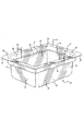
図1に、本発明の医療用器具パッケージが10で全体的に示されている。医療用器具パッケージ10は、槽20と蓋60を含んでいる。図1と図4に関して、槽20は、4つの壁24,26,28,30がそれからほぼ90度上向きに延びている、平坦な底22を備えている。4つの壁24,26,28,30は、第1の外向き延伸フランジ34を成形すべく、上端32で終端している。第1のフランジは、壁の上端32にほぼ90度で交わり、そこから外向きに延びている。第1の外向き延伸フランジ34の外縁36からほぼ90度に上向きに、4つの上部壁38,40,42,44が存在する。4つの上部壁38,40,42および44は、第2の外向き延伸フランジ48を成形すべく、第2の上端46で終端している。第2の外向き延伸フランジ48は、第2の上端46にほぼ90度で交わり、そこから外向きに延びている。第2の外向き延伸フランジは、蓋60を槽20に搭載または接着するために、上面50を備えている。
【0023】
第1のフランジ34と第2のフランジ48との間の垂直の距離によって規定されるギャップ52は、内部保持器具(interior holding apparatus)の使用のための領域を提供している。そのような器具は、内容物、例えば注射器を保持し、またパッケージの内容物の空間的な配置を維持することができる。ギャップ52はまた、自動化されたオープニングツールが槽20の内容物に触れたり損傷するおそれなく使用されるための深さを提供する。
【0024】
第1のフランジ34と第2のフランジ48との間の、水平のまたは外向きの距離は、第2のギャップ54を規定する。槽20の内容物は、4つの壁24,26,28,30により規定される空間56の内側に収容され、また第1のフランジ34の内側にある。ギャップ54は、槽20の内容物のダメージを避けるためにホットナイフやレーザーカッターのような自動化されたオープニングツールを使用するときに、ギャップ52と同様にバッファーゾーンを提供する。
【0025】
槽20は好ましくは、可視光および紫外光の透過を許容するプラスチック樹脂から成形される。可視光のみを透過する好適な材料の例は、高メルトフローのポリカーボネートおよび高メルトフローのコポリエステルであり、それらはまた、良好な衝撃剛性と総合的な耐久性を示す。本発明において特に好ましい樹脂は、可視光と紫外光の両者を透過し且つ槽の内容物の良好な機械的保護を提供するメチルペンテンコポリマーである。具体的には、メチルペンテンコポリマーは、254ナノメートルの微生物殺菌紫外線波長において良好な透過性を発揮する。
【0026】
槽20は、好ましくは射出成形プロセスまたは反応射出成形プロセスを利用して成形される。射出成形プロセスでは、樹脂は指定の温度と圧力で型の中へと射出され、固形の物体を成形すべく硬化される。
【0027】
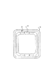
本発明の槽20は、好ましくは、製造の間に型から槽20を取り去るのを容易にするために、外側と内側の両方に、丸みをつけられたコーナー58を備える。丸みをつけられたコーナー58はまた、槽20の内容物にダメージを引き起こしたりまた槽20を扱う人に怪我の脅威をもたらすような鋭いエッジの成形を防ぐ。槽20はまた、製造の間に型から槽20を取り除くのを助長するために、図4および5に示されるように、異形部分(contoured portion)59を備えていてもよい。
【0028】
本発明の蓋60は、気体透過可能なマイクロファイバーの中央部分62および、中央部分62にその周縁66に沿って取り付けられた透明プラスチックフィルム64を含んでいる。
【0029】
中央部分62は、好ましくは、デラウェア州ウィルミントンのE.I.Dupont de Nemours and Companyによって製造されるポリオレフィンのマイクロファイバー材料のTyvek(登録商標)を含む。さらにより具体的には、中央部分62はコートされていない(uncoated)Tyvek(登録商標)1073Bを含む。
【0030】
透明プラスチックフィルム64は、中央部分66の周縁に沿って、接着剤、糊または他の接着性物質を使って取り付けられ、または熱融着されてもよい。透明プラスチックフィルム64は、二つの部材の適切な接着を保証するために、少なくとも5ミリメートルだけ中央部分にオーバーラップ68しなければならない。
【0031】
透明のフィルム64の幅は、それが関連させられる適用に依存して可変である。例えば、もし蓋60が剥き取り操作(peel-away procedure)によって手作業で取り去られるのであれば、10〜20ミリメートルの狭い幅が用いられてもよい。その10〜20ミリメートルの幅は、熱シールのすぐ外側の領域を殺菌するために十分な光が入るのを許容するが、しかし経済的な見とおしから過剰に幅広ではない。もし蓋60が、自動化された開封処理のような代替の適用において使用されようとするならば、中央部分のせん断を裂けるためにより広い幅が用いられ、それによって粒状物質が生じる。透明フィルム64の好ましい幅は、自動化された処理のために、20〜30ミリメートルの範囲内である。
【0032】
フィルム64は、表面除染処理のために、紫外スペクトルの光の透過を許容しなければならない。フィルム64はまた、偶発的な裂けに抵抗するために十分なせん断強さを備えなければならず、しかし自動化されたシステムを用いた容易な開操作が可能でなければならない。
【0033】
本発明は関連する法基準に従って記述されており、よって先行する記述は本質的に限定するものではなく例示である。開示された実施形態に対する変更および改変は当業者に明白となりうる。したがって、本発明に与えられる法的保護の範囲は以下の請求範囲の検討によってのみ決定されうる。
【図面の簡単な説明】
【図1】 本発明の医療用器具パッケージの斜視図である。
【図2】 本発明の医療用器具パッケージの断面図である。
【図3】 本発明の医療用器具パッケージのコーナーの平面図である。
【図4】 本発明の槽の斜視図である。
【図5】 本発明の槽の平面図であり、型からの槽の解放を促進する異形部を示す。[0001]
(Technical field of the invention)
The present invention relates to a medical instrument package. More particularly, the present invention relates to a medical instrument package having a gas permeable lid and a transparent plastic tank.
[0002]
(Background of the Invention)
Medical instruments such as prefillable syringes and the like are often packaged in multi-unit packages, which can be filled with drugs or otherwise manipulated before use or surgical procedures. The surface must be decontaminated before being introduced into a controlled sterilization environment, such as that used in
[0003]
There are a number of methods used to sterilize instruments in a package, such as gas sterilization using ethylene oxide or steam sterilization. However, different methods, such as ultraviolet light sterilization, are often used to decontaminate the surface of the package prior to subsequent use. It would be desirable to have a medical instrument package that can be used in a number of sterilization and decontamination techniques to obtain a high level of microbial sterilization.
[0004]
A common type of package used in the field of medical packaging is the “peel-open” package. Such packages typically consist of a thermoplastic film formed into the desired packaging shape, and the lid is then sealed to the plastic film to accommodate the product to be packaged.
[0005]
Because the film does not provide sufficient protective properties for use in multi-unit packages that can accommodate delicate items, the above-described general thermoplastic film package is suitable for packaging individual medical devices. Often used. Therefore, there is a need for a multi-unit package such as a bath that can withstand the sterilization and decontamination process and provide a sufficient mechanical barrier to avoid damaging the items held in the package. To do.
[0006]
The lid material used is a nonwoven fiber tailored to provide a microporous structure, such as Tyvek®. Microporous fiber conditioning allows the gas to penetrate but has a pore size that is small enough to block microbial transmission.
[0007]
The microporous fibers disposed in the lid are therefore useful in sterilization techniques such as the ethylene oxide and steam sterilization techniques described above.
[0008]
The Tyvek® lid, however, does not allow the transmission of ultraviolet light that may be used as a packaging surface decontamination technique. Specifically, the heat seal between the lid and the tank is a Tyvek during peel-off if manufacturing constraints and a Tyvek® unsealed edge for initiation of the stripping process are not obtained. Due to the possibility of (R) tearing, it cannot be fitted snugly to the edge of the tank flange. Therefore, there is an area that is covered by Tyvek® and that is outside the heat seal, and that area is not kept sterile with the contents of the package. This area can also be detoured during package operation, as can be the case for the entire outer surface of the package. However, unlike the remaining exterior surfaces that can be directly exposed to ultraviolet light for decontamination, the exterior of the heat seal is made up of an opaque Tyvek® material on the top surface and an opaque bath material below. Blocked from ultraviolet light.
[0009]
Therefore, it is desirable to use an ultraviolet light permeable plastic tank that allows the transmission of light to the underside of the heat seal between the lid and the tank to disinfect all the microorganisms present inside. . Plastics that transmit light in the ultraviolet region generally transmit a larger percentage of incident light in the visible (400-700 nanometer) region, resulting in a transparent appearance.
[0010]
One advantage of using a transparent plastic bath over opaque is that it visually inspects the contents of the package to determine if any of the items are damaged. Is to make it possible. This aspect provides the manufacturer with quality control benefits in addition to allowing the end user to verify that he has not received or used damaged items. Another advantage of using a transparent plastic bath is the possibility of using an automated visual quality system. For example, the package and its contents can be compared with a captured and stored visual image to determine if the contents of the package are damaged. Such an automated system may provide cost savings in addition to enhanced quality control efficiency.
[0011]
Instead, a Tyvek® lid with an ultraviolet light transmissive plastic boundary heat sealed to the plastic bath allows for photodisinfection of the area between the lid and the bath. Such a lid can be used with either a transparent plastic tank or an opaque tank, allowing light to pass through the area around the heat seal.
[0012]
Another previously known problem associated with Tyvek® lids is that the Tyvek® lid tears or tears when peeled off to open the package, and thus the contents of the package To produce an unacceptable particulate material that can contaminate.
[0013]
Tyvek® lids are used as an attempt to avoid splitting or tearing into thin layers when the strength of the heat seal between the lid and the tank is too great, and to reduce particle formation. It is known to coat. The disadvantage of this coating technology is that it tends to reduce the size of the Tyvek® pores, thereby hindering the necessary transmission of gas across the lid material and increasing the cycle time of the sterilization operation .
[0014]
A gas permeable uncoated Tyvek® lid with a smooth, continuous plastic boundary that resists tearing and does not produce particulate material when peeled to access the contents It is desirable to have.
[0015]
A smooth, continuous plastic border lid is an alternative to peel-off technology, automated lid removal, such as a hot knife or laser cutter that cuts the plastic border inside the heat seal area It is also desirable to use it with a system.
[0016]
(Summary of the Invention)
Therefore, it is an object of the present invention to provide a medical device having a UV transparent and transparent plastic tank that allows visual inspection of the contents and allows light to disinfect microorganisms. Is to provide a package.
[0017]
Another object of the present invention is to provide a medical device package having a clear plastic reservoir with sufficient strength properties to hold the package contents and protect them from damage.
[0018]
Another object of the present invention is to provide a medical device package having a microporous gas permeable lid with a plastic border to minimize the formation of particulate material when the package is opened.
[0019]
Another object of the present invention is to provide a medical device package having a microporous gas permeable lid with an ultraviolet transmissive plastic boundary to allow light transmission during the decontamination process. It is to be.
[0020]
The present invention meets these objectives by providing a medical device package with a four-sided bottom basin having four walls extending upwardly at approximately 90 degrees therefrom. The walls terminate in a first flange that extends outward from the four walls at approximately 90 degrees. The first flange terminates in four upper walls that extend upward at approximately 90 degrees from the flange. The four upper walls terminate in a second outwardly extending flange that extends approximately 90 degrees from the four upper walls. The bath, this is such to withstand exposure to sterilization and surface decontamination process gas without degradation, it is formed by ultraviolet light transmitting plastic.
[0021]
The present invention also includes a gas permeable central portion, a tank and a transparent plastic film that is attach along its periphery to the central portion. Plastic film, in order to ensure coupling two trusted member, overlaps the central portion when attached Installing. Transparent plastic films have a high shear resistance to avoid the formation of particulate material when an opening force is applied. The transparent plastic film also allows transmission of ultraviolet light. These and other features of the invention can be better understood from the following description and drawings.
[0022]
(Detailed description of preferred embodiments)
In FIG. 1, a medical device package of the present invention is generally indicated at 10. The medical instrument package 10 includes a tank 20 and a lid 60. With reference to FIGS. 1 and 4, the tub 20 has a flat bottom 22 from which four
[0023]
A gap 52 defined by the vertical distance between the first flange 34 and the second flange 48 provides an area for the use of an interior holding apparatus. Such a device can hold the contents , such as a syringe, and maintain the spatial arrangement of the contents of the package. Gap 52 also provides a depth for the automated opening tool is a possibility that Ku use damaging or touching the contents of the vessel 20.
[0024]
The horizontal or outward distance between the first flange 34 and the second flange 48 defines a second gap 54. The contents of the tub 20 are housed inside a space 56 defined by the four
[0025]
The vessel 20 is preferably molded from a plastic resin that allows transmission of visible and ultraviolet light. Examples of suitable materials that transmit only visible light are high melt flow polycarbonates and high melt flow copolyesters, which also exhibit good impact stiffness and overall durability. A particularly preferred resin in the present invention is a methylpentene copolymer that transmits both visible and ultraviolet light and provides good mechanical protection of the contents of the vessel. Specifically, the methylpentene copolymer exhibits good permeability at a microbial germicidal UV wavelength of 254 nanometers.
[0026]
The tank 20 is preferably molded using an injection molding process or a reaction injection molding process. In the injection molding process, the resin is injected into a mold at a specified temperature and pressure and cured to form a solid object.
[0027]
The bath 20 of the present invention preferably includes rounded corners 58 on both the outside and the inside to facilitate removal of the bath 20 from the mold during manufacture. The rounded corner 58 also prevents the formation of sharp edges that cause damage to the contents of the tub 20 or pose a threat of injury to the person handling the tub 20. The vessel 20 may also include a contoured portion 59, as shown in FIGS. 4 and 5, to assist in removing the vessel 20 from the mold during manufacture.
[0028]
The lid 60 of the present invention comprises a
[0029]
The
[0030]
The transparent plastic film 64 may be attached or heat fused along the periphery of the central portion 66 using an adhesive, glue or other adhesive material. The transparent plastic film 64 must overlap the central portion 68 by at least 5 millimeters to ensure proper adhesion of the two members .
[0031]
The width of the transparent film 64 is variable depending on the application with which it is associated. For example, if the lid 60 is manually removed by a peel-away procedure, a narrow width of 10-20 mm may be used. Its 10-20 millimeter width allows enough light to enter the area just outside the heat seal, but is not overly wide from an economic perspective. If the lid 60 is to be used in alternative applications such as an automated opening process, a wider width is used to tear the shear in the central portion, thereby producing a particulate material. The preferred width of the transparent film 64 is in the range of 20-30 millimeters for automated processing.
[0032]
The film 64 must allow transmission of light in the ultraviolet spectrum for surface decontamination processing. The film 64 must also have sufficient shear strength to resist accidental tearing, but it must be capable of easy opening using an automated system.
[0033]
The present invention has been described in accordance with the relevant legal standards, and thus the preceding description is exemplary rather than limiting in nature. Changes and modifications to the disclosed embodiments will be apparent to those skilled in the art. Accordingly, the scope of legal protection afforded this invention can only be determined by studying the following claims.
[Brief description of the drawings]
FIG. 1 is a perspective view of a medical instrument package of the present invention.
FIG. 2 is a cross-sectional view of the medical device package of the present invention.
FIG. 3 is a plan view of a corner of the medical instrument package of the present invention.
FIG. 4 is a perspective view of the tank of the present invention.
FIG. 5 is a plan view of the tank of the present invention, showing a profile that facilitates the release of the tank from the mold.
Claims (27)
4側の底を有する槽と、
前記底に交わり、それから上向きに延びる4つの壁と
を備え、これら4つの壁は当該4つの壁から側方に延びる第1の外向き延伸フランジで終端し、この第1の外向き延伸フランジは4つの上部壁で終端し、これら4つの上部壁は前記第1の外向き延伸フランジからほぼ90度で延びて第2の外向き延伸フランジで終端し、この第2の外向き延伸フランジは前記4つの上部壁から約90度で延び、
前記槽は、これが劣化することなく蒸気およびエチレンオキシドの滅菌環境への曝露に耐え得る透明のプラスチックから形成されており、このプラスチックは、前記槽内の医療用器具の滅菌のために前記槽の前記壁を介した紫外光の通過を許容し、
プラスチックフィルムの縁に囲まれた気体透過可能な中央部分を含む蓋をさらに備え、前記中央部分はこの蓋を介した消毒性の気体の通過を許容し、前記プラスチックフィルムは紫外光の通過を許容し且つ前記第2の外向き延伸フランジと密封結合していることを特徴とする医療用器具パッケージ。A medical instrument package,
A tank having a bottom on four sides;
Intersects the bottom, then the four walls extending upwardly
The provided, these four walls terminates at the first outward extending flange extending laterally from this the four walls, the first outward extending flange terminates in four upper walls, these four upper the wall terminates at the second outward extending flange extending at approximately 90 degrees from the first outward extending flange, the second outward extending flange extends at about 90 degrees from the four top walls,
The vessel, which is formed of a transparent plastic capable of withstanding exposure to rather steam and ethylene oxide sterilization environments being degraded, the plastic, the said tank for sterilization of medical instruments in the inner tub Allow the passage of ultraviolet light through the wall,
Further comprising a lid comprising an edge gas permeable central portion surrounded by a plastic film, wherein the central portion allows the passage of disinfection of gases through the lid, the plastic film allows passage of ultraviolet light and said second medical instrument package, characterized in the Turkey have sealed combined with an outward extending flange and.
前記蓋は気体透過可能な中央部分を有し、
透明のプラスチックフィルムが前記中央部分の周縁に沿って前記中央部分に取り付けられ、このプラスチックフィルムは前記中央部分に重なり、当該透明のプラスチックフィルムは力が加えられた場合に粒子状物質の発生を回避できるせん断抵抗を有し、該透明のプラスチックフィルムはその下方の前記槽の領域を除染または滅菌すべく紫外波長の光の透過を許容することを特徴とする医療用器具パッケージ。 A medical instrument package comprising a lid and a tub ,
The lid will have a gas permeable central portion,
The plastic film of the transparent central portion periphery the Ri attached et been taken in the central portion along the, the plastic film overlaps the central portion, the plastic film of the transparent particulate matter when a force is applied has a shear resistance that can avoid the occurrence, medical instrument packaging plastic film of the transparent, characterized in that to permit the transmission of light in the ultraviolet wavelengths in order to decontaminate or sterilize the area of the vessel under side of its .
a.底、側壁および上部壁を備える槽であって、前記側壁は前記底に交わると共に第1のフランジで終端し、前記上部壁は前記第1のフランジから延びて第2のフランジで終端する槽と、
b.前記第2のフランジに搭載される蓋であって、気体透過可能な中央部分およびこの中央部分に取り付けられる透明のプラスチックフィルムを備える蓋と
を備え、前記透明のプラスチックフィルムは、前記中央部分の周縁に沿って前記中央部分に取り付けられ、このプラスチックフィルムは前記中央部分と重なり、当該透明のプラスチックフィルムは力が加えられた場合に粒子状物質の発生を回避できるせん断抵抗を有し、該透明のプラスチックフィルムはその下方の前記槽の領域を除染または滅菌すべく紫外波長の光の透過を許容することを特徴とする医療用器具パッケージ。A medical instrument package,
a. Bottom, a tank having side walls and a top wall, the tank side wall terminates at a first flange Rutotomoni Majiwa to said bottom, said top wall terminating in a second flange extending from said first flange And
b. A lid mounted to said second flange, and a lid with a plastic film transparent attached to the central portion of the gas permeable central portion and this plastic film of the transparent, of said central portion Attached to the central portion along the periphery, the plastic film overlaps the central portion, and the transparent plastic film has a shear resistance that can avoid the generation of particulate matter when a force is applied, the transparent film The medical instrument package is characterized in that the plastic film allows transmission of light of ultraviolet wavelength so as to decontaminate or sterilize the region of the tank below the plastic film.
4側の底および4つの壁を有する槽であって、前記4つの壁が前記底に交わると共に第1の外向き延伸フランジで終端し、この第1の横向き延伸フランジが前記4つの壁から側方に延び、4つの上部壁が前記第1の外向き延伸フランジからほぼ90度で延びて第2の外向き延伸フランジで終端し、この第2の外向き延伸フランジが前記4つの上部壁からほぼ90度で伸びる槽を提供するステップと、
医療用器具を前記槽に挿入するステップと、
前記第2のフランジと密封結合するプラスチックフィルムを含み、かつ気体透過可能な中央部分を含む蓋で前記槽を密封するステップと、
前記槽を介して紫外光を透過させ、これによって前記医療用器具を除染するステップと、
前記槽に密封結合している前記蓋の前記プラスチックフィルムを介して、紫外光を透過させるステップと
を含むことを特徴とする方法。A method of storing and sanitizing medical equipment,
A vessel having a 4 side of the bottom and four walls, from the four walls terminate at Rutotomoni first outward extending flange Majiwa to the bottom, the first transverse stretching flange the four walls extends laterally, four top walls terminating at a second outwardly extending flange extending at approximately 90 degrees from the first outward extending flange, the second outward extending flange the four upper walls providing a vessel extending at approximately 90 degrees from,
Inserting a medical instrument into the vessel,
A step of sealing the tank a plastic film that seals coupled to the second flange seen including, and a gas permeable central part including a lid,
A step to transmit ultraviolet light, thereby decontaminating the medical instrument through the vessel,
Through the plastic film of said lid that sealingly coupled to said tank, wherein the containing <br/> the step of transmitting ultraviolet light.
Applications Claiming Priority (3)
| Application Number | Priority Date | Filing Date | Title |
|---|---|---|---|
| US71668700A | 2000-11-20 | 2000-11-20 | |
| US09/716,619 US6629602B1 (en) | 2000-11-20 | 2000-11-20 | Clear medical packaging |
| PCT/US2001/043234 WO2002042164A2 (en) | 2000-11-20 | 2001-11-20 | Clear medical packaging |
Publications (2)
| Publication Number | Publication Date |
|---|---|
| JP2004514476A JP2004514476A (en) | 2004-05-20 |
| JP4237489B2 true JP4237489B2 (en) | 2009-03-11 |
Family
ID=27109572
Family Applications (1)
| Application Number | Title | Priority Date | Filing Date |
|---|---|---|---|
| JP2002544312A Expired - Lifetime JP4237489B2 (en) | 2000-11-20 | 2001-11-20 | Transparent medical packaging |
Country Status (7)
| Country | Link |
|---|---|
| EP (2) | EP2070488B1 (en) |
| JP (1) | JP4237489B2 (en) |
| AT (1) | ATE383119T1 (en) |
| AU (1) | AU2002217777A1 (en) |
| DE (1) | DE60132352T2 (en) |
| ES (2) | ES2449770T3 (en) |
| WO (1) | WO2002042164A2 (en) |
Cited By (4)
| Publication number | Priority date | Publication date | Assignee | Title |
|---|---|---|---|---|
| WO2013175997A1 (en) | 2012-05-21 | 2013-11-28 | 株式会社エアレックス | Electronic beam irradiation device |
| JP2016129677A (en) * | 2016-01-22 | 2016-07-21 | 株式会社エアレックス | Electron beam sterilization method |
| KR20180012257A (en) | 2015-05-27 | 2018-02-05 | 가부시키가이샤 에아렉크스 | Electron beam irradiator |
| KR20230074061A (en) | 2020-09-24 | 2023-05-26 | 가부시키가이샤 에아렉크스 | continuous decontamination device |
Families Citing this family (12)
| Publication number | Priority date | Publication date | Assignee | Title |
|---|---|---|---|---|
| ES2222952T3 (en) * | 2001-06-13 | 2005-02-16 | Getinge Skarhamn Ab | DEVICE FOR AN AUTOCLAVE. |
| US8415262B2 (en) | 2003-10-22 | 2013-04-09 | E I Du Pont De Nemours And Company | Porous fibrous sheets of nanofibers |
| EP1559655A1 (en) * | 2004-01-29 | 2005-08-03 | Impress Group B.V. | Container and method for producing such a container |
| US7743811B2 (en) | 2006-09-21 | 2010-06-29 | Ulma Packaging Technological Center, S. Coop. | Sheet for closing aseptic containers, aseptic container comprising said sheet, and equipment and method for obtaining said container |
| JP5603700B2 (en) * | 2010-07-30 | 2014-10-08 | 株式会社エアレックス | Continuous decontamination, sterilization apparatus and method |
| DE102012111624A1 (en) | 2012-05-03 | 2013-11-07 | Schott Ag | Process for treating or processing containers for medical or pharmaceutical applications and carriers and transport or packaging containers therefor |
| EP2684803B1 (en) | 2012-07-11 | 2014-09-10 | Multivac Sepp Haggenmüller GmbH & Co. KG | Method for manufacturing a packaging |
| US10293965B2 (en) * | 2015-05-27 | 2019-05-21 | Becton, Dickinson And Company | Packaging method to enable re-sterilization of medical device |
| JP2018102635A (en) * | 2016-12-27 | 2018-07-05 | 株式会社トクヤマ | Sterilization method, and sterilizer |
| CN107648628A (en) * | 2017-10-30 | 2018-02-02 | 郑州仁宏医药科技有限公司 | A kind of Medical appliance decontaminating apparatus with store function |
| FR3088624A1 (en) * | 2018-11-15 | 2020-05-22 | Claranor | STERILIZED PACKAGING, PARTICULARLY FOR THE PHARMACEUTICAL INDUSTRY |
| US20210338860A1 (en) | 2020-05-01 | 2021-11-04 | Uv Innovators, Llc | Ultraviolet (uv) light emission device employing visible light for operation guidance, and related methods of use, particularly suited for decontamination |
Family Cites Families (6)
| Publication number | Priority date | Publication date | Assignee | Title |
|---|---|---|---|---|
| DE2952733A1 (en) | 1979-12-29 | 1981-07-02 | Karl-Heinz Dr. 4802 Halle Sengewald | Sterilisable medicine package - with hole in deep drawn plastics pack bottom sealed by welded fibre foil disc |
| US4402407A (en) * | 1980-12-16 | 1983-09-06 | Maly George P | Sterilization chest |
| DE3637687A1 (en) | 1986-11-05 | 1988-05-19 | Basf Ag | CONTAINER FOR MEDICAL MATERIAL |
| US5379895A (en) * | 1993-09-13 | 1995-01-10 | Minnesota Mining And Manufacturing Company | Package for surgical device |
| JPH10151160A (en) * | 1996-11-22 | 1998-06-09 | Ushio Inc | Clean hood system |
| AR024246A1 (en) * | 1999-03-01 | 2002-09-25 | Johnson & Johnson Vision Care | CONTAINER FOR MEDICAL DEVICE. |
-
2001
- 2001-11-20 ES ES08000207.4T patent/ES2449770T3/en not_active Expired - Lifetime
- 2001-11-20 ES ES01997438T patent/ES2298296T3/en not_active Expired - Lifetime
- 2001-11-20 DE DE60132352T patent/DE60132352T2/en not_active Expired - Lifetime
- 2001-11-20 JP JP2002544312A patent/JP4237489B2/en not_active Expired - Lifetime
- 2001-11-20 AU AU2002217777A patent/AU2002217777A1/en not_active Abandoned
- 2001-11-20 AT AT01997438T patent/ATE383119T1/en not_active IP Right Cessation
- 2001-11-20 EP EP08000207.4A patent/EP2070488B1/en not_active Expired - Lifetime
- 2001-11-20 EP EP01997438A patent/EP1339342B1/en not_active Expired - Lifetime
- 2001-11-20 WO PCT/US2001/043234 patent/WO2002042164A2/en active IP Right Grant
Cited By (4)
| Publication number | Priority date | Publication date | Assignee | Title |
|---|---|---|---|---|
| WO2013175997A1 (en) | 2012-05-21 | 2013-11-28 | 株式会社エアレックス | Electronic beam irradiation device |
| KR20180012257A (en) | 2015-05-27 | 2018-02-05 | 가부시키가이샤 에아렉크스 | Electron beam irradiator |
| JP2016129677A (en) * | 2016-01-22 | 2016-07-21 | 株式会社エアレックス | Electron beam sterilization method |
| KR20230074061A (en) | 2020-09-24 | 2023-05-26 | 가부시키가이샤 에아렉크스 | continuous decontamination device |
Also Published As
| Publication number | Publication date |
|---|---|
| JP2004514476A (en) | 2004-05-20 |
| ATE383119T1 (en) | 2008-01-15 |
| EP2070488A1 (en) | 2009-06-17 |
| EP1339342A2 (en) | 2003-09-03 |
| DE60132352T2 (en) | 2008-12-24 |
| WO2002042164A2 (en) | 2002-05-30 |
| WO2002042164A3 (en) | 2003-02-13 |
| DE60132352D1 (en) | 2008-02-21 |
| ES2449770T3 (en) | 2014-03-21 |
| EP1339342B1 (en) | 2008-01-09 |
| AU2002217777A1 (en) | 2002-06-03 |
| EP2070488B1 (en) | 2014-01-08 |
| ES2298296T3 (en) | 2008-05-16 |
Similar Documents
| Publication | Publication Date | Title |
|---|---|---|
| US6629602B1 (en) | Clear medical packaging | |
| JP4237489B2 (en) | Transparent medical packaging | |
| KR100877237B1 (en) | Package for products to be sterilised with a high-temperature sterilising fluid | |
| US8056719B2 (en) | Multipurpose packages for sterile products or products to be sterilized | |
| JP5547209B2 (en) | Single use sterilization container | |
| KR100847333B1 (en) | Package for sterile products | |
| US10987186B2 (en) | Sterilization packaging systems | |
| US5971152A (en) | Container with reinforced tab and method | |
| JP2022155515A (en) | Package, method and application | |
| JP2001240099A (en) | Sterilized article housing container |
Legal Events
| Date | Code | Title | Description |
|---|---|---|---|
| A621 | Written request for application examination |
Free format text: JAPANESE INTERMEDIATE CODE: A621 Effective date: 20041119 |
|
| A131 | Notification of reasons for refusal |
Free format text: JAPANESE INTERMEDIATE CODE: A131 Effective date: 20071225 |
|
| A521 | Request for written amendment filed |
Free format text: JAPANESE INTERMEDIATE CODE: A523 Effective date: 20080325 |
|
| A131 | Notification of reasons for refusal |
Free format text: JAPANESE INTERMEDIATE CODE: A131 Effective date: 20080801 |
|
| A521 | Request for written amendment filed |
Free format text: JAPANESE INTERMEDIATE CODE: A523 Effective date: 20081104 |
|
| TRDD | Decision of grant or rejection written | ||
| A01 | Written decision to grant a patent or to grant a registration (utility model) |
Free format text: JAPANESE INTERMEDIATE CODE: A01 Effective date: 20081128 |
|
| A01 | Written decision to grant a patent or to grant a registration (utility model) |
Free format text: JAPANESE INTERMEDIATE CODE: A01 |
|
| A61 | First payment of annual fees (during grant procedure) |
Free format text: JAPANESE INTERMEDIATE CODE: A61 Effective date: 20081218 |
|
| R150 | Certificate of patent or registration of utility model |
Free format text: JAPANESE INTERMEDIATE CODE: R150 Ref document number: 4237489 Country of ref document: JP Free format text: JAPANESE INTERMEDIATE CODE: R150 |
|
| FPAY | Renewal fee payment (event date is renewal date of database) |
Free format text: PAYMENT UNTIL: 20111226 Year of fee payment: 3 |
|
| FPAY | Renewal fee payment (event date is renewal date of database) |
Free format text: PAYMENT UNTIL: 20121226 Year of fee payment: 4 |
|
| R250 | Receipt of annual fees |
Free format text: JAPANESE INTERMEDIATE CODE: R250 |
|
| FPAY | Renewal fee payment (event date is renewal date of database) |
Free format text: PAYMENT UNTIL: 20121226 Year of fee payment: 4 |
|
| FPAY | Renewal fee payment (event date is renewal date of database) |
Free format text: PAYMENT UNTIL: 20131226 Year of fee payment: 5 |
|
| R250 | Receipt of annual fees |
Free format text: JAPANESE INTERMEDIATE CODE: R250 |
|
| R250 | Receipt of annual fees |
Free format text: JAPANESE INTERMEDIATE CODE: R250 |
|
| R250 | Receipt of annual fees |
Free format text: JAPANESE INTERMEDIATE CODE: R250 |
|
| R250 | Receipt of annual fees |
Free format text: JAPANESE INTERMEDIATE CODE: R250 |
|
| R250 | Receipt of annual fees |
Free format text: JAPANESE INTERMEDIATE CODE: R250 |
|
| R250 | Receipt of annual fees |
Free format text: JAPANESE INTERMEDIATE CODE: R250 |
|
| R250 | Receipt of annual fees |
Free format text: JAPANESE INTERMEDIATE CODE: R250 |
|
| R250 | Receipt of annual fees |
Free format text: JAPANESE INTERMEDIATE CODE: R250 |
|
| R250 | Receipt of annual fees |
Free format text: JAPANESE INTERMEDIATE CODE: R250 |
|
| EXPY | Cancellation because of completion of term |