JP4233523B2 - Method and apparatus for sensing permanent state deviation - Google Patents
Method and apparatus for sensing permanent state deviation Download PDFInfo
- Publication number
- JP4233523B2 JP4233523B2 JP2004515286A JP2004515286A JP4233523B2 JP 4233523 B2 JP4233523 B2 JP 4233523B2 JP 2004515286 A JP2004515286 A JP 2004515286A JP 2004515286 A JP2004515286 A JP 2004515286A JP 4233523 B2 JP4233523 B2 JP 4233523B2
- Authority
- JP
- Japan
- Prior art keywords
- band
- coil
- amorphous
- deviation
- sensing
- Prior art date
- Legal status (The legal status is an assumption and is not a legal conclusion. Google has not performed a legal analysis and makes no representation as to the accuracy of the status listed.)
- Expired - Lifetime
Links
Images


Classifications
-
- G—PHYSICS
- G01—MEASURING; TESTING
- G01P—MEASURING LINEAR OR ANGULAR SPEED, ACCELERATION, DECELERATION, OR SHOCK; INDICATING PRESENCE, ABSENCE, OR DIRECTION, OF MOVEMENT
- G01P15/00—Measuring acceleration; Measuring deceleration; Measuring shock, i.e. sudden change of acceleration
- G01P15/02—Measuring acceleration; Measuring deceleration; Measuring shock, i.e. sudden change of acceleration by making use of inertia forces using solid seismic masses
- G01P15/08—Measuring acceleration; Measuring deceleration; Measuring shock, i.e. sudden change of acceleration by making use of inertia forces using solid seismic masses with conversion into electric or magnetic values
- G01P15/0885—Measuring acceleration; Measuring deceleration; Measuring shock, i.e. sudden change of acceleration by making use of inertia forces using solid seismic masses with conversion into electric or magnetic values by magnetostrictive pick-up
-
- G—PHYSICS
- G01—MEASURING; TESTING
- G01H—MEASUREMENT OF MECHANICAL VIBRATIONS OR ULTRASONIC, SONIC OR INFRASONIC WAVES
- G01H11/00—Measuring mechanical vibrations or ultrasonic, sonic or infrasonic waves by detecting changes in electric or magnetic properties
- G01H11/02—Measuring mechanical vibrations or ultrasonic, sonic or infrasonic waves by detecting changes in electric or magnetic properties by magnetic means, e.g. reluctance
- G01H11/04—Measuring mechanical vibrations or ultrasonic, sonic or infrasonic waves by detecting changes in electric or magnetic properties by magnetic means, e.g. reluctance using magnetostrictive devices
-
- G—PHYSICS
- G01—MEASURING; TESTING
- G01B—MEASURING LENGTH, THICKNESS OR SIMILAR LINEAR DIMENSIONS; MEASURING ANGLES; MEASURING AREAS; MEASURING IRREGULARITIES OF SURFACES OR CONTOURS
- G01B7/00—Measuring arrangements characterised by the use of electric or magnetic techniques
- G01B7/16—Measuring arrangements characterised by the use of electric or magnetic techniques for measuring the deformation in a solid, e.g. by resistance strain gauge
- G01B7/24—Measuring arrangements characterised by the use of electric or magnetic techniques for measuring the deformation in a solid, e.g. by resistance strain gauge using change in magnetic properties
-
- G—PHYSICS
- G01—MEASURING; TESTING
- G01L—MEASURING FORCE, STRESS, TORQUE, WORK, MECHANICAL POWER, MECHANICAL EFFICIENCY, OR FLUID PRESSURE
- G01L1/00—Measuring force or stress, in general
- G01L1/12—Measuring force or stress, in general by measuring variations in the magnetic properties of materials resulting from the application of stress
-
- B—PERFORMING OPERATIONS; TRANSPORTING
- B82—NANOTECHNOLOGY
- B82Y—SPECIFIC USES OR APPLICATIONS OF NANOSTRUCTURES; MEASUREMENT OR ANALYSIS OF NANOSTRUCTURES; MANUFACTURE OR TREATMENT OF NANOSTRUCTURES
- B82Y40/00—Manufacture or treatment of nanostructures
Description
本発明は、例えば、プロトタイプ試験、企業内既存生産装置など、ハードウェア設計及び構造に対して重要な部分におけるリアルタイムの一時的な内部材料振動を検知することによって永久状態偏差を感知及び表示、及び/または監視することによって予め構築されたインフラ設備を維持するための方法及び装置に関する。 The present invention senses and displays permanent state deviations by detecting real-time temporary internal material vibrations in critical parts of the hardware design and structure, for example, prototype testing, in-house production equipment, and the like, and And / or to a method and apparatus for maintaining pre-built infrastructure equipment by monitoring.
近年のマイクロ電子技術分野の発展、とりわけますます強化されるコンピュータに関するメモリーの発展は、製品設計における寸法に重要な大きさを測定することを対象とした加速計、曲げ/変形表示計、アコースティックエミッション用インジケータなどのトランスデューサあるいはセンサが市場において異なる型を生じることによりそれらの組立てが過度に複雑化され、その結果として、過度に場所をとり、更に、近代的なハードウェア設計がますます要求され、とりわけ近代的なソフトウェアが使用可能な程度まで応用するのにコストがかかることを伴ってきた。 Recent developments in the field of microelectronics, especially the development of memory related to increasingly powerful computers, include accelerometers, bend / deformation indicators, and acoustic emissions aimed at measuring critical dimensions in product design. The assembly of transducers or sensors such as industrial indicators in the market is overly complicated, resulting in excessive space and further demands for modern hardware designs, In particular, it has been associated with the cost of applying modern software to the extent that it can be used.
したがって、本発明の主要な目的の1つは、原理上非常に簡潔なトランスデューサエレメントあるいはセンサ及びそれらの配置を実現することにより、その組立てにおいて場所を節約することができるため、従来では想像できないトランスデューサあるいはセンサ構造を実現し、同時に、これまで可能だった範囲より広い範囲に対する感度及び精度をかなり増大させた測定が可能となり、その上、従来ではほとんど検知できなかった大きさの測定が可能となる機会を与えることである。本発明の別の目的は非常に小さい固有の質量を有することにより、その検知される対象物の大きさが、これにより影響されないようなセンサ配置を実現することである。 Thus, one of the main objectives of the present invention is to realize a transducer element or sensor which is very simple in principle and their arrangement, thus saving space in its assembly and thus a transducer that is not conceivable in the past. Alternatively, the sensor structure can be realized, and at the same time, measurement with significantly increased sensitivity and accuracy over a wider range than previously possible is possible. Is to give an opportunity. Another object of the present invention is to achieve a sensor arrangement that has a very small intrinsic mass so that the size of the detected object is not affected thereby.
上記に概略した目的は、付属品に添加される高導磁性及び比較的高い磁気歪みを有する1つ以上の少なくとも約20μmの厚さの非晶形あるいはナノ結晶性のバンドエレメントから構成される装置であり、前記バンドエレメントは、所望の材料構造物を実現するために、磁気的熱処理により処理し、前記バンドエレメントはマルチ−ターンコイルにより少なくとも部分的に巻かれ、この状態偏差として任意に生じる原子運動は1つ以上のバンドエレメントに伝達され、前記原子運動に比例するコイルの電磁流量変化(dB/dt)を明確に測定でき且つ検知でき、あるいは1つ以上のコイルにおけるインダクタンス変化を同様に明確に測定でき且つ検知できる装置及方法により達成される。 The purpose outlined above is an apparatus composed of one or more amorphous or nanocrystalline band elements having a thickness of at least about 20 μm having a high magnetic conductivity and a relatively high magnetostriction added to an accessory. The band element is processed by magnetic heat treatment to realize a desired material structure, the band element is at least partially wound by a multi-turn coil, and the atomic motion optionally occurring as this state deviation Can be transmitted to one or more band elements to clearly measure and detect the electromagnetic flow change (dB / dt) of the coil proportional to the atomic motion, or to clearly define the inductance change in one or more coils. This is achieved by an apparatus and method that can be measured and detected.
本発明を、添付図面を参照しながら以下詳細に説明する。 The present invention will be described in detail below with reference to the accompanying drawings.
ガラス破損率センサへの応用
機能原理
トランスデューサあるいはインジケータは非晶質強磁性体から構成され、これは極めて高い導磁性、5,000<μ<200,000を有すると同時に、ある合金組成に対して、比較的高い磁気ひずみ、5<λsat<40ppmを有する特性を所有する。全体としてみると、これは非常に高い磁気−弾性関係を備えた材料を提供し、且つそれゆえにセンサ材料として非常に適している。
Applied Functional Principles for Glass Breakage Sensors Transducers or indicators are composed of amorphous ferromagnets, which have very high conductivity, 5,000 <μ <200,000, while at the same time for certain alloy compositions Possesses properties having a relatively high magnetostriction, 5 <λ sat <40 ppm. Overall, this provides a material with a very high magneto-elastic relationship and is therefore very suitable as a sensor material.
22μmの厚さを有する非晶質材料シートから切断し、その後任意の材料上に接着した約3*10mmのバンドを使用して、材料の伸縮性を検知できる。非晶質材料は圧延方向に対して別の方向に切断することにより別の特性を提供でき、本発明においては、圧延方向に対して縦方向及び横方向に作成されたものが使用される。 A stretch of about 3 * 10 mm can be detected using a band of about 3 * 10 mm cut from an amorphous material sheet having a thickness of 22 μm and then bonded onto any material. Amorphous materials can be provided with different characteristics by cutting in a different direction with respect to the rolling direction. In the present invention, those prepared in the longitudinal and transverse directions with respect to the rolling direction are used.
また、材料パラメータは結晶化温度に近いがそれより低い温度で磁界における材料を熱処理することにより変性される。破損ガラス及び通常のアコースティックエミッションの場合には、電磁流量の変化は、マルチ−ターンコイルが図1及び2に示されるように、バンドの周囲に巻かれることにより検知される。 Also, the material parameters are modified by heat treating the material in a magnetic field at a temperature close to, but lower than, the crystallization temperature. In the case of broken glass and normal acoustic emission, changes in electromagnetic flow are detected by winding a multi-turn coil around the band as shown in FIGS.
理論
高い周波数の信号を検知するために、流量変化を検知して、これがバンドに対する変形量に比例することを推定するだけの簡単な利点を有する。このことは、非磁性バンドが伸長変化において流量変化を生じないため、磁気的に明確な初期状態が達成されることを意味する。
Theory To detect high frequency signals, it has the simple advantage of detecting flow rate changes and estimating that this is proportional to the amount of deformation for the band. This means that a magnetically clear initial state is achieved because the non-magnetic band does not cause a flow rate change in the extension change.
磁化基礎状態を達成するために、原則的にアース磁化状態は30−60μT(20−40A/m)で充分であるが、他方では、インジケータが搭載され測定される際にはアース磁界の大きさ及び方向を監視することは非実用的である。 In order to achieve the magnetization basic state, in principle, a ground magnetization state of 30-60 μT (20-40 A / m) is sufficient, but on the other hand, the magnitude of the earth magnetic field when the indicator is mounted and measured. And monitoring the direction is impractical.
満足な初期状態を達成するための2つの方法があり:
わずかな磁気封入及び巻き上げコイルへの直流、及び
わずかな磁気封入及び永久磁石を備えたバイアス磁化がある。
There are two ways to achieve a satisfactory initial state:
There is a slight magnetic encapsulation and direct current to the winding coil, and a bias magnetization with a slight magnetic encapsulation and permanent magnet.
磁界の大きさは磁化が0,2−0,7Tとなるようにして、これはバンドにおける磁界が2−56A/mの大きさの程度となることを意味する。磁界の大きさは通常次式から計算される。 The magnitude of the magnetic field is such that the magnetization is 0, 2-0, 7T, which means that the magnetic field in the band is of the order of 2-56 A / m. The magnitude of the magnetic field is usually calculated from the following equation.

ここで、Hは磁界であり、Bは電磁流量密度であり、自由空間に対する導磁率μ0=4π・10−7Vs/Amであり、この場合における非晶質バンドへの相対導磁率μである。 Here, H is a magnetic field, B is an electromagnetic flow density, and the magnetic permeability μ 0 = 4π · 10 −7 Vs / Am in the free space. In this case, the relative magnetic permeability μ to the amorphous band is is there.
測定信号は伸長/圧縮に由来するバンドにおける流量変化量を検知することにより得られる。 The measurement signal is obtained by detecting the amount of change in flow rate in the band derived from expansion / compression.
直線的な場合に関して、以下の連立方程式がその関数を示す。 For the linear case, the following simultaneous equations show the function:
![]()
![]()
ここで、σは機械的応力を示し、dは磁気−弾性関係係数を示す。この冒頭のΔは初期値からの変化量を示す。材料パラメータdは、、一定の機械的応力、Δσ=0、での最大磁気ひずみを、磁気飽和状態における磁界で割ることにより近似させる。
すなわち、
Here, σ represents mechanical stress, and d represents a magneto-elastic relationship coefficient. The Δ at the beginning indicates the amount of change from the initial value. The material parameter d is approximated by dividing the maximum magnetostriction at a constant mechanical stress, Δσ = 0, by the magnetic field in the magnetic saturation state.
That is,
従って、 Therefore,
ここで、λmax=35・10−6であり、且つHmax=200A/mから、関係因子d=1.75・10−7m/Aとなり、全ての型の磁気弾性関係に対して非常に高い値となる。 Here, λ max = 35 · 10 −6 and H max = 200 A / m, so that the relational factor d = 1.75 · 10 −7 m / A, which is extremely high for all types of magnetoelastic relations High value.
期待される出力信号は流量変化量及び機械的応力に比例する。 The expected output signal is proportional to the flow rate change and mechanical stress.
ここで、Nは巻上コイルにおけるターンの回数であり、更にAは非晶質バンドの断面積である。ΔH=0と仮定すると、以下の方程式が当てはまる。 Here, N is the number of turns in the winding coil, and A is the cross-sectional area of the amorphous band. Assuming ΔH = 0, the following equation applies:
ここでEHは一定の磁界における弾性率である。周波数面への変換及び上記方程式の利用率は、次式で与えられる。 Here, E H is an elastic modulus in a constant magnetic field. The conversion to the frequency plane and the utilization factor of the above equation are given by:
ここでωはrows/secの角周波数である。この曲折アクセントは、振幅値が与えられることを示す。弾性率が100GPaの大きさを有すると仮定すると、100,000kHzにおけるセンサの伸縮は、図4及び5の中央に示されるPl_2の場合に対して0,0025ppmの大きさを示す。 Here, ω is an angular frequency of rows / sec. This circumflex accent indicates that an amplitude value is given. Assuming that the elastic modulus has a magnitude of 100 GPa, the expansion and contraction of the sensor at 100,000 kHz shows a magnitude of 0.0025 ppm relative to the case of Pl_2 shown in the center of FIGS.
測定結果
ガラススライドへ接着したセンサの初期実験では周波数の範囲が40kHz−1MHzの振動を検知できたことを示す。
Measurement Results Initial experiments with a sensor adhered to a glass slide show that vibrations with a frequency range of 40 kHz-1 MHz could be detected.
以下の比較試験が実施された。 The following comparative tests were conducted.
この試験はガラススライドのかどが破損されており、且つ出力信号がおよそ100倍増幅されたもので実施した。 This test was conducted with the glass slide corner broken and the output signal amplified approximately 100 times.
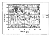
図3はセンサPl_1、Pl_2、Pl_3の異なる伸縮に対するインダクタンス変化を示す。ここで、横方向に切断されたバンドを有するPl_1及びPl_2は一番高い磁気−弾性関係を示すことが明確に示される。これらの2つのサンプルはまた非常に高い導磁率を表示する。このことはガラス破損実験においても、同様な励起状態における信号レベルがPl_1及びPl_2に対して高いことが示される。Pl_2は、Pl_1及びPl_3と比較してかなり広帯域の信号スペクトルを示す。これはおそらく表1に示される、より大きな接着特性により説明される。 FIG. 3 shows the inductance change for different expansion and contraction of the sensors Pl_1, Pl_2 and Pl_3. Here, it is clearly shown that Pl_1 and Pl_2 having bands cut in the transverse direction show the highest magneto-elastic relationship. These two samples also display very high magnetic conductivities. This indicates that the signal level in the same excited state is higher for Pl_1 and Pl_2 in the glass breakage experiment. Pl_2 shows a signal spectrum that is considerably wider than that of Pl_1 and Pl_3. This is probably explained by the greater adhesive properties shown in Table 1.
実静的測定を行う一般加速計の開発した最初の試作品への適用
機能的原理
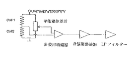
トランスデューサあるいはインジケータは非晶質強磁性体から構成され、これは極めて高い導磁性、5,000<μ<200,000を有すると同時に、ある合金組成に対して比較的高い磁気ひずみ、5<λsat<40ppmを有する特性を所有する。全体としてみると、これは非常に高い磁気弾性関係を備えた材料を提供し、且つそれゆえにセンサ材料として非常に適している。トランスデューサあるいはインジケータは3・16・0.022mmの大きさの2つの非晶質バンドエレメントからできている。このバンドエレメントは図1に示されるように固定ブロックに対して接着される。固定ブロックでは1つのコイルが各バンドエレメントの周囲に巻かれる。この1つ以上のコイルは図2に示されるように半ブリッジで接続される。両バンドエレメントにおける類似の変化が信号を提供しないようにこれらコイルを接続することにより、温度に対する不感受性の高さ及び別の対称崩壊が実現される。2つの非晶質バンドエレメント及び中間プラスチックバンドから構成される「ビーム」を屈曲させると、片方のバンドエレメントの伸長が別のバンドエレメントの圧縮を同時に生じさせる。コイルからの出力信号がその後正反対となり、すなわち伸長におけるインダクタンス(導磁性)の増加及び圧縮における減少を生じる。
Functional principle applied to the first prototype developed by a general accelerometer that performs real static measurements The transducer or indicator is made of amorphous ferromagnet, which has extremely high conductivity, 5,000 <μ <200 Possess properties that have relatively high magnetostriction, 5 <λ sat <40 ppm for certain alloy compositions. Overall, this provides a material with a very high magnetoelastic relationship and is therefore very suitable as a sensor material. The transducer or indicator is made of two amorphous band elements measuring 3.16.0.022 mm. The band element is bonded to the fixed block as shown in FIG. In the fixed block, one coil is wound around each band element . The one or more coils are connected by a half bridge as shown in FIG. By connecting these coils so that similar changes in both band elements do not provide a signal, a high temperature insensitivity and another symmetrical collapse is achieved. When a “beam” composed of two amorphous band elements and an intermediate plastic band is bent, the extension of one band element simultaneously causes the compression of another band element . The output signal from the coil then becomes diametrically opposite, i.e., an increase in inductance (magnetism) in expansion and a decrease in compression.
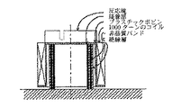
曲げビームの先端部に位置する反応塊(図14)は加速度、ビームの長さ及び質量に比例する曲げモーメントを提供する。このことは当然、ほぼどんな最大加速度に対しても加速計が適応できるようにする。この周波数特性はビーム剛性及び反応塊の質量により実質決定される。 The reaction mass located at the tip of the bending beam (FIG. 14) provides a bending moment proportional to acceleration, beam length and mass. This naturally allows the accelerometer to adapt to almost any maximum acceleration. This frequency characteristic is substantially determined by the beam stiffness and the mass of the reaction mass.
理論
このトランスデューサあるいはインジケータが実静的測定を有するため、測定原理は流量変化により誘発される引張に基づくことがない。本発明では、バンドの相対導磁性は加速計の期待バンド幅よりもおよそ10倍高い周波数を有する搬送波を使用して測定される必要がある。
Theory Since this transducer or indicator has real static measurements, the measurement principle is not based on tension induced by flow rate changes. In the present invention, the relative conductance of the band needs to be measured using a carrier having a frequency approximately 10 times higher than the expected bandwidth of the accelerometer.
直線性の場合には以下の連立方程式がその関数を示す。 In the case of linearity, the following simultaneous equations show the function.
ここでHは磁界であり、Bは電磁流量密度であり、自由空間に対する導磁率μ0=4π・10−7Vs/Amであり、この場合における非晶質バンドへの相対導磁率μである。 Here, H is the magnetic field, B is the electromagnetic flow density, and the magnetic permeability μ 0 = 4π · 10 −7 Vs / Am in this case, which is the relative magnetic permeability μ to the amorphous band in this case. .
更に、σは機械的引張を示し、dは磁気−弾性関係係数を示す。この冒頭のΔは初期値からの変化量を示す。材料パラメータdは、一定の機械的応力、Δσ=0、での最大磁気ひずみを、磁気飽和状態における磁界で割ることにより近似させる。
すなわち、
Further, σ indicates mechanical tension, and d indicates a magneto-elastic relation coefficient. The Δ at the beginning indicates the amount of change from the initial value. The material parameter d is approximated by dividing the maximum magnetostriction at a constant mechanical stress, Δσ = 0, by the magnetic field in the magnetic saturation state.
That is,
従って、 Therefore,
ここで、λmax=35・10−6であり、且つHmax=200A/mから、関係因子d=1.75・10−7m/Aとなり、全ての型の磁気−弾性関係に対して高い値となる。ここで関心となる測定の大きさは伸縮関数としての導磁率である。明確な磁化状態、すなわち一定の公知な磁界が達成されたと仮定すると、上記の方程式の補正を含む電磁流量密度の変化は以下のように表される。 Here, λ max = 35 · 10 −6 and H max = 200 A / m, so that the relational factor d = 1.75 · 10 −7 m / A, and for all types of magneto-elastic relations High value. The magnitude of the measurement of interest here is the magnetic permeability as a stretching function. Assuming that a well-defined magnetization state, i.e. a constant known magnetic field, has been achieved, the change in electromagnetic flow density, including correction of the above equation, is expressed as:
従って、電磁流量密度の変化は、EH=100GPaであり、およそ1.75・104Tである比例定数d・EHと、バンドの伸縮に比例する。 Therefore, the change of the electromagnetic flow density is E H = 100 GPa, and is proportional to the proportionality constant d · E H which is approximately 1.75 · 10 4 T and the expansion and contraction of the band.
コイルが半ブリッジで接続され、片方のバンドが10ppmの伸長を有し且つ他方のバンドが10ppmの圧縮を有すると仮定する。Hフィールドは一定とされ、且つBフィールドの変化は導磁率の変化及び当然コイルのインダクタンスに比例するため、平衡状態のブリッジからの出力信号は以下の式で表される。 Assume that the coils are connected by a half bridge, one band has 10 ppm extension and the other band has 10 ppm compression. Since the H field is constant and the change in the B field is proportional to the change in the magnetic permeability and naturally the inductance of the coil, the output signal from the bridge in the balanced state is expressed by the following equation.
これは、出力信号が非常に強力であるため増幅する必要がない。 This does not need to be amplified because the output signal is very strong.
測定結果
各コイルは800ターンを有し、8,2mHのインダクタンスを提供する。この半ブリッジは4,4V及び19,3kHzの振幅の正弦波電波を提供する。このコイルは直列に接続されているため、ブリッジインピーダンスは10kΩの大きさで維持され、これはオペアンプにより増幅されて良好に適用できることを意味する。
Measurement Results Each coil has 800 turns and provides an inductance of 8,2 mH. This half bridge provides sinusoidal waves with amplitudes of 4, 4 V and 19, 3 kHz. Since this coil is connected in series, the bridge impedance is maintained at a magnitude of 10 kΩ, which means that it is amplified by an operational amplifier and can be applied well.
トランスデューサの較正のために、引力として9.81Gの重力が使用される。これは35mV/Gの感度を提供する。このトランスデューサはおよそ1Vで飽和状態となり、これは直線面積がおよそ±0.5Cでありこれは±14Gに等しいことを示す。共振周波数は以下の式で表される。 Gravity of 9.81 G is used as the attractive force for transducer calibration. This provides a sensitivity of 35 mV / G. The transducer saturates at approximately 1V, which indicates that the linear area is approximately ± 0.5C, which is equal to ± 14G. The resonance frequency is expressed by the following equation.
これはインパルス応答を調べると図3に示すようにおよそ80Hzまで測定された。 This was measured up to approximately 80 Hz as shown in FIG. 3 when examining the impulse response.
加速計試験装置における測定
直線性を調べるために、ある程度の周波数特性まで、加速計試験装置にて測定された。
Measurement with accelerometer test equipment In order to investigate the linearity, some frequency characteristics were measured with the accelerometer test equipment.
図4、5、6及び7に共通する特徴として、ある相対的に大きな出力信号変動曲線が基準加速計からの出力信号を示し、別の同様に大きな出力信号変動曲線が原型加速計からの信号を示し、一方ほぼ実線の連続曲線はまさに正確である解析的模擬加速度を示す。軸の目盛としてy軸においては加速度Gであり、x軸においては時間、秒である。およそ1,5周期が全体を通して存在した。 As a feature common to FIGS. 4, 5, 6, and 7, a relatively large output signal fluctuation curve indicates an output signal from the reference accelerometer, and another similarly large output signal fluctuation curve indicates a signal from the prototype accelerometer. On the other hand, the continuous curve, which is almost a solid line, shows an analytical simulated acceleration that is exactly accurate. The axis scale is acceleration G on the y axis and time and seconds on the x axis. There were approximately 1,5 cycles throughout.
加速計の出力信号を模擬加速度と比較し、相関させることにより、周波数応答が図8で示されるように導かれる。 By comparing and correlating the output signal of the accelerometer with the simulated acceleration, a frequency response is derived as shown in FIG.
開発された加速計が期待直線性限界の14Gまで良好な直線性を示す。周波数が80Hzの共振周波数に接近し始めるまで周波数依存を示すような形状を推測するものは全くない。図8中の11Hzにおける下り勾配は飽和が達成されたことを説明する。 The developed accelerometer shows good linearity up to the expected linearity limit of 14G. There is nothing to infer a shape that shows frequency dependence until the frequency begins to approach the resonant frequency of 80 Hz. The downslope at 11 Hz in FIG. 8 explains that saturation has been achieved.
アコースティックエミッション用センサの開発された最初の試作品への適用
機能的原理
トランスデューサあるいはインジケータは非晶質強磁性体から構成され、これは極めて高い導磁性、5,000<μ<200,000を有すると同時に、ある合金組成に対して比較的高い磁気ひずみ、5<λsat<40ppmを有する特性を所有する。全体としてみると、これは非常に高い磁気−弾性関係を備えた材料を提供し、且つそれゆえにセンサ材料として非常に適している。トランスデューサあるいはインジケータは3・18・0,022mmの大きさの1つの非晶質バンドからできている。このバンドは間に介在する絶縁性プラスチックバンドと共に2ターンして巻かれる。このバンドは次に短絡化二次巻線として機能するため、このバンドの異なる層がたがいに電気接点を有さないことが必須的に重要である。結果としてできた活性シリンダは薄い接着部を有して測定対象物上に接着され更に反対側では半球形のプラスチックボビンの底部まで接着される。プラスチックボビンの底部上に、反応塊が固定され一方1,000ターンのコイルがその側面上を巻かれる。このトランスデューサの原理は唯1つのコイルだけが存在するため動的周期を検知するのに最適である。半ブリッジに接合させた2つのコイルを使用することにより(コイルが異なって操作され、すなわち正の加速度に対して1つのコイルが正の出力信号を提供する一方で別のコイルが相当する負の出力信号を提供すると仮定する)、コイルに対して対称的に生じる外部の、大域現象(熱、磁界など)により生じる変動、全ての電流(空中電磁波など)の影響は減少/除去される利点がある。
Functional principle applied to the first prototype of an acoustic emission sensor developed The transducer or indicator is made of amorphous ferromagnet, which has a very high magnetic conductivity, 5,000 <μ <200,000 At the same time, it possesses properties that have a relatively high magnetostriction, 5 <λ sat <40 ppm, for an alloy composition. Overall, this provides a material with a very high magneto-elastic relationship and is therefore very suitable as a sensor material. The transducer or indicator is made of one amorphous band measuring 3.18.0,022 mm. This band is wound in two turns with an insulating plastic band interposed therebetween. Since this band then functions as a shorted secondary winding, it is essential that the different layers of this band do not have electrical contacts. The resulting active cylinder is glued onto the object to be measured with a thin glue and on the other side to the bottom of the hemispherical plastic bobbin. The reaction mass is fixed on the bottom of the plastic bobbin, while a 1,000 turn coil is wound on its side. The principle of this transducer is optimal for detecting the dynamic period since there is only one coil. By using two coils joined to the half bridge (the coils are operated differently, ie one coil provides a positive output signal for positive acceleration while another coil has a corresponding negative (Assuming to provide an output signal), fluctuations caused by external phenomena that occur symmetrically with respect to the coil (thermal, magnetic field, etc.), and the effects of all currents (such as airborne electromagnetic waves) are reduced / removed. is there.
このプラスチックボビンの底部に固定される反応塊(図14)はその加速度及び質量に比例する活性シリンダの反力を提供する。これは当然加速計をいかなる最大加速度及びどんな共振周波数に対しても適用可能であることを示す。この周波数特性はシリンダの剛性及び同様に反応塊の質量により実質決定される。 The reaction mass (FIG. 14) secured to the bottom of this plastic bobbin provides an active cylinder reaction force proportional to its acceleration and mass. This naturally indicates that the accelerometer can be applied to any maximum acceleration and any resonance frequency. This frequency characteristic is substantially determined by the cylinder stiffness and likewise the mass of the reaction mass.
理論
高い周波数の信号を検知するために、流量変化を検知して、これがバンドに対する変形量に比例することを推定するだけの簡単な利点を有する。このことは、非磁性バンドが伸長変化において流量変化を生じないため、磁気的に明確な初期状態が達成されることを意味する。磁化基礎状態を達成するために、原則的にアース磁界は30−60μT(20−40A/m)で充分であるが、他方では、インジケータが搭載され測定される際にはアース磁界の大きさ及び方向を監視することは非実用的である。
Theory To detect high frequency signals, it has the simple advantage of detecting flow rate changes and estimating that this is proportional to the amount of deformation for the band. This means that a magnetically clear initial state is achieved because the non-magnetic band does not cause a flow rate change in the extension change. In order to achieve the magnetization ground state, in principle, a ground magnetic field of 30-60 μT (20-40 A / m) is sufficient, while on the other hand, when the indicator is mounted and measured, Monitoring direction is impractical.
満足な初期状態を達成するための2つの方法がある。
1.わずかな磁気封入及び巻き上げコイルへの直流。
2.わずかな磁気封入及び永久磁石を備えたバイアス磁化がある。
There are two ways to achieve a satisfactory initial state.
1. Slight magnetic encapsulation and direct current to winding coil.
2. There is a bias magnetization with a slight magnetic encapsulation and a permanent magnet.
磁界の大きさは磁化が0,2−0,7Tとなるようにして、これはバンドにおける磁界が2−56A/mの大きさの程度となることを意味する。磁界の大きさは通常次式から計算される。 The magnitude of the magnetic field is such that the magnetization is 0, 2-0, 7T, which means that the magnetic field in the band is of the order of 2-56 A / m. The magnitude of the magnetic field is usually calculated from the following equation.
ここで、Hは磁界であり、Bは電磁流密度であり、自由空間に対する導磁率μ0=4π・10−7Vs/Amであり、この場合における非晶質バンドへの相対導磁率μである。測定信号は伸長/圧縮に由来するバンドにおける電磁流量変化量を検知することにより得られる。 Here, H is a magnetic field, B is an electromagnetic current density, and a magnetic permeability μ 0 = 4π · 10 −7 Vs / Am, and in this case, a relative magnetic permeability μ to an amorphous band is there. The measurement signal is obtained by detecting the amount of change in electromagnetic flow rate in the band derived from expansion / compression.
直線的な場合に関して、以下の連立方程式がその関数を示す。 For the linear case, the following simultaneous equations show the function:
![]()
![]()
ここで、σは機械的応力を示し、dは磁気−弾性関係係数を示す。この冒頭のΔは初期値からの変化量を示す。材料パラメータdは、一定の機械的応力、Δσ=0、での最大磁気ひずみを、磁気飽和状態における磁界で割ることにより近似させる。すなわち、 Here, σ represents mechanical stress, and d represents a magneto-elastic relationship coefficient. The Δ at the beginning indicates the amount of change from the initial value. The material parameter d is approximated by dividing the maximum magnetostriction at a constant mechanical stress, Δσ = 0, by the magnetic field in the magnetic saturation state. That is,
従って、 Therefore,
ここで、λmax=35・10−6であり、且つHmax=200A/mから、関係因子d=1.75・10−7m/Aとなり、全ての型の磁気弾性関係に対して高い値となる。 Here, λ max = 35 · 10 −6 and H max = 200 A / m, so the relation factor d = 1.75 · 10 −7 m / A, which is high for all types of magnetoelasticity relationships Value.
期待される出力信号は電磁流量変化量及び機械的応力に比例する。 The expected output signal is proportional to the amount of electromagnetic flow change and mechanical stress.
ここで、Nは巻上コイルにおけるターンの回数であり、更にAは非晶質バンドの断面積である。ΔH=0と仮定すると、以下の方程式が当てはまる。 Here, N is the number of turns in the winding coil, and A is the cross-sectional area of the amorphous band. Assuming ΔH = 0, the following equation applies:
ここでEHは一定の磁界における弾性率である。周波数面への変換及び上記方程式の利用率は、次式で与えられる。 Here, E H is an elastic modulus in a constant magnetic field. The conversion to the frequency plane and the utilization factor of the above equation are given by:
ここでωはrows/secの角周波数である。この曲折アクセントは、振幅値が与えられることを示す。 Here, ω is an angular frequency of rows / sec. This circumflex accent indicates that an amplitude value is given.
測定結果
650ターンを有するコイルは、3.2mHのインダクタンスを提供する。この共鳴周波数は以下の式で計算される。
Measurement Results A coil with 650 turns provides an inductance of 3.2 mH. This resonance frequency is calculated by the following equation.
ここで、弾性率が100GPaであり、活性シリンダの高さが3mmであり、断面積が2・3・π・0,022mm2であり、反応塊が4グラムであると仮定すると、共鳴周波数はおよそ10kHzである。図2は大きな鉄ブランク上に搭載し、更にハンマーの打撃により励起させた際に、トランスデューサからの50倍増幅させた出力信号を示す。 Here, assuming that the elastic modulus is 100 GPa, the height of the active cylinder is 3 mm, the cross-sectional area is 2 · 3 · π · 0,022 mm 2 , and the reaction mass is 4 grams, the resonance frequency is About 10 kHz. FIG. 2 shows the output signal amplified by 50 times from the transducer when mounted on a large iron blank and further excited by hammering.
図15において時系列での周波数解析が示され約5kHzまで上昇する信号が広帯域で生じその後8kHzと60kHzの別個のピークを有する。8kHzの信号はトランスデューサ共振であり、一方60kHz信号は従来からアコースティックエミッションと呼ばれる、例えば材料変形エネルギーの過渡的開放であることが明らかである。5kHz以下の広帯域信号分は試験体における振動から構成される。 In FIG. 15, a time series frequency analysis is shown and a signal rising to about 5 kHz occurs in a wide band and then has separate peaks at 8 kHz and 60 kHz. It is clear that the 8 kHz signal is transducer resonance, while the 60 kHz signal is traditionally called acoustic emission, for example, a transient release of material deformation energy. The broadband signal component of 5 kHz or less is composed of vibrations in the specimen.
Claims (16)
a.1つ以上のバンド成形エレメントは前記該当箇所に対して自由に懸架される方法で接着され、
b.前記バンドエレメントは非晶性および/またはナノ結晶材料から形成され、
c.前記バンド成形エレメントはピックアップコイルを通して直流を印加するおよび/または永久磁石を利用するバイアス磁化により影響され、
d.前記偏差は前記バンドエレメント内に内部原子運動(振動)を発生して前記バンドエレメントに伝達され、
e.前記偏差により前記原子運動に比例する前記コイル内の検出可能な電磁流量変化(dB/dt)を表示および感知するかあるいは前記コイル内の検出可能なインダクタンス変化を表示および感知し、
f.2つの非晶質バンドエレメント及び中間プラスチックバンドから構成される「ビーム」を屈曲させると、片方のバンドエレメントの伸長が別のバンドエレメントの圧縮を同時に生じさせ、その後、コイルからの出力信号が正反対となり、すなわち伸長におけるインダクタンス(導磁性)の増加及び圧縮における減少を生じ、これにより曲げビームの先端部に位置する反応塊は加速度、ビームの長さ及び質量に比例する曲げモーメントを提供することを特徴とする方法。By detecting based on temporary internal material vibrations, so-called real-time acoustic emission, the deviation occurring in the corresponding location corresponding to the permanent state is displayed and sensed, the deviation dependent element is at least by one or more multi-turn coils In a partially wound method of displaying and sensing deviations,
a. One or more band-forming elements are bonded in such a way as to be freely suspended with respect to the relevant part,
b. The band element is formed from an amorphous and / or nanocrystalline material;
c. The band forming element is influenced by bias magnetization applying a direct current through a pickup coil and / or utilizing a permanent magnet;
d. The deviation is transmitted to the band element by generating internal atomic motion (vibration) in the band element,
e. Displaying and sensing a detectable electromagnetic flow change (dB / dt) in the coil proportional to the atomic motion by the deviation or displaying and sensing a detectable inductance change in the coil ;
f. When a “beam” composed of two amorphous band elements and an intermediate plastic band is bent, the extension of one band element causes the compression of another band element at the same time, and then the output signal from the coil is exactly opposite I.e., an increase in inductance (magnetism) in elongation and a decrease in compression, so that the reaction mass located at the tip of the bending beam provides a bending moment proportional to acceleration, beam length and mass. Feature method.
a.1つ以上のバンド成形エレメントは前記該当箇所に対して自由に懸架される方法で接着され、
b.前記バンドエレメントは非晶性あるいはナノ結晶材料から形成され、
c.前記バンド成形エレメントはピックアップコイルを通して直流を印加するおよび/または永久磁石を利用するバイアス磁化により影響され、
d.前記偏差は前記バンドエレメント内に内部原子運動(振動)を発生して前記バンドエレメントに伝達され、
e.前記偏差により前記原子運動に比例する前記コイル内の検出可能な電磁流量変化(dB/dt)を表示および感知するかあるいは前記コイル内の検出可能なインダクタンス変化を表示および感知し、
f.2つの非晶質バンドエレメント及び中間プラスチックバンドから構成される「ビーム」を屈曲させると、片方のバンドエレメントの伸長が別のバンドエレメントの圧縮を同時に生じさせ、その後、コイルからの出力信号が正反対となり、すなわち伸長におけるインダクタンス(導磁性)の増加及び圧縮における減少を生じ、これにより曲げビームの先端部に位置する反応塊は加速度、ビームの長さ及び質量に比例する曲げモーメントを提供することを特徴とする装置。By detecting based on temporary internal material vibrations, so-called real-time acoustic emission, the deviation occurring in the corresponding location corresponding to the permanent state is displayed and sensed, the deviation dependent element is at least by one or more multi-turn coils In a rolled up device for displaying and sensing deviations,
a. One or more band-forming elements are bonded in such a way as to be freely suspended with respect to the relevant part,
b. The band element is formed from an amorphous or nanocrystalline material,
c. The band forming element is influenced by bias magnetization applying a direct current through a pickup coil and / or utilizing a permanent magnet;
d. The deviation is transmitted to the band element by generating internal atomic motion (vibration) in the band element,
e. Displaying and sensing a detectable electromagnetic flow change (dB / dt) in the coil proportional to the atomic motion by the deviation or displaying and sensing a detectable inductance change in the coil ;
f. When a “beam” composed of two amorphous band elements and an intermediate plastic band is bent, the extension of one band element causes the compression of another band element at the same time, and then the output signal from the coil is exactly opposite I.e., an increase in inductance (magnetism) in elongation and a decrease in compression, so that the reaction mass located at the tip of the bending beam provides a bending moment proportional to acceleration, beam length and mass. Features device.
Applications Claiming Priority (2)
| Application Number | Priority Date | Filing Date | Title |
|---|---|---|---|
| SE0201927A SE523321C2 (en) | 2002-06-20 | 2002-06-20 | Method and apparatus for sensing and indicating acoustic emission |
| PCT/SE2003/000871 WO2004001353A1 (en) | 2002-06-20 | 2003-05-28 | Sensor |
Publications (3)
| Publication Number | Publication Date |
|---|---|
| JP2005530173A JP2005530173A (en) | 2005-10-06 |
| JP2005530173A5 JP2005530173A5 (en) | 2006-10-26 |
| JP4233523B2 true JP4233523B2 (en) | 2009-03-04 |
Family
ID=20288285
Family Applications (1)
| Application Number | Title | Priority Date | Filing Date |
|---|---|---|---|
| JP2004515286A Expired - Lifetime JP4233523B2 (en) | 2002-06-20 | 2003-05-28 | Method and apparatus for sensing permanent state deviation |
Country Status (14)
| Country | Link |
|---|---|
| US (1) | US7282822B2 (en) |
| EP (1) | EP1514082A1 (en) |
| JP (1) | JP4233523B2 (en) |
| KR (1) | KR101046539B1 (en) |
| CN (1) | CN100489471C (en) |
| BR (1) | BR0312434A (en) |
| CA (1) | CA2489171C (en) |
| EA (1) | EA009475B1 (en) |
| IL (1) | IL165774A0 (en) |
| MX (1) | MXPA04012921A (en) |
| NO (1) | NO329969B1 (en) |
| SE (1) | SE523321C2 (en) |
| WO (1) | WO2004001353A1 (en) |
| ZA (1) | ZA200409956B (en) |
Families Citing this family (7)
| Publication number | Priority date | Publication date | Assignee | Title |
|---|---|---|---|---|
| CA2517388A1 (en) * | 2003-03-03 | 2004-09-16 | Adaptive Materials Technology Oy | A damping and actuating apparatus comprising magnetostrictive material, a vibration dampening device and use of said apparatus |
| KR101592950B1 (en) * | 2009-02-27 | 2016-02-11 | 연세대학교 산학협력단 | Paint for measuring deformation of structure having the magnetic material tape comprising the same and deformation rate measuring method of structure using the same |
| CN101650217B (en) * | 2009-09-23 | 2011-02-02 | 上海交通大学 | Non-contact coaxial magnetoelastic sensor |
| CN104316225B (en) * | 2014-11-07 | 2016-04-20 | 山东科技大学 | A kind of magnetic rheology elastic body pressure transducer |
| ITUA20162508A1 (en) * | 2016-04-12 | 2017-10-12 | Safecertifiedstructure Ingegneria S R L | Survey method and device for measuring stresses in an agglomerate structure |
| CN107063073B (en) * | 2017-04-12 | 2020-03-20 | 爱德森(厦门)电子有限公司 | Object deformation electromagnetic monitoring device and method |
| CN109900793B (en) * | 2019-04-16 | 2021-04-27 | 中国特种设备检测研究院 | Magnetic acoustic emission detection method for creep damage of ferromagnetic metal component |
Family Cites Families (16)
| Publication number | Priority date | Publication date | Assignee | Title |
|---|---|---|---|---|
| US4463610A (en) * | 1982-02-18 | 1984-08-07 | Allied Corporation | Tuned vibration detector |
| JPH01189971A (en) * | 1988-01-26 | 1989-07-31 | Toshiba Corp | Toque sensor |
| JP2800347B2 (en) * | 1990-02-07 | 1998-09-21 | 株式会社豊田自動織機製作所 | Magnetostrictive torque sensor |
| DE4008644C1 (en) * | 1990-03-17 | 1991-05-29 | Mercedes-Benz Aktiengesellschaft, 7000 Stuttgart, De | |
| JPH0442004A (en) * | 1990-06-07 | 1992-02-12 | Toshiba Corp | Strain sensor and manufacture thereof |
| DE4309413C2 (en) * | 1993-03-19 | 1996-03-07 | Holger Kabelitz | Magnetoelastic strain measuring unit for the detection of strains on a component surface |
| JP3541996B2 (en) * | 1995-09-26 | 2004-07-14 | Tdk株式会社 | Magnetostrictive device |
| GB9806994D0 (en) * | 1998-04-02 | 1998-06-03 | New Transducers Ltd | Acoustic device |
| GB9818959D0 (en) * | 1998-09-02 | 1998-10-21 | New Transducers Ltd | Panelform loudspeaker |
| DE19653428C1 (en) * | 1996-12-20 | 1998-03-26 | Vacuumschmelze Gmbh | Producing amorphous ferromagnetic cobalt alloy strip for wound cores |
| US6018296A (en) * | 1997-07-09 | 2000-01-25 | Vacuumschmelze Gmbh | Amorphous magnetostrictive alloy with low cobalt content and method for annealing same |
| JPH11194158A (en) * | 1998-01-05 | 1999-07-21 | Alps Electric Co Ltd | Azimuth sensor |
| US6542342B1 (en) * | 1998-11-30 | 2003-04-01 | Nec Corporation | Magnetoresistive effect transducer having longitudinal bias layer directly connected to free layer |
| JP3643823B2 (en) * | 2002-09-30 | 2005-04-27 | 株式会社東芝 | Magnetoresistive effect element |
| JP3835447B2 (en) * | 2002-10-23 | 2006-10-18 | ヤマハ株式会社 | Magnetic sensor, method for manufacturing the same, and magnet array suitable for the method |
| JP2006245275A (en) * | 2005-03-03 | 2006-09-14 | Alps Electric Co Ltd | Magnetic sensing element |
-
2002
- 2002-06-20 SE SE0201927A patent/SE523321C2/en not_active IP Right Cessation
-
2003
- 2003-05-28 JP JP2004515286A patent/JP4233523B2/en not_active Expired - Lifetime
- 2003-05-28 EA EA200401567A patent/EA009475B1/en not_active IP Right Cessation
- 2003-05-28 EP EP03733699A patent/EP1514082A1/en not_active Ceased
- 2003-05-28 CA CA2489171A patent/CA2489171C/en not_active Expired - Fee Related
- 2003-05-28 MX MXPA04012921A patent/MXPA04012921A/en unknown
- 2003-05-28 BR BR0312434-7A patent/BR0312434A/en not_active IP Right Cessation
- 2003-05-28 KR KR1020047020796A patent/KR101046539B1/en active IP Right Grant
- 2003-05-28 US US10/518,126 patent/US7282822B2/en not_active Expired - Lifetime
- 2003-05-28 CN CNB038143925A patent/CN100489471C/en not_active Expired - Fee Related
- 2003-05-28 WO PCT/SE2003/000871 patent/WO2004001353A1/en active Application Filing
-
2004
- 2004-12-07 NO NO20045350A patent/NO329969B1/en not_active IP Right Cessation
- 2004-12-08 ZA ZA200409956A patent/ZA200409956B/en unknown
- 2004-12-14 IL IL16577404A patent/IL165774A0/en unknown
Also Published As
| Publication number | Publication date |
|---|---|
| NO20045350L (en) | 2005-02-04 |
| CN100489471C (en) | 2009-05-20 |
| EA200401567A1 (en) | 2005-08-25 |
| SE0201927L (en) | 2003-12-21 |
| BR0312434A (en) | 2005-04-19 |
| CA2489171C (en) | 2011-12-13 |
| CN1662795A (en) | 2005-08-31 |
| WO2004001353A1 (en) | 2003-12-31 |
| NO329969B1 (en) | 2011-01-31 |
| KR101046539B1 (en) | 2011-07-06 |
| SE523321C2 (en) | 2004-04-13 |
| NO20045350D0 (en) | 2004-12-07 |
| IL165774A0 (en) | 2006-01-15 |
| EP1514082A1 (en) | 2005-03-16 |
| JP2005530173A (en) | 2005-10-06 |
| ZA200409956B (en) | 2006-07-26 |
| US7282822B2 (en) | 2007-10-16 |
| EA009475B1 (en) | 2008-02-28 |
| AU2003238987A1 (en) | 2004-01-06 |
| US20050242806A1 (en) | 2005-11-03 |
| SE0201927D0 (en) | 2002-06-20 |
| MXPA04012921A (en) | 2005-07-26 |
| KR20050016602A (en) | 2005-02-21 |
| CA2489171A1 (en) | 2003-12-31 |
Similar Documents
| Publication | Publication Date | Title |
|---|---|---|
| US7454978B2 (en) | Versatile strain sensor employing magnetostrictive electrical conductors | |
| Schmidt et al. | Characterization of nano-dimensional thin-film elastic moduli using magnetoelastic sensors | |
| US4314202A (en) | Flexural vibration sensor with magnetic field generating and sensing | |
| US7215118B2 (en) | Transducer for generating and measuring torsional waves, and apparatus and method for structural diagnosis using the same | |
| KR930701723A (en) | Strain monitoring device and method for use in stressed mechanical structures | |
| US20070113684A1 (en) | Apparatus and method for generating and sensing torsional vibrations using magnetostriction | |
| Bian et al. | A resonant magnetic field sensor with high quality factor based on quartz crystal resonator and magnetostrictive stress coupling | |
| CN110567573A (en) | Method for outputting measured exciting force signal of piezoelectric vibration sensor with high sensitivity | |
| WO2007116218A1 (en) | Measuring physical quantities | |
| Pepakayala et al. | Passive wireless strain sensors using microfabricated magnetoelastic beam elements | |
| Knapp et al. | Measurement of shock events by means of strain gauges and accelerometers | |
| JP4233523B2 (en) | Method and apparatus for sensing permanent state deviation | |
| US9726557B2 (en) | Magnetoelastic strain sensor | |
| Wang et al. | A highly sensitive magnetometer based on the Villari effect | |
| Hlenschi et al. | Flexible force sensors based on permeability change in ultra-soft amorphous wires | |
| AU2003238987B2 (en) | Sensor | |
| Muro et al. | Magnetostrictive-ring type torque sensor using two Hall ICs with differential magnetic field detection | |
| Hortschitz et al. | Novel MOEMS Lorentz force transducer for magnetic fields | |
| Ong et al. | Magnetically soft higher order harmonic stress and temperature sensors | |
| EP1301766A1 (en) | Pressure transducer | |
| Yamazaki et al. | Novel dynamic force sensing system using magnetostrictive energy harvester | |
| Pereles et al. | A wireless, magnetoelastic-based sensor array for force monitoring on a hard surface | |
| Oppermann et al. | A8. 3-A Novel Magneto–Elastic Force Sensor Design Based On Terfenol–D | |
| Ezzouine et al. | Conception And Realisation of a Sensor Electromagnetic Force-Displacement | |
| US4471303A (en) | Flexural vibration transducer with magnetic field generating |
Legal Events
| Date | Code | Title | Description |
|---|---|---|---|
| A621 | Written request for application examination |
Free format text: JAPANESE INTERMEDIATE CODE: A621 Effective date: 20060511 |
|
| A521 | Request for written amendment filed |
Free format text: JAPANESE INTERMEDIATE CODE: A523 Effective date: 20060905 |
|
| A977 | Report on retrieval |
Free format text: JAPANESE INTERMEDIATE CODE: A971007 Effective date: 20080418 |
|
| A131 | Notification of reasons for refusal |
Free format text: JAPANESE INTERMEDIATE CODE: A131 Effective date: 20080423 |
|
| A601 | Written request for extension of time |
Free format text: JAPANESE INTERMEDIATE CODE: A601 Effective date: 20080722 |
|
| A602 | Written permission of extension of time |
Free format text: JAPANESE INTERMEDIATE CODE: A602 Effective date: 20080729 |
|
| A601 | Written request for extension of time |
Free format text: JAPANESE INTERMEDIATE CODE: A601 Effective date: 20080820 |
|
| A602 | Written permission of extension of time |
Free format text: JAPANESE INTERMEDIATE CODE: A602 Effective date: 20080827 |
|
| A521 | Request for written amendment filed |
Free format text: JAPANESE INTERMEDIATE CODE: A523 Effective date: 20081023 |
|
| TRDD | Decision of grant or rejection written | ||
| A01 | Written decision to grant a patent or to grant a registration (utility model) |
Free format text: JAPANESE INTERMEDIATE CODE: A01 Effective date: 20081119 |
|
| A01 | Written decision to grant a patent or to grant a registration (utility model) |
Free format text: JAPANESE INTERMEDIATE CODE: A01 |
|
| A61 | First payment of annual fees (during grant procedure) |
Free format text: JAPANESE INTERMEDIATE CODE: A61 Effective date: 20081209 |
|
| FPAY | Renewal fee payment (event date is renewal date of database) |
Free format text: PAYMENT UNTIL: 20111219 Year of fee payment: 3 |
|
| R150 | Certificate of patent or registration of utility model |
Ref document number: 4233523 Country of ref document: JP Free format text: JAPANESE INTERMEDIATE CODE: R150 Free format text: JAPANESE INTERMEDIATE CODE: R150 |
|
| FPAY | Renewal fee payment (event date is renewal date of database) |
Free format text: PAYMENT UNTIL: 20121219 Year of fee payment: 4 |
|
| R250 | Receipt of annual fees |
Free format text: JAPANESE INTERMEDIATE CODE: R250 |
|
| R250 | Receipt of annual fees |
Free format text: JAPANESE INTERMEDIATE CODE: R250 |
|
| R250 | Receipt of annual fees |
Free format text: JAPANESE INTERMEDIATE CODE: R250 |
|
| R250 | Receipt of annual fees |
Free format text: JAPANESE INTERMEDIATE CODE: R250 |
|
| R250 | Receipt of annual fees |
Free format text: JAPANESE INTERMEDIATE CODE: R250 |
|
| R250 | Receipt of annual fees |
Free format text: JAPANESE INTERMEDIATE CODE: R250 |
|
| R250 | Receipt of annual fees |
Free format text: JAPANESE INTERMEDIATE CODE: R250 |
|
| R250 | Receipt of annual fees |
Free format text: JAPANESE INTERMEDIATE CODE: R250 |
|
| R250 | Receipt of annual fees |
Free format text: JAPANESE INTERMEDIATE CODE: R250 |
|
| R250 | Receipt of annual fees |
Free format text: JAPANESE INTERMEDIATE CODE: R250 |
|
| R250 | Receipt of annual fees |
Free format text: JAPANESE INTERMEDIATE CODE: R250 |
|
| R250 | Receipt of annual fees |
Free format text: JAPANESE INTERMEDIATE CODE: R250 |
|
| EXPY | Cancellation because of completion of term |