JP4232209B2 - Compressed image data editing apparatus and compressed image data editing method - Google Patents
Compressed image data editing apparatus and compressed image data editing method Download PDFInfo
- Publication number
- JP4232209B2 JP4232209B2 JP00803298A JP803298A JP4232209B2 JP 4232209 B2 JP4232209 B2 JP 4232209B2 JP 00803298 A JP00803298 A JP 00803298A JP 803298 A JP803298 A JP 803298A JP 4232209 B2 JP4232209 B2 JP 4232209B2
- Authority
- JP
- Japan
- Prior art keywords
- vbv
- picture
- stream
- elementary stream
- delay
- Prior art date
- Legal status (The legal status is an assumption and is not a legal conclusion. Google has not performed a legal analysis and makes no representation as to the accuracy of the status listed.)
- Expired - Fee Related
Links
Images


Classifications
-
- H—ELECTRICITY
- H04—ELECTRIC COMMUNICATION TECHNIQUE
- H04N—PICTORIAL COMMUNICATION, e.g. TELEVISION
- H04N21/00—Selective content distribution, e.g. interactive television or video on demand [VOD]
- H04N21/20—Servers specifically adapted for the distribution of content, e.g. VOD servers; Operations thereof
- H04N21/23—Processing of content or additional data; Elementary server operations; Server middleware
- H04N21/236—Assembling of a multiplex stream, e.g. transport stream, by combining a video stream with other content or additional data, e.g. inserting a URL [Uniform Resource Locator] into a video stream, multiplexing software data into a video stream; Remultiplexing of multiplex streams; Insertion of stuffing bits into the multiplex stream, e.g. to obtain a constant bit-rate; Assembling of a packetised elementary stream
-
- H—ELECTRICITY
- H04—ELECTRIC COMMUNICATION TECHNIQUE
- H04N—PICTORIAL COMMUNICATION, e.g. TELEVISION
- H04N21/00—Selective content distribution, e.g. interactive television or video on demand [VOD]
- H04N21/20—Servers specifically adapted for the distribution of content, e.g. VOD servers; Operations thereof
- H04N21/23—Processing of content or additional data; Elementary server operations; Server middleware
- H04N21/234—Processing of video elementary streams, e.g. splicing of video streams, manipulating MPEG-4 scene graphs
- H04N21/23406—Processing of video elementary streams, e.g. splicing of video streams, manipulating MPEG-4 scene graphs involving management of server-side video buffer
-
- G—PHYSICS
- G11—INFORMATION STORAGE
- G11B—INFORMATION STORAGE BASED ON RELATIVE MOVEMENT BETWEEN RECORD CARRIER AND TRANSDUCER
- G11B27/00—Editing; Indexing; Addressing; Timing or synchronising; Monitoring; Measuring tape travel
- G11B27/02—Editing, e.g. varying the order of information signals recorded on, or reproduced from, record carriers
- G11B27/031—Electronic editing of digitised analogue information signals, e.g. audio or video signals
- G11B27/036—Insert-editing
-
- H—ELECTRICITY
- H04—ELECTRIC COMMUNICATION TECHNIQUE
- H04N—PICTORIAL COMMUNICATION, e.g. TELEVISION
- H04N21/00—Selective content distribution, e.g. interactive television or video on demand [VOD]
- H04N21/20—Servers specifically adapted for the distribution of content, e.g. VOD servers; Operations thereof
- H04N21/23—Processing of content or additional data; Elementary server operations; Server middleware
- H04N21/234—Processing of video elementary streams, e.g. splicing of video streams, manipulating MPEG-4 scene graphs
- H04N21/23424—Processing of video elementary streams, e.g. splicing of video streams, manipulating MPEG-4 scene graphs involving splicing one content stream with another content stream, e.g. for inserting or substituting an advertisement
-
- H—ELECTRICITY
- H04—ELECTRIC COMMUNICATION TECHNIQUE
- H04N—PICTORIAL COMMUNICATION, e.g. TELEVISION
- H04N21/00—Selective content distribution, e.g. interactive television or video on demand [VOD]
- H04N21/20—Servers specifically adapted for the distribution of content, e.g. VOD servers; Operations thereof
- H04N21/23—Processing of content or additional data; Elementary server operations; Server middleware
- H04N21/236—Assembling of a multiplex stream, e.g. transport stream, by combining a video stream with other content or additional data, e.g. inserting a URL [Uniform Resource Locator] into a video stream, multiplexing software data into a video stream; Remultiplexing of multiplex streams; Insertion of stuffing bits into the multiplex stream, e.g. to obtain a constant bit-rate; Assembling of a packetised elementary stream
- H04N21/23611—Insertion of stuffing data into a multiplex stream, e.g. to obtain a constant bitrate
-
- H—ELECTRICITY
- H04—ELECTRIC COMMUNICATION TECHNIQUE
- H04N—PICTORIAL COMMUNICATION, e.g. TELEVISION
- H04N21/00—Selective content distribution, e.g. interactive television or video on demand [VOD]
- H04N21/40—Client devices specifically adapted for the reception of or interaction with content, e.g. set-top-box [STB]; Operations thereof
- H04N21/43—Processing of content or additional data, e.g. demultiplexing additional data from a digital video stream; Elementary client operations, e.g. monitoring of home network or synchronising decoder's clock; Client middleware
- H04N21/44—Processing of video elementary streams, e.g. splicing a video clip retrieved from local storage with an incoming video stream, rendering scenes according to MPEG-4 scene graphs
- H04N21/44004—Processing of video elementary streams, e.g. splicing a video clip retrieved from local storage with an incoming video stream, rendering scenes according to MPEG-4 scene graphs involving video buffer management, e.g. video decoder buffer or video display buffer
-
- H—ELECTRICITY
- H04—ELECTRIC COMMUNICATION TECHNIQUE
- H04N—PICTORIAL COMMUNICATION, e.g. TELEVISION
- H04N21/00—Selective content distribution, e.g. interactive television or video on demand [VOD]
- H04N21/40—Client devices specifically adapted for the reception of or interaction with content, e.g. set-top-box [STB]; Operations thereof
- H04N21/43—Processing of content or additional data, e.g. demultiplexing additional data from a digital video stream; Elementary client operations, e.g. monitoring of home network or synchronising decoder's clock; Client middleware
- H04N21/44—Processing of video elementary streams, e.g. splicing a video clip retrieved from local storage with an incoming video stream, rendering scenes according to MPEG-4 scene graphs
- H04N21/44016—Processing of video elementary streams, e.g. splicing a video clip retrieved from local storage with an incoming video stream, rendering scenes according to MPEG-4 scene graphs involving splicing one content stream with another content stream, e.g. for substituting a video clip
-
- H—ELECTRICITY
- H04—ELECTRIC COMMUNICATION TECHNIQUE
- H04N—PICTORIAL COMMUNICATION, e.g. TELEVISION
- H04N21/00—Selective content distribution, e.g. interactive television or video on demand [VOD]
- H04N21/80—Generation or processing of content or additional data by content creator independently of the distribution process; Content per se
- H04N21/81—Monomedia components thereof
- H04N21/812—Monomedia components thereof involving advertisement data
-
- G—PHYSICS
- G11—INFORMATION STORAGE
- G11B—INFORMATION STORAGE BASED ON RELATIVE MOVEMENT BETWEEN RECORD CARRIER AND TRANSDUCER
- G11B2220/00—Record carriers by type
- G11B2220/20—Disc-shaped record carriers
-
- G—PHYSICS
- G11—INFORMATION STORAGE
- G11B—INFORMATION STORAGE BASED ON RELATIVE MOVEMENT BETWEEN RECORD CARRIER AND TRANSDUCER
- G11B2220/00—Record carriers by type
- G11B2220/90—Tape-like record carriers
-
- G—PHYSICS
- G11—INFORMATION STORAGE
- G11B—INFORMATION STORAGE BASED ON RELATIVE MOVEMENT BETWEEN RECORD CARRIER AND TRANSDUCER
- G11B27/00—Editing; Indexing; Addressing; Timing or synchronising; Monitoring; Measuring tape travel
- G11B27/02—Editing, e.g. varying the order of information signals recorded on, or reproduced from, record carriers
- G11B27/031—Electronic editing of digitised analogue information signals, e.g. audio or video signals
- G11B27/032—Electronic editing of digitised analogue information signals, e.g. audio or video signals on tapes
-
- G—PHYSICS
- G11—INFORMATION STORAGE
- G11B—INFORMATION STORAGE BASED ON RELATIVE MOVEMENT BETWEEN RECORD CARRIER AND TRANSDUCER
- G11B27/00—Editing; Indexing; Addressing; Timing or synchronising; Monitoring; Measuring tape travel
- G11B27/02—Editing, e.g. varying the order of information signals recorded on, or reproduced from, record carriers
- G11B27/031—Electronic editing of digitised analogue information signals, e.g. audio or video signals
- G11B27/034—Electronic editing of digitised analogue information signals, e.g. audio or video signals on discs
Description
【0001】
【発明の属する技術分野】
本発明は、テレビジョン会議システム、テレビジョン電話システム、デジタル放送システム等に用いられる圧縮画像データの編集装置及び圧縮画像データの編集方法に関し、特に、2つの圧縮画像データのデータストリームを任意の接続点で接続して、連続した1つの圧縮画像のデータストリームを生成する圧縮画像データの編集装置及び圧縮画像データの編集方法に関するものである。
【0002】
【従来の技術】
近年、デジタル放送システムやテレビジョン電話システム等のデジタル方式による動画像の伝送システムの開発が進んでいる。このようなデジタル方式による動画像の伝送システムでは、一般に、MPEG2ビデオ方式等で画像圧縮した動画像データが取り扱われている。
【0003】
このMPEGとは、ISO/IEC JTC1/SC29(International Organization for Standardization/International Electrotechnical Commission, Joint Technical Committee 1/Sub Committee 29:国際標準化機構/国際電気標準会議 合同技術委員会1/専門部会29)の蓄積用動画像符号化の検討組織の略称であり、MPEG1標準としてISO11172が、MPEG2標準としてISO13818が規格化されている。また、これらの国際標準おいて、システム多重化の項目でISO11172−1及びISO13818−1が、映像符号化の項目でISO11172−2及びISO13818−2が、音声符号化の項目でISO11172−3及びISO13818−3が、それぞれ標準化されている。
【0004】
ここで、MPEG2ビデオ(ISO13818−2)の規格では、入力された圧縮画像データをデコード処理する場合に復号器の前段に設けられた入力バッファがアンダーフロー又はオーバーフローしないように、エンコード処理を行う際に復号器の前段に設けられる入力バッファの容量を予め仮想的に想定し、この入力バッファが破綻しないように発生する符号量を制御することが規定されている。このMPEG2ビデオの規格では、このような発生する符号量の制御用の仮想バッファをVBV(Video Buffering Verifier)バッファと規定し、また、このVBVバッファの容量をVBVバッファサイズ(vbv_buffer_size)として規定している。
【0005】
具体的に、このVBVバッファの機能について、図14を用いて説明する。なお、この図14は、復号器の前段に設けられる入力バッファにMPEGストリームが供給された場合の、この入力バッファに格納されるデータ量の推移を表している。この図14の横軸は、時間を示しており、供給されるMPEGストリームに含まれる各ピクチャのデコードのタイミング(t101,t102,t103・・・)を記入している。また、縦軸は、入力バッファが格納するデータ量(ビット占有量)を示している。
【0006】
入力バッファは、MPEG2ビデオ方式で画像圧縮されたMPEGストリームをそのビットレートに応じて順次格納していく。
【0007】
まず、供給が開始した時刻t100からvbv_delay時間経過した時刻t101において、デコード処理のために、最初のピクチャが復号器により引き抜かれる。
【0008】
ここで、このvbv_delayは、ランダムアクセスにより所定のピクチャデータを取得してそのピクチャのデコード処理をする場合での、入力バッファに格納されるデータ量が初期状態となるまでの時間を示している。このvbv_delayを示すデータは、MPEGストリームのピクチャ層に格納されており、例えば、その時間が90kHzのクロックを用いて表されている。
【0009】
また、復号器により引き抜かれるピクチャのデータ量は、そのピクチャのデータサイズ(picture_size)と、ピクチャスタートコードのデータサイズ(picture_start_code)と、シーケンスヘッダのデータサイズ(sequence_header)とを加えた量である。なお、picture_sizeと、picture_start_codeと、sequence_headerとを加えたデータ量を、以下イメージサイズ(image_size)とする。
【0010】
続いて、この時刻t101以降も、この入力バッファには、MPEGストリームが所定のビットレートに応じて順次供給され続ける。そして、この時刻t101から、デコード管理時間(Decode Time Stamp)の間隔であるΔDTS毎に経過していく各時刻t102,時刻t103・・・時刻n,時刻n+1・・・においても、各ピクチャのイメージサイズ分のデータが復号器により引き抜かれていく。
【0011】
このように、復号器の前段に設けられた入力バッファでは、MPEGストリームがそのビットレートに応じて順次格納されていくとともに、各ピクチャのデコードタイミング(時刻t101,時刻t102,時刻t103・・・)において、そのピクチャのイメージサイズ分のデータが復号器により引き抜かれていくこととなる。
【0012】
ここで、供給されたMPEGストリームの総データ量と各デコードタイミングで引き抜かれたピクチャのイメージサイズの総データ量との差が、この入力バッファのバッファサイズより大きくなると、この入力バッファがオーバフローしてしまう。また、反対に、各デコードタイミングで引き抜かれるピクチャのイメージサイズの総データ量が供給されたMPEGストリームの総データ量よりも大きくなると、この入力バッファがアンダーフローしてしまう。
【0013】
そこで、MPEG2ビデオ(ISO13818−2)の規格では、MPEGストリームのエンコード処理を行う際に、復号器の前段に設けられる入力バッファの容量をVBVバッファサイズ(vbv_buffer_size)として仮想的に想定し、このVBVバッファサイズに対して破綻が生じないように、発生する符号量を制御することが規定されている。
【0014】
【発明が解決しようとする課題】
ところで、MPEG2方式で画像圧縮した動画像を放送する放送局等では、一般に、2つ以上の動画像データをつなぎ合わせて1つの動画像データにする編集処理が行われる。例えば、放送局等では、図15に示すように、映画の動画像データに対して、短時間のコマーシャル等を挿入するといった編集処理が行われている。
【0015】
特に、このような編集処理を行う場合には、伝送のリアルタイム性や処理の簡便性の観点から、ベースバンドの動画像データを取り扱って編集処理を行うのではなく、MPEGストリームをデコードすることなく圧縮画像をそのまま取り扱った編集処理が、従来より行われている。
【0016】
以下、MPEG2ビデオ方式で画像圧縮された第1の圧縮画像データのデータストリーム(以下、メインストリームと呼ぶ。)に対して、MPEG2ビデオ方式で画像圧縮された第2の圧縮画像データのデータストリーム(以下、サブストリームと呼ぶ。)をつなぎ合わせ、1つのスプライスドストリームを生成する従来の第1〜第3の編集処理について説明する。
【0017】
なお、この従来の第1〜第3の編集処理を説明するために用いる図16〜図18には、それぞれ、メインストリームのVBVバッファに対するビット占有量、サブストリームのVBVバッファに対するビット占有量、スプライスドストリームのVBVバッファに対するビット占有量を示すものとする。
【0018】
まず、従来の第1の編集処理について図16を用いて説明する。従来の第1の編集処理では、図16(a)に示すように、メインストリームのつなぎ合わせを行う接続点(Splice Point)を、VBVバッファへの供給の終了のタイミング(時刻t111)としている。また、従来の第1の編集処理では、図16(b)に示すように、サブストリームの接続点(Splice Point)を、VBVバッファへの供給の開始のタイミング(時刻t121)としている。そして、第1の編集処理では、メインストリームとサブストリームの各接続点同士を時刻t111でつなぎ合わせることにより、例えば、図16(c)に示すような、時刻t112までメインストリームのピクチャが復号器により引き抜かれ、時刻t112以降サブストリームのピクチャが復号器に引き抜かれる1つのスプライスドストリームを生成している。
【0019】
しかしながら、この従来の第1の編集処理により生成されたスプライスドストリームは、この図16(c)の斜線部分で示すように、供給される総データ量と引き抜かれるピクチャの総データ量との差がVBVバッファサイズより大きくなりこのVBVバッファがオーバーフローしてしまう可能性があった。
【0020】
続いて、従来の第2の編集処理について図17を用いて説明する。この従来の第2の編集処理では、図17(a)に示すように、メインストリームの接続点(Splice Point)を、復号器による最後のピクチャの引き抜きタイミング(時刻t131)としている。また、この従来の第2の編集処理では、図17(b)に示すように、サブストリームの接続点(Splice Point)を、VBVバッファのビット占有量がメインストリームの接続点におけるVBVバッファのビット占有量と同一となるタイミング(時刻t141)としている。そして、第2の編集処理では、メインストリームとサブストリームの各接続点同士を時刻131においてつなぎ合わせることにより、例えば、図17(c)に示すような、時刻t131までメインストリームのピクチャが復号器により引き抜かれ、時刻t131以降サブストリームのピクチャが復号器により引き抜かれる1つのスプライスドストリームを生成している。
【0021】
しかしながら、この従来の第2の編集処理では、メインストリームの最後に引き抜かれるピクチャの次のピクチャのVBVディレイ(next_vbv_delay)をもって、サブストリームの最初のピクチャの引き抜きが行われるため、この図17(c)の斜線部分で示すように、供給される総データ量より引き抜かれるピクチャの総データ量が多くなりVBVバッファがアンダーフローしてしまう可能性があった。すなわち、サブストリームの最初に引き抜かれるピクチャのVBVディレイ(first_vbv_delay)よりも、メインストリームの最後に引き抜かれるピクチャの次のピクチャのVBVディレイ(next_vbv_delay)が短くなり、VBVバッファがアンダーフローしてしまう可能性があった。
【0022】
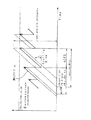
続いて、従来の第3の編集処理について図18を用いて説明する。この従来の第3の編集処理では、図18(a)に示すように、メインストリームの接続点(Splice Point)を、復号器による最後のピクチャの引き抜きタイミング(時刻t151)とし、かつ、VBVバッファのビット占有量が零となるタイミングとしている。また、この従来の第3の編集処理では、図18(b)に示すように、サブストリームの接続点(Splice Point)を、VBVバッファへの供給の開始のタイミング(時刻t161)としている。そして、第3の編集処理では、メインストリームとサブストリームの各接続点同士を時刻151においてつなぎ合わせることにより、例えば、図18(c)に示すような、時刻t151までメインストリームのピクチャが復号器により引き抜かれ、時刻t152以降サブストリームのピクチャが復号器により引き抜かれる1つのスプライスドストリームを生成している。
【0023】
しかしながら、この従来の第3の編集処理では、メインストリームの最後のピクチャが引き抜かれてからサブストリームの供給が開始されるので、VBVバッファがオーバフローやアンダーフローすることはないが、復号器がピクチャを引き抜くことができない時間帯(時刻t151〜時刻t152)が生じてしまっていた。また、同様に、メインストリームの最後のピクチャが供給されたタイミング(時刻t150)からサブストリームの供給が開始されるまでの、VBVバッファにデータが供給されない時間帯(時刻t150〜時刻t151)が生じてしまっていた。従って、この第3の編集処理では、MPEGストリームの連続性を保つことができず、復号器側の処理に対して制約が生じていまい、安定した復号処理を行うことができなかった。
【0024】
本発明は、このような実情を鑑みてなされたものであり、復号器の入力バッファを破綻させることなくかつ復号器の処理に制約を与えることがないように、2つの圧縮画像データのデータストリームを任意の接続点で接続して、連続した1つの圧縮画像データストリーム圧縮画像データを生成する圧縮画像データの編集装置及び圧縮画像データの編集方法を提供することを目的とする。
【0025】
【課題を解決するための手段】
上述の課題を解決するために、本発明に係る圧縮画像データの編集装置は、MPEGビデオ方式で符号化された第1の圧縮画像データのデータストリーム(第1のエレメンタリストリーム)の任意の接続点と、MPEGビデオ方式で符号化された第2の圧縮画像データのデータストリーム(第2のエレメンタリストリーム)の任意の接続点とを接続して、連続した1つの圧縮画像データのデータストリームを生成する圧縮画像データの編集装置であって、第1のエレメンタリストリームの任意の接続点と第2のエレメンタリストリームの任意の接続点との間に、MPEGビデオ方式で符号化された所定の圧縮画像データとスタッフィングバイトとを有する挿入圧縮画像データのデータストリーム(挿入エレメンタリストリーム)を挿入して、この第1と第2のエレメンタリストリームを接続する接続手段と、MPEGビデオ方式で符号化されたデータストリームのVBV( Video Buffering Verifier )のVBVディレイ( VBV_delay )と、ビットレート( bitrate )と、このVBVディレイのクロック周波数( frequency )とから、
VBV_delay ×( bitrate / frequency )
を演算することにより、第1のエレメンタリストリームの任意の接続点におけるVBVバッファに対するビット占有量と、第2のエレメンタリストリームの任意の接続点におけるVBVバッファに対するビット占有量と、挿入エレメンタリストリームのVBVバッファに対するビット占有量とを検出し、これら検出したビット占有量に基づき接続手段を制御する制御手段とを備え、制御手段は、挿入エレメンタリストリームの圧縮画像データの枚数とスタッフィングバイトのデータ量を制御して、挿入エレメンタリストリームの最初のVBVバッファに対するビット占有量を、第1のエレメンタリストリームの任意の接続点におけるVBVバッファに対するビット占有量に一致させ、挿入エレメンタリストリームの最後のVBVバッファに対するビット占有量を、第2のエレメンタリストリームの任意の接続点におけるVBVバッファに対するビット占有量に一致させることを特徴とする。
【0029】
本発明に係る圧縮画像データの編集方法は、任意の接続点までのMPEGビデオ方式で符号化された第1の圧縮画像データのデータストリーム(第1のエレメンタリストリーム)を入力し、MPEG2ビデオ方式で符号化された所定の圧縮画像データとスタッフィングバイトとを有する挿入圧縮画像データのデータストリーム(挿入エレメンタリストリーム)を入力し、任意の接続点からのMPEGビデオ方式で符号化された第2の圧縮画像データのデータストリーム(第2のエレメンタリストリーム)を入力し、MPEGビデオ方式で符号化されたデータストリームのVBV( Video Buffering Verifier )のVBVディレイ( VBV_delay )と、ビットレート( bitrate )と、このVBVディレイのクロック周波数( frequency )とから、
VBV_delay ×( bitrate / frequency )
を演算することにより、第1のエレメンタリストリームの任意の接続点におけるVBVバッファに対するビット占有量と、第2のエレメンタリストリームの任意の接続点におけるVBVバッファに対するビット占有量と、挿入エレメンタリストリームのVBVバッファに対するビット占有量とを検出して、これら検出したビット占有量に基づき、挿入エレメンタリストリームの圧縮画像データの枚数とスタッフィングバイトのデータ量を制御して、挿入エレメンタリストリームの最初のVBVバッファに対するビット占有量を、第1のエレメンタリストリームの任意の接続点におけるVBVバッファに対するビット占有量に一致させ、挿入エレメンタリストリームの最後のVBVバッファに対するビット占有量を、第2のエレメンタリストリームの任意の接続点におけるVBVバッファに対するビット占有量に一致させて、第1のエレメンタリストリームの任意の接続点と第2のエレメンタリストリームの任意の接続点との間に、挿入エレメンタリストリームを挿入して、この第1と第2のエレメンタリストリームを接続することを特徴とする。
【0033】
【発明の実施の形態】
以下、本発明を適用した実施の形態の圧縮画像データの編集装置について、図面を参照しながら説明する。
【0034】
この本発明の実施の形態の編集装置は、MPEG2ビデオ方式で画像圧縮された第1の圧縮画像データのデータストリーム(第1のエレメンタリストリーム)の任意のピクチャの後ろに、任意のピクチャから始まるMPEG2ビデオ方式で画像圧縮された第2の圧縮画像データのデータストリーム(第2のエレメンタリストリーム)をつなぎ合わせ、1つのスプライスドストリームを生成する装置である。
【0035】
例えば、この本発明の実施の形態の編集装置1は、図1に示すように、第1のエレメンタリストリーム(以下、メインストリームと呼ぶ。)が映画等をMPEG2ビデオ方式で画像圧縮したものであり、第2のエレメンタリストリーム(以下、サブストリームと呼ぶ。)が短時間のコマーシャル等をMPEG2ビデオ方式で画像圧縮したものである場合に、映画等に対して、コマーシャル等を適時挿入して1つの番組のデータストリームを生成するといった処理等を行う。また、この本発明の実施の形態の編集装置1は、図2に示すように、放送局の本局から伝送された映画やニュース等を受信して、地方コマーシャル,地方天気予報又は生中継映像等を挿入して地方用の番組を生成するといった放送局の支局で行われる処理等を行う。
【0036】
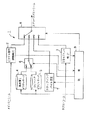
図3に、この本発明の実施の形態の編集装置のブロック構成図を示す。
【0037】
編集装置1には、任意のピクチャでデータが終了するメインストリームと、任意のピクチャからデータが開始するサブストリームとが例えば図示しないサーバー等から供給される。このメインストリームとサブストリームのそれぞれの任意のピクチャ、すなわち、メインストリームの最後のピクチャとサブストリームの最初のピクチャは、例えば、この編集装置1を用いて編集操作を行っているユーザ等により設定される。ユーザ等により設定されたこれらピクチャに基づきメインストリームの接続点(Splice Point)と、サブストリームの接続点(Splice Point)とが定められ、この編集装置1によりこの接続点同士が接続され、2つのストリームが1つのデータストリームが生成される。
【0038】
この編集装置1は、メインストリームの最後のピクチャの次に伝送すべきピクチャのVBVディレイを検出するピクチャ復号時間検出部2と、サブストリームの最初のピクチャのVBVディレイを検出するVBVディレイ検出部3と、黒画像のIピクチャを格納した黒画像Iピクチャサーバ4と、リピートPピクチャを格納したリピートPピクチャサーバ5と、黒画像IピクチャとリピートPピクチャを切り換えるピクチャ切換スイッチ6と、スタッフィングバイトを発生するスタッフィングバイト発生部7と、メインストリーム,サブストリーム,黒画像Iピクチャ又はリピートPピクチャ,スタッフィングバイトが供給されこれらを切り換えて1つのスプライスドストリームを生成するマルチプレクサ8と、各部の制御を行う制御部9とを備えている。
【0039】
ピクチャ復号時間検出部2には、任意のピクチャでデータが終了するすなわち接続点(Splice Point)でデータが終了するメインストリームが供給される。このピクチャ復号時間検出部2は、この最後のピクチャの次に伝送すべきピクチャのVBVディレイを検出する。すなわち、ピクチャ復号時間検出部2は、メインストリームの接続点の直後に接続されるピクチャのVBVディレイを検出する。
【0040】
具体的に、所定のピクチャの次に伝送されるピクチャのVBVディレイ(next_vbv_delay)は、この所定のピクチャのVBVディレイ(vbv_delay)と、その所定のピクチャのイメージサイズ(image_size)と、デコード管理時間(Decode Time Stamp)の間隔であるΔDTSと、伝送するデータストリームのビットレート(bitrate)とから、以下の式(1)により求めることができる。
【0041】
next_vbv_delay=vbv_delay −(image_size/bitrate)+ΔDTS・・・(1)
【0042】
従って、メインストリームの最後のピクチャの次に伝送すべきピクチャのVBVディレイ(next_vbv_delay)は、メインストリームの最後のピクチャのVBVディレイ(last_vbv_delay)と、この最後のピクチャのイメージサイズ(image_size)と、デコード管理時間(Decode Time Stamp)の間隔であるΔDTSと、メインストリームのビットレート(bitrate)とから、以下の式(2)により求めることができる。
【0043】

なお、図4に、メインストリームのVBVバッファに対するビット占有量の推移を示すとともに、この式(2)に示した各パラメータを示す。
【0045】
ピクチャ復号時間検出部2は、以上のように求めたメインストリームの最後のピクチャの次に復号するピクチャのVBVディレイ(next_vbv_delay)を、制御部9に供給する。
【0046】
VBVディレイ検出部3には、任意のピクチャからデータが開始するサブストリームが供給される。ピクチャ復号時間検出部2は、サブストリームの最初のピクチャのVBVディレイ(first_vbv_delay)を検出する。
【0047】
図5に、サブストリームのVBVバッファに対するビット占有量の推移を示すとともに、このサブストリームの最初のピクチャのVBVディレイ(first_vbv_delay)を示す。
【0048】
VBVディレイ検出部3は、検出したサブストリームの最初のピクチャのVBVディレイ(first_vbv_delay)を、制御部9に供給する。
【0049】
黒画像Iピクチャサーバ4は、黒画像のIピクチャのピクチャデータを格納しており、制御部9の制御に基づきこの黒画像のIピクチャを出力する。
【0050】
リピートPピクチャサーバ5は、全てのマクロブロックがスキップトマクロブロックから構成されるPピクチャ(以下、リピートPピクチャと呼ぶ。)のピクチャデータを格納している。ここで、MPEG2では、何も情報を必要としないマクロブロックのことをスキップトマクロブロック(Skipped MB)と呼んでいる。このスキップトマクロブロックは、符号化がされていないマクロブロックであり、このスキップトマクロブロックを復号した場合には1つ前のマクロブロックの情報が繰り返されることとなる。リピートPピクチャは、全てのマクロブロックがこのようなスキップトマクロブロックから構成されているものである。
【0051】
リピートPピクチャサーバ5は、制御部9の制御に基づき、格納しているリピートPピクチャを出力する。
【0052】
ピクチャ切換スイッチ6は、制御部9の制御に基づき、黒画像Iピクチャサーバ4或いはリピートPピクチャサーバ5から出力される黒画像Iピクチャ又はリピートPピクチャを切り換える。
【0053】
スタッフィングバイト発生部7は、MPEGストリームの符号化において、符号発生量が少ない場合に生成される擬似データであるスタッフィングバイト(Stuffing_Byte)を発生する。このスタッフィングバイトは、特に何等意味を持たないデータであり、復号器側で読み捨てられるものである。
【0054】
このスタッフィングバイトの符号量、出力タイミングは、制御部9により制御される。
【0055】
マルチプレクサ8は、メインストリーム,サブストリーム,黒画像Iピクチャ又はリピートPピクチャ,スタッフィングバイトが供給されこれらを切り換えて1つのスプライスドストリームを生成する。具体的には、マルチプレクサ8は、図6に示すように、メインストリームの接続点(Splice Point)とサブストリームの接続点(Splice Point)との間に、黒画像Iピクチャ,リピートPピクチャ,スタッフィングバイト等を有する挿入圧縮画像データのデータストリーム(以下、挿入ストリームと呼ぶ。)を挿入して、1つのスプライスドストリームを生成する。
【0056】
制御部9は、上述した各部の制御及び監視を行い、上記マルチプレクサ8及びピクチャ切換スイッチ6の切り換えの制御を行う。
【0057】
つぎに、メインストリームとサブストリームとの間に挿入する挿入ストリームについてさらに説明する。
【0058】
制御部9は、図7に示すように、メインストリームの最後のピクチャ、すなわち、接続点(Splice Point)までのデータを伝送し終えると、マルチプレクサ8を切り換えて、黒画像Iピクチャサーバ4に格納された黒画像Iピクチャを、挿入ストリームとして続けて伝送する。このとき、ピクチャ復号時間検出部2が検出したメインストリームの最後のピクチャの次に伝送するピクチャのVBVディレイ(next_vbv_delay)に基づき、この黒画像Iピクチャのビット占有量(first_picture_occupancy)を求めてピクチャヘッダに書き込む。
【0059】
なお、各ピクチャのビット占有量(occupancy)は、以下の式(3)により求められる。
【0060】
occupancy=vbv_delay×bitrate/frequency ・・・(3)
ここで、vbv_delayは、そのピクチャのVBVディレイであり、frequencyは、VBVディレイを表すためのクロック周波数である。このfrequencyは、例えば、90kHz単位で示されている。
【0061】
このことから、この黒画像Iピクチャのビット占有量(first_picture_occupancy)は、ピクチャ復号時間検出部2により検出されたメインストリームの最後のピクチャの次に復号するピクチャのVBVディレイ(next_vbv_delay)から、以下の式(4)により求められる。
【0062】
編集装置1では、以上のように求めたメインストリームの最後のピクチャの次に復号するピクチャのVBVディレイ(next_vbv_delay)を、挿入ストリームの最初のピクチャのビット占有量(first_picture_occupancy)としてピクチャヘッダに書き込むことによって、メインストリームと挿入ストリームとを連続的に接続することができる。そして、このように接続したスプライスドストリームでは、入力バッファが破綻することなく、また、何等処理に制約を設けずに復号できる。
【0064】
制御部9は、この黒画像Iピクチャを伝送し終えると、ピクチャ切換スイッチ6を切り換えて、リピートPピクチャサーバ5に格納されたリピートPピクチャの伝送を行う。制御部9は、このリピートPピクチャを、黒画像Iピクチャの後に続けて予め設定された枚数だけ順次伝送していく。すなわち、制御部9は、つなぎ合わせるメインストリームとサブストリームとの時間間隔等を予め設定しておき、この挿入ストリームの表示時間や伝送時間を求め、その間隔に応じた枚数のリピートPピクチャを伝送する。
【0065】
なお、ここで、制御部9は、各リピートPピクチャの伝送を行う際に、ビット占有量(occupancy)がVBVバッファサイズ(vbv_buffer_size)を越えないように、すなわち、この挿入ストリームがVBVバッファに対して破綻しないように監視を行う。制御部9は、挿入ストリームがオーバーフローしてしまう場合には、マルチプレクサ8を切り換えて、スタッフィングバイト発生部7が発生するスタッフィングバイトを各リピートPピクチャとともに伝送する。
【0066】
具体的に、このスタッフィングバイトのデータ量は、図8及び以下に示すように求めることができる。
【0067】
まず、制御部9は、次に伝送するリピートPピクチャのVBVディレイ(next_vbv_delay)を、各リピートPピクチャのVBVディレイ(vbv_delay)及びイメージサイズ(image_size)から、以下の式(1)により求める。
【0068】
次に伝送するリピートPピクチャのビット占有量(next_picture_occupancy)を、求めたVBVディレイ(next_vbv_delay)から、以下の式(5)により求める。
【0070】
そして、各ピクチャに挿入するスタッフィングバイトのデータ量は、次に伝送するリピートPピクチャのビット占有量(next_picture_occupancy)とVBVバッファサイズ(vbv_buffer_size)の差から、以下の式(6)のように求めることができる。
【0072】
stuffing_Byte=vbv_buffer_size−next_picture_occupancy ・・・(6)
【0073】
例えば、next_vbv_delayが55,048、bitrateが3,000,000BPS、vbv_buffer_sizeが1,835,008bit、frequencyが90kHzの場合、スタッフィングバイトのデータ量は以下のように求められる。
【0074】
next_picture_occupancy=55048×3000000/90000=1834933
stuffing_Byte =1835008−1834933=75 bit=9.4 Byte
【0075】
編集装置1では、以上のようにリピートPピクチャを伝送する際に、挿入ストリームとVBVバッファサイズを監視しながら、リピートPピクチャとスタッフィングバイトの挿入を繰り返し、MPEGストリームとして連続した挿入ストリームを生成することにより、VBVバッファを破綻させることなくスプライスドストリームを生成することができる。
【0076】
続いて、制御部9は、図9に示すように、所定枚数分のリピートPピクチャを伝送し終えると、すなわち、挿入ストリームの接続点(Splice Point)までのデータを伝送し終えると、マルチプレクサ8を切り換えてサブストリームの伝送を開始する。このとき、制御部9は、VBVディレイ検出部3が検出したサブストリームの最初のピクチャのVBVディレイ(first_vbv_delay)に基づき、挿入ストリームの最後のピクチャに挿入するスタッフィングバイトのデータ量を調整して、挿入ストリームとサブストリームとを接続する。
【0077】
具体的に、制御部9は、この挿入ストリームの最後のピクチャに挿入するスタッフィングバイトのデータ量は、以下のように求める。
【0078】
まず、制御部9は、挿入ストリームとサブストリームとの接続点(Spice Point)におけるビット占有量であるデコードサイズ(first_picture_decode_size)を、以下の式(7)により求める。
【0079】
そして、この制御部9は、このデコードサイズ(first_picture_decode_size)と挿入ストリームの最後のピクチャのビット占有量(last_picture_occupancy)から、この挿入ストリームの最後のピクチャに挿入するスタッフィングバイト(staffing_Byte)を以下の式(8)により求める。
【0081】
編集装置1では、以上のように求めたスタッフィングバイトを挿入ストリームの最後のピクチャとともに挿入することによって、挿入ストリームとサブストリームとを連続的に接続することができる。そして、このように接続したスプライスドストリームでは、入力バッファが破綻することなく、また、何等処理に制約を設けずに復号できる。
【0083】
以上、メインストリームとサブストリームとの間に挿入する挿入ストリームについて説明したが、この挿入ストリームは、例えば、以下に説明するようなものであってもよい。
【0084】
すなわち、この挿入ストリームでは、先頭のIピクチャは黒画像に限られない。つまり、挿入ストリームの先頭の画像は、あらゆる画像であってもよく、その色彩や画像の内容は限られない。例えば、黒画像を先頭に挿入した場合には、このメインストリームとサブストリームと間には、黒画像がモニタに表示されることとなるが、例えば、青画像や、緑画像又は所定のコメントや静止画像等もこのメインストリームとサブストリームと間に表示することもできる。
【0085】
また、この挿入ストリームでは、このIピクチャを挿入せず、先頭からリピートPピクチャの挿入を行っても良い。この場合には、メインストリームの最後の画像がフリーズされて表示されることとなる。
【0086】
また、この挿入ストリームでは、リピートPピクチャは固定枚数に限られず、その枚数をメインストリームとサブストリームとの関係により可変としても良い。例えば、図10に示すように、挿入ストリームとサブストリームとの接続点(Splice Point)のデコードサイズ(first_picture_decode_size)を、先の式(7)により求める。同様に、メインストリームとサブストリームとの接続点(Splice Point)のデコードサイズ(decode_size)を求める。そして、リピートPピクチャを一枚挿入すると、一定のビット占有量(occupancy)が増加されることから、挿入ストリームとサブストリームとの接続点(Splice Point)のデコードサイズ(first_picture_decode_size)と、メインストリームとサブストリームとの接続点(Splice Point)のデコードサイズ(decode_size)との差に基づき、挿入するリピートPピクチャの最低必要となる枚数を計算する。この場合、挿入ストリームに含まれるリピートPピクチャの枚数が最小となるように設定することができる。
【0087】
つぎに、この編集装置1の処理内容を、図11及び図12に示すフローチャートを用いて説明する。
【0088】
まず、図11に示すステップS1において、この編集装置1にメインストリームが供給されると、このメインストリームの最後のピクチャの次に伝送されるピクチャのVBVディレイ(next_vbv_delay)を、先の式(2)により求める。
【0089】
続いてステップS2において、挿入ストリームの最初のピクチャにIピクチャを挿入するか、或いは、リピートPピクチャを挿入するか判断する。Iピクチャを挿入する場合には、ステップS3に進み、リピートPピクチャを挿入する場合には、ステップS4に進む。
【0090】
続いてステップS3において、例えば、黒画像等のIピクチャを挿入する。このとき、この黒画像Iピクチャのビット占有量(first_picture_occupancy)を先の式(4)により求めてピクチャヘッダに書き込む。また、次のリピートPピクチャのビット占有量(next_picture_occupancy)がVBVバッファサイズ(vbv_buffer_size)を越えている場合には、先の式(6)によりスタッフィングバイト(stuffing_Byte)を求めて挿入する。このステップS3からステップS4に進む。
【0091】
続いてステップS4において、挿入するリピートPピクチャの枚数が固定であるか、最小の枚数とするかを判断する。リピートPピクチャの枚数が固定である場合にはステップS5に進み、リピートPピクチャの枚数を最小にする場合には図12に示すステップS10に進む。
【0092】
ステップS5において、リピートPピクチャを挿入する。
【0093】
続いてステップS6において、次のリピートPピクチャのビット占有量(next_picture_occupancy)を計算する。
【0094】
続いてステップS7において、次のリピートPピクチャのビット占有量(next_picture_occupancy)がVBVバッファサイズ(vbv_buffer_size)を越えているかどうかを判断する。越えている場合には、ステップS8において先の式(6)によりスタッフィングバイト(stuffing_Byte)を求めて挿入し、ステップS9に進む。また、越えていない場合には、そのままステップS9に進む。
【0095】
続いてステップS9において、設定された枚数分のリピートPピクチャの挿入が終了したかどうかを判断する。設定された枚数分のリピートPピクチャを挿入した場合には、ステップS16に進み、設定された枚数分のリピートPピクチャを挿入していない場合には、ステップS5からの処理を繰り返す。
【0096】
一方、図12に示すステップS10において、挿入ストリームとサブストリームとの接続点(Splice Point)のデコードサイズ(first_picture_decode_size)と、メインストリームとサブストリームとの接続点(Splice Point)のデコードサイズ(decode_size)を求める。
【0097】
続いてステップS11において、リピートPピクチャを挿入する。
【0098】
続いてステップS12において、次のリピートPピクチャのビット占有量(next_picture_occupancy)を計算する。
【0099】
続いてステップS13において、次のリピートPピクチャのビット占有量(next_picture_occupancy)がVBVバッファサイズ(vbv_buffer_size)を越えているかどうかを判断する。越えている場合には、ステップS14において先の式(6)によりスタッフィングバイト(stuffing_Byte)を求めて挿入し、ステップS15に進む。また、越えていない場合には、そのままステップS15に進む。
【0100】
続いてステップS15において、現在のデコードサイズが、挿入ストリームとサブストリームとの接続点(Splice Point)のデコードサイズ(first_picture_decode_size)を越えているかどうかを判断する。越えていると判断する場合には、図11に示すステップS16に進み、越えていないと判断する場合には、ステップS10からの処理を繰り返す。
【0101】
図11に示すステップS16において、サブストリームの最初のピクチャのVBVディレイ(first_vbv_delay)を検出する。
【0102】
続いてステップS17において、挿入ストリームの最後のピクチャに挿入するスタッフィングバイト(staffing_Byte)を、先の式(8)により求め、求めたデータ量のスタッフィングバイトを挿入する。
【0103】
そして、挿入ストリームとサブストリームとを接続点(Splice Point)で接続して処理を終了する。
【0104】
以上のステップS1からステップS17までの処理を行うことによって、編集装置1では、メインストリームとサブストリームとの間に挿入ストリームを挿入し、連続したスプライスドストリームを生成する。
【0105】
以上のように本発明の実施の形態の編集装置1では、ストリームの最初のVBVバッファに対するビット占有量を、メインストリームと接続点(Splice Point)におけるVBVバッファに対するビット占有量に一致させ、かつ、ストリームの最後のVBVバッファに対するビット占有量を、サブストリームの任意の接続点(Splice Point)におけるVBVバッファに対するビット占有量に一致させた挿入ストリームを生成することができる。
【0106】
このことにより、この編集装置1では、VBVバッファを破綻させることなく、メインストリームとサブストリームをそのまま連続的に接続することができる。そのため、この2つのストリームを接続したスプライスドストリームを復号する場合においても、入力段に設けられたバッファの破綻、すなわち、オーバフロー及びアンダーフローが生じないとともに、何等制約がされずに処理を行うことができる。
【0107】
なお、編集装置1では、メインストリームとサブストリームの供給端子の入れ替えを行うことにより、例えば、図13に示すように、映画等の連続した動画像の一部にコマーシャルを挿入するといった処理を行うことができる。すなわち、まず、映画等の画像データの前半部分をメインストリームとし、コマーシャルをサブストリームとして、この映画の前半部分にコマーシャルを接続する。続いて、映画の前半部分が接続されているコマーシャルをメインストリームとし、映画の後半部分をサブストリームとして、このコマーシャルに、映画の後半部分を接続する。このことにより、編集装置1では、映画等の連続した動画像の一部分にコマーシャルを挿入することができる。
【0108】
【発明の効果】
本発明では、最初のVBVバッファに対するビット占有量を第1のエレメンタリストリームの任意の接続点におけるVBVバッファに対するビット占有量に一致させ、最後のVBVバッファに対するビット占有量を第2のエレメンタリストリームの任意の接続点におけるVBVバッファに対するビット占有量に一致させた挿入エレメンタリストリームを、第1と第2のエレメンタリストリームの間に挿入し、連続した1つの圧縮画像データのデータストリームを生成する。
【0109】
このことにより、本発明では、VBVバッファを破綻させることなく、MPEGビデオ方式で符号化された2つの圧縮画像データのデータストリームをそのまま連続的に接続することができる。そのため、この2つの圧縮画像データを接続したエレメンタリストリームを復号する場合においても、入力段に設けられたVBVバッファの破綻、すなわち、オーバフロー及びアンダーフローが生じないとともに処理に制約がされず、通常通りの処理を行うことができる。
【0110】
また、本発明では、圧縮画像データとともにスタッフィングバイトを挿入した挿入エレメンタリストリームを、第1と第2のエレメンタリストリームの間に挿入し、連続した1つの圧縮画像データのデータストリームを生成することにより、VBVバッファを破綻しない挿入エレメンタリストリームを、第1と第2のエレメンタリストリームの間に挿入することができる。
【0111】
また、本発明に係る圧縮画像データの編集装置及び圧縮画像データの編集方法では、挿入エレメンタリストリームとして画面内予測符号化画像やリピートピクチャ等を挿入することにより、第1と第2のエレメンタリストリームの接続点間の挿入エレメンタリストリームを表示させている際に、第1の圧縮画像データの任意の接続点の画像を静止させて表示させることや、また、例えば、黒画像等の任意の画像を表示させることができる。
【図面の簡単な説明】
【図1】本発明の実施の形態の編集装置の適用例を説明する為の図である。
【図2】本発明の実施の形態の編集装置の適用例を説明する為の図である。
【図3】本発明の実施の形態の編集装置のブロック構成図である。
【図4】上記編集装置に供給されるメインストリームのVBVバッファに対するビット占有量の推移を示す図である。
【図5】上記編集装置に供給されるサブストリームのVBVバッファに対するビット占有量の推移を示す図である。
【図6】上記編集装置が生成するスプライスドストリームのVBVバッファに対するビット占有量の推移を示す図である。
【図7】上記編集装置が生成するスプライスドストリームのメインストリームと挿入ストリームの接続点におけるVBVバッファに対するビット占有量の推移を示す図である。
【図8】上記編集装置が生成する挿入ストリームのVBVバッファに対するビット占有量の推移を示す図である。
【図9】上記編集装置が生成するスプライスドストリームの挿入ストリームとサブストリームの接続点におけるVBVバッファに対するビット占有量の推移を示す図である。
【図10】上記編集装置が生成するスプライスドストリームのVBVバッファに対するビット占有量の推移を示す図である。
【図11】上記編集装置の処理内容を示すフローチャートである。
【図12】上記編集装置の処理内容を示すフローチャートである。
【図13】上記編集装置により、映画等の連続した画像データにコマーシャルを挿入する処理を説明するための図である。
【図14】復号器の前段に設けられる入力バッファにMPEGストリームが供給された場合における、この入力バッファに対するMPEGストリームのビット占有量の推移を示す図である。
【図15】1つの長時間の映画等に対して、短時間のコマーシャル等を挿入して番組を作製するといった編集処理を説明する為の図である。
【図16】従来の編集処理におけるメインストリームのVBVバッファに対するビット占有量、サブストリームのVBVバッファに対するビット占有量、スプライスドストリームのVBVバッファに対するビット占有量を示す図である。
【図17】従来の編集処理におけるメインストリームのVBVバッファに対するビット占有量、サブストリームのVBVバッファに対するビット占有量、スプライスドストリームのVBVバッファに対するビット占有量を示す図である。
【図18】従来の編集処理におけるメインストリームのVBVバッファに対するビット占有量、サブストリームのVBVバッファに対するビット占有量、スプライスドストリームのVBVバッファに対するビット占有量を示す図である。
【符号の説明】
1 編集装置、2 ピクチャ復号時間検出部、3 VBVディレイ検出部、4黒画像Iピクチャサーバ、5 リピートPピクチャサーバ、6 ピクチャ切換スイッチ、7 スタッフィングバイト発生部、8 マルチプレクサ、9 制御部[0001]
BACKGROUND OF THE INVENTION
The present invention relates to an apparatus for editing compressed image data and a method for editing compressed image data used in a video conference system, a television telephone system, a digital broadcasting system, and the like, and in particular, arbitrarily connects two compressed image data streams. The present invention relates to a compressed image data editing apparatus and a compressed image data editing method, which are connected at points and generate a data stream of one continuous compressed image.
[0002]
[Prior art]
In recent years, development of digital video transmission systems such as digital broadcasting systems and television telephone systems has been progressing. In such a moving image transmission system using a digital method, generally, moving image data compressed by the MPEG2 video method or the like is handled.
[0003]
This MPEG is the accumulation of ISO / IEC JTC1 / SC29 (International Organization for Standardization / International Electrotechnical Commission, Joint Technical Committee 1 / Sub Committee 29: International Organization for Standardization / International Electrotechnical Commission Joint Technical Committee 1 / Special Committee 29) This is an abbreviation for an organization for studying moving image encoding, and ISO11172 is standardized as the MPEG1 standard and ISO13818 is standardized as the MPEG2 standard. Also, in these international standards, ISO11172-1 and ISO13818-1 are items for system multiplexing, ISO11172-2 and ISO13818-2 are items for video coding, and ISO11172-3 and ISO13818 are items for audio coding. -3 is standardized.
[0004]
Here, in the MPEG2 video (ISO13818-2) standard, when the input compressed image data is decoded, the encoding process is performed so that the input buffer provided in the preceding stage of the decoder does not underflow or overflow. In addition, it is stipulated that the capacity of an input buffer provided in the preceding stage of the decoder is virtually assumed in advance and the amount of code generated is controlled so that the input buffer does not fail. In this MPEG2 video standard, such a virtual buffer for controlling the amount of generated code is defined as a VBV (Video Buffering Verifier) buffer, and the capacity of this VBV buffer is defined as a VBV buffer size (vbv_buffer_size). Yes.
[0005]
Specifically, the function of this VBV buffer will be described with reference to FIG. FIG. 14 shows the transition of the amount of data stored in the input buffer when the MPEG stream is supplied to the input buffer provided in the preceding stage of the decoder. The horizontal axis of FIG. 14 indicates time, and the decoding timing (t of each picture included in the supplied MPEG stream (t101, T102, T103...) is entered. The vertical axis indicates the amount of data (bit occupancy) stored in the input buffer.
[0006]
The input buffer sequentially stores MPEG streams that have been image-compressed using the MPEG2 video system in accordance with the bit rate.
[0007]
First, the supply time t100Time t when vbv_delay time has passed since101The first picture is extracted by the decoder for decoding.
[0008]
Here, this vbv_delay indicates the time until the amount of data stored in the input buffer becomes the initial state when predetermined picture data is acquired by random access and the picture is decoded. Data indicating this vbv_delay is stored in the picture layer of the MPEG stream, and for example, the time is represented using a clock of 90 kHz.
[0009]
The picture data amount extracted by the decoder is the sum of the picture data size (picture_size), the picture start code data size (picture_start_code), and the sequence header data size (sequence_header). The data amount obtained by adding picture_size, picture_start_code, and sequence_header is hereinafter referred to as an image size (image_size).
[0010]
Then, this time t101Thereafter, MPEG streams continue to be sequentially supplied to the input buffer according to a predetermined bit rate. And this time t101Each time t elapses every ΔDTS, which is the interval of the decode management time (Decode Time Stamp)102, Time t103···Times of Dayn,Times of Dayn + 1.., The data corresponding to the image size of each picture is extracted by the decoder.
[0011]
As described above, in the input buffer provided in the preceding stage of the decoder, the MPEG stream is sequentially stored according to the bit rate, and the decoding timing of each picture (time t101, Time t102, Time t103..)), Data corresponding to the image size of the picture is extracted by the decoder.
[0012]
Here, if the difference between the total data amount of the supplied MPEG stream and the total data amount of the image size of the picture extracted at each decoding timing becomes larger than the buffer size of this input buffer, this input buffer overflows. End up. On the other hand, if the total data amount of the image size of the picture extracted at each decoding timing becomes larger than the total data amount of the supplied MPEG stream, this input buffer will underflow.
[0013]
Therefore, in the MPEG2 video (ISO13818-2) standard, when encoding an MPEG stream, the capacity of the input buffer provided in the preceding stage of the decoder is virtually assumed as the VBV buffer size (vbv_buffer_size), and this VBV It is specified that the amount of generated code is controlled so that no failure occurs with respect to the buffer size.
[0014]
[Problems to be solved by the invention]
By the way, in a broadcasting station or the like that broadcasts a moving image compressed by the MPEG2 method, an editing process is generally performed by connecting two or more moving image data into one moving image data. For example, as shown in FIG. 15, a broadcasting station or the like performs an editing process such as inserting a short-time commercial or the like into movie moving image data.
[0015]
In particular, when such editing processing is performed, from the viewpoint of real-time transmission and ease of processing, the baseband moving image data is not handled and editing processing is performed, but the MPEG stream is not decoded. An editing process that directly handles a compressed image has been performed.
[0016]
Hereinafter, a first compressed image data stream (hereinafter referred to as a main stream) compressed by the MPEG2 video system and a second compressed image data stream (hereinafter, referred to as a main stream) compressed by the MPEG2 video system. Hereinafter, the conventional first to third editing processes for connecting one substream and generating one spliced stream will be described.
[0017]
16 to 18 used for explaining the conventional first to third editing processes, the bit occupancy for the main stream VBV buffer, the bit occupancy for the substream VBV buffer, and the splice, respectively. It is assumed that the bit occupancy for the stream VBV buffer is shown.
[0018]
First, the conventional first editing process will be described with reference to FIG. In the first conventional editing process, as shown in FIG. 16A, the connection point (Splice Point) for joining the main streams is set to the end timing of supply to the VBV buffer (time t111). Also, in the first conventional editing process, as shown in FIG. 16B, the connection point (Splice Point) of the substream is set to the start timing of supply to the VBV buffer (time t121). Then, in the first editing process, the connection points of the main stream and the substream are connected at time t.111For example, the time t as shown in FIG.112Until the picture of the main stream is extracted by the decoder until time t112Thereafter, one spliced stream in which the picture of the substream is extracted by the decoder is generated.
[0019]
However, the spliced stream generated by the conventional first editing process has a difference between the total data amount to be supplied and the total data amount of the picture to be extracted, as indicated by the hatched portion in FIG. May become larger than the VBV buffer size and the VBV buffer may overflow.
[0020]
Next, a conventional second editing process will be described with reference to FIG. In the conventional second editing process, as shown in FIG. 17A, the connection point (Splice Point) of the main stream is set to the extraction timing (time t) of the last picture by the decoder.131). In the second editing process of the related art, as shown in FIG. 17 (b), the connection point (Splice Point) of the substream is set as the bit occupancy of the VBV buffer at the connection point of the main stream. Timing that is the same as the occupation amount (time t141). Then, in the second editing process, the connection points of the main stream and the sub stream are131For example, the time t as shown in FIG.131Until the picture of the main stream is extracted by the decoder until time t131Thereafter, one spliced stream in which the picture of the substream is extracted by the decoder is generated.
[0021]
However, in the conventional second editing process, the first picture of the substream is extracted with the VBV delay (next_vbv_delay) of the picture next to the picture extracted at the end of the main stream. As indicated by the hatched portion of (), there is a possibility that the total data amount of the picture extracted is larger than the total data amount supplied and the VBV buffer underflows. That is, the VBV delay (next_vbv_delay) of the picture next to the picture extracted at the end of the main stream is shorter than the VBV delay (first_vbv_delay) of the picture extracted at the beginning of the substream, and the VBV buffer may underflow. There was sex.
[0022]
Next, a conventional third editing process will be described with reference to FIG. In this conventional third editing process, as shown in FIG. 18A, the connection point (Splice Point) of the main stream is set to the timing of extracting the last picture by the decoder (time t151And the timing at which the bit occupation amount of the VBV buffer becomes zero. Further, in the third editing process of the related art, as shown in FIG. 18B, the connection point (Splice Point) of the substream is set to the start timing of supply to the VBV buffer (time t161). Then, in the third editing process, the connection points of the main stream and substream are151By connecting them at time t, for example, as shown in FIG.151Until the picture of the main stream is extracted by the decoder until time t152Thereafter, one spliced stream in which the picture of the substream is extracted by the decoder is generated.
[0023]
However, in the conventional third editing process, since the substream supply is started after the last picture of the main stream is extracted, the VBV buffer does not overflow or underflow. Time zone (time t151~ Time t152) Has occurred. Similarly, the timing at which the last picture of the main stream is supplied (time t150) Until the start of substream supply until no data is supplied to the VBV buffer (time t150~ Time t151) Has occurred. Therefore, in the third editing process, the continuity of the MPEG stream cannot be maintained, the restriction on the process on the decoder side does not occur, and the stable decoding process cannot be performed.
[0024]
The present invention has been made in view of such circumstances, and the data stream of two compressed image data is provided without breaking the decoder input buffer and without restricting the processing of the decoder. The compressed image data editing apparatus and the compressed image data editing method for generating one compressed image data stream compressed image data by connecting them at arbitrary connection points.
[0025]
[Means for Solving the Problems]
In order to solve the above-described problem, an apparatus for editing compressed image data according to the present invention includes:Encoded in MPEG video formatAn arbitrary connection point of the data stream (first elementary stream) of the first compressed image data;Encoded in MPEG video formatAn apparatus for editing compressed image data, which is connected to an arbitrary connection point of a data stream (second elementary stream) of second compressed image data and generates a data stream of one continuous compressed image data. , Between any connection point of the first elementary stream and any connection point of the second elementary stream,Encoded in MPEG video formatPredetermined compressed image data andStuffing byteA connecting means for inserting a data stream (inserted elementary stream) of inserted compressed image data having the following, and connecting the first and second elementary streams;VBV of a data stream encoded in the MPEG video format ( Video Buffering Verifier ) VBV delay ( VBV_delay ) And bit rate ( bitrate ) And the clock frequency of this VBV delay ( frequency And
VBV_delay × ( bitrate / frequency )
By calculatingAt any connection point of the first elementary streamVBVBit occupancy for the buffer and at any connection point of the second elementary streamVBVThe bit occupancy for the buffer and the insertion elementary streamVBVControl means for detecting bit occupancy with respect to the buffer and controlling connection means based on the detected bit occupancy, and the control means includes the number of compressed image data of the inserted elementary stream,Stuffing byteControl the amount of data in the first of the inserted elementary streamsVBVThe bit occupancy for the buffer at any connection point of the first elementary stream.VBVMatch the bit occupancy for the buffer, and the end of the inserted elementary streamVBVThe bit occupancy for the buffer at any connection point of the second elementary stream.VBVIt is characterized in that it matches the bit occupation amount for the buffer.
[0029]
The method for editing compressed image data according to the present invention is provided up to an arbitrary connection point.Encoded in MPEG video formatInput a data stream (first elementary stream) of the first compressed image data,Encoded in MPEG2 video formatPredetermined compressed image data andStuffing byteA data stream (inserted elementary stream) of inserted compressed image data having and from any connection pointEncoded in MPEG video formatInput a data stream (second elementary stream) of the second compressed image data,VBV of a data stream encoded in the MPEG video format ( Video Buffering Verifier ) VBV delay ( VBV_delay ) And bit rate ( bitrate ) And the clock frequency of this VBV delay ( frequency And
VBV_delay × ( bitrate / frequency )
By calculatingAt any connection point of the first elementary streamVBVBit occupancy for the buffer and at any connection point of the second elementary streamVBVThe bit occupancy for the buffer and the insertion elementary streamVBVThe bit occupancy for the buffer is detected, and based on the detected bit occupancy, the number of compressed image data of the inserted elementary stream andStuffing byteControl the amount of data in the first of the inserted elementary streamsVBVThe bit occupancy for the buffer at any connection point of the first elementary stream.VBVMatch the bit occupancy for the buffer, and the end of the inserted elementary streamVBVThe bit occupancy for the buffer at any connection point of the second elementary stream.VBVAn insertion elementary stream is inserted between an arbitrary connection point of the first elementary stream and an arbitrary connection point of the second elementary stream so as to match the bit occupation amount for the buffer. And a second elementary stream are connected.
[0033]
DETAILED DESCRIPTION OF THE INVENTION
Hereinafter, an apparatus for editing compressed image data according to an embodiment to which the present invention is applied will be described with reference to the drawings.
[0034]
The editing apparatus according to the embodiment of the present invention starts from an arbitrary picture after an arbitrary picture of a data stream (first elementary stream) of first compressed image data that has been image-compressed by the MPEG2 video system. This is an apparatus for connecting a data stream (second elementary stream) of second compressed image data compressed by the MPEG2 video system to generate one spliced stream.
[0035]
For example, in the
[0036]
FIG. 3 is a block diagram of the editing apparatus according to the embodiment of the present invention.
[0037]
The
[0038]
The
[0039]
The picture decoding
[0040]
Specifically, the VBV delay (next_vbv_delay) of the picture transmitted next to the predetermined picture includes the VBV delay (vbv_delay) of the predetermined picture, the image size (image_size) of the predetermined picture, and the decoding management time ( It can be obtained by the following equation (1) from ΔDTS which is an interval of Decode Time Stamp) and the bit rate of the data stream to be transmitted.
[0041]
next_vbv_delay = vbv_delay− (image_size / bitrate) + ΔDTS (1)
[0042]
Therefore, the VBV delay (next_vbv_delay) of the picture to be transmitted next to the last picture of the main stream is the VBV delay (last_vbv_delay) of the last picture of the main stream, the image size (image_size) of the last picture, and the decoding. It can be obtained from the following equation (2) from ΔDTS which is the interval of the management time (Decode Time Stamp) and the bit rate of the main stream.
[0043]
FIG. 4 shows the transition of the bit occupancy with respect to the VBV buffer of the main stream, and each parameter shown in the equation (2).
[0045]
The picture decoding
[0046]
The VBV
[0047]
FIG. 5 shows the transition of the bit occupancy with respect to the VBV buffer of the substream and the VBV delay (first_vbv_delay) of the first picture of the substream.
[0048]
The VBV
[0049]
The black image I picture server 4 stores the picture data of the black picture I picture, and outputs the black picture I picture based on the control of the
[0050]
The repeat P picture server 5 stores picture data of a P picture (hereinafter referred to as a repeat P picture) in which all macroblocks are composed of skipped macroblocks. Here, in MPEG2, a macroblock that does not require any information is called a skipped macroblock (Skipped MB). This skipped macroblock is a macroblock that has not been encoded. When this skipped macroblock is decoded, the information of the previous macroblock is repeated. A repeat P picture is one in which all macroblocks are composed of such skipped macroblocks.
[0051]
The repeat P picture server 5 outputs the stored repeat P picture based on the control of the
[0052]
The picture changeover switch 6 switches between a black image I picture or a repeat P picture output from the black image I picture server 4 or the repeat P picture server 5 based on the control of the
[0053]
The
[0054]
The
[0055]
The
[0056]
The
[0057]
Next, the insertion stream inserted between the main stream and the substream will be further described.
[0058]
As shown in FIG. 7, when the
[0059]
The bit occupancy of each picture is obtained by the following equation (3).
[0060]
occupancy = vbv_delay × bitrate / frequency (3)
Here, vbv_delay is a VBV delay of the picture, and frequency is a clock frequency for representing the VBV delay. This frequency is shown in units of 90 kHz, for example.
[0061]
From this, the bit occupation amount (first_picture_occupancy) of this black picture I picture is as follows from the VBV delay (next_vbv_delay) of the picture to be decoded next to the last picture of the main stream detected by the picture
[0062]
In the
[0064]
When the transmission of the black image I picture is completed, the
[0065]
Here, when transmitting each repeat P picture, the
[0066]
Specifically, the data amount of the stuffing byte can be obtained as shown in FIG. 8 and below.
[0067]
First, the
[0068]
Next, the bit occupation amount (next_picture_occupancy) of the repeat P picture to be transmitted is obtained from the obtained VBV delay (next_vbv_delay) by the following equation (5).
[0070]
Then, the data amount of the stuffing byte to be inserted into each picture is obtained from the difference between the bit occupancy amount (next_picture_occupancy) of the repeat P picture to be transmitted next and the VBV buffer size (vbv_buffer_size) as in the following equation (6). Can do.
[0072]
stuffing_Byte = vbv_buffer_size−next_picture_occupancy (6)
[0073]
For example, when next_vbv_delay is 55,048, bitrate is 3,000,000 BPS, vbv_buffer_size is 1,835,008 bits, and frequency is 90 kHz, the data amount of the stuffing byte is obtained as follows.
[0074]
next_picture_occupancy = 55048 × 3000000/90000 = 1834933
stuffing_Byte = 1835008-1834933 = 75 bit = 9.4 Byte
[0075]
When transmitting the repeat P picture as described above, the
[0076]
Subsequently, as illustrated in FIG. 9, the
[0077]
Specifically, the
[0078]
First, the
[0079]
Then, the
[0081]
The
[0083]
The insertion stream inserted between the main stream and the substream has been described above. However, this insertion stream may be as described below, for example.
[0084]
That is, in this insertion stream, the leading I picture is not limited to a black image. That is, the top image of the insertion stream may be any image, and the color and content of the image are not limited. For example, when a black image is inserted at the head, a black image is displayed on the monitor between the main stream and the substream. For example, a blue image, a green image, a predetermined comment, Still images and the like can also be displayed between the main stream and the substream.
[0085]
In this insertion stream, a repeat P picture may be inserted from the beginning without inserting this I picture. In this case, the last image of the main stream is frozen and displayed.
[0086]
In this insertion stream, the number of repeat P pictures is not limited to a fixed number, and the number of repeat P pictures may be variable depending on the relationship between the main stream and the substream. For example, as shown in FIG. 10, the decoding size (first_picture_decode_size) of the connection point (Splice Point) between the insertion stream and the substream is obtained by the previous equation (7). Similarly, the decoding size (decode_size) of the connection point (Splice Point) between the main stream and the substream is obtained. When one repeat P picture is inserted, a certain bit occupancy is increased, so that the decoding size (first_picture_decode_size) of the connection point (Splice Point) between the insertion stream and the substream, the main stream, Based on the difference from the decoding size (decode_size) of the connection point (Splice Point) with the substream, the minimum required number of repeat P pictures to be inserted is calculated. In this case, it can be set so that the number of repeat P pictures included in the insertion stream is minimized.
[0087]
Next, processing contents of the
[0088]
First, when the main stream is supplied to the
[0089]
Subsequently, in step S2, it is determined whether to insert an I picture or a repeat P picture in the first picture of the insertion stream. If an I picture is to be inserted, the process proceeds to step S3. If a repeat P picture is to be inserted, the process proceeds to step S4.
[0090]
Subsequently, in step S3, for example, an I picture such as a black image is inserted. At this time, the bit occupation amount (first_picture_occupancy) of this black image I picture is obtained by the above equation (4) and written in the picture header. Also, when the bit occupancy (next_picture_occupancy) of the next repeat P picture exceeds the VBV buffer size (vbv_buffer_size), the stuffing byte (stuffing_Byte) is obtained and inserted according to the previous equation (6). The process proceeds from step S3 to step S4.
[0091]
In step S4, it is determined whether the number of repeat P pictures to be inserted is fixed or the minimum number. If the number of repeat P pictures is fixed, the process proceeds to step S5. If the number of repeat P pictures is minimized, the process proceeds to step S10 shown in FIG.
[0092]
In step S5, a repeat P picture is inserted.
[0093]
Subsequently, in step S6, the bit occupation amount (next_picture_occupancy) of the next repeat P picture is calculated.
[0094]
Subsequently, in step S7, it is determined whether or not the bit occupancy (next_picture_occupancy) of the next repeat P picture exceeds the VBV buffer size (vbv_buffer_size). If exceeded, the stuffing byte (stuffing_Byte) is obtained and inserted by the previous equation (6) in step S8, and the process proceeds to step S9. If not, the process proceeds to step S9 as it is.
[0095]
Subsequently, in step S9, it is determined whether or not the insertion of the set number of repeat P pictures has been completed. If the set number of repeat P pictures has been inserted, the process proceeds to step S16. If the set number of repeat P pictures has not been inserted, the processing from step S5 is repeated.
[0096]
On the other hand, in step S10 shown in FIG. 12, the decoding size (first_picture_decode_size) of the connection point (Splice Point) between the insertion stream and the substream and the decoding size (decode_size) of the connection point (Splice Point) between the main stream and the substream. Ask for.
[0097]
In step S11, a repeat P picture is inserted.
[0098]
Subsequently, in step S12, the bit occupation amount (next_picture_occupancy) of the next repeat P picture is calculated.
[0099]
Subsequently, in step S13, it is determined whether the bit occupancy (next_picture_occupancy) of the next repeat P picture exceeds the VBV buffer size (vbv_buffer_size). If exceeded, the stuffing byte (stuffing_Byte) is obtained and inserted according to the previous equation (6) in step S14, and the process proceeds to step S15. If not, the process proceeds to step S15 as it is.
[0100]
Subsequently, in step S15, it is determined whether or not the current decode size exceeds the decode size (first_picture_decode_size) of the connection point (Splice Point) between the insertion stream and the substream. If it is determined that it has exceeded, the process proceeds to step S16 shown in FIG. 11, and if it is determined that it has not exceeded, the process from step S10 is repeated.
[0101]
In step S16 shown in FIG. 11, the VBV delay (first_vbv_delay) of the first picture of the substream is detected.
[0102]
Subsequently, in step S17, a stuffing byte (staffing_Byte) to be inserted into the last picture of the insertion stream is obtained by the above equation (8), and a stuffing byte having the obtained data amount is inserted.
[0103]
Then, the insertion stream and the substream are connected at a connection point (Splice Point), and the process is terminated.
[0104]
By performing the processing from step S1 to step S17, the
[0105]
As described above, in the
[0106]
Thus, in the
[0107]
Note that the
[0108]
【The invention's effect】
In the present invention, the firstVBVThe bit occupancy for the buffer at any connection point of the first elementary streamVBVMatch the bit occupancy for the buffer and the lastVBVThe bit occupancy for the buffer at any connection point of the second elementary streamVBVAn insertion elementary stream matched with the bit occupation amount for the buffer is inserted between the first and second elementary streams to generate a continuous data stream of compressed image data.
[0109]
Thus, in the present invention,VBVWithout breaking the buffer,Encoded in MPEG video formatTwo compressed image data streams can be continuously connected as they are. Therefore, even in the case of decoding an elementary stream connecting these two compressed image data, it is provided at the input stage.VBVBuffer failure, i.e. overflow and underflow do not occur and processing is not restricted, usuallyStreetCan be processed.
[0110]
Also,The present inventionWith compressed image dataStuffing byteIs inserted between the first and second elementary streams to generate a data stream of one continuous compressed image data,VBVAn insertion elementary stream that does not break the buffer can be inserted between the first and second elementary streams.
[0111]
In the compressed image data editing apparatus and compressed image data editing method according to the present invention, the first and second elementary elements are inserted by inserting an intra-screen predictive encoded image, a repeat picture, or the like as an inserted elementary stream. When displaying an elementary stream between the connection points of the stream, the image of the arbitrary connection point of the first compressed image data can be displayed in a stationary manner, or any image such as a black image can be displayed. An image can be displayed.
[Brief description of the drawings]
FIG. 1 is a diagram for explaining an application example of an editing apparatus according to an embodiment of the present invention.
FIG. 2 is a diagram for explaining an application example of the editing apparatus according to the embodiment of the present invention.
FIG. 3 is a block configuration diagram of the editing apparatus according to the embodiment of the present invention.
FIG. 4 is a diagram illustrating a change in bit occupancy with respect to a VBV buffer of a main stream supplied to the editing apparatus.
FIG. 5 is a diagram illustrating a transition of bit occupancy with respect to a VBV buffer of a substream supplied to the editing apparatus.
FIG. 6 is a diagram showing a transition of bit occupancy with respect to a VBV buffer of a spliced stream generated by the editing apparatus.
FIG. 7 is a diagram illustrating a change in bit occupancy with respect to a VBV buffer at a connection point between a main stream and an insertion stream of a spliced stream generated by the editing apparatus.
FIG. 8 is a diagram illustrating a change in bit occupancy with respect to a VBV buffer of an insertion stream generated by the editing apparatus.
FIG. 9 is a diagram illustrating a transition of bit occupancy with respect to a VBV buffer at a connection point between an insertion stream and a substream of a spliced stream generated by the editing apparatus.
FIG. 10 is a diagram illustrating a transition of bit occupancy with respect to a VBV buffer of a spliced stream generated by the editing apparatus.
FIG. 11 is a flowchart showing processing contents of the editing apparatus.
FIG. 12 is a flowchart showing the processing contents of the editing apparatus.
FIG. 13 is a diagram for explaining processing for inserting a commercial into continuous image data such as a movie by the editing apparatus.
FIG. 14 is a diagram showing the transition of the bit occupancy of the MPEG stream with respect to the input buffer when the MPEG stream is supplied to the input buffer provided in the previous stage of the decoder.
FIG. 15 is a diagram for explaining an editing process of creating a program by inserting a short commercial for a long movie or the like.
FIG. 16 is a diagram illustrating a bit occupancy amount for a main stream VBV buffer, a bit occupancy amount for a substream VBV buffer, and a bit occupancy amount for a spliced stream VBV buffer in conventional editing processing;
FIG. 17 is a diagram illustrating a bit occupation amount for a main stream VBV buffer, a bit occupation amount for a substream VBV buffer, and a bit occupation amount for a spliced stream VBV buffer in a conventional editing process;
FIG. 18 is a diagram illustrating a bit occupancy for a main stream VBV buffer, a bit occupancy for a substream VBV buffer, and a bit occupancy for a spliced stream VBV buffer in a conventional editing process.
[Explanation of symbols]
DESCRIPTION OF
Claims (10)
上記第1のエレメンタリストリームの任意の接続点と上記第2のエレメンタリストリームの任意の接続点との間に、MPEGビデオ方式で符号化された所定の圧縮画像データとスタッフィングバイトとを有する挿入圧縮画像データのデータストリーム(挿入エレメンタリストリーム)を挿入して、この第1と第2のエレメンタリストリームを接続する接続手段と、
MPEGビデオ方式で符号化されたデータストリームのVBV( Video Buffering Verifier )のVBVディレイ( VBV_delay )と、ビットレート( bitrate )と、このVBVディレイのクロック周波数( frequency )とから、
VBV_delay ×( bitrate / frequency )
を演算することにより、上記第1のエレメンタリストリームの任意の接続点におけるVBVバッファに対するビット占有量と、上記第2のエレメンタリストリームの任意の接続点におけるVBVバッファに対するビット占有量と、上記挿入エレメンタリストリームのVBVバッファに対するビット占有量とを検出し、これら検出したビット占有量に基づき上記接続手段を制御する制御手段とを備え、
上記制御手段は、挿入エレメンタリストリームの圧縮画像データの枚数とスタッフィングバイトのデータ量を制御して、上記挿入エレメンタリストリームの最初のVBVバッファに対するビット占有量を、上記第1のエレメンタリストリームの任意の接続点におけるVBVバッファに対するビット占有量に一致させ、上記挿入エレメンタリストリームの最後のVBVバッファに対するビット占有量を、上記第2のエレメンタリストリームの任意の接続点におけるVBVバッファに対するビット占有量に一致させることを特徴とする圧縮画像データの編集装置。And any connection point of the data stream of the first compressed image data encoded by the MPEG video method (first elementary stream), the data stream of the second compressed image data encoded by the MPEG video format ( A compressed image data editing device for generating a data stream of one continuous compressed image data encoded by the MPEG video system by connecting to an arbitrary connection point of the second elementary stream),
Between any connection points of any connection point and the second elementary stream of the first elementary stream, inserts having a coded predetermined compression image data and stuffing bytes in MPEG video format A connection means for inserting a data stream (inserted elementary stream) of compressed image data and connecting the first and second elementary streams;
From the VBV delay ( VBV_delay ) of the VBV ( Video Buffering Verifier ) of the data stream encoded in the MPEG video system , the bit rate ( bitrate ), and the clock frequency ( frequency ) of the VBV delay ,
VBV_delay × ( bitrate / frequency )
By computing a bit occupation amount with respect to the VBV buffer at any connection point of the first elementary stream, and the bit occupying amount for the VBV buffer at any connection point of the second elementary stream, the insertion Control means for detecting a bit occupation amount of the elementary stream with respect to the VBV buffer and controlling the connection means based on the detected bit occupation amount;
The control means controls the number of compressed image data of the insertion elementary stream and the amount of stuffing bytes , and determines the bit occupancy for the first VBV buffer of the insertion elementary stream to the first elementary stream. to match the bit occupation amount with respect to the VBV buffer at any connection point, the bit occupying amount for the last of the VBV buffer of the insertion elementary stream, the bit occupying amount for the VBV buffer at any connection point of the second elementary stream An apparatus for editing compressed image data, characterized by matching
next_vbv_delaynext_vbv_delay == last_vbv_delaylast_vbv_delay −(− ( image_sizeimage_size // bitratebitrate )+ΔDTS) + ΔDTS
この第1のエレメンタリストリームの最後のピクチャの次に挿入すべきVBVディレイ( VBV delay (to be inserted next to the last picture of this first elementary stream) next_vbv_delaynext_vbv_delay )を、挿入エレメンタリストリームの最初のピクチャのVBVディレイとして、上記挿入エレメンタリストリームの最初のVBVバッファに対するビット占有量を、上記第1のエレメンタリストリームの任意の接続点におけるVBVバッファに対するビット占有量に一致させることを特徴とする請求項1に記載の圧縮画像データの編集装置。) As the VBV delay of the first picture of the insertion elementary stream, the bit occupancy for the first VBV buffer of the insertion elementary stream is the bit occupancy for the VBV buffer at any connection point of the first elementary stream. 2. The compressed image data editing apparatus according to claim 1, wherein the amount is matched with the amount.
first_picture_decode_sizefirst_picture_decode_size =(= ( first_vbv_delayfirst_vbv_delay −ΔDTS)×−ΔDTS) × bitratebitrate ++ picture start codepicture start code ++ sequence headersequence header
この第2のエレメンタリストリームの接続点におけるビット占有量( Bit occupancy at the connection point of this second elementary stream ( first_picture_defirst_picture_de code_sizecode_size )に応じたスタッフィングバイトを挿入ストリームの最後のピクチャとともに挿入して、上記挿入エレメンタリストリームの最後のVBVバッファに対するビット占有量を、上記第2のエレメンタリストリームの任意の接続点におけるVBVバッファに対するビット占有量に一致させることを特徴とする請求項1に記載の圧縮画像データの編集装置。) Stuffing bytes together with the last picture of the inserted stream, and the bit occupancy for the last VBV buffer of the inserted elementary stream is 2. The apparatus for editing compressed image data according to claim 1, wherein the apparatus accords with a bit occupation amount.
next_vbv_delaynext_vbv_delay == vbv_delayvbv_delay −(− ( image_sizeimage_size // bitratebitrate )+ΔDTS) + ΔDTS
この所定のピクチャの次に挿入すべきピクチャのビット占有量がVBVバッファのバッファサイズを越える場合には、超過分のデータ量のスタッフィングバイトをこの所定のピクチャとともに挿入することを特徴とする請求項1に記載の圧縮画像データの編集装置。 The stuffing byte having an excess amount of data is inserted together with the predetermined picture when the bit occupation amount of the picture to be inserted next to the predetermined picture exceeds the buffer size of the VBV buffer. 1. An apparatus for editing compressed image data according to 1.
MPEG2ビデオ方式で符号化された所定の圧縮画像データとスタッフィングバイトとを有する挿入圧縮画像データのデータストリーム(挿入エレメンタリストリーム)を入力し、
任意の接続点からのMPEGビデオ方式で符号化された第2の圧縮画像データのデータストリーム(第2のエレメンタリストリーム)を入力し、
MPEGビデオ方式で符号化されたデータストリームのVBV( Video Buffering Verifier )のVBVディレイ( VBV_delay )と、ビットレート( bitrate )と、このVBVディレイのクロック周波数( frequency )とから、
VBV_delay ×( bitrate / frequency )
を演算することにより、上記第1のエレメンタリストリームの任意の接続点におけるVBVバッファに対するビット占有量と、上記第2のエレメンタリストリームの任意の接続点におけるVBVバッファに対するビット占有量と、上記挿入エレメンタリストリームのVBVバッファに対するビット占有量とを検出して、これら検出したビット占有量に基づき、挿入エレメンタリストリームの圧縮画像データの枚数とスタッフィングバイトのデータ量を制御して、上記挿入エレメンタリストリームの最初のVBVバッファに対するビット占有量を、上記第1のエレメンタリストリームの任意の接続点におけるVBVバッファに対するビット占有量に一致させ、上記挿入エレメンタリストリームの最後のVBVバッファに対するビット占有量を、上記第2のエレメンタリストリームの任意の接続点におけるVBVバッファに対するビット占有量に一致させて、上記第1のエレメンタリストリームの任意の接続点と第2のエレメンタリストリームの任意の接続点との間に、上記挿入エレメンタリストリームを挿入して、この第1と第2のエレメンタリストリームを接続することを特徴とする圧縮画像データの編集方法。Input a data stream (first elementary stream) of the first compressed image data encoded by the MPEG video system up to an arbitrary connection point,
A data stream (inserted elementary stream) of inserted compressed image data having predetermined compressed image data encoded by the MPEG2 video system and stuffing bytes is input,
Input a data stream (second elementary stream) of the second compressed image data encoded by the MPEG video system from an arbitrary connection point;
From the VBV delay ( VBV_delay ) of the VBV ( Video Buffering Verifier ) of the data stream encoded in the MPEG video system , the bit rate ( bitrate ), and the clock frequency ( frequency ) of the VBV delay ,
VBV_delay × ( bitrate / frequency )
By computing a bit occupation amount with respect to the VBV buffer at any connection point of the first elementary stream, and the bit occupying amount for the VBV buffer at any connection point of the second elementary stream, the insertion The bit occupancy of the elementary stream with respect to the VBV buffer is detected, and based on the detected bit occupancy, the number of compressed image data and the amount of stuffing bytes of the insertion elementary stream are controlled, and the above insertion elementary. The bit occupancy for the first VBV buffer of the stream is matched with the bit occupancy for the VBV buffer at an arbitrary connection point of the first elementary stream, and the bit occupancy for the last VBV buffer of the insertion elementary stream is , Serial to match the bit occupation amount with respect to the VBV buffer at any connection point of the second elementary stream, with any arbitrary connection point of the connection point and the second elementary stream of the first elementary stream A method of editing compressed image data, wherein the insertion elementary stream is inserted in between and the first and second elementary streams are connected.
Priority Applications (5)
| Application Number | Priority Date | Filing Date | Title |
|---|---|---|---|
| JP00803298A JP4232209B2 (en) | 1998-01-19 | 1998-01-19 | Compressed image data editing apparatus and compressed image data editing method |
| EP20060075028 EP1655963A3 (en) | 1998-01-19 | 1999-01-06 | Compressed picture data editing apparatus and method |
| EP19990300079 EP0930786A3 (en) | 1998-01-19 | 1999-01-06 | Compressed picture data editing apparatus and method |
| US09/231,055 US6345122B1 (en) | 1998-01-19 | 1999-01-14 | Compressed picture data editing apparatus and method |
| KR1019990001391A KR100607382B1 (en) | 1998-01-19 | 1999-01-19 | Compressed picture data editing apparatus and method |
Applications Claiming Priority (1)
| Application Number | Priority Date | Filing Date | Title |
|---|---|---|---|
| JP00803298A JP4232209B2 (en) | 1998-01-19 | 1998-01-19 | Compressed image data editing apparatus and compressed image data editing method |
Publications (2)
| Publication Number | Publication Date |
|---|---|
| JPH11205734A JPH11205734A (en) | 1999-07-30 |
| JP4232209B2 true JP4232209B2 (en) | 2009-03-04 |
Family
ID=11682004
Family Applications (1)
| Application Number | Title | Priority Date | Filing Date |
|---|---|---|---|
| JP00803298A Expired - Fee Related JP4232209B2 (en) | 1998-01-19 | 1998-01-19 | Compressed image data editing apparatus and compressed image data editing method |
Country Status (4)
| Country | Link |
|---|---|
| US (1) | US6345122B1 (en) |
| EP (2) | EP0930786A3 (en) |
| JP (1) | JP4232209B2 (en) |
| KR (1) | KR100607382B1 (en) |
Families Citing this family (53)
| Publication number | Priority date | Publication date | Assignee | Title |
|---|---|---|---|---|
| US7448063B2 (en) * | 1991-11-25 | 2008-11-04 | Actv, Inc. | Digital interactive system for providing full interactivity with live programming events |
| US20010013123A1 (en) * | 1991-11-25 | 2001-08-09 | Freeman Michael J. | Customized program creation by splicing server based video, audio, or graphical segments |
| US20040261127A1 (en) * | 1991-11-25 | 2004-12-23 | Actv, Inc. | Digital interactive system for providing full interactivity with programming events |
| JP2000165802A (en) * | 1998-11-25 | 2000-06-16 | Matsushita Electric Ind Co Ltd | Stream edit system and edit method |
| GB2353653B (en) * | 1999-08-26 | 2003-12-31 | Sony Uk Ltd | Signal processor |
| JP2001128181A (en) * | 1999-10-26 | 2001-05-11 | Matsushita Electric Ind Co Ltd | Method and device for inserting broadcast for advertising into digital broadcasting |
| US6747707B2 (en) * | 2000-03-31 | 2004-06-08 | Matsushita Electric Industrial Co., Ltd. | Data editing system for finally editing a recording medium using received compressed data |
| US7900227B2 (en) * | 2000-04-07 | 2011-03-01 | Visible World, Inc. | Systems and methods for managing and distributing media content |
| US7904922B1 (en) | 2000-04-07 | 2011-03-08 | Visible World, Inc. | Template creation and editing for a message campaign |
| US7861261B2 (en) * | 2000-04-07 | 2010-12-28 | Visible World, Inc. | Systems and methods for managing and distributing media content |
| US7870579B2 (en) | 2000-04-07 | 2011-01-11 | Visible Worl, Inc. | Systems and methods for managing and distributing media content |
| US7870578B2 (en) | 2000-04-07 | 2011-01-11 | Visible World, Inc. | Systems and methods for managing and distributing media content |
| US7895620B2 (en) * | 2000-04-07 | 2011-02-22 | Visible World, Inc. | Systems and methods for managing and distributing media content |
| US7890971B2 (en) * | 2000-04-07 | 2011-02-15 | Visible World, Inc. | Systems and methods for managing and distributing media content |
| US7050460B1 (en) * | 2000-04-14 | 2006-05-23 | Ati International Srl | Method and apparatus for multiplexing data streams using time constraints |
| JP4491918B2 (en) * | 2000-06-14 | 2010-06-30 | ソニー株式会社 | Data distribution apparatus and method, data distribution system |
| US7188354B2 (en) * | 2000-07-25 | 2007-03-06 | Leitch Incorporated | Splicing compressed, local video segments into fixed time slots in a network feed |
| US7292782B2 (en) * | 2000-09-27 | 2007-11-06 | Victor Company Of Japan, Limited | MPEG picture data recording apparatus, MPEG picture data recording method, MPEG picture data recording medium, MPEG picture data generating apparatus, MPEG picture data reproducing apparatus, and MPEG picture data reproducing method |
| US7490344B2 (en) | 2000-09-29 | 2009-02-10 | Visible World, Inc. | System and method for seamless switching |
| JP2002330441A (en) * | 2001-05-01 | 2002-11-15 | Sony Corp | Encoding method, program for encoding method, recording medium for recording program for encoding method and encoder |
| US7305691B2 (en) * | 2001-05-07 | 2007-12-04 | Actv, Inc. | System and method for providing targeted programming outside of the home |
| US20020194589A1 (en) * | 2001-05-08 | 2002-12-19 | Cristofalo Michael | Technique for optimizing the delivery of advertisements and other programming segments by making bandwidth tradeoffs |
| US20030058707A1 (en) * | 2001-09-12 | 2003-03-27 | Dilger Bruce C. | System and process for implementing commercial breaks in programming |
| AU2003215292A1 (en) * | 2002-02-15 | 2004-03-11 | Visible World, Inc. | System and method for seamless switching through buffering |
| JP3615195B2 (en) * | 2002-03-19 | 2005-01-26 | 株式会社東芝 | Content recording / playback apparatus and content editing method |
| JP2003296335A (en) * | 2002-04-02 | 2003-10-17 | Kddi Corp | Moving image retrieval device |
| US7075899B2 (en) * | 2002-05-21 | 2006-07-11 | Actv, Inc. | System and method for providing private in-band data to digital set-top boxes in a broadcast environment |
| JP3736504B2 (en) * | 2002-07-08 | 2006-01-18 | ソニー株式会社 | Image data processing apparatus and method |
| JP3736503B2 (en) * | 2002-07-08 | 2006-01-18 | ソニー株式会社 | Image data processing apparatus and method |
| JP3896949B2 (en) | 2002-11-08 | 2007-03-22 | 日本電気株式会社 | Video editing apparatus and video editing program |
| US7269836B2 (en) * | 2003-03-24 | 2007-09-11 | International Business Machines Corporation | System and method for providing multiplexing and remultiplexing of MPEG-2 streams |
| US7266147B2 (en) * | 2003-03-31 | 2007-09-04 | Sharp Laboratories Of America, Inc. | Hypothetical reference decoder |
| US7460684B2 (en) | 2003-06-13 | 2008-12-02 | Nielsen Media Research, Inc. | Method and apparatus for embedding watermarks |
| WO2005114997A1 (en) * | 2004-05-18 | 2005-12-01 | Koninklijke Philips Electronics N.V. | Seamless adding of real-time information |
| CN102592638A (en) | 2004-07-02 | 2012-07-18 | 尼尔逊媒介研究股份有限公司 | Method and apparatus for mixing compressed digital bit streams |
| US8966551B2 (en) | 2007-11-01 | 2015-02-24 | Cisco Technology, Inc. | Locating points of interest using references to media frames within a packet flow |
| US9197857B2 (en) * | 2004-09-24 | 2015-11-24 | Cisco Technology, Inc. | IP-based stream splicing with content-specific splice points |
| CN101091391B (en) * | 2004-10-29 | 2011-03-16 | Nxp股份有限公司 | Splicing MPEG streams |
| JP5458321B2 (en) | 2006-04-24 | 2014-04-02 | ヴィジブル ワールド インコーポレイテッド | System and method for generating media content using microtrends |
| EP2958106B1 (en) | 2006-10-11 | 2018-07-18 | The Nielsen Company (US), LLC | Methods and apparatus for embedding codes in compressed audio data streams |
| US8543667B2 (en) | 2008-01-14 | 2013-09-24 | Akamai Technologies, Inc. | Policy-based content insertion |
| US8335262B2 (en) | 2008-01-16 | 2012-12-18 | Verivue, Inc. | Dynamic rate adjustment to splice compressed video streams |
| US8743906B2 (en) | 2009-01-23 | 2014-06-03 | Akamai Technologies, Inc. | Scalable seamless digital video stream splicing |
| US9906757B2 (en) | 2009-02-26 | 2018-02-27 | Akamai Technologies, Inc. | Deterministically skewing synchronized events for content streams |
| US9565397B2 (en) | 2009-02-26 | 2017-02-07 | Akamai Technologies, Inc. | Deterministically skewing transmission of content streams |
| US8650602B2 (en) | 2009-02-27 | 2014-02-11 | Akamai Technologies, Inc. | Input queued content switching using a playlist |
| WO2010097946A1 (en) * | 2009-02-27 | 2010-09-02 | 富士通株式会社 | Moving picture encoding device, moving picture encoding method, and moving picture encoding computer program |
| JP2011029696A (en) * | 2009-07-21 | 2011-02-10 | Sony Corp | Information processing apparatus, video recording method, and video recording system |
| JP2011211690A (en) * | 2010-03-11 | 2011-10-20 | Sony Corp | Information processing apparatus, information processing method and program |
| WO2011160113A2 (en) | 2010-06-18 | 2011-12-22 | Akamai Technologies, Inc. | Extending a content delivery network (cdn) into a mobile or wireline network |
| JP5891975B2 (en) | 2012-07-02 | 2016-03-23 | 富士通株式会社 | Moving picture encoding apparatus, moving picture decoding apparatus, moving picture encoding method, and moving picture decoding method |
| US20160105689A1 (en) * | 2014-10-13 | 2016-04-14 | Vigor Systems Inc. | Replacing a corrupted video frame |
| US9955159B2 (en) * | 2014-10-31 | 2018-04-24 | Google Llc | Multi-video decoding with input switching |
Family Cites Families (12)
| Publication number | Priority date | Publication date | Assignee | Title |
|---|---|---|---|---|
| KR100279582B1 (en) * | 1993-08-06 | 2001-02-01 | 구자홍 | Digital video compression signal editing device |
| JPH07212766A (en) * | 1994-01-18 | 1995-08-11 | Matsushita Electric Ind Co Ltd | Moving picture compression data changeover circuit |
| US5534944A (en) * | 1994-07-15 | 1996-07-09 | Matsushita Electric Corporation Of America | Method of splicing MPEG encoded video |
| DE69515386T2 (en) * | 1994-07-15 | 2000-08-24 | Matsushita Electric Ind Co Ltd | Method for connecting MPEG video sequences |
| GB9424437D0 (en) * | 1994-12-02 | 1995-01-18 | Philips Electronics Uk Ltd | Encoder system level buffer management |
| KR0185922B1 (en) * | 1995-06-08 | 1999-05-01 | 김광호 | Rejection method of discontinuity in buffer occupancy rate |
| GB2307613B (en) * | 1995-08-31 | 2000-03-22 | British Broadcasting Corp | Switching bit-rate reduced signals |
| US5859660A (en) * | 1996-02-29 | 1999-01-12 | Perkins; Michael G. | Non-seamless splicing of audio-video transport streams |
| US6137834A (en) * | 1996-05-29 | 2000-10-24 | Sarnoff Corporation | Method and apparatus for splicing compressed information streams |
| US5917830A (en) * | 1996-10-18 | 1999-06-29 | General Instrument Corporation | Splicing compressed packetized digital video streams |
| US6188700B1 (en) * | 1996-11-07 | 2001-02-13 | Sony Corporation | Method and apparatus for encoding MPEG signals using variable rate encoding and dynamically varying transmission buffers |
| US6154496A (en) * | 1997-11-25 | 2000-11-28 | Philips Electronics N.A. Corp. | Video buffer for seamless splicing of MPEG streams |
-
1998
- 1998-01-19 JP JP00803298A patent/JP4232209B2/en not_active Expired - Fee Related
-
1999
- 1999-01-06 EP EP19990300079 patent/EP0930786A3/en not_active Withdrawn
- 1999-01-06 EP EP20060075028 patent/EP1655963A3/en not_active Withdrawn
- 1999-01-14 US US09/231,055 patent/US6345122B1/en not_active Expired - Lifetime
- 1999-01-19 KR KR1019990001391A patent/KR100607382B1/en not_active IP Right Cessation
Also Published As
| Publication number | Publication date |
|---|---|
| EP1655963A2 (en) | 2006-05-10 |
| JPH11205734A (en) | 1999-07-30 |
| EP1655963A3 (en) | 2010-08-04 |
| EP0930786A2 (en) | 1999-07-21 |
| KR100607382B1 (en) | 2006-08-02 |
| KR19990067973A (en) | 1999-08-25 |
| US6345122B1 (en) | 2002-02-05 |
| EP0930786A3 (en) | 2002-06-05 |
Similar Documents
| Publication | Publication Date | Title |
|---|---|---|
| JP4232209B2 (en) | Compressed image data editing apparatus and compressed image data editing method | |
| US6993081B1 (en) | Seamless splicing/spot-insertion for MPEG-2 digital video/audio stream | |
| EP0944249B1 (en) | Encoded stream splicing device and method, and an encoded stream generating device and method | |
| KR100557103B1 (en) | Data processing method and data processing apparatus | |
| US6671323B1 (en) | Encoding device, encoding method, decoding device, decoding method, coding system and coding method | |
| US8160134B2 (en) | Encoding system and method, decoding system and method, multiplexing apparatus and method, and display system and method | |
| JP2000511740A (en) | How to seamlessly join a video encoder | |
| JPH09139677A (en) | Method and device for splicing coded signal | |
| JP2002510947A (en) | Burst data transmission of compressed video data | |
| US7333711B2 (en) | Data distribution apparatus and method, and data distribution system | |
| US6532242B1 (en) | Method for encoding, editing and transmitting digital signals | |
| US6868121B2 (en) | Coded data output device and method | |
| US7269839B2 (en) | Data distribution apparatus and method, and data distribution system | |
| JP2001285868A (en) | Device and method for changing-over animation code string | |
| JP2823806B2 (en) | Image decoding device | |
| US9219930B1 (en) | Method and system for timing media stream modifications | |
| JPH11177921A (en) | Digital data edit method and digital data edit device | |
| JP2002077827A (en) | Data distributor and distributing method, data distribution system | |
| JP3671969B2 (en) | Data multiplexing method and multiple data decoding method | |
| KR100530920B1 (en) | Image and voice transmitting apparatus and receiving apparatus | |
| JP2004056234A (en) | Image encoder and image encoding method | |
| JP2002290363A (en) | Data multiplex transmission method and its device | |
| JPH10207500A (en) | Signal receiver | |
| JP2005204334A (en) | Editing method and transmission method |
Legal Events
| Date | Code | Title | Description |
|---|---|---|---|
| A521 | Written amendment |
Free format text: JAPANESE INTERMEDIATE CODE: A523 Effective date: 20050119 |
|
| A621 | Written request for application examination |
Free format text: JAPANESE INTERMEDIATE CODE: A621 Effective date: 20050119 |
|
| A131 | Notification of reasons for refusal |
Free format text: JAPANESE INTERMEDIATE CODE: A131 Effective date: 20080108 |
|
| A521 | Written amendment |
Free format text: JAPANESE INTERMEDIATE CODE: A523 Effective date: 20080310 |
|
| TRDD | Decision of grant or rejection written | ||
| A01 | Written decision to grant a patent or to grant a registration (utility model) |
Free format text: JAPANESE INTERMEDIATE CODE: A01 Effective date: 20081118 |
|
| A01 | Written decision to grant a patent or to grant a registration (utility model) |
Free format text: JAPANESE INTERMEDIATE CODE: A01 |
|
| A61 | First payment of annual fees (during grant procedure) |
Free format text: JAPANESE INTERMEDIATE CODE: A61 Effective date: 20081201 |
|
| FPAY | Renewal fee payment (event date is renewal date of database) |
Free format text: PAYMENT UNTIL: 20111219 Year of fee payment: 3 |
|
| FPAY | Renewal fee payment (event date is renewal date of database) |
Free format text: PAYMENT UNTIL: 20111219 Year of fee payment: 3 |
|
| FPAY | Renewal fee payment (event date is renewal date of database) |
Free format text: PAYMENT UNTIL: 20121219 Year of fee payment: 4 |
|
| FPAY | Renewal fee payment (event date is renewal date of database) |
Free format text: PAYMENT UNTIL: 20121219 Year of fee payment: 4 |
|
| FPAY | Renewal fee payment (event date is renewal date of database) |
Free format text: PAYMENT UNTIL: 20131219 Year of fee payment: 5 |
|
| R250 | Receipt of annual fees |
Free format text: JAPANESE INTERMEDIATE CODE: R250 |
|
| R250 | Receipt of annual fees |
Free format text: JAPANESE INTERMEDIATE CODE: R250 |
|
| LAPS | Cancellation because of no payment of annual fees |