JP2005204334A - Editing method and transmission method - Google Patents
Editing method and transmission method Download PDFInfo
- Publication number
- JP2005204334A JP2005204334A JP2005069728A JP2005069728A JP2005204334A JP 2005204334 A JP2005204334 A JP 2005204334A JP 2005069728 A JP2005069728 A JP 2005069728A JP 2005069728 A JP2005069728 A JP 2005069728A JP 2005204334 A JP2005204334 A JP 2005204334A
- Authority
- JP
- Japan
- Prior art keywords
- buffer
- bit stream
- encoding
- time
- bitstream
- Prior art date
- Legal status (The legal status is an assumption and is not a legal conclusion. Google has not performed a legal analysis and makes no representation as to the accuracy of the status listed.)
- Granted
Links
Images


Abstract
Description
本発明は、動画像信号及び音響信号等を、例えば光磁気ディスクや磁気テープ等の記録媒体に記録し、これを再生してディスプレイに表示したり、テレビ会議システム、テレビ電話システム、放送用機器等、動画像信号及び音響信号等を伝送路を介して送信側から受信側に伝送し、受信側において、これを受信し、表示する場合等に用いて好適なディジタル信号符号化方法、編集方法、及び伝送方法に関する。 The present invention records a moving image signal, an audio signal, etc. on a recording medium such as a magneto-optical disk or a magnetic tape, and reproduces it for display on a display, or a video conference system, a video phone system, a broadcasting device. A digital signal encoding method and an editing method suitable for use in the case of transmitting a moving image signal, an audio signal, etc. from a transmission side to a reception side via a transmission line, and receiving and displaying them on the reception side And a transmission method.
近年において、例えば、画像信号や音響信号を、所定の標準規格の圧縮方式を用いて圧縮してディジタルのビットストリームデータを生成し、必要に応じてこれらを多重化して伝送することが行われる。 In recent years, for example, a digital bit stream data is generated by compressing an image signal and an audio signal using a compression method of a predetermined standard, and these are multiplexed and transmitted as necessary.
上記標準規格の具体例としては、MPEG(Moving Picture Coding Experts Group )規格を挙げることができる。このMPEGとは、ISO/IEC JTC1/SC29(International Organization for Standardization / International Electrotechnical Commission, Joint Technical Committee 1 / SuBCommittee 29:国際標準化機構/国際電気標準会議 合同技術委員会1/専門部会29)の蓄積用動画像符号化の検討組織の略称であり、MPEG1標準としてISO11172が、MPEG2標準としてISO13818がある。これらの国際標準において、マルチメディア多重化の項目でISO11172-1及びISO13818-1が、映像の項目でISO11172-2及びISO13818-2が、また音声の項目でISO11172-3及びISO13818-3がそれぞれ標準化されている。 As a specific example of the above-mentioned standard, the MPEG (Moving Picture Coding Experts Group) standard can be cited. This MPEG is for the accumulation of ISO / IEC JTC1 / SC29 (International Organization for Standardization / International Electrotechnical Commission, Joint Technical Committee 1 / SuBCommittee 29) This is an abbreviation for an organization that considers moving image coding. ISO11172 is the MPEG1 standard and ISO13818 is the MPEG2 standard. In these international standards, ISO11172-1 and ISO13818-1 are standardized for multimedia multiplexing, ISO11172-2 and ISO13818-2 are standardized for video, and ISO11172-3 and ISO13818-3 are standardized for audio. Has been.
ここで、画像圧縮符号化規格としてのISO11172-2又はISO13818-2においては、画像信号を、画像(フレーム又はフィールド)単位で、画像の時間および空間方向の相関を利用して、圧縮符号化を行うものである。 Here, in ISO11172-2 or ISO13818-2 as an image compression coding standard, an image signal is compressed and coded in units of images (frames or fields) using the correlation of the time and space directions of the images. Is what you do.
このような画像信号を圧縮符号化して、ディジタルの符号化ビットストリームを生成し、記録媒体あるいは伝送媒体などのメディアを介して、得られたビットストリームを復号するために用いられる装置全体の概略構成を、図5に示している。 Schematic configuration of the entire apparatus used for compressing and encoding such an image signal to generate a digital encoded bit stream and decoding the obtained bit stream via a medium such as a recording medium or a transmission medium Is shown in FIG.
この図5において、入力端子101に供給された画像信号は、上述したいわゆるMPEG1(ISO11172-2)又はMPEG2(ISO13818-2)に対応した符号化部102に送られて圧縮符号化される。この場合に、各画像が圧縮の単位となるが、この圧縮符号化された画像データの大きさは一定ではないので、出力段に送信バッファ103を設けて、このバッファの占有量を符号化装置にフィードバックさせることによって、送信バッファ103をオーバーフロー/アンダーフローさせないように画像の符号量を調整している。また、この符号量の調節によって、送信バッファ103の出力段からは、安定したビットレートでのビットストリームが出力される。
In FIG. 5, the image signal supplied to the
出力された符号化ビットストリームは、伝送媒体や蓄積媒体等のメディア105を介して、復号側に送られる。復号側では、符号化と全く逆の操作を行う。すなわち、一定レートで送られてきたビットストリームを受信バッファ106が受け取り、復号装置107が受信バッファ106から符号化単位である符号化画像データ(アクセスユニット:AU)単位で読み出しを行う。従って、受信バッファ106からの読み出しは間欠的になる。この読み出された画像データは、復号装置107によって元の画像データに復元され、出力端子108より取り出される。
The output encoded bit stream is sent to the decoding side via a
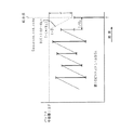
次に、図6は、上記図5の復号側の受信バッファ(デコーダバッファ)106の動作を説明するための図である。この図6は、受信バッファ106に入力された画像ビットストリームの占有率を図示したものである。この受信バッファ106には、一定レートで画像データが入力され、この一定レートの入力が右上がりの直線で示されている。それぞれの画像データP1,P2,P3,…は、基本的には、予め決められた各々の復号時刻t1,t2,t3,…に、符号化単位(アクセスユニット単位:AU単位)でバッファから引き抜かれる。このため、バッファ占有量は、図6に示すように鋸歯状の軌跡を描くことになる。
Next, FIG. 6 is a diagram for explaining the operation of the decoding-side reception buffer (decoder buffer) 106 in FIG. FIG. 6 illustrates the occupation rate of the image bit stream input to the
このようなデコーダバッファをオーバーフローやアンダーフローさせないように符号化する、という内容が、上記規格ISO11172-2又はISO13818-2のAnnex C に規定されるVBV(Video Buffer Verifier) の規定である。この内容は、ビットストリームが上記MPEGの条件を満足していると認定されるための必要条件となる。 The content of encoding such a decoder buffer so as not to overflow or underflow is the definition of VBV (Video Buffer Verifier) defined in Annex C of the standard ISO11172-2 or ISO13818-2. This content is a necessary condition for the bitstream to be recognized as satisfying the MPEG conditions.
ところで、上述したようなMPEG1(ISO11172-2)、MPEG2(ISO13818-2)の規格に基づいて符号化された画像信号を複数扱う場合に、別々の系で独立に符号化されたビットストリームを結合することは、一般的に困難である。特に、結合点において、連続して画像が静止(フリーズ)せずに結合される、いわゆるシームレスな結合というのは、何ら制限を加えないで生成したビットストリームでは殆ど不可能である。 By the way, when handling a plurality of image signals encoded based on the MPEG1 (ISO11172-2) and MPEG2 (ISO13818-2) standards as described above, bitstreams encoded independently in different systems are combined. It is generally difficult to do. In particular, a so-called seamless combination in which images are continuously combined without being frozen at the combination point is almost impossible with a bitstream generated without any limitation.
図7は、単純に2つのビットストリームを結合した例を示している。この図7の例においては、時間的に前の第1のビットストリームBS1の表示終了の直後に、次の第2のビットストリームBS2の復号を開始した場合を示している。一般にビットストリームの先頭では、バッファにある程度のデータを蓄積してから復号を開始するためのスタートアップディレイという待ち時間が必要である。このため、結合点Jでは、このディレイの分、次の復号画像の復号/表示が遅れることになり、表示フレームが数フレーム分静止(フリーズ)するという現象が生じる。従って、このような場合、いわゆるシームレスな再生が行えない。なお、この図7において、図中の時点x1でデータ供給が停止して、結合点Jで第1のビットストリームBS1の最後のピクチャが引き抜かれ、時点x2でフレームをフリーズ(静止)してビットストリームを結合し、次の時点x3で第2のビットストリームBS2の最初のピクチャが引き抜かれている。 FIG. 7 shows an example in which two bit streams are simply combined. In the example of FIG. 7, the decoding of the next second bit stream BS 2 is started immediately after the display of the first bit stream BS 1 preceding in time is finished. Generally, at the beginning of a bit stream, a waiting time called a start-up delay is required to start decoding after accumulating a certain amount of data in a buffer. For this reason, at the connection point J, the decoding / display of the next decoded image is delayed by this delay, and a phenomenon occurs in which the display frame is frozen for several frames. Therefore, in such a case, so-called seamless reproduction cannot be performed. In FIG. 7, the data supply stops at the time point x 1 in the figure, the last picture of the first bit stream BS 1 is extracted at the connection point J, and the frame is frozen (still) at the time point x 2. and combines the bit stream, the first picture at the next time point x 3 second bit stream BS 2 has been withdrawn.
次に、図8は、上記図7と同様なビットストリームをシームレスに再生するために、上記スタートアップディレイの分だけバッファへのデータ入力を前倒しした例を示している。この図8の例では、シームレスな再生を優先したため、時間的に後のビットストリームBS2の先頭の画像の復号が、時間的に前のビットストリームBS1の最後の画像の復号(図8中の結合点J)から、1/FR分(ただし、FRはフレームレート)の時間後(図8中の時点x2) に復号されるようになっている。この場合、ビットストリームBS1の最後の画像(結合点Jで引き抜かれるピクチャ)の復号より前(図8中の時点x1) に、ビットストリームBS2がバッファに入力されるために、ビットストリームBS1の最後の画像の復号時(結合点J)に、デコーダバッファの占有量がオーバーフローを引き起こすことになる。
Next, FIG. 8 shows an example in which data input to the buffer is advanced by the amount corresponding to the start-up delay in order to seamlessly reproduce the same bit stream as in FIG. In the example of FIG. 8, since seamless playback is given priority, decoding of the head image of the bit stream BS 2 that is temporally later is performed by decoding the last image of the bit stream BS 1 that is temporally earlier (in FIG. 8 The data is decoded after a
すなわち、従来の符号化方法で符号化された画像信号のビットストリームをシームレスに結合することは、一般的にほぼ不可能であった。 That is, it has been generally impossible to seamlessly combine the bit streams of image signals encoded by the conventional encoding method.
本発明は、上述したような実情に鑑みてなされたものであり、2つの画像信号のビットストリームを結合する場合に、デコーダバッファの占有量がオーバーフローやアンダーフローすることなく、また静止画を挟むことなくシームレスに結合が行えるようなディジタル信号符号化方法、編集方法、及び伝送方法の提供を目的とするものである。 The present invention has been made in view of the above-described circumstances. When the bit streams of two image signals are combined, the occupation amount of the decoder buffer does not overflow or underflow, and a still image is sandwiched. It is an object of the present invention to provide a digital signal encoding method, an editing method, and a transmission method that can be seamlessly combined.
上記の課題を解決するために、本発明は、ディジタル信号のビットストリームを符号化して出力する場合に、圧縮符号化された複数のビットストリームを結合する場合の時間的に前となる第1のビットストリームの終端付近のデコーダバッファ占有量に対して、第1の所定の制限を設けて符号化することを特徴としている。 In order to solve the above-described problems, the present invention provides a first time that precedes when a plurality of compression-coded bit streams are combined when a bit stream of a digital signal is encoded and output. The decoder buffer occupancy near the end of the bitstream is encoded with a first predetermined limit.
また、本発明は、圧縮符号化された複数のビットストリームを結合する場合の時間的に後となる第2のビットストリームの先頭付近のデコーダバッファ占有量に対して、第2の所定の制限を設けて符号化することを特徴とする。 In addition, the present invention places a second predetermined limit on the decoder buffer occupancy near the beginning of the second bit stream that is later in time when a plurality of compression-encoded bit streams are combined. It is provided and encoded.
ここで、上記第1、第2の制限は、結合される時間的に後の上記第2のビットストリームのスタートアップに必要なデコーダバッファ量を確保するための制限である。より具体的には、上記第1の所定の制限としては、結合される時間的に後の第2のビットストリームのスタートアップに必要なバッファ量をα、符号化ビットレートをRB、上記第1のビットストリームの最後の画像のバッファからの引き抜き時刻をTとするとき、T−(α/RB)の時刻からバッファ占有量の制限が開始され、この時刻をt=0とするときのバッファ占有量をBO(t) とし、バッファの全容量をBFとするとき、BO(t)=BF−RB×tとなるような制限を加えて上記第1のビットストリームの終端付近を符号化する。また、上記第2の所定の制限としては、結合される時間的に後の第2のビットストリームの先頭の画像のバッファからの引き抜き時刻をT’とし、フレームレートをRFとするとき、T’−1/RFの時刻におけるバッファ占有量βが、上記第2のビットストリームのスタートアップに必要なバッファ量αに対して、β<αとなるような制限を加えて上記第2のビットストリームの先頭付近を符号化する。 Here, the first and second restrictions are those for securing a decoder buffer amount necessary for start-up of the second bit stream that is temporally combined. More specifically, as the first predetermined restriction, the buffer amount necessary for start-up of the second bit stream that is combined later in time is α, the encoding bit rate is R B , and the first When the extraction time from the last image buffer of the bit stream of T is T, the buffer occupancy limit is started from the time of T− (α / R B ), and the buffer when this time is set to t = 0 When the occupation amount is BO (t) and the total capacity of the buffer is BF, a restriction such that BO (t) = BF−R B × t is added and the vicinity of the end of the first bit stream is encoded. To do. Further, the second predetermined restriction is that when the time of extraction from the buffer of the head image of the second bit stream that is later in time to be combined is T ′ and the frame rate is R F , T A buffer occupation amount β at the time of “−1 / R F is added to the second bit stream by adding a restriction such that β <α with respect to the buffer amount α required for startup of the second bit stream. Encode the vicinity of the beginning of.
また、本発明は、制限を加えて符号化された上記第1のビットストリームと上記第2のビットストリームとを結合する際に、上記第1のビットストリームの最後に付加されているsequence_end_code (シーケンスエンドコード)を削除し、上記バッファ量α、βに対して、(α−β)及び削除された上記sequence_end_code 分の充填ビットをビットストリームに加えて結合することを特徴とする。 Further, the present invention provides a sequence_end_code (sequence) added to the end of the first bit stream when the first bit stream encoded with restriction and the second bit stream are combined. (End code) is deleted, and (α−β) and the filling bits for the deleted sequence_end_code are added to the bitstream and combined with the buffer amounts α and β.
本発明によれば、複数のビットストリームを結合する場合に、結合点の前の第1のビットストリームの終端付近のデコーダバッファ占有量に対して、第1の所定の制限を設けて符号化し、また、結合点の後の第2のビットストリームの先頭付近のデコーダバッファ占有量に対して、第2の所定の制限を設けて符号化しているため、シームレスな結合をバッファの破綻無く行うことができる。 According to the present invention, when combining a plurality of bit streams, the decoder buffer occupancy near the end of the first bit stream before the combining point is encoded with a first predetermined limit, In addition, since the decoder buffer occupancy near the beginning of the second bitstream after the coupling point is encoded with the second predetermined restriction, seamless coupling can be performed without buffer failure. it can.
ここで、第1、第2の制限は、第2のビットストリームのスタートアップに必要なデコーダバッファ量を確保するための制限であり、このような制限を加えて符号化された第1、第2のビットストリームを結合することにより、MPEG1(ISO11172-2)又はMPEG2(ISO13818-2)を用いて圧縮符号化された2本のビデオのビットストリームを、VBV(Video Buffer Verifier) の規定を守り、かつ画像の表示がフリーズ(静止)などを伴わずに連続してビットストリームの結合が行える。 Here, the first and second restrictions are restrictions for securing a decoder buffer amount necessary for the start-up of the second bit stream, and the first and second encoded data are added with such a restriction. By combining these bitstreams, two video bitstreams that have been compression-encoded using MPEG1 (ISO11172-2) or MPEG2 (ISO13818-2) can be maintained in compliance with VBV (Video Buffer Verifier) regulations. In addition, it is possible to continuously combine the bitstreams without causing the image display to freeze (still).
以下、本発明の実施の形態について図面を参照しながら説明する。 Hereinafter, embodiments of the present invention will be described with reference to the drawings.
図1は、本発明の実施の形態を説明するための図である。この図1に示す実施の形態においては、入力端子11に供給された第1の画像信号を符号化装置10で符号化して得られた第1のビットストリームの後に、入力端子21に供給された第2の画像信号を符号化装置20で符号化して得られた第2のビットストリームを結合する場合を想定している。
FIG. 1 is a diagram for explaining an embodiment of the present invention. In the embodiment shown in FIG. 1, after the first bit stream obtained by encoding the first image signal supplied to the input terminal 11 by the
図1の符号化装置10の入力端子11に供給された第1の画像信号は、上述したいわゆるMPEG1(ISO11172-2)又はMPEG2(ISO13818-2)に対応した符号化部12に送られて圧縮符号化され、第1のビットストリームとして取り出される。この場合に、各画像が圧縮の単位となるが、この圧縮符号化された画像データの大きさは一定ではないので、出力段に送信バッファ13を設けて、このバッファの占有量を符号化にフィードバックさせることによって、送信バッファ13をオーバーフロー/アンダーフローさせないように画像の符号量を調整している。このとき、上記第1の画像信号を符号化して得られる第1のビットストリームの終端付近のデコーダバッファ占有量に対して制限を設けて符号化しており、特に、第1のビットストリームの後に連結される第2のビットストリームのスタートアップに必要とされるデコーダバッファ量を確保するための制限を、第1のビットストリームの終端付近のバッファ占有量に対して設けている。この制限については、端子14からの制御信号に応じて施されるものであるが、その内容については図2を参照しながら後述する。
The first image signal supplied to the input terminal 11 of the
また、符号化装置20の入力端子21に供給された第2の画像信号は、上述と同様にMPEG1(ISO11172-2)又はMPEG2(ISO13818-2)に対応した符号化部22に送られて圧縮符号化され、第2のビットストリームとされるが、出力段に送信バッファ23を設けて、このバッファの占有量を符号化装置にフィードバックさせることによって、送信バッファ23をオーバーフロー/アンダーフローさせないように画像の符号量を調整している。このとき、第2のビットストリームの終端付近のバッファ占有量に対して制限を設けており、特に、上記第2のビットストリームのスタートアップに必要とされるバッファ量を確保するための制限を、第2のビットストリームの終端付近のバッファ占有量に対して設けている。この制限については、端子24からの制御信号に応じて施されるものであるが、その内容については図3を参照しながら後述する。
Further, the second image signal supplied to the
これらの符号化装置10からの第1のビットストリーム及び符号化装置20からの第2のビットストリームは、ビットストリーム結合部30において第1のビットストリームの後に第2のビットストリームの順に結合され、出力端子36より取り出される。この結合については、図4を参照しながら後述する。
The first bit stream from the
すなわち、結合部30で結合する第1、第2のビットストリームの時間的に前の第1のビットストリームの終端近傍でのバッファ占有量にある制限を設けて符号化装置10で符号化しておき、なおかつ時間的に後ろの第2のビットストリームの先頭部分でのバッファ占有量にある制限を設けて符号化装置20で符号化しておくことによって、上記MPEG1(ISO11172-2)又はMPEG2(ISO13818-2)に規定されるVBV(Video Buffer Verifier) の規定を守り、かつシームレスに、すなわち画像の表示がフリーズ等を伴わず連続して行えるように結合するわけである。
In other words, the
これは、結合点においてシームレスな結合を行った場合、上述した従来例に説明したようなデコーダバッファのオーバーフローが起きる可能性があるため、シームレス結合に必要なスタートアップに必要とされるバッファ量を予め見込んで、結合点の前後における符号化制御を行うものである。 This is because, when seamless coupling is performed at the coupling point, there is a possibility that the decoder buffer overflow as described in the above-described conventional example may occur. In view of this, encoding control is performed before and after the coupling point.
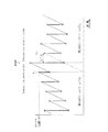
具体的には、結合点Jの前に位置する第1のビットストリームBS1の終わり付近のビットレートを、図2に示すように制限する。ここで、予め決められた、連結される後ろの第2のビットストリームをシームレスに連結した場合のスタートアップに必要なバッファ量をαとする。このバッファ量αは、現実の運用において適当な値を設定する。符号化ビットレートをRBで表し、バッファの全容量をBFとし、最後の画像のバッファからの引き抜き時刻をTとする。 Specifically, the bit rate near the end of the first bit stream BS 1 located before the joining point J is limited as shown in FIG. Here, it is assumed that α is a buffer amount necessary for start-up when the second bit stream to be connected is seamlessly connected in advance. The buffer amount α is set to an appropriate value in actual operation. The encoding bit rate is represented by R B , the total capacity of the buffer is BF, and the extraction time of the last image from the buffer is T.
この場合、結合点Jの時刻をTとすると、バッファ占有量の制限としては、
T−(α/RB)
の時刻から開始され、この時刻をt=0として、時間が進む方向を正とし、バッファの占有量はtの関数として表されるため、これをBO(t) とすると、
BO(t)=BF−RB×t
となるような制限を加えて、結合よりも時間的に前のビットストリームの終端近傍を符号化する。これが結合点の前における第1のビットストリームBS1への制限となる。図1においては、端子14からの制御信号が符号化部12に与えられることにより、ビットストリームの終端付近の符号化の際に、上述したような制限が加えられる。
In this case, if the time of the connection point J is T,
T- (α / R B )
Since this time is t = 0, the direction of time advance is positive, and the buffer occupancy is expressed as a function of t.
BO (t) = BF−R B × t
In this way, the vicinity of the end of the bitstream before the combination is encoded. This is a restriction on the first bitstream BS1 before the coupling point. In FIG. 1, the control signal from the terminal 14 is given to the
同様に、結合点Jの後ろに位置する第2のビットストリームBS2の先頭付近のビットレートを、図3に示すように制限する。最初のフレームの表示時刻の1/RF前のバッファ占有量が上記αより小さいように、スタートアップ時のビットレートを制限しておくわけである。すなわち、後ろの第2のビットストリームBS2の先頭のピクチャのバッファからの引き抜き時刻をT’とし、フレームレートをRFとした場合に、(T’−1/RF)の時刻におけるバッファ占有量βが、予め決められた第2のビットストリームBS2をシームレスに連結した場合のスタートアップに必要なバッファ量αに対して、β<αとなるような制限を加えて、後ろの第2のビットストリームBS2の先頭部分を符号化する。図1においては、端子24からの制御信号が符号化部22に与えられることにより、ビットストリームの先頭付近の符号化の際に、上述したような制限が加えられる。 Similarly, the bit rate in the vicinity of the head of the second bit stream BS2 located after the connection point J is limited as shown in FIG. As the buffer occupancy of the 1 / R F before the display time of the first frame is less than the alpha, is not kept to limit the bit rate at the time of startup. That is, when the extraction time from the buffer of the first picture of the second bit stream BS 2 is T ′ and the frame rate is R F , the buffer occupancy at the time of (T′−1 / R F ) the amount beta is, the second bit stream BS 2 relative seamless buffer amount required for startup when linked to the α determined in advance, beta <added α become such restrictions, behind the second encoding a first portion of the bit stream BS 2. In FIG. 1, the control signal from the terminal 24 is given to the encoding unit 22, so that the above-described restriction is added when encoding near the head of the bit stream.
この図3中のVBV_dilayとは、上記MPEG1(ISO11172-2)又はMPEG2(ISO13818-2)に規定されるVBV(Video Buffer Verifier) の規定により、デコーダ側のバッファにおいて引き抜かれるピクチャに対して必要とされるバッファ蓄積量を時間で示したものであり、デコーダにビットストリームが供給が開始されてVBV_dilayの期間が経過した時刻(T’)に、最初の表示単位のピクチャがバッファから引き抜かれ、復号される。 The VBV_dilay in FIG. 3 is necessary for the picture extracted in the buffer on the decoder side according to the definition of VBV (Video Buffer Verifier) defined in MPEG1 (ISO11172-2) or MPEG2 (ISO13818-2). The amount of buffer storage to be performed is shown in time, and the picture of the first display unit is extracted from the buffer and decoded at the time (T ′) when the VBV_dilay period has elapsed since the start of the supply of the bit stream to the decoder. Is done.
以上の図2、図3と共に説明したような制限が加えられて符号化された第1、第2のビットストリームを、図1のビットストリーム結合部30に送って結合する場合の具体例について、図4を参照しながら説明する。
A specific example of the case where the first and second bitstreams encoded with the restrictions described with reference to FIGS. 2 and 3 are sent to the
図4は、上述した条件に従ってエンコードしたものを結合した具体例を示している。この場合、前の第1のビットストリームBS1の最後の部分では、上記αの分のバッファ占有量と、これを時間換算したα/RBの分のスタートアップディレイをマージンとして持っているために、後ろの第2のビットストリームBS2を結合しても、バッファのオーバーフローを引き起こすことはない。また、実際の結合では、前の第1のビットストリームBS1の最後の部分のsequence_end_code (シーケンスエンドコード)を削除し、削除されたsequence_end_code と(α−β)の分については、ビット充填(bit stuffing)を行うことで、整合性の保たれた結合が可能となる。 FIG. 4 shows a specific example in which those encoded according to the above-described conditions are combined. In this case, the first end portion of the bitstream BS 1 before, in order to have a minute buffer occupancy of the alpha, the minute startup delay-converted alpha / R B this time as a margin Combining the subsequent second bitstream BS2 does not cause a buffer overflow. Further, in the actual combination, the sequence_end_code (sequence end code) of the last part of the previous first bit stream BS 1 is deleted, and the deleted sequence_end_code and (α−β) are filled with bits (bit By performing (stuffing), it is possible to achieve a consistent connection.
すなわち、第1のビットストリームBS1の最後のレートコントロールを、上記αを用いたオーバーフローレベルBO(t) に抑え込むように第1の符号化装置10で符号化し、第2のビットストリームBS2の先頭で、時刻(T’−1/RF)でのバッファ占有量βが上記αより小さくなる(β<α)ように第2の符号化装置20で符号化することにより、シームレスな結合を行ってもバッファがオーバーフローしないことが保証され、αとβとの差分及び上記削除された第1のビットストリームBS1び終端の部分のsequence_end_code については、無効データ(例えば0等)を充填することで、MPEGのVBV(Video Buffer Verifier) の規定の整合性を保ったままでビットストリームの結合を実現している。
In other words, the first bit stream BS 1 is encoded by the
ここで、図1のビットストリーム結合部30においては、符号化装置10からの第1のビットストリームBS1の最後の部分のsequence_end_code をデマルチプレクサ31で検出してCPU35に送っており、符号化装置20からの第2のビットストリームBS2の先頭の部分のsequence_start_code (シーケンススタートコード)をデマルチプレクサ32で検出してCPU35に送っている。これらのデマルチプレクサ31、32からの第1、第2のビットストリームBS1、BS2は、切換スイッチ34の被選択端子a,bにそれぞれ送られており、切換スイッチ34の第3の被選択端子cには、ビット充填回路33からの充填用ビットが供給されている。この切換スイッチ34は、CPU35からの制御信号により切換制御されており、CPU35は、デマルチプレクサ31、32からの第1のビットストリームBS1の最後の部分のsequence_end_code や、第2のビットストリームBS2の先頭の部分のsequence_start_code に基づいて、切換スイッチ34を被選択端子aからcを介してbに順次切換接続することにより、第1のビットストリームBS1の最後の部分のsequence_end_code を削除すると共に、このsequence_end_code と上記α−βの分を、ビット充填回路33からの充填ビット(スタッフィングビット)STで補充して、第2のビットストリームBS2に連結している。切換スイッチ34からの出力ビットストリームは、出力端子36を介して取り出される。
Here, in the bit
ところで、以上は符号化装置10から出力された第1のビットストリームの後に符号化装置20から出力された第2のビットストリームを連結した場合の例であるが、符号化装置20から出力されたビットストリームの後に符号化装置10から出力されたビットストリームを結合する場合には、符号化装置20から出力されるビットストリームの終端付近で上記バッファ量αに基づくオーバーフローレベルBO(t) に抑え込むように符号化装置20での符号化を制限し、符号化装置10から出力されるビットストリームの先頭で、時刻(T’−1/RF)での上記バッファ占有量βが上記αより小さくなる(β<α)ように符号化装置10での符号化を制限すればよい。この場合には、ビットストリーム結合部30は、デマルチプレクサ32が符号化装置20から出力されたビットストリームの終端の部分のsequence_end_code を検出してCPU35に送り、デマルチプレクサ31が符号化装置10から出力されたビットストリームの先頭の部分のsequence_start_code を検出してCPU35に送ることになる。これらの情報に基づいて、CPU35は、切換スイッチ34の被選択端子bからcを経てaの順に切換制御し、符号化装置20から出力されたビットストリームの終端の部分のsequence_end_code を削除して、ビット充填回路33からの充填ビットをこのsequence_end_code と(α−β)の分だけ充填した後に、符号化装置10から出力されたビットストリームを連結して、出力端子36に送る。
By the way, the above is an example when the second bit stream output from the
また、符号化装置10から出力される1つのビットストリームについて、当該ビットストリームの先頭部分に上記図3の制限を加えた符号化を施し、該ビットストリームの終端部分に上記図2の制限を加えた符号化を施すことにより、当該ビットストリームの前後にそれぞれ他のビットストリームを結合することができるようになる。
In addition, for one bit stream output from the
上述したような図1の構成が適用されるシステムの具体例としては、例えば放送衛星等を介してメインの放送局とローカルの放送局とが結ばれて成るような放送ネットワークを挙げることができる。この放送ネットワークにおいて、メインの放送局からの番組を符号化装置10で符号化して各ローカル局に提供し、各ローカル局では、それぞれの地域毎のローカルニュースやCM等を符号化装置20で符号化したものを結合して出力端子36より取り出し、それぞれの地域内に送出する。このとき、メインの局からの放送番組のビットストリームの終端部分については、バッファ占有量が上記図2と共に説明したBO(t)=BF−RBt を越えない制限が加えられた符号化が施されており、この後に結合されるローカル局からの信号のビットストリームの先頭部分については、上記図3と共に説明したように、上記時刻(T’−1/RF)でのバッファ占有量βが上記バッファ量αを越えない(β<α)ような制限が加えられた符号化が施されており、これらが結合部30でビット充填を含めてシームレスに結合されて得られたビットストリームについては、デコード時にバッファの破綻がない、すなわちバッファのオーバーフローやアンダーフローが生じない。
As a specific example of the system to which the configuration of FIG. 1 as described above is applied, for example, a broadcasting network in which a main broadcasting station and a local broadcasting station are connected via a broadcasting satellite or the like can be cited. . In this broadcasting network, a program from a main broadcasting station is encoded by the
以上説明したような実施の形態によれば、画像信号を上記MPEG1(ISO11172-2)又はMPEG2(ISO13818-2)を用いて圧縮符号化された2本のビデオのビットストリームを結合する場合に、上記VBV(Video Buffer Verifier) の規定を守り、かつ画像の表示がフリーズ(静止)などを伴わずに連続して行えるようなシームレスに結合することがができる。 According to the embodiment as described above, when two video bit streams compression-encoded using an MPEG1 (ISO11172-2) or MPEG2 (ISO13818-2) image signal are combined, The above-mentioned VBV (Video Buffer Verifier) regulations can be observed, and the images can be seamlessly combined so that they can be displayed continuously without being frozen.
上述したような本発明の実施の形態によれば、複数のビットストリームを結合する場合に、結合点の前の第1のビットストリームの終端付近のデコーダバッファ占有量に対して、第1の所定の制限を設けて符号化し、また、結合点の後の第2のビットストリームの先頭付近のデコーダバッファ占有量に対して、第2の所定の制限を設けて符号化しているため、シームレスな結合をバッファの破綻無く行うことができる。 According to the embodiment of the present invention as described above, when a plurality of bit streams are combined, the first predetermined amount with respect to the decoder buffer occupancy near the end of the first bit stream before the combining point is determined. Is encoded, and the decoder buffer occupancy near the beginning of the second bitstream after the combination point is encoded with the second predetermined limit, so that seamless combination is possible. Can be performed without buffer failure.
ここで、第1、第2の制限は、第2のビットストリームのスタートアップに必要なデコーダバッファ量を確保するための制限であり、このような制限を加えて符号化された第1、第2のビットストリームを結合することにより、MPEG1(ISO11172-2)又はMPEG2(ISO13818-2)を用いて圧縮符号化された2本のビデオのビットストリームを、VBV(Video Buffer Verifier) の規定を守り、かつ画像の表示がフリーズ(静止)などを伴わずに連続してビットストリームの結合が行える。 Here, the first and second restrictions are restrictions for securing a decoder buffer amount necessary for the start-up of the second bit stream, and the first and second encoded data are added with such a restriction. By combining these bitstreams, two video bitstreams that have been compression-encoded using MPEG1 (ISO11172-2) or MPEG2 (ISO13818-2) can be maintained in compliance with VBV (Video Buffer Verifier) regulations. In addition, it is possible to continuously combine the bitstreams without causing the image display to freeze (still).
なお、本発明は上述した実施の形態のみに限定されるものではなく、本発明の要旨を逸脱しない範囲において種々の変更が可能であることは勿論である。 It should be noted that the present invention is not limited to the above-described embodiments, and various modifications can be made without departing from the scope of the present invention.
10,20 符号化装置、 12,22 符号化部、 13,23 送信バッファ、 30 ビットストリーム結合部、 31,32 デマルチプレクサ、 33 ビット充填回路、 34 切換スイッチ、 35 CPU
10,20 encoding device, 12,22 encoding unit, 13,23 transmission buffer, 30 bit stream combining unit, 31,32 demultiplexer, 33 bit filling circuit, 34 changeover switch, 35 CPU
Claims (12)
圧縮符号化された複数のビットストリームを結合する場合の時間的に前となる第1のビットストリームの終端付近でのバッファ占有量に対して、所定の制限を設けて符号化する
ことを特徴とするディジタル信号符号化方法。 In a digital signal encoding method for encoding a bit stream of a digital signal,
Encoding with a predetermined restriction on the buffer occupancy in the vicinity of the end of the first bitstream that is temporally preceding when combining a plurality of compression-encoded bitstreams A digital signal encoding method.
ことを特徴とする請求項1記載のディジタル信号符号化方法。 2. The digital signal encoding method according to claim 1, wherein the predetermined limit is a limit for securing a buffer amount necessary for start-up of the second bit stream that is combined later in time.
ことを特徴とする請求項1記載のディジタル信号符号化方法。 The predetermined restrictions include: α for the amount of buffer required for start-up of the second bitstream that is combined later in time, R B for the encoding bit rate, and buffer for the last image of the first bitstream. When the extraction time from T is T, the buffer occupancy limit is started from the time T- (α / R B ), and the buffer occupancy when this time is set to t = 0 is BO (t), The encoding near the end of the first bitstream is performed by adding a restriction such that BO (t) = BF−R B × t when the total capacity of the buffer is BF. A digital signal encoding method as described.
圧縮符号化された複数のビットストリームを結合する場合の時間的に後となる第2のビットストリームの先頭付近でのバッファ占有量に対して、所定の制限を設けて符号化する
ことを特徴とするディジタル信号符号化方法。 In a digital signal encoding method for encoding a bit stream of a digital signal,
Encoding with a predetermined restriction on the buffer occupancy in the vicinity of the beginning of the second bit stream that is later in time when a plurality of compression-encoded bit streams are combined. A digital signal encoding method.
ことを特徴とする請求項4記載のディジタル信号符号化方法。 5. The digital signal encoding method according to claim 4, wherein the predetermined limit is a limit for securing a buffer amount necessary for start-up of the second bit stream that is combined later in time. .
ことを特徴とする請求項4記載のディジタル信号符号化方法。 As the predetermined restriction, when the extraction time from the buffer of the first image of the second bit stream that is later in time is T ′ and the frame rate is R F , T′−1 / R The buffer occupancy β at the time F is restricted so that β <α with respect to the buffer amount α required for startup of the second bit stream, and the vicinity of the head of the second bit stream is encoded. The digital signal encoding method according to claim 4, wherein:
結合される時間的に前の第1のビットストリームの終端付近でのバッファ占有量に対して、所定の制限を設けて符号化し、
結合される時間的に後の第2のビットストリームの先頭付近でのバッファ占有量に対して、所定の制限を設けて符号化する
ことを特徴とするディジタル信号編集方法。 In a digital signal editing method for combining and outputting a plurality of bit streams obtained by compressing and encoding a plurality of digital signals,
Encoding with a predetermined limit on the buffer occupancy near the end of the first bitstream that is temporally previous to be combined,
A digital signal editing method comprising: encoding with a predetermined restriction on a buffer occupancy in the vicinity of the beginning of a second bit stream that is temporally combined later.
上記第2のビットストリームの先頭付近でのバッファ占有量に対する所定の制限は、結合される時間的に後の上記第2のビットストリームのスタートアップに必要なバッファ量を確保するための制限である
ことを特徴とする請求項7記載のディジタル信号編集方法。 The predetermined limit on the buffer occupation amount near the end of the first bit stream is a limit for securing a buffer amount necessary for the start-up of the second bit stream that is combined later in time,
The predetermined limit on the buffer occupancy in the vicinity of the head of the second bit stream is a limit for securing a buffer amount necessary for the start-up of the second bit stream that is combined later in time. The digital signal editing method according to claim 7.
上記第2のビットストリームの先頭付近でのバッファ占有量に対する所定の制限としては、結合される時間的に後の第2のビットストリームの先頭の画像のバッファからの引き抜き時刻をT’とし、フレームレートをRFとするとき、T’−1/RFの時刻におけるバッファ占有量βが、上記第2のビットストリームのスタートアップに必要なバッファ量αに対して、β<αとなるような制限を加えて上記第2のビットストリームの先頭付近を符号化する
ことを特徴とする請求項7記載のディジタル信号編集方法。 As a predetermined restriction on the buffer occupancy near the end of the first bit stream, α is the buffer amount necessary for the start-up of the second bit stream that is combined later, and the encoding bit rate is R B , when the extraction time of the last image of the first bitstream from the buffer is T, the buffer occupancy limit is started from the time of T− (α / R B ), and this time is set to t = When the buffer occupation amount is set to 0 and BO (t) is set, and the total capacity of the buffer is set to BF, the first bit stream is added with a restriction such that BO (t) = BF−R B × t. Encode near the end of
As a predetermined restriction on the buffer occupancy in the vicinity of the head of the second bit stream, the extraction time from the buffer of the head image of the second bit stream that is later combined is T ′, and the frame When the rate is R F , the buffer occupation amount β at the time T′−1 / R F is such that β <α with respect to the buffer amount α required for the startup of the second bitstream. The digital signal editing method according to claim 7, wherein the vicinity of the head of the second bit stream is encoded.
上記第1のビットストリームの最後に付加されているsequence_end_code を削除し、
上記バッファ量α、βに対して、(α−β)及び削除された上記sequence_end_code 分の充填ビットをビットストリームに加えて結合する
ことを特徴とする請求項7記載のディジタル信号編集方法。 When combining the first bitstream and the second bitstream encoded with the above restrictions,
Delete sequence_end_code appended to the end of the first bitstream,
8. The digital signal editing method according to claim 7, wherein (α−β) and the deleted filling bits for sequence_end_code are added to the bit stream and combined with the buffer amounts α and β.
圧縮符号化された複数のビットストリームを結合するための1つのビットストリームの終端付近で、バッファ占有量に対して第1の所定の制限を設けて符号化するとともに、該ビットストリームの先頭付近で、バッファ占有量に対して第2の所定の制限を設けて符号化する
ことを特徴とするディジタル信号符号化方法。 In a digital signal transmission method for encoding, outputting, and transmitting a bit stream of a digital signal,
In the vicinity of the end of one bitstream for combining a plurality of compression-coded bitstreams, encoding is performed with a first predetermined limit on the buffer occupancy, and near the beginning of the bitstream. And encoding with a second predetermined limit for the buffer occupancy.
上記第2の所定の制限としては、現ビットストリームの先頭の画像のバッファからの引き抜き時刻をT’とし、フレームレートをRFとするとき、T’−1/RFの時刻におけるバッファ占有量βが、当該ビットストリームのスタートアップに必要なバッファ量αに対して、β<αとなるような制限を加えて当該ビットストリームの先頭付近を符号化する
ことを特徴とする請求項11記載のディジタル信号伝送方法。
The first predetermined limit is that the buffer amount required for start-up of other bitstreams that are combined later in time is α, the encoding bit rate is R B , and the buffer for the last image of the current bitstream. When the extraction time of T is T, the buffer occupancy limit is started from the time T- (α / R B ). The buffer occupancy when this time is set to t = 0 is BO (t), and the buffer When the total capacity of BF is BF, the vicinity of the end of the current bitstream is encoded by adding a restriction such that BO (t) = BF−R B × t,
As the second predetermined restriction, when the extraction time from the buffer of the head image of the current bitstream is T ′ and the frame rate is R F , the buffer occupation amount at the time T′−1 / R F 12. The digital encoding according to claim 11, wherein β is encoded in the vicinity of the beginning of the bitstream with a restriction such that β <α with respect to a buffer amount α required for startup of the bitstream. Signal transmission method.
Priority Applications (1)
| Application Number | Priority Date | Filing Date | Title |
|---|---|---|---|
| JP2005069728A JP4371066B2 (en) | 2005-03-11 | 2005-03-11 | Editing apparatus and editing method |
Applications Claiming Priority (1)
| Application Number | Priority Date | Filing Date | Title |
|---|---|---|---|
| JP2005069728A JP4371066B2 (en) | 2005-03-11 | 2005-03-11 | Editing apparatus and editing method |
Related Parent Applications (1)
| Application Number | Title | Priority Date | Filing Date |
|---|---|---|---|
| JP15253496A Division JP3668556B2 (en) | 1996-06-13 | 1996-06-13 | Digital signal encoding method |
Publications (2)
| Publication Number | Publication Date |
|---|---|
| JP2005204334A true JP2005204334A (en) | 2005-07-28 |
| JP4371066B2 JP4371066B2 (en) | 2009-11-25 |
Family
ID=34824841
Family Applications (1)
| Application Number | Title | Priority Date | Filing Date |
|---|---|---|---|
| JP2005069728A Expired - Fee Related JP4371066B2 (en) | 2005-03-11 | 2005-03-11 | Editing apparatus and editing method |
Country Status (1)
| Country | Link |
|---|---|
| JP (1) | JP4371066B2 (en) |
-
2005
- 2005-03-11 JP JP2005069728A patent/JP4371066B2/en not_active Expired - Fee Related
Also Published As
| Publication number | Publication date |
|---|---|
| JP4371066B2 (en) | 2009-11-25 |
Similar Documents
| Publication | Publication Date | Title |
|---|---|---|
| US7072571B2 (en) | Data reproduction transmission apparatus and data reproduction transmission method | |
| JP4232209B2 (en) | Compressed image data editing apparatus and compressed image data editing method | |
| JP4088799B2 (en) | Editing apparatus and editing method | |
| KR100784598B1 (en) | Receiving storage device, transmission device, broadcasting system, receiving storage method, transmission method, broadcasting method, program, and medium | |
| US20020016970A1 (en) | Data conversion apparatus and method, data distribution apparatus and method, and data distribution system | |
| US8233780B2 (en) | Reproducing apparatus and method, and recording medium | |
| JPH11511605A (en) | Switching method between signals with reduced bit rate | |
| US20060239563A1 (en) | Method and device for compressed domain video editing | |
| JP2007300593A (en) | Information processing apparatus and information processing method, recording medium, and program | |
| JP3668556B2 (en) | Digital signal encoding method | |
| US7333711B2 (en) | Data distribution apparatus and method, and data distribution system | |
| KR101142379B1 (en) | Method and Apparatus of playing digital broadcasting and Method of recording digital broadcasting | |
| US6940901B2 (en) | Apparatus and method for information processing | |
| WO2003092293A1 (en) | Encoding device and method, decoding device and method, edition device and method, recording medium, and program | |
| US7269839B2 (en) | Data distribution apparatus and method, and data distribution system | |
| JP3649266B2 (en) | Data multiplexing apparatus and method, and recording medium | |
| JP4371066B2 (en) | Editing apparatus and editing method | |
| JPH11177921A (en) | Digital data edit method and digital data edit device | |
| JP2001169285A (en) | Mpeg video decoder | |
| JPH08163558A (en) | Picture decoder | |
| JP2000287172A (en) | Picture data processor | |
| JP2002077827A (en) | Data distributor and distributing method, data distribution system | |
| JP2006187037A (en) | Image reproducing method | |
| JPH10209993A (en) | Encoded signal transmission method and device | |
| JP2002112221A (en) | Data transmission method and device, data transmission system, transmission medium |
Legal Events
| Date | Code | Title | Description |
|---|---|---|---|
| A131 | Notification of reasons for refusal |
Free format text: JAPANESE INTERMEDIATE CODE: A132 Effective date: 20080408 |
|
| A521 | Written amendment |
Free format text: JAPANESE INTERMEDIATE CODE: A523 Effective date: 20080609 |
|
| A131 | Notification of reasons for refusal |
Free format text: JAPANESE INTERMEDIATE CODE: A131 Effective date: 20090602 |
|
| A521 | Written amendment |
Free format text: JAPANESE INTERMEDIATE CODE: A523 Effective date: 20090717 |
|
| TRDD | Decision of grant or rejection written | ||
| A01 | Written decision to grant a patent or to grant a registration (utility model) |
Free format text: JAPANESE INTERMEDIATE CODE: A01 Effective date: 20090811 |
|
| A01 | Written decision to grant a patent or to grant a registration (utility model) |
Free format text: JAPANESE INTERMEDIATE CODE: A01 |
|
| A61 | First payment of annual fees (during grant procedure) |
Free format text: JAPANESE INTERMEDIATE CODE: A61 Effective date: 20090824 |
|
| FPAY | Renewal fee payment (prs date is renewal date of database) |
Free format text: PAYMENT UNTIL: 20120911 Year of fee payment: 3 |
|
| FPAY | Renewal fee payment (prs date is renewal date of database) |
Free format text: PAYMENT UNTIL: 20120911 Year of fee payment: 3 |
|
| FPAY | Renewal fee payment (prs date is renewal date of database) |
Free format text: PAYMENT UNTIL: 20120911 Year of fee payment: 3 |
|
| FPAY | Renewal fee payment (prs date is renewal date of database) |
Free format text: PAYMENT UNTIL: 20130911 Year of fee payment: 4 |
|
| R250 | Receipt of annual fees |
Free format text: JAPANESE INTERMEDIATE CODE: R250 |
|
| R250 | Receipt of annual fees |
Free format text: JAPANESE INTERMEDIATE CODE: R250 |
|
| LAPS | Cancellation because of no payment of annual fees |